

Page 1

Operator’s Manual
Lawn Tractor
Model: WLT-538
IMPORTANT: READ
SAFETY RULES AND
INSTRUCTIONS CAREFULLY.
60 Ottawa Street South, KITCHENER, ONTARIO CANADA N2G 3S7
PRINTED IN U.S.A.
772C0762
(1/12/2005)
Page 2
TABLE OF CONTENTS
Content Page
Customer Support 2
Important Safe Operation Practices 3
Slope Gauge 7
Tractor Set-Up 8
Know Your Lawn Tractor 10
Operating Your Lawn Tractor 13
Making Adjustments 16
Content Page
Maintaining Your Lawn Tractor 18
Service 19
Off Season Storage 23
Attachments & Accessories 23
Troubleshooting 24
Warranty 25
FINDING MODEL NUMBER
This Operator’s Manual is an important part of your new garden tractor. It will help you assemble, prepare and
maintain the unit for best performance . Please read and understand wh at it says.
Before you start assembling your new equipment, please locate the model plat e on the
equipment and copy the information from it in the space provided below. This information will be
necessary to use the manufacturer’s web si te and/or help from t he Customer Suppor t Department or
an authorized service dealer.
• You can locate the model number by looking beneath the seat. A sample mod el plate is explained below.
Model Number
Numéro de modèle
XXXXXXXXXX
Serial Number
Numéro de série
XXXXXXXXXXX
Copy the model number here:
WHITE OUTDOOR CANADA
KITCHENER, ON N2G 4J1
Copy the serial number here:
ENGINE INFORMATION
The engine manufacturer is responsible for all engine-related issues with regards to performance, power-rating, specifications,
warranty and service. Please refer to the engine manufacturer’s Owner’s/Operator’s Manual packed separately with your unit for
more information.
CALLING CUSTOMER SUPPORT
Please do NOT return the unit to the retailer from which it was purchased, without first contacting Customer Support.
If you have difficulty assembling this prod uct or have any questions regar ding the controls, operation or
maintenance of this unit, please call your service dealer.
Please have your unit’s model number and serial number ready when you call. See previou s section to
locate this information.
2
Page 3

SECTION 1: IMPORTANT SAFE OPERATION PRACTICES
WARNING: This symbol points out important safety instructions which, if not followed, could endanger
the personal safety and/or property of yourself and others. Read and follow all instructions in this manual
before attempting to operate this machine. Failure to comply with these instructions may result in personal
injury. When you see this symbol—heed its warning.
DANGER: This machine was built to be operated according to the rules for safe operation in this man-
ual. As with any type of power equipment, carelessness or error on the part of the operator can result in
serious injury. This machine is capable of amputating hands and feet and throwing objects. Failure to
observe the following safety instructions could result in serious injury or death.
GENERAL OPERATION
1. Read, understand, and follow all instructions on the
machine and in the manual(s) before attempting to
assemble and operate. Keep this manual in a safe
place for future and regular reference and for
ordering replacement parts.
2. Be familiar with all controls and their proper
operation. Know how to stop the machine and
disengage them quickly.
3. Never allow children under 14 years old to operate
this machine. Children 14 years old and over
should read and understand the operation
instructions and safety rules in this manual and
should be trained and supervised by a parent.
4. Never allow adults to operate this machine without
proper instruction.
5. To help avoid blade contact or a thrown object
injury, keep bystanders, helpers, children and pets
at least 75 feet from the machine while it is in
operation. Stop machine if anyone enters the area.
6. Thoroughly inspect the area where the equipment
is to be used. Remove all stones, sticks, wire,
bones, toys, and other foreign objects which could
be picked up and thrown by the blade(s). Thrown
objects can cause serious personal injury.
7. Plan your mowing pattern to avoid discharge of
material toward roads, sidewalks, bystanders and
the like. Also, avoid discharging material against a
wall or obstruction which may cause discharged
material to ricochet back toward the operator.
8. Always wear safety glasses or safety goggles
during operation and while performing an
adjustment or repair to protect your eyes. Thrown
objects which ricochet can cause serious injury to
the eyes.
9. Wear sturdy, rough-soled work shoes and closefitting slacks and shirts. Loose fitting clothes and
jewelry can be caught in movable parts. Never
operate this machine in bare feet or sandals.
10. Be aware of the mower and attachment discharge
direction and do not point it at anyone. Do not
operate the mower without the discharge cover or
entire grass catcher in its proper place.
11. Do not put hands or feet near rotating parts or
under the cutting deck. Contact with the blade(s)
can amputate hands and feet.
12. A missing or damaged discharge cover can cause
blade contact or thrown object injuries.
13. Stop the blade(s) when crossing gravel drives,
walks, or roads and while not cutting grass.
14. Watch for traffic when operating near or crossing
roadways. This machine is not intended for use on
any public roadway.
15. Do not operate the machine while under the
influence of alcohol or drugs.
16. Mow only in daylight or good artificial light.
17. Never carry passengers.
18. Disengage blade(s) before shifting into reverse.
Back up slowly. Always look down and behind
before and while backing to avoid a back-over
accident.
19. Slow down before turning. Operate the machine
smoothly. Avoid erratic operation and excessive
speed.
20. Disengage blade(s), set parking brake, stop engine
and wait until the blade(s) come to a complete stop
before removing grass catcher, emptying grass,
unclogging chute, removing any grass or debris, or
making any adjustments.
21. Never leave a running machine unattended. Always
turn off blade(s), place transmission in neutral, set
parking brake, stop engine and remove key before
dismounting.
22. Use extra care when loading or unloading the
machine into a trailer or truck. This unit should not
be driven up or down ramp(s), because the unit
could tip over, causing serious personal injury. The
unit must be pushed manually on ramp(s) to load or
unload properly.
3
Page 4

23. Muffler and engine become hot and can cause a
burn. Do not touch.
24. Check overhead clearances carefully before driving
under low hanging tree branches, wires, door
openings etc., where the operator may be struck or
pulled from the unit, which could result in serious
injury.
25. Disengage all attachment clutches, depress the
brake pedal completely and shift into neutral before
attempting to start engine.
26. Your machine is designed to cut normal residential
grass of a height no more than 10”. Do not attempt
to mow through unusually tall, dry grass (e.g.,
pasture) or piles of dry leaves. Dry grass or leaves
may contact the engine exhaust and/or build up on
the mower deck presenting a potential fire hazard.
27. Use only accessories and attachments approved
for this machine by the machine manufacturer.
Read, understand and follow all instructions
provided with the approved accessory or
attachment.
28. Data indicates that operators, age 60 years and
above, are involved in a large percentage of riding
mower-related injuries. These operators should
evaluate their ability to operate the riding mower
safely enough to protect themselves and others
from serious injury.
29. If situations occur which are not covered in this
manual, use care and good judgment. Contact an
authorized MTD Service Dealer for assistance.
SLOPE OPERATION
Slopes are a major factor related to loss of control and
tip-over accidents which can result in severe injury or
death. All slopes require extra caution. If you cannot
back up the slope or if you feel uneasy on it, do not mow
it.
For your safety, use the slope gauge included as part of
this manual to measure slopes before operating this
unit on a sloped or hilly area. If the slope is greater than
15 degrees as shown on the slope gauge, do not
operate this unit on that area or serious injury could
result.
DO:
1. Mow up and down slopes, not across. Exercise
extreme caution when changing direction on
slopes.
2. Watch for holes, ruts, bumps, rocks, or other
hidden objects. Uneven terrain could overturn the
machine. Tall grass can hide obstacles.
3. Use slow speed. Choose a low enough speed
setting so that you will not have to stop or shift while
on the slope. Tires may lose traction on slopes
even though the brakes are functioning properly.
Always keep machine in gear when going down
slopes to take advantage of engine braking action.
4. Follow the manufacturer’s recommendations for
wheel weights or counterweights to improve
stability.
5. Use extra care with grass catchers or other
attachments. These can change the stability of the
machine.
6. Keep all movement on the slopes slow and gradual.
Do not make sudden changes in speed or direction.
Rapid engagement or braking could cause the front
of the machine to lift and rapidly flip over backwards
which could cause serious injury.
7. Avoid starting or stopping on a slope. If tires lose
traction, disengage the blade(s) and proceed
slowly straight down the slope.
DO NOT:
1. Do not turn on slopes unless necessary; then, turn
slowly and gradually downhill, if possible.
2. Do not mow near drop-offs, ditches or
embankments. The mower could suddenly turn
over if a wheel is over the edge of a cliff, ditch, or if
an edge caves in.
3. Do not try to stabilize the machine by putting your
foot on the ground.
4. Do not use a grass catcher on steep slopes.
5. Do not mow on wet grass. Reduced traction could
cause sliding.
6. Do not shift to neutral and coast downhill. Overspeeding may cause the operator to lose control of
the machine resulting in serious injury or death.
7. Do not tow heavy pull behind attachments (e.g.
loaded dump cart, lawn roller, etc.) on slopes
greater than 5 degrees. When going down hill, the
extra weight tends to push the tractor and may
cause you to loose control. (e.g. tractor may speed
up, braking and steering ability are reduced,
attachment may jack-knife and cause tractor to
overturn).
CHILDREN
1. Tragic accidents can occur if the operator is not
alert to the presence of children. Children are often
attracted to the machine and the mowing activity.
They do not understand the dangers. Never
assume that children will remain where you last
saw them.
a. Keep children out of the mowing area and in
watchful care of a responsible adult other
than the operator.
b. Be alert and turn machine off if a child enters
the area.
c. Before and while backing, look behind and
down for small children.
d. Never carry children, even with the blade(s)
shut off. They may fall off and be seriously
injured or interfere with safe machine
operation.
4
Page 5

e. Use extreme care when approaching blind
corners, doorways, shrubs, trees or other
objects that may block your vision of a child
who may run into the machine.
f. To avoid back-over accidents, always
disengage the cutting blade(s) before
shifting into reverse. The “Reverse
Caution Mode” should not be used when
children or others are around.
g. Keep children away from hot or running
engines. They can suffer burns from a hot
muffler.
h. Remove key when machine is unattended to
prevent unauthorized operation.
i. Never allow children under 14 years old to
operate the machine. Children 14 years old
and over should read and understand the
operation instructions and safety rules in this
manual and should be trained and
supervised by a parent.
TOWING
1. Tow only with a machine that has a hitch designed
for towing. Do not attach towed equipment except
at the hitch point.
2. Follow the manufacturers recommendation for
weight limits for towed equipment and towing on
slopes.
3. Never allow children or others in or on towed
equipment.
4. On slopes, the weight of the towed equipment may
cause loss of traction and loss of control.
5. Travel slowly and allow extra distance to stop.
6. Do not shift to neutral and coast downhill.
SERVICE
SAFE HANDLING OF GASOLINE:
1. To avoid personal injury or property damage
use extreme care in handling gasoline. Gasoline is
extremely flammable and the vapors are explosive.
Serious personal injury can occur when gasoline is
spilled on yourself or your clothes which can ignite.
Wash your skin and change clothes immediately.
a. Use only an approved gasoline container.
b. Never fill containers inside a vehicle or on a
truck or trailer bed with a plastic liner. Always
place containers on the ground away from
your vehicle before filling.
c. When practical, remove gas-powered
equipment from the truck or trailer and refuel
it on the ground. If this is not possible, then
refuel such equipment on a trailer with a
portable container, rather than from a
gasoline dispenser nozzle.
d. Keep the nozzle in contact with the rim of the
fuel tank or container opening at all times
until fueling is complete. Do not use a nozzle
lock-open device.
e. Extinguish all cigarettes, cigars, pipes and
other sources of ignition.
f. Never fuel machine indoors.
g. Never remove gas cap or add fuel while the
engine is hot or running. Allow engine to cool
at least two minutes before refueling.
h. Never over fill fuel tank. Fill tank to no more
than ½ inch below bottom of filler neck to
allow space for fuel expansion.
i. Replace gasoline cap and tighten securely.
j. If gasoline is spilled, wipe it off the engine
and equipment. Move unit to another area.
Wait 5 minutes before starting the engine.
k. To reduce fire hazards, keep machine free of
grass, leaves, or other debris build-up. Clean
up oil or fuel spillage and remove any fuel
soaked debris.
l. Never store the machine or fuel container
inside where there is an open flame, spark or
pilot light as on a water heater, space heater,
furnace, clothes dryer or other gas
appliances.
m. Allow a machine to cool at least 5 minutes
before storing.
GENERAL SERVICE:
1. Never run an engine indoors or in a poorly
ventilated area. Engine exhaust contains carbon
monoxide, an odorless, and deadly gas.
2. Before cleaning, repairing, or inspecting, make
certain the blade(s) and all moving parts have
stopped. Disconnect the spark plug wire and
ground against the engine to prevent unintended
starting.
3. Periodically check to make sure the blades come to
complete stop within approximately (5) five
seconds after operating the blade disengagement
control. If the blades do not stop within the this time
frame, your unit should be serviced professionally
by an authorized MTD Service Dealer.
4. Check brake operation frequently as it is subjected
to wear during normal operation. Adjust and service
as required.
5. Check the blade(s) and engine mounting bolts at
frequent intervals for proper tightness. Also,
visually inspect blade(s) for damage (e.g.,
excessive wear, bent, cracked).
Replace the blade(s) with the original equipment
manufacturer’s (O.E.M.) blade(s) only, listed in this
manual. “Use of parts which do not meet the
original equipment specifications may lead to
improper performance and compromise safety!”
6. Mower blades are sharp. Wrap the blade or wear
gloves, and use extra caution when servicing them.
7. Keep all nuts, bolts, and screws tight to be sure the
equipment is in safe working condition.
5
Page 6
8. Never tamper with the safety interlock system or
other safety devices. Check their proper operation
regularly.
9. After striking a foreign object, stop the engine,
disconnect the spark plug wire(s) and ground
against the engine. Thoroughly inspect the
machine for any damage. Repair the damage
before starting and operating.
10. Never attempt to make adjustments or repairs to
the machine while the engine is running.
11. Grass catcher components and the discharge
cover are subject to wear and damage which could
expose moving parts or allow objects to be thrown.
WARNING: YOUR RESPONSIBILITY Restrict the use of this power machine to persons who read,
understand and follow the warnings and instructions in this manual and on the machine.
.
For safety protection, frequently check components
and replace immediately with original equipment
manufacturer’s (O.E.M.) parts only, listed in this
manual. “Use of parts which do not meet the
original equipment specifications may lead to
improper performance and compromise safety!”
12. Do not change the engine governor settings or
over-speed the engine. The governor controls the
maximum safe operating speed of the engine.
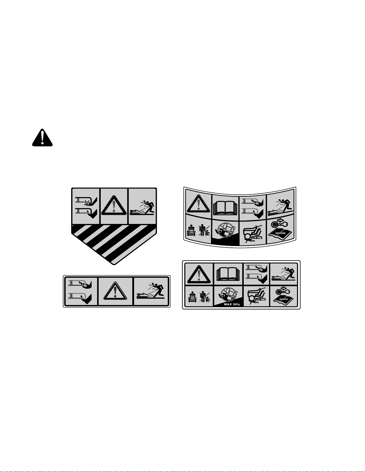
13. Maintain or replace safety and instruction labels, as
necessary.
14. Observe proper disposal laws and regulations for
gas, oil, etc. to protect the environment.
Safety labels found on your unit.
S30011
MAX 20
%
S30544
6
Page 7
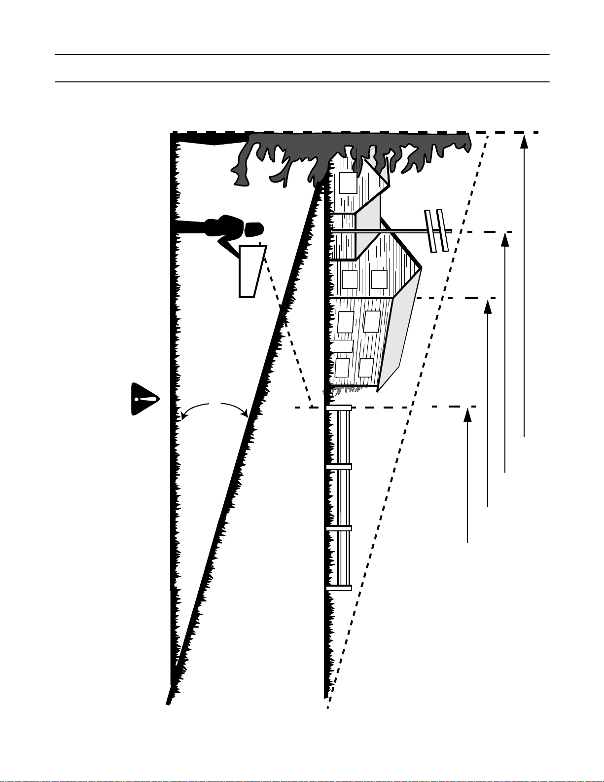
SECTION 2: SLOPE GAUGE
Use this page as a guide to determine slopes where you may not operate safely. Do not operate your equipment
on such slopes.
Operate RIDING mowers up and down slopes, never across the face of slopes.
Operate WALK-BEHIND mowers across the face of slopes, never up and down slopes.
Do not mow on inclines with a slope in excess of 15 degrees (a rise of approximately 2-1/2 feet every 10 feet). A riding mower could
overturn and cause serious injury. If operating a walk-behind mower on such a slope, it is extremely difficult to maintain your footing
and you could slip, resulting in serious injury.
DANGER
15°
F
O
L
D
O
N
D
O
T
T
E
D
L
I
N
E
,
R
E
P
R
E
S
E
N
T
I
N
G
A
1
5
°
S
L
O
P
E
A CORNER OF A BUILDING
OR A FENCE POST
SIGHT AND HOLD THIS LEVEL WITH A VERTICAL TREE
A POWER POLE
7
Page 8
SECTION 3: TRACTOR SET-UP
IMPORTANT:
assembly, service engine with gasoline and oil as instructed in the separate engine manual packed with your unit.
This unit is shipped WITHOUT GASOLINE. Check oil before starting engine. Do not overfill. After
NOTE: This owner’s manual covers various models of
lawn tractors. The units illustrated may vary slightly
from your unit. Follow only those instructions which
pertain to your model lawn tractor.
Loose Parts
Packaged with this Operator’s Manual you’ll find:
• One Small Clamp (726-0354)
• One 1/4-20 x 1/2-inch Screw (710-0599)
• One Oil Drain Sleeve (731-1682A)
Store the clamp and screw in a convenient place. Both
will be necessary to properly secure your tractor’s wire
harness should you choose to purchase a front-end
attachment for your lawn tractor. Refer to page 23 for a
table of available attachments and accessories.
Refer to page18 for information regarding the oil drain
sleeve and changing your engine oil.
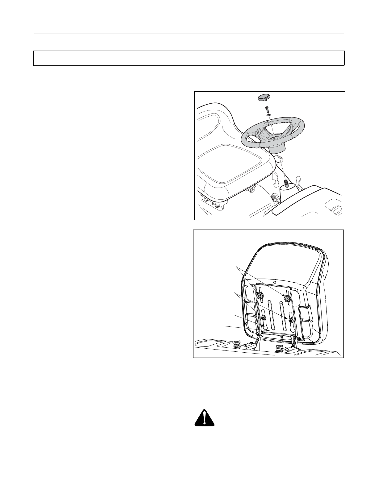
Attaching the Steering Wheel
Tools Required For Assembly
(1) 1/2" socket wrench
1. The hardware for attaching the steering wheel is
located under the steering wheel cap. Carefully pry
off the steering wheel cap and remove the
hardware.
2. Position the front wheels of the tractor so they are
pointing straight forward.
3. Place the washer with the cupped side down over
the steering shaft. Secure with hex bolt. See Figure
1.
4. Place the steering wheel cap over the center of the
steering wheel and seat it with your hand.
3. Select desired position for the seat, and secure with
the two hex screws/knobs removed. Do not
overtighten. See Figure 2.
Figure 1
Knobs
Shoulder
Screws
Opening
in Slot
Pivot
Bracket
Attaching The Seat
NOTE: For shipping reasons, seats are either
fastened to the tractor seat’s pivot bracket with a plastic
tie, or mounted backward to the pivot bracket. In either
case, free the seat form its shipping position and
remove the two hex screws (or knobs, on models so
equipped) from the bottom of seat before proceeding
with instructions below.
1. Position the shoulder screws (found on the base of
the seat) inside the slot openings in the seat pivot
bracket. See Figure 2.
2. Slide the seat slightly rearward in the seat pivot
bracket, lining up the rear slots in the pivot bracket
with the remaining two holes in the seat’s base.
Figure 2
Gas and Oil Fill-up
The gasoline tank is located under the hood and has a
capacity of 1-1/2 gallons. Do not overfill.
WARNING: Use extreme care when
handling gasoline. Gasoline is extremely
flammable and the vapors are explosive.
Never fuel machine indoors or while the
engine is hot or running. Extinguish
cigarettes, cigars, pipes, and other sources of
ignition.
8
Page 9
Service the engine with gasoline and oil as instructed in
the separate engine manual packed with your tractor.
Read instructions carefully.
IMPORTANT:
engine. However, you MUST check the oil level before
operating. Be careful not to overfill.
Your tractor is shipped with motor oil in the
Shipping Brace Removal
WARNING: Make sure the riding mower’s
engine is off, remove the ignition key, and set
the parking brake before removing the
shipping brace
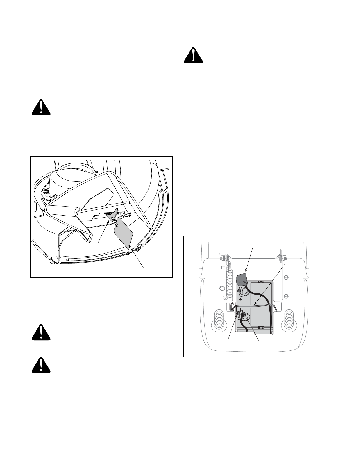
• Locate the shipping brace and accompanying
warning tag found on the right side of the mower,
between the discharge chute and the cutting deck.
See Figure 3.
.
Tire Pressure
WARNING: Maximum tire pressure under
any circumstances is 30 psi. Equal tire
pressure should be maintained at all times.
The tires on your unit may be over-inflated for shipping
purposes. Reduce the tire pressure before operating
the tractor. Recommended operating tire pressure is
approximately 10 p.s.i for the rear tires & 14 p.s.i. for the
front tires. Check sidewall of tire for maximum p.s.i.
Attaching the Battery Cables
NOTE: The positive battery terminal is marked Pos.
(+). The negative battery terminal is marked Neg. (–).
• The positive cable (heavy red wire) is secured to
the positive battery terminal (+) with a hex bolt and
hex nut at the factory. Make certain that the rubber
boot covers the terminal to help protect it from
corrosion.
• Remove the hex bolt and wing nut from the
negative cable.
• Remove the black plastic cover, if present, from the
negative battery terminal and attach the negative
cable (heavy black wire) to the negative battery
terminal (–) with the bolt and wing nut.
• Make certain the retainer rod is in position over the
battery, securing it in place. See Figure 4.
Shipping Brace
Warning Tag
Figure 3
• While holding the discharge chute with your left
hand, remove the shipping brace with your right
hand by grasping it between your thumb and index
finger and rotating it clockwise.
WARNING: The shipping brace, used for
packaging purposes only, must be removed
and discarded before operating your riding
mower.
WARNING: The mowing deck is capable of
throwing objects. Failure to operate the riding
mower without the discharge cover in the
proper operating position could result in
serious personal injury and/or property
damage.
Rubber Boot
Retiner
Rod
Wing Nut
Hex Bolt
Figure 4
NOTE: If the battery is put into service after the date
shown on top of battery, charge the battery as
instructed on page 20 of this manual prior to operating
the tractor.
9
Page 10

SECTION 4: KNOW YOUR LAWN TRACTOR
D
B
A
E
CHOKE
7
6
5
4
3
2
1
P
PARK
BRAKE
FAST
SLOW
C
F
G
Figure 5
A Speed Control Lever / Parking Brake E Ignition Switch Module
B Clutch-brake Pedal F Deck Lift Lever
C Shift Lever G PTO (Blade Engage) Lever
D Throttle Control Lever
NOTE: Any reference in this manual to the RIGHT or LEFT side of the tractor is observed from operator’s position.
10
Page 11
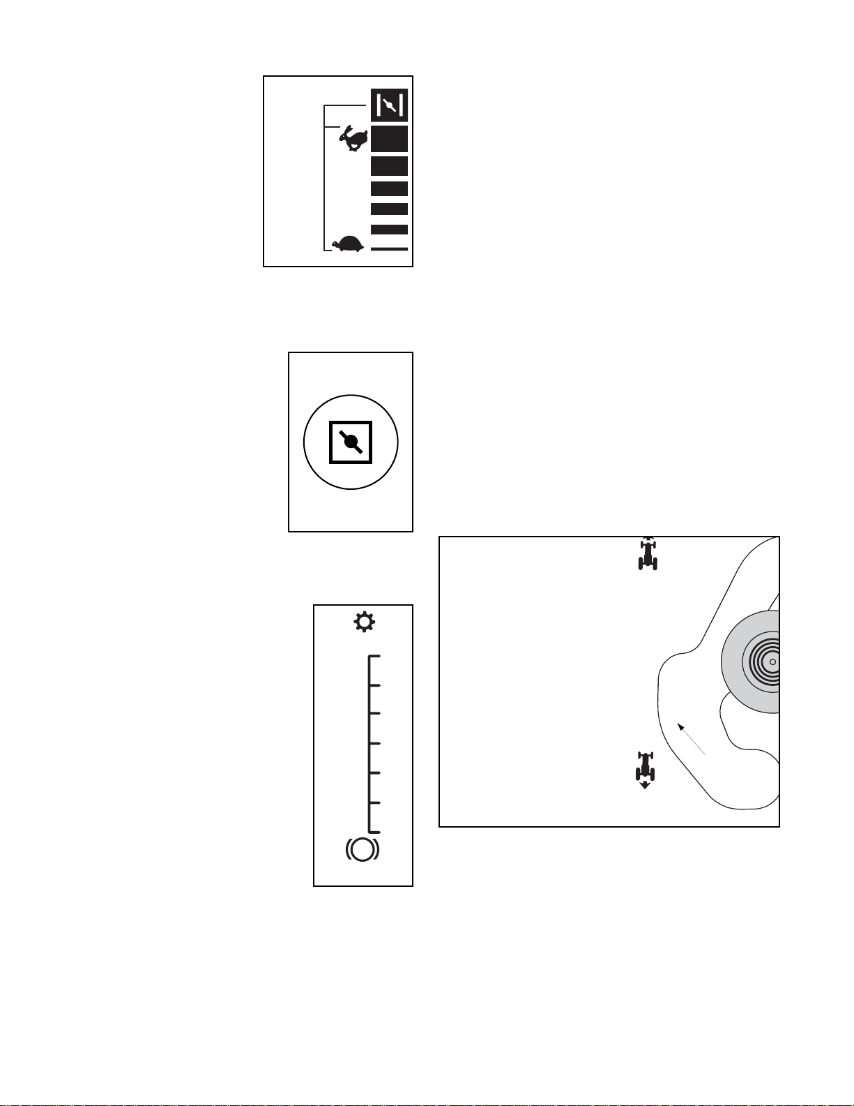
Throttle Control
F
The throttle control lever is
located on the right side of
the tractor’s dash panel. This
lever controls the speed of
the engine and, and on
certain models when pushed
all the way forward, the
choke control also. When set
in a given position, the
throttle will maintain a
uniform engine speed.
IMPORTANT:
deck engaged, be certain that the throttle lever is
always in the FAST (rabbit) position.
When operating the tractor with the cutting
CHOKE
FAS T
SLOW
Choke Control
On some models, moving the
throttle lever all the way forward
activates the engine’s choke
control. On all other models, the
choke control can be found on
the left side of the dash panel and
is activated by pulling the knob
outward. Activating the choke
control closes the choke plate on
the carburetor and aids in starting
the engine. Refer to Starting The Engine in the
OPERATION section of this manual for detailed starting
instructions.
NOTE: The pedal must be depressed to start the
engine. Refer to Safety Interlock Switches on page 13.
Parking Brake
To set the parking brake, fully depress the clutch-brake
pedal. Move the speed control lever all the way down
and into the parking brake position. Release the clutchbrake pedal to allow the parking brake to engage.
To release the parking brake, depress the clutch-brake
pedal and move the speed control lever out of the
notches to the desired position. Release the speed
control lever and the clutch-brake pedal.
NOTE: The parking brake must be set if the operator
leaves the seat with the engine running or the engine
will automatically shut off.
IMPORTANT:
leaving the tractor unattended.
Always set the parking brake when
Shift Lever
The shift lever is located on the left side of the fender
and has three positions, FORWARD, NEUTRAL and
REVERSE. The brake pedal must be depressed and
the tractor must not be in motion when the moving shift
lever. See Figure 6.
AVANT
Speed Control Lever
The speed control lever, located on
the left side of the tractor’s dash
console, allows you to regulate the
ground speed of the lawn tractor. To
use, depress the clutch-brake pedal
and move the lever out of the parking
brake notch and forward to increase
the tractor’s ground speed. When a
desired speed has been reached,
release the lever into an appropriate
notch to maintain that speed.
To slow the tractor’s ground speed,
depress the clutch-brake pedal and
move the speed control lever
rearward and release it into a notch.
7
6
5
4
3
2
1
P
PAR K
BRAKE
Clutch-brake Pedal
The clutch-brake pedal is located on the left side of the
lawn tractor, along the running board. Depress the
clutch-brake pedal part way down when slowing the
tractor by changing speeds (Refer to Speed Control Lever).
Depress the pedal all the way down to engage the disc
brake and bring the tractor to a complete stop.
N
Shift Knob
R
ARRIERE
Figure 6
IMPORTANT:
result in serious damage to the tractor’s transmission.
Never force the shift lever. Doing so may
11
Page 12

Deck Lift Lever
Found on your tractor’s right fender,
the deck lift lever is used to change
the height of the cutting deck. To use,
move the lever to the left, then place
in the notch best suited for your
application.
PTO (Blade Engage) Lever
Found on the tractor’s right fender,
the PTO (blade engage) lever is used
to engage power to the cutting deck
or other (separately available)
attachments. To operate, move the
lever all the way forward. Moving the
lever all the way rearward into the
PTO OFF position disengages power
to the cutting deck/ attachment.
NOTE: The PTO (blade engage)
lever must be in the disengaged
(PTO OFF) position when starting the
engine.
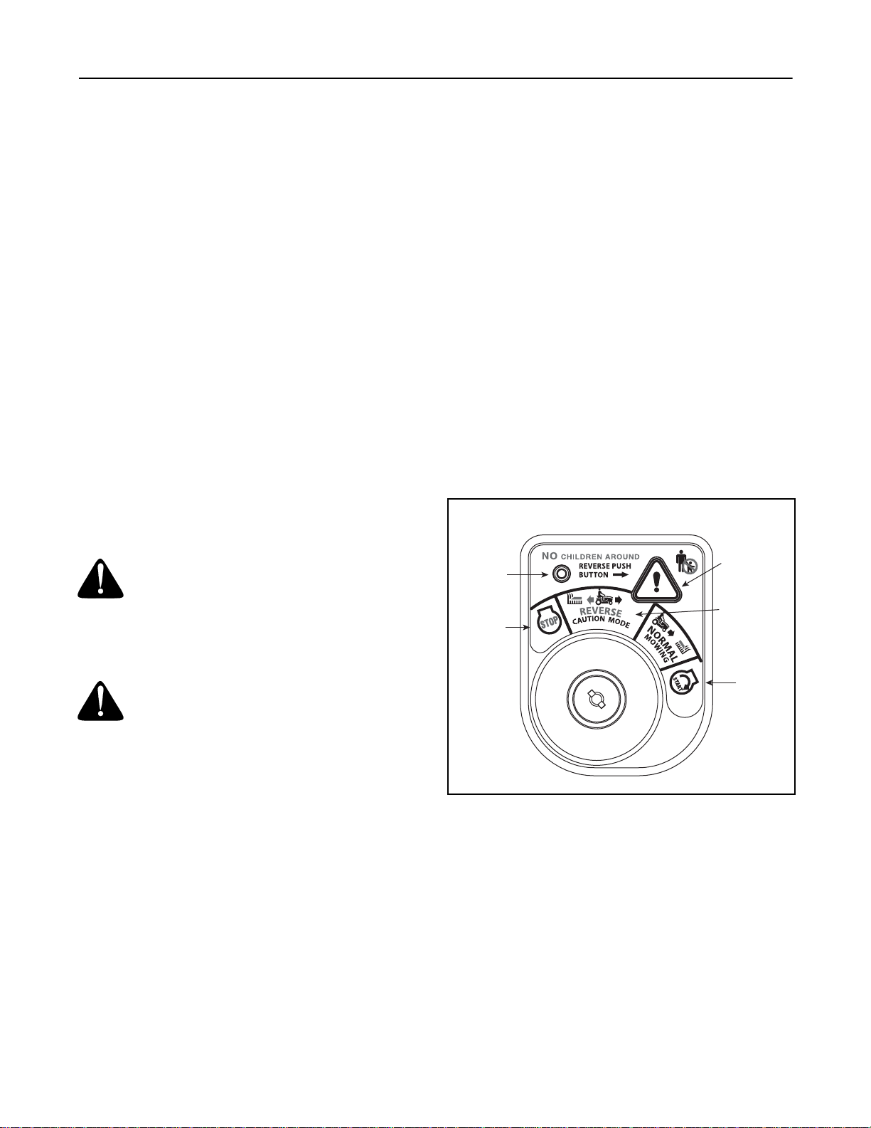
Ignition Switch Module
PTO ON
1
To start the engine, insert the key into the ignition
PTO / BLADE ENGAGE
2
switch and turn clockwise to the START position.
Release the key into the NORMAL MOWING MODE
position once the engine has fired.
To stop the engine, turn the ignition key
counterclockwise to the STOP position. See Figure 7.
3
4
PTO OFF
Stop
Position
WARNING: Never leave a running machine
unattended. Always disengage PTO, move
shift lever into neutral position, set parking
brake, stop engine and remove key to prevent
unintended starting.
Normal
Driving
Mode
Start
Position
5
WARNING
AVOID SERIOUS INJURY OR DEATH
• GO UP AND DOWN SLOPES, NOT ACROSS.
• AVOID SUDDEN TURNS.
• DO NOT OPERATE THE UNIT WHERE IT COULD SLIP OR TIP.
• IF MACHINE STOPS GOING UPHILL, STOP BLADE(S) AND BACK
DOWNHILL SLOWLY.
• DO NOT MOW WHEN CHILDREN OR OTHERS ARE AROUND.
• NEVER CARRY CHILDREN, EVEN WITH BLADES OFF.
• LOOK DOWN AND BEHIND BEFORE AND WHILE BACKING.
• KEEP SAFETY DEVICES (GUARDS, SHIELDS, AND SWITCHES) IN
PLACE AND WORKING.
• REMOVE OBJECTS THAT COULD BE THROWN BY THE BLADE(S).
• KNOW LOCATION AND FUNCTION OF ALL CONTROLS.
• BE SURE BLADE(S) AND ENGINE ARE STOPPED BEFORE PLACING HANDS OR FEET NEAR BLADE(S).
• BEFORE LEAVING OPERATOR’S POSITION, DISENGAGE
BLADE(S), PLACE THE SHIFT LEVER IN NEUTRAL, ENGAGE
BRAKE LOCK, SHUT ENGINE OFF AND REMOVE KEY.
READ OPERATOR’S MANUAL
Figure 7
IMPORTANT:
Safety Interlock Switches on page 13 and Starting The Engine
on page 14 of this manual for detailed instructions
regarding the Ignition Switch Module and operating the
tractor in REVERSE CAUTION MODE.
Prior to operating the tractor, refer to both
12
Page 13
SECTION 5: OPERATING YOUR LAWN TRACTOR
Safety Interlock Switches
This tractor is equipped with a safety interlock system
for the protection of the operator. If the interlock system
should ever malfunction, do not operate the tractor.
Contact an authorized service dealer.
• The safety interlock system prevents the engine
from cranking or starting unless the parking brake is
engaged, and the PTO (Blade Engage) knob (or
lever) is in the disengaged (OFF) position.
• The engine will automatically shut off if the operator
leaves the seat before engaging the parking brake.
• The engine will automatically shut off if the operator
leaves the tractor’s seat with the PTO (Blade
Engage) lever in the engaged (ON) position,
regardless of whether the parking brake is
engaged.
• The engine will automatically shut off if the operator
engages the PTO with the parking brake ON.
• With the ignition key in the NORMAL MOWING
position, the engine will automatically shut off if the
PTO (Blade Engage) lever is moved into the
engaged (ON) position with the shift lever in
Reverse.
WARNING: Do not operate the tractor if the
interlock system is malfunctioning. This
system was designed for your safety and
protection.
Reverse Caution Mode
3. Depress the REVERSE PUSH BUTTON (Orange,
Triangular Button) at the top, right corner of the key
switch module. The red indicator light at the top, left
corner of the key switch module will be ON while
activated. See Figure 8.
4. Once activated (indicator light ON), the tractor can
be driven in reverse with the cutting blades (PTO)
engaged.
5. Always look down and behind before and while
backing to make sure no children are around.
6. After resuming forward motion, return the key to the
NORMAL MOWING position.
IMPORTANT:
remain activated until:
Indicator
Light
Stop
Position
The REVERSE CAUTION MODE will
a. The key is placed in either the NORMAL
MOWING position or STOP position.
b. The operator engages the parking brake by
fully depressing the brake pedal and holding
it down while gently pushing the parking
brake button inward.
Reverse
Push
Button
Reverse
Caution Mode
Position
WARNING: Use extreme caution while
operating the tractor in the REVERSE
CAUTION MODE. Always look down and
behind before and while backing. Do not
operate the tractor when children or others
are around. Stop the tractor immediately if
someone enters the area.
The REVERSE CAUTION MODE position of the key
switch module allows the tractor to be operated in
reverse with the blades (PTO) engaged.
IMPORTANT: Mowing in reverse is not recommended.
To use the REVERSE CAUTION MODE:
IMPORTANT:
tractor seat.
1. Start the engine as previously instructed in this
Operator’s Manual.
2. Turn the key from the NORMAL MOWING
(Green) position to the REVERSE CAUTION
MODE (Yellow) position of the key switch module.
See Figure 8.
The operator MUST be seated in the
Start
Position
Figure 8
Engaging the Parking Brake
To engage the parking brake:
• Fully depress the brake pedal and hold it down with
your foot while gently pushing the parking brake
button inward.
• Hold the parking brake button in while removing
your foot from the brake pedal.
• Once engaged, the parking brake button and the
brake pedal will lock in the “down” position.
To disengage the parking brake:
• Slightly depress the brake pedal.
13
Page 14

NOTE: The parking brake must be set if the operator
leaves the seat with the engine running or the engine
will automatically shut off.
Setting the Cutting Height
Select the height position of the cutting deck by placing
the deck lift lever in any of the five different cutting
height notches on the right side of the fender. Then
adjust the deck wheels, if so equipped, so that they are
between ¼-inch and ½-inch above the ground when the
tractor is on a smooth, flat surface such as a driveway.
WARNING: Keep hands and feet away
from the discharge opening of the cutting
deck.
NOTE: On models so equipped, the deck wheels are
an anti-scalp feature of the deck and are not designed
to support the weight of the cutting deck.
Refer to Making Adjustments this manual for more detailed
instructions regarding various deck adjustments.
Stopping the Engine
WARNING: If you strike a foreign object,
stop the engine, disconnect the spark plug
wire(s) and ground against the engine.
Thoroughly inspect the machine for any
damage. Repair the damage before restarting
and operating
• If the blades are engaged, place the PTO (Blade
Engage) knob (or lever) in the disengaged (OFF)
position.
• Turn the ignition key counterclockwise to the OFF
position.
• Remove the key from the ignition switch to prevent
unintended starting.
Driving the Tractor
WARNING: Avoid sudden starts, ex-
cessive speed and sudden stops.
Starting the Engine
WARNING: Do not operate the tractor if the
interlock system is malfunctioning. This
system was designed for your safety and
protection.
NOTE: Refer to the TRACTOR SET-UP on page 8 of this
manual for Gasoline and Oil fill-up instructions.
• Insert the tractor key into the ignition switch.
• Place the PTO (Blade Engage) knob (or lever) in
the disengaged (OFF) position.
• Engage the tractor’s parking brake.
• Activate the choke control.
• Turn the ignition key clockwise to the START
position. After the engine starts, release the key. It
will return to the ON position.
IMPORTANT:
position for longer than ten seconds at a time. Doing so
may cause damage to your engine’s electric starter.
• After the engine starts, deactivate the choke control
and place the throttle control in the FAST position.
NOTE: Do NOT leave the throttle control in the
CHOKE position while operating the tractor. Doing so
will result in a "rich" fuel mixture and cause the engine
to run poorly.
Do NOT hold the key in the START
WARNING: Do not leave the seat of the
tractor without first placing the PTO (Blade
Engage) lever in the disengaged (OFF)
position, depressing the brake pedal and
engaging the parking brake. If leaving the
tractor unattended, also turn the ignition key
off and remove the key.
WARNING: Always look down and behind
before and while backing up to avoid a backover accident.
• Depress the brake pedal to release the parking
brake and let the pedal up.
• Move the throttle lever into the FAST (rabbit)
position.
• Place the shift lever in either the FORWARD or
REVERSE position.
IMPORTANT:
direction of travel when the tractor is in motion. Always
use the brake pedal to bring the tractor to a complete
stop before shifting.
• Release the parking brake by depressing the
clutch-brake pedal and positioning the speed
control lever in desired position.
IMPORTANT:
positions 1 or 2. Become completely familiar with the
tractor’s operation and controls before operating the
tractor in higher speed positions.
Do NOT use the shift lever to change the
First-time operators should use speed
• Release clutch-brake pedal slowly to put unit into
motion.
• The lawn tractor is brought to a stop by depressing
the clutch-brake pedal.
14
Page 15

NOTE: When operating the unit initially, there will be
little difference between the highest two speeds until
after the belts have seated themselves into the pulleys
during the break-in period.
To raise the cutting deck, move the deck lift lever to the
left, then place it in the notch best suited for your
application. Refer to Setting The Cutting Height earlier in
this section.
WARNING: Before leaving the operator’s
position for any reason, disengage the
blades, place the shift lever in neutral,
engage the parking brake, shut engine off
and remove the key.
IMPORTANT:
while on a grass surface, always
• Place the shift lever in neutral,
• Engage the parking brake,
• Shut engine off and remove the key.
Doing so will minimize the possibility of having your
lawn ‘‘browned’’ by hot exhaust from your tractor’s
running engine.
If unit stalls with speed control in high speed, or if unit
will not operate with speed control lever in a low speed
position, proceed as follows.
• Place shift lever in NEUTRAL.
• Restart engine.
• Place speed control lever in highest speed position.
• Release clutch-brake pedal fully.
• Depress clutch-brake pedal.
• Place speed control lever in desired position.
• Place shift lever in either FORWARD or REVERSE,
and follow normal operating procedures.
When stopping the tractor for any reason
Engaging the Blades
Engaging the PTO (Blade Engage) transfers power to
the cutting deck or other (separately available)
attachments. To engage the blades, proceed as
follows:
• Move the throttle control lever to the FAST (rabbit)
position.
• Grasp the PTO (Blade Engage) lever and position it
all the way forward into the engaged (ON) position.
• Keep the throttle lever in the FAST (rabbit) position
for the most efficient use of the cutting deck or other
(separately available) attachments
IMPORTANT:
PTO is engaged with the shift lever in position for
reverse travel with the ignition key in the NORMAL
MOWING position. Refer to Safety Interlock Switches on
page 13.
The engine will automatically shut off if the
Mowing
WARNING: To help avoid blade contact or
a thrown object injury, keep bystanders,
helpers, children and pets at least 75 feet
from the machine while it is in operation. Stop
machine if anyone enters the area.
Driving on Slopes
Refer to the SLOPE GAUGE on page 7 to help determine
slopes where you may operate the tractor safely.
WARNING: Do not mow on inclines with a
slope in excess of 15 degrees (a rise of
approximately 2-1/2 feet every 10 feet). The
tractor could overturn and cause serious
injury.
• Mow up and down slopes, NEVER across.
• Exercise extreme caution when changing direction
on slopes.
• Watch for holes, ruts, bumps, rocks, or other
hidden objects. Uneven terrain could overturn the
machine. Tall grass can hide obstacles.
• Avoid turns when driving on a slope. If a turn must
be made, turn down the slope. Turning up a slope
greatly increases the chance of a roll over.
• Avoid stopping when driving up a slope. If it is
necessary to stop while driving up a slope, start up
smoothly and carefully to reduce the possibility of
flipping the tractor over backward.
Using the Deck Lift Lever
The following information will be helpful when using the
cutting deck with your tractor.
WARNING: Plan your mowing pattern to
avoid discharge of materials toward roads,
sidewalks, bystanders and the like. Also,
avoid discharging material against a wall or
obstruction which may cause discharged
material to ricochet back toward the operator.
• Do not mow at high ground speed, especially if a
mulch kit or grass collector is installed.
• For best results it is recommended that the first two
laps be cut with the discharge thrown towards the
center. After the first two laps, reverse the direction
to throw the discharge to the outside for the
balance of cutting. This will give a better
appearance to the lawn.
• Do not cut the grass too short. Short grass invites
weed growth and yellows quickly in dry weather.
• Mowing should always be done with the engine at
full throttle.
• Under heavier conditions it may be necessary to go
back over the cut area a second time to get a clean
cut.
15
Page 16

• Do NOT attempt to mow heavy brush and weeds
and extremely tall grass. Your tractor is designed to
mow lawns, NOT clear brush.
• Keep the blades sharp and replace the blades
when worn. Refer to Cutting Blades on page 20 of this
manual for proper blade sharpening instructions.
SECTION 6: MAKING ADJUSTMENTS
Headlights
On some models, the lamps are ON whenever the
tractor’s engine is running. On other models, the lamps
are ON whenever the ignition key is moved out of the
STOP position.
On all models, the lamps turn OFF when the ignition
key is moved to the STOP position.
WARNING: Never attempt to make any
adjustments while the engine is running,
except where specified in the operator’s
manual.
Leveling the Deck
NOTE: Check the tractor’s tire pressure before
performing any deck leveling adjustments. Refer to
Tires on page 20 for information regarding tire pressure.
Front To Rear
The front of the cutting deck is supported by a stabilizer
bar that can adjusted to level the deck from front to rear.
The front of the deck should be between 1/4-inch and
3/8-inch lower than the rear of the deck. Adjust if
necessary as follows:
• With the tractor parked on a firm, level surface,
place the deck lift lever in the top notch (highest
position) and rotate the blade nearest the discharge
chute so that it is parallel with the tractor.
• Measure the distance from the front of the blade tip
to the ground and the rear of the blade tip to the
ground.
• The first measurement taken should be between
1/4" and 3/8" less than the second measurement.
Determine the approximate distance necessary for
proper adjustment and proceed, if necessary.
• Locate the jam nut and lock nut found on the front
side of the stabilizer bracket. See Figure 9. After
loosening the jam nut:
Tighten the lock nut to raise the front of the deck;
Loosen the lock nut to lower the front of the deck.
Figure 9
• Retighten the jam nut loosened earlier after proper
adjustment is achieved.
Side to Side
If the cutting deck appears to be mowing unevenly, a
side to side adjustment can be performed. Adjust if
necessary as follows:
• With the tractor parked on a firm, level surface,
place the deck lift lever in the top notch (highest
position) and rotate both blades so that they are
perpendicular with the tractor.
• Measure the distance from the outside of the left
blade tip to the ground and the distance from the
outside of the right blade tip to the ground. Both
measurements taken should be equal. If they’re
not, proceed to the next step.
16
Page 17

• Loosen, but do NOT remove, the hex screw on the
left deck hanger bracket. See Figure 10.
Hex Screw
Adjustment Gear
Figure 10
• Balance the deck by using a wrench to turn the
adjustment gear (found immediately behind the hex
cap screw just loosened) clockwise/up or
counterclockwise/down.
• The deck is properly balanced when both blade tip
measurements taken earlier are equal.
• Retighten the hex cap screw on the left deck
hanger bracket when proper adjustment is
achieved.
Parking Brake Adjustment
WARNING: Never attempt to adjust the
brakes while the engine is running. Always
disengage PTO, move shift lever into neutral
position, stop engine and remove key to
prevent unintended starting.
If the tractor does not come to a complete stop when
the brake pedal is completely depressed, or if the
tractor’s rear wheels can roll with the parking brake
applied, the brake is in need of adjustment. The brake
disc can be found on the right side of the transmission
in the rear of the tractor. Adjust if necessary as follows:
• Looking at the transmission from the right side of
the tractor, locate the compression spring and
brake disc. See Figure 11.
Hex Nut
Compression Spring
Brake
Puck
• Loosen, but do NOT remove, the hex nut found on
the right side of the brake assembly. See Figure 11.
• Re-tighten the hex nut, allowing a gap of .011"
between the brake disc and the brake puck. Use a
feeler gauge to achieve a precise measurement.
Brake Disc
Figure 11
Transmission
Seat Adjustment
To adjust the position of the seat, loosen the two knobs
on the bottom of the seat. See Figure 12. Slide the seat
forward or backward as desired. Retighten the two
knobs.
Knobs
17
Figure 12
Page 18

SECTION 7: MAINTAINING YOUR LAWN TRACTOR
WARNING: Before performing any
maintenance or repairs, disengage PTO,
move shift lever into neutral position, set
parking brake, stop engine and remove key to
prevent unintended starting.
Engine
Refer to the separate engine manual for engine
maintenance instructions.
Check engine oil level before each use as instructed in
the separate engine manual packed with your unit.
Follow the instructions carefully.
Changing Engine Oil
NOTE: Depending on the engine model found on your
tractor, it may be necessary to remove the tractor’s side
panel in order to replace the oil filter (if so equipped).
Changing Engine Oil
For draining oil from the engine’s crankcase of select
model tractors, a plastic oil drain sleeve is packed with
this Operator’s Manual. To drain the oil, proceed as
follows:
• Unscrew the oil fill cap and remove the dipstick
from the oil fill tube.
• Snap the small end of oil drain sleeve onto the oil
sump. See Figure 13.
• Service the oil filter (if so equipped) as instructed
in the separate engine manual packed with your
unit.
Perform the above steps in the opposite order after oil
has finished draining.
• Refill the engine with new motor oil.
IMPORTANT:
packed with your unit for information regarding the
quantity and proper weight of motor oil.
Refer to the separate engine manual
Air Cleaner
To service the air cleaner, refer to the separate engine
manual packed with your unit
Fuel Filter
Service the fuel filter, if so equipped, as instructed in the
separate engine manual packed with your unit.
Spark Plug(s)
The spark plug(s) should be cleaned and the gap reset
once a season. Spark plug replacement is
recommended at the start of each mowing season.
Refer to the separate engine manual for correct plug
type and gap specifications.
Lubrication
WARNING: Before lubricating, repairing, or
inspecting, always disengage PTO, move
shift lever into neutral position, set parking
brake, stop engine and remove key to prevent
unintended starting.
Oil Drain Sleeve
Figure 13
• Remove drain plug and drain oil into a suitable
container with a capacity of no less than 64 oz.
Engine
Lubricate the engine with motor oil as instructed in the
separate engine manual packed with your unit.
Pivot Points & Linkage
Lubricate all the pivot points on the drive system,
parking brake and lift linkage at least once a season
with light oil.
Rear Wheels
The rear wheels should be removed from the axles
once a season. Lubricate the axles and the rims well
with an all-purpose grease before re-installing them.
Front Axles
Each end of the tractor’s front pivot bar may be
equipped with a grease fitting. Lubricate with a grease
gun after every 25 hours of tractor operation.
18
Page 19

Cleaning the Engine and Deck
Any fuel or oil spilled on the machine should be wiped
off promptly. Do NOT allow debris to accumulate
around the cooling fins of the engine or on any other
part of the machine.
IMPORTANT:
your tractor is NOT recommended. It may cause
damage to electrical components, spindles, pulleys,
bearings or the engine.
The use of a pressure washer to clean
Deck Wash System™
A hex plug can be found on your tractor’s deck surface.
See Figure 14.
This plug can be replaced with a water port to be used
as part of a separately-available deck wash system.
Use the Deck Wash System™ to rinse grass clippings
from the deck’s underside and prevent the buildup of
corrosive chemicals.
NOTE: Refer to page 23 for information regarding this
and other separately-available attachments &
accessories for your tractor.
SECTION 8: SERVICE
Cutting Deck Removal
To remove the cutting deck, proceed as follows:
• Place the PTO (Blade Engage) lever in the
disengaged (OFF) position.
• Engage the parking brake.
• Lower the deck by moving the deck lift lever into the
bottom notch on the right fender.
• Remove the belt from around the tractor’s engine
pulley and idler pulley(s). Refer to Changing the Deck
Belt on page 21 for detailed instructions. See Figure
20.
• Looking at the cutting deck from the left side of the
tractor, locate the hair pin clip that secures the deck
support rod on the rear left side of the deck. See
Figure 15.
• Remove the hair pin clip that secures the deck
support rod, and carefully remove the deck support
from the deck lift arm.
• Repeat the above steps on the tractor’s right side.
• Move the deck lift lever into the top notch on the
right fender to raise the deck lift arms up and out of
the way.
• Carefully remove the PTO cable from the rear of
the cutting deck by removing the hair pin clip which
Hex Plug
Figure 14
secures it. Proceed to remove the spring from the
deck idler bracket. See Figure 16.
• Gently slide the cutting deck toward the front of the
tractor allowing the hooks on the deck to release
themselves from the deck stabilizer rod.
• Gently slide the cutting deck (from the right side)
out from underneath the tractor.
Hair Pin Clip
Figure 15
19
Page 20

Idler Bracket
Hair Pin Clip
PTO Cable
Figure 16
Tires
WARNING: Never exceed the maximum
inflation pressure shown on the sidewall of the
tire.
The recommended operating tire pressure is:
• Approximately 10 psi for the rear tires.
• Approximately 14 psi for the front tires.
IMPORTANT:
manufacturer’s recommended or maximum psi. Do not
overinflate. Uneven tire pressure could cause the
cutting deck to mow unevenly.
Refer to the tire sidewall for exact tire
Battery
The battery is sealed and is maintenance-free. Acid
levels cannot be checked.
• Always keep the battery cables and terminals clean
and free of corrosive build-up.
• After cleaning the battery and terminals, apply a
light coat of petroleum jelly or grease to both
terminals.
• Always keep the rubber boot positioned over the
positive terminal to prevent shorting.
IMPORTANT:
disconnect the NEGATIVE (Black) wire from it’s
terminal first, followed by the POSITIVE (Red) wire.
When re-installing the battery, always connect the
POSITIVE (Red) wire its terminal first, followed by the
NEGATIVE (Black) wire. Be certain that the wires are
connected to the correct terminals; reversing them
could change the polarity and result in damage to your
engine’s alternating system.
If removing the battery for any reason,
Charging
If the tractor has not been put into use for an extended
period of time, charge the battery with an automotivetype 12-volt charger for a minimum of one hour at six
amps.
WARNING: Batteries give off an explosive
gas while charging. Charge battery in a well
ventilated area and keep away from an open
flame or pilot light as on a water heater, space
heater, furnace, clothes dryer or other gas
appliances.
Jump Starting
WARNING: When removing or installing
the battery, follow these instructions to
prevent the screwdriver from shorting against
the frame.
IMPORTANT:
with the battery of a running vehicle.
• Connect end of one jumper cable to the positive
terminal of the good battery, then the other end to
the positive terminal of the dead battery.
• Connect the other jumper cable to the negative
terminal of the good battery, then to the frame of
the unit with the dead battery.
Never jump your tractor’s dead battery
WARNING: Failure to use this procedure
could cause sparking, and the gas in either
battery could explode.
Cleaning
Clean the battery by removing it from the tractor and
washing with a baking soda and water solution. If
necessary, scrape the battery terminals with a wire
brush to remove deposits. Coat terminals and exposed
wiring with grease or petroleum jelly to prevent
corrosion.
Battery Failures
Some common causes for battery failure are:
• freezing • undercharging
• overcharging • corroded connections
These failures are NOT covered by your tractor’s
warranty.
Fuse
One 20 AMP fuse is installed in your tractor’s wiring
harness to protect the tractor’s electrical system from
damage caused by excessive amperage.
If the electrical system does not function, or your
tractor’s engine will not crank, first check to be certain
that the fuse has not blown. It can be found under the
hood mounted behind the dash panel on the right side.
20
Page 21

WARNING: Always use a fuse with the
same amperage capacity for replacement.
Cutting Blades
WARNING: Be sure to shut the engine off,
remove ignition key, disconnect the spark plug
wire(s) and ground against the engine to
prevent unintended starting before removing
the cutting blade(s) for sharpening or
replacement. Protect your hands by using
heavy gloves or a rag to grasp the cutting
blade.
WARNING: Periodically inspect the blade
spindles for cracks or damage, especially if
you strike a foreign object. Replace
immediately if damaged
The blades may be removed as follows.
• Remove the deck from beneath the tractor, (refer to
Cutting Deck Removal on page 19) then gently flip the
deck over to expose its underside.
• Place a block of wood between the center deck
housing baffle and the cutting blade to act as a
stabilizer. See Figure 17.
• Use a 15/16" wrench to remove the hex flange nut
that secures the blade to the spindle assembly. See
Figure 17.
Hex Flange Nut
.
Wood Block
Blade Separation
Worn Blade Edge
Wind Wing
5
/
8
"
m
i
n
i
m
u
m
Sharpen Edge Evenly
Figure 18
It is important that each cutting blade edge be ground
equally to maintain proper blade balance.
A poorly balanced blade will cause excessive vibration
and may cause damage to the tractor and result in
personal injury. The blade can be tested by balancing it
on a round shaft screwdriver. Grind metal from the
heavy side until it balances evenly.
When replacing the blade, be sure to install the blade
with the side of the blade marked ‘‘Bottom’’facing the
ground when the mower is in the operating position.
IMPORTANT:
spindle hex flange nut to between 70 foot-pounds and
90 foot-pounds.
Use a torque wrench to tighten the blade
Spindle Assembly
Figure 17
IMPORTANT:
already been sharpened to within 5/8" of the wind wing
radius, or if any metal separation is present, replace the
blades with new ones. See Figure 18.
. If the cutting edge of the blade has
Changing the Transmission Drive Belts
NOTE: Several components must be removed and
special tools (i.e. air/impact wrench) in order to change
the tractor’s drive belts. See an authorized Troy-Bilt
Service Dealer to have your drive belts replaced or
phone Customer Support as instructed on page 2 for
information on ordering a Service Manual.
Changing the Deck Belt
WARNING: Be sure to shut the engine off,
remove ignition key, disconnect the spark
plug wire(s) and ground against the engine to
prevent unintended starting before removing
the belt(s).
WARNING: Avoid the possibility of a
pinching injury. Do not place your fingers on
the idler spring or between the belt and a
pulley while removing the belt.
21
Page 22

All belts on your tractor are subject to wear and should
be replaced if any signs of wear are present.
IMPORTANT:
The V-belts found on your tractor are
specially designed to engage and disengage safely. A
substitute (non-OEM) V-belt can be dangerous by not
disengaging completely. For a proper working machine,
use factory approved belts.
To change or replace the deck belt on your tractor,
proceed as follows:
• Lower the deck by moving the deck lift lever into the
bottom notch on the right fender.
• Remove the belt guards by removing the self-
tapping screws that fasten them to the deck.
• Remove the belt keeper rod from around the
engine pulley.
Belt Guard
Idler Bracket
3/8” Square Hole
• Insert a 3/8”-drive ratchet wrench (set to loosen)
into the square hole found in the idler bracket on
the left side of the deck’s surface. See Figure 19.
• Grasp the ratchet’s handle and pivot it toward the
front of the tractor to relieve tension on the belt.
• With belt tension relieved, carefully remove the
belt from around the left-hand spindle pulley.
Idler Bracket
Figure 19
IMPORTANT:
Carefully allow the ratchet to pivot
rearward before removing it from the square hole.
• Remove the deck belt from around all pulleys,
including the deck idler pulley.
• Route the new belts (deck belt first).
• Remount the belt guards removed earlier.
Engine Pulley
Right Hand Pulley
(beneath belt guard)
Left Hand Pulley
(beneath belt guard)
Deck Idler Pulleys
Figure 20
22
Page 23

SECTION 9: OFF-SEASON STORAGE
Clean and lubricate the tractor as instructed in Section 7:
MAINTAINING YOUR LAWN TRACTOR on page 18 of this
manual before storing for an extended period.
Follow the instructions in the Service, Storage &
Specifications section of the separate engine manual
for proper engine care prior to storing your tractor.
WARNING: Drain fuel only into an
approved container outdoors, away from an
open flame. Allow engine to cool. Extinguish
cigarettes, cigars, pipes, and other sources of
ignition prior to draining fuel.
WARNING: Never store the machine or
fuel container indoors where there is an open
flame, spark or pilot light such as on water
heater, furnace, clothes dryer or other gas
appliance.
SECTION 10: ATTACHMENTS & ACCESSORIES
The following attachments and accessories are compatible for 700-Series Lawn Tractors. See the retailer from
which you purchased your tractor or an authorized Service Dealer for information regarding price and availability.
NOTE: Model Series 700 Lawn Tractors are NOT designed for use with any type of ground-engaging attachments
(e.g. tiller or plow). Use of this type of equipment WILL void the tractor’s warranty.
MODEL DESCRIPTION
OEM-190-116 38- and 42-inch Deck Mulch Kit
OEM-190-672 Grille Guard (mounts on front of tractor)
OEM-190-180 Twin Bagger Grass Collector
OEM-190-184 Dethatcher
OEM-190-218 Rear Wheel Weights
OEM-190-658 Tire Chains
OEM-190-032 42-inch Two-stage Snow Thrower
OEM-190-833 46-inch Front Dozer Blade
490-900-0024 Deluxe Tractor Sunshade
490-900-0025 Deck Wash Kit
* Not compatible with tractors equipped with a Grass Collector
23
Page 24

SECTION 11: TROUBLESHOOTING
Trouble Possible Cause(s) Corrective Action
Engine fails to start PTO engaged.
Parking brake not engaged.
Spark plug wire(s) disconnected.
Throttle control lever not in correct
starting position.
Choke not activated.
Place PTO lever in disengaged (OFF) position.
Engage parking brake.
Connect wire(s) to spark plug(s).
Place throttle control in CHOKE position.
Place the throttle control in CHOKE position.
Fuel tank empty, or stale fuel.
Blocked fuel line.
Faulty spark plug.
Engine flooded.
Engine runs erratic Unit running with CHOKE applied.
Spark plug wire(s) loose.
Blocked fuel line or stale fuel.
Vent in gas cap plugged.
Water or dirt in fuel system.
Dirty air cleaner.
Engine overheats Engine oil level low.
Air flow restricted.
Engine hesitates at high RPM Spark plug(s) gap too close. Remove spark plug(s) and reset the gap.
Idles poorly Spark plug(s) fouled, faulty or gap too
wide.
Dirty air cleaner.
Excessive vibration Cutting blade loose or unbalanced.
Damaged or bent cutting blade.
Mower will not mulch grass Engine speed too low.
Wet grass.
Excessively high grass.
Dull blade.
Uneven cut Deck not balanced properly.
Dull blade.
Uneven tire pressure.
Fill tank with clean, fresh (less than 30 days old) gas.
Clean fuel line or replace fuel filter, if so equipped.
Clean, adjust gap or replace plug.
Crank engine with throttle in FAST position.
Move the throttle control out of the CHOKE position.
Connect and tighten spark plug wire(s).
Clean fuel line; fill tank with clean, fresh (less than 30
days old) gasoline. Replace fuel filter, if so equipped.
Clear vent or replace cap if damaged.
Drain fuel tank. Refill with clean, fresh (less than 30
days old) gasoline.
Replace air cleaner cartridge/element or clean precleaner, if so equipped.
Fill crankcase with proper capacity and weight of oil.
Clean grass clippings and debris from around the
engine’s cooling fins and blower housing.
Replace spark plug(s). Set plug(s) gap.
Replace air cleaner cartridge/element or clean precleaner, if so equipped.
Tighten blade and spindle. Balance blade.
Replace blade.
Place throttle control in FAST (rabbit) position.
Do not mow when grass is wet; wait until later to cut.
Mow once at a high cutting height, then mow again at
desired height or make a narrower cutting swath.
Sharpen or replace blade.
Perform side-to-side deck adjustment.
Sharpen or replace blade.
Check tire pressure in all four tires.
24
Page 25

SECTION 12: THREE YEAR LIMITED WARRANTY
For three (3) years from the date of original purchase of our products, we will eithe r repair or replace, at its
option, free of charge, F.O.B. Factory or authorized service firm, any part found to be DEFECTIVE IN
MATERIAL and WORKMANSHIP for the original purchaser. all transportation charges on parts
submitted for replacement under this warranty must be paid by the purchaser unless return is requested
by the manufacturer.
This warranty DOES NOT apply to any part which has become inoperative through misuse, excessive
use, accident, neglect, improper maintenance or alterations by unauthorized persons.
The limited warranty does not extend to the replacement of parts which are not defective, but where
regular usage has exhausted the life of the part.
ENGINES, ELECTRIC START KITS, PEERLESS TRANSMISSIONS AND PEERLESS TRANSAXLES
ARE WARRANTED BY THEIR RESPECTIVE MANUFACTURER. ALL CLAIMS AGAINST THESE
COMPONENTS MUST BE HANDLED THROUGH THE RESPECTIVE MANUFACTURER’S SERVICE
DEALERS.
Belts, light bulbs, clutch parts (friction wheels), grass bags, tires, seats, rider deck wheels and cutting
blades are covered by a 60 day limited warranty.
Batteries are covered by a 90 day limited warranty.
Fuses, shear bolts and blade adapters are considered consumable items and as such are not warranted.
NOTE: Regular maintenance replacement parts and related inspections and adjustments are excluded
from coverage when made as part of normal maintenance service.
TRACTOR ATTACHMENT WARRANTY
Mower decks included with your product, or sold separately, as an attachment for your garden tractors
will be warranted according to the above terms of the manufacturer three (3) year limited consumer
warranty.
ALL OTHER ATTACHMENTS will be sold under the same condition as above except the warranty will be
ONE YEAR FROM DATE OF ORIGINAL PURCHASE.
PERSONAL USE
THE FOREGOING PARAGRAPHS CONSTITUTE THE MANUFACTURER’S ENTIRE WARRANTY
WITH RESPECT TO ANY PRODUCT PURCHASED AND USED FOR PERSONAL FAMILY,
HOUSEHOLD/RESIDENTIAL PURPOSES, AS DISTINGUISHED FROM COMMERCIAL USAGE.
COMMERCIAL USE
ALL APPLICATIONS OTHER THAN PERSONAL USE AS OUTLINED ABOVE, ARE CONSIDERED
COMMERCIAL USAGE.
New products purchased for commercial usage are warranted in the same manner and to the same
extend EXCEPT the term of warranty will be 60 DAYS from date of purchase.
WARRANTY SERVICE CAN ONLY BE PERFORMED BY AN AUTHORIZED SERVICE DEALER. ANY
NON-ORIGINAL EQUIPMENT REPLACEMENT PART USED ON OR IN A PRODUCT UNDER
WARRANTY WILL BE EXCLUDED FROM THAT WARRANTY COVERAGE, AS WILL BE ANY
RELATED DAMAGED COMPONENTS RESULTING FROM THE INSTALLATION OF A
REPLACEMENT PART FROM ANOTHER SOURCE OTHER THAN THE MANUFACTURER.
25
Page 26

Models/Modèles 760
13
19
& 770
11
6
1
12
A
29
17
33
3
20
9
3018
8
14
6
2
15
26
25
7
24
23
27
32
31
28
3
4
A
16
2
22
21
10
26
5
Page 27

REF PAR T
NO. NO.
N° DE N° DE
RÉF PIÈCE DE SCRIP TION DE SCRIP TION
1 731-1097F Grille Grille
2 710-0599 Hex Wash S-Tapp Scr 1/4-20 x .50 Vis autotaraudeuse à rondelle hex. 1/4-20 x 0,50
3 710-0642 Thd Form ing Scr. 1/4-20 x .75 Lg. Vis taraudée 1/4-20 x 0,75 lg.
4 712-0185 “U” Type Speed Nut Écrou en “U”
5 712-04063 Flange Locknut 5/16-18 Gr. F, Ny lon Contre-écrou à embase 5/16-18 Qual. F, ny lon
6 712-04064 Hex L-Flanged Nut 1/4-20 Gr. F, Ny lon Contre-écrou à embase 1/4-20 Qual. F, ny lon
7 726-04012 Push Nut Écrou à enfoncer
8 728-0162 Rivet, Flat Head 1/4" Rivet, tête plate, 1/4 po
9 731-05012 Col lar, Dash, Style 0 Col lier de tab leau de bord, style 0
10 731-1099A Lens - Style “0" Lentille - Style 0
11 738-0952A Shoul der Screw .375 x .125, 1/4-20 Vis à épaulement 0,375x 0,125, 1/4-20
12 749-0722C Grille Sup port Rod Tige de sup port de la grille
13 783-04608 Hood Capot
14 683-04189 Dash As sem bly Tab leau de bord
15 710-0607 Hex Wash HD S-Tapp Scr 5/16-18 x .50 Vis auto-taraudeuse hex ag o nal 5/16-18 x 0,50
16 710-0895 Hex Tapp Scr 1/4 x .75" Lg. Vis taraudée à tête hex. de 1/4 x 0,75 po de lg.
17 710-3217 Torx Screw, #8-32 x .375 Vis Torx N° 8-32 x 0,375 po
18 712-0142 Hex Nut #8-32, 0.375 Écrou hex. N° 8-32, 0,375
19 731-04945 Steer ing Sup port Sup port de di rec tion
20 731-1857 Throt tle Con trol Le ver Manette de l’obturateur
21 725-0963 Min ia ture Lamp 12V Socket Type Am poule min ia ture 12V
22 725-1649 Socket Douille
23 726-0201 Push Speed Nut Écrou rapide d’enfoncer
24 738-04015 Shoul der Screw, 5/16-18 x .625 Vis à épaulement, 5/16-18 x 0,625
25 726-0230 Ca ble Tie Attache câble
26 751-0555B Fuel Tamk 1.5 gal. Réservoir de car bu rant 1,50 gal.
27 751-0603 Cap-Fuel Capuchon d’essence
28 725-04227 Ig ni tion Switch-Do mes tic Mod ule Commutateur d’allumage - mod ule domestique
29 725-1744 Ig ni tion Key w/o Plas tic Cover Clé de con tact sans capuchon en plastique
30 746-1085A Choke Ca ble 37.5" Lg. Câble de volet de départ 37,50 po de lg.
31 731-1999 Choke Plug Bouchon - volet de départ
32 710-1017 Torx Mach. AB-Tapp Scr. Vis torx AB 1/4-14 x 0,625 po de lg.
1/4-14 x .625 Lg
33 746-1084 Choke/Throt tle Ca ble (Intek Sin gle) Câble de l’obturateur/volet de départ
(Intek monocylindre)
33 746-1086 Throt tle Ca ble (Intek Twin) Câble de l’obturateur (moteur Intek
cylindres jumelés)
13A-760
12.14.04
27
Page 28

Model
s/Modèles 761 & 771
12
19
22
20
31
28
3
13
6
4
9
21
29
11
30
27
25
1
24
15
26
8
7
16
10
32
17
23
18
1
?
14
2
28
Page 29

REF PAR T
NO. NO.
N° DE N° DE
RÉF PIÈCE DE SCRIP TION DE SCRIP TION
1 710-0599 Hex Wash S-Tapp Scr 1/4-20 x .50 Vis autotaraudeuse à rondelle hex.
1/4-20 x 0,50
2 710-0726 Hex Wash HD AB Tap Scr 5/16-12 x .75 Vis taraudée 5/16-12 x 0,75
3 710-0751 Hex Bolt 1/4-20 x .62 Gr. 5 Boulon hexagonale 1/4-20 x 0,62 Qual. 5
4 710-1652 Hex Wash Hd TT Scr. 1/4-20 x .625 Vis taraudée 1/4-20 x 0,625
5 712-0185 “U” Type Speed Nut Écrou en «U»
6 712-04064 Hex L-Flanged Nut 1/4-20 Gr. F, Ny lon Contre-écrou à embase 1/4-20 Qual. F, ny lon
7 725-0963 Min ia ture Lamp 12V Socket Type Am poule min ia ture 12V
8 725-1649 Socket Douille
9 731-04947 Dash Col lar Col lier de tab leau de bord
10 731-04949 Lens Lentille
11 738-04091 Shoul der Screw .43 x .29, 5/16-18 Vis à épaulement 0,43 x 0,29, 5/16-18
12 783-04551 Hood Style 1 Capot style 1
13 783-04552 Grill Style 1 Grille style 1
14 783-04577 LH Pivot Bracket Sup port de pivot CG
15 783-04578 RH Pivot Bracket Sup port de pivot CD
16 783-04621 Grill Pivot Bracket Sup port de pivot de la grille
17 710-0607 Hex Wash HD S-Tapp Scr 5/16-18 x .50 Vis auto-taraudeuse hex ag o nal 5/16-18 x 0,50
18 710-0895 Hex Tapp Scr 1/4 x .75" Lg. Vis taraudée à tête hex. de 1/4 x 0,75 po de lg.
19 710-3217 Torx Screw, #8-32 x .375 Vis Torx N° 8-32 x 0,375 po
20 712-0142 Hex Nut #8-32, 0.375 Écrou hex. N° 8-32, 0,375
21 731-04945 Steer ing Sup port Sup port de di rec tion
22 731-1857 Throt tle Con trol Le ver Manette de l’obturateur
23 683-04189 Dash As sem bly Tab leau de bord
24 726-0230 Ca ble Tie Attache câble
25 751-0555B Fuel Tamk 1.5 gal. Réservoir de car bu rant 1,50 gal.
26 751-0603 Cap-Fuel Capuchon d’essence
27 725-04227 Ig ni tion Switch-Do mes tic Mod ule Commutateur d’allumage - mod ule
domestique
28 725-1744 Ig ni tion Key w/o Plas tic Cover Clé de con tact sans capuchon en plastique
29 746-1085A Choke Ca ble 37.5" Lg. Câble de volet de départ 37,50 po de lg.
30 731-1999 Choke Plug Bouchon - volet de départ
31 731-05147 Hood Ple num Style 1 Long Chambre de capot longue style 1
31 731-05165 Hood Ple num Style 1 Short Chambre de capot courte style 1
32 746-1084 Choke/Throt tle Ca ble (Intek Sin gle) Câble de l’obturateur/volet de départ
(Intek monocylindre)
32 746-1086 Throt tle Ca ble (Intek Twin) Câble de l’obturateur
(moteur Intek cylindres jumelés)
13A-761
12.14.04
29
Page 30

Model
s/Modèles 762 & 772
13
29
17
38
20
11
6
19
7
A
9
3018
37
31
28
3
A
16
2
12
34
6
24
14
33
35
32
1
22
21
36
23
10
4
3
15
2
5
30
26
25
27
Page 31

REF PAR T
NO. NO.
N° DE N° DE
RÉF PIÈCE DE SCRIP TION DE SCRIP TION
1 783-0156B Grille Style 2 Grille style 2
2 710-0599 Hex Wash S-Tapp Scr 1/4-20 x .50 Vis autotaraudeuse à rondelle hex. 1/4-20 x 0,50
3 710-0642 Thd Form ing Scr. 1/4-20 x .75 Lg. Vis taraudée 1/4-20 x 0,75 lg.
4 712-0185 “U” Type Speed Nut Écrou en «U»
5 712-04063 Flange Locknut 5/16-18 Gr. F, Ny lon Contre-écrou à embase 5/16-18 Qual. F, ny lon
6 712-04064 Hex L-Flanged Nut 1/4-20 Gr. F, Ny lon Contre-écrou à embase 1/4-20 Qual. F, ny lon
7 726-04012 Push Nut Écrou à enfoncer
8 728-0162 Rivet, Flat Head 1/4" Rivet, tête plate, 1/4 po
9 731-05012 Col lar, Dash, Style 0 Col lier de tab leau de bord, style 0
10 731-1503A Head light Lens Lentille
11 738-0952A Shoul der Screw .375 x .125, 1/4-20 Vis à épaulement 0,375x 0,125, 1/4-20
12 749-04220 Grille Sup port Rod Tige de sup port de la grille
13 783-04608 Hood Capot
14 683-04189 Dash As sem bly Tab leau de bord
15 710-0607 Hex Wash HD S-Tapp Scr 5/16-18 x .50 Vis auto-taraudeuse hex ag o nal 5/16-18 x 0,50
16 710-0895 Hex Tapp Scr 1/4 x .75" Lg. Vis taraudée à tête hex. de 1/4 x 0,75 po de lg.
17 710-3217 Torx Screw, #8-32 x .375 Vis Torx N° 8-32 x 0,375 po
18 712-0142 Hex Nut #8-32, 0.375 Écrou hex. N° 8-32, 0,375
19 731-04945 Steer ing Sup port Sup port de di rec tion
20 731-1857 Throt tle Con trol Le ver Manette de l’obturateur
21 725-0963 Min ia ture Lamp 12V Socket Type Am poule min ia ture 12V
22 725-1651 Socket Douille
23 726-0201 Push Speed Nut Écrou rapide d’enfoncer
24 710-3008 Hex Bolt 5/16-18 x .75" Lg. Gr. 5 Boulon hex. 5/16-18 x 0,75 po de lg. Qual. 5
25 726-0230 Ca ble Tie Attache câble
26 751-0555B Fuel Tamk 1.5 gal. Réservoir de car bu rant 1,50 gal.
27 751-0603 Cap-Fuel Capuchon d’essence
28 725-04227 Ig ni tion Switch-Do mes tic Mod ule Commutateur d’allumage - mod ule domestique
29 725-1744 Ig ni tion Key w/o Plas tic Cover Clé de con tact sans capuchon en plastique
30 746-1085A Choke Ca ble 37.5" Lg. Câble de volet de départ 37,50 po de lg.
31 731-1999 Choke Plug Bouchon - volet de départ
32 783-0366 RH Side Panel In sert Panneau latéral CD
33 783-0367 LH Side Panel In sert Panneau latéral CG
34 728-0162 Rivet, Flat Head 1/4" Rivet, tête plate, 1/4 po
35 710-0751 Hex Bolt 1/4-20 x .62 Gr. 5 Boulon hexagonale 1/4-20 x 0,62 Qual. 5
36 736-3008 Flat Washer .312 ID x .75 OD Rondelle plate 0,312 DI x 0,75 DE
37 710-1017 Torx Mach. AB-Tapp Scr. 1/4-14 Vis torx AB 1/4-14 x 0,625 po de lg.
x .625 Lg
38 746-1084 Choke/Throt tle Ca ble (Intek Sin gle) Câble de l’obturateur/volet de départ
(Intek monocylindre)
38 746-1086 Throt tle Ca ble (Intek Twin) Câble de l’obturateur
(moteur Intek cylindres jumelés)
13A-762
12.14.04
31
Page 32

Models/Modèles 7
60–779
29
26
33
35
31
28
30
32
42
37
42
34
11
6
18
13
17
9
2
27
9
20
19
23
21
22
39
36
3
15
1
7
4
24
6
16
10
13
25
40
38
41
43
32
Page 33

REF PAR T
NO. NO.
N° DE N° DE
RÉF PIÈCE DE SCRIP TION DE SCRIP TION
1 710-1268 Hex B-Tapp Wash Scr #10-16 x .38 Vis taraudeuse N° 10-16 x 0,38
2 712-04063 Flange Locknut 5/16-18 Gr. F, Ny lon Contre-écrou à embase 5/16-18 Qual. F, ny lon
3 712-3027 Hex L-Flanged Nut 1/4-20 Contre-écrou à embase 1/4-20
4 720-0309A Seat Ad juster Grip Poignée de réglage du siège
5 726-0201 Push Speed Nut Écrou rapide d’enfoncer
6 731-04074 Spacer Entretoise
7 732-0499 Com pres sion Spring .41 x 1.5" Lg Ressort de com pres sion 0,41 x 1,50 po de lg
9 736-0275 Flat Washer .34 ID x .688 OD x .065 Rondelle plate 0,34 DI x 0,688 DE x 0,065
10 736-3019 Flat Washer .531 ID x 1.0 OD Rondelle plate 0,531 DI x 1,0 DE
11 738-0137A Shoul der Screw .340 x .285: 1/4-20 Vis à épaulement 0,340 x 0,285, 1/4-20
12 738-0296 Shoul der Screw Vis à épaulement
13 738-0966 Shoul der Screw Vis à épaulement
15 783-0611 Seat Stop Arrêt siège
16 783-0738B Seat Pivot Bracket Sup port Sup port de pivot du siège
17 783-0739A Seat Ad just ment Le ver Lev ier - réglage du siège
18 783-0753 Seat Ad just ment Se lec tor Selecteur de réglage du siège
19 710-0227 Hex Wash HD AB S-Tapp Scr #8-.50 Vis taraudée N° 8, 0,50
20 726-0279 In su la tor Plate Plaque de l’isolateur
21 725-1303 Spring Switch Contacteur ressort
22 725-1439 Seat Spring Switch Contacteur ressort
23 726-0278 In su la tor Plate Plaque de l’isolateur
24 723-04025 Foot Pad, Abra sive, RH Pat in de pied CD
25 723-04026 Foot Pad, Abra sive, LH Pat in de pied CG
26 720-04009 Knob Bou ton
27 726-0201 Push Speed Nut Écrou rapide d’enfoncer
28 732-1184 Ex ten sion Spring .84 Dia. x 4.6 Ressort d'ex ten sion 0,84 diam. x 4,60 po de lg
29 736-0101 Flat Washer .406 ID x 1.00 OD x .030 Rondelle plate 0,406 DI x 1,00 DE x 0,030
30 738-0296 Shoul der Screw Vis à épaulement
31 738-04012 Shoul der Screw .625 x .175, 3/8-16 Vis à épaulement 0,625 x 0,175, 3/8-16
32 783-0209C Seat Lift Bracket Sup port de siège
33 783-04081A Seat Pivot Bracket Sup port de pivot du siège
34 757-04021A Seat, 10.27" high, Low Back Siège, 10,27 po haut, dos bas
34 757-04020A Seat, Me dium Back, 11.5" high Siège, 11,5 po haut, dos moyen
35 710-0870 Hex Tap Scr. 3/8-16 x .62 Vis taraudée 3/8-16 x 0,62 po de lg
36 710-0599 Hex Wash S-Tapp Scr 1/4-20 x .50 Vis autotaraudeuse à rondelle hex. 1/4-20 x 0,50
37 710-0726 Hex Wash HD AB Tap Scr 5/16-12 x .75 Vis taraudée 5/16-12 x 0,75
38 710-0134 Car riage Bolt 1/4-20 x .62 Boulon ordi naire 1/4-20 x 0,62
39 731-04591A Cup Holder Porte-boisson
40 783-04587 Fender Aile
41 736-0173 Flat Washer .28 ID x .74 DE x .063 Rondelle frein 0,28 DI x 0,74 DE x 0,063
42 783-1489A Seat Mount ing Bracket Sup port de mon tage de siège
43 712-04064 Hex L-Flanged Nut 1/4-20 Gr. F, Ny lon Contre-écrou à embase 1/4-20 Qual. F, ny lon
13A-7601
12.15.04
33
Page 34

Models/Mod
èles 760–779
39
17
3
38
8
13
22
8
1
6
21
11
14
15
26
36
11
2
5
19
20
40
32
9
28
31
10
37
18
4
8
7
29
27
12
25
24
33
30
34
23
35
34
Page 35

REF PAR T
NO. NO.
N° DE N° DE
RÉF PIÈCE DE SCRIP TION DE SCRIP TION
1 617-04024 Steer ing Gear As sem bly Boîtier de di rec tion
2 710-0376 Hex Scr 5/16 x 1,00 Gr. 5 Vis à tête hex. 5/16 x 1,00 Qual. 5
3 710-0643 Hex Screw 5/16-18 x 1.00 Spe cial Vis à tête hexagonale 5/16-18 x 1,00 Spéciale
4 710-1309 Ma chine Screw 5/16-18 x .75 Vis usinée à tête bombée de 5/16-18 x 0,75
5 710-3180 Hex Screw 5/16-18 x 1.75" Lg. Vis à tête hex. 5/16-18 x 1,75 po de lg.
6 712-0240 Hex Jam Nut 7/16-20 Contre-écrou hex ag o nal 7/16-20
7 712-0262 Hex Cent-L Jam Nut 3/8-24 Contre-écrou de blocage 3/8-24
8 712-04063 Flange Locknut 5/16-18 Gr. F, Ny lon Contre-écrou à embase 5/16-18 Qual. F, ny lon
9 731-0484A Plas tic Hub Cap Moyeu de roue - plastique
10 723-0448A Ball Joint, 7/16 - 20 Joint à rotule de 7/16 - 20
11 736-0242 Cupped Washer .345 ID x .88 OD x .060 Rondelle creuse 0,345 DI x 0,88 DE x 0,060
12 783-04568 Front Deck Hanger Bracket Sup port à tringle du tablier
13 738-04141 Shoul der Screw .435 x .3485, 5/16-18 Vis à épaulement 0,435 x 0,3485, 5/16-18
14 738-0919 Steer ing Shaft, 5/8 Spline x 21.86 Arbre de di rec tion 5/8 x 21,86
15 741-04124 Hex Flange Bear ing 5/8 Palier à col let de 5/8 po
16 741-0475 Plas tic Bush ing .380 ID Manchon en plastique de 0,38 po de D.I.
17 747-04298 Steer ing Drag Link Barre de di rec tion
18 748-0389 Cap, 1.25 x .16 Bouchon, 1,25 x 0,16
19 748-04065 Steer ing Block Bras de di rec tion
20 748-04068 Spacer .710 ID x .125 OD x .56 Entretoise 0,710 DI x 0,125 DE x 0,56
21 750-04418 Spacer .322 ID x .625 OD x .21 Entretoise 0,322 DI x 0,625 DI x 0,21
22 783-04644 Sta bi lizer Plate, Gear Seg ment Plaque de sta bili sa tion, seg ment de pignon
23 638-04007 Axle As sem bly, LH Essieu, CG
24 638-04008 Axle As sem bly, RH Essieu, CD
25 683-0128B Pivot Bar Barre de pivot
26 710-0726 Hex Wash HD AB Tap Scr 5/16-12 x .75 Vis taraudée 5/16-12 x 0,75
27 712-04065 Flange Lock-Nut 3/8-16 Gr. F, Ny lon Contre-écrou à embase 3/8-16 Qual. F, ny lon
28 714-04039 Cot ter Pin 5/32 x 1.25 Goupille-fendue 5/32 x 1,25
29 714-0470 Cot ter Pin 1/8" Dia x 1.25 Goupille fendue 1/8 Dia x 1,25
30 726-0341 Push Cap, .750 Capuchon, 0,750 po
31 731-1291A Pivot Bar End Cap Capuchon d’extrémité de la barre pivotement
32 736-0316 Flat Washer .780 ID x 1.56 OD Rondelle plate 0,780 DI X 1,56 DE
33 738-04128 Shoul der Screw .500 x 2.380, 3/8-16 Vis à épaulement 0,500 x 2,380, 3/8-16
34 741-0660A Flange Bear ing .760 ID x .937 OD Palier à col let, 0,760 po de D.I. x 0,937
35 747-04299 Tie Rod Barre d’accouplement
36 783-04601 Pivot Bracket Sup port du pivot
37 731-04057A Axle End Cap, Stan dard Capuchon d’extrémité de l’essieu
38 631-04028 Steer ing Wheel, Stan dard Grip Volant, poignée régulière
38 631-04008 Steer ing Wheel, Soft Grip Volant, poignée mou
39 731-04040 Steer ing Wheel Cap (spig)logo Capuchon du volant - sans logo
39 731-04681 Cap Steer ing Wheel (Troy Bilt) Capuchon du volant (Troy Bilt)
40 634-04086 Wheel Ass’y Roue
40 734-1731 Tire Only, Square Shoul der Pneu seulement, épaulement carré
40 634-04081 Rim Ass’y (incl. bear ing and valve stem) Jante (avec roulement et soupape)
13A-7602
12.15.04
35
Page 36

Models/Modèle
s 760–779
4
18
16
22
15
2
44
47
7
33
41
39
48
49
38
50
11
9
D
36
34
35
A
57
31
49
61
B
40
30
45
46
58
17
62
57
59
63
43
53
60
40
B
23
13
E
43
29
6
9
10
5
32
14
21
8
64
69
67
66
68
C
D
19
1
27
65
54
55
A
20
24
3
28
43
36
51
52
26
37
E
11
25
65
70
C
71
Page 37

REF PAR T
NO. NO.
N° DE N° DE
RÉF PIÈCE DE SCRIP TION DE SCRIP TION
1 618-04034 Trans mis sion Ass’y Transessieu
2 647-04035 Shift Le ver Ass’y En sem ble de lev ier de changement
3 710-0176 Hex Scr 5/16-18 x 2.75 Vis à tête hexagonale 5/16 x 2,75
4 710-0227 Hex Wash HD AB S-Tapp Scr #8-.50 Vis taraudée N°. 8-0,50
5 710-0726 Hex Wash HD AB Tap Scr 5/16-12 x .75 Vis taraudée 5/16-12 x 0,75
6 710-0809 Hex Bolt 1/4-20 x 1.25 Boulon hex. 1/4-20 x 1,25
7 710-3008 Hex Bolt 5/16-18 x .75" Lg. Gr. 5 Boulon hex. 5/16-18 x 0,75 po de lg. Qual. 5
8 711-04075A Fer rule Virole
9 712-04063 Flange Locknut 5/16-18 Gr. F, Ny lon Contre-écrou à embase 5/16-18 Qual. F, ny lon
10 712-0700 Flange Nut Écrou
11 714-0111 Cot ter Pin 3/32 dia x 1.00 Lg. Goupille fendue 3/32 dia x 1,00 po de lg.
12 714-0209 Cot ter Pin Goupille fendue
13 714-0470 Cot ter Pin 1/8" Dia x 1.25 Goupille fendue 1/8 Dia x 1,25
14 718-0758A Pul ley Hub 5/8" Spline Moyeu
15 720-04028 Shift Knob Bou ton du lev ier de vitesses
16 725-1644 Short Spring Switch Commutateur à ressort court
17 726-0269 Speed Nut 3/8" push-on Écrou rapide 3/8 po
18 726-0320 In su la tor Nut Plate Plaque de l’isolateur
19 731-04602 Sleeve, .758 x .821 x 3.3125 Manchon 0,758 x 0,821 x 3,3125
20 731-04604 Sleeve, .758 x .821 x 2.4375 Manchon, 0,758 x 0,821 x 2,4375
21 732-04076A Spring, Ex ten sion, 1.15 OD x 7.90 Ressort d’extension, 1,15 DE x 7,90
22 732-04237 Spring, Ex ten sion, .50 OD x 12.0 Ressort d’extension, 0,50 DE x 12,0
23 732-04259 Spring, Ex ten sion, .78 OD x 3.5 Ressort d’extension 0,78 DE x 3,5
24 732-0716 Ext. Spring .59 OD x 4.00 Lg. Ressort d’extension 0,59 DE x 4,00 lg.
25 736-0264 Flat Washer .344 ID x .625 OD x .063 Rondelle plate 0,344 DI x 0,625 DE x 0,063
26 747-04265 Con trol Rod, Vari able Speed Tige, vitesse vari able
27 747-04277 Shift Rod Tige de la boîte de vitesse
28 747-04287 Brake Rod Tige du frein
29 750-0566A Spacer .260 x .375 x 1.030 Lg. Entretoise 0,260 x 0,375 x 1,030 lg.
30 754-04001A Belt Courroie
31 754-04057 Belt Courroie
32 756-04002 Pul ley, V-Type, 7.25 dia. Poulie 7,25 diam.
33 783-04595 Shift Bracket, Ad just able Sup port de changement de vitesse
34 17962 Switch Plate Plaque de contacteur
35 710-0224 Hex AB-Tap Scr #10 x .50" Lg. Vis hexagonale taraudee N° 10 x 0,50 po de lg
36 725-04039 In ter lock Switch Contacteur
37 647-04034 Drive Pedal As sem bly Pèdale d’entraînement
38 683-04188 Latch Ass’y, En gage ment Verrou d’embrayage
39 710-0347 Hex Screw 3/8-16 x 1.75 Vis à tête hex. 3/8-16 x 1,75
40 710-0607 Hex Wash HD S-Tapp Scr 5/16-18 x .50 Vis auto-taraudeuse hex ag o nal 5/16-18 x 0,50
41 710-1017 Torx Mach. AB-Tapp Scr. 1/4-14 x .625 Lg Vis torx AB 1/4-14 x 0,625 po de lg
42 711-0736 Ad just ment fer rule Virole de réglage
43 712-04065 Flange Lock-Nut 3/8-16 Gr. F Ny lon Contre-écrou à embase 3/8-16 Qual. F, ny lon
44 720-04050 Speed Con trol Knob Bou ton
45 726-0214 Push Cap 5/8" Dia Rod Cha peau à enfoncer dia 5/8 po
46 735-0239 Foot Pad Patins de pédale
47 746-04158 Shift Le ver - 7 speed Lev ier de changement - 7 vitesses
47 746-04174 Shift Le ver - 6 Speed Lev ier de changement - 6 vitesses
48 747-04289 Speed Selecter Con trol Rod Tige de réglage de la vitesse
49 750-04294 Shoul der Spacer .38 ID x .50 OD x .15 Entretoise à épaulement 0,38 DI x 0,50 DE x 0,15
50 750-04381 Flange Spacer .390 x .671 x .95 Entretoise 0,390 x 0,671 x 0,95
51 750-0802 Spacer .630 ID Entretoise .630 DI
52 783-04536 Pedal Sup port Bracket Sup port
53 683-04175 Idler Bracket Sup port de tendeur
54 683-04176 Trans mis sion Torque Bracket Sup port
55 710-0604A Self-tap ping Screw 5/16-18 x .625 Vis autotaraudeuse 5/16-18 x 0,625 po
56 710-3005 Hex Bolt 3/8-16 x 1.25 Boulon hex. 3/8-16 x 1,25
57 710-3144 Hex Bolt 3/8-16 x 2.0" Lg. (Gr. 5) Boulon hex 3/8-16 x 2,0 (Qual. 5)
58 736-0300 Flat Washer .385 ID x .87 OD x .06 Rondelle plate 0,385 DI x 0,87 DE x 0,06
59 736-04188 Flat Washer .63 ID x 1.00 OD x .015 Rondelle plate 0,63 DI x 1,0 DE x 0,015
60 736-3039 Flat Washer .406 x 1.5 x 11 GA Rondelle plate 0,406 x 1,5 x cal i bre 11
61 738-0347 Shoul der Spacer Entretoise épaulée
62 756-0199 Flat Idler - 2.0" Tendeur plat avec col lets
63 656-04015 Vari able Speed Pul ley Ass’y 4.75 OD Poulie à vitesse vari able 4,75 DE
64 683-04174 Vari able Speed Bracket Ass’y Sup port de vitesse vari able
65 710-0627 Hex L-Bolt 5/16-24 x .75 Gr. 5 Boulon hex. 5/16-24 x 0,75 Qual. 5
66 710-0642 Thd Form ing Scr. 1/4-20 x .75 Lg. Vis taraudée 1/4-20 x 0,75 lg.
67 718-04012 Bear ing Cup Carter de roulement
68 736-0362 Flat Washer .22 ID x 1.25 Rondelle plate 0,22 DI x 1,25
69 741-0600 Ball Bear ing 17 x 40 x 12 Roulement à billes 17 x 40 x 12
70 736-0242 Cupped Washer .345 ID x .88 OD x .060 Rondelle creuse 0,345 DI x 0,88 DE x 0,060
71 634-0104 Wheel As sem bly Com plete, 20 x 8 x 8 Roue au complet, 20 x 8 x 8 po
71 734-1730 Tire Only, 20 x 8 x 8, Square Shoul der Pneu seulement, 20 x 8 x 8 po,épaulement carré
71 634-0070 Rim Only Jante seulement
37
13A-7603
12.15.04
Page 38

Models/M
odèles 760–779
26
45
11
13
14
44
22
24
22
8
2
42
21
3
17
1
43
27
28
30
25
B
9
A
23
6
4
31
34
38
22
35
33
29
C
B
20
A
15
16
19
18
39
36
41
37
32
C
40
12
10
5
38
Page 39

REF PAR T
NO. NO.
N° DE N° DE
RÉF PIÈCE DE SCRIP TION DE SCRIP TION
1 17962 Switch Plate Plaque de contacteur
2 647-04040 PTO Han dle Manette de la prise de force
3 710-0224 Hex AB-Tap Scr #10 x .50" Lg. Vis hexagonale taraudée N° 10 x 0,50 po de lg
4 710-0599 Hex Wash S-Tapp Scr 1/4-20 x .50 Vis autotaraudeuse à rondelle hex. 1/4-20 x 0,50
5 710-3157A Hex Bolt 7/16-20 x 3.25 Gr. 5 Boulon hex. 7/16-20 x 3,25 Qual. 5
6 714-0104 Int. Cot ter Pin .072 x 1.13" Lg. Goupille fendue int. 0,072 x 1,13 po de lg.
7 714-0145 Hair pin Cot ter Goupille fendue
8 720-04049 Han dle Grip 3/8 Poignée 3/8
9 732-04276 Ex ten sion Spring Ressort d’extension
10 736-0171 Lockwasher 7/16 ID Rondelle frein 7/16 DI
11 736-0300 Flat Washer .385 ID x .87 OD x .06 Rondelle plate 0,385 DI x 0,87 DE x 0,06
12 736-0322 Flat Washer .450 x 1.25 x .164 Rondelle plate 0,450 x 1,25 x 0,164
13 741-04119 PTO Bear ing Roulement de la prise de force
14 746-04173 Deck En gage ment Ca ble Câble d’enclenchement de pla teau de coupe
15 750-0956 Spacer Rondelle d’espacement
16 756-04064A En gine Pul ley 3.39 x 6.12 dia 42" Trans Poulie motrice 3,39 x 6,12 dia trans. de 42 po
17 725-04039 In ter lock Switch Contacteur
18 747-04332 Belt Keeper Rod (38-inch Deck) Tige de garde de la courroie pla teau de coupe 38 po
18 747-04307 Belt Keeper Rod 42" Deck Tige de garde de la courroie pla teau de coupe 42 po
19 710-1260A Hex Wash. Hd. Scr. 5/16-18 x .75 Lg. Vis taraudée 5/16-18 x 0,75 po de lg
20 683-04163 Frame Châssis
21 710-0642 Thd Form ing Scr. 1/4-20 x .75 Lg. Vis taraudée 1/4-20 x 0,75 lg.
22 710-0726 Hex Wash HD AB Tap Scr 5/16-12 x .75 Vis taraudée 5/16-12 x 0,75
23 712-04064 Hex L-Flanged Nut 1/4-20 Gr. F, Ny lon Contre-écrou à embase 1/4-20 Qual. F, ny lon
24 732-04035 Com pres sion Spring 1.28 x 3.125 Ressort de com pres sion 1,28 x 3,125
25 736-0222 Ext. L-Washer 1/4 ID Rondelle-frein extérieure de 1/4 de po
26 747-04121A Bat tery Re tainer Rod Tige de maintien de la batterie
27 783-0349 Bat tery Tray Pla teau de la batterie
28 783-04548 Seat Frame Bracket Châssis de sup port de la siège
29 783-04637 Run ning Board Bracket Sup port de marchepied
30 725-1426 So le noid Solenoïde
31 683-04155 Lift Shaft Arbre de relevage
32 712-04065 Flange Lock-Nut 3/8-16 Gr. F, Ny lon Contre-écrou à embase 3/8-16 Qual. F, ny lon
33 714-04023 In ter nal Cot ter Pin .080 x 1.5625 Gooupille-épingle interne 0,080 x 1,5625
34 716-0106A “E” Ring .625 Dia. Bague en «E» diam. de 0,625
35 720-0311 Han dle Grip Poignée
36 732-04225 Tor sion Spring Ressort de tor sion
37 738-04130 Shoul der Screw .625 x .175, 3/8-16 Vis à épaulement 0,625 x 0,175, 3/8-16
38 741-0225 Hex Flange Bear ing .630 ID Roulement à bride hex. de 0,630 DI
39 747-04272 Lift Rod Tige de relevage
40 747-04282 Deck Lift Han dle Manette de relevage de pla teau de coupe
41 783-04494 Deck Lift Arm Bras de relevage de pla teau de coupe
42 710-0703 Car riage Bolt 1/4-10 x .75 Boulon ordi naire 1/4-20 x 0,75
43 712-0271 Sems Hex Nut 1/4-20 Écrou Sems hex. 1/4-20
44 725-1707D Bat tery 245 CCA (Dry) Batterie 245 A démarrage à froid (sec)
45 738-1132 Shoul der Screw, 1/4-20 Vis à épaulement 1/4-20
13A-7604
12.15.04
39
Page 40

Model
s/Modèles 760–779
1
2
8
5
8
9
13
11
3
6
7
4
10
21
20
14
12
19
16
17
15
3
18
22
23
24
25
28
26
27
29
40
Page 41

REF PAR T
NO. NO.
N° DE N° DE
RÉF PIÈCE DE SCRIP TION DE SCRIP TION
1 732-0614 Wire Ring Fil de nuque
2 716-0231 “E” Ring Bague en «E»
3 736-0336 Flat Washer 5/8 ID x 1.0 OD x .030 Rondelle plate 5/8 DI x 1,0 DE x 0,030
3 736-0337 Flat Washer 5/8 ID x 1.0 OD x 0.040 Rondelle plate 5/8 DI x 1,0 DE x 0,040
3 736-0349 Flat Washer 5/8 ID x 1.0 x .020 Rondelle plate 5/8 DI x 1,0 x 0,020
4 736-0335 Thrust Washer 5/8 ID x 1.25 OD Rondelle de butée 5/8 DI x 1,25 DE
5 710-1325 Hex Washer Hd. TT Screw 1/4-20 x 1.625 Vis autotaradeuse 1/4-20 x 1,625
6 719-04017 Up per Hous ing Carter supérieur
7 711-1109 In put Shaft Arbre d’entrée
8 741-0335 Nee dle Bear ing 5/8 ID x 1/2 Roulement à ai guilles 5/8 DI x 0,50
9 717-1464 14-tooth Bevel Pin ion Pignon in cline à 14 dents
10 716-0108 Re tain ing Ring, .437 Bague de retenue, 0,437 po
11 741-0340 Sleeve Bear ing 3/4 ID x 1.0 Palier à douille 3/4 DI x 1,0
12 721-0338 Seal Joint
13 618-04041 Dif fer en tial As sem bly En sem ble de differentiel complet
14 741-0336 Flange Bear ing 5/8 x 3/4 Roulement à bride de 5/8 x 3/4
15 717-1362 Bevel Gear 24T Small ID Pignon conique - 24 dents, pe tit DI
16 717-1363 Bevel Gear 42T Large ID Pignon conique - 42 dents, grande DI
17 718-0228 Clutch Col lar Col lier d’embrayage
18 736-0519 Flat Washer .7" ID x 1.125 OD Rondelle plate 0,70 DI x 1,125 DE
19 711-04053 Drive Shaft Arbre de trans mis sion
20 736-0495 Thrust Wash. 5/8" ID x 1.0" OD x .025 Rondelle de butée 5/8 DI x 1,0 OD x 0,025
21 741-0337 Flange Bear ing 5/8 x 15/16 Roulement à bride de 5/8 x 15/16
22 611-0011 Shift Fork Ass’y Fourchette de changement de vitesse
23 741-0862 Ball Detent .250 Dia. Bille de verrouillage 0,250 diam.
24 732-0863 Spring Detent Ressort de verrouillage
25 719-04018 Lower Hous ing Carter inférieur
26 717-0678 Brake Puch Galet de frein
27 761-0202 Brake Disc Disque de frein
28 710-1206 Hex Wash. Hd. Self-Tap Scr. 1/4-20 Vis autotaraudeuse 1/4-20
29 661-0001 Brake As sem bly En sem ble de frein
737-0148 Grease (19 oz.) Graisse (19 oz.)
618-04034
12.16.04
41
Page 42

Models/Modèles 7
60–779
48
9
45
6
9
47
1
11
44
28
41
7
22
34
26
24
33
14
35
46
5
42
19
11
44
2
25
30
27
12
19
13
38
3
36
29
37
4
51
10
19
43
17
15
18
8
50
20
42
40
32
21
49
39
23
16
Page 43

REF PART
NO. NO.
N° DE N° DE
RÉF PIÈCE DE SCRIP TION DE SCRIP TION
1 618-04197 Pul ley Spin dle Ass’y 5.75 dia. Fu sée diamètre de 5,75
2 683-0254B Deck Ad just ment Bracket w/Weld Nut Supp. de réglage du pla teau de coupe à écrou soude
3 683-04138 Deck Brake As sem bly Frein du pla teau de coupe
4 683-04161 Deck Shell, 38" (w/wheel brack ets) Pla teau de coupe de 38 po (avec sup port de roue)
4 683-04166 Deck Shell, 38" (w/o wheel brack ets) Pla teau de coupe de 38 po (sans sup port de roue)
5 683-04167 Deck Brake As sem bly Frein du pla teau de coupe
6 710-0347 Hex Screw 3/8-16 x 1.75 Vis à tête hex 3/8-16 x 1,75
7 710-0134 Car riage Bolt 1/4-20 x .62 Boulon ordi naire 1/4-20 x 0,62
8 710-0650 Hex Wash Taptite 5/16-18 x .875 Vis taraudée 5/16-18 x 0,875
9 710-0726 Hex Wash HD AB Tap Scr 5/16-12 x .75 Vis taraudée 5/16-12 x 0,75
10 710-0751 Hex Bolt 1/4-20 x .62 Gr. 5 Boulon hexagonale 1/4-20 x 0,62 Qual. 5
11 710-0778 Hex Wash HD Bolt 1/4-20 x 1.50" Lg. Vis auto-fileteuse à tête hex. et rond. 1/4-20 x 1,50
12 710-0817 Hex Wash Tap Scr 5/16-18 x 1.25 Vis taraudée 5/16-18 x 1,25
13 710-3005 Hex Bolt 3/8-16 x 1.25 Boulon hex. 3/8-16 x 1,25
14 710-3008 Hex Bolt 5/16-18 x .75" Lg. Gr. 5 Boulon hex. 5/16-18 x 0,75 po de lg. Qual. 5
15 711-04069 Grasscatcher Pin 1/4-20 Goupille 1/4-20
16 712-0206 Hex Nut 1/2-13 Écrou hex ag o nal 1/2-13
17 712-04063 Hex Flange Locknut 5/16-18 Gr. F, Ny lon Contre-écrou à embase 5/16-18 Qual. F, ny lon
18 712-04064 Hex Flange Locknut 1/4-20 Gr. F Ny lon Contre-écrou à embase 1/4-20 Qual. F, ny lon
19 712-04065 Hex Flange Locknut 3/8-16 Gr. F Ny lon Contre-écrou à embase 3/8-16 Qual. F, ny lon
20 712-0417A Hex Flange Locknut 5/8-18 Contre-écrou à embase 5/8-18
21 712-0641 Hex Nut M16-1.5 DIN 936 Écrou à six pans M16-1,5 DIN 936
22 712-3006 Hex Nut 1/4-20 Gr. 5 Écrou à six pans 1/4-20 Qual. 5
23 712-3083 Hex Nut, 1/2-13 Écrou à six pans de 1/2-13
24 714-0104 Int. Cot ter Pin .072 x 1.13" Lg. Goupille fendue int. 0,072 x 1,13 po de lg.
25 717-04074 Deck Ad just ment Gear Pignon de réglage du pla teau de coupe
26 726-0233 Bolt Re tainer 1/4" x .50" OD Boulon de retenue 1/4 x 0,50 DE
27 732-0308A Ex ten sion Spring .50 dia. x 6.37 Lg. Ressort d’extension 0,50 x 6,37 lg.
28 732-04287 Ex ten sion Spring .50 dia x 6.37 Ressort d’extension 0,50 diam. x 6,37
29 734-0973 Wheel Ass’y - Deck 5" x 1.38" En sem ble de roue 5,0 x 1,38 po
30 736-0119 L-Wash 5/16 ID Rondelle frein 5/16 DI
31 736-0187 Flat Washer .640 ID x 1.24 OD x .06 Rondelle plate 0,640 DI x 1,24 DE x 0,06
32 736-0225 L-Washer In ter nal Rondelle frein interne
33 736-0267 Flat Washer Rondelle plate
34 736-0270 Cupped Washer .265 ID x .75 OD x .062 Rondelle creuse 0,265 DI x 0,75 DE x 0,062
35 736-0289 Bush ing Washer Rondelle
36 738-0373 Shoul der Bolt .498 Dia x 1.53 x 3/8-16 Boulon à épaulement diam. 0,498 x 1,53 x 3/8-16
37 738-04146 Screw Plug M16 x 1.50 Bouchon M16 x 1,50
38 738-04162 Shoul der Spacer .8540 x .200 Entretoise à épaulement 0,8540 x 0,200
39 742-0610A 3 in 1 Blade 19.38" Lg. Lame 3 en 1, 19,38 po de lg.
40 747-04322 Deck Rod, Front Ad just able Tige du pla teau de coupe réglable
41 731-2363 Mulch ing Plug Bouchon de déchiquetage
42 747-04381 Brake Con trol Rod Tige de frein
43 748-04069 Deck Lift Pivot Cup Cale d’espacement de pivot - relevage du pla teau
44 750-0566A Spacer .260 x .375 x 1.030 Lg. Entretoise 0,260 x 0,375 x 1,030 lg.
45 754-04062 V-Belt Courroie trapézoïdale
46 756-04129 Idler Poulie w/Flange 4.25 Dia Poulie de tendeur avec embase diam. de 4,25
47 712-3087 Wing Nut 1/4-20 Thd. Écrou à oreilles
48 783-04602 Belt Cover 5.66 dia. Couvercle de la courroie 5,66 diam.
49 783-1297 Deck Skirt 38" Deck Jupe du pla teau de coupe de 38 po
50 710-0599 Hex Wash S-Tapp Scr 1/4-20 x .50 Vis autotaraudeuse à rondelle hex. 1/4-20 x 0,50
51 731-1032B Side Dis charge Chute As sem bly Goulotte d’éjection latérale
13A-76038
12.15.04
43
Page 44

Models/Modèles 760–
779
47
9
44
10
9
46
13
25
39
15
30
11
43
12
31
11
43
24
40
32
29
26
19
45
37
2
28
8
19
36
28
3
1
45
4
23
27
5
50
19
42
41
18
14
17
6
7
49
44
33
20
48
38
16
21
22
Page 45

REF PART
NO. NO.
N° DE N° DE
RÉF PIÈCE DE SCRIP TION DE SCRIP TION
1 618-0624 Pul ley Spin dle Ass’y 6.23 dia. Fu sée diamètre de 6,23
2 683-04138 Deck Brake As sem bly Frein du pla teau de coupe
3 683-04162 Deck Shell, 42" (w/wheel brack ets) Pla teau de coupe de 42 po (avec sup port de roue)
683-04165 Deck Shell, 42" (w/o wheel brack ets) Pla teau de coupe de 42 po (sans sup port de roue)
4 683-04167 Deck Brake As sem bly Frein du pla teau de coupe
5 683-0254B Deck Ad just ment Bracket w/Weld Nut Supp. de réglage du pla teau de coupe à écrou soudé
6 710-0751 Hex Bolt 1/4-20 x .62 Gr. 5 Boulon hexagonale 1/4-20 x 0,62 Qual. 5
7 710-0650 Hex Wash Taptite 5/16-18 x .875 Vis taraudée 5/16-18 x 0,875
8 710-0817 Hex Wash Tap Scr 5/16-18 x 1.25 Vis taraudée 5/16-18 x 1,25
9 710-0726 Hex Wash HD AB Tap Scr 5/16-12 x .75 Vis taraudée 5/16-12 x 0,75
10 710-3144 Hex Screw 3/8-16 x 2.0 Vis à tête hex. 3/8-16 x 2,0
11 710-0778 Hex Wash HD Bolt 1/4-20 x 1.50" Lg. Vis auto-fileteuse à tête hex. et rond. 1/4-20 x 1,50
12 710-3008 Hex Bolt 5/16-18 x .75" Lg. Gr. 5 Boulon hex. 5/16-18 x 0,75 po de lg. Qual. 5
13 710-0134 Car riage Bolt 1/4-20 x .62 Boulon ordi naire 1/4-20 x 0,62
14 711-04069 Grasscatcher Pin 1/4-20 Goupille 1/4-20
15 712-3006 Hex Nut 1/4-20 Gr. 5 Écrou à six pans 1/4-20 Qual. 5
16 712-0417A Hex Flange Locknut 5/8-18 Contre-écrou à embase 5/8-18
17 712-04064 Hex Flange Locknut 1/4-20 Gr. F Ny lon Contre-écrou à embase 1/4-20 Qual. F, ny lon
18 712-04063 Hex Flange Locknut 5/16-18 Gr. F, Ny lon Contre-écrou à embase 5/16-18 Qual. F, ny lon
19 712-04065 Hex Flange Locknut 3/8-16 Gr. F Ny lon Contre-écrou à embase 3/8-16 Qual. F, ny lon
20 712-0641 Hex Nut M16-1.5 DIN 936 Écrou à six pans M16-1,5 DIN 936
21 712-3083 Hex Nut, 1/2-13 Écrou à six pans de 1/2-13
22 712-0206 Hex Nut 1/2-13 Écrou hex ag o nal 1/2-13
23 714-0104 Int. Cot ter Pin .072 x 1.13" Lg. Goupille fendue int. 0,072 x 1,13 po de lg.
24 717-04074 Deck Ad just ment Gear Pignon de réglage du pla teau de coupe
25 726-0233 Bolt Re tainer 1/4" x .50" OD Boulon de retenue 1/4 x 0,50 DE
26 732-0308A Ex ten sion Spring .50 dia. x 6.37 Lg. Ressort d’extension 0,50 x 6,37 lg.
27 732-04287 Ex ten sion Spring .50 dia x 6.37 Ressort d’extension 0,50 diam. x 6,37
28 734-0973 Wheel Ass’y - Deck 5" x 1.38" En sem ble de roue 5,0 x 1,38 po
29 736-0119 L-Wash 5/16 ID Rondelle frein 5/16 DI
30 736-0270 Cupped Washer .265 ID x .75 OD x .062 Rondelle creuse 0,265 DI x 0,75 DE x 0,062
31 736-0289 Bush ing Washer Rondelle
32 736-0267 Flat Washer Rondelle plate
33 736-0225 L-Washer In ter nal Rondelle frein interne
34 736-0187 Flat Washer .640 ID x 1.24 OD x .06 Rondelle plate 0,640 DI x 1,24 DE x 0,06
35 738-0373 Shoul der Bolt .498 Dia x 1.53 x 3/8-16 Boulon à épaulement diam. 0,498 x 1,53 x 3/8-16
36 738-04146 Screw Plug M16 x 1.50 Bouchon M16 x 1,50
37 738-04162 Shoul der Spacer .8540 x .200 Entretoise à épaulement 0,8540 x 0,200
38 742-0616A 3 in 1 Blade 21.23" Lg. Lame 3 en 1, 21,23 po de lg.
39 731-2363 Mulch ing Plug Bouchon de dechiquetage
40 747-04379 Brake Con trol Rod Tige de frein
41 747-04269A Deck Rod, Front Ad just able Tige du pla teau de coupe réglable
42 748-04069 Deck Lift Pivot Cup Cale d’espacement de pivot - relevage du pla teau
43 750-0566A Spacer .260 x .375 x 1.030 Lg. Entretoise 0,260 x 0,375 x 1,030 lg.
44 754-04060B V-Belt Courroie trapézoïdale
45 756-04129 Idler Poulie w/Flange 4.25 Dia Poulie de tendeur avec embase diam. de 4,25
46 712-3087 Wing Nut 1/4-20 Thd. Écrou à oreilles
47 783-04327 Belt Cover 5.66 dia. Couvercle de la courroie 5,66 diam.
48 783-1146A Deck Skirt 38" Deck Jupe du pla teau de coupe de 38 po
49 710-0599 Hex Wash S-Tapp Scr 1/4-20 x .50 Vis autotaraudeuse à rondelle hex. 1/4-20 x 0,50
50 731-1032B Side Dis charge Chute As sem bly Goulotte d’éjection latérale
13A-76042
12.16.04
45
Page 46

Model
s/Modèles 760–779
20
22
20
22
36
15
10
15
15
28
9 9
10
10
29
36
25
36
24
21
a
bc
15
9
10
24
14
27
4
9
31
3
3
13
25
17
10
36
21
15
30
8
a
7
5
16
1 16 1
d
5
4
6
2
2
3
26
16
1
e
19
d
27
5
12
b
27
c
17
37
38
5
5
35
26
26
1
16
5
18
17
16 1
e
11
46
Page 47

REF PAR T
NO. NO.
N° DE N° DE
RÉF PIÈCE DE SCRIP TION DE SCRIP TION
1 710-0148 Hex Wash HD S-Tap Scr #8-32 x .38 Vis auto-taraudeuse Hex. N°. 8-32 x .38
2 710-0896 Hex B-Tap Scr 1/4-28 x .25" Lg Vis taraudée à tête hexagonale 1/4-28 x 0,25
3 710-0726 Hex Wash HD AB Tap Scr 5/16-12 x .75 Vis taraudée 5/16-12 x 0,75
4 710-1237 Hex Wash Hd Screw 10-32 x 5/8 Vis taraudée 10-32 x 5/8
5 710-1314A Socket HD Cap Scr. 5/16-18 x .75 Vis à cha peau à tête creuse 5/16-18 x 0,75
6 710-1315 TT Screw 3/8-16 x 1.25 Vis 3/8-16 x 1,25
7 751-0813A Ex haust Pipe LH Tuyau d’échappement CG
8 721-0460 Ex haust Gas ket Joint
9 725-0157 Ca ble Tie Attache-câble
10 726-0205 Hose Clamp Col lier
11 710-0599 Hex Wash S-Tapp Scr 1/4-20 x .50 Vis autotaraudeuse à rondelle hex. 1/4-20 x 0,50
12 751-10111 Ex haust Muf fler Silencieux d’échappement
13 751-0814A Ex haust Pipe RH Tuyau d’échappement CD
14 751B221535 Cas ing Clamp Col lier
15 751-0535 Fuel Line Ligne d’essence
16 751-0564A Muf fler De flec tor Déflecteur de silencieux
17 751-0616A Muf fler Silencieux
18 751-0650B Ex haust Pipe RH Tuyau d’échappement CD
19 751-0651B Ex haust Pipe LH Tuyau d’échappement CG
20 751-3140 Oil Drain Vidange d’huile
21 751-3141 Oil Drain Hose Boyau
22 751-3142 Oil Drain Cap Capuchon
23 783-0615D Muf fler Bracket Sup port de silencieux
24 783-0625C En gine Heat Shield Pare-chaleur du moteur
25 731-1682A Oil Drain Sleeve Manchon de con duit de vidange
26 751-0617A Muf fler Silencieux
27 721-0208 Ex haust Gas ket Joint
28 737-0143 Pipe Cap 3/8-18 NPT. Capuchon de tuyau 3/8-18
29 737-0199 Pipe Nip ple 3/8" x 18 x 2.0" Lg. Raccord de tuyau 3/8 po x 18 x 2.0 po de lg
30 751B213146 Clamp Cas ing - Throt tle Col lier
31 751-0619B Pipe Tuyau
32 710-0227 Hex Wash HD AB S-Tapp Scr #8-.50 Vis taraudée N°. 8-0,50
33 710-3029 Hex Bolt 7/16-20 x 1.25" Lg. Gr. 5 Vis à tête hex. 7/16-20 x 1,25 po de lg Qual. 5
34 711-1044 Belt Guard Pin 4.75" Lg. Goupille - protecteur de courroie 4,75 po de lg
35 751-0622 Ex haust Pipe Tuyau d’echappement
36 712-0271 Sems Hex Nut 1/4-20 Écrou Sems hex 1/4-20
37 721-0348 Ex haust Gas ket Joint
38 751-0620 Ex haust Pipe Tuyau d'échappement
13A-7605
12.16.04
a)Trac tor mod els with Tecumseh Twin-cyl in der En gine
Modèles de tracteurs à moteur Tecumseh à cylindres jumelés
b)Trac tor mod els with Tecumseh Sin gle cyl in der En gine (16 HP - 18 HP)
Modèles de tracteurs à moteur Tecumseh à un cylindre (16 HP - 18 HP)
c) Trac tor mod els with Tecumseh Sin gle cyl in der En gine (16 HP - 18 HP)
Modèles de tracteurs à moteur Tecumseh à un cylindre (16 HP - 18 HP)
d)Trac tor mod els with Briggs & Stratton OHV Twin cyl in der En gine
Modèles de tracteurs à moteur Briggs & Stratton à cylindres jumelés et S.E.T.
e) Trac tor mod els with Briggs & Stratton OHV Sin gle cyl in der En gine (can is ter muf fler)
Modèles de tracteurs à moteur Briggs & Stratton à un cylindre et S.E.T. (silencieux à cartouche)
NOTE: Trac tor fea tures vary by model. NOT all parts listed above and pic tured on the pre vi ous page are stan dard equip ment.
RE MARQUE : Les caractéristiques des tracteurs varient en fonction du modèle. Pas toutes les pièces énumérées ci-dessus et
illustrées sur la page précédente font partie de l’équipement de série.
47
 Loading...