

Page 1

Professional
Shop Handbook
4x4 Utility Vehicle w/Kohler Engine
NOTE: These materials are for use by trained technicians who are experienced in the service and repair of outd oor power
equipment of the kind described in this publication, and are no t intended for use by untrained or inexperienced individu als.
These materials are intended to provide supplemental information to assist the trained technician. Untrained or inexperienced individuals should seek the assistance of an experienced and trained professional. Read, understand, and follow all
instructions and use common sense when working on power equipment. This includes the contents of the product’s Operators Manual, supplied with the equipment. No liability can be accepted for any inaccuracies or omission in this publication,
although care has been taken to make it as complete and accurate as possible at the time of publication. However, due to
the variety of outdoor power equipment and continuing product changes that occur over time, updates will be made to these
instructions from time to time. Therefore, it may be necessary to obtain the latest materials before servicing or repairing a
product. The company reserves the right to make changes at any time to this publication without prior notice and without
incurring an obligation to make such changes to previously published versions. Instructions, photographs and illustrations
used in this publication are for reference use only and may not depict actual model and component parts.
© Copyright 2006 MTD Products Inc. All Rights Reserved
MTD Products Inc. - Product Training and Education Department
FORM NUMBER - 769-03026
12/2006
Page 2

Page 3

Table of Contents
Chapter 1: Introduction.....................................................................................................1
Chapter 2 - Drive Sytem: CVT and Transfer Case............................................................9
Kohler Enclosed CVT Addendum..............................................................................63
Caterpillar Enclosed CVT Addendum........................................................................75
Chapter 3 - Drive System: Drive Shafts and Differentials................................................89
Chapter 4 - Front Suspension and Steering..................................................................123
Chapter 5 - Rear Suspension........................................................................................159
Chapter 6 - Hydraulic Brakes........................................................................................173
Chapter 7 - Kohler Engine Service Access and Fuel System........................................195
Kohler Engine Speed and Throttle Adjustment Addendum.....................................215
Chapter 8 - Caterpillar Engine and Related Systems....................................................219
Chapter 9 - Electrical.....................................................................................................275
Addendum - Front Drive System Differential Gearcase: Hillard.....................................323
1
Page 4

Page 5
CHAPTER 1: INTRODUCTION
Chapter 1: Introduction
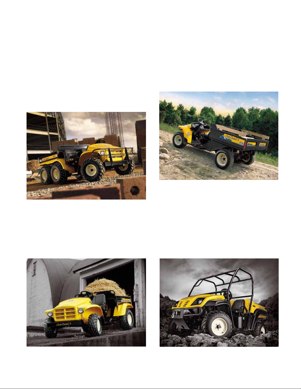
1. INTRODUCTION: PRODUCT LINE
6X4
Cub Cadet entered the utility vehicle market in the
2003 season with a 6X4 vehicle having fully independent suspension and Honda power (20 H.P.). The Big
Country 6X4 continues in production with evolutionary
changes and a switch to Kohler power. See Figure 1.1.
Big Country 6X4
Figure 1.1
Steel-bed 4X2
In 2004, a 4X2 vehicle was introduced. The 4X2
shares the 6X4 front suspension, has an 18 H.P.
Honda engine and a push-button controlled transmission. Evolutionary changes include a switch to Kohler
power. See Figure 1.2.
Poly bed 4X2
For 2005, a lighter-duty version of the 4X2 was introduced, using a plastic cargo box and a 9.5 H.P. drives
system sourced from Kawasaki. See Figure 1.3.
4X2 “Poly Bed”
Figure 1.3
All of these first-generation utility vehicles share a common structure from the cargo box forward. The 6X4
carries a fully enclosed rear structure with swing-arm
suspension. The 4X2s carry the engine and transaxles
on a pivoting cradle that acts as the rear suspension.
4X4
The 4X4 vehicle that is the subject of this handbook
represents a complete departure from the first generation vehicles. See Figure 1.4.
4X2 Steel Bed
Figure 1.2
New 4X4
Figure 1.4
1
Page 6

Chapter 1: Introduction
2. UNDERSTANDING UTILITY VEHICLE MODEL NUMBERS
e.g.: 37AJ467D710
• 37 - - - - - - - - - indicates that this is a U.V.
• - - A - - - - - - - - indicates the engineering level
• - - - J - - - - - - - indicates the engine type
• - - - - 4 - - - - - - indicates the number of wheels
• - - - - - 67 - - - - indicates the series and trim
• - - - - - - - D - - - indicates the type of tires
• - - - - - - - - 710 indicates that it is Cub Cadet
2.1. Engine type detail:
• B = Kohler Command 18 H.P. V-twin
• C = Kohler Command 20 H.P. V-twin
• J = Caterpillar Diesel 20 H.P. liquid cooled
• N = Kawasaki 9.5 H.P. single, inclined
• R = Honda 18 H.P. V-twin
• S = Honda 20 H.P. V-twin
3. PROFESSIONAL SHOP MANUAL INTENT
This Manual is intended to provide service dealers with
an introduction to the mechanical aspects of the new
vehicle.
This Professional Shop Manual covers the second
generation Cub Cadet Utility Vehicles more specifically,
and in greater depth than the origanal Shop Handbook.
• The content in this manual supersedes any content in the handbook.
• Detailed service information about the engine
will be provided by the engine manufacturer, in
most cases.
Disclaimer: This manual was written using second
generation vehicle. The information contained in this
handbook is correct at the time of writing. Both the
product and the information about the product are subject to change without notice.
About the text format:
NOTE: is used to point-out information that is
relevant to the procedure, but does not fit as a
step in the procedure.
2.2. Series detail:
• 1 = poly-bed 4 x 2
• 3 = steel bed 4 x 2
•4 = 6 x 4
•6 = 4 x 4
2.3. Trim detail:
• 0 = yellow on 6 x 4 and 4 x 2
• 1 = camouflage on 6 x 4 and 4 x 2
• 2 = fire rescue red on 6 x 4 and 4 x 2
• 6 = yellow on 4 x 4
• 7 = camouflage on 4 x 4
2.4. Tires
• A = turf tires
• B = knobby tires
• C = heavy-duty tires
• D = trail tires
• E = Fire Rescue: f. run-flat tires, r. trail tires
CAUTION: is used to point-out potential danger
to the technician, operator, bystanders, or surrounding property.
• Bullet points: indicate sub-steps or points.
Disclaimer: This Professional Shop Manual is
intended for use by trained, professional technicians.
• Common sense in operation and safety is
assumed.
• In no event shall MTD or Cub Cadet be liable for
poor text interpretation, or poor execution of the
procedures described in the text.
• If the person using this manual is uncomfort able
with any procedures they encounter , they shou ld
seek the help of a qualified technician or Cub
Cadet Technical Support.
• G = poly-bed trail tires
2
Page 7
Chapter 1: Introduction
Fasteners:
• Most of the fasteners used on the vehicle are
sized in fractional inches. Some are metric.
For this reason, wrench sizes are frequently
identified in the text, and measurements are
given in U.S. and metric scales.
• If a fastener has a locking feature that has
worn, replace the fastener or apply a small
amount of releasable thread locking compound
such as Loctite® 242 (blue).
• Some fasteners like cotter pins are single-use
items that are not to be reused.
Other fasteners such as lock washers, retaining
rings, and internal cotter pins (hairpin clips) may
be reused if the do not show signs of wear or
damage. This manual leaves that decision to
the judgement of the technician.
Assembly:
Torque specifications may be noted in the part of the
text that covers assembly, they may also be summarized in tables along with special instructions regarding
locking or lubrication.
Whichever method is more appropriate will be used. In
many cases, both will be used so that the manual is
handy as a quick-reference guide as well as a step-bystep procedure guide that does not require the user to
hunt for information.
4. LIFTING AND SUPPORTING
CAUTION: Use common sense and safety when
lifting and supporting any equipment:
• Always work on a firm, level surface that will
support the load to be placed on it.
• Never leave equipment supported by hydraulic
means: hydraulic jacks are for lifting. Once
lifted, the equipment should be positioned on
and supported by jack stands of sufficient capacity to ensure safety.
• Confirm that the equipment is firmly seated on
the jack stands before doing any work that
results in exposure to falling or crushing hazard.
• Use caution when positioning jacks and jack
stands, so as not to damage any fuel lines,
brake lines, electrical conduits, or linkages.
• Do not lift or support the vehicle by the cradle
that the engine and transfer case are mounted
to. It is vibration-isolated from the rest of the
vehicle. The rubber isolator mounts are not
designed to support the weight of the vehicle.
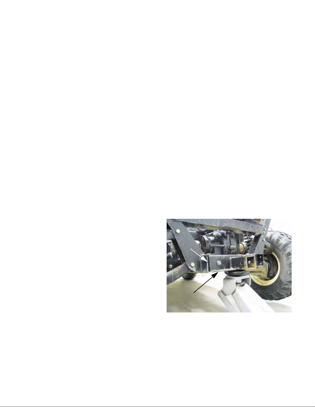
The utility vehicle may be lifted from the rear by placing
a jack under the rear-most cross-member. This crossmember also provides a mounting point for the 2” class
1 hitch receiver. See Figure 1.5.
The level of assembly instructions provided will be
determined by the complexity and of reassembly, and
by the potential for unsafe conditions to arise from mistakes made in assembl y.
Some instructions may refer to other parts of the manual for subsidiary procedures. This avoids repeating
the same procedure two or three times in the manual.
Rear cross-member
Accessory
receiver
Figure 1.5
3
Page 8
Chapter 1: Introduction
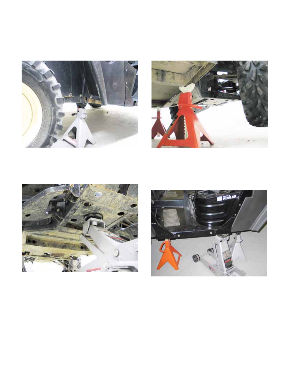
Jack stands can safely be positioned beneath the upright frame members that are roughly even with the
centerline of the tray that supports the engine and
transfer case. See Figure 1.6.
Figure 1.6
The front of the vehicle may be safely lifted by placing a
jack directly under the mounting point where the front
differential joins the frame. See Figure 1.7.
Jack stands will safely support the front of the vehicle if
positioned beneath the frame, where the front out-rigger extends to meet the base of the OPS.
See Figure 1.8.
Figure 1.8
Alternatively, the vehicle may be lifted by positioning a
jack along the outer frame channel, where the rear
out-rigger extends to meet the base of the OPS .
See Figure 1.9.
Figure 1.7
Figure 1.9
NOTE: The center of gravity for the vehicle is
beneath the seat support structure.
NOTE: The outer frame channel will support the
vehicle without damage.
4
Page 9
Chapter 1: Introduction
5. DRIVE SYSTEM DESCRIPTION
• A belt-type CVT (Continuously Variable Transmission) system carries power from the engine
crankshaft to the transfer case.
See Figure 1.10.
CVT driven
element
CVT belt
CVT driving element
Figure 1.10
• The CVT range provides strong torque and
acceleration, limiting speed to 25 MPH (40
KPH).
• The driving clutch on the engine crankshaft uses
centrifugal force to operate a mechanism that
pulls the sheaves closer together.
The faster the engine spins, the closer the
sheaves get.
As the sheaves close-down on the belt, the belt
is forced outward.
As the belt is forced outward, the drive ratio
decreases so that fewer crankshaft revolutions
equate to more input shaft revolutions at the
input shaft of the transfer case.
•The transfer case is mounted adjacent to the
engine, with the input shaft running fore-and-aft
in the frame. See Figure 1.11.
Transfer
case
Figure 1.11
• The transfer case contains two forwar d ratios,
neutral, and reveres.
• Gear selection is controlled by rods and a selector lever sourced from Hurst®.
Drive shafts with Hooke/Spicer type universal joints
extend fore and aft from the output shafts of the transfer case to drive the front and rear differentials.
The rear differential has a cast iron housing and a
cable-actuated locking feature. See Figure 1.12.
Differential lock
actuator
Rear differential
NOTE: A lower numeric ratio results is frequently referred to as a “steeper” or “taller” d rive
ratio, yielding in increased top speed.
• As the effective diameter of the driving pulley
increases, the belt has less available length to
reach the driven pulley.
The sheaves of the driven pulley is springloaded so that it can absorb the additional tension.
An additional effect is that the belt is drawn
deeper into the sheaves, reducing the effective
diameter of the driven pulley.
Reducing the diameter of the driven pulley further reduces the drive ratio.
Figure 1.12
5
Page 10
Chapter 1: Introduction
The front differential has an aluminum housing, and
an electronically controlled, slip sensing Auto-Lok®
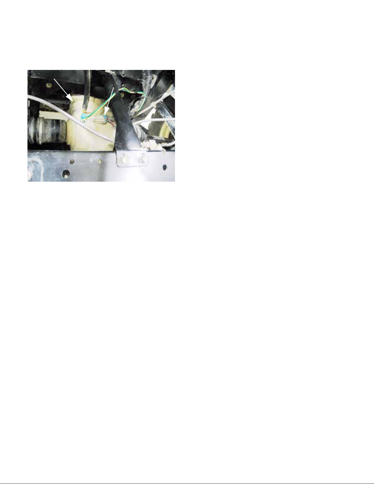
feature. See Figure 1.13.
Front differential
• The front differential is engaged or disengaged
using a rocker switch on the dashboard.
Each differential transfers power to the drive hubs
through a drive shaft with Rzeppa-type constant velocity joints at each end.
Electrical connection for
Auto-Lok® feature
Figure 1.13
6. SERVICE INTENT
The transfer case is manufactured by Cub Cadet. If it
fails during the first year, it should be removed and
replaced as a complete unit.
• In the event of a failure, the transfer case will be
called back for engineering analysis.
• If the failure is warrantable, Cub Cadet will cover
the cost of replacement.
• If the failure is not warrantable, replacement will
be at the customer’s expense.
• Beyond the first year, but within the first two
years, the decision whether to repair or replace
the transfer case will be based on economic feasibility and the availability of parts and assemblies.
• Beyond the warranty period, the dealer can
repair or replace the transfer case at their own
discretion.
The remainder of the drive system (CVT, drive shafts,
axles, differentials) is purchased from outside vendors.
• If any of these items fail in the first two years,
they should be removed and replaced with a
complete unit. The only exception to this may be
the axles. Rzeppa (Constant Velocity) joints
may be available to repair rather than replace
axles. Service intent has not been decided as
this manual goes to print.
• In the event of a failure, the component will be
called back for engineering analysis and vendor
recovery.
• If the failure is warrantable, Cub Cadet will cover
the cost of replacement.
• If the failure is not warrantable, replacement will
be at the customer’s expense.
• Beyond the warranty period, internal parts for
the differentials will be made available so that
the dealer can repair or replace them at their
own discretion.
Kohler Engines will be serviced as they are in the rest
of the Cub Cadet product Line. They are seen as an
integral part of the Cub cadet product, with parts and
warranty coverage provided through Cu b Cad e t.
Caterpillar Engines in Cub cadet equipment will continue to be serviced exclusively by CAT dealers.
6
Page 11
Chapter 1: Introduction
7. SPECIAL TOOLS
NOTE: There are many specialized tools that
will make servicing the Cub Cadet 4X4 easier.
There are only a couple of tools that are not
likely to be in a technician’s normal tool assortment that necessary to service the 4X4.
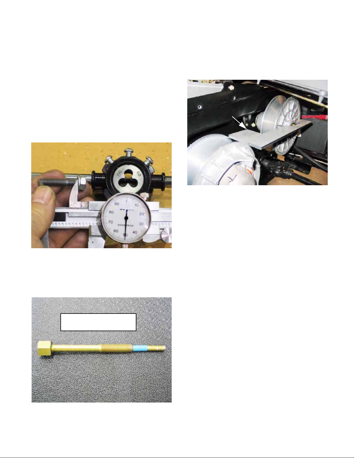
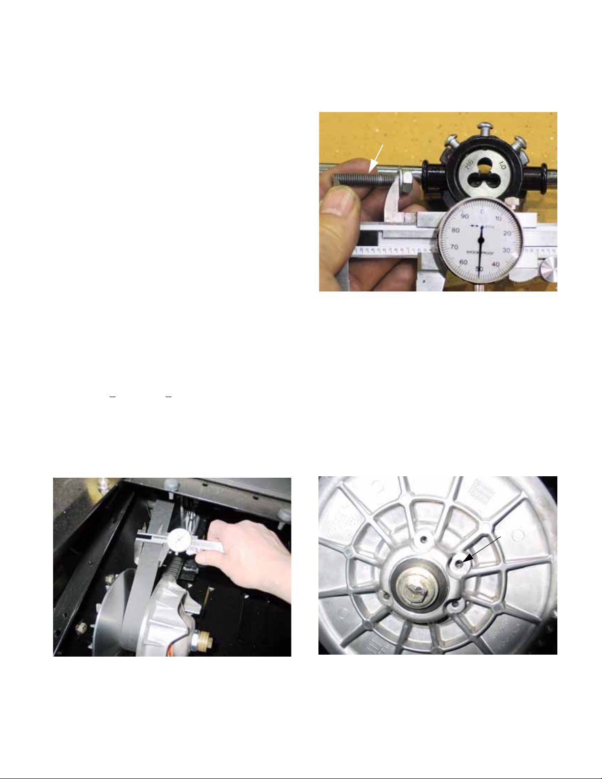
7.1. A small metric screw (6m/1.0) (size/thread pitch)
having a minimum thread length of 1.15” (2.9cm)
can be used to spread the sheaves of the driven
clutch. This is necessary if the belt is to be
replaced without removing both pulleys. The
screw can be purchased locally and modified
using a thread die. See Figure 1.14.
7.3. A pulley alignment tool should be used to check
the alignment of the drive pulley and driven pulley after any procedure that may have disturbed
the alignment, or if unusual belt wear occurs.
See Figure 1.16.
Alignment tool
P/N: 707-04878
Figure 1.16
Figure 1.14
7.2. The second tool that is necessary to service the
drive system is a puller that draws the driving
clutch off of the engine crankshaft.
See Figure 1.15.
Driving pulley removal tool:
Part number: 759-04111
Figure 1.15
7
Page 12

Chapter 1: Introduction
8
Page 13
Chapter 2- Drive System: CVT and Transfer Case
CHAPTER 2- DRIVE SYSTEM: CVT AND TRANSFER CASE
DRIVE SYSTEM: SERVICE INTENT
1. The transfer case is manufactured by Cub
Cadet. If it fails during the first two years, it
should be removed and replaced as a complete
unit.
• In the event of a failure, the transfer case will be
called back for engineering analysis.
• If the failure is warrantable, Cub Cadet will cover
the cost of replacement.
• If the failure is not warrantable, replacement will
be at the customer’s expense.
• Beyond the warranty period, internal parts will be
made available so that the dealer can repair or
replace the transfer case at their own discretion.
2. The remainder of the drive system (CVT, drive
shafts, axles, differentials) is purchased from
outside vendors.
• If any of these items fail in the first two years,
they should be removed and replaced with a
complete unit.
• In the event of a failure, the component will be
called back for engineering analysis and vendor
recovery.
CVT AND TRANSFER CASE OPERATION
1. The transfer case contains a relatively conventional three-shaft gear-set providing Neutral,
Reverse, Forward, and Forward Low-range.
2. The variation in drive speed within each gear is
created by a combination of engine RPM and a
CVT belt drive system.
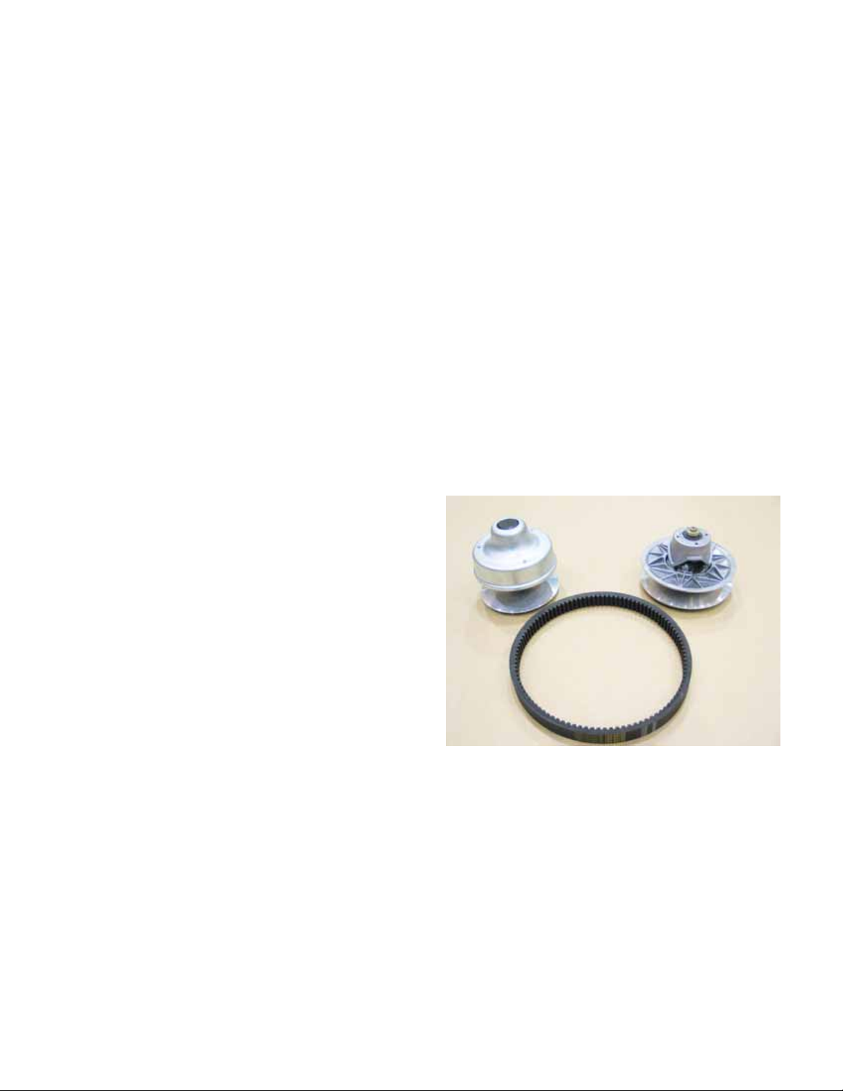
3. The CVT belt drive system consists of :
See Figure 2.1.
• Driving element = driving pulley = centrifugal
torque converter mounted to the crankshaft.
• Driven element = driven pulley = pulley sheaves
mounted to the input shaft of the transfer case
that react to the motion of the driving element.
• A special belt that transfers power from the driv-
ing element to the driven element.
Driving element Driven element
• If the failure is warrantable, Cub Cadet will cover
the cost of replacement.
• If the failure is not warrantable, replacement will
be at the customer’s expense.
• Drive system components other than the CVT
and transfer case are covered in gr eater depth in
the Drive shafts, Axles, and Differentials chapter
of this manual.
Belt
Figure 2.1
4. Common parts:
4a. The belt and driven element are the
same on both models of the current Cub
Cadet 4X4.
4b. The driving elements are different for
gas and diesel versions. The gas engine
and diesel engines have different torque
curves and maximum operating speeds.
9
Page 14
Chapter 2- Drive System: CVT and Transfer Case
4c. The driving elements are tuned to get the
best vehicle performance out of each
model engine, taking into account: engine
power band and top speed, vehicle
weight, maximized vehicle pulling power,
maximized vehicle acceleration, and a 25
MPH (40 KPH) maximum speed.
5. Operation:
5a. At rest (engine OFF or at low idle) the
sheaves of the driving element (on the
engine crankshaft) are at the widest point
of their travel. The belt rests on a central
bearing surface, but no significant power
is transmitted to the driven element at idle
speed. See Figure 2.2.
Low idle speed
Driving element released
(spread)
5b. At about 1,400 RPM, the sheaves move
closer to each-other. As they do, they
touch the sides of the belt and begin to
transmit power. See Figure 2.3.
Low RPM:
Driving element
beginning to engage belt
Belt deep in sheave
Figure 2.3
• The sheaves are moved by fly-weights within the
driving element housing. Centrifugal force
drives the fly-weights out. The fly-weights are
levered against the sheave, forcing it inward.
Figure 2.2
5c. As the engine RPMs increase, the
sheaves close further, forcing the belt outward on the sheaves. See Figure 2.4.
Moderate engine speed
Driving pulley partially closed-down
Belt partially shifted-out
Figure 2.4
10
Page 15
Chapter 2- Drive System: CVT and Transfer Case
• The further the drive point (contact patch
between the belt and the sheaves) is from the
crankshaft, the greater the effective circumference of the driving pulley (element).
• The greater the effective circumference of the
driving pulley, the more linear motion is transferred to the belt for each crankshaft revoluti on.
• This increases the drive speed, but reduces the
amount of torque the engine transfers to the
drive system.
• If the engine is over-loaded by a combination of
grade and cargo weight while operating at full
throttle, the RPMs will be pulled-down. As the
engine RPMs are reduced, the drive ratio will
automatically shift in the numerically higher
direction, increasing the amount of torque available to the wheels, at the expense of ground
speed.
5d. As the belt is forced outward on the
sheaves of the driving element, the driven
element spread allowing the belt to be
drawn deeper-in. See Figure 2.5.
Driven pulley at speed
Sheaves
Belt deep in sheaves
5f. At about 3,000 RPM (Kohler) or 2,500
RPM (Caterpillar) the driving element
reaches the end of its travel.
See Figure 2.6.
Driven element fully
drawn together:
Belt at outer
edge
Figure 2.6
• Any increase in vehicle speed beyond the end o f
CVT travel is due only to an increase in engine
speed. The rate of vehicle acceleration will
level-off.
IDLE SPEED AND TOP NO-LOAD SPEED
Belt
Figure 2.5
5e. As the belt is drawn deeper into the driven
pulley, two things are accomplished:
• Belt tension is held constant, even though the
effective size of the driving pulley changes.
• The range of available drive ratios is widened.
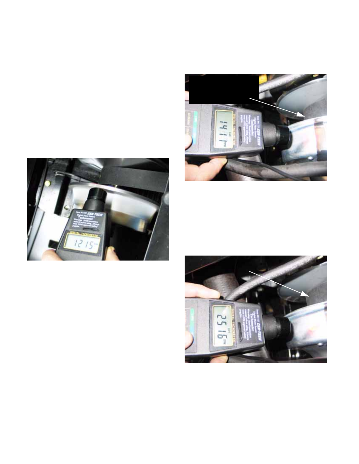
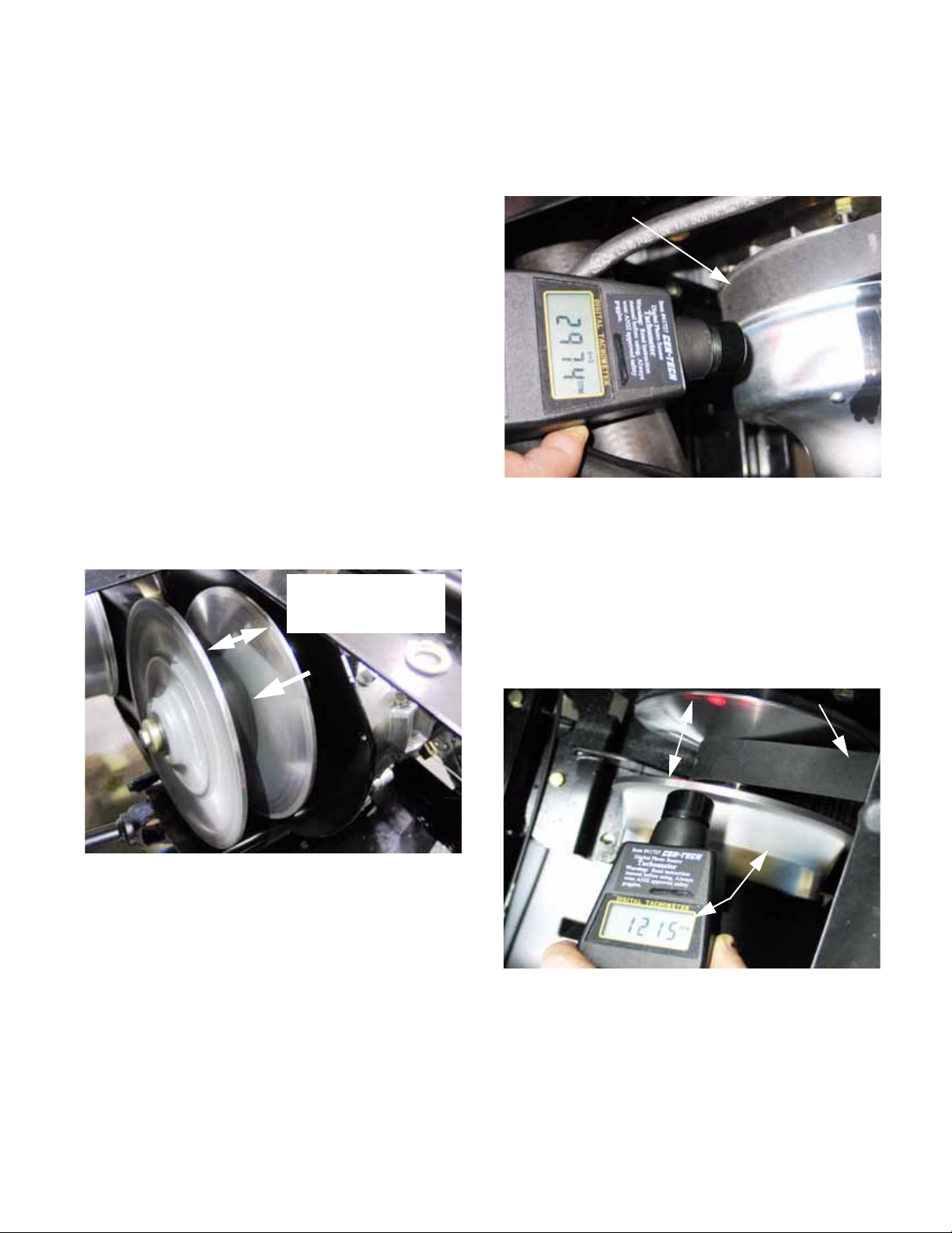
1. The Kohler and CAT engines should idle at
1,200 RPM. See Figure 2.7.
Belt still
Sheaves
spread
Clutch spinning
at idle speed
Figure 2.7
11
Page 16
Chapter 2- Drive System: CVT and Transfer Case
• Slower idle speeds will result in poor idle quality,
reduced flow of cooling air, and reduced oil flow.
• Higher idle speeds will result in harsh gear
selector action and possible internal damage to
the transfer case.
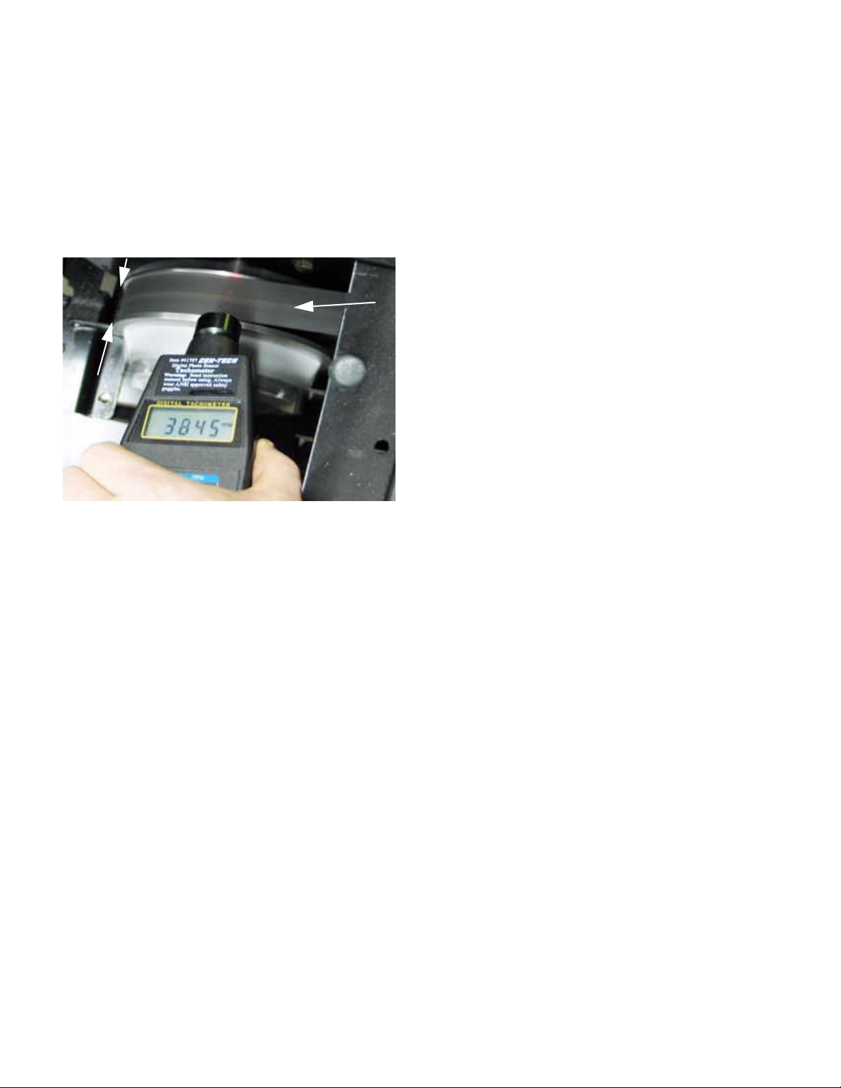
2. Top no-load speed should be 3 ,600 RPM fo r th e
Caterpillar and 3,850 RPM for the Kohler:
See Figure 2.8.
Sheaves
closed
Engine at
max. RPM
Figure 2.8
• Slower top no-load speeds will result in diminished performance.
• Higher top no-load speeds will result in unsafe
operating conditions and possible over-speed
engine failure.
3. If the idle speed and top-no-load speed do not
fall into this range, refer to the appropriate
engine chapter for adjustment procedures
• Caterpillar related systems Chapter 8
• Kohler engine service access and fuel system
Chapter 7
Belt spinning
DRIVE SYSTEM SERVICE ACCESS, SAFETY, AND
TIPS
1. When working on the belt, block the wheels to
prevent the UV from rolling.
2. Place the transmission in neutral.
3. When working on any components (like the
CVT) that rotate with the engine, disable the
engine:
3a. Disconnect and ground the spark plug
wires on a gasoline engine.
3b. Unplug the fuel shut-off solenoid on a die-
sel engine.
3c. Remove the key from the key switch.
3d. Preferably, disconnect the ground cable
from the negative terminal of the battery.
4. Unless a procedure specifically requires the
engine to be running, the engine should be
turned-off for all maintenance, adjustments, and
repair.
5. To reach the CVT, fold the seats forward and
secure them with shock cords. Release the
Camloc® fasteners and lift the parcel bin out
from beneath the driver’s seat
6. Once accessed, the driving element, the driven
element, and the belt can be removed. There
are some simple but specialized tools r equir ed
to loosen the belt and remove the driving element
•A small screw can be used to spread the
sheaves of the driven element so that the belt
can be removed. Specific dimensions are given
in the belt removal section of this chapter.
•A clutch puller is needed to pull the driving ele-
ment off of the tapered crankshaft.
NOTE: The belt may be remove d independently,
or the CVT may be removed complete with the
belt.
12
Page 17
Chapter 2- Drive System: CVT and Transfer Case
DRIVE SYSTEM ADJUSTMENTS:
1. CVT spacing and alignment:
• Sp acing and alignment are critical to pr oper CVT
performance and belt longevity.
• In normal service, these items should not be an
issue on this vehicle. The engine and transfer
case are firmly tied to each-other by the engine /
transmission plate that holds proper spacing and
alignment.
2. Adjustment of the driving element and driven
element:
• The CVT is tuned to maximize performance of
the vehicle. It should require no adjustment in its
normal service life.
• While it is mechanically possible to disassemble
the driving and driven elements, individual parts
will not be available through Cub Cadet.
CVT SERVICE
1. BELT REMOVAL
NOTE: The procedure to remove the belt is the
same for the Kohler and the Caterpillar engines.
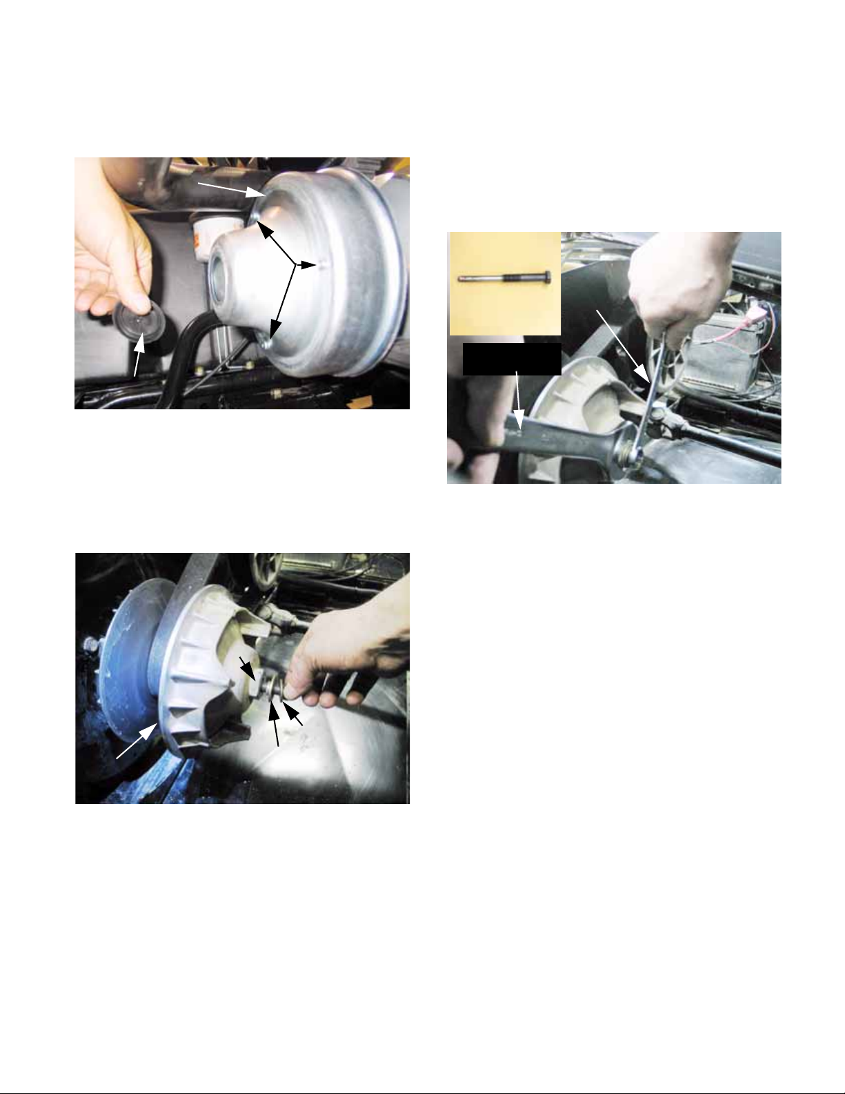
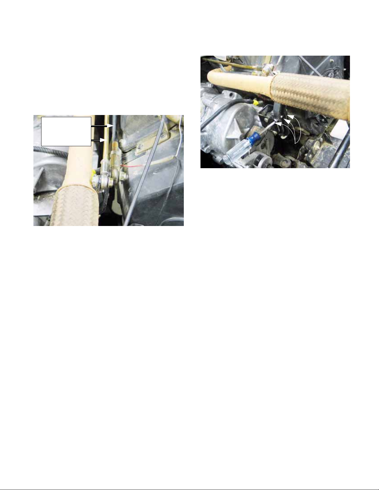
1a. When new, the belt measures 1.335”
+
.031” (33.9 + .8mm) across the wide flat
outside surface of the belt. The belt is
considered worn when the measurement
is 1.20” (30.5mm) or less. some degradation of performance may begin to occur as
belt is worn to less than 1.275” (32.4mm).
See Figure 2.9.
1b. To remove the belt, a 6mm/1.0 screw with a
minimum thread length of 1.15" (2.9cm)
will be required. See Figure 2.10.
1.15” (2.9cm)
thread length
Figure 2.10
NOTE: A 6mm screw with a thread pitch of 1.0
may be purchased locally. The minimum thread
length needed is longer than the threads of a
standard screw of this size. It will be necessary
to cut threads further up the shank of the screw
using a thread-cutting die.
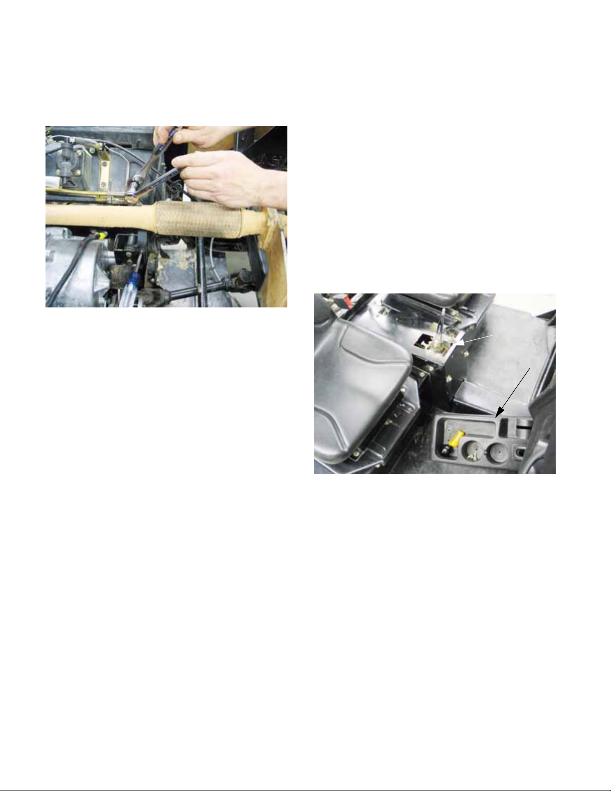
1c. There are 4 holes in the face of the driven
element. Three of them are close
together, one is 180 degrees away from
the others. The middle hole of the set of
three is threaded.
See Figure 2.11.
New: 1.335”
(33.9mm)
Worn: 1.20”
(30.5mm)
Figure 2.9
Tapped hole
Figure 2.11
13
Page 18
Chapter 2- Drive System: CVT and Transfer Case
1d. Thread the screw into the tapped h ole in the
outer half of the driven element sheave.
The end of the screw will press against
the inner half of the sheave, spreading the
two apart. See Figure 2.12.
Screw maintains
distance between
sheaves
Figure 2.12
NOTE: It is common practice among snowmobil-
ers to carry a spare belt. Belt life on this vehicle
should not be an issue, but if the utility vehicle is
operated in very remote areas, it may provide
some peace-of-mind for the operator. If they
choose to carry a spare belt, a suitable screw
and a 10mm wrench should be kept with it.
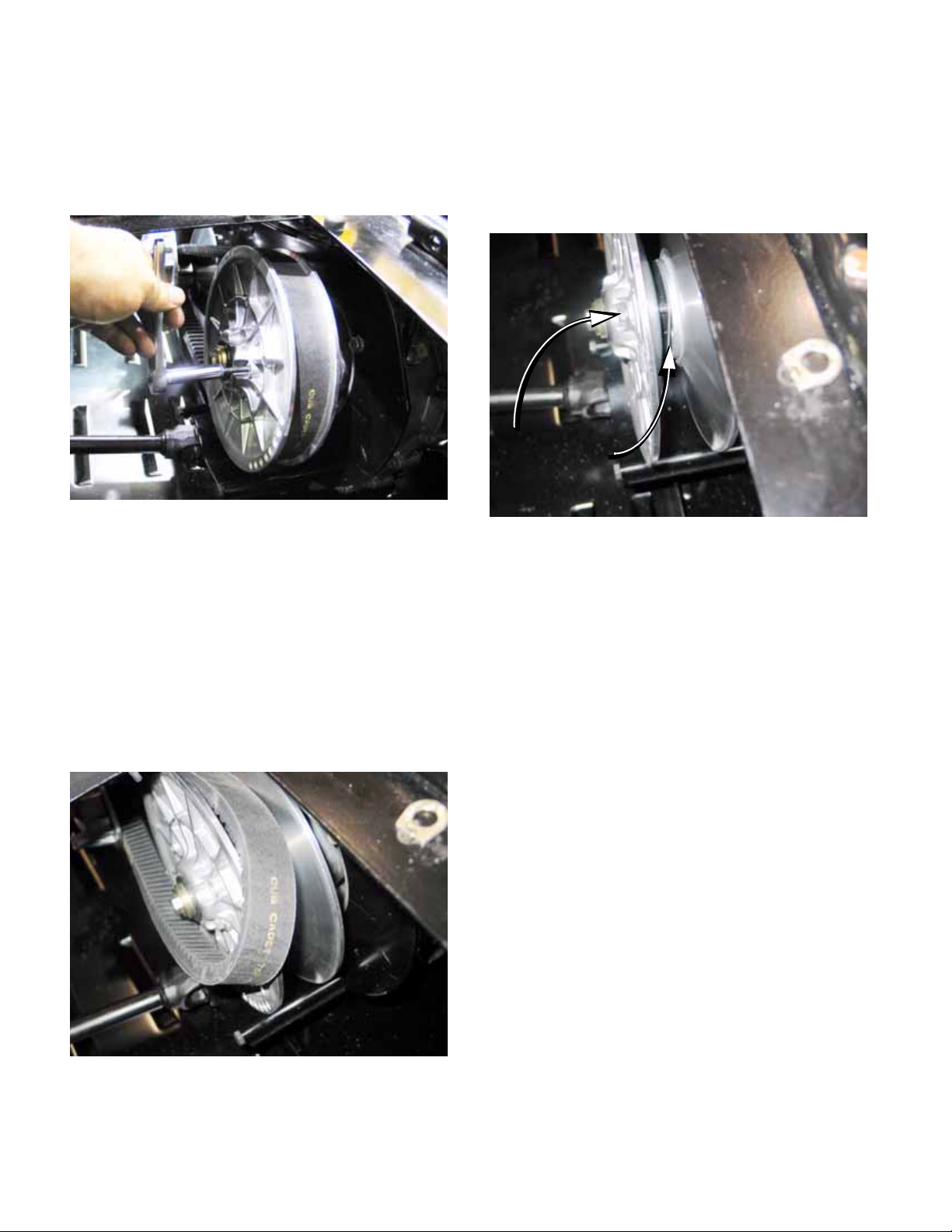
1e. As the sheaves are spread, the tension on
the belt will be relieved, and the belt can
be rolled-off of the driven element (pulley).
See Figure 2.13.
2. Removal of the Driving element
NOTE: On the Caterpillar engines, The belt may
be harder to roll off the sheave, but it will roll off.
1f. The belt can easily be installed by revers-
ing the removal process. See Figure 2.14.
Figure 2.14
NOTE: When the belt is installed, remove the
screw before operating the vehicle
NOTE: It may be necessary to start the vehicle, ,
and rev the engine in neutral to seat the belt.
NOTE: The driving element is most easily
removed after the belt is taken- off.
NOTE: The driving element can be removed
with the belt in place, but installation may require
the driven element sheaves to be spread unless
all three parts of the CVT are installed together,
as described later in this section.
Figure 2.13
NOTE: The bolt that holds the driving element to
the crankshaft can be reached by removing the
plastic cap from the end of the driving element.
If the driving element spins the crankshaft when
the tool is tightened it will be necessary to hold
the CVT or lock the crankshaft. One means of
holding the CVT involves removing the cover.
That is the technique described in this section.
2a. Disconnect and ground the spark plug
leads (Kohler) or un-plug the fuel shut-off
solenoid (Caterpillar).
14
Page 19
Chapter 2- Drive System: CVT and Transfer Case
2b. Remove the three screws holding the
cover in place, then remove the co v e r.
See Figure 2.15.
Driving element cover
Screws
Plastic cap
Figure 2.15
2c. Hold the large nut with a 30mm wrench
while loosening the crankshaft bolt with a
5/8” wrench.
2d. Withdraw the bolt, washers, and shoulder
spacer. See Figure 2.16.
3. Install the clutch removal tool (M14 - 2.O) by
threading it into the clutch, pressing against the
crankshaft.
3a. Hold the pulley with a 30mm wrench, and
turn the tool using a 22mm wrench. This
will force the driving element off of the
crankshaft. See Figure 2.17.
Inset:
clutch tool
One wrench
to turn the
tool
One wrench to
hold the clutch
Figure 2.17
CAUTION: There is a tapered fit between the
driving element and the crankshaft. Applying
force to the perimeter of the driving element will
break it.
Driving
element
Nut
Shoulder washer
Figure 2.16
Flat washer(s)
3b. If the belt was not previously removed, it
can be taken-off as the driving element is
removed.
4. Removal of the driven element
4a. Remove the belt.
NOTE: The driving element fits on a tapered
shaft. It can be removed with the belt in-place
because the tapered shaft provides freedom of
movement as soon as the driving element
comes loose.
The driven element fits on a splined shaft. As the
driven element is drawn off the shaft, the belt will
tighten, making removal difficult even with the
sheaves spread. The belt should be removed
before taking-off the driven element.
15
Page 20
Chapter 2- Drive System: CVT and Transfer Case
4b. Place the transfer case in H position, and
set the parking brake.
4c. Loosen the bolt that holds the driven ele-
ment to the input shaft using a 9/16”
wrench.
NOTE: Hold the driven element from rotating
using a pin spanner, if needed.
4d. Remove the bolt and washers.
See Figure 2.18.
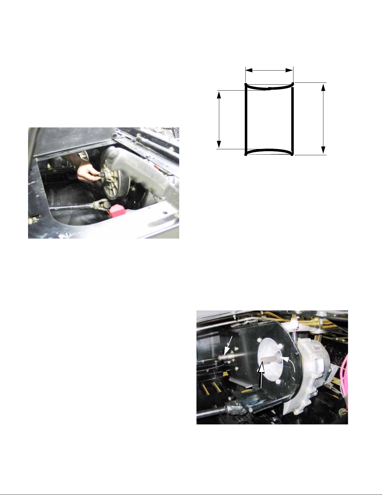
6. Make the wood block spacer as described in the
accompanying illustration. See Figure 2.19.
3-1/2” (8.9CM)
4-3/8”
(8.6CM)
NOTE: BLOCK ENDS MAY BE
V-SHAPED OR CURVED
Figure 2.19
6a. Prepare the CVT for installation:
See Figure 2.20.
• Clean the shafts and the surrounding area
before installing the CVT.
5-1/8”
(13.1CM)
Figure 2.18
4e. At this point, the driven element may be
slipped off of the transfer case input sha ft.
5. CVT Installation
NOTE: The driving element and driven element
can be installed individually, then the belt can be
rolled-on as described in the belt removal section of this chapter.
Alternatively, both elements and the belt can be
installed all-at-once using a simple wood-block
tool. This method is described in the following
steps.
Preparation and torque specs remain the same
for both methods.
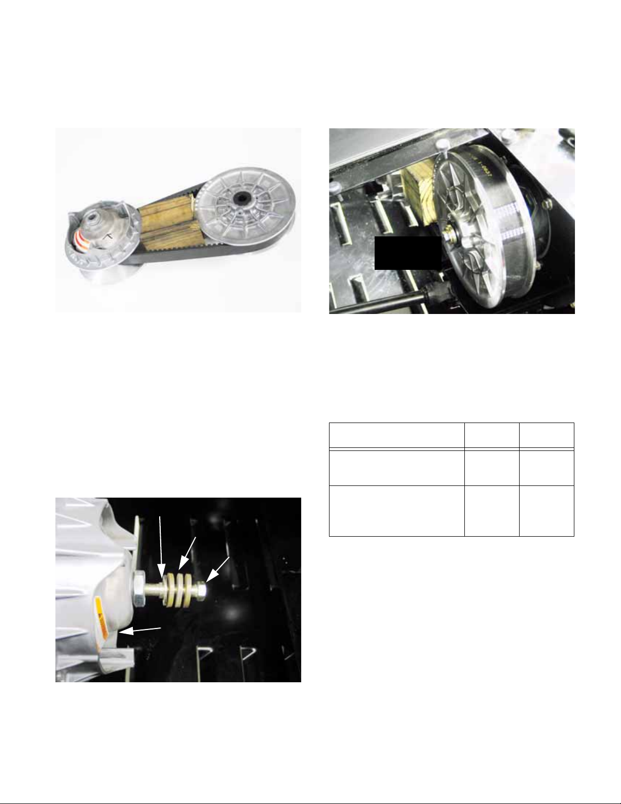
• Confirm the presence of the .060” (1.5mm)
spacer on the shaft between the driven element
and the transfer case housing.
• A small amount of anti-seize compound may be
used on the splined joint between the input shaft
of the transfer case and the driven element.
• The tapered joint between the driving element
and the crankshaft must be clean and dry.
Tapered shaft
Spacer
Splined shaft
16
Figure 2.20
Page 21
Chapter 2- Drive System: CVT and Transfer Case
6b. Install the belt around the pulleys and insert
the wood block tool between the pulleys
to establish correct spacing.
See Figure 2.21.
Wooden tool sets
spacing and holds
assembly together
for installation
Figure 2.21
6c. Install the belt and pulleys, with the wood
block between them, onto the crankshaft
of the engine and the input shaft of the
transfer case.
6d. Apply a small amount of thread locking
compound such as Loctite® 262 (red) to
the bolts that secure each pulley.
6e. Secure the driving element to the crank-
shaft using the bolt, washers, and shoulder spacer previously removed. Do not
tighten fully at this time. See Figure 2.22.
Shoulder spacer
Washers
6f. Secure the driven element to the input shaft
using the bolt, washer, and shoulder
spacer previously removed. Do not
tighten fully at this time. See Figure 2.23.
CVT installed
all at once
Figure 2.23
6g. Tighten the bolts securing the pulleys to
their respective shafts in even steps,
drawing the pulleys into place.
6h. Once seated, tighten the bolts to the spec-
ified torque:
Item ft-lbs N-m
Driving element to
32-36** 43-49**
engine crankshaft
Driven element to
70-80** 95transfer case input
shaft
109**
Bolt
Driving element
Figure 2.22
** Install with permanent thread locking compound
such as Loctite®
17
262 (red).
Page 22
Chapter 2- Drive System: CVT and Transfer Case
6i. Remove the wood block tool.
See Figure 2.24.
Tighten bolts
and remove
block
Figure 2.24
6j. Test the operation of the drive system in a
safe area, then allow the exhaust system
to cool before final assembly.
6k. Final assembly: install the cover and plug
on the driving element and replace the
parcel bin under the passenger’s seat.
DRIVE SYSTEM ADJUSTMENTS:
TRANSFER CASE SHIFT LINKAGE
1. Before attempting any linkage repair of adjustment, confirm whether the problem at hand is in
the linkage or elsewhere in the system.
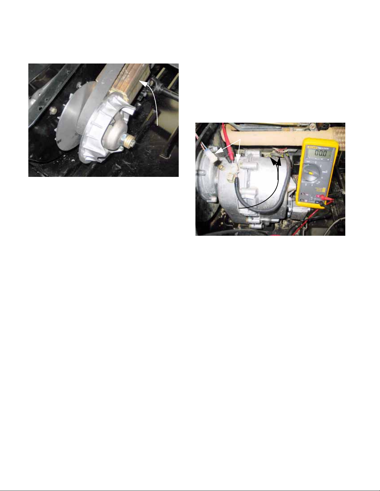
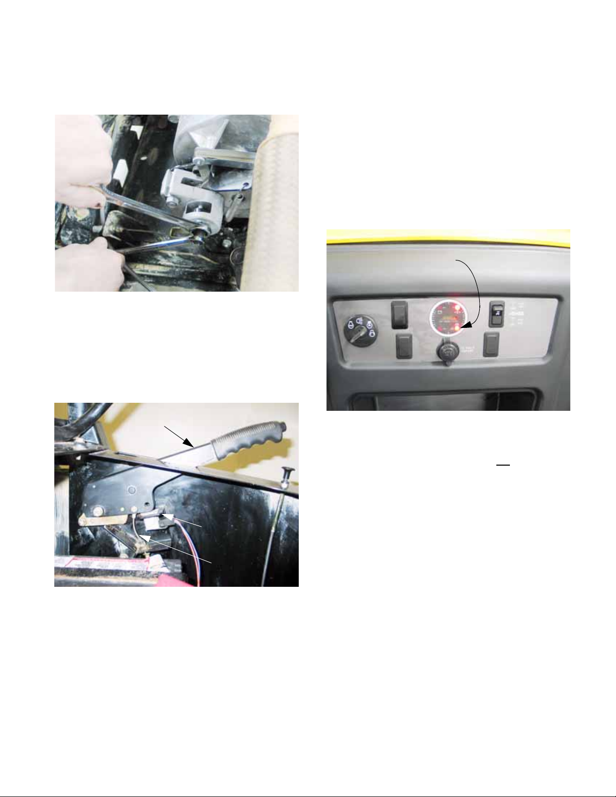
2. A handy quick-check to confirm that the transfer
case is in neutral when the gear selector is in
neutral can be made using the two safety
switches in the starter circuit: See Figure 2.25.
Switch harness unplugged
Both switches
in series:
contacts closed
Figure 2.25
2a. Locate and disconnect the harness that
leads to the neutral safety switches.
2b. Connect a DVOM or continuity light to the
pair of terminals on the disconnected harness.
2c. When the transfer case is in neutral, there
should be continuity (0.0 Ω) between the
two wires in the terminal.
NOTE: There are two sets of shift forks within
the transfer case. Each shift fork has a safety
switch associated with it. When both shift forks
are in the neutral position, the contacts of both
switches will be closed. The switches are connected in series, so the closure of both switches
completes the circuit.
3. The correct operation of the switch can be confirmed by rotating the transfer case input shaft
and observing the reaction of the output shafts.
4. After correct internal operation of the transfer
case is confirmed, check the linkage. Correct
any internal problems before proceeding. If the
transfer case has internal damage, no amount of
external adjustment will fix it.
18
Page 23
Chapter 2- Drive System: CVT and Transfer Case
NOTE: Methodology: start at the source (the
transfer case), and work toward the control input
(the gear selector).
5. Operate the gear selector through its full range
of motion (high range forward, low range forward, neutral, and reverse). Look for the following issues: See Figure 2.26.
Forward-Neutral Reverse rod
Low-range rod
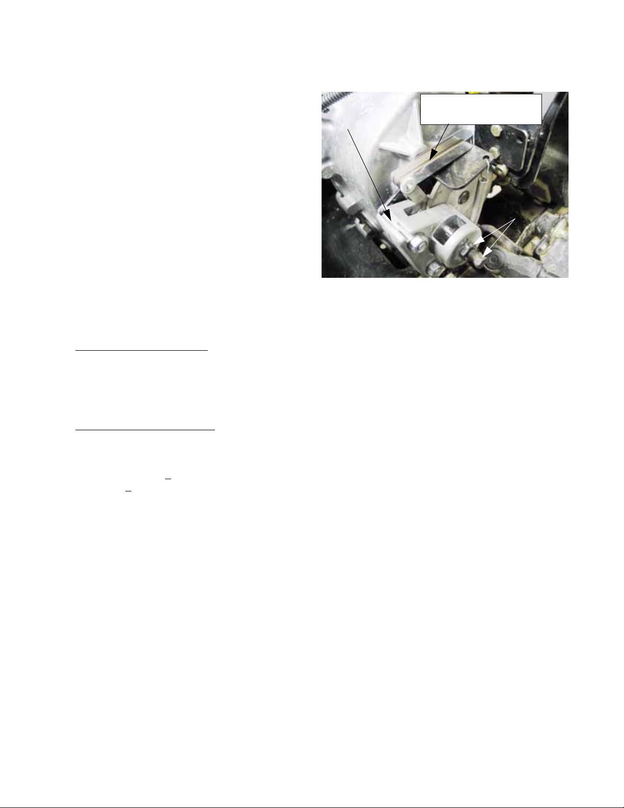
7. Centering the linkage: See Figure 2.27.
Neutral
alignment
holes
Figure 2.27
7a. With the linkage disconnected, the shift
forks are centered in the neutral position
by detent springs.
Figure 2.26
• Lost motion
• Loose hardware
• Mechanical interference
• Unintended bends in the linkage
• Excessive linkage bowing under load
• Engagement of the gear that is selected
6. Correct any of these initial problems before proceding with adjustment.
NOTE: It is possible to make a damaged linkage
work better by compensating for the damage
with adjustment. This should not be considered
complete repair.
7b. At this point the shift arms can be locked
into the neutral position by inserting a 3/
16” (or 5mm) dowel rod through the alignment holes in the shift lever bracket and
shift arms located on the back of the
transfer case housing.
7c. The center-point of neutral position at the
Hurst gear selector lever corresponds
with the center of the range where the
shift lever can move from the high-neutralreverse gait into the neutral-low gait.
7d. Find the point were the Hurst lever moves
left and right between the two gates. This
is the center-point of it’s range of travel.
19
Page 24
Chapter 2- Drive System: CVT and Transfer Case
8. Rod adjustment is made by lengthening or shortening the shift rods to make neutral at the Hurst
gear selector lever correspond with neutral
within the transfer case. See Figure 2.28.
Disconnecting linkage
to make low-range adjustment
Figure 2.28
8a. The heavier rod that is connected to the
shift arm nearest the engine controls forward (high range), neutral, and revers e
functions.
8b. Loosen the jam nut, then disconnect the
rod to adjust it using a pair of 9/16”
wrenches.
10. After the rod adjustment is done, operate the
linkage to confirm that the shift forks move fully
to their engaged detent positions.
• If there is insufficient travel, the stops on the
Hurst shift mechanism can be moved out.
• If the linkages are over-throwing the shift fork
travel, the stops on the Hurst shift mechanism
can be moved in.
• The stops are unlikely to need adjustment in the
normal service life of the utility vehicle. The
most likely reason for the stops to be out of
adjustment would be tampering by unqualified
technicians.
10.1. Remove the console cover / cup holder to gain
access to the stop adjustments.
See Figure 2.29.
Hurst shift
linkage
exposed
Console cover /
cup holder
removed
8c. Thread the rod-end up or down the length
of the threads for adjustment.
8d. The lighter rod that is connected to the shift
arm farthest from the engine shifts the
transfer case between neutral and low
range forward.
8e. Loosen the jam nut using a 1/2” wrench
and a 7/16” wrench, then disconnect the
transfer case end of the rod using a pair of
1/2” wrenches.
9. Snug the jam nuts and remove the locking do wel
after rod adjustment is completed.
Figure 2.29
10b. Remove the knob from the Hurst gear sh if t
by turning it counter-clockwise.
10c. Remove the grip from the differential lock
control lever by pulling upward from the
base of the grip. A blow gun may be used
to force the grip off of the lever by shooting compressed air into the hole at the top
of the grip while lifting upward.
20
Page 25
Chapter 2- Drive System: CVT and Transfer Case
10d. Unbolt the console cover / cup holder using
a 9/16” wrench to remove the two screws
that hold the back of the console cover . A
9/16” wrench can also be used to loosen
the two screws that secure the front edge
of the cover through slotted holes.
10e. Lift the cover off to remove it.
11. Push the Hurst lever straight forward to engage
high-range forward gear.
12. Pulling gently back on the lever to take-up play
in the linkage, there should be 1/16” (1.5mm) of
clearance between the lever and the tip of the
forward stop bolt (mounted at the rear of the
mechanism).
NOTE: A 1/16” or 1.5mm allen wrench makes a
suitable feeler gauge, positioned so that the flats
(not the peaks) are spanning the gap between
the stop bolt and the lever.
NOTE: Do not adjust the travel to make-up for
out-of adjustment shift rods. Travel stop adjustment is merely for confirmation and is not likely
to need adjustment in the normal life of the vehicle.
13. If adjustment is necessary, loosen the jam nut
and tighten or loosen the bolt using a 9/16”
wrench. See Figure 2.30.
14. When adjustment is complete:
14a. Snug the jam nut.
14b. Move the lever into reverse
14c. Repeat the adjustment in the opposite
direction on the reverse stop bolt.
15. Test the operation of the drive system in safe
area. Confirm that:
15a. The vehicle does not try to move in neutral
15b. The gear selector lever works smoothly
and easily, providing solid “feel” for each
gear.
15c. Each gear engages fully. A partially
engaged gear may “jump out” when
power is applied.
NOTE: Other mechanical causes may cause the
vehicle to jump out of gear , e.g.: worn or missing
detent spring, damaged shift fork, damaged shift
dogs. Of those issues, only the detent balls and
springs can be reached without removing the
transfer case from the vehicle.
16. Install the console cover / cup holder, gear
selector knob, and rear differential lock control
lever grip.
Shift linkage
travel stop
adjustment
Figure 2.30
21
Page 26
Chapter 2- Drive System: CVT and Transfer Case
DRIVE SYSTEM ADJUSTMENT: PARKING BRAKE
NOTE: The parking brake is mounted to the
transfer case, and its operation is completely
independent of the hydraulic service brakes.
1. The parking brake has two functions:
1a. It should prevent the vehicle from rolling
when it is applied.
1b. It should not drag when released.
2. Parking brake operation should be checked at
each oil change interval. If the operator notices
any change in operation of the parking brake, it
should be checked before any further use.
NOTE: When the engine is turned-off, the CVT
will not stop the vehicle from rolling, even if the
transfer case is left in gear . The parking brake is
essential to safe operation of the vehicle.
3. Visual inspection of the brake system should
accompany adjustment. Look for:
• Indications of dragging brake:
- burning smell
- discolored park brake rotor
- sluggish performance
- accelerated brake pad wear
- slack cable when brake is released.
• Indications of impending failure
- corroded or frayed cable
- excessive travel on park brake lever before
- brakes engage
- worn brake pads: <
thick ness (<
- burnt, kinked, or chafed cable housing
- loose hardware or damaged brackets
- mechanical damage to rotor or caliper
.762mm)
.030” friction material
5. Checking caliper adjustment: See Figure 2.31.
Feeler gauge
Parking brake
caliper
5a. Chock the wheels so that the vehicle will
not roll.
5b. Release the parking brake.
5c. Confirm that the return spring has drawn
the arm on the caliper all the way against
the stop.
5d. Use a feeler gauge to check the clear ance
between the parking brake rotor and one
of the pads. It may be necessary to wig-
gle the rotor slightly , forcing the p ads back
from the rotor.
5e. Clearance should be between .010” and
.013” (.254mm-.330mm).
5f. Adjust the caliper if it is not in this range.
.010-.013 (.254-.330mm)
Adjustment screw
and jam nut
Figure 2.31
4. Repair any of these issues before proceeding
with adjustment. Adjustment should be checked
after any service to the parking brake caliper of
linkage.
22
Page 27
Chapter 2- Drive System: CVT and Transfer Case
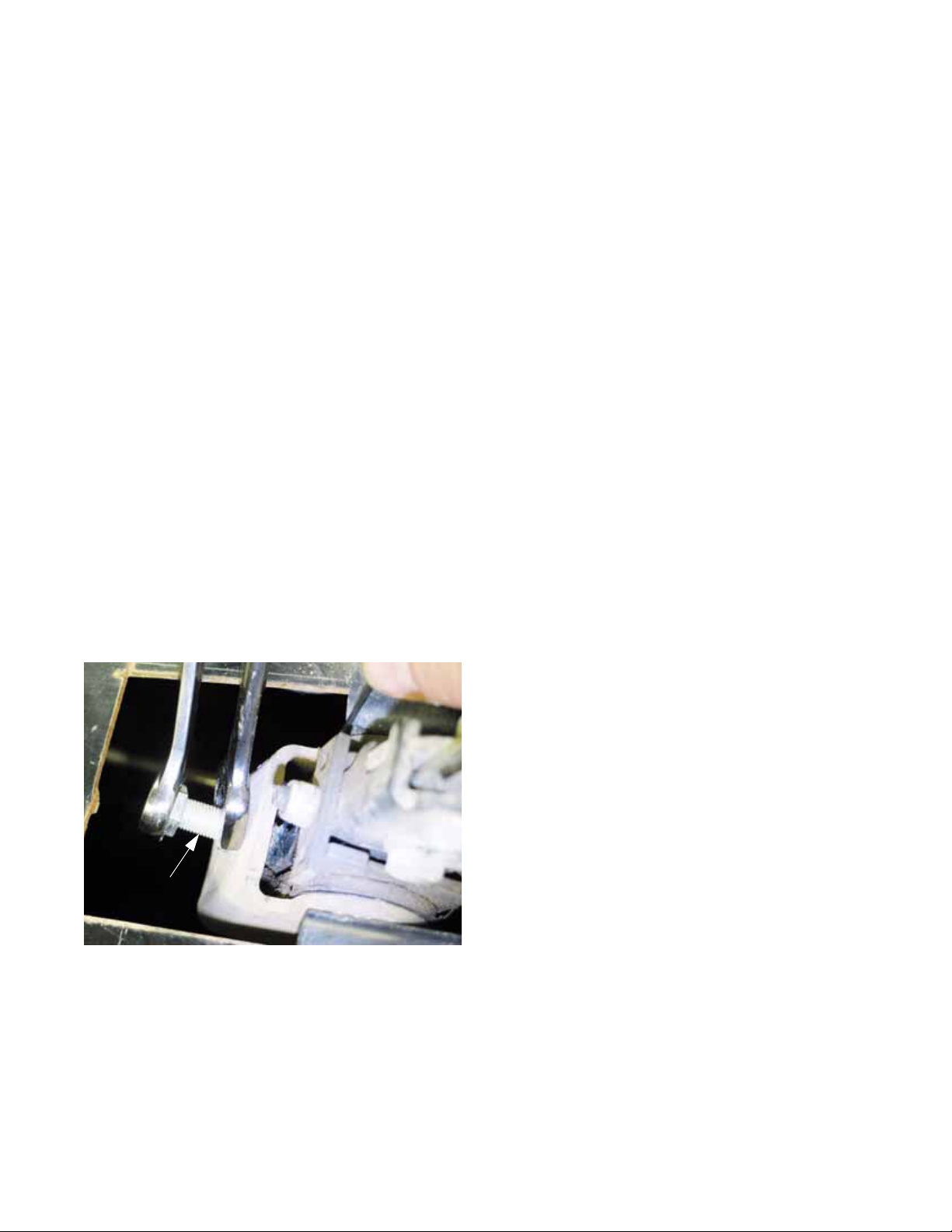
6. The caliper can be adjusted using the screw and
jam nut on the caliper. Us a 7/16” wrench and an
11/16” wrench. See Figure 2.32.
Park brake
caliper
adjustment
Figure 2.32
6.1. After the caliper is in correct adjustment, the linkage that operates it can be adjusted properly.
6.2. The parking brake lever pulls on the cable to
engage the brake when the lever is pulled
upward. See Figure 2.33.
• There is a park brake switch mounted beneath
the lever. The con tact s within the switch are normally closed. As the lever is pulled-up, the
plunger extends from the switch, closing the
contacts.
• Contact closure = 2 notches.
7. Correct adjustment results in full engagement of
the parking brake before the 5th notch, but
allows the lever to come up far enough to close
the contacts in the switch.
8. Checking adjustment: See Figure 2.34.
Park brake light
Park brake lever
in released position
Park brake
switch
Park brake
cable
Figure 2.33
• It moves up in steps that correspond to notches
in a lock plate that the brake lock passes over in
its travel. Full travel = 5 notches.
Figure 2.34
8a. Make the adjustment with the key switch
turned on, but the engine not
the wheels chocked.
8b. Release and reapply the parking brake.
8c. As the bake lever passes the second
notch, the brake light on the instrument
cluster should illuminate. If the transfer
case is not in neutral, an alarm should
sound as well. At this point the slack
should be out of the parking brake cable,
and the arm on the caliper just beginning
to move.
9. By the third notch, drag should be noted when
the drive shaft leading to the rear differential is
turned.
running, and
23
Page 28
Chapter 2- Drive System: CVT and Transfer Case
10. By the fourth notch, it should be impossible to
rotate the drive shaft. See Figure 2.35.
Correct adjustment =
fourth “click” on handle +
tight cable +
brake fully engaged
Figure 2.35
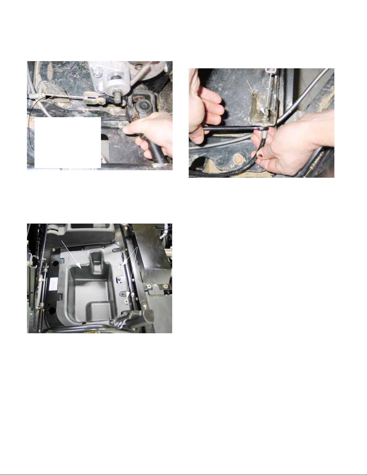
11. To reach the adjustment point for the parking
brake, release the Camloc
fasteners and
R
remove the parcel bin that is located ben eath the
driver’s seat. See Figure 2.36.
Parcel bin
Camloc
R
fasteners
11.1. Adjustment can be made using a pair of 1/2”
wrenches at the anchor point of either end of the
cable. See Figure 2.37.
Adjustment at caliper
end of cable
Figure 2.37
12. Lock the adjustment by snugging the jam nut
against the mounting bracket.
13. Test the operation of the parking brake in a safe
area before returning the vehicle to service. It
should remain stationary with a full load on a 15
degree slope with the parking brake engaged.
NOTE: While this is an extremely capable vehicle, 15 degrees is the maximum angle of operation specified in the Operator’s Manual.
Figure 2.36
CAUTION: Make sure the cover is firmly in place
on the positive battery terminal before adjusting
the cable. Contact between a wrench and the
terminal can short out the battery, causing
potential injury from heat burns, chemical burns,
and battery explosion.
24
Page 29
Chapter 2- Drive System: CVT and Transfer Case
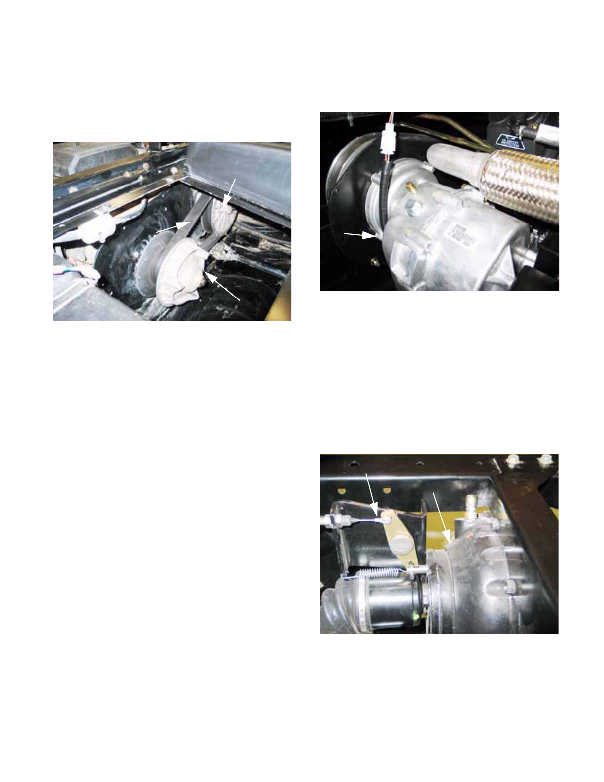
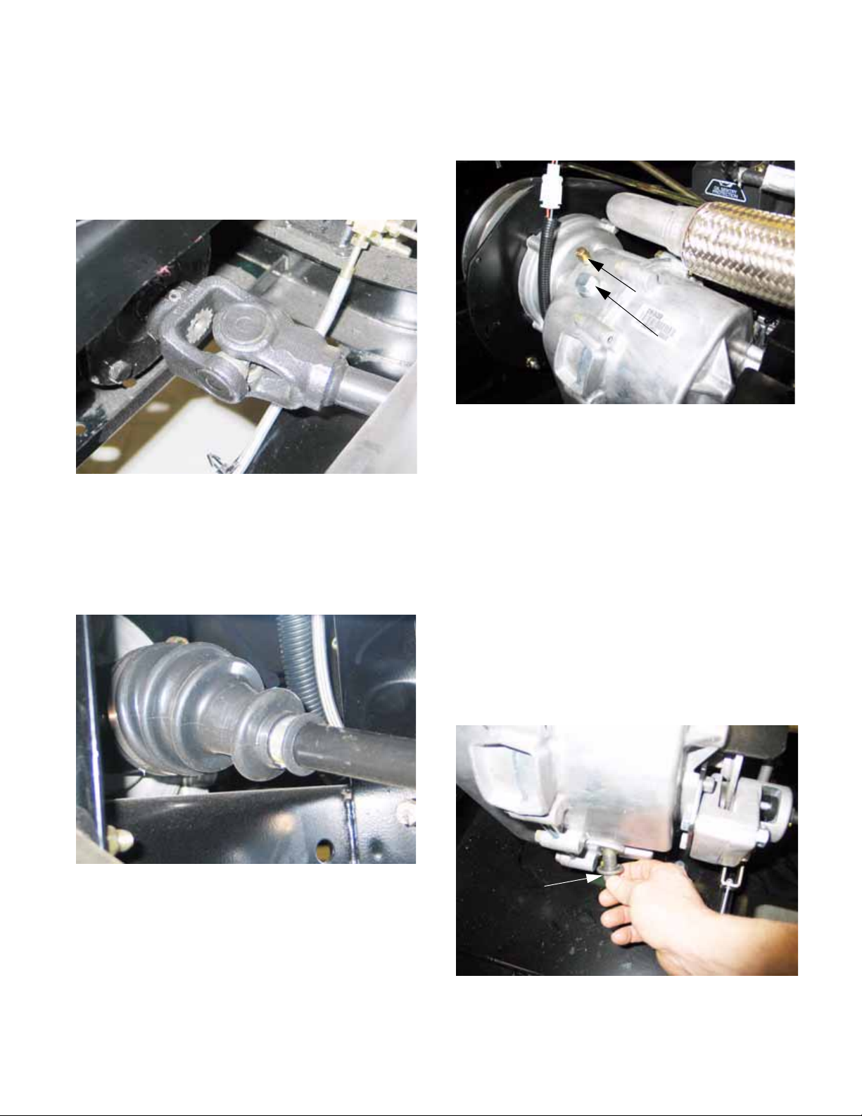
DRIVE SYSTEM SERVICE: LUBRICATION
1. The universal joints in the drive shafts that connect the transfer case to the front and rear differentials are lubricated on assembly, and should
not need further lubrication in their normal service life. See Figure 2.38.
Figure 2.38
3. The transfer case contains 64 fl.oz. (1.9 l.) of
80W-90 Low Foam Oil (Cub Cadet P/N: 737-
04040). See Figure 2.40.
Vent
Fill plug
Figure 2.40
• The transfer case oil should be changed after
the first 5 hrs. of use, 50 hrs. of use, and at 500
hr. intervals thereafter.
2. The constant velocity (Rzeppa type) joints in
the axle shafts that drive the wheels are lubricated on assembly, and should need no further
lubrication in their normal service life.
See Figure 2.39.
Figure 2.39
NOTE: Grease is contained in the constant
velocity joint boots. If a boot is damaged, the
grease will get contaminated. Once the grease
is contaminated, accelerated wear and joint failure will occur. Replace any damaged boot as
soon as possible. Clean and inspect the boots
regularly.
• Inspect the transfer case vent at 100 hr. intervals. A blocked vent will cause fluid loss.
• The transfer case gear lube should be checked
at 100 hr. intervals, or more frequently if fluid
loss is noticed.
• In the event of fluid loss, identify and repair the
leak as soon as possible to prevent catastrophic
failure of the transfer case, disabling the vehicle.
4. To check the fluid in the transfer case:
See Figure 2.41.
Transfer case
level plug
Figure 2.41
25
Page 30
Chapter 2- Drive System: CVT and Transfer Case
5. 13.4. Transfer case, continued...
5a. Park the vehicle on a firm level surface.
5b. Allow the engine and drive system to cool
to ambient temperature.
5c. Tilt the cargo box up.
5d. Release the Camloc
away the engine cover.
5e. Clean the area surrounding the fill plug and
level plug.
5f. Remove the level plug using a 5/8”
wrench, and check for the presence of
fluid at a level even with the bottom of the
threads.
5g. Clean the plug and inspect the o-ring seal.
Replace the o-ring if it is suspect.
6. If the fluid level is low, gear lube may be added
through the fill plug near the top of the transfer
case housing. See Figure 2.42.
Fill plug
fasteners and lift
R
6a. The fill plug can be removed with a 5/8”
open-end wrench.
6b. Inspect the gear lube for debris or metal
chafe, then dispose of it properly.
6c. Add gear lube until it begins to dribble out
of the level plug hole.
6d. Replace the fill and level plugs. Snug the
fill plug, and tighten the level plug to at
torque of 10 ft-lbs. (13.5 N-m).
6e. Replace the engine cover.
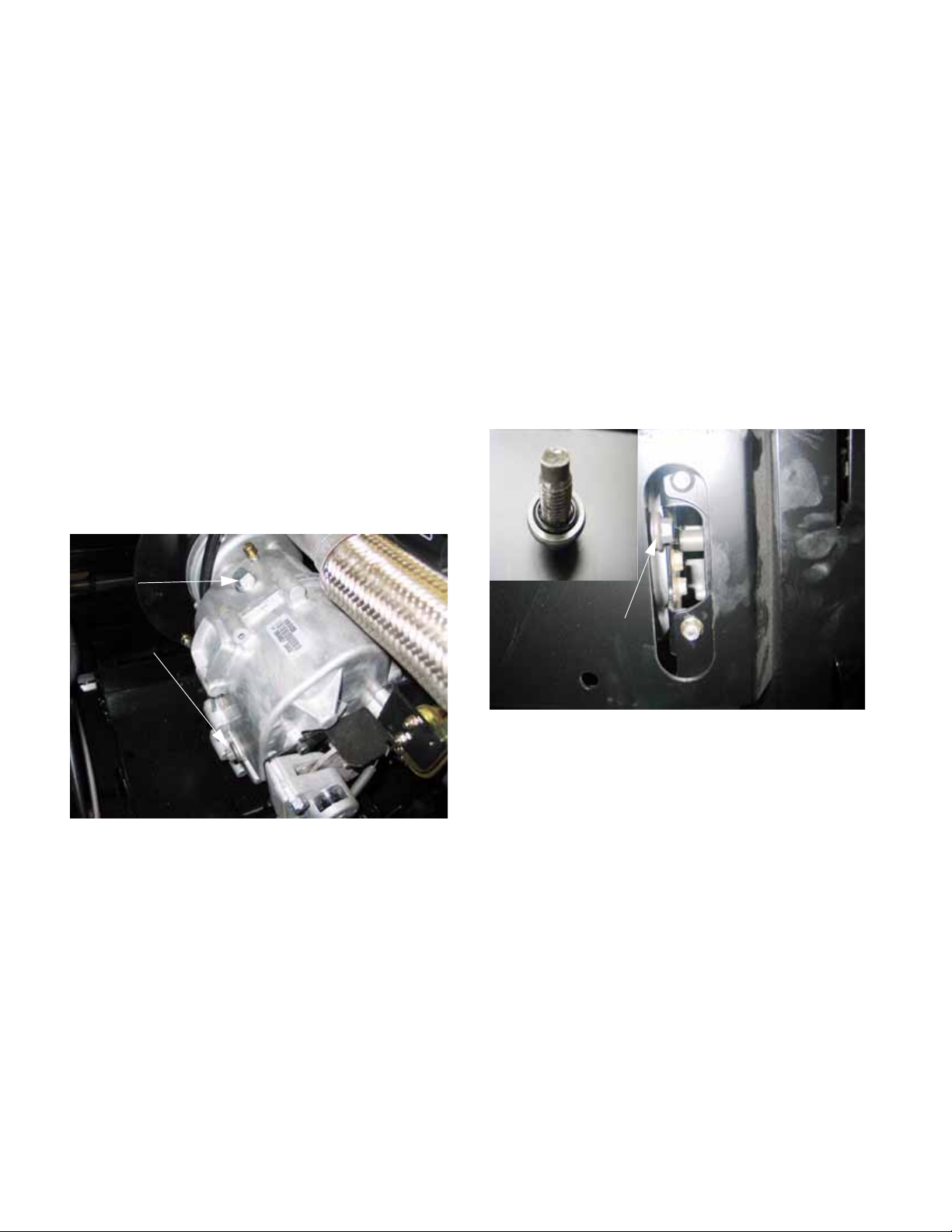
7. To change the lube in the transfer case, follow
the guidelines for checking the fluid. The case
may be drained of lube by removing the plug
using a 5/8” wrench. See Figure 2.43.
Inset: drain plug
O-ring
seal
Level plug
Drain plug access
from beneath vehicle
Figure 2.43
Figure 2.42
26
Page 31

Chapter 2- Drive System: CVT and Transfer Case
DRIVE SYSTEM SERVICE: TRANSFER CASE
REMOVAL WITH KOHLER ENGINE
1. Remove the cargo box from the vehicle:
See Figure 2.44.
Attachment clip
Lift assist
cylinder
Cargo box
hinge bolt
(1 per side)
Figure 2.44
1a. Lift and support the cargo box.
1b. Pry-off the retainer that holds the lift assist
cylinder to the cargo box.
1c. Carefully lower the cargo box. Use a length
of 2X4 dimensional lumber to block the
latch that normally secures the cargo box
in the down position.
1d. Remove the nuts and bolts that secure the
cargo box to the frame using a pair of 9/
16” wrenches.
1e. With the help of an assistant or a mechani-
cal lifting device, slide the cargo box off
the back of the frame and remove it from
the vehicle.
4. Disconnect the black cable from the negative
terminal on the battery using a 10mm wrench.
5. Remove the CVT belt and pulleys as described
in the DRIVE SYSTEM: CVT BELT AND PULLEYS section of this manual. See Figure 2.45.
CVT
removed
Figure 2.45
6. Remove the four bolts that hold the heavy steel
engine / transmission plate using a 1/2” wrench.
7. Remove the four bolts that hold the engine /
transmission plate to the engine using a 9/16”
wrench. The bolts pass through a spacer
between the plate and the engine.
NOTE: It is not necessary to remove the universal joint guard from the plate.
8. Carefully lift the plate out of the engine bay. It is
most easily removed through the opening under
the passenger’s seat. See Figure 2.46.
2. Lift and safely support the vehicle.
3. Release the Camloc
engine cover and remove the engine cover.
fasteners that secure the
R
Figure 2.46
27
Page 32
Chapter 2- Drive System: CVT and Transfer Case
9. Confirm that the transfer case is in neutral.
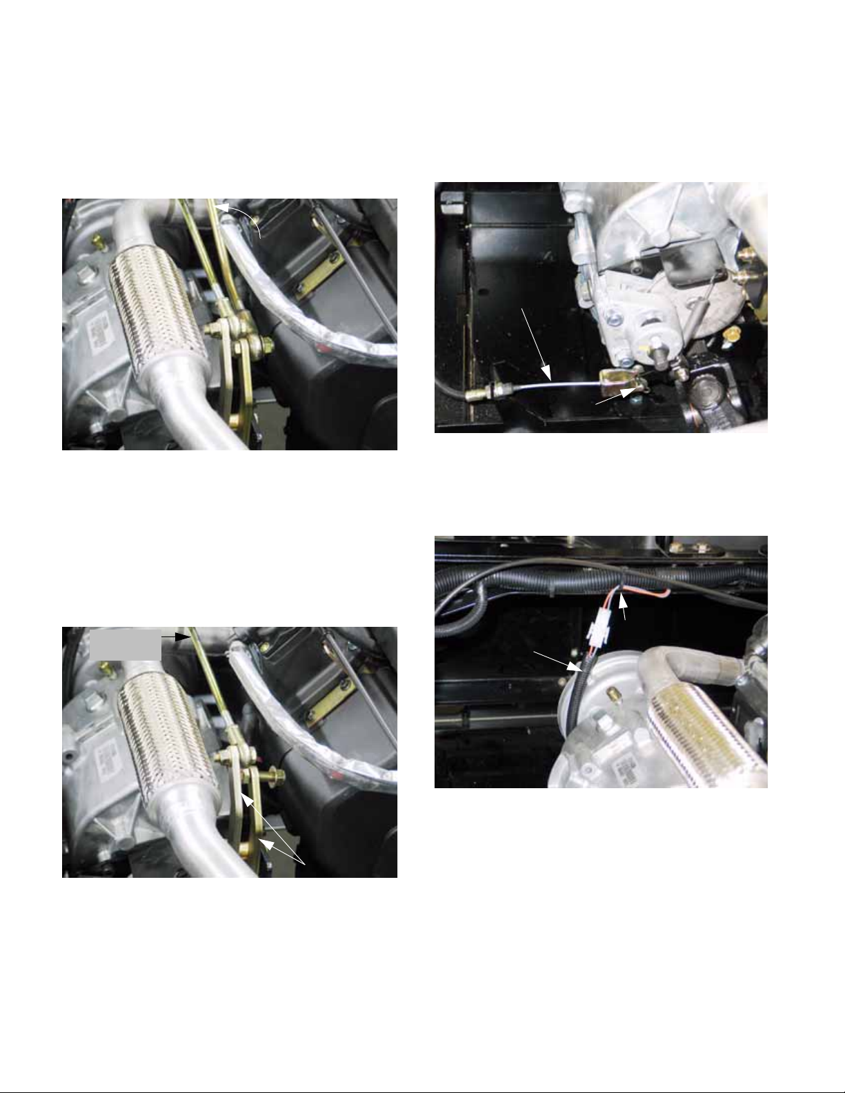
10. Disconnect the heavy Forward-Neutral-Reverse
shift rod from the shift arm mounted to the transfer case. use a pair of 9/16” wrenches.
See Figure 2.47.
ForwardNeutralReverse
rod
Figure 2.47
11. Disconnect the front of the Forwar d- Ne ut ra lReverse shift rod from the Hurst shift mechanism by removing the hairpin clip and tugging
the rod toward the right side of the vehicle.
14. Confirm that the parking brake is released.
15. Disconnect the parking brake cable from the
parking brake caliper by removing the hairpin
clip and clevis pin. See Figure 2.49.
Parking brake
cable
Clevis pin
Figure 2.49
16. Disconnect the transfer case safety switch harness (orange and gray wires) from the main harness. See Figure 2.50.
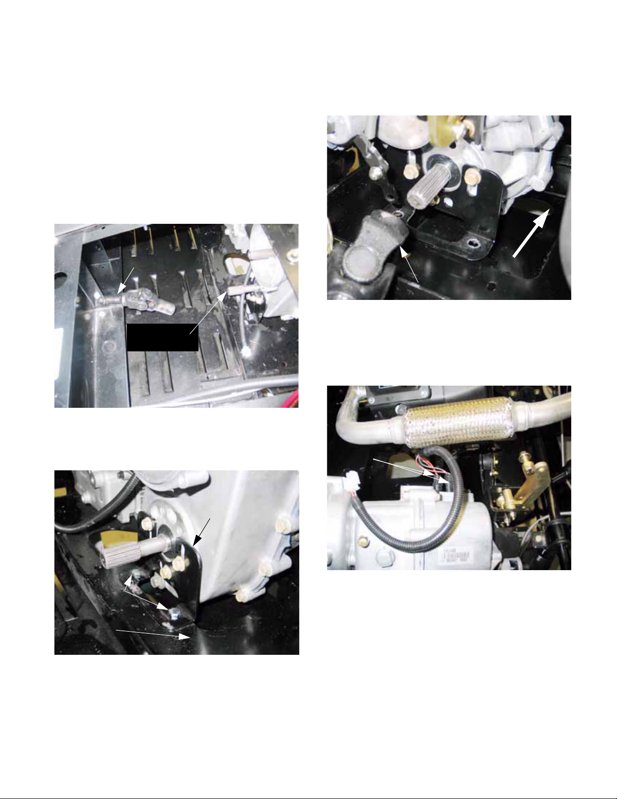
12. Disconnect the lighter Low-range shift rod from
the shift arm mounted to the transfer case. Use
a pair of 1/2” wrenches. See Figure 2.48.
Low-range
shift rod
Transmission
shift arms
Figure 2.48
13. Disconnect the front of the Low-range shift rod
from the Hurst shift mechanism by removing the
hairpin clip and tugging the rod toward the left
side of the vehicle.
Main harness
Transfer case
switch harness
Figure 2.50
NOTE: Wire routing outboard of the flange that
surrounds the transfer case input shaft. This
keeps the wires well away from the exhaust system.
NOTE: Do not lose the plastic bushings.
28
Page 33
Chapter 2- Drive System: CVT and Transfer Case
17. Lift and safely support the utility vehicle, as
described in the LIFTING AND SUPPORTING
section of this manual.
18. Drain the transfer case lube into an appropriate
container, as described in the DRIVE SYSTEM
SERVICE: LUBRICATION section of this manual.
19. Disconnect the front drive shaft, as described in
the DRIVE SYSTEM SERVICE: DRIVE SHAFT
TO FRONT DIFFERENTIAL section of this manual. See Figure 2.51.
Front drive shaft
Output shaft
(transfer case)
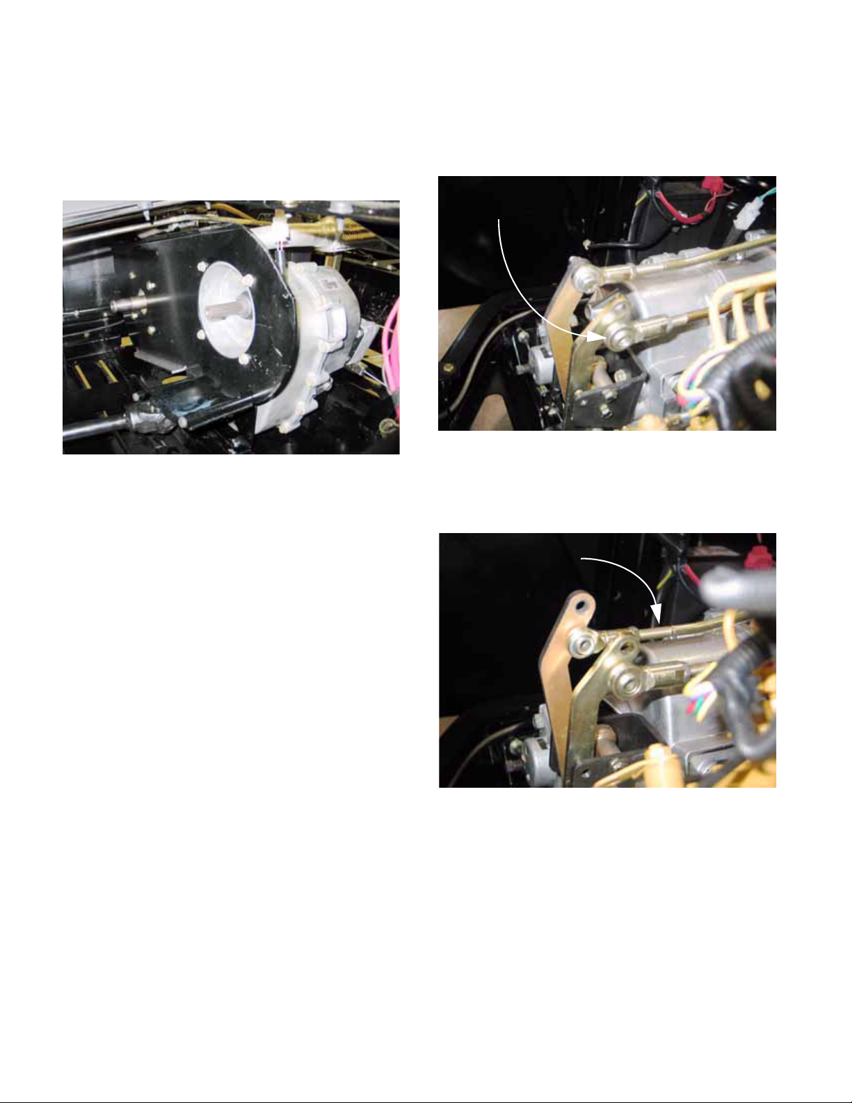
21. Slide the transfer case forward to disengage the
drive shaft that connects it to the rear differ ential.
See Figure 2.53.
Transfer
case
Rear drive shaft
Figure 2.53
22. Tilt the transfer case rearward, so that the shift
linkages clear the bottom of the exhaust system,
and slide it to the left of the vehicle.
See Figure 2.54.
Figure 2.51
20. Unbolt the transfer case brackets from the tray
using a pair of 1/2” wrenches. See Figure 2.52.
Transfer case
mounting bracket
Unbolt here
Engine/ transmission
mounting tray
Figure 2.52
NOTE: The nuts are easily accessible through
access slots in the bottom of the cradle.
Neutral switches
(2X)
Figure 2.54
NOTE: Do NOT unbolt the transfer case from
the brackets that connect it to the tray.
29
Page 34

Chapter 2- Drive System: CVT and Transfer Case
23. Disconnect the transfer case wiring harness
from the two neutral safety switches, and
remove it. This will prevent the harness and
switches from being damaged when the transfer
case is removed.
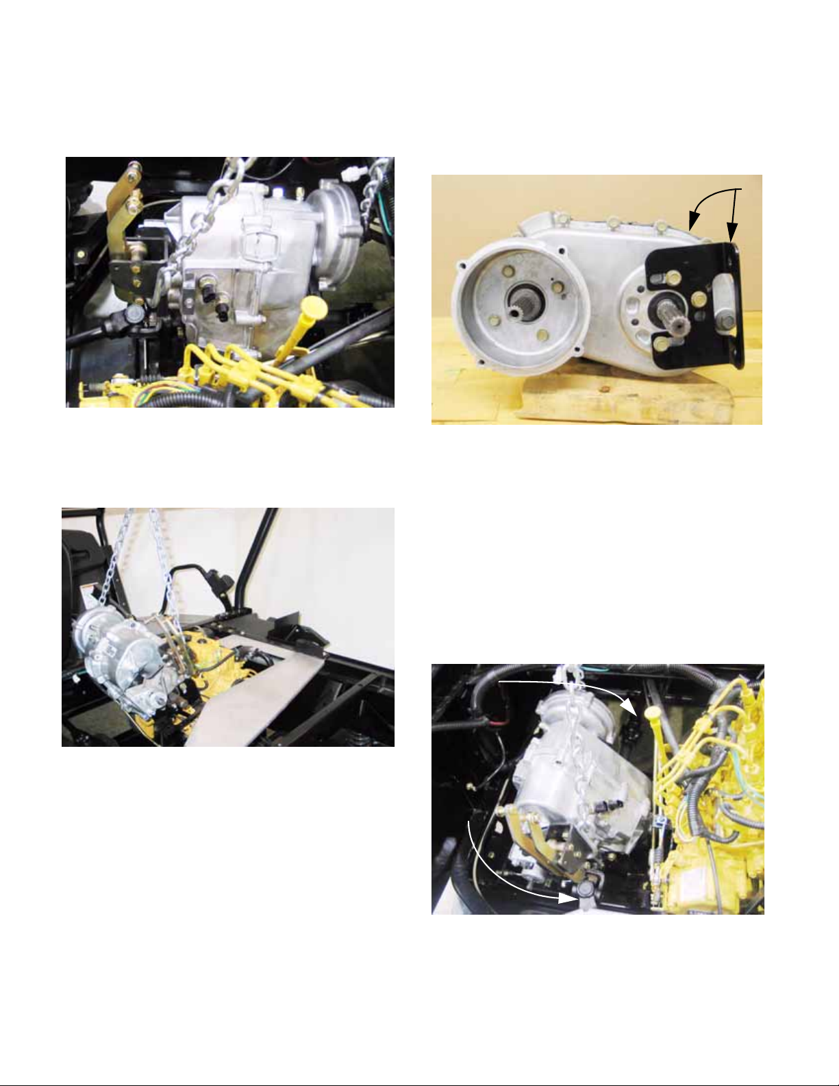
24. Carefully lift the transfer case and brackets out
of the vehicle.
25. If the transfer case is to be disassembled, it is
best to simply leave the brackets attached to the
housing, so that their position is not disturbed.
26. If the transfer case is to be replaced, matchmark the position of each mounting bracket so
that it can be installed in an identical position on
the new transfer case. See Figure 2.55.
27a. Place the transfer case in the engine bay
with sufficient access to connect the
transfer case wiring harness, and install
the harness.
27b. Move the transfer case into it’s mounting
position in the drive system tray, connecting the rear drive shaft to the rear output
shaft in the process.
27c. Secure the transfer case with the four sets
of 5/16” -18 nuts and bolts, but do not fully
tighten the fasteners.
27d. Connect the front drive shaft to the front
output shaft of the transfer case, and reattach the front differential as descr ibed in
the DRIVE SYSTEM SERVICE: DRIVE
SHAFT TO FRONT DIFFERENTIAL section of this manual.
27e. Apply a small amount of thread locking
compound such as Loctite
all of the screws that hold the engine /
transmission plate to the engine and the
transfer case.
242 (blue) to
R
Figure 2.55
27. Installation Notes: Transfer Case Alignment and
Positioning.
Item ft-lbs N-m
CVT driving element 32-36 43-49
CVT driven element 70-80 95-109
Engine / transmission
12 16
plate to transmission
Engine / transmission
18 24
plate to engine
Transmission brack-
32-36 43-49
ets to engine tray
Lug nuts 65-75 88-102
27f. Position the plate, along with the spacer
that fits between the plate and the mounting boss on the engine, and secure it with
one screw to the engine and one screw to
the transfer case.
27g. Confirm that the plate is properly seated
over the mounting boss on the transfer
case, and that the screw holes are properly aligned, then install all the screws that
secure the plate and spacer. Tighten
them to the torque specified in table....
27h. Tighten all the fasteners that hold the
transfer case to the drive system cradle.
Refer to the accompanying table for
torque specifications.
28. Installation Notes: Drive Connections
28a. Apply a sparing amount of anti-seize com-
pound to the splined joint at each end or
the rear driveshaft.
NOTE: If too much anti-seize compound is
applied to the splined connection on the back of
the transfer case, centrifugal force will sling it
onto the parking brake rotor when the vehicle is
in motion.
28b. Secure the rear driveshaft to the rear diffe r-
ential using a new tension pin.
30
Page 35

Chapter 2- Drive System: CVT and Transfer Case
28c. Install the CVT as described in the DRIVE
SYSTEM SERVICE:CVT BELT AND
PULLEYS section of this manual.
29. Make the remaining electrical and mechanical
connections:
29a. Connect the transfer case safety switch
harness to the main harness, confirming
that it is properly routed.
29b. Install the two gear shift rods.
NOTE: Both bolts that connect the shift rods to
the shift arms should be installed with the heads
between the arms. Both nuts should be installed
outboard of each arm.
NOTE: Both shift rods attach to the side of their
shift arm that is nearest the engine.
29c. Connect the parking brake cable.
29d. Connect the negative battery cable.
30. Make the final pre-operational checks:
30a. Confirm that the transfer case contains
64fl. oz. (1.9l.) of Shell Dentax 80W-90
Low Foam Oil, as described in the DRIVE
SYSTEM SERVICE: LUBRICATION section of this manual.
30b. The gear selector should operate properly,
as described in the DRIVE SYSTEM
ADJUSTMENTS: TRANSFER CASE
SHIFT LINKAGE section of this manual.
30c. The parking brake should operate properly ,
as described in the DRIVE SYSTEM
ADJUSTMENT: PARKING BRAKE section of this manual.
31. Install the rear wheel and tire that were previously removed. Apply the parking brake and
tighten the lugs to the specified torque.
32. Confirm that no unsafe conditions will result from
the operation of the engine and drive system.
32a. Run, test, and adjust the drive system if
needed.
DRIVE SYSTEM SERVICE: TRANSFER CASE
REMOVAL WITH CATERPILLAR ENGINE
1. Remove the cargo box from the vehicle:
See Figure 2.56.
Attachment clip
Lift assist
cylinder
Cargo box
hinge bolt
(1 per side)
Figure 2.56
1a. Lift and support the cargo box.
1b. Pry-off the retainer that holds the lif t assi st
cylinder to the cargo box.
1c. Carefully lower the cargo box. Use a
length of 2X4 dimensional lumber to block
the latch that normally secures the cargo
box in the down position.
1d. Remove the nuts and bolts that secure the
cargo box to the frame using a pair of 9/
16” wrenches.
1e. With the help of an assistant or a mechan-
ical lifting device, slide the cargo box off
the back of the frame and remove it from
the vehicle.
2. Lift and safely support the vehicle.
3. Release the Camloc® fasteners that secure the
engine cover and remove the engine cover.
32b. Check for any fluid leaks.
32c. Install the cargo box.
32d. Make a visual inspection of all relevant
hardware before lowering the vehicle to
the ground and returning it to service.
31
Page 36
Chapter 2- Drive System: CVT and Transfer Case
4. Disconnect the black cable from the negative
terminal on the battery using a 10mm wrench.
5. Remove the CVT belt and pulleys as described
in the DRIVE SYSTEM: CVT BELT AND PULLEYS section of this manual. See Figure 2.57.
CVT
removed
Figure 2.57
6. Remove the four bolts that hold the heavy steel
engine / transmission plate using a 1/2” wrench.
7. Remove the four bolts that hold the engine /
transmission plate to the engine using a 9/16”
wrench. The bolts pass through a spacer
between the plate and the engine.
10. Disconnect the heavy Forward-Neutral-Reverse
shift rod from the shift arm mounted to the transfer case. use a pair of 9/16” wrenches.
See Figure 2.58.
Forward-Neutral-Reverse
shift rod
Figure 2.58
11. Disconnect the lighter Low-range shift rod from
the shift arm mounted to the transfer case. Use
a pair of 1/2” wrenches. See Figure 2.59.
Low-range shift rod
NOTE: It is not necessary to remove the universal joint guard from the plate.
8. Carefully lift the plate out of the engine bay. It is
most easily removed through the opening under
the passenger’s seat.
9. Confirm that the transfer case is in neutral.
Figure 2.59
12. Move the shift rods out of the way.
13. Confirm that the parking brake is released.
32
Page 37

Chapter 2- Drive System: CVT and Transfer Case
14. Disconnect the parking brake cable from the
parking brake caliper by removing the hairpin
clip and clevis pin. See Figure 2.60.
Parking brake
cable
Clevis pin
Figure 2.60
15. Disconnect the transfer case safety switch harness (orange and gray wires) from the main harness. See Figure 2.61.
16. Lift and safely support the utility vehicle, as
described in the LIFTING AND SUPPORTING
section of this manual.
17. Drain the transfer case lube into an appropriate
container, as described in the DRIVE SYSTEM
SERVICE: LUBRICATION section of this manual.
18. Unbolt the transfer case brackets from the tray
using a pair of 1/2” wrenches. See Figure 2.62.
Unbolt here
Transfer case
bracket
Main harness
Transfer case
switch harness
Figure 2.61
NOTE: Wire routing outboard of the flange that
surrounds the transfer case input shaft. This
keeps the wires well away from the exhaust system.
Figure 2.62
NOTE: The nuts are easily accessible through
access slots in the bottom of the cradle.
NOTE: Do NOT unbolt the transfer case from
the brackets.
19. Slide the transfer case slightly away from the
engine, and disconnect the transfer case wiring
harness from the two neutral safety switches,
and remove the harness. See Figure 2.63.
Safety switches
33
Figure 2.63
Page 38
Chapter 2- Drive System: CVT and Transfer Case
20. Attach a lifting apparatus to the transfer case,
being careful not to fowl the linkages.
See Figure 2.64.
Figure 2.64
21. Carefully lift the transfer case and brackets out
of the vehicle, disconnecting the driveshafts as it
comes up. See Figure 2.65.
23. If the transfer case is to be replaced, matchmark the position of each mounting bracket so
that it can be installed in an identical position on
the new transfer case. See Figure 2.66.
Transfer case
Figure 2.66
24. Installation Notes: T ransfer Case Alig nme nt and
Positioning.
Mounting bracket
Figure 2.65
22. If the transfer case is to be disassembled, it is
best to simply leave the brackets attached to the
housing, so that their position is not disturbed.
24a. Apply a sparing amount of anti-seize
compound to the splined joints at the
transfer case end of each driveshaft.
24b. Use a lifting apparatus to suspend the
transfer case in the engine bay.
24c. Carefully lower the transfer case into posi-
tion, connecting the front and rear driveshafts as it is lowered. See Figure 2.67.
Front drive shaft
Rear drive
shaft
34
Figure 2.67
24d. Connect the transfer case wiring harness
to the two neutral safety switches before
securing the transfer case to the tray.
Page 39

Chapter 2- Drive System: CVT and Transfer Case
24e. Move the transfer case into it’s mounting
position in the drive system tray.
24f. Secure the transfer case with the four sets
of 5/16” -18 nuts and bolts, but do no t fully
tighten the fasteners.
24g. Apply a small amount of thread locking
compound such as Loctite® 242 (blue) to
all of the screws that hold the engine /
transmission plate to the engine and the
transfer case.
24h. Position the plate, and secure it with one
screw to the engine and one screw to the
transfer case.
24i. Confirm that the plate is properly seated
over the mounting boss on the transfer
case, and that the screw holes are properly aligned, then install all the screws that
secure the plate and spacer. Tighten
them to the torque specified in table.
24j. Tighten all the fasteners that hold the
transfer case and the engine/transfer
case in position. Refer to the accompany-
ing table for torque specifications.
Item ft-lbs N-m
26. Make the remaining electrical an d me ch a nic al
connections:
26a. Connect the transfer case safety switch
harness to the main harness, confirming
that it is properly routed.
26b. Connect the two gear shift rods.
NOTE: Both bolts that connect the shift rods to
the shift arms should be installed with the heads
between the arms. Both nuts should be installed
outboard of the arms.
NOTE: Both shift rods attach to the side of their
shift arm that is nearest the engine.
26c. Connect the parking brake cable.
26d. Connect the negative battery cable.
27. Make the final pre-operational checks:
27a. Confirm that the transfer case contains
64fl. oz. (1.9l.) of 80W-90 Low Foam Oil,
as described in the DRIVE SYSTEM
SERVICE: LUBRICATION section of this
manual.
27b. The gear selector should operate properly,
as described in the DRIVE SYSTEM
ADJUSTMENTS: TRANSFER CASE
SHIFT LINKAGE section of this manual.
CVT driving element 32-36 43-49
CVT driven element 70-80 95-109
Engine / transmission
12 16
plate to transmission
Engine / transmission
18 24
plate to engine
Transmission brack-
32-36 43-49
ets to engine tray
Lug nuts 65-75 88-102
25. Install the CVT as described in the DRIVE SYSTEM SERVICE:CVT BELT AND PULLEYS section of this manual.
27c. The parking brake should operate prop-
erly, as described in the DRIVE SYSTEM
ADJUSTMENT: PARKING BRAKE section of this manual.
28. Install the rear wheel and tire that were previously removed. Apply the parking brake and
tighten the lugs to the specified torque.
29. Lower the vehicle to the groun d.
30. Confirm that no unsafe conditions will result from
the operation of the engine and drive system.
30a. Run, test, and adjust the drive system if
needed.
30b. Check for any fluid leaks.
30c. Install the cargo box.
30d. Make a visual inspection of all relevant
hardware before lowering the vehicle to
the ground and returning it to service.
35
Page 40

Chapter 2- Drive System: CVT and Transfer Case
DRIVE SYSTEM BENCH SERVICE:
TRANSFER CASE DISASSEMBLY
1. Preliminary steps:
1a. Clean-up and visually examine the transfer
case for wear and damage that may make
it unfeasible to repair.
1b. Unless there is a specific reason to
remove the mounting brackets, they are
best left in place.
1c. If the gear lube was not previously
drained, remove the drain plug using a
13mm wrench and allow the fluid to drain
into a clean pan. See Figure 2.68.
1e. Examine the contents of the drain pan and
the residue that is stuck to the magnetic
tip of the drain plug. See Figure 2.70.
Residue inside
transfer case
Figure 2.70
1f. If not previously removed, take the washer
and spacer off of the input shaft.
See Figure 2.71.
Drain plug
Gasket
magnetic tip
Figure 2.68
1d. Remove the fill plug from the side of the
transfer case using a 5/8” wrench. This
will let air enter the case faster, speeding
the draining process. See Figure 2.69.
Level plug
(O-ring seal)
Spacer
Washer
Input shaft
Figure 2.71
Figure 2.69
36
Page 41

Chapter 2- Drive System: CVT and Transfer Case
2. If the parking brake is being remove d for transfer
to a replacement transfer case:
2a. Remove the screws that hold the caliper
bracket to the transfer case housing using
a T-45 driver. See Figure 2.72.
Brake caliper
bracket screws
Figure 2.72
2b. Draw-out and pivot the caliper and rotor as
an assembly so that they clear the shift
arm assembly , an d remove them from the
transfer case. See Figure 2.73.
3. If the parking brake is being removed for brake
replacement or other service:
NOTE: The inner brake pad is epoxied into the
caliper. Because the inner pad cannot be
replaced, the caliper is offered only as a complete assembly. Individual parts are not available.
3a. Unhook and remove the return spring.
See Figure 2.74.
Long end
goes up
Unhook the
bottom end
first
Figure 2.74
Figure 2.73
2c. Installation is essentially the reversal of
the removal process.
• The friction surfaces of the pads and rotor must
be clean and in good condition.
• Tighten the nuts according to the torque table
that accompanies this section of the chapter.
3b. Remove the two nuts that hold the caliper
to the caliper bracket using a pair of 9/16”
wrenches. See Figure 2.75.
Bracket
Bolts
Shims
Caliper
Nuts
Figure 2.75
37
Page 42

Chapter 2- Drive System: CVT and Transfer Case
3c. Remove the outer caliper housing.
See Figure 2.76.
Outer caliper
housing
Figure 2.76
3d. Slip the rotor off of the brake shaft. It will
clear the shift arm assembly.
See Figure 2.77.
3e. Slide the inner caliper housing off of the
two bolts that locate it. See Figure 2.78.
Inner caliper
housing
Figure 2.78
3f. Installation is essentially the reversal of
the removal process.
4. Parking brake operation and construction:
Brake rotor:
flat side out
Figure 2.77
• The friction surfaces of the pads and rotor must
be clean and in good condition.
• Tighten the nuts according to the torque table
that accompanies this section of the chapter.
NOTE: Caliper operation: See Figure 2.79.
Cam arm
“Bullet”: flat side visible
Brake backing plate
Brake pad
Long
side
Long
side
short side
Figure 2.79
Short side
Long
side
• The caliper is actuated by a cam-arm that forces
a steel “bullet” against a heavy steel backing
plate.
• The backing plate and pad are “doubleD”
shaped, although one flat is longer than the
other.
38
Page 43

Chapter 2- Drive System: CVT and Transfer Case
• The adjustment screw acts by moving the contact point that the cam arm pivots against.
See Figure 2.80.
Cam arm
“Bullet”
Figure 2.80
NOTE: The brake pads are thick enough that
they will have a long service life. While service
brakes are used to stop the vehicle, parking
brakes merely hold it once it is stopped. If the
parking brakes wear prematurely, confirm that
the mechanism is not sticking in the applied
position. If it is not, operator technique (driving
with the parking brake applied) is probably the
cause.
5. Remove the shift arm assembly:
5a. Disconnect the shift arms from the shift
shafts using a 3/16” allen wrench.
See Figure 2.81.
Adjustment
screw
Jam nut
5b. Loosen but do not remove the nut and bolt
that the Low-range shift arm pivots on
using a pair of 7/16” wrenches.
NOTE: L
5c. Remove the nut and bolt that the Forward-
NOTE: The ends of both shift-shafts are Dshaped. The flat of each D should be oriented
toward the arm that actuates the shaft.
See Figure 2.83.
ong arm = Low range
Neutral-Reverse shift arm pivots on using
a pair of 7/16” wrenches, and remove the
arm from the bracket. See Figure 2.82.
Low gear shift arm Bracket
F-N-R
shift arm
Tube
Plastic bushings
Figure 2.82
Low range
shift shaft
Shift s hafts
Shift arms
F-N-R shift shaft
Shouldered
socket-head
cap screws
Figure 2.83
Figure 2.81
39
Page 44

Chapter 2- Drive System: CVT and Transfer Case
5d. Check the plastic split-busings for wear.
They are inexpensive, and replacing them
if there is any significant wear will
improve shift action. See Figure 2.84.
Bolt
Nut
Plastic split
bushing
plastic
split bushing
spacer tube
Figure 2.84
6. Remove the safety switches and detents:
6a. Unscrew and remove the two neutral
safety switches using a 7/8” wrench.
See Figure 2.85.
Neutral
safety
switches
6b. Remove the detent plate using a 3/8”
wrench. See Figure 2.86.
Detent plate
Detent
springs
Figure 2.86
6c. Remove the detent springs.
6d. Clear any sealant flash from the detent
bores, and remove the detent balls using
a magnet, if necessary.
7. Separate the case halves:
7a. Remove the two sets of nuts and bolts that
hold the case halves together through untapped holes. Use a pair of 1/2”
wrenches.
7b. Support the transfer case by the housing,
with the screws that secure the case
halves together facing up.
See Figure 2.87.
Figure 2.85
Figure 2.87
40
Page 45

Chapter 2- Drive System: CVT and Transfer Case
7c. Remove the four screws that hold the
adaptor housing to the transfer case using
a 1/2” wrench. See Figure 2.88.
Adaptor
housing
Tension
pin
Figure 2.88
7d. Lift the adaptor housing off of the transfer
case, noting the tension pin that indexes
the two housings to each-other.
7f. Remove the screws that hold the case
halves together using a 1/2” wrench.
7g. Gently separate the case halves using the
three pry points, and a soft hamme r if necessary . Do not pr y against the mating surfaces to separate the case halves.
See Figure 2.90.
Lift left case half
Right case
half (down)
Figure 2.90
7e. Pry or cut the hog ring off of the input
shaft. Discard the hog ring and replace it
with a new one when the transfer case is
being assembled. See Figure 2.89.
Input shaft
Hob ring
Figure 2.89
NOTE: The portion of the case that was lifted-off
is identified as the “Left Case Half”. The other is
the “Right Case Half”.
8. Input shaft:
NOTE: If new pinion gears, and the middle shaf t
gears that mate with them are installed in the
transfer case, orientation of the gears on the
shaft is unimportant. Once a wear pattern is
established on the gear teeth, orient the g ears to
maintain that wear pattern. See Figure 2.91.
Pinon gear Middle shaft gear
41
NOTE: wear pattern
Figure 2.91
Page 46

Chapter 2- Drive System: CVT and Transfer Case
8a. Lift the input shaft assembly straight out of
the case. See Figure 2.92.
Input shaft assembly
Middle shaft
Figure 2.92
8b. The input shaft assembly consists of:
See Figure 2.93.
.060” shim washer 2-3/16” Spacer tube
Output shaft
9. Middle shaft and output shaft:
NOTE: The middle shaft gears all have features
that dictate their orientation during assembly.
9a. Remove and discard the square-section
hog-ring from the end of the middle shaft.
See Figure 2.94.
Square-section hog ring
Figure 2.94
15-tooth low pinion 22-tooth forward
(high) pinion
Reverse pinion
Input shaft
Figure 2.93
• A .060” (1.52mm) flat washer rides between the
low-gear pinion and the bearing that su pp or ts
the input shaft in the left case half.
• A 15-tooth low-gear pinion is positioned on the
first set of splines within the left case half.
• A 2-3/16” (55cm) spacer is placed between the
low gear pinion and the high-gear pinion.
• A 22-tooth high-gear pinion rides next to the
reverse pinion that is machined into the shaft.
9b. Lift the 40-tooth low gear off of the middle
shaft, along with the heavy washer that
separates it from the hog ring.
See Figure 2.95.
40-tooth
low gear
washer
Figure 2.95
NOTE: It may take some wiggling, tugging, and
turning to loosen the gear, but it will come off.
42
Page 47

Chapter 2- Drive System: CVT and Transfer Case
9c. Lift the low gear shift shaft assembly (shift
shaft and fork) out of the right side housing. See Figure 2.96.
Low gear
shift collar
Low gear
shift shaft
Figure 2.96
9d. Lift the spacer and 69-tooth bull gear of f of
the output shaft. See Figure 2.97.
Spacer
Output shaft
Bull gear
(final gear)
9e. Lift the output shaft out of the housing.
See Figure 2.98.
Output shaft
Right side case half
Alignment
dowel
Figure 2.98
9f. Lift the middle shaft assembly out of the
housing. See Figure 2.99.
Middle shaft
Final pinion
33-tooth forward
(High) gear
Figure 2.97
NOTE: If new middle shaft gears that mate with
the bull gear or reverse idler are installed in the
transfer case, orientation of the gears on the
shaft is unimportant. Once a wear pattern is
established on the gear teeth, orient the gears to
maintain that wear pattern
to mark the gear to identify its original orientation.
. It may be necessary
Figure 2.99
9g. The middle shaft assembly consists of:
• The middle shaft.
• The 26-tooth final pinion. The final pinion is held
onto a splined section of the middle shaft by a
snap ring. The flat side of the pinion faces the
ring, while the shouldered side of the pinion
abuts the high gear.
• The 33-tooth high gear spins freely on the middle shaft, held in-place by the final pinion. The
teeth that engage the shift dog face the teeth on
the middle shaft that drive the shift dog.
• The snap ring.
43
Page 48

Chapter 2- Drive System: CVT and Transfer Case
9h. The middle shaft is easily disassembled
using a pair of external snap ring pliers.
See Figure 2.100.
Figure 2.100
9i. Lift the forward-neutral-reverse shift shaft,
shift yoke, spacer, and shift collar out of
the bore that is closer to the output shaft
bearing. See Figure 2.101.
F-N-R shift collar
F-N-R shift shaft
9k. Lift-out the reverse gear a nd washer .
See Figure 2.102.
Reverse gear
washer
Figure 2.102
9l. The reverse idler is the last gear left in the
case, secured by a 1/2”-13 grade-8 cap
screw and flat washer. Remo ve it using a
3/4” wrench.
9m. The reverse idler contains a pair of roller
bearings that ride on a hardened tube.
The tube passes-through a washer that
isolates the reverse idler from the case.
See Figure 2.103.
Spacer
Figure 2.101
9j. The 39-tooth reverse gear will be left rest-
ing in the right hand case, separated from
the bearing that carries the middle shaft
by a .030” (0.76mm) washer.
Reverse Idler
Roller bearings
Steel tube
Washers
Gr.8 bolt
Figure 2.103
NOTE: If new input shaft or reverse idler that
mates with it are installed in the transfer case,
orientation of the gears on the shaft is unimportant. Once a wear pattern is established on the
gear teeth, orient the gears to maint ain that wear
pattern. Mark the gear if necessary.
44
Page 49

Chapter 2- Drive System: CVT and Transfer Case
10. Remove and discard the seals from both halves
of the transfer case housing. See Figure 2.104.
Shift shaft seals
(use hook tool
with caution)
Figure 2.104
NOTE: Use caution not to damage the seal
bores when removing the seals.
11. The bearings need not be removed from the
case unless they are bad. Inspection will be covered in the next section of this chapter. If the
bearings do need to be removed:
11a. The right side case half contains three
bearings. See Figure 2.105.
Bearing seal bores
1 1b. T he lef t side case half con t ains three bea r-
ings: See Figure 2.106.
Left side case half
Middle shaft bearing
Figure 2.106
• The input shaft bearing fits in a shouldered bore
that is open to the outside of the case.
• The middle shaft bearing fits in a blind bore.
• The output shaft bearing fits in a shouldered
bore that is open to the outside of the case.
1 1c. The bearing s that fit in the blind bores may
require a blind bearing puller to remove
them from the case.
Right side case half
Input shaft bearing
Figure 2.105
• The input shaft bearing fits in a blind bore.
• The middle shaft bearing fits in a shouldered
bore that is open to the outside of the case.
• The output shaft bearing fits in a shouldered
bore that is open to the outside of the case.
11d. The bearings that fit in the open bores
may be driven-out by their inner races
ONLY if they are not to be re-used.
11e. The cases may be evenly heated in an
oven to not more than 200 deg.f. (93
deg.c.). This will ease bearing removal
and installation, as will chilling the bearings immediately prior to installation.
CAUTION: DO NOT use a torch to heat the case
halves, as the heat applied by a torch is too
uneven and may distort the case.
45
Page 50

Chapter 2- Drive System: CVT and Transfer Case
DRIVE SYSTEM BENCH SERVICE:
TRANSFER CASE INSPECTION
1. Clean and inspect the case and all internal parts.
NOTE: Most of the inspection process is visual
or tactile. A limited amount of measurement is
necessary, mostly to confirm whether a part that
is usually worn is still serviceable.
1a. Clean all sealant from the mating surfaces
and clean all lubricant and dirt from the
internal and external surfaces.
CAUTION: If the cases are cleaned in solvent,
with the bearings in-place, all solvent must be
cleaned from the bearings. Pay particular attention to the blind bearings. Any solvent that
remains in the transfer case will dramatically cut
the viscosity of the new gear lube, shortening
the life of the freshly rebuilt transfer case.
1b. If the cases are cleaned using detergent
and water, with the bearings in-place,
completely dry the bearings and spray
them with a suitable lubricant such as Cub
Cadet Penetrating Oil (P/N: 737-3037) to
displace any remaining water.
1c. Check the housings for cracks, damage to
machined surfaces, stripped threads.
1d. Check the vent: it should pass air.
1e. Check the bearings for: See Figure 2.107.
Check bearing
in housing
2. Check the middle shaft gears: See
Figure 2.108.
Dog teeth
(serrations)
Shift collar
Gear teeth
Gear
Figure 2.108
2a. The gear teeth are unlikely to be hurt
except in cases of extreme contamination,
corrosion or foreign object damage. In
any of these cases the transfer case is
likely unfeasible to repair.
2b. Check that the dog teeth on the shaft,
gear, and shift collar are not damaged.
NOTE: If the teeth are damaged the cause of
the damage must be corrected. Possible causes
include: operator abuse by shifting gears while
the vehicle is in motion, or shift linkage issues.
2c. The low forward and reverse gears on the
middle shaft both have bearing-material
inserts. Check the inserts for wear.
Figure 2.107
• Rough rotation: rotate them, feel and listen
• Looseness: work the inner race and check for
play .
• Discoloration or obvious signs of damage.
2d. Check the washers: See Figure 2.109.
.030” washers
Replace if worn to less
than .025” (.64mm).
Bearing material
inserts
Reverse Low range
gear (forward) gear
Figure 2.109
46
Page 51

Chapter 2- Drive System: CVT and Transfer Case
3. Check the forward / reverse shift yoke (fork) and
shift collar groove for wear:
3a. Check the thickness of the shift yoke pad
that contacts the shift collar using a
micrometer (preferably) or calipers.
See Figure 2.110.
Checking F-N-R
shift yoke
Figure 2.110
3c. Inspect the shift shaft for wear on the mat-
ing and seal surfaces.
3d. Check that the snap rings are seated in
their grooves. If removed, replace the
snap rings with new ones.
NOTE: if the shift yoke and collar show wear
from a constant thrust load on the shift shaft
(wear, sco ring, or discoloration) the caus e of the
damage must be corrected. It may be a opera tor
abuse by applying force to the Hurst gear selector while the vehicle is in motion, or it may be an
issue with the linkage.
4. Check the low gear shift yoke (fork) and shift collar groove for wear:
4a. Check the thickness of the shift yoke pad
that contacts the shift collar using a
micrometer (preferably) or calipers.
See Figure 2.112.
Checking low-range shift yoke
• The minimum pad thickness on the shift yoke
that moves the forward / reverse shift collar
should be .230” (5.842mm). If it is worn further
there is some chance that the case hardening
will soon be worn through.
3b. Check the forward / reverse shift collar
groove for wear: Use a .035” (.889mm)
feeler-gauge as a go / no-go tool. If the
feeler gauge can be inserted to the base
of the groove in the shift collar, and the
shift yoke is good, replace the shift collar.
See Figure 2.111.
Checking F-N-R
shift collar
Figure 2.112
• The minimum pad thickness on the shift yoke
that moves the forward / reverse shift collar
should be .2225” (5.715mm). If it is worn further
there is some chance that the case hardening
will soon be worn through.
Figure 2.111
47
Page 52

Chapter 2- Drive System: CVT and Transfer Case
4b. Check the forward / neutral / reverse shift
collar groove for wear: Use a .035”
(.889mm) feeler-gauge as a go / no-go
tool. If the feeler gauge can be inserted to
the base of the groove in the shift collar,
and the shift yoke is good, replace the
shift collar. See Figure 2.113.
Checking the F-N-R
shift collar
Figure 2.113
4c. Inspect the shift shaft for wear on the mat-
ing and seal surfaces.
4d. Check that the snap rings are seated in
their grooves. If removed, replace with
new ones.
NOTE: If the shift yoke and collar show wear
from a constant thrust load on the shift shaft
(wear, scorin g, or discoloration) the cause of the
damage must be corrected. It may be operator
abuse by applying force to the Hurst gear selector while the vehicle is in motion, or it may be an
issue with the linkage.
5. The forward, reverse, and low range gears spin
on the middle shaft. Check the bearing contact
surfaces on the middle shaft for wear.
See Figure 2.114.
Bearing contact areas
Figure 2.114
• Any scratch big enough to catch a fingernail in
indicates that the shaft should be polished or
replaced.
• Replace the shaft if metal transfer, eruption, or
discoloration are evident on any of the bearing
surfaces
• All surfaces should be checked at three spots
and in two directions to confirm that the shaft is
straight and round.
• Check the bearing surfaces with a micrometer
(preferably) or calipers. Wear beyond the specified measurement may break-through the heattreated layer of metal.
48
Page 53

Chapter 2- Drive System: CVT and Transfer Case
5a. The bearing surface that the low gear
rides-on (opposite end from the brake
rotor spline, measured inboard from the
snap-ring groove) should be a minimum
of .617” (15.672mm) diameter.
See Figure 2.115.
Smaller set
of dog teeth
Figure 2.115
5b. The bearing surface that the forward gear
rides on (largest cross-section of shaft,
adjacent to large set of dog teeth) should
be a minimum of 1.144” (29.058mm).
See Figure 2.116.
5c. The bearing surface that the reverse gear
rides on (second largest cross-section of
shaft, adjacent to large set of dog teeth)
should be a minimum of .970”
(24.638mm). See Figure 2.117.
Brake spline
Larger set of
dog teeth
Figure 2.117
NOTE: If there is significant wear to any of the
bearing surfaces, it is also very likely that the
corresponding gear will have to be replaced.
The bearing surfaces on the inside diameters of
the low and reverse gears are significantly softer
than the bearing surface of the shaft.
Final pinion gear spline
Larger set
of dog teeth
Figure 2.116
NOTE: The forward gear does not require a
bearing insert because there is a lower speed
differential between the gear and the shaft.
6. Inspect the sleeve that the reverse idler gear
rides-on. If there is any scoring or heat discoloration, replace the sleeve and the reverse idler
gear. See Figure 2.118.
Roller bearings
Hardened
sleeve
Reverse idler
Figure 2.118
49
Page 54
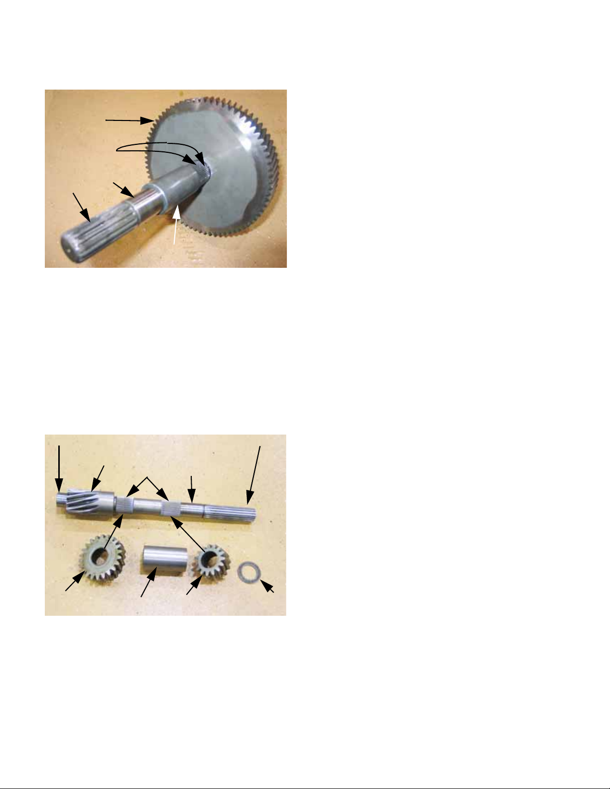
Chapter 2- Drive System: CVT and Transfer Case
7. Inspect output shaft: See Figure 2.119.
Bull gear
Bull gear/shaft
splines
Bearing
contact area
End spline
Spacer
Figure 2.119
7a. Visually check the end splines (for the
front and rear drive shafts)
7b. Visually check the spline that engages the
bull gear.
8a. Visually check:
*The end spline (CVT mounting)
*The reverse pinion (machined onto shaft)
*The spline that engages the Low pinion.
*The spline that engages the high pinion.
*The surfaces that ride in the ball bearings
and seals for galling, fretting, and
scratches.
8b. Damage to the shaft dictates the need to
replace the corresponding bearing or gear
that rides on that part of the shaft.
8c. Check the high gear pinion and low gear
pinion for damage.
NOTE: The gear teeth are unlikely to be hurt
except in cases of extreme contamination, corrosion or foreign object damage. In any of these
cases the transfer case is likely unfeasible to
repair.
8d. Check the hardened flat washer . It should
be .060” (1.52mm) thick.
7c. Check the surfaces that ride in the ball
bearings for galling or fretting. Damage to
this part of the gear also dictates the need
to replace the corresponding bearing.
8. Inspect input shaft: See Figure 2.120.
Bearing pilot End spline
Reverse pinion Bearing
splines contact surface
Forward
(high) pinion
spacer Reverse
pinion
Figure 2.120
.060” washer
50
Page 55

Chapter 2- Drive System: CVT and Transfer Case
DRIVE SYSTEM BENCH SERVICE:
TRANSFER CASE ASSEMBLY
1. Replace any bearings that were removed from
the case halves. See Figure 2.121.
Figure 2.121
1a. The case halves may be heated in hot
water or in an oven prior to installation.
They should not be heated beyond 200
deg.f. (93 deg.c.).
2. Install the reverse idler gear:
2a. Apply a small amount of thread locking
compound such as Loctite 262 (red) to the
threads of the 1/2”-13 bolt that holds the
reverse idler in place.
2b. Apply a small amount of grease such as
Cub Cadet multi-purpose grease (P/N
737-3034) to the bearing inside the gear.
2c. Assemble the bolt, flat washers, spacer
and gear . Use the mark made on removal
or witness marks to maintain the original
gear orientation.
2d. Install the reverse idler in the right case
half and tighten the bolt to a torque of 3240 ft-lbs. (43.4-54.2 N-m).
See Figure 2.122.
CAUTION: DO NOT use a torch to heat the case
halves, as the heat applied by a torch is too
uneven, and may distort the case.
1b. The bearings may be chilled in a freezer
prior to installation. This will shrink them
slightly, easing the fit into the case.
1c. Support the case properly in a hydraulic or
arbor press, and push the bearings into
place using an appropriate arbor.
NOTE: The bearings should be pressed only by
the outer race.
1d. If the case is heated in hot water, dry the
bearings and spray them with a suitable
lubricant such as Cub Cadet Penetrating
Oil (P/N: 737-3037) to displace any
remaining water.
Figure 2.122
51
Page 56

Chapter 2- Drive System: CVT and Transfer Case
3. Assemble the three main shafts:
3a. Position the input shaft /reverse gear in
the right side case half, meshing with the
reverse idler.
3b. Apply a small amount of grease such as
Cub Cadet multi-purpose grease (P/N
737-3034) to the bearing inside the
reverse gear and position the gear on the
middle shaft so that the dog teeth on the
gear are next to the dog teeth on the
shaft. See Figure 2.123.
Reverse gear
Washer
Dog teeth
3g. Apply a small amount of grease such as
Cub Cadet multi-purpose grease (P/N
737-3034) to the shift shaft, a nd insert the
D-shaped end of the shaft in the small
bore that is farther from the input shaft.
See Figure 2.124.
Installing the
F-N-R shift shaft
and shift collar
Figure 2.124
Middle shaft
Figure 2.123
3c. Install the .030” (.76mm) flat washer on the
middle shaft, behind the reverse pinion.
3d. Insert the splined end of the middle shaft,
with the gear and washer on it, into the
middle bearing in the right side case half.
3e. Apply a small amount of anti-seize com-
pound to the inside diameter of the forward-neutral-reverse shift collar.
3f. Position the shift collar and travel-stop
spacer on the forward-neutral-reverse
shift shaft assembly.
NOTE: The forward-neutral-reverse shift shaft is
the one with the shift yoke near the middle. The
spacer goes between the yoke and the detent
notches in the shaft.
NOTE: The shift collar should seat over the
teeth on the shaft and reverse pinion.
3h. Apply a small amount of anti-seize com-
pound to the inside diameter of the forward (high) gear, and install it on the
middle shaft, with the dog teeth facing the
shift collar. See Figure 2.125.
Installing the
high-range
(forward) gear
Figure 2.125
52
Page 57
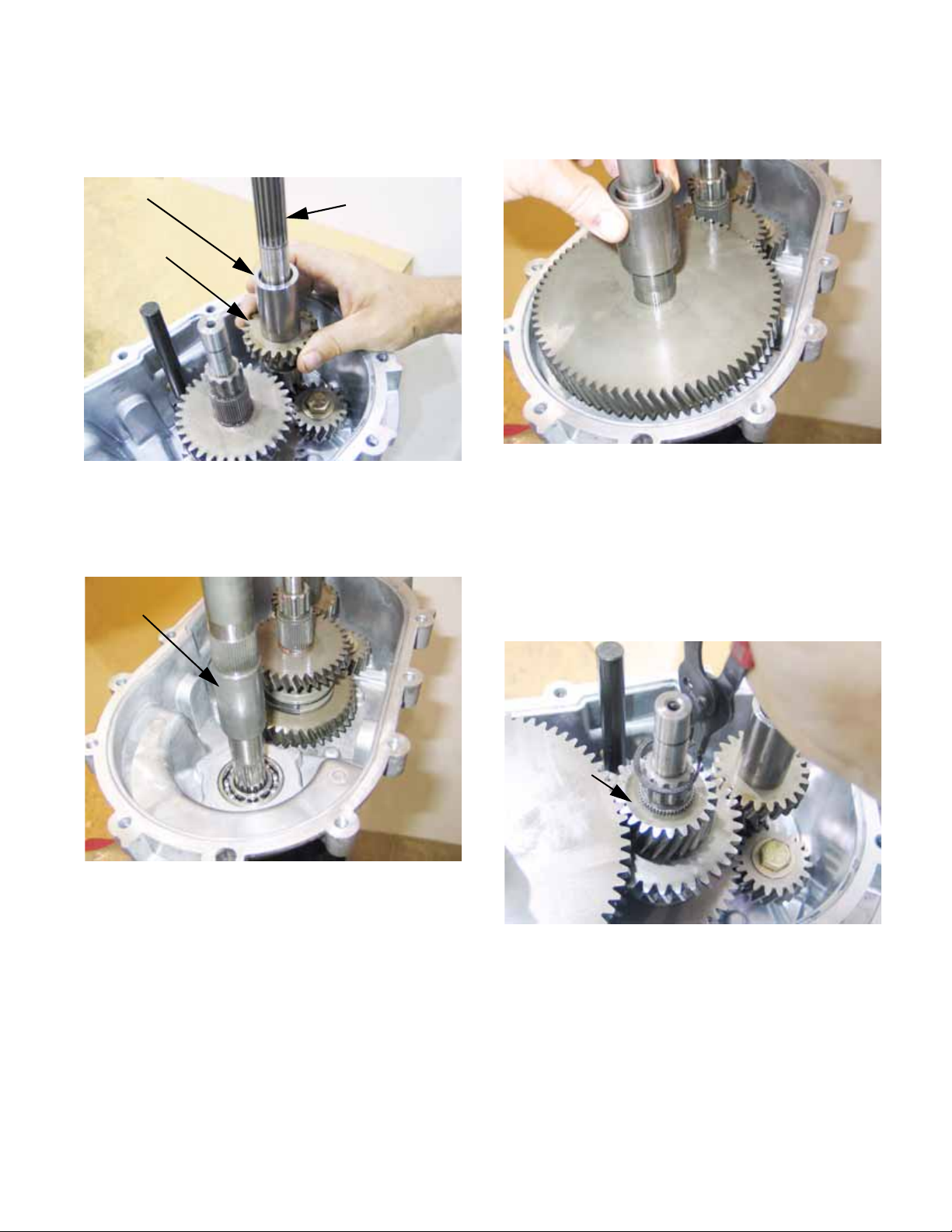
Chapter 2- Drive System: CVT and Transfer Case
3i. Install the 22-tooth for ward (high) gear and
spacer onto the input shaft.
See Figure 2.126.
Spacer
22-tooth
forward gear
Figure 2.126
3j. Insert the shorter , thicker end of the output
shaft through the third bearing in the right
side case half. See Figure 2.127.
Input shaft
3l. Install the spacer on the output shaft.
See Figure 2.128.
Figure 2.128
3m. Install the final pinion on the middle shaft.
The shoulder on the gear should face the
forward (high range) gear. The flat side
faces up.
Output shaft
Figure 2.127
3k. Install the bull gear on the output shaft. If
the bull gear or pinion gear have no t been
replaced, reinstall the gear in its original
orientation. Refer to the marks made on
removal.
3n. Install the snap ring that secures the final
pinion. Use a new snap ring.
See Figure 2.129.
Final pinion
(flat-side up)
Figure 2.129
3o. Apply a small amount of anti-seize com-
pound to the inside diameter of the lowrange shift collar.
53
3p. Position the shift collar on the low-range
shift shaft assembly.
3q. Apply a small amount of grease such as
Cub Cadet multi-purpose grease (P/N
737-3034) to the low range shift shaft.
Page 58

Chapter 2- Drive System: CVT and Transfer Case
3r. Insert the D-shaped end of the shift shaft
into the small bore that is closer to the
input shaft. The low range shift collar
would slip over the teeth on the middle
shaft. See Figure 2.130.
Figure 2.130
3s. Apply a small amount of grease such as
Cub Cadet multi-purpose grease (P/N
737-3034) to the inside diameter of the
low gear.
3t. Install the low gear on the middle shaft,
with the dog teeth facing the low range
shift collar.
3v. Install the small, .030” (.762mm) flat
washer on the middle shaft, against the
low pinion.
3w. Slip a new middle sha ft ret aining ri ng over
the small diameter portion of a 3/8” drive
3/8” socket. Push the ring down the
socket, onto the large diameter portion.
See Figure 2.132.
3/8” socket,
New hog ring
Figure 2.132
3x. Place the socket on top of the middle
shaft, and drive the ring onto the shaft
using a length of pipe or rigid tubing.
See Figure 2.133.
3/8” drive, deep
3u. Install the small, .030” (.762mm) flat
washer on the middle shaft, against the
low pinion. See Figure 2.131.
40-tooth
Low gear
Figure 2.131
short length
of pipe or
rigid conduit
Small .030”
flat washer
Hog ring
Socket
Middle shaft
Figure 2.133
NOTE: make sure the retaining ring is properly
seated in the groove on the middle shaft.
54
Page 59

Chapter 2- Drive System: CVT and Transfer Case
3y. Install the low pinion on the input shaft, fol-
lowed by the .060” (1.52mm) flat washer.
See Figure 2.134.
Input shaft
Flat washer
Low pinion
Figure 2.134
3z. Install the alignment dowels in the
untapped holes of the mating surface of
the right side case half. See Figure 2.135.
4. Checking and final assembly:
4a. Affix a dial indicator to the input shaft, so
that it reads against the case.
See Figure 2.136.
Checking input shaft end-play
Figure 2.136
4b. Work the input shaft up and down to get
and end-play measurement on the dial
indicator. End play should be less than
.009” (.23mm) without pre-loading the
input shaft bearing.
Bolt used
as a driver
Alignment
dowel
Figure 2.135
3aa. Lower the left side case half over the gear
set, so the sealing surfaces of the two
case halves meet.
3ab. Fasten the two case halves together using
four of the 5/16”-18 screws previously
removed. Tighten the screws “snug” but
they need not be torqued.
• If end play is greater than .009” add .010”
(.254mm) shim P/N: 736-0563 to correct.
4c. Affix the dial indicator to read the end-play
of the axle shaft. A mag-base is suitable.
See Figure 2.137.
Checking axle
shaft end-play
Figure 2.137
55
Page 60

Chapter 2- Drive System: CVT and Transfer Case
4d. Work the axle up and down to get and end-
play measurement on the dial indicator.
end play should be between .005”-.015”
(.127mm-.381mm).
• If axle end-play exceeds .015”, add .0 10 ”
(.254mm) shim P/N: 936-3104 to correct. In st all
the shim between the spacer and the bull gear.
4e. Position the forward-neutral-reverse shift
shaft (the one closer to the output shaft)
so that it extends 2” (5.1cm) from the surface of the case. See Figure 2.138.
Hole for forwardneutral-reverse
safety switch
F-N-R
Shift shaft
2”
Steel rule
Figure 2.138
4g. Position the low range shift shaft (the one
closer to the input shaft) so that it extends
2” (5.1cm) from the surface to the case.
See Figure 2.140.
Hole for low-range
safety switch
Low range
shift shaft
NOTE: The notch in the low range shift shaft will
be centered in the hole for the neutral safety
switch, indicating neutral position.
4h. Apply thread sealant to a neutral safety
2”
Figure 2.140
switch, and install the switch while holding
the shaft in neutral. See Figure 2.141.
Steel rule
NOTE: The notch in the shift yoke should be
centered in the hole for the F-N-R safety switch.
4f. Apply thread sealant to a neutral safety
switch, and install the switch in the F-N-R
switch hole, holding the shaft in neutral.
See Figure 2.139.
Safety switch installed
in F-N-R hole
Figure 2.139
Safety switch
installed in
low-range hole
Figure 2.141
4i. Tighten the neutral safety switches to a
torque of 380-480 in-lbs. (43-54 N-m).
56
Page 61

Chapter 2- Drive System: CVT and Transfer Case
4j. Test-spin the input shaft:
Neutral
•With both shift shafts in neutral, the output
shaft should not spin with any significant force
when the input shaft is turned. It may spin lightly
from internal friction.
Low Gear
• Push the low gear shift shaft in until the end of
the shaft extends 1-3/8” (3.5cm) from the case.
A click will be felt as it leaves neutral position.
• Rotate the input shaft. The output shaft should
rotate in the same direction as the input shaft at
roughly 1/10 the speed of the input shaft.
• Return the low gear shift shaft to neutral.
Reverse Gear
• Pull the forward-neutral-reverse shift shaft into
the reverse position. The end of the shaft
should extend 2-3/8” (6.03 cm) from the case.
A click will be felt as it leaves neutral position
• Rotate the input shaft. The output shaft should
spin in the opposite direction at less than 1/10
the speed of the input shaft.
• Return the low gear shift shaft to neutral.
Forward Gear (high)
• Push the forward-neutral-reverse shift shaft in,
past neutral. A click will be felt as it passesthrough the neutral position. Continue until the
shift shaft extends 1-9/16” (3.97cm) from the
case. This is forward gear.
4l. Insert the detent balls, followed by the
detent springs into the detent bores.
See Figure 2.142.
Detent ball
Detent spring
Figure 2.142
4m. Apply a thin layer of RTV sealant to the flat
portion of the detent plate. Fasten the
plate so that the bosses fit into the detent
bores, using the 1/4”-20 screw.
4n. Remove the screws that hold the case
together and remove the left case half.
4o. Apply a small bead of sealant to the seal-
ing surface, install the left side case half,
and secure them together using the
screws. See Figure 2.143.
• Rotate the input shaft. The output shaft should
spin in the same direction at roughly 1/5 the
speed of the input shaft.
• Return the low gear shift shaft to neutral.
4k. If any of the above checks does not hold
true, or if any unusual noises are heard
while performing the tests, identify and
correct the cause before continuing. It
may help to remove the left side case half
and carefully repeat the test to see what is
not working properly.
Properly sealed
case after splitting
NOTE:
bead groove
and
surface finish
Figure 2.143
4p. Tighten the screws to a torque of 200-260
in-lbs. (22.6-29.4 N-m), in an even pattern.
57
Page 62

Chapter 2- Drive System: CVT and Transfer Case
NOTE: Seal installation tips:
• The sealing surface on the shaft should be
inspected before assembly. Small scratches on
the sealing surface can be polished-out.
• Protect the lip of the seal using a seal protector
sleeve, obsolete microfiche, plastic, or cellophane tape.
• Lubricating the seal lips will help prevent damage.
• Do NOT use sealant between the seal and the
case.
• Drive seals straight down, by the outside edge,
using a suitable driver.
4s. Fasten the lug nut to the input shaft using a
5/16”-18 bolt. The tapered side of the lug
nut should face away from the input shaft.
4t. Slip the new hog ring over the lug nut, and
press it down using the flat side of the
heavy spacer previously removed from
the input shaft. See Figure 2.145.
Heavy spacer
(inverted)
Bolt to maintain
alignment
Modified lug nut
Hog ring
• Drive seals flush with the surface of the case
unless otherwise noted.
4q. Using a seal protector that spans the hog
ring groove, install the input shaft seal.
See Figure 2.144.
Seal protector
Input shaft seal
Figure 2.144
NOTE: The lip of the seal will
directly over the hog ring.
invert if it passes
Input shaft
Figure 2.145
4u. Press the hog ring home to its groove
using the spacer.
4v. Once the hog ring is seated, reverse the
spacer so that the recessed side goes
over the hog ring. See Figure 2.146.
Heavy spacer:
bevel and step face
hog ring
4r. Once the seal is fully seated, the hog ring
can be installed. It will be necessary to
make a special tool by modifying a lug nut
(P/N: 712-3050).
• Grind-down the peaks between each facet until
all the peak-to-peak measuremen ts are less
than 3/4” (1.9cm). Smooth the transition from the
tapered seat of the lug nut to the facets.
58
Figure 2.146
4w. Apply a small amount of thread locking
compound such as Loctite®
the four screws that hold the adaptor
housing to the case.
242 (blue) to
Page 63

Chapter 2- Drive System: CVT and Transfer Case
4x. Install the adaptor housing, using the ten-
sion pin to confirm proper indexing.
See Figure 2.147.
Adaptor
housing
Roll-pin
Roll pin bore
Figure 2.147
4y. Tighten the four screws that hold the ad ap-
tor housing to a torque of 200-260 in-lbs.
(22.6-29.4 N-m), in a “criss-cross” pattern.
NOTE: Refer to seal installation tips listed previously in this section.
4z. Install the pair of output shaft seals.
4aa. Install the pair of shift shaft seals.
4ab. Install the brake shaft seal. There is an
unusually large step in the brake shaft.
Substitute a short length of tubing for the
normal seal protector . Shipping caps from
hydraulic fittings and battery posts can be
cut to make suitable protector.
See Figure 2.148.
4ac. Install the magnetic drain plug in the bot-
tom of the transfer case. T ighten th e plug
to a torque of 220-280 in-lb. (25-32 N-m).
NOTE: If the sealing gasket needs replacement,
it can be ordered as part number 721-04174.
This part is not listed in the IPL.
4ad. If removed, install the vent. Tighten it 2-3
turns.
NOTE: Allow RTV sealant to cure according to
the sealant manufacturer’s instructions before
filling the case with gear lube.
4ae. Fill the case with 64 fl.oz. (1.9L) of 80W-90
Low Foam Oil (Cub Cadet P/N: 737-
04040). When full, gear lube will trickleout of the level plug hole.
4af. Install the level plug and tighten it to a
torque of 220-280 in-lb. (25-32 N-m).
4ag. Install the fill plug. Tighten it 2-3 turns.
NOTE: If the transfer case is to be filled after
installation, the fill plug and level plug may be
installed finger-tight. Label the transfer case
“EMPTY” in a prominent place until it is filled.
5. Install the shift arm assembly:
5a. Apply a small amount of thread locking
compound such as Loctite
the screws that hold the shift arm assembly to the case.
5b. Fasten the shift arm assembly to the case,
tightening the screws to a torque of 200260 in-lbs. (22.6-29.4 N-m).
See Figure 2.149.
Shift arm assembly
R
242 (blue) to
Seal driver
(PVC pipe)
Improvised
seal protector
Brake
shaft seal
Figure 2.148
Figure 2.149
59
Page 64

Chapter 2- Drive System: CVT and Transfer Case
5c. Install the low-gear shift arm.
See Figure 2.150.
Low range
shift arm
F-N-R shift arm
Figure 2.150
5d. Tighten the nut s on b oth pivo t bolt s of b oth
shift arms to a torque of 9 ft-lbs (13 Nm).
5e. Apply a small amount of thread locking
compound such as Loctite® 242 (blue) to
the threaded portion of the shoulder
screws that connect the shift shafts to the
shift arms.
5f. Install the shoulder screws, and tighten
them to a torque of 115 in-lb. (13 N-m).
See Figure 2.151.
6. Install the parking brake:
6a. Apply a small amount of thread locking
compound such as Loctite® 262 (red) to
the screws that hold the caliper bracket to
the case.
6b. Apply a small amount of ant-seize com-
pound to the brake shaft.
6c. Position the brake caliper and brake rotor
as one assembly, and secure them to the
case. See Figure 2.152.
Brake caliper bracket
Brake
caliper
NOTE: The flat side of the brake rotor faces out.
the shoulder goes toward the case.
Brake rotor
Figure 2.152
Figure 2.151
5g. Test the operation of the shift arms. It may
be necessary to rotate the input shaft for
internal gear alignment. Return both shift
arms to neutral when finished.
6d. Tighten th e screws to a torque of 115 in-lb.
(13N-m).
60
Page 65

Item ft-lbs N-m
Chapter 2- Drive System: CVT and Transfer Case
Reverse idler bolt
Neutral safety
switches
2
1
32-40 43-54
32-36 43-49
Detent plate screw 16-21 23
Case screws 16-21 23
Adaptor housing
screws
3
16-21 23
Drain and level plugs 18-23 25-32
Fill plug and vent snug snug
Shift arm bracket
3
16-21 23
Shift arm pivot bolt 9 13
Shift arm / shift pin
shoulder screws
3
Brake caliper bracket
screws
1
913
16-21 23
Brake caliper bolts
1
Apply a small amount of permanent thread locking
compound such as Loctite® 262 (red) to the screws
that hold the caliper bracket to the case.
2
Apply a small amount of thread sealant. PTFE-
based tape or liquid products are suitable.
3
Apply a small amount of “Service Removable” or
“Medium Strength” threadlocking compound such as
Loctite® 242 (blue) to the screws that hold the caliper
bracket to the case.
1
16-21 23
61
Page 66

Chapter 2- Drive System: CVT and Transfer Case
62
Page 67

Kohler Enclosed CVT Addendum
KOHLER ENCLOSED CVT ADDENDUM
DRIVE SYSTEM SERVICE: SAFETY AND TIPS
1. When working on the vehicle, set the parking
brake or block the wheels to keep it from rolling.
2. Place the transmission in neutral.
3. When working on any parts (like the CVT) that
rotate with the engine, disable the engine:
3a. Disconnect and ground the spark plug
wires on a gasoline engine.
3b. Remove the key from the key switch.
3c. Disconnect the ground cable from the neg-
ative terminal of the battery.
4. Unless a procedure specifically requires the
engine to be running, it should be turned-off for
all maintenance, adjustments, and repair.
5. There are some simple but specialized tools
needed to loosen the belt, remove the driving
pulley, and align the engine to the transfer case.
•A small screw can be used to spread the
sheaves of the driven element so that the belt
can be removed. Dimensions are in the text.
6. Standard tools that will be useful include:
Item Sizes
Combination wrench 1/2”, 9/16”, 30mm
Ratchet + sockets
5/16”, 1/2”, 9/16”,
5/8”, 10mm,
Torque wrench
22mm
Drill motor and bit 9/32”
Center-punch
Tor-X driver T-20, T-27
Alignment tool P/N: 707-04878
6mm-1.0 screw 2.9cm thread lgth.
Clutch puller P/N: 759-04111
Rivet gun
•A clutch puller (part number: 759-04111) is
needed to pull the driving element off of the
tapered crankshaft.
•Use the alignment tool (part number: 707-
04878) to check spacing and alignment between
the crankshaft and the transfer case input shaft.
63
Page 68
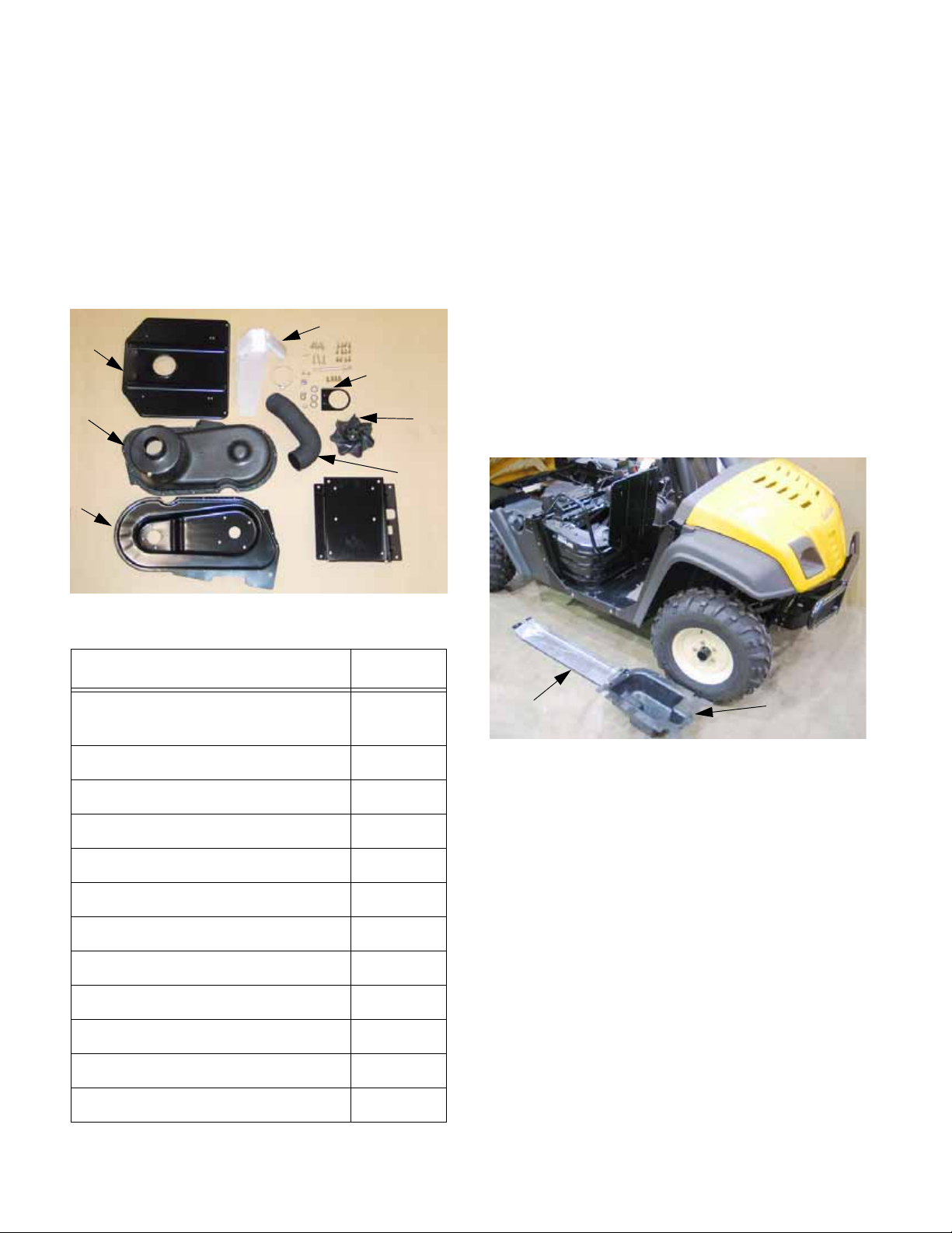
Kohler Enclosed CVT Addendum
CONVERSION INSTRUCTIONS: ENCLOSED CVT
1. PREPARATION
1a. Review and understand these instructions
before starting to work on the vehicle.
1b. Collect all necessary tools.
1c. Lay-out the contents of the CVT enclosure
kit. Make sure all the parts are present
and identified. See Figure 2a.1.
Seat
plate
Cover
Back
plate
Heat shield
Tub e bkt.
Fan
Tube
2. ACCESS
2a. Lift the load box (bed).
2b. Slide the driver’s seat all the way back on
its tracks.
2c. Tilt the seats forward. Secure the driver’s
seat in the tilted position using a shock
cord.
2d. Release the Camlok fasteners that secure
the parcel bin under the passenger seat,
and remove the parcel bin.
2e. Release the camlok fasteners that secure
the engine cover, and remove the cover.
2f. Unbolt the passenger’s seat mounting
bracket from the seat plate using a pair of
1/2” wrenches. See Figure 2a.2.
Seat bracket
Figure 2a.1
Description Qty.
Mounting stud: driven pulley
and fan
Washer 1
Castle nut, 1/2”-20 1
Washer, fan 1
Cotter pin, 3/32” x 1” 1
Back plate-eng. screw 4
Back plate-trans screw 4
Heat shield screw 3
Heat shield spacer 3
Engine
1
cover
Figure 2a.2
2g. Remove the grab handle and seat plate
assembly from the vehicle using a pair of
1/2” wrenches.
Parcel bin
Cover screw 12
Bracket mount screw 2
CVT Spacer washers 3
64
Page 69
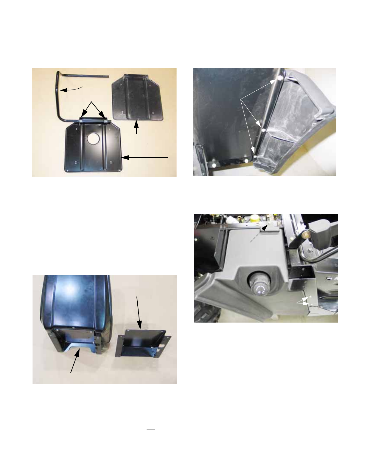
Kohler Enclosed CVT Addendum
2h. Remove the original seat plate from the
grab handle, and replace it with the seat
plate from the kit. See Figure 2a.3.
Grab bar
Flange brgs.
Old seat plate
New seat plate
Figure 2a.3
NOTE: The flange bearings that the seat pivots
on fit through the holes in the seat plate with the
shoulders to the outside, so that the bolts holding the grab handle to the vehicle trap the bearings in position.
2j. Remove the three screws that hold the
right rear fender to the splash shield using
a 5/16” wrench. See Figure 2a.5.
Fender to
splash shield
screws
Figure 2a.5
2k. Remove the remaining fasteners that hold
the fender to the vehicle: See Figure 2a.6.
2i. Replace the original seat bracket with the
seat bracket contained in the kit. Position
the rear set of seat bracket mounting bolts
in the bracket before bolting the seat to
the bracket. See Figure 2a.4.
Old seat
bracket
New seat bracket
Figure 2a.4
NOTE: The opening in the front of the new seat
bracket is vital. This opening allows cooling air
to enter the CVT enclosure. If the supply of
cooling air is restricted, the CVT belt will
heat and fail.
over-
Top screw
Front edge
screws
Figure 2a.6
• Remove the two screws that hold the front edge
of the fender to the upright that the rear tube of
the OPS mounts to using a 5/16” wrench.
• Remove the single screw that holds the top of
the fender to the frame using a 1/2” wrench.
• Remove the gas cap.
65
Page 70

Kohler Enclosed CVT Addendum
2l. Remove the fender: See Figure 2a.7.
Figure 2a.7
• Pull the fender out slightly at the top to provide
freedom of movement around the fuel filler neck.
• Lift the fender up at the back to pull the front
edge clear of the channel that it locks into.
• Pull the fender clear of the vehicle.
• Replace the gas cap.
2m. Remove the right rear splash shield:
See Figure 2a.8.
3. BELT REMOVAL
3a. T o remove the belt, a 6mm/1.0 screw with
a minimum thread length of 1.15" (2.9cm)
will be required. See Figure 2a.9.
1.15” (2.9cm)
thread length
Figure 2a.9
NOTE: A 6mm screw with a thread pitch of 1.0
may be purchased locally. The minimum thread
length needed is longer than the threads of a
standard screw of this size. It will be necessary
to cut threads further up the shank of the screw
using a thread-cutting die, or neck-down the
shank of the bolt on a grinding wheel.
Figure 2a.8
• Remove the 6 screws connecting the splash
shield to the frame using a 1/2” wrench.
• Support the splash shield, and remove the final
screw using a 5/16” wrench.
• Lift the splash shield off of the vehicle.
3b. There are 4 holes in the face of th e d riven
element. The middle hole of the closest
set of three is threaded. The other three
are not threaded. See Figure 2a.10.
Tapped hole
Figure 2a.10
66
Page 71
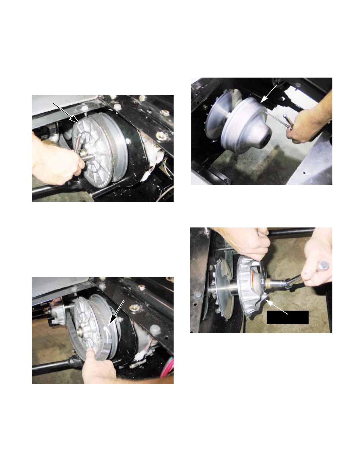
Kohler Enclosed CVT Addendum
3c. Lubricate the screw with a small amount of
grease or motor oil, then thread the screw
into the tapped hole in the outer sheave of
the driven element.
The end of the screw will press against
the inner half of the sheave, spreading the
two apart. See Figure 2a.11.
Driven pulley
Install screw
to spread sheaves
Figure 2a.11
3d. Mark the direction of rotation on the belt.
It must be reinstalled so that it rotates in
the same direction.
4. REMOVE THE CVT PULLEYS
4a. Remove the three screws holding the
cover in place using a T- 20 driver, then
remove the cover. See Figure 2a.13.
Cover: driving pulley
Figure 2a.13
4b. Hold the large nut with a 30mm wrench
while loosening the crankshaft bolt with a
5/8” wrench. See Figure 2a.14.
3e. As the sheaves are spread, the tension on
the belt will be relieved, and the belt can
be rolled-off of the driven element (pulley).
See Figure 2a.12.
Arrow to maintain
orientation
Figure 2a.12
Driving pulley
Figure 2a.14
67
Page 72
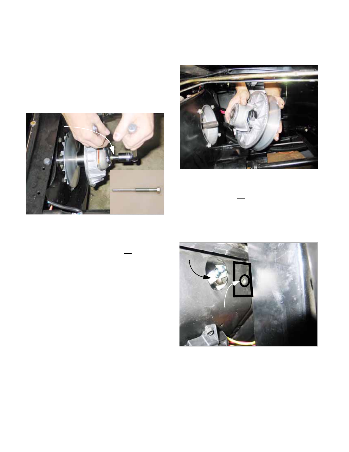
Kohler Enclosed CVT Addendum
4c. Withdraw the bolt, washers, and shoulder
spacer.
4d. Install the clutch removal tool by threading
it into the clutch (driving pulley), pressing
against the crankshaft.
4e. Hold the pulley with a 30mm wrench, and
turn the tool using a 22mm wrench. This
will force the driving pulley (clutch) off of
the crankshaft. See Figure 2a.15.
Clutch tool
installed
Inset: Clutch tool
P/N: 759-04111
4i. Slide the driven pulley off of the splined
transfer case input shaft.
See Figure 2a.16.
Driven pulley removal
Figure 2a.16
CAUTION: Do not pry on the outer edge of the
driven pulley. It will
bend, ruining the pulley.
Figure 2a.15
CAUTION: There is a tapered fit between the
driving pulley and the crankshaft. Prying on the
perimeter of the driving element will
4f. Place the gear selector in H position, and
set the parking brake.
4g. Loosen the bolt holding the driven pulley
to the input shaft using a 9/16” wrench.
4h. Remove the bolt and washers.
break it.
5. Change back plate
5a. Disconnect the heat shield from the engine
cooling shroud using a 10mm wrench.
See Figure 2a.17.
Spark plug
Heat shield
mounting point
Figure 2a.17
5b. Loosen all the screws that hold the back
plate to the engine using a 9/16” wrench.
Remove all but one.
68
Page 73
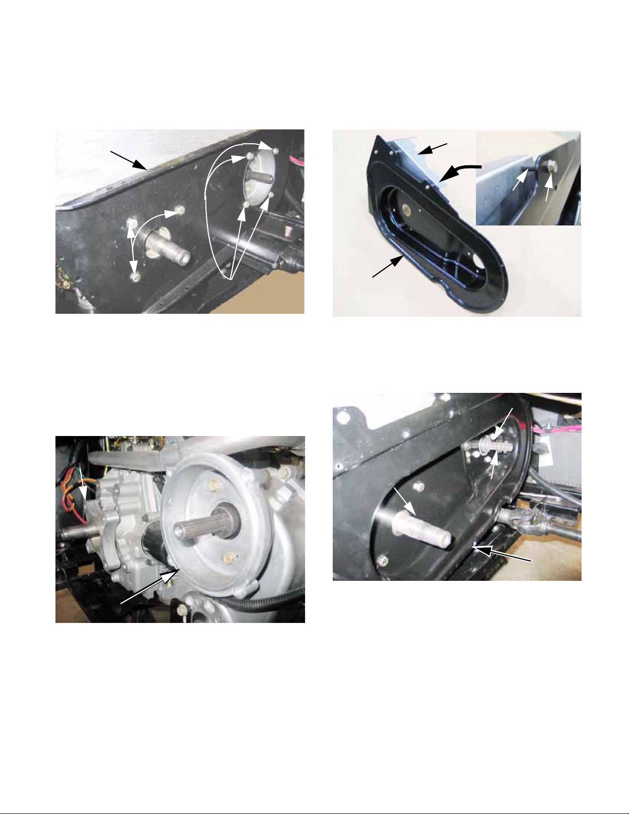
Kohler Enclosed CVT Addendum
5c. Loosen all the screws that hold the back
plate to the transfer case using a 1/2”
wrench. Remove all but one.
See Figure 2a.18.
Original back plate
Screws
mounting
back plate to
engine
Screws mounting
back plate to
transfer case
Figure 2a.18
5d. Remove the final two screws and carefully
lift the back plate and heat shield out of
the vehicle.
5h. Attach the heat shield to the new back
plate using the 1/4-20 screws and spacers. Tighten them using a 5/16” wrench.
See Figure 2a.20.
Heat
shield
New back plate
Figure 2a.20
5i. Position the new back plate, connecting
the engine to the transfer case.
See Figure 2a.21.
Inset: mounting
detail
Spacer
Screw
5e. Remove the adaptor from the transfer
case using a 1/2” wrench.
See Figure 2a.19.
Engine
spacer
Transfer case
adaptor
Figure 2a.19
5f. Remove the spacer from the engine. It
was held to the engine by the same
screws that held the back plate.
5g. Rivet the two parts of the heat shield
together.
Transfer case
input shaft
Engine
crankshaft
NOTE: If the new back plate does not align properly with the mounting holes, loosen the transfer
case mounting brackets from the engine-transfer
case tray, and adjust the position of the transfer
case. DO NOT loosen the screws that hold the
brackets to the transfer case.
5j. Apply releasable thread-locking compound
such as Loctite 242® (blue) to the (4) 5/
16-18 screws and the (4) 3/8-16 screws
contained in the kit. Install the screws and
gradually tighten all of them.
Spacer washers
New back plate
in position
Figure 2a.21
69
Page 74

Kohler Enclosed CVT Addendum
• Tighten the 5/16-18 screws to a torque of 18-22
ft-lbs. (24-30 N-m).
• Tighten the 3/8-16 screws to a tor que of 22-25 f tlbs. (30-34 N-m).
5k. Once the back plate is secured to the
engine and transfer case, check to see
that: The heat shield does not fowl the
engine governor. See Figure 2a.22.
Heat shield
Figure 2a.22
6. CVT Installation
6a. Prepare the CVT for installation:
• Clean the shafts and the surrounding area
before installing the CVT.
• Confirm the presence of the .060” (1.5mm)
spacer on the shaft between the driven element
and the transfer case housing.
• A small amount of anti-seize compound may be
used on the splined joint between the input shaft
of the transfer case and the driven element.
• The tapered joint between the driven element
and the crankshaft may be lubricated with a
small amount of multi-purpose grease (Cub
Cadet P/N: 737-3034).
• Apply a small amount of thread locking compound such as Loctite® 262 (red) to the stud
that will secure the driving pulley.
NOTE: The screw that holds the driven pulley to
the input shaft of the transfer case will be
reused.
The screw that held the driving pulley to the
engine crankshaft will be replaced with the double-ended stud.
• Once the back plate is secured to the engine
and transfer case, check to see that the wires
near the starter motor are securely routed a safe
distance from the heat shield and any pinch
points. See Figure 2a.23.
Wires against
heat shield
Figure 2a.23
6b. Fasten the driving pulley to the cran ksha ft
using the bolt, washer, and shoulder
spacer previously removed on the doubleended stud. Tighten it to a torque of 3536 ft-lbs.(43-49 N-m). See Figure 2a.24.
Figure 2a.24
6c. Secure the driven pulley to the input shaft
using the bolt, washer, and shoulder
spacer previously removed.
70
Page 75

Kohler Enclosed CVT Addendum
6d. Check the alignment of the two pulleys:
Place the alignment tool over the hub of
the driven pulley so that it lays flat against
the front surface of it.
The furthest corner of the thick end of the
tool should meet-up with the inner lip of
the fixed sheave on the driving pulley
See Figure 2a.25.
Shims behind
NOTE: The outer sheave of the driving pulley
moves inward to clamp the belt as engine RPMs
increase.
6e. Adjust the number of shims behind the
6f. Once alignment is correct, install the
driven pulley
Critical
corner
Figure 2a.25
driven pulley to achieve correct alignment.
Use the three .800” (2 cm) I.D. flat washers that are included in the kit, if necessary.
driven pulley screw with thread locking
compound such as Loctite®
and tighten it to 32-36 ft-lb. (43-49 N-m).
262 (red),
6g. Install the cooling fan on the driving pulley,
securing it with the flat washer and castle
nut. See Figure 2a.26.
Fan
Washer
Castle nut
Alignment
tool
Figure 2a.26
6h. Tighten the nut to a torque of 22-25 ft-lbs.
(30-34 N-m), then secure it using the cotter pin.
6i. Inspect the drive belt. If it is worn to less
than 1.20” (30.5mm) across the flat back
surface of the belt, or if is shows signs of
burning or checking, replace it with a new
belt.
6j. Roll the drive belt back onto the pulleys.
Refer to the marks made before the belt
was removed, to confirm that the direction
of rotation has not been changed.
See Figure 2a.27.
71
Figure 2a.27
Page 76

Kohler Enclosed CVT Addendum
6k. Remove the screw that was used to
spread the sheaves of the driven pulley.
6l. Place the gear selector in neutral.
6m. Re-connect the spark plug leads to the
spark plugs.
6n. Re-connect the negative battery cable.
6o. Confirm that the drive belt area is clear,
and that no unsafe conditions will arise
from starting the engine.
6p. Start the engine briefly and confirm tha t
the CVT operates properly throughout the
engine RPM range, before installing the
CVT cover.
• The driven pulley should not rotate when the
engine is at idle speed.
• If the driven pulley does rotate at idle speed:
Re-check the spacing and alignment of the pulleys.
Confirm that the driving pulley is returning all the
way to rest position at idle.
7. FINAL ASSEMBLY
7a. Install the drain plug in the CVT cover, and
carefully tighten it until snug, using a 1/2”
wrench.
7c. Rotate the CVT cover down into position.
7d. Fasten the CVT cover to the back plate
using the (12) 1/4-20 self tapping screws.
See Figure 2a.29.
CVT cover
fastened to
back plate
Figure 2a.29
7e. Reinstall the right rear splash shield and
fender.
7f. Reinstall the grab handle with the new
seat plate. See Figure 2a.30.
7b. Slip the CVT cover in through the opening
in the passenger side of the seat box.
See Figure 2a.28.
Position the CVT cover
Figure 2a.28
Flange bushings
Spacers
(secured with
tape to ease
mounting)
Figure 2a.30
7g. Use the opening in the new seat plate to
locate the tube support bracket. The
openings in the seat plate and the bracket
should be concentric.
7h. Mark the points to drill mounting holes for
the tube support bracket.
72
Page 77

7i. Center-punch and drill the two mounting
holes in the seat box using a 9/32” (7mm)
drill bit.
7j. Mount the bracket beneath the front lip of
the seat box. Tighten the two 1/4-14
screws using a T-27 driver.
See Figure 2a.31.
Opening in bottom
of seat plate
Tube bracket
Kohler Enclosed CVT Addendum
Figure 2a.31
7k. Install the intake tube b etween the bracket
and the spigot on the front of the CVT
cover. Secure it with the hose clamp.
See Figure 2a.32.
Intake tube installed
Figure 2a.32
7l. Reinstall the engine cover and parcel bin.
7m. Lower the work-box and seats.
7n. Test-drive the vehicle in a safe place to
confirm that it operates properly before
returning it to service.
73
Page 78

Kohler Enclosed CVT Addendum
74
Page 79

Caterpillar Enclosed CVT Addendum
CATERPILLAR ENCLOSED CVT ADDENDUM
DRIVE SYSTEM SERVICE: SAFETY AND TIPS
1. When working on the vehicle, set the parking
brake or block the wheels to keep it from rolling.
2. Place the transmission in neutral.
3. When working on any parts (like the CVT) that
rotate with the engine, disable the engine:
3a. Disconnect the fuel solenoid.
3b. Remove the key from the key switch.
3c. Disconnect the ground cable from the neg-
ative terminal of the battery.
4. Unless a procedure specifically requires the
engine to be running, it should be turned-off for
all maintenance, adjustments, and repair.
5. There are some simple but specialized tools
needed to loosen the belt, remove the driving
pulley, and align the pulleys.
•A small screw can be used to spread the
sheaves of the driven element so that the belt
can be removed. Dimensions are in the text.
•A clutch puller (part number: 759-04111) is
needed to pull the driving element off of the
tapered crankshaft.
6. Standard tools that will be useful include:
Item Sizes
Combination wrench 7/16”, 1/2”, 9/16”,
30mm
Ratchet + sockets
5/16”, 7/16”, 1/2”,
9/16”, 5/8”,
Torque wrench
10mm, 22mm
Drill motor and bit 9/32”
Center punch, ham-
mer
Tor-X driver T-20, T-27
Alignment tool P/N: 707-04878
6mm-1.0 screw 2.9cm thread lgth.
Clutch puller P/N: 759-04111
•Use the alignment tool (part number: 707-
04878) to check spacing and alignment between
the crankshaft and the transfer case input shaft.
75
Page 80

Caterpillar Enclosed CVT Addendum
CONVERSION INSTRUCTIONS: ENCLOSED CVT
1. PREPARATION
1a. Review and understand these instructions
before starting to work on the vehicle.
1b. Collect all necessary tools.
1c. Lay-out the contents of the CVT enclosure
kit. Make sure all the parts are present
and identified. See Figure 2b.1.
Intake tube
New back plate
CVT cover
Seat
bracket
Seat plate
Tube
bracket
Fan
2. ACCESS
2a. Lift the load box (bed).
2b. Slide the driver’s seat all the way back on
its tracks.
2c. Tilt the seats forward. Secure the driver’s
seat in the tilted position using a shock
cord.
2d. Release the Camlok fasteners that secure
the parcel bin under the passenger seat,
and remove the parcel bin.
2e. Release the camlok fasteners that secure
the engine cover, and remove the cover.
2f. Unbolt the passenger’s seat mounting
bracket from the seat plate using a pair of
1/2” wrenches. Remove the seat and
bracket. See Figure 2b.2.
Seat plate
Figure 2b.1
Description Qty.
Mounting stud: driven pulley
1
and fan
Washer 1
Castle nut, 1/2”-20 1
Washer, fan 1
Cotter pin, 3/32” x 1” 1
Back plate-eng. screw 5
Back plate-trans screw 4
Cover screw 12
Bracket mount screw 2
CVT Spacer washers 3
Seat mounting bracket
Figure 2b.2
NOTE: It is not necessary to disconnect any fuel
lines. The fuel pump and filter will be moved to
provide room for the CVT cover to fit into the
area below the seat box.
76
Page 81

Caterpillar Enclosed CVT Addendum
3. Unbolt the fuel filter bracket from the vehicle
using a 1/2” wrench. See Figure 2b.3.
Fuel filter bracket
Figure 2b.3
3a. With the fuel filter and bracket out of the
way, the grab bar and seat plate can be
removed using a pair of 1/2” wrenches.
See Figure 2b.4.
3b. Remove the original seat plate from the
grab handle, and replace it with the seat
plate from the kit. See Figure 2b.5.
Grab bar
Flange bearings
Old seat plate
New seat plate
Figure 2b.5
NOTE: The flange bearings that the seat pivots
on fit through the holes in the seat plate with the
shoulders to the outside. The bolts holding the
grab handle to the vehicle trap the bearings in
position.
Grab handle
Figure 2b.4
3c. Replace the original seat bracket with the
seat bracket contained in the kit. Position
the rear set of seat bracket mounting bolts
in the bracket before bolting the seat to
the bracket. See Figure 2b.6.
Old seat bracket
New seat bracket
Figure 2b.6
NOTE: The opening in the front of the new seat
bracket is vital. This opening allows cooling air
to enter the CVT enclosure. If the supply of
cooling air is restricted, the CVT belt will
heat and fail.
over-
77
Page 82
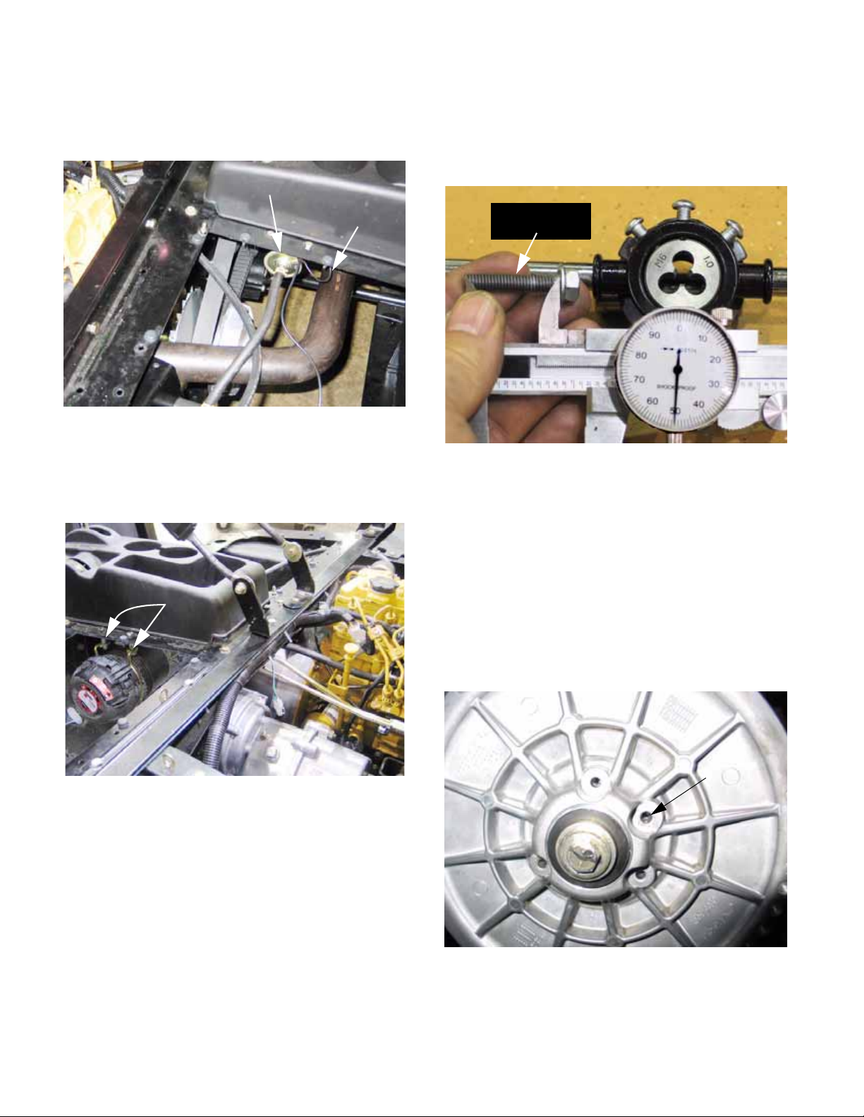
Caterpillar Enclosed CVT Addendum
3d. Unbolt the electric fuel pump from the con-
sole-cup holder support using a pair of 7/
16” wrenches. See Figure 2b.7.
Fuel pump
Ground wire
Figure 2b.7
3e. Unbolt the air filter bracket from the con-
sole-cup holder support using a pair of 1/
2” wrenches. See Figure 2b.8.
Air filter bracket
4. BELT REMOVAL
4a. T o remove the belt, a 6mm/1.0 screw with
a minimum thread length of 1.15" (2.9cm)
will be required. See Figure 2b.9.
1.15” (2.9cm)
thread length
Figure 2b.9
NOTE: A 6mm screw with a thread pitch of 1.0
may be purchased locally. The minimum thread
length needed is longer than the threads of a
standard screw of this size. It will be necessary
to cut threads further up the shank of the screw
using a thread-cutting die, or neck-down the
shank of the bolt on a grinding wheel.
Figure 2b.8
3f. Loosen the hose clamp that holds the tube
f r o m t h e a i r f i l t e r t o t h e e ng in e a ir in ta ke .
Remove the tube from the engine and seal
the openings with tape or clean shop towels
to prevent dirt from getting into the engine.
Remove the filter and hose from the vehicle.
NOTE: If both openings are not sealed, dirt can
enter the engine directly or by contam inating the
air intake tube, down-stream of the filter.
4b. There are 4 holes in the face of th e d riven
element. The middle hole of the closest
set of three is threaded. The other three
are not threaded. See Figure 2b.10.
Tapped hole
Figure 2b.10
78
Page 83
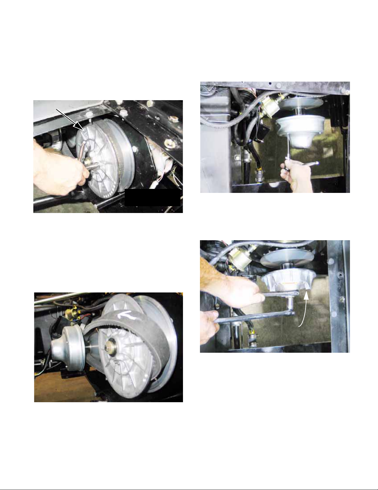
Caterpillar Enclosed CVT Addendum
4c. Lubricate the screw with a small amount of
grease or motor oil, then thread the screw
into the tapped hole in the outer sheave of
the driven element.
The end of the screw will press against
the inner half of the sheave, spreading the
two apart. See Figure 2b.11.
Driven pulley
Install screw
to spread sheaves
Figure 2b.11
4d. Mark the direction of rotation on the belt.
It must be reinstalled so that it rotates in
the same direction.
5. REMOVE THE CVT PULLEYS
5a. Remove the three screws holding the
cover in place using a T- 20 driver, then
remove the cover. See Figure 2b.13.
Figure 2b.13
5b. Hold the large nut with a 30mm wrench
while loosening the crankshaft bolt with a
5/8” wrench. See Figure 2b.14.
4e. As the sheaves are spread, the tension on
the belt will be relieved, and the belt can
be rolled-off of the driven element (pulley).
See Figure 2b.12.
Figure 2b.12
Driving pulley
Figure 2b.14
79
Page 84
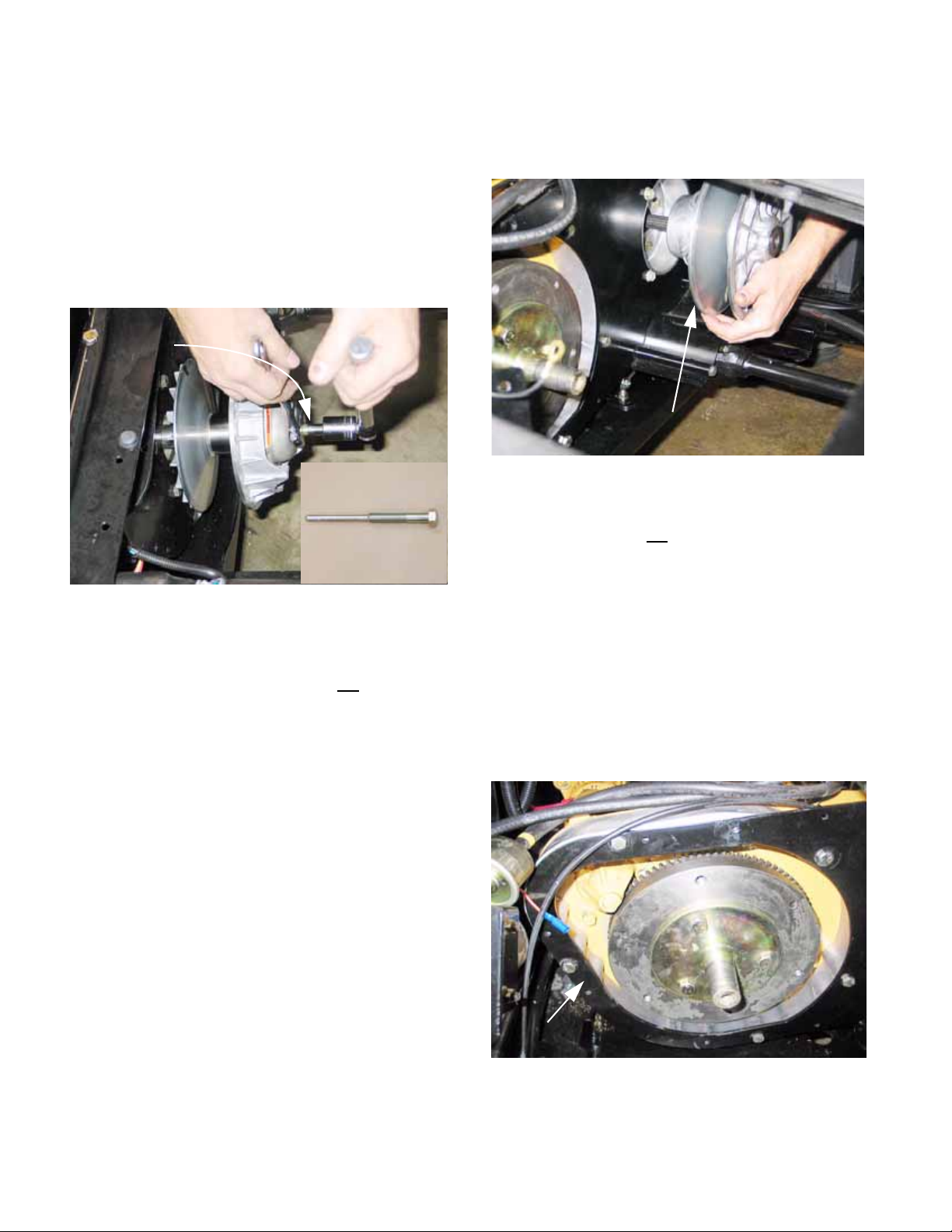
Caterpillar Enclosed CVT Addendum
5c. Withdraw the bolt, washers, and shoulder
spacer.
5d. Install the clutch removal tool by threading
it into the clutch (driving pulley), pressing
against the crankshaft.
5e. Hold the pulley with a 30mm wrench, and
turn the tool using a 22mm wrench. This
will force the driving pulley (clutch) off of
the crankshaft. See Figure 2b.15.
Clutch tool
installed
Inset: Clutch tool
P/N: 759-04111
5i. Slide the driven pulley off of the splined
transfer case input shaft.
See Figure 2b.16.
Driven pulley
Figure 2b.16
CAUTION: Do not pry on the outer edge of the
driven pulley. It will
bend, ruining the pulley.
Figure 2b.15
CAUTION: There is a tapered fit between the
driving pulley and the crankshaft. Prying on the
perimeter of the driving element will
5f. Place the gear selector in H position, and
set the parking brake.
5g. Loosen the bolt holding the driven pulley
to the input shaft using a 9/16” wrench.
5h. Remove the bolt and washers.
break it.
6. Change back plate
6a. Remove the two screws that hold the
starter motor to the engine plate using a
14mm wrench. This will improve access
to the nuts holding the engine pate and
adaptor.
6b. Loosen the five bolts that hold the back
plate to the engine plate using a pair of 1/
2” wrenches. Remove all but one.
See Figure 2b.17.
Back plate
Figure 2b.17
80
Page 85
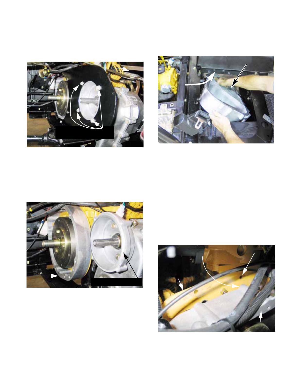
Caterpillar Enclosed CVT Addendum
6c. Loosen the four screws that hold the back
plate to the transfer case adaptor using a
1/2” wrench. Remove all but one.
See Figure 2b.18.
Screws holding back plate
to transfer case adaptor
Figure 2b.18
6d. Remove the final two screws and carefully
lift the back plate out of the vehicle.
6e. Remove the adaptor from the transfer
case using a 1/2” wrench.
See Figure 2b.19.
6g. Position the new aluminum back plate,
connecting the engine to the transfer
case. See Figure 2b.20.
New back plate
Figure 2b.20
NOTE: If the new back plate does not align prop-
erly with the mounting holes, loosen the transfer
case mounting brackets from the engine-transfer
case tray, and adjust the position of the transfer
case. DO NOT loosen the screws that hold the
brackets to the transfer case.
6h. Apply releasable thread-locking com-
pound such as Loctite 242® (blue) to the
(9) 5/16-18 screws contained in the kit.
Engine
adaptor
6f. Remove the spacer from the engine.
It was held to the engine by the same
screws that held the back plate.
Transfer case adaptor
Figure 2b.19
6i. Secure the new back plate to the engine
plate. Tighten the screws nearest the
alignment dowels just far enough to
engage the dowels. See Figure 2b.21.
Dowel pin
Engine plate
Figure 2b.21
Dowel hole
New back plate
81
Page 86
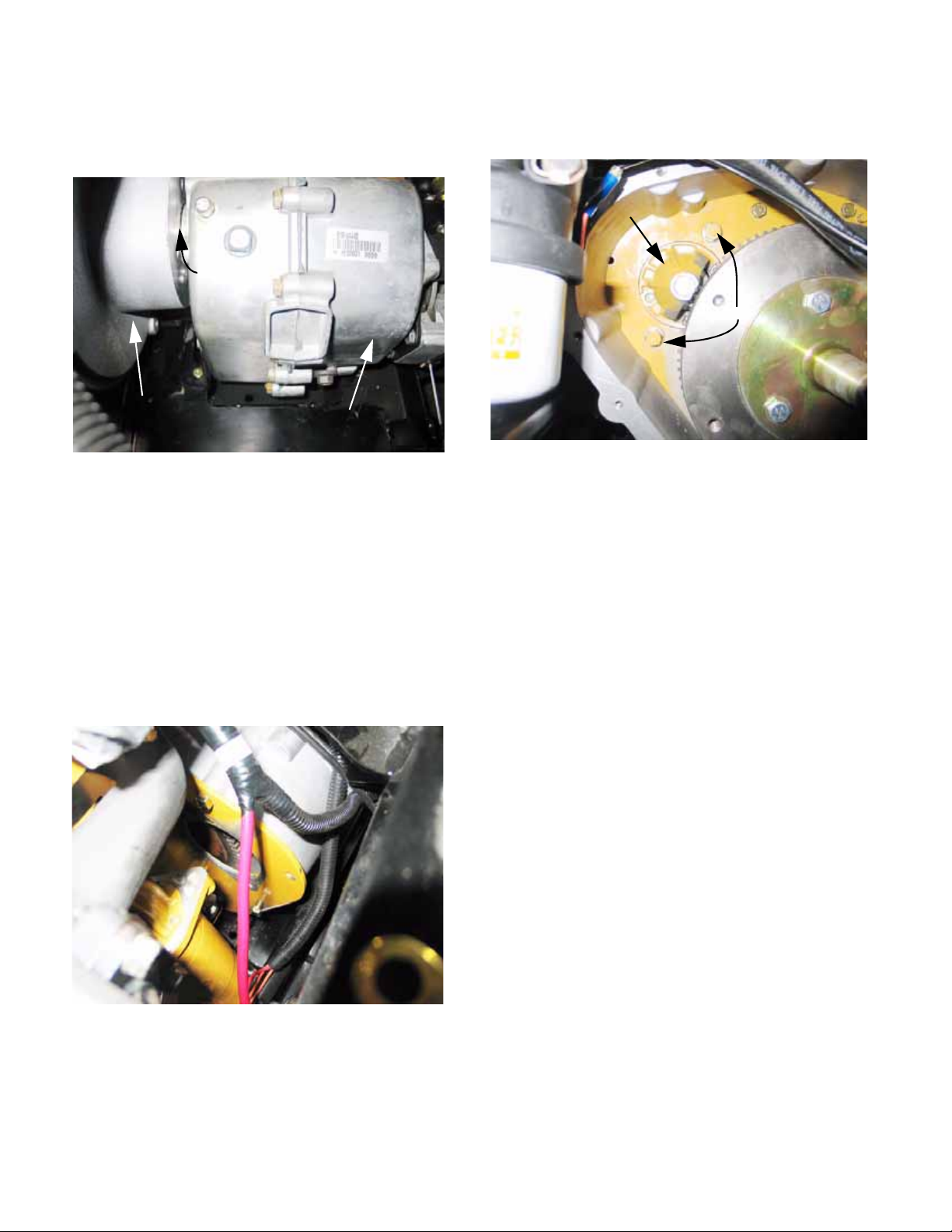
Caterpillar Enclosed CVT Addendum
6j. Seat the opening at the transfer case end
of the back plate over the boss that surrounds the input shaft. See Figure 2b.22.
Mounting boss
Back plate
Transfer case
Figure 2b.22
• If the opening in the back plate sill not align with
the boss on the transfer case, DO NOT attempt
to draw the two together by tightening the
screws.
• If necessary, loosen the screws that hold the
transfer case brackets to the engine and transfer
case tray using a pair of 1/2” wrenches.
6k. Once the back plate is properly aligned on
engine and transfer case, tighten all the
screws. See Figure 2b.23.
6l. Re-mount the starter motor.
See Figure 2b.24.
Starter motor
Screws
Figure 2b.24
• Apply releasable thread-locking compound su ch
as Loctite 242® (blue) to the screws.
• Install the screws and lock-washers that hold the
starter to the engine plate, tightening the screws
to a torque of 22-25 ft-lbs (30-34 N-m).
• Check electrical connections and insulating
boots on the starter motor and solenoid.
7. CVT Installation
7a. Prepare the CVT for installation:
• Clean the shafts and the surrounding area
before installing the CVT.
Figure 2b.23
82
Page 87
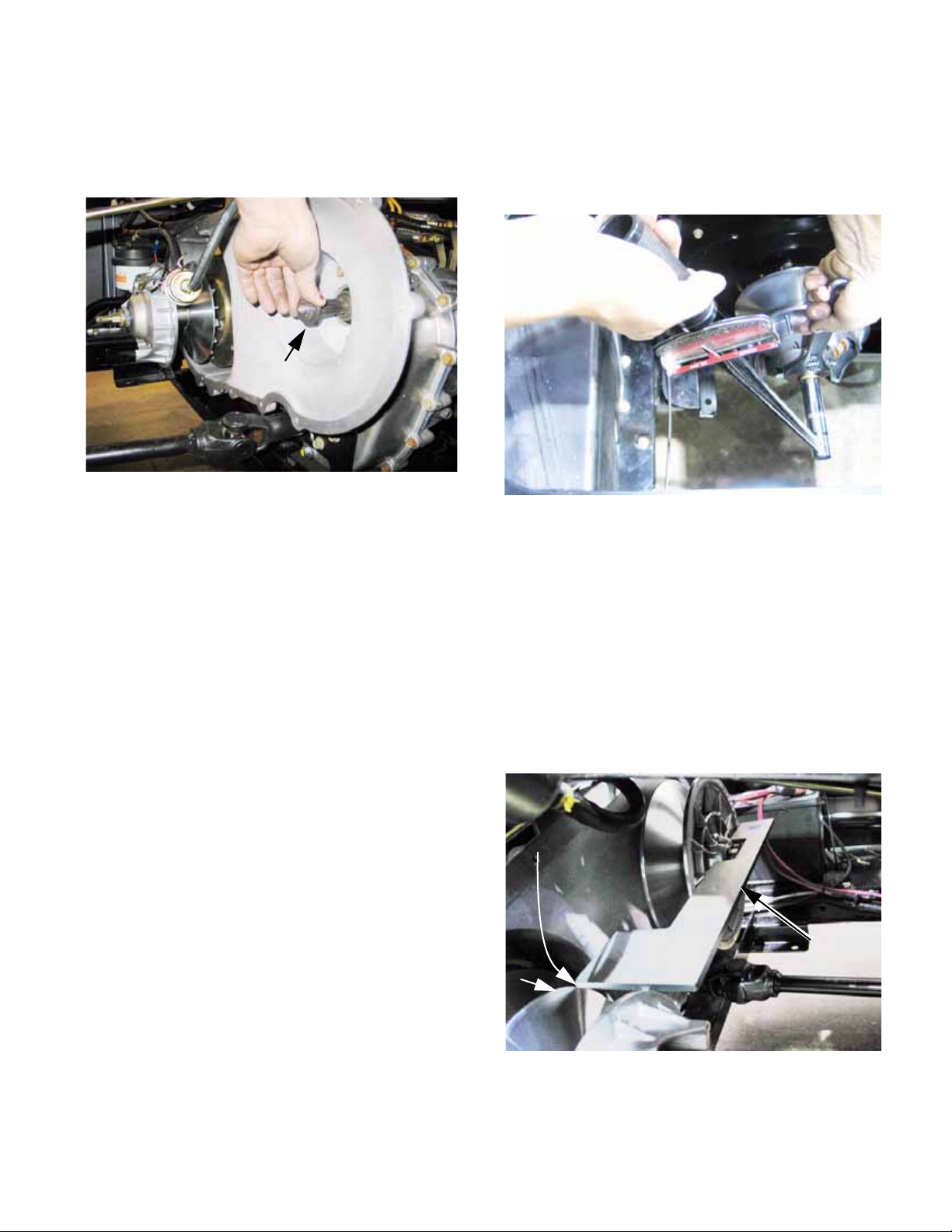
Caterpillar Enclosed CVT Addendum
• Confirm the presence of four .030” (.75mm)
spacers on the shaft between the dr iven element
and the transfer case housing.
See Figure 2b.25.
Spacers
Figure 2b.25
• A small amount of anti-seize compound may be
used on the splined joint between the input shaft
of the transfer case and the driven element.
• The tapered joint between the driven element
and the crankshaft may be lubricated with a
small amount of multi-purpose grease (Cub
Cadet P/N: 737-3034).
• Apply a small amount of thread locking compound such as Loctite® 262 (red) to the stud
that will secure the driving pulley.
NOTE: The screw that holds the driven pulley to
the input shaft of the transfer case will be
reused.
The screw that held the driving pulley to the
engine crankshaft will be replaced with the double-ended stud.
7b. Fasten the driving pulley to the cran ksha ft
using the, washer and shoulder spacer
previously removed on the double-ended
stud. Tighten it to a torque of 35-36 ftlbs.(43-49 N-m). See Figure 2b.26.
Figure 2b.26
7c. Secure the driven pulley to the input shaft
using the bolt, washer, and shoulder
spacer previously removed.
7d. Check the alignment of the two pulleys:
Place the alignment tool over the hub of
the driven pulley so that it lays flat against
the front surface of it.
The furthest corner of the thick end of the
tool should meet-up with the inner lip of
the fixed sheave on the driving pulley
See Figure 2b.27.
Critical corner
83
Alignment
tool
Inside
lip
Figure 2b.27
Page 88
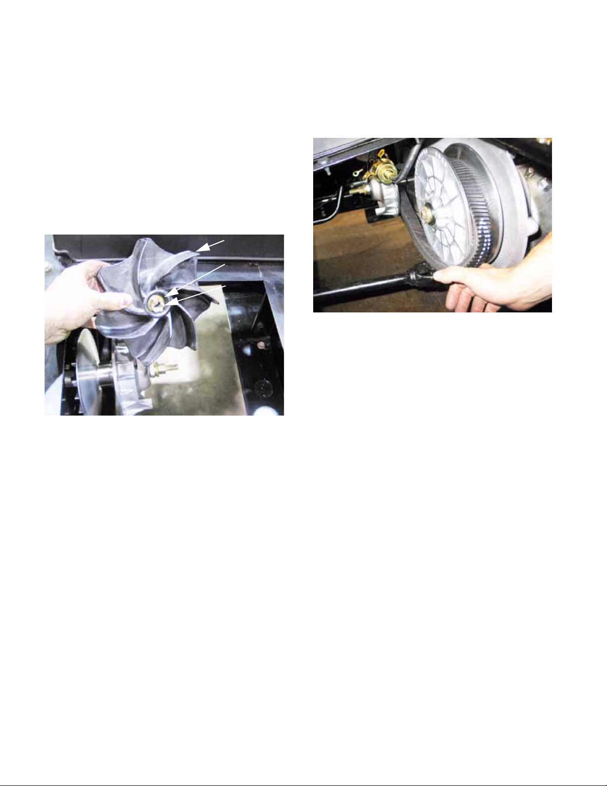
Caterpillar Enclosed CVT Addendum
7e. Adjust the number of shims (spacers)
behind the driven pulley to achieve correct alignment. Use the three .800” (2 cm)
I.D. flat washers that are included in the
kit, if necessary.
7f. Once alignment is correct, install the
driven pulley screw with thread locking
compound such as Loctite®
and tighten it to 32-36 ft-lb. (43-49 N-m).
7g. Install the cooling fan on the driving pulley,
securing it with the flat washer and castle
nut. See Figure 2b.28.
262 (red),
Fan
Washer
Castle nut
7j. Roll the drive belt back onto the pulleys.
Refer to the marks made before the belt
was removed, to confirm that the direction
of rotation has not been changed.
See Figure 2b.29.
Figure 2b.29
7k. Remove the screw that was used to
spread the sheaves of the driven pulley.
Figure 2b.28
7h. Tighten the nut to a torque of 22-25 ft-lbs.
(30-34 N-m), then secure it using the cotter pin.
7i. Inspect the drive belt. If it is worn to less
than 1.20” (30.5mm) across the flat back
surface of the belt, or if is shows signs of
burning or checking, replace it with a new
belt.
7l. Place the gear selector in neutral.
7m. Re-connect the negative battery cable.
7n. Clip a jumper wire from the eyelet on the
fuel pump ground wire to a good ground.
7o. Confirm that the drive belt area is clear,
and that no unsafe conditions will arise
from starting the engine.
7p. Start the engine briefly and confirm that
the CVT operates properly throughout the
engine RPM range, before installing the
CVT cover.
• The driven pulley should not rotate when the
engine is at idle speed.
• If the driven pulley does rotate at idle speed:
Re-check the spacing and alignment of the pulleys.
Confirm that the driving pulley is returning all the
way to rest position at idle.
84
Page 89

Caterpillar Enclosed CVT Addendum
8. FINAL ASSEMBLY
8a. Install the drain plug in the CVT cover, and
carefully tighten it until snug, using a 9/16”
wrench. See Figure 2b.30.
Drain plug
Figure 2b.30
8b. Slip the CVT cover in through the opening
in the passenger side of the seat box.
See Figure 2b.31.
8d. Fasten the CVT cover to the back plate
using the (12) 1/4-20 self tapping screws.
Tighten the screws using a 3/8” wrench.
See Figure 2b.32.
Figure 2b.32
8e. Mount the fuel pump to the console-cup
holder support. See Figure 2b.33.
Figure 2b.31
8c. Rotate the CVT cover down into position.
Console-cup holder support
Fuel pump mounting bolts
Fuel pump
“hot” wire
to fuel
pump
Figure 2b.33
NOTE: The star washer should be located under
the head of the bolt that the ground wire is
attached to, so that it bites through the paint to
establish a good electrical ground for the fuel
pump. Apply a small amount of silicone grease
to protect the joint from corrosion after the nuts
are tightened.
Ground wire
for fuel pump
Star
washer
85
Page 90

Caterpillar Enclosed CVT Addendum
8f. Position the air filter and intake tube in the
vehicle. See Figure 2b.34.
Air filter
intake tube
Figure 2b.34
• Remove the seals from the tube and the engine
air intake.
• Connect the tube to the engine intake manifold.
8g. Mount the air filter to the console-cup
holder support using the 5/16-18 nuts,
bolts, and spacer previously removed.
See Figure 2b.35.
8h. Reinstall the grab handle with the new
seat plate. See Figure 2b.36.
Flange bushings
Spacers
(secured with
tape to ease
mounting)
Figure 2b.36
8i. After the seat plate and grab handle are
installed, mount the fuel filter to the frame
using the 5/16-18 nuts and bolts previously removed.
8j. Use the opening in the new seat plate to
locate the tube support bracket. The
openings in the seat plate and the bracket
should be concentric.
Spacers
8k. Mark the points to drill mounting holes for
the tube support bracket.
8l. Center-punch and drill mounting holes in
the seat box using a 9/32” (7mm) drill bit.
8m. Mount the bracket beneath the front lip of
the seat box. Tighten the 1/4-14 screws
using a T-27 driver. See Figure 2b.37.
9/32” holes
Figure 2b.35
Tube support bracket
Figure 2b.37
86
Page 91

8n. Install the intake tube between the bracket
and the spigot on the front of the CVT
cover. Secure it with the hose clamp.
See Figure 2b.38.
Intake tube
Figure 2b.38
Caterpillar Enclosed CVT Addendum
8o. Install the passenger seat and its new
bracket to the new seat plate using a pair
of 1/2” wrenches. See Figure 2b.39.
Figure 2b.39
8p. Reinstall the engine cover and parcel bin.
8q. Lower the work-box and seats.
8r. Test-drive the vehicle in a safe place to
confirm that it operates properly before
returning it to service.
87
Page 92

Caterpillar Enclosed CVT Addendum88Chapter 3 - Drive System: Drive Shafts and Differentials
Page 93

CHAPTER 3 - DRIVE SYSTEM: DRIVE SHAFTS AND DIFFERENTIALS
DRIVE SYSTEM DESCRIPTION
1. Chapter 2 of this manual covers the drive system from the engine crankshaft to the output
shafts of the transfer case. Chapter 3 covers the
drive system down-stream of the transfer case.
This includes:
• The drive shafts from the transfer case to the differentials
• The front differential
• The rear differential
• The drive axles (half-shafts) that connect the differentials to the wheel hubs.
2. Drive shafts with Hooke-Spicer type universal
joints extend fore and aft from the output shafts
of the transfer case to drive the front and rear
differentials. See Figure 3.1.
Spicer-hooke type U-joint
4. The rear differential has a cast iron housing
and a cable-actuated locking feature.
See Figure 3.2.
Differential lock
actuator
Rear differential
Figure 3.2
5. The front differential has an aluminum housing, and an electrically controlled, slip sensing
Auto-Lok® feature. See Figure 3.3.
Figure 3.1
3. Both drive shafts (front and rear) are driven
whenever the transfer case is in gear , whether or
not four-wheel drive is engaged.
Front differential
5a. The front differential is engaged or disen-
gaged using a rocker switch on the dashboard. An electric clutch connects the
front differential pinion to the input shaft
when energized. When de-energized, the
input shaft is still driven by the drive shaft,
but the differential free-wheels.
Electrical connection for
Auto-Lok® feature
Figure 3.3
89
Page 94

Chapter 3 - Drive System: Drive Shafts and Differentials
5b. A cam/roller type over-running clutch
within the differential provides a limited
slip feature between the two front wheels.
5.3. Each differential transfers power to the drive
hubs through a drive shaft with Rzeppa-type
constant velocity joints at each end.
See Figure 3.4.
Figure 3.4
• In the event of a failure, the component will be
called back for engineering analysis and vendor
recovery.
• If the failure is warrantable, Cub Cadet will cover
the cost of replacement.
• If the failure is not warrantable, replacement will
be at the customer’s expense.
• Beyond the warranty period, internal parts for
the differentials will be made available so that
the dealer can repair or replace them at their
own discretion.
ADJUSTMENT: DIFFERENTIAL LOCK LINKAGE
1. The differential lock lever (located next to the
Hurst gear selector lever) operates on the rear
axle only:
• When engaged, the rear drive wheels are locked
together, eliminating differential action.
• When engaged, the differential lock improves
rear wheel traction at the expense of steering
response.
2. Proper use and operational behavior:
DRIVE SYSTEM: SERVICE INTENT
1. The transfer case is manufactured by Cub
Cadet. If it fails during the first two years, it
should be removed and replaced as a complete
unit.
• In the event of a failure, the transfer case will be
called back for engineering analysis.
• If the failure is warrantable, Cub Cadet will cover
the cost of replacement.
• If the failure is not warrantable, replacement will
be at the customer’s expense.
• Beyond the warranty period, internal parts will be
made available so that the dealer can repair or
replace the transfer case at their own discretion.
2. The remainder of the drive system (CVT, drive
shafts, axles, differentials) is purchased from
outside vendors.
• If any of these items fail in the first two years,
they should be removed and replaced with a
complete unit. The only exception to this may be
the axles. Rzeppa (Constant Velocity) joints
may be available to repair rather than replace
axles. Service intent has not been decided as
this manual goes to print.
• The operator should only engage the differential
lock when the vehicle is stationary
• Engaging the differential lock when there is great
disparity in the speed of the two rear tires will
cause immediate and severe damage to the rear
differential by shock-fracturing the differentia l
lock. This type of damage is readily apparent. It
is considered to be customer abuse, and is not
warrantable.
• For safest handling, the differential lock should
be used only as required for traction, then disengaged.
• When the differential lock cont rol le ve r is move d
to the disengaged position, the lock may remain
engaged until the drive load between the two
rear wheels equalizes, relaxing the load on the
lock mechanism. For example, if one wheel has
poor traction, or the vehicle is going around a
turn, the lock may not actually disengage until
the vehicle is stopped or driven in a straight line
on a surface that provides good traction.
3. To check the differential lock, lift and su pport the
rear of the vehicle in a safe manner .
CAUTION: Engagement of the 4-wheel drive
system (4X4 rocker switch located on the dashboard) with the engine running and the rear
wheels lifted may cause an accident.
90
Page 95

Chapter 3 - Drive System: Drive Shafts and Differentials
4. Manually rotate one rear wheel, with the differential lock disengaged:
• If the vehicle is in neutral, the drive shaft leading
from the transfer case to the differential will turn.
• If the transfer case is in gear, the other rear
wheel should rotate in the opposite direction.
5. Engage the differential lock and rot ate one rear
wheel:
• If the vehicle is in neutral, both rear wheels will
rotate in the same direction and the drive shaft
leading from the transfer case to the differential
will turn.
• If the transfer case is in gear, the wheel will be
extremely difficult to turn. The opposite rear
wheel will turn in the same direction, the driveshaft will turn, and the driven element of the CVT
will turn.
NOTE: It may take a few degrees of rotation
before the differential lock engages. It will emit
and audible “click” when it does.
6. If the differential lock fails to engage or disengage as it should, the problem may be internal,
or the problem may be in the linkage. Before
removing the differential, confirm that the problem does not lie in the linkage.
8. When the differential lock is engaged, there
should be about 3/4” (19mm) from the centerline
of the pin to the end housing that supports the
sealed carrier bearing. See Figure 3.6.
Engaged
.75”
Figure 3.6
9. To accommodate this roughly 3/8” (9.5mm) of
travel, the cable should be adjusted so that it is
just slack in the disengaged position.
See Figure 3.7.
7. Confirm that the linkage moves freely through its
range of travel.
When released, the center line of the pin that
connects the shift fork to the linkage should be
1-1/8” (32mm) from the end housing that supports the sealed carrier bearing.
See Figure 3.5.
Released
1.125”
Figure 3.5
Adjustment point
Figure 3.7
NOTE: There will be about 1/2” of free-play as
measured at the top of the control lever.
9.1. Loosen the jam nut and adjust the cable at the
differential bracket using a pair of 1/2” wrenches.
9.2. Tighten the jam nut and test the operati on of the
differential lock when adjustment is complete.
91
Page 96
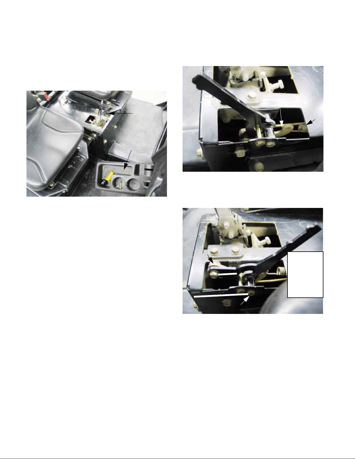
Chapter 3 - Drive System: Drive Shafts and Differentials
10. The control lever operates in a cam-over fashion, with an extension spring and pivot link
between the control lever and the cable.
11. Remove the console cover / cup holder to gain
access to the control lever connection.
See Figure 3.8.
Access to
differential
lock linkage
Console cover /
cup holder
removed
Figure 3.8
12. When the differential lock is released, the pivot
link is held horizontal by spring tension.
See Figure 3.9.
Pivot link
Spring
Figure 3.9
13. When the differential lock is engaged, the pivot
link is pulled up and forward. See Figure 13.0.
11a. Remove the knob from the Hurst gear
shift by turning it counter-clockwise.
11b. Remove the grip from the differential lock
control lever by pulling upward from the
base of the grip. A blow gun may be used
to force the grip off of the lever by shooting compressed air into the hole at the top
of the grip while lifting upward.
11c. Unbolt the console cover / cup holder
using a 9/16” wrench to remove the two
screws that hold the back of the console
cover. A 9/16” wrench can also be used
to loosen the two screws that secure the
front edge of the cover through slotted
holes.
11d. Lift the cover off to remove it.
Pivot
point
Fulcrum point
Figure 13.0
• The connection point where the link is bolted to
the lever moves above the fulcrum point of the
lever.
• The curvature of the link brings the connection
point to the spring above the fulcrum point as
well.
• This locks the linkage into the engaged position
until the lever is moved by the operator.
Cam-over
action holds
differential
lock in the
engaged
position.
92
Page 97
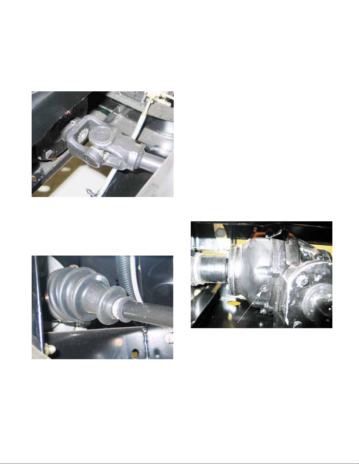
Chapter 3 - Drive System: Drive Shafts and Differentials
LUBRICATION
1. The universal joints in the driveshafts that connect the transfer case to the front and rear differentials are lubricated on assembly, and should
not need further lubrication in their normal service life. See Figure 3.10.
Figure 3.10
2. The constant velocity (Rzeppa type) joints in
the axle shafts that drive the wheels are lubricated on assembly, and should need no further
lubrication in their normal service life.
See Figure 3.11.
3. The rear differential contains roughly 32 fl.oz.
(950 ml.) of 80W-90 Low Foam Oil (Cub Cadet
P/N: 737-04040).
• The rear differential gear lube should be
changed after the first 50hrs. of use, and thereafter at 500 hr. intervals.
• Inspect the differential case vent at 100 hr. intervals. A blocked vent will cause fluid loss.
• The differential gear lube should be checked at
100 hr. intervals, unless fluid loss is noticed.
• In the event of fluid loss, identify and repair the
leak as soon as possible to prevent catastrophic
failure of the differential, disabling the vehicle.
CAUTION: The small volume of fluid contained
in the differential necessitates close monitoring
and prompt action if leakage is detected.
NOTE: Draining the rear differential for fluid
change requires the differential to be removed
from the vehicle or drained with a suction device.
4. To check the fluid in the rear differential:
See Figure 3.12.
Figure 3.11
NOTE: Grease is contained in the constant
velocity joint boots. If a boot is damaged, the
grease will get contaminated. Once the grease
is contaminated, accelerated wear and joint failure will occur. Replace any damaged boot as
soon as possible. Clean and inspect the boots
regularly.
Level plug
Figure 3.12
4a. Park the vehicle on a firm level surface.
4b. Allow the engine and drive system to cool
to ambient temperature.
4c. Tilt the cargo box up.
4d. Clean the area surrounding the vent and
level plug.
4e. Remove the level plug using a 1/4” allen
wrench, and check for the presence of
fluid at a level even with the bottom of the
threads.
93
Page 98
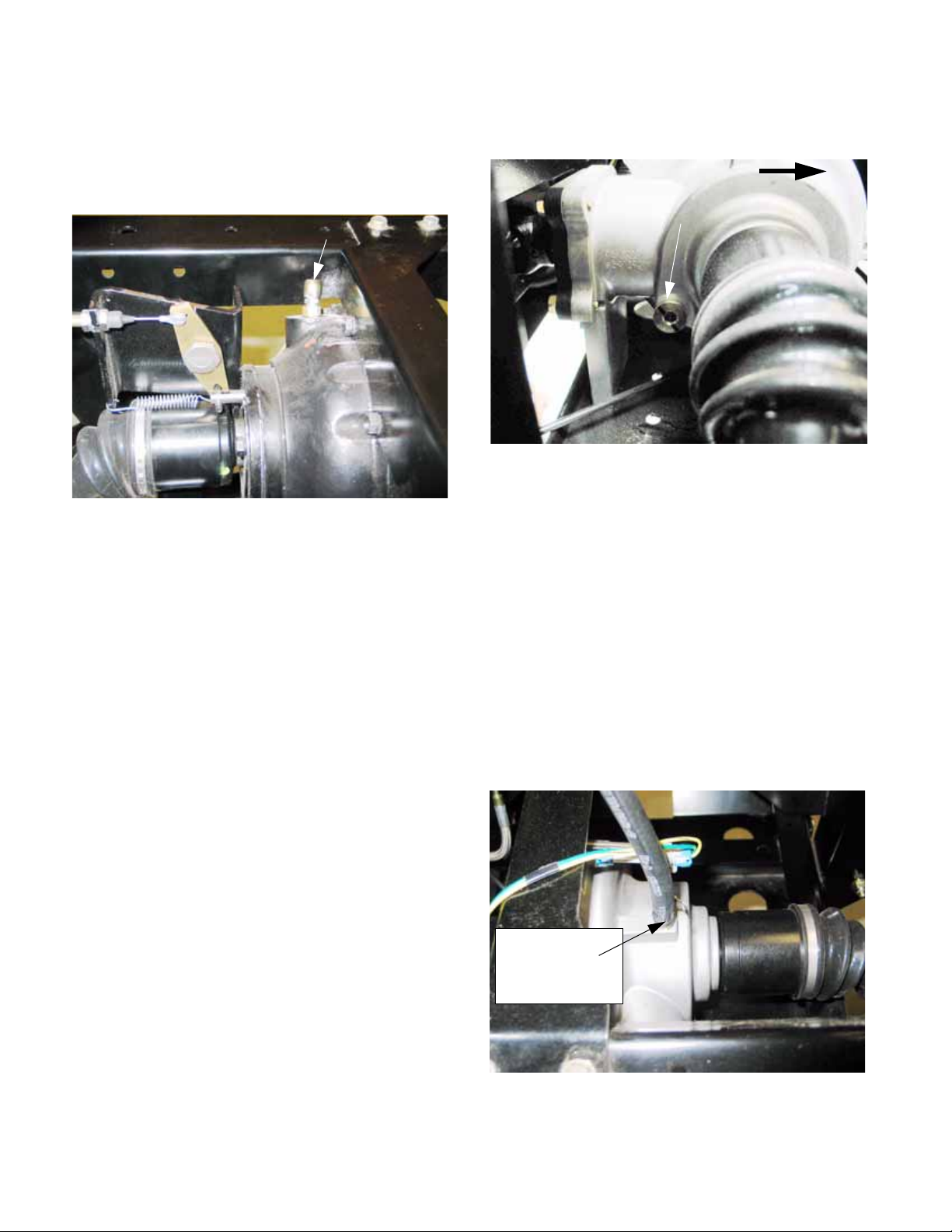
Chapter 3 - Drive System: Drive Shafts and Differentials
4f. If the fluid level is low, gear lube may be
added through the level plug, or through
the vent at the top of the differential housing. Use a 1/2” wrench to remove the
vent. See Figure 3.13.
Rear differential vent may be used as
a fill point
Figure 3.13
5. The front differential contains roughly 5 fl.oz.
(148 ml.) of Hydraulic Transmission Fluid (Cub
Cadet P/N: 737-3025 “red label”).
• In normal service, the front differential gear lube
should not need to be changed or replenished
unless leakage is noticed or the fluid has been
contaminated by submersion or similar mishap.
• Inspect the differential case vent at 100 hr. intervals. A blocked vent will cause fluid loss.
• The differential gear lube should be checked at
100 hr. interva ls, unless fluid loss is noticed.
6d. Clean the area surrounding the fill plug
and level plug. See Figure 3.14.
Front of vehicle
Front differential
level plug
Figure 3.14
6e. Remove the level plug using a 5/16” allen
wrench, and check for the presence of
fluid at a level even with the bottom of the
threads.
6f. Clean the level plug and inspect the o -ring
seal before installation. Replace the o-ring
if it is suspect.
6g. Tighten the level plug to a torque of 10 ft-
lbs (13.5 N-m).
7. If the fluid level is low, hydraulic transmission
fluid may be added through the level plug using
a pump, or through the vent at the top of the differential housing. Use a 7/16” wrench to disconnect the vent. See Figure 3.15.
• If fluid loss is noticed, identify and repair the leak
as soon as possible to prevent catastrophic failure.
NOTE: If the front differential is over-filled it may
“lock-up”. If this occurs, drain the fluid down to
the correct level. The differential should suffer no
loss of function or longevity.
6. To check the fluid in the front differential:
6a. Park the vehicle on a firm level surface.
6b. Allow the engine and drive system to cool
to ambient temperature.
6c. Tilt the hood forward to open it.
Front differential
vent may be
used as a
fill point
Figure 3.15
94
Page 99
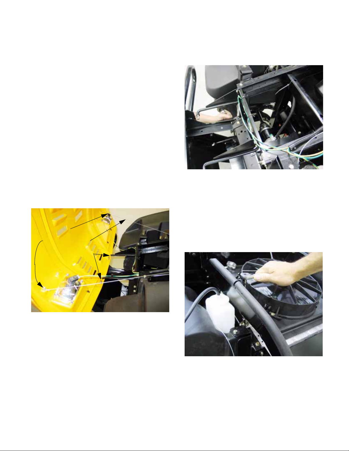
Chapter 3 - Drive System: Drive Shafts and Differentials
REMOVAL OF FRONT DRIVE SHAFT
NOTE: If the universal joints exhibit enough pla y
to indicate that they are worn, or if the front
driveshaft is identified as the source of a driveline vibration, replace the driveshaft as an
assembly.
NOTE: Both driveshafts are constantly engaged.
To identify vibration in one drive shaft, the other
must be disconnected. If the vibration goes
away when the shaft is disconnected, it is the
most likely source of the vibration.
1. Remove any front-mounted accessories from
the vehicle.
2. Lift and safely support the vehicle to provide
easier access to the bottom of the front differential.
NOTE: This procedure can be done on the
ground.
3. Remove the hood from the front of the vehicle to
provide easy access to the top of the front diff erential. See Figure 3.16.
Disconnect:
headlights
hood check cables
hairpin clips / hinges
4. Remove the six nuts and bolts that hold the
brush guard to the front of the frame, and
remove the brush guard. See Figure 3.17.
Figure 3.17
5. Diesel only: Move radiator for access.
5a. Disconnect the tube that leads to the radi-
ator over-flow bottle from the filler neck of
the radiator.
5b. Remove the four bolts that hold the cool-
ing matrix assembly (radiator, shroud,
cooling fan) to the frame using a 7/16”
wrench. See Figure 3.18.
Figure 3.16
3a. Open the hood
3b. Disconnect the headlights where the har-
ness plugs into the bulb holder, leaving
the bulb holder in the lamp.
3c. Remove the two internal cotter pins that
hold the hood panel to the hood brackets.
3d. Disconnect the check cables from the
hood using a 3/8” wrench.
3e. Slide the hood to the left of the vehicle to
disengage it from the brackets, and
remove it.
Figure 3.18
95
Page 100

Chapter 3 - Drive System: Drive Shafts and Differentials
5c. Carefully slide the cooling matrix straight
forward. Do not allow the radiator core to
come into contact with anything that might
damage it. See Figure 3.19.
Figure 3.19
NOTE: A piece of corrugated cardboard may be
placed under the radiator for protection. Failure
to remove the cardboard when the radiator is remounted can result in engine over-heating and
extensive damage.
6c. Lift the rear of the cover, and draw it back
to disengage the locating tabs at the front
edge. Remove the driveshaft cover.
7. Disconnect the driveshaft from the front differential:
NOTE: The front of the drive shaft is secured to
the pinion shaft on the front differential by a tension pin.
7a. Rotate the driveshaft as necessary to
reach the tension pin, maintaining enough
clearance to drive the tension pin out the
opposite side of the joint.
7b. Drive the tension pin out of the joint using
1/4” (6.5mm) flat-nosed drift.
See Figure 3.21.
Tension
Front driveshaft
pin
6. Remove the driveshaft cover: See Figure 3.20.
Push-in
fasteners
Mounting
screws
Driveshaft
cover
Figure 3.20
6a. Remove the four bolts that hold the drive-
shaft cover to the floor of the passenger
compartment using a 1/2” wrench.
6b. Pry-up the push-in fasteners that secure
the front of the driveshaft cover.
Figure 3.21
NOTE: Dispose of the tension pin, and re place it
with a fresh 5/16” X 1-1/4” tension pin.
96
 Loading...