

Page 1

Safe Operation Practices • Set-Up • Operation • Maintenance • Service • Troubleshooting • Warranty
OPERATOR'S MANUAL
Zero Turn Riding Mower
CUB CADET LLC, P.O. BOX 361131 CLEVELAND, OHIO 44136-0019
PrintedIn USA
Time Saver Model
i1042
FORMNO.769-03654
(Nov,2007)
Page 2
ToTheOwner
ThankYou
1
Thank you for purchasing a Lawn Tractor manufactured by Cub
Cadet LLC. It was carefully engineered to provide excellent
performance when properly operated and maintained.
Please read this entire manual prior to operating the equipment.
It instructs you how to safely and easily set up, operate and
maintain your machine. Please be sure that you, and any other
persons who will operate the machine, carefully follow the
recommended safety practices at all times. Failure to do so could
result in personal injury or property damage.
All information in this manual is relative to the most recent
product information available at the time of printing. Review
this manual frequently to familiarize yourself with the machine,
its features and operation. Please be aware that this Operator's
Manual may cover a range of product specifications for various
models. Characteristics and features discussed and/or illustrated
in this manual may not be applicable to all models. Cub Cadet
LLC reserves the right to change product specifications, designs
and equipment without notice and without incurring obligation.
Table of Contents
Safe Operation Practices ........................................ 3
Assembly & Set-Up .................................................. 8
Controls & Features ................................................ 9
Opera tion ................................................................ 12
Maintenance & Adjustment ................................. 15
This product has met the rigid safety standards of the Outdoor
Power Equipment Institute and an independent testing
laboratory. If you have any problems or questions concerning
the machine, phone your local Cub Cadet dealer or contact us
directly. Cub Cadet's Customer Support telephone numbers,
website address and mailing address can be found on this page.
We want to ensure your complete satisfaction at all times.
Throughout this manual, all references to right and left side of the
machine are observed from the operating position.
Service .................................................................... 20
Troubleshooting .................................................... 25
Replacement Parts ............................................... 26
Attachments & Accessories .................................. 26
Warranty ................................................. Back Cover
RecordProductInformation
Before setting up and operating your new equipment, please
locate the model plate on the equipment and record the
information in the provided area to the right. You can locate the
model plate by looking beneath the seat. This information will be
necessary, should you seek technical support via our web site or
with your local Cub Cadet dealer.
MODEL NUMBER
DDDDDDDDDDD
SERIAL NUMBER
DDDDDDDDDDD
CustomerSupport
If you have difficulty assembling this product or have any questions regarding the controls, operation, or maintenance of
this machine, you can seek help from the experts. Choose from the options below:
0 Visit us on the web at www.cubcadetcom
0 Locate your nearest Cub Cadet Dealer at (877) 282-8684
0 Write us at Cub Cadet LLC • P.O. Box 361131 • Cleveland, OH • 44136-0019
Page 3
ImportantSafeOperationPractices
WARNING: This symbol points out important safety instructions which, if not followed,
could endanger the personal safety and/or property of yourself and others. Read and follow
all instructions in this manual before attempting to operate this machine. Failure to comply
with these instructions may result in personal injury.
When you see this symbol. HEED ITS WARNING!
CALIFORNIA PROPOSITION 65
WARNING: Engine Exhaust, some of its constituents, and certain vehicle components
contain or emit chemicals known to State of California to cause cancer and birth defects
or other reproductive harm.
WARNING: Battery posts, terminals, and related accessories contain lead and lead
compounds, chemicals known to the State of California to cause cancer and reproductive
harm. Wash hands after handling
DANGER: This machine was built to be operated according to the rules for safe operation
practices in this manual. As with any type of power equipment, carelessness or error on the
part of the operator can result in serious injury. This machine is capable of amputating hands
and feet and throwing objects. Failure to observe the following safety instructions could
result in serious injury or death.
2
Children
1.
Tragic accidents can occur if the operator is not alert to the
presence of children. Children are often attracted to the
machine and the mowing activity. They do not understand
the dangers. Never assume that children will remain where
you last saw them.
a. Keep children out of the mowing area and in
watchful care of a responsible adult other than the
operator.
b. Be alert and turn machine off if a child enters the
area.
c. Before and while backing, look behind and down for
small children.
d. Never carry children, even with the blade(s) shut off.
They may fall off and be seriously injured or interfere
with safe machine operation.
e. Use extreme care when approaching blind corners,
doorways, shrubs, trees or other objects that may
block your vision of a child who may run into the
machine.
To avoid back-over accidents, always disengage
the cutting blade(s) before shifting into Reverse.
If equipped, the "Reverse Caution Mode" should
not be used when children or others are around.
g. Keep children away from hot or running engines.
They can suffer burns from a hot muffler.
h. Remove key when machine is unattended to
prevent unauthorized operation.
2.
Never allow children under 14 years of age to operate this
machine. Children 14 and over should read and understand
the instructions and safe operation practices in this manual
and on the machine and should be trained and supervised
by an adult.
Operation
SafeHandlingofGasoline:
1. To avoid personal injury or property damage use extreme
care in handling gasoline. Gasoline is extremely
flammable and the vapors are explosive. Serious
personal injury can occur when gasoline is spilled on
yourself or your clothes which can ignite. Wash your skin
and change clothes immediately.
a. Use only an approved gasoline container.
b. Never fill containers inside a vehicle or on a truck
or trailer bed with a plastic liner. Always place
containers on the ground away from your vehicle
before filling.
Page 4
c. Whenpractical,removegas-poweredequipment
fromthetruckortrailerandrefuelitontheground.
Ifthisisnotpossible,thenrefuelsuchequipmenton
atrailerwithaportablecontainer,ratherthanfroma
gasolinedispensernozzle.
d. Keepthenozzleincontactwiththerimofthefuel
tankorcontaineropeningatalltimesuntilfuelingis
complete.Donotuseanozzlelock-opendevice.
e. Extinguishallcigarettes,cigars,pipesandother
sourcesofignition.
f. Neverfuelmachineindoors.
g. Neverremovegascaporaddfuelwhiletheengine
ishotorrunning.Allowenginetocoolatleasttwo
minutesbeforerefueling.
h. Neveroverfillfueltank.Filltanktonomorethan1/2
inchbelowbottomoffillernecktoallowspacefor
fuelexpansion.
i. Replacegasolinecapandtightensecurely.
j. Ifgasolineisspilled,wipeitofftheengineand
equipment.Movemachinetoanotherarea.Wait5
minutesbeforestartingtheengine.
k. Toreducefirehazards,keepmachinefreeofgrass,
leaves,orotherdebrisbuild-up.Cleanupoilorfuel
spillageandremoveanyfuelsoakeddebris.
I. Neverstorethemachineorfuelcontainerinside
wherethereisanopenflame,sparkorpilotlight
asonawaterheater,spaceheater,furnace,clothes
dryerorothergasappliances.
m. Allowamachinetocoolatleastfiveminutesbefore
storing.
GeneralOperation:
1. Read, understand, and follow all instructions on the
machine and in the manual(s) before attempting to
assemble and operate. Keep this manual in a safe place for
future and regular reference and for ordering replacement
parts.
2. Be familiar with all controls and their proper operation.
Know how to stop the machine and disengage them
quickly.
3. Never allow children under 14 years old to operate this
machine. Children 14 years old and over should read and
understand the operation instructions and safety rules in
this manual and should be trained and supervised bya
parent.
4. Never allow adults to operate this machine without proper
instruction.
5. To help avoid blade contact or a thrown object injury,
keep bystanders, helpers, children and pets at least 75 feet
from the machine while it is in operation. Stop machine if
anyone enters the area.
6. Thoroughly inspect the area where the equipment is to be
used. Remove all stones, sticks, wire, bones, toys, and other
foreign objects which could be picked up and thrown by
the blade(s). Thrown objects can cause serious personal
injury.
7. Plan your mowing pattern to avoid discharge of material
toward roads, sidewalks, bystanders and the like. Also,
avoid discharging material against a wall or obstruction
which may cause discharged material to ricochet back
toward the operator.
8. Always wear safety glasses or safety goggles during
operation and while performing an adjustment or repair
to protect your eyes. Thrown objects which ricochet can
cause serious injury to the eyes.
9. Wear sturdy, rough-soled work shoes and close-fitting
slacks and shirts. Loose fitting clothes and jewelry can be
caught in movable parts. Never operate this machine in
bare feet or sandals.
10. Be aware of the mower and attachment discharge direction
and do not point it at anyone. Do not operate the mower
without the discharge cover or entire grass catcher in its
proper place.
11. Do not put hands or feet near rotating parts or under the
cutting deck. Contact with the blade(s) can amputate
hands and feet.
12. A missing or damaged discharge cover can cause blade
contact or thrown object injuries.
13. Stop the blade(s) when crossing gravel drives, walks, or
roads and while not cutting grass.
14. Watch for traffic when operating near or crossing
roadways. This machine is not intended for use on any
public roadway.
15. Do not operate the machine while under the influence of
alcohol or drugs.
16. Mow only in daylight or good artificial light.
17. Never carry passengers.
18. Disengage blade(s) before shifting into reverse. Back up
slowly. Always look down and behind before and while
backing to avoid a back-over accident.
19. Slow down before turning. Operate the machine smoothly.
Avoid erratic operation and excessive speed.
20. Disengage blade(s), set parking brake, stop engine and
wait until the blade(s) come to a complete stop before
removing grass catcher, emptying grass, unclogging chute,
removing any grass or debris, or making any adjustments.
21. Never leave a running machine unattended. Always turn
off blade(s), place transmission in neutral, set parking
brake, stop engine and remove key before dismounting.
22. Use extra care when loading or unloading the machine into
a trailer or truck. This machine should not be driven up or
down ramp(s), because the machine could tip over, causing
serious personal injury. The machine must be pushed
manually on ramp(s) to load or unload properly.
23.
Muffler and engine become hot and can cause a burn. Do
not touch.
24.
Check overhead clearances carefully before driving under
low hanging tree branches, wires, door openings etc.,
where the operator may be struck or pulled from the
machine, which could result in serious injury.
4 I SECTION 2-- IMPORTANT SAFE OPERATION PRACTICES
Page 5
25.
Disengage all attachment clutches, depress the brake
pedal completely and shift into neutral before attempting
to start engine.
26.
Your machine is designed to cut normal residential grass of
a height no more than 10". Do not attempt to mow through
unusually tall, dry grass (e.g., pasture) or piles of dry leaves.
Dry grass or leaves may contact the engine exhaust and/or
build up on the mower deck presenting a potential fire
hazard.
27. Use only accessories and attachments approved for this
machine by the machine manufacturer. Read, understand
and follow all instructions provided with the approved
accessory or attachment.
28. Data indicates that operators, age 60 years and above, are
involved in a large percentage of riding mower-related
injuries. These operators should evaluate their ability
to operate the riding mower safely enough to protect
themselves and others from serious injury.
29. If situations occur which are not covered in this manual, use
care and good judgment. Contact your customer service
representative for assistance.
SlopeOperation:
Slopes are a major factor related to loss of control and tip-over
accidents which can result in severe injury or death. All slopes
require extra caution. If you cannot back up the slope or if you
feel uneasy on it, do not mow it.
For your safety, use the slope gauge included as part of this
manual to measure slopes before operating this machine on
a sloped or hilly area. If the slope is greater than 15 degrees as
shown on the slope gauge, do not operate this machine on that
area or serious injury could result.
Do:
1. Mow up and down slopes, not across. Exercise extreme
caution when changing direction on slopes.
2. Watch for holes, ruts, bumps, rocks, or other hidden
objects. Uneven terrain could overturn the machine. Tall
grass can hide obstacles.
3. Use slow speed. Choose a low enough speed setting so
that you will not have to stop or shift while on the slope.
Tires may lose traction on slopes even though the brakes
are functioning properly. Always keep machine in gear
when going down slopes to take advantage of engine
braking action.
4. Follow the manufacturer's recommendations for wheel
weights or counterweights to improve stability.
5. Use extra care with grass catchers or other attachments.
These can change the stability of the machine.
6. Keep all movement on the slopes slow and gradual. Do
not make sudden changes in speed or direction. Rapid
engagement or braking could cause the front of the
machine to lift and rapidly flip over backwards which could
cause serious injury.
7. Avoid starting or stopping on a slope. If tires lose traction,
disengage the blade(s) and proceed slowly straight down
the slope.
DoNot:
1. Do not turn on slopes unless necessary; then, turn slowly
and gradually downhill, if possible.
2. Do not mow near drop-offs, ditches or embankments. The
mower could suddenly turn over if a wheel is over the edge
of a cliff, ditch, or if an edge caves in.
3. Do not try to stabilize the machine by putting your foot on
the ground.
4. Do not use a grass catcher on steep slopes.
5. Do not mow on wet grass. Reduced traction could cause
sliding.
6. Do not shift to neutral and coast downhill. Over-speeding
may cause the operator to lose control of the machine
resulting in serious injury or death.
7. Do not tow heavy pull behind attachments (e.g. loaded
dump cart, lawn roller, etc.) on slopes greater than 5
degrees. When going down hill, the extra weight tends
to push the tractor and may cause you to loose control.
(e.g. tractor may speed up, braking and steering ability are
reduced, attachment may jack-knife and cause tractor to
overturn).
Towing:
1. Tow only with a machine that has a hitch designed for
towing. Do not attach towed equipment except at the
hitch point.
2. Follow the manufacturers recommendation for weight
limits for towed equipment and towing on slopes.
3. Never allow children or others in or on towed equipment.
4. On slopes, the weight of the towed equipment may cause
loss of traction and loss of control.
5. Travel slowly and allow extra distance to stop.
6. Do not shift to neutral and coast downhill.
Service
1. Never run an engine indoors or in a poorly ventilated area.
Engine exhaust contains carbon monoxide, an odorless,
and deadly gas.
2. Before cleaning, repairing, or inspecting, make certain the
blade(s) and all moving parts have stopped. Disconnect the
spark plug wire and ground against the engine to prevent
unintended starting.
3. Periodically check to make sure the blades come to
complete stop within approximately (5) five seconds after
operating the blade disengagement control. If the blades
do not stop within the this time frame, your machine
should be serviced professionally by an authorized MTD
Service Dealer.
4.
Check brake operation frequently as it is subjected to wear
during normal operation. Adjust and service as required.
SECTION2 -- IMPORTANT SAFE OPERATION PRACTICES S
Page 6
5. Check the blade(s) and engine mounting bolts at frequent
intervals for proper tightness. Also, visually inspect blade(s)
for damage (e.g., excessive wear, bent, cracked). Replace
the blade(s) with the original equipment manufacturer's
(O.E.M.) blade(s) only, listed in this manual. "Use of parts
which do not meet the original equipment specifications
may lead to improper performance and compromise
safety!"
6. Mower blades are sharp. Wrap the blade or wear gloves,
and use extra caution when servicing them.
7. Keep all nuts, bolts, and screws tight to be sure the
equipment is in safe working condition.
8. Never tamper with the safety interlock system or other
safety devices. Check their proper operation regularly.
9. After striking a foreign object, stop the engine, disconnect
the spark plug wire(s) and ground against the engine.
Thoroughly inspect the machine for any damage. Repair
the damage before starting and operating.
10. Never attempt to make adjustments or repairs to the
machine while the engine is running.
11. Grass catcher components and the discharge cover are
subject to wear and damage which could expose moving
parts or allow objects to be thrown. For safety protection,
frequently check components and replace immediately
with original equipment manufacturer's (O.E.M.) parts only,
listed in this manual. "Use of parts which do not meet the
original equipment specifications may lead to improper
performance and compromise safety!"
12. Do not change the engine governor settings or over-speed
the engine. The governor controls the maximum safe
operating speed of the engine.
13. Maintain or replace safety and instruction labels, as
necessary.
14. Observe proper disposal laws and regulations for gas, oil,
etc. to protect the environment.
Notice Regarding Emissions
Engines which are certified to comply with California and federal
EPA emission regulations for SORE (Small Off Road Equipment)
are certified to operate on regular unleaded gasoline, and
may include the following emission control systems: Engine
Modification (EM) and Three Way Catalyst (TWC) if so equipped.
SparkArrestor
internal combustion engine and should not be used
_ ARNING: This machine is equipped with an
any).
If a spark arrester is used, it should be maintained in effective
working order by the operator. In the State of California the
above is required by law (Section 4442 of the California Public
Resources Code). Other states may have similar laws. Federal laws
apply on federal lands.
A spark arrester for the muffler is available through your
nearest engine authorized service dealer or contact the service
department, P.O. Box 361131 Cleveland, Ohio 44136-0019.
Average Useful Life
According to the Consumer Products Safety Commission
(CPSC) and the U.S. Environmental Protection Agency (EPA),
this product has an Average Useful Life of seven (7) years, or 270
hours of operation. At the end of the Average Useful Life, buy
a new machine or have the machine inspected annually by an
authorized service dealer to ensure that all mechanical and
safety systems are working properly and not worn excessively.
Failure to do so can result in accidents, injuries or death.
on or near any unimproved forest-covered,
brushcovered or grass-covered land unless the
engine's exhaust system is equipped with a spark
arrester meeting applicable local or state laws (if
Donot modify engine
To avoid serious injury or death, do not modify engine in any
way. Tampering with the governor setting can lead to a runaway
engine and cause it to operate at unsafe speeds. Never tamper
with factory setting of engine governor.
WARNING: Your Responsibility--Restrict the use of this power machine to persons who read, understand and
follow the warnings and instructions in this manual and on the machine.
6 I SECTION 2-- IMPORTANT SAFE OPERATION PRACTICES
SAVETHESEINSTRUCTIONS!
Page 7
Sight and
hold this level with avertical tree...
or a corner of a building...
i -4 or a fence post
I I
I I
I I
' Foldo,_ ',
, _ _epresents_a 15°
I
15 °
I--
U
a.
Z
0
0
I
z
£
I--
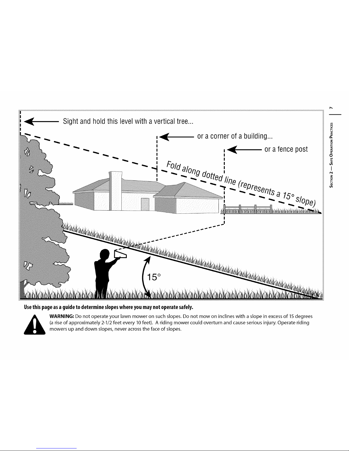
Usethis pageasa guideto determineslopeswhereyou maynot operatesafely.
WARNING: Do not operate your lawn mower on such slopes. Do not mow on inclines with a slope in excess of 15 degrees
(a rise of approximately 2-1/2 feet every 10 feet). A riding mower could overturn and cause serious injury. Operate riding
mowers up and down slopes, never across the face of slopes.
Page 8
Assembly&Set-Up
3
Opening the Tractor Hood
To attach the negative battery cable and check the engine
oil level the hood must be open. Locate the hood lift notch
(Refer to Figure 4 on page 10)at the front/center of the
dash panel. Grasping the hood at the notch, lift and pivot
the hood forward to open.
Attaching the Battery Cables
The tractor is shipped with an activated sealed battery. The
positive battery cable is factory connected. The negative
cable must be connected. The positive battery terminal is
marked Pos. (+). The negative battery terminal is marked
Neg. (-).
IMPORTANT: Make sure the ignition switch is in the "OFF"
position before attaching the battery cables.
• From the center notch at the front of the dash panel,
lift the tractor hood and pivot forward to open.
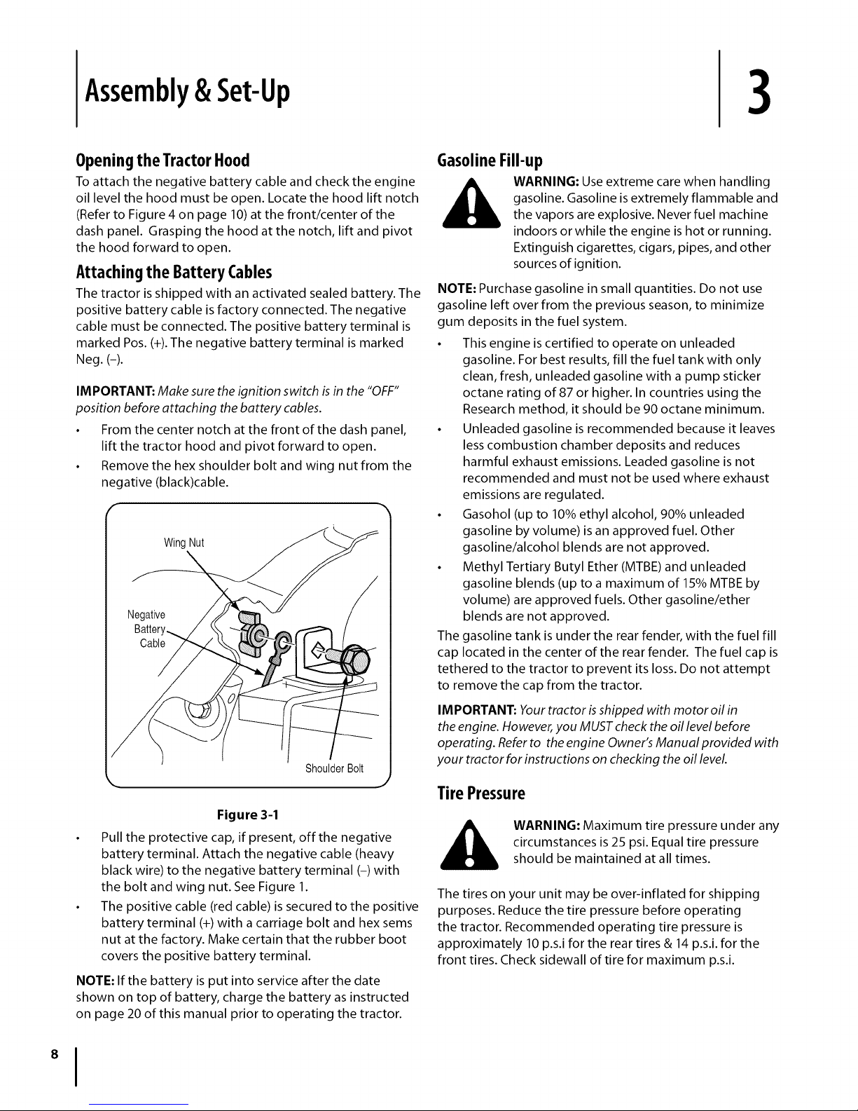
• Remove the hex shoulder bolt and wing nut from the
negative (black)cable.
Wing Nut
Negative
Cable
GasolineFill-up
__, ARNING: Use extreme care when handling
NOTE: Purchase gasoline in small quantities. Do not use
gasoline left over from the previous season, to minimize
gum deposits in the fuel system.
• This engine is certified to operate on unleaded
gasoline. For best results, fill the fuel tank with only
clean, fresh, unleaded gasoline with a pump sticker
octane rating of 87 or higher. In countries using the
Research method, it should be 90 octane minimum.
• Unleaded gasoline is recommended because it leaves
less combustion chamber deposits and reduces
harmful exhaust emissions. Leaded gasoline is not
recommended and must not be used where exhaust
emissions are regulated.
• Gasohol (up to 10% ethyl alcohol, 90% unleaded
gasoline by volume) is an approved fuel. Other
gasoline/alcohol blends are not approved.
• Methyl Tertiary Butyl Ether (MTBE) and unleaded
gasoline blends (up to a maximum of 15% MTBE by
volume) are approved fuels. Other gasoline/ether
blends are not approved.
The gasoline tank is under the rear fender, with the fuel fill
cap located in the center of the rear fender. The fuel cap is
tethered to the tractor to prevent its loss. Do not attempt
to remove the cap from the tractor.
gasoline. Gasoline is extremely flammable and
the vapors are explosive. Never fuel machine
indoors or while the engine is hot or running.
Extinguish cigarettes, cigars, pipes, and other
sources of ignition.
I
Figure 3-1
Pull the protective cap, if present, off the negative
battery terminal. Attach the negative cable (heavy
black wire) to the negative battery terminal (-) with
the bolt and wing nut. See Figure 1.
The positive cable (red cable) is secured to the positive
battery terminal (+) with a carriage bolt and hex sems
nut at the factory. Make certain that the rubber boot
covers the positive battery terminal.
NOTE: If the battery is put into service after the date
shown on top of battery, charge the battery as instructed
on page 20 of this manual prior to operating the tractor.
ShoulderBolt
IMPORTANT: Yourtractor h shipped with motor oil in
theengine. However,you MUSTcheckthe oil levelbefore
operating. Referto theengine Owner'sManual provided with
your tractor for instructions on checking the oil level
TirePressure
circumstances is 25 psi. Equal tire pressure
WARNING: Maximum tire pressure under any
should be maintained atall times.
The tires on your unit may be over-inflated for shipping
purposes. Reduce the tire pressure before operating
the tractor. Recommended operating tire pressure is
approximately 10 p.s.i for the rear tires & 14 p.s.i, for the
front tires. Check sidewall of tire for maximum p.s.i.
Page 9
ControlsandFeatures
f
4
D
B
C
E
\
P
F
H
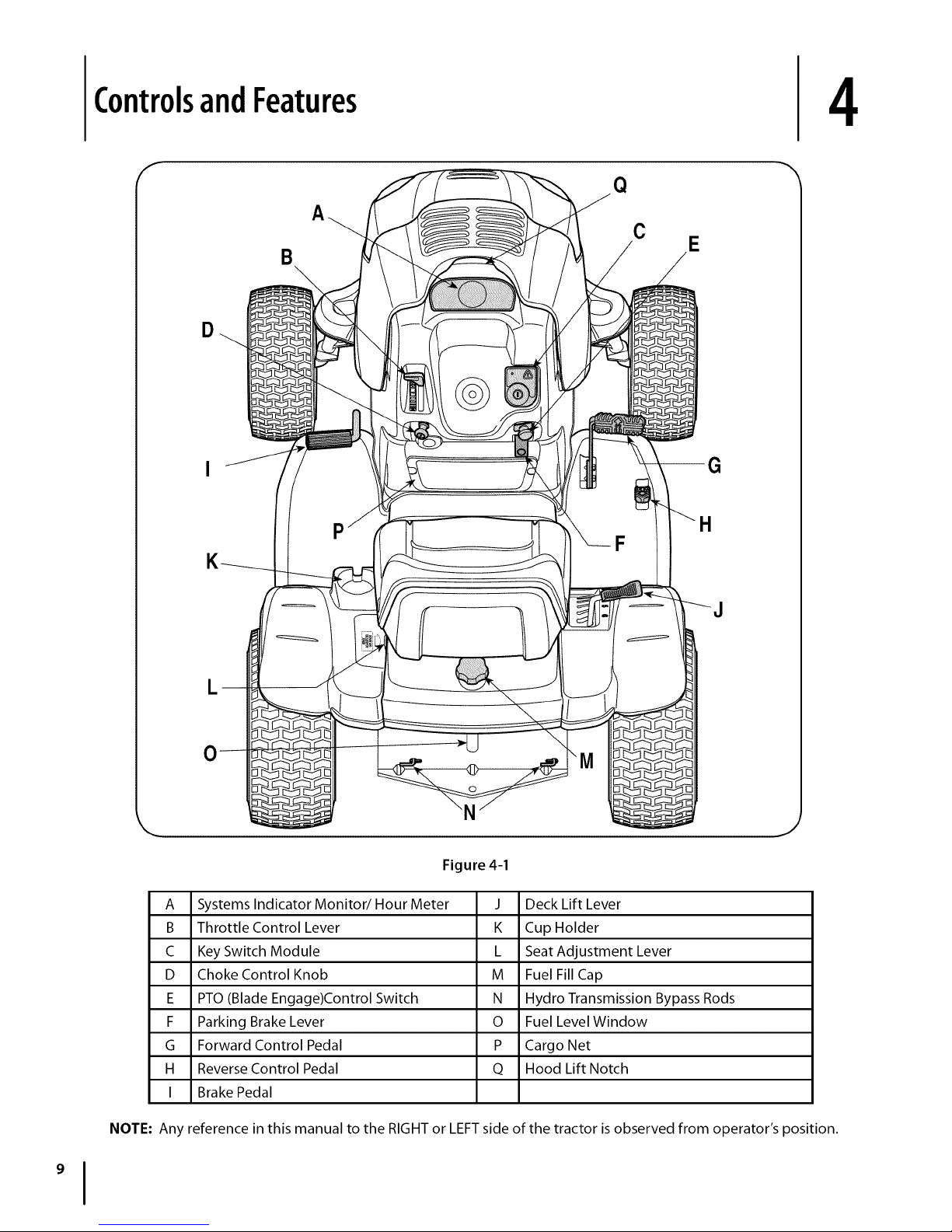
A Systems Indicator Monitor/Hour Meter
B Throttle Control Lever
C Key Switch Module
D Choke Control Knob
E PTO (Blade Engage)Control Switch
F Parking Brake Lever
G Forward Control Pedal
H Reverse Control Pedal
I Brake Pedal
NOTE: Any reference in this manual to the RIGHT or LEFT side of the tractor is observed from operator's position.
J
Figure 4-1
J Deck Lift Lever
K Cup Holder
L Seat Adjustment Lever
M Fuel Fill Cap
N Hydro Transmission Bypass Rods
O Fuel Level Window
P Cargo Net
Q Hood Lift Notch
Page 10
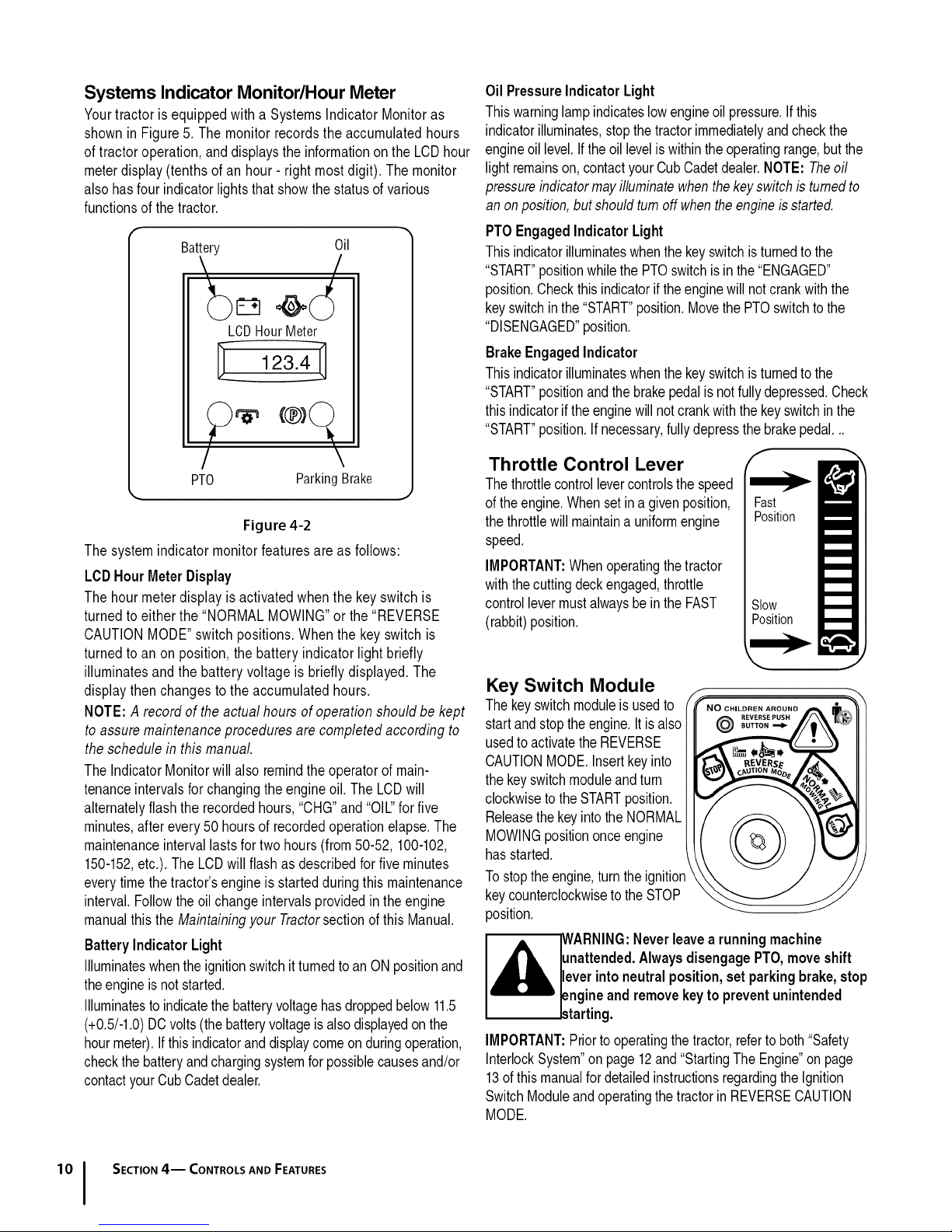
Systems Indicator Monitor/Hour Meter
Yourtractoris equippedwith a SystemsIndicator Monitoras
shownin Figure5. The monitorrecordsthe accumulatedhours
oftractor operation,anddisplaysthe informationontheLCDhour
meterdisplay(tenthsof an hour- right mostdigit). Themonitor
alsohas fourindicatorlights thatshowthe statusof various
functionsof the tractor.
Battery Oil
LCDHourMeter
123.4-
Oil PressureIndicatorLight
Thiswarninglampindicateslowengineoilpressure.Ifthis
indicatorilluminates,stopthetractorimmediatelyandcheckthe
engineoil level.If theoillevelis withintheoperatingrange,butthe
lightremainson,contactyourCubCadetdealer.NOTE:Theoil
pressureindicatormayilluminatewhenthekeyswitchis turnedto
an onposition,butshouldturn offwhentheengineisstarted.
PTOEngagedIndicator Light
Thisindicatorilluminateswhenthe keyswitchisturnedtothe
"START"positionwhilethe PTOswitchis inthe "ENGAGED"
position.Checkthisindicatorifthe enginewillnotcrankwiththe
keyswitchinthe"START"position.Movethe PTOswitchtothe
"DISENGAGED"position.
BrakeEngaged Indicator
Thisindicatorilluminateswhenthe keyswitchisturnedtothe
"START"positionandthebrakepedalis notfullydepressed.Check
thisindicatorifthe enginewillnotcrankwiththekeyswitchin the
"START"position.Ifnecessary,fullydepressthe brakepedal._
/
PTO ParkingBrake
Figure 4-2
Thesystem indicator monitorfeaturesareas follows:
LCDHourMeterDisplay
Thehour meterdisplay is activatedwhen the keyswitchis
turnedto either the "NORMALMOWING"orthe "REVERSE
CAUTIONMODE"switchpositions. Whenthe key switchis
turnedto an on position, the batteryindicator lightbriefly
illuminatesand the batteryvoltage is brieflydisplayed.The
displaythen changesto theaccumulatedhours.
NOTE:A record of theactual hours of operationshould be kept
to assuremaintenanceproceduresare completedaccordingto
the schedulein this manual.
TheIndicatorMonitorwill also remindtheoperatorof main-
tenanceintervalsfor changingthe engineoil. TheLCDwill
alternatelyflashthe recordedhours,"CHG"and"OIL"forfive
minutes,after every50 hoursof recordedoperationelapse.The
maintenanceintervallastsfor twohours (from50-52,100-102,
150-152,etc.). TheLCDwill flashas describedforfive minutes
everytimethetractor'sengineis startedduringthis maintenance
interval.Followthe oil changeintervalsprovidedintheengine
manualthis the Maintainingyour Tractorsection ofthis Manual.
Battery Indicator Light
Illuminateswhenthe ignitionswitchit turnedtoan ONpositionand
theengineis notstarted.
Illuminatesto indicatethe batteryvoltagehasdroppedbelow11.5
(+0.5/-1.0)DCvolts(the batteryvoltageis alsodisplayedon the
hourmeter).Ifthisindicatoranddisplaycomeon duringoperation,
checkthe batteryandchargingsystemforpossiblecausesand/or
contactyourCub Cadetdealer.
Throttle Control Lever
Thethrottlecontrollevercontrolsthe speed
ofthe engine.Whensetin a givenposition,
thethrottlewillmaintaina uniformengine
speed.
IMPORTANT:Whenoperatingthe tractor
withthecutting deckengaged,throttle
controllevermustalwaysbeinthe FAST
(rabbit)position.
f
Fast
Position
Slow
Position
Key Switch Module
Thekeyswitchmoduleisusedto
startand stopthe engine.Itis also
usedto activatetheREVERSE
CAUTIONMODE.Insertkeyinto
thekeyswitchmoduleandturn
clockwisetotheSTARTposition.
Releasethe keyintothe NORMAL
MOWINGpositiononceengine
hasstarted.
Tostopthe engine,turntheignitior
keycounterclockwiseto theSTOP
position.
lunattended.AlwaysdisengagePTO,moveshift
I,_ ARNING:Neverleave a runningmachine
IMPORTANT:Priortooperatingthetractor,refertoboth"Safety
InterlockSystem"on page12and"StartingTheEngine"on page
13ofthismanualfordetailedinstructionsregardingthe Ignition
SwitchModuleandoperatingthetractorinREVERSECAUTION
MODE.
Ileverintoneutralposition,setparkingbrake,stop
lengineandremovekeyto preventunintended
_starting.
SECTION4-- CONTROLS AND FEATURES
Page 11
,_ IWARNING:NevermovethekeyintotheStart
positionwhilethe engineisrunning.Doingso
maycausedamageto yourengine'sstarter,
Choke Control
Thechokecontrolknobislocatedon the lowerleftsideofthedash
paneland isactivatedbypullingoutward.Activatingthechoke
controlclosesthechokeplateonthe carburetorandaids instarting
theengine.
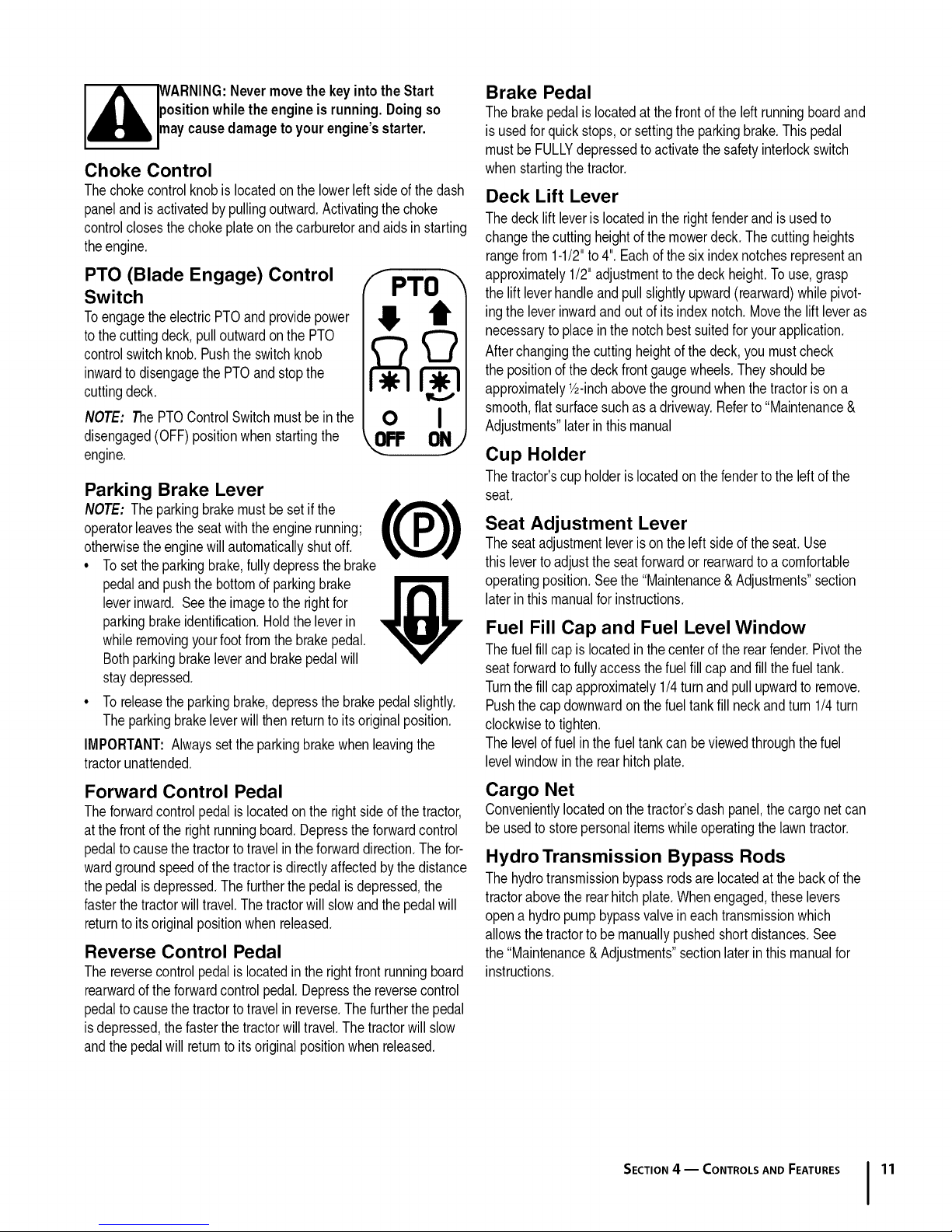
PTO (Blade Engage) Control
Switch
Toengagethe electricPTOand providepower
tothe cuttingdeck,pulloutwardonthePTO
controlswitchknob.Pushthe switchknob
inwardtodisengagethePTOandstopthe
cuttingdeck.
NOTE: ThePTOControlSwitchmustbein the
disengaged(OFF)positionwhen startingthe
engine.
F PTO
! /
o I
Parking Brake Lever
NOTE: Theparkingbrakemustbeset ifthe
operatorleavestheseatwiththeenginerunning;
otherwisetheenginewillautomaticallyshutoff.
• Tosettheparkingbrake,fullydepressthebrake
pedaland pushthe bottomofparkingbrake
leverinward. Seethe imagetothe rightfor
parkingbrakeidentification.Holdthe leverin
whileremovingyourfootfromthebrakepedal.
Bothparkingbrakeleverand brakepedalwill
staydepressed.
• Toreleasetheparkingbrake,depressthebrakepedalslightly.
Theparkingbrakeleverwillthen returnto itsoriginalposition.
IMPORTANT:Alwayssetthe parkingbrakewhenleavingthe
tractorunattended.
Brake Pedal
Thebrakepedalislocatedat thefrontof theleftrunningboardand
isusedforquickstops,or settingthe parkingbrake.Thispedal
mustbe FULLYdepressedto activatethesafetyinterlockswitch
whenstartingthetractor.
Deck Lift Lever
Thedecklift leverislocatedin therightfenderandisusedto
changethecuttingheightofthe mowerdeck. Thecuttingheights
rangefrom 1-1/2"to4".Eachofthesixindexnotchesrepresentan
approximately1/2"adjustmenttothe deckheight.Touse,grasp
thelift leverhandleandpullslightlyupward(rearward)whilepivot-
ingtheleverinwardandout ofits indexnotch.Movetheliftleveras
necessaryto placeinthe notchbestsuitedforyourapplication.
Afterchangingthecuttingheightofthe deck,you mustcheck
thepositionof thedeckfrontgaugewheels.Theyshouldbe
approximately1/2-inchabovethegroundwhenthetractorisona
smooth,flat surfacesuchasa driveway.Referto "Maintenance&
Adjustments"laterinthis manual
Cup Holder
Thetractor'scupholderislocatedonthefendertothe leftofthe
seat.
Seat Adjustment Lever
Theseatadjustmentleverisonthe left sideoftheseat.Use
thisleverto adjusttheseatforwardor rearwardto a comfortable
operatingposition.Seethe "Maintenance&Adjustments"section
laterin thismanualforinstructions.
Fuel Fill Cap and Fuel Level Window
Thefuel fillcap islocatedin thecenterof therearfender.Pivotthe
seatforwardtofullyaccessthefuelfill capandfill thefueltank.
Turnthefillcap approximately1/4turnandpullupwardto remove.
Pushthe capdownwardonthe fueltankfillneckandturn 1/4turn
clockwisetotighten.
Theleveloffuel in thefueltankcan beviewedthroughthefuel
levelwindowinthe rearhitchplate.
Forward Control Pedal
Theforwardcontrolpedalis locatedonthe rightsideof thetractor,
atthe frontofthe rightrunningboard.Depresstheforwardcontrol
pedaltocausethe tractortotravelintheforwarddirection.Thefor-
wardgroundspeedofthe tractoris directlyaffectedbythedistance
thepedalis depressed.Thefurtherthepedalis depressed,the
fasterthetractorwill travel.Thetractorwill slowandthepedalwill
returnto itsoriginalpositionwhenreleased.
Reverse Control Pedal
Thereversecontrolpedalis locatedin therightfrontrunningboard
rearwardoftheforwardcontrolpedal.Depressthereversecontrol
pedaltocausethe tractortotravelin reverse.Thefurtherthepedal
isdepressed,the fasterthe tractorwilltravel.Thetractorwillslow
andthepedalwill returnto itsoriginalpositionwhenreleased.
Cargo Net
Convenientlylocatedonthetractor'sdashpanel,thecargonetcan
be usedto storepersonalitemswhileoperatingthelawntractor.
Hydro Transmission Bypass Rods
Thehydrotransmissionbypassrodsarelocatedatthebackofthe
tractorabovetherearhitchplate.Whenengaged,theselevers
opena hydropumpbypassvalveineach transmissionwhich
allowsthetractorto bemanuallypushedshortdistances.See
the"Maintenance& Adjustments"sectionlaterinthis manualfor
instructions.
SECTION4 -- CONTROLS AND FEATURES 11
Page 12
Operation
5
F
WARNING
AVOID SERIOUS INJURY OR DEATH
• GO UP AND DOWN SLOPES, NOTACROSS.
• AVOID SUDDEN TURNS.
• DONOTOPERATETHEUNITWHEREITCOULDSLIPORTIR
• IFMACHINESTOPSGOINGUPHILL, STOP BLADE(S) AND
BACKDOWNHILLSLOWLY.
• DONOTMOWWHENCHILDRENOROTHERSAREAROUND.
• NEVERCARRYCHILDREN,EVENWITHBLADESOFE
• LOOKDOWNANDBEHINDBEFOREANDWHILEBACKING.
• KEEPSAFETYDEVICES(GUARDS, SHIELDS, AND
SWITCHES)INPLACEANDWORKING.
• REMOVEOBJECTSTHATCOULDBETHROWNBYTHE
BLADE(S).
• KNOWLOCATIONANDFUNCTIONOFALLCONTROLS.
• BESUREBLADE(S) ANDENGINEARESTOPPEDBEFORE
PLACINGHANDSORFEETNEARBLADE(S).
• BEFORELEAVINGOPERATOR'SPOSITION, DISENGAGE
BLADE(S), PLACETHESHIFTLEVERINNEUTRAL, ENGAGE
BRAKELOCK,SHUTENGINEOFFANDREMOVEKEY.
READ OPERATOR'S MANUAL
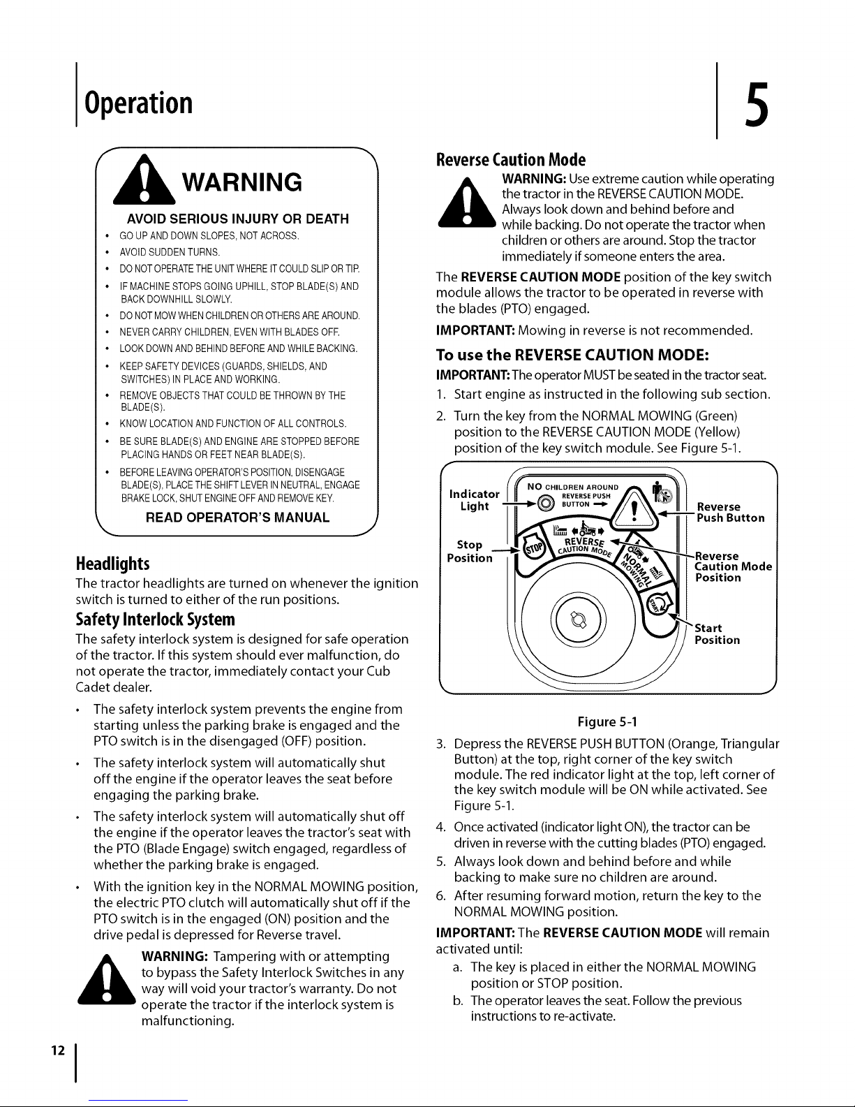
ReverseCaution Mode
the tractor in the REVERSECAUTION MODE.
,_ WARNING: Use extreme caution while operating
The REVERSE CAUTION MODE position of the key switch
module allows the tractor to be operated in reverse with
the blades (PTO) engaged.
IMPORTANT: Mowing in reverse is not recommended.
Always look down and behind before and
while backing. Do not operate the tractor when
children or others are around. Stop the tractor
immediately if someone enters the area.
To use the REVERSE CAUTION MODE:
IMPORTANT: The operator MUST be seated in the tractor seat.
1. Start engine as instructed in the following sub section.
2.
Turn the key from the NORMAL MOWING (Green)
position to the REVERSECAUTION MODE (Yellow)
position of the key switch module. See Figure 5-1.
. o,,.ooE.Aooo.oA
Indicator III _ ,_, BEVERSEPUSH//_ I1_111
Light __-_--I_ BUTTON_ J'/t\_ _y 111Reverse
_'_-_- PushButton
Headlights
The tractor headlights are turned on whenever the ignition
switch is turned to either of the run positions.
Safety Interlock System
The safety interlock system is designed for safe operation
of the tractor. If this system should ever malfunction, do
not operate the tractor, immediately contact your Cub
Cadet dealer.
• The safety interlock system prevents the engine from
starting unless the parking brake is engaged and the
PTO switch is in the disengaged (OFF) position.
• The safety interlock system will automatically shut
off the engine if the operator leaves the seat before
engaging the parking brake.
• The safety interlock system will automatically shut off
the engine if the operator leaves the tractor's seat with
the PTO (Blade Engage) switch engaged, regardless of
whether the parking brake is engaged.
• With the ignition key in the NORMAL MOWING position,
the electric PTO clutch will automatically shut off if the
PTO switch is in the engaged (ON) position and the
drive pedal is depressed for Reverse travel.
to bypass the Safety Interlock Switches in any
,_ WARNING: Tampering with or attempting
way will void your tractor's warranty. Do not
operate the tractor if the interlock system is
malfunctioning.
° t'tp° iiii
Figure 5-1
3. Depress the REVERSEPUSH BUTTON (Orange, Triangular
Button) at the top, right corner of the key switch
module. The red indicator light at the top, left corner of
the key switch module will be ON while activated. See
Figure 5-1.
4. Once activated (indicator light ON), the tractor can be
driven in reverse with the cutting blades (PTO)engaged.
5. Always look down and behind before and while
backing to make sure no children are around.
6. After resuming forward motion, return the key to the
NORMAL MOWING position.
IMPORTANT: The REVERSE CAUTION MODE will remain
activated until:
a. The key is placed in either the NORMAL MOWING
position or STOP position.
b. The operator leaves the seat. Follow the previous
instructions to re-activate.
Page 13
Startingthe Engine
,_ WARNING: Do not operate the tractor if the
NOTE: Refer to the engine Owner's Manual for gasoline
and oil fill-up instructions.
1. Insert the tractor key into the key switch module.
2. Disengage the PTO (Blade Engage) lever/knob.
3. Engage the tractor's parking brake.
4. Pull the choke control knob outward into the full choke
position (a warm engine may not require choking).
5. Move the throttle control lever to midway between the
SLOW and FAST positions.
6. Turn the ignition key clockwise to the START position.
After the engine starts, release the key. It will return to
the NORMAL MOWING position.
IMPORTANT: Do not hold the key in the START position
for longer than ten seconds at a time. Doing so may cause
damage to your engine's electric starter.
7. After the engine starts, gradually push the choke knob
fully inward as the engine warms up.
NOTE: Do not use the choke control to enrich the fuel
mixture, except as necessary to start and warm up the
engine.
interlock system is malfunctioning. This system
was designed for your safety and protection.
IMPORTANT
If leaving the tractor unattended, also turn the
ignition key offand remove the key.
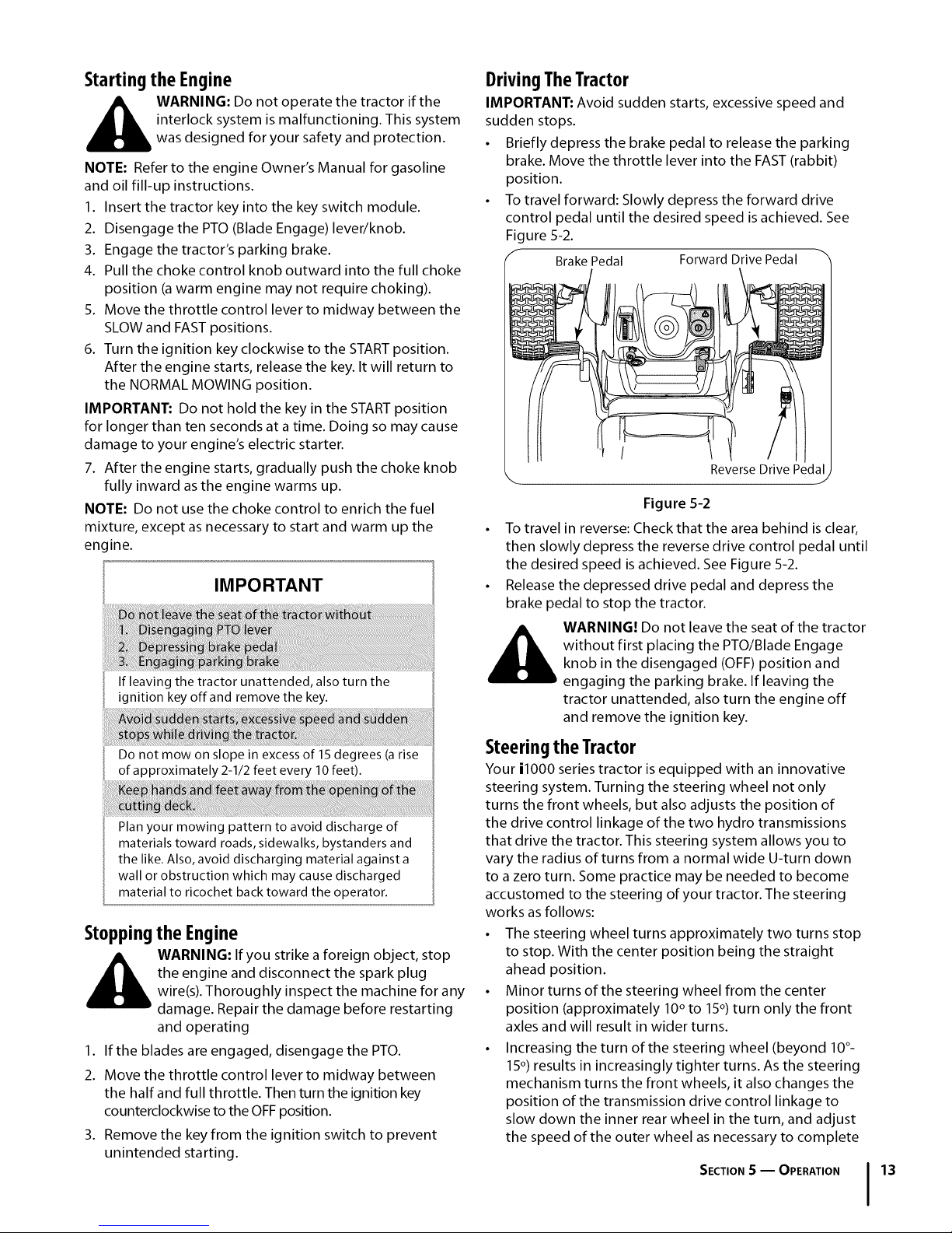
DrivingTheTractor
IMPORTANT: Avoid sudden starts, excessive speed and
sudden stops.
• Briefly depress the brake pedal to release the parking
brake. Move the throttle lever into the FAST (rabbit)
position.
• To travel forward: Slowly depress the forward drive
control pedal until the desired speed is achieved. See
Figure 5-2.
/r Brake Pedal Forward Drive Pedal "%
k, Reverse Drive Pedal/
Figure 5-2
To travel in reverse: Check that the area behind is clear,
then slowly depress the reverse drive control pedal until
the desired speed is achieved. See Figure 5-2.
Release the depressed drive pedal and depress the
brake pedal to stop the tractor.
WARNING! Do not leave the seat of the tractor
without first placing the PTO/Blade Engage
knob in the disengaged (OFF) position and
engaging the parking brake. If leaving the
tractor unattended, also turn the engine off
and remove the ignition key.
Do not mow on slope in excess of 15 degrees (a rise
of approximately 2-1/2 feet every 10 feet).
Plan your mowing pattern to avoid discharge of
materials toward roads, sidewalks, bystanders and
the like. Also, avoid discharging material against a
wall or obstruction which may cause discharged
material to ricochet back toward the operator.
Stoppingthe Engine
WARNING: If you strike a foreign object, stop
the engine and disconnect the spark plug
wire(s). Thoroughly inspect the machine for any
damage. Repair the damage before restarting
and operating
1. If the blades are engaged, disengage the PTO.
2. Move the throttle control lever to midway between
the half and full throttle. Then turn the ignition key
counterclockwise to the OFF position.
3. Remove the key from the ignition switch to prevent
unintended starting.
Steeringthe Tractor
Your i1000 series tractor is equipped with an innovative
steering system. Turning the steering wheel not only
turns the front wheels, but also adjusts the position of
the drive control linkage of the two hydro transmissions
that drive the tractor. This steering system allows you to
vary the radius of turns from a normal wide U-turn down
to a zero turn. Some practice may be needed to become
accustomed to the steering of your tractor. The steering
works as follows:
• The steering wheel turns approximately two turns stop
to stop. With the center position being the straight
ahead position.
• Minor turns of the steering wheel from the center
position (approximately 10° to 15°) turn only the front
axles and will result in wider turns.
• Increasing the turn of the steering wheel (beyond 10°-
15°) results in increasingly tighter turns. As the steering
mechanism turns the front wheels, it also changes the
position of the transmission drive control linkage to
slow down the inner rear wheel in the turn, and adjust
the speed of the outer wheel as necessary to complete
SECTION S -- OPERATION 13
Page 14
the desired turn. Turn the steering wheel back to the
center position as the turn is completed.
NOTE: It is not necessary to release the drive pedal when
making a turn. The change to the transmission linkage
occurs regardless of how far the drive pedal is depressed.
When the steering wheel is straightened, the tractor will
return to the speed set by the drive pedal.
• Turning the steering wheel fully to its stop in either
direction will fully turn the front wheels, reverse the
direction of the inner wheel and adjust the outer wheel
speed to execute a zero turn in the chosen direction.
Turn the steering wheel back to the center position as
the turn is completed.
NOTE: As the steering wheel is turned further toward
its stop, the effort needed to turn the steering wheel
increases.
IMPORTANT: Making tight or zero turns on grass will
greatly increase the potential for defacement of the turf.
Driving OnSlopes
IMPORTANT: Refer to the SLOPEGAUGE on page 7 to
help determine slopes where you may operate the tractor
safely.
• Mow up and down slopes, never across.
• Watch for holes, ruts, bumps, rocks, or other hidden
objects. Uneven terrain could overturn the machine.
Tall grass can hide obstacles.
• Avoid turns when driving on a slope. If a turn must
be made, turn downhill on the slope. Turning uphill
increases the possibility of a tractor rollover.
• Avoid stopping when driving up a slope. If it is
necessary to stop while driving up a slope, start up
smoothly and carefully to reduce the possibility of
flipping the tractor over backward.
Engaging the Parking Brake
NOTE: The parking brake must be set if the operator
leaves the seat with the engine running or the engine will
automatically shut off.
To set the parking brake:
1. Press the brake pedal completely down with you right
foot and hold it that position.
2. Push the parking brake lever downward and hold it in
that position.
3. Remove your foot from the brake pedal.
4. Release pressure from the parking brake lever.
After completing step 3, the brake pedal should remain
in the down position. If it doesn't, the parking brake is not
enaged. Repete steps 1-4 to engage the parking brake.
To disengage the parking brake, lightly press the brake
pedal.
unattended. Always disengage PTO, set parking
_ ARNING: Never leave a running machine
brake, stop engine and remove key to prevent
unintended starting
Engagingthe PTO
Engaging the PTO transfers power to the cutting deck or
other (separately available) attachments. To engage the
PTO:
1. Move the throttle control lever to the FAST (rabbit)
position.
2. Pull the PTO/Blade Engage knob outward into the
engaged (ON) position.
NOTE: Always operate the tractor with the throttle lever
in the FAST (rabbit) position for the most efficient use of
the cutting deck or other (separately available) PTO driven
attachments.
Mowing
thrown object injury, keep bystanders, helpers,
_ ARNING: To help avoid blade contact or a
This tractor is equipped with one of Cub Cadet's high
quality cutting decks. The following information will be
helpful when using the cutting deck with your tractor.
• Do not mow at high ground speed, especially if a mulch
kit or grass collector is installed.
• For best results it is recommended that the first two laps be
cut with the discharge thrown towards the center. After the
first two laps, reverse the direction to throw the discharge
to the outside for the balance of cutting. This will give a
better appearance to the lawn.
• Do not cut the grass too short. Short grass invites weed
growth and yellows quickly in dry weather.
• Mowing should always be done with the engine at full
throttle.
• Under heavier conditions it may be necessary to go back
over the cut area a second time to get a clean cut.
• Do not attempt to mow heavy brush and weeds and
extremely tall grass. Your tractor is designed to mow
lawns, not clear brush.
• Keep the blades sharp and replace the blades when
worn. Refer to the "SERVICE"section of this manual for
proper blade sharpening instructions.
IMPORTANT: When stopping the tractor for any reason
while on a grass surface, always
• Place the shift lever in neutral,
• Engage the parking brake,
• Shut engine off and remove the key
Doing so will minimize the possibility of having your lawn
"browned" by hot exhaust from your tractor's running
engine
children and pets at least 75 feet from the
machine while it is in operation. Stop machine
if anyone enters the area.
SECTION S-- OPERATION
Page 15
Maintenance&Adjustments
6
Maintenance
WARNING! Before performing any mainte-
nance or repairs, disengage the PTO, move the
drive control levers fully outward in the neutral
position, engage the parking brake, stop the
engine and remove the key to prevent unin-
tended starting.
Engine
Refer to the Kohler Owner's Manual for all engine main-
tenance intervals, procedures, specifications and instruc-
tions.
Changingthe EngineOil
the engine, muffler and surrounding metal
_ ARNING! If the engine has been recently run,
To complete an oil change, proceed as follows:
I. Run the engine fora short time towarm the engine
oil. The oil will flow more freely and carry away more
impurities. Use care to avoid burns from hot oil.
2. Locate the oil drain port on the left side of the engine.
3. Pop open the protective cap on the end of the oil drain
valve to expose the drain port. Refer to Figure 6-I.
Remove the oil fill cap/dipstick from the oil fill tube.
4. Push the oil drain hose (packed with this manual) onto
the oil drain port. Route the opposite end of the hose
into an appropriate oil collection container with at least
a 2.0 quart capacity, to collect the used oil.
5. Pinch the tabs on the oil drain valve, then pull outward
to begin draining oil. See Fig 6-I.
surfaces will be hot and can cause burns to the
skin. Exercise caution to avoid burns.
6. After the oil has finished draining, push the end of
the oil drain valve back in, until the tabs click into
place. Re-cap the end of the oil drain valve to keep
debris from entering the drain port.
7. Replace the oil filter, and refill the engine with new
oil as instructed in the Kohler Owner's Manual.
AirCleaner
Service the pre-cleaner and cartridge/air cleaner ele-
ment as instructed in the Kohler Owner's Manual.
SparkPlug
The spark plugs should be cleaned and the gap reset
once a season. Refer to the Kohler Owner's Manual for
correct plug type and gap specifications.
HydrostaticTransmission
The zero turn tractor is equipped with dual integrated
hydrostatic pumps/transaxles that are sealed and are
maintenance-free. Fluid levels cannot be checked and
fluid cannot be added or changed.
SteeringLubrication
The steering arms, pivot shafts, and axles must be
lubricated if ever the steering effort increases, or after
every 25 hour of operation. Lubricate using a pressure
grease gun and Cub Cadet 251H EP grease, or an
equivalent No. 2 multipurpose lithium grease.
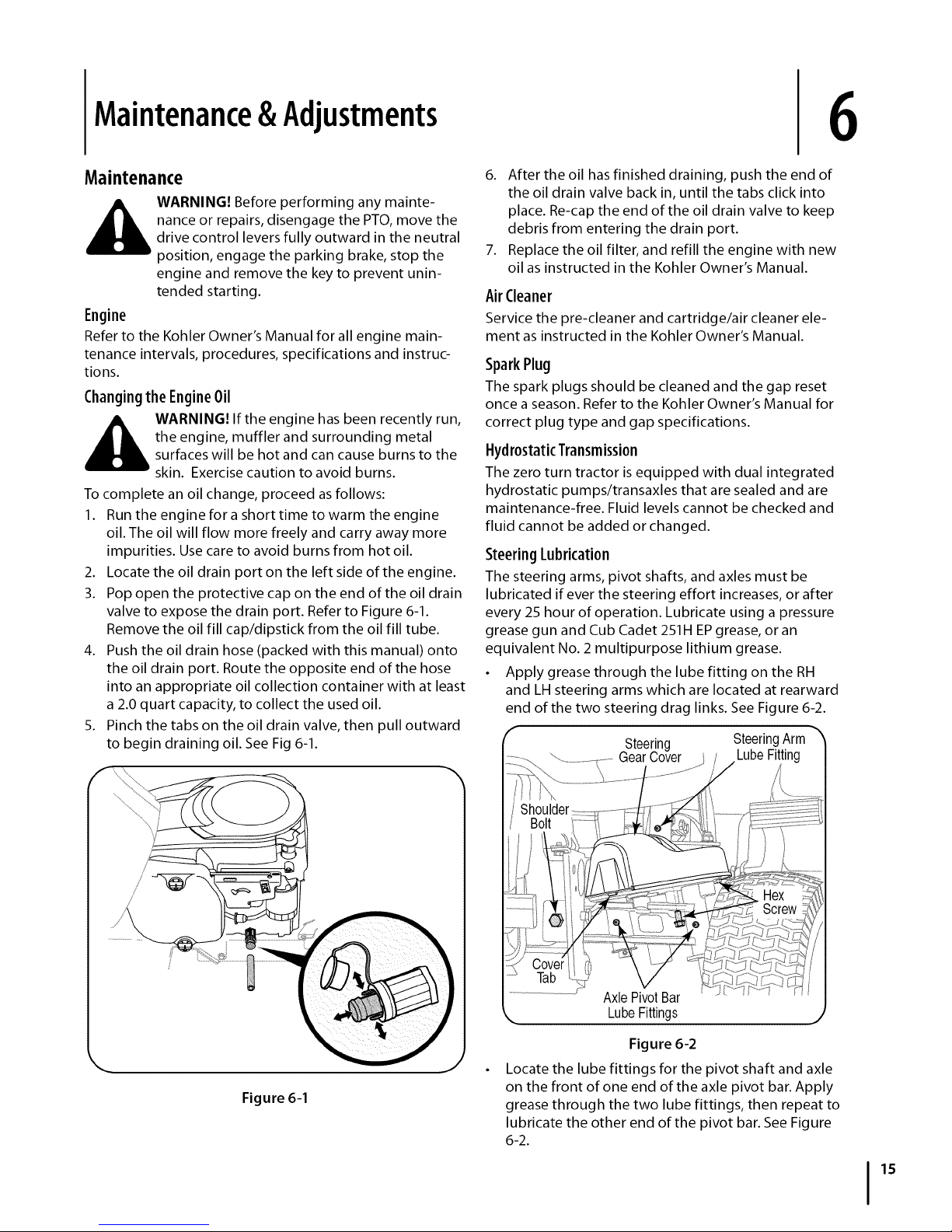
• Apply grease through the lube fitting on the RH
and LH steering arms which are located at rearward
end of the two steering drag links. See Figure 6-2.
Steering SteeringArm
GearCover LubeFitting
//
Figure6-1
Lube _gs
Figure 6-2
Locate the lube fittings for the pivot shaft and axle
on the front of one end of the axle pivot bar. Apply
grease through the two lube fittings, then repeat to
lubricate the other end of the pivot bar. See Figure
6-2.
15
Page 16
CleaningSteeringGears
Once a year, or ira tight spot is experienced when turning
the steering wheel, remove the steering gear cover on
each end of the pivot bar and clean the two steering gears.
• From beneath the cover base plate on each end of the
pivot bar, remove the three hex screws securing the
steering gear coven Remove the covers and clean the
gears. It is not necessary to lubricate the gears. Refer to
Figure 6-2.
• Insert the tab of the LH steering gear cover into the
square hole in the LH base plate, position the cover, and
secure with the three hex screws. Do not over tighten.
Repeat to install the cover on the RH side.
LubricateFrontWheel Bearings
Lubricate the front wheel bearings with Cub Cadet 251H EP
grease after every 25 hours of operation. The lube fittings
are located in the rim hub inside each front wheel.
LubricateDeckSpindlesand Idler Bracket
Lubricate the deck spindles and idler bracket with Cub
Cadet 251H EPgrease after every 10 hours of operation.
The deck spindle lube fittings are in the spindle housings,
and can only be accessed from the underside of the deck.
Lubricate the idler bracket through the lube fitting in the
top of the shoulder bolt. Use a pressure grease gun to
lubricate the spindles and idler bracket.
UsingDeckWashSystemTM
Use the Deck Wash System TM to rinse grass clippings from
the deck's underside and prevent the buildup of corrosive
chemicals. Your tractor's deck is equipped with a water
nozzle on the left end of the deck.
Complete the following steps AFTER EACH MOWING:
1. Drive the tractor to a level, clear spot on your lawn, near
enough to a water sillcock (spigot) for your garden hose
to reach.
IMPORTANT: Make certain the tractor's discharge chute is
directed AWAY from your house, garage, parked cars, etc.
2. Disengage the PTO (Blade Engage), set the parking
brake, and stop the engine.
3. Thread the nozzle adapter (packaged with your tractor's
Operator's Manual) onto the end of your garden hose.
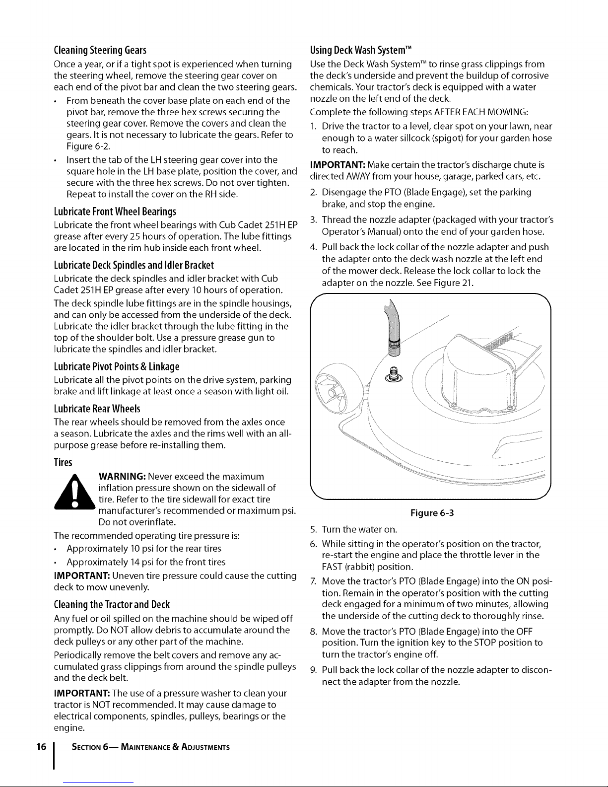
4. Pull back the lock collar of the nozzle adapter and push
the adapter onto the deck wash nozzle at the left end
of the mower deck. Release the lock collar to lock the
adapter on the nozzle. See Figure 21.
LubricatePivotPoints& Linkage
Lubricate all the pivot points on the drive system, parking
brake and lift linkage at least once a season with light oil.
LubricateRearWheels
The rear wheels should be removed from the axles once
a season. Lubricate the axles and the rims well with an all-
purpose grease before re-installing them.
Tires
WARNING: Never exceed the maximum
inflation pressure shown on the sidewall of
tire. Refer to the tire sidewall for exact tire
manufacturer's recommended or maximum psi.
Do not overinflate.
The recommended operating tire pressure is:
• Approximately 10 psi for the rear tires
• Approximately 14 psi for the front tires
IMPORTANT: Uneven tire pressure could cause the cutting
deck to mow unevenly.
CleaningtheTractorandDeck
Any fuel or oil spilled on the machine should be wiped off
promptly. Do NOT allow debris to accumulate around the
deck pulleys or any other part of the machine.
Periodically remove the belt covers and remove any ac-
cumulated grass clippings from around the spindle pulleys
and the deck belt.
IMPORTANT: The use of a pressure washer to clean your
tractor is NOT recommended. It may cause damage to
electrical components, spindles, pulleys, bearings or the
engine.
SECTION6-- MAINTENANCE _ ADJUSTMENTS
Figure 6-3
5.
Turn the water on.
6.
While sitting in the operator's position on the tractor,
re-start the engine and place the throttle lever in the
FAST (rabbit) position.
7. Move the tractor's PTO (Blade Engage) into the ON posi-
tion. Remain in the operator's position with the cutting
deck engaged fora minimum of two minutes, allowing
the underside of the cutting deck to thoroughly rinse.
8. Move the tractor's PTO (Blade Engage) into the OFF
position. Turn the ignition key to the STOP position to
turn the tractor's engine off.
9. Pull back the lock collar of the nozzle adapter to discon-
nect the adapter from the nozzle.
Page 17
MovingtheTractorManually
If for any reason the tractor will not drive or you wish to
move the tractor, engage the two hydro transmission
bypass rods to manually move the tractor short distances.
IMPORTANT: Never tow or drag the tractor with the rear
wheels on the ground. Even with the bypass rods engaged.
Doing so will damage the transmissions.
To engage a bypass rod, pull the rod rearward so that the
flange on the rod passes through the larger/rounded part
of the keyhole slot. With the flange of the rod outside
(rearward) of the hitch plate, push the rod inward in the
small part of the keyhole slot so that rod's flange is locked
against the back of the hitch plate. Repeat to engage
the other bypass rod to allow the tractor to be manually
moved. See Figure 6-4.
f
f
Adjusting the Seat
driving the tractor, make sure that the seat
_ ARNING: After adjusting the seat or before
adjustment lever is engaged in the seat index
plate and that the seat will not move. Do not
adjust the seat while the tractor is being driven.
Adjusting the seat while the tractor is moving
could cause the operator to lose control of the
tractor.
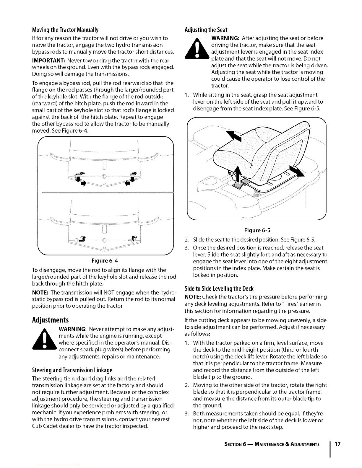
1. While sitting in the seat, grasp the seat adjustment
lever on the left side of the seat and pull it upward to
disengage from the seat index plate. See Figure 6-5.
_, ,J
Figure 6-4
To disengage, move the rod to align its flange with the
larger/rounded part of the keyhole slot and release the rod
back through the hitch plate.
NOTE: The transmission will NOT engage when the hydro-
static bypass rod is pulled out. Return the rod to its normal
position prior to operating the tractor.
Adjustments
ments while the engine is running, except
__ ARNING: Never attempt to make any adjust-
SteeringandTransmissionLinkage
The steering tie rod and drag links and the related
transmission linkage are set at the factory and should
not require further adjustment. Because of the complex
adjustment procedure, the steering and transmission
linkage should only be serviced or adjusted by a qualified
mechanic. If you experience problems with steering, or
with the hydro drive transmissions, contact your nearest
Cub Cadet dealer to have the tractor inspected.
where specified in the operator's manual. Dis-
connect spark plug wire(s) before performing
any adjustments, repairs or maintenance.
Figure 615
2.
Slide the seat to the desired position. See Figure 6-5.
3.
Once the desired position is reached, release the seat
lever. Slide the seat slightly fore and aft as necessary to
engage the seat lever into one of the eight adjustment
positions in the index plate. Make certain the seat is
locked in position.
Sideto SideLevelingthe Deck
NOTE: Check the tractor's tire pressure before performing
any deck leveling adjustments. Refer to "Tires" earlier in
this section for information regarding tire pressure,
If the cutting deck appears to be mowing unevenly, a side
to side adjustment can be performed. Adjust if necessary
as follows:
1. With the tractor parked on a firm, level surface, move
the deck to the mid height position (third or fourth
notch) using the deck lift lever. Rotate the left blade so
that it is perpendicular to the tractor frame. Measure
and record the distance from the outside of the left
blade tip to the ground.
2. Moving to the other side of the tractor, rotate the right
blade so that it is perpendicular to the tractor frame,
and measure the distance from its outer blade tip to
the ground.
3. Both measurements taken should be equal. If they're
not, note whether the left side of the deck is lower or
higher and proceed to the next step.
SECTION6 -- MAINTENANCE • ADJUSTMENTS 17
Page 18
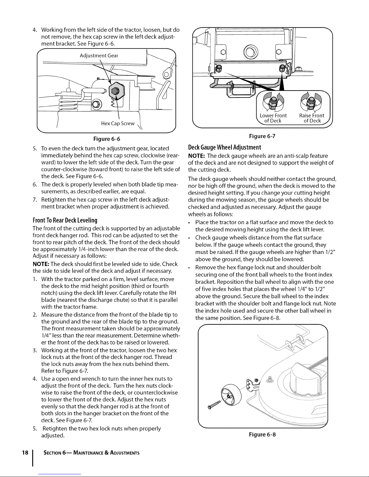
Working from the left side of the tractor, loosen, but do
not remove, the hex cap screw in the left deck adjust-
ment bracket. See Figure 6-6.
Adjustment Gear
Hex Cap Screw \
Raise Front
of Deckj
Figure 6-6
5. To even the deck turn the adjustment gear, located
immediately behind the hex cap screw, clockwise (rear-
ward) to lower the left side of the deck. Turn the gear
counter-clockwise (toward front) to raise the left side of
the deck. See Figure 6-6.
6. The deck is properly leveled when both blade tip mea-
surements, as described earlier, are equal.
7. Retighten the hex cap screw in the left deck adjust-
ment bracket when proper adjustment is achieved.
FrontToRearDeckLeveling
The front of the cutting deck is supported by an adjustable
front deck hanger rod. This rod can be adjusted to set the
front to rear pitch of the deck. The front of the deck should
be approximately 1/4-inch lower than the rear of the deck.
Adjust if necessary as follows:
NOTE: The deck should first be leveled side to side. Check
the side to side level of the deck and adjust if necessary.
1. With the tractor parked on a firm, level surface, move
the deck to the mid height position (third or fourth
notch) using the deck lift lever. Carefully rotate the RH
blade (nearest the discharge chute) so that it is parallel
with the tractor frame.
2. Measure the distance from the front of the blade tip to
the ground and the rear of the blade tip to the ground.
The front measurement taken should be approximately
1/4" less than the rear measurement. Determine wheth-
er the front of the deck has to be raised or lowered.
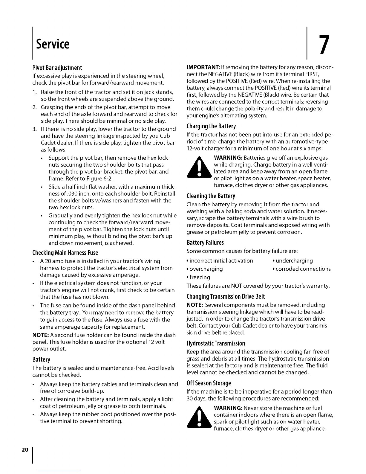
3. Working at the front of the tractor, loosen the two hex
lock nuts at the front of the deck hanger rod. Thread
the lock nuts away from the hex nuts behind them.
Refer to Figure 6-7.
4. Use a open end wrench to turn the inner hex nuts to
adjust the front of the deck. Turn the hex nuts clock-
wise to raise the front of the deck, or counterclockwise
to lower the front of the deck. Adjust the hex nuts
evenly so that the deck hanger rod is at the front of
both slots in the hanger bracket on the front of the
deck. See Figure 6-7.
5. Retighten the two hex lock nuts when properly
adjusted.
Figure 6-7
Deck GaugeWheel Adjustment
NOTE: The deck gauge wheels are an anti-scalp feature
of the deck and are not designed to support the weight of
the cutting deck.
The deck gauge wheels should neither contact the ground,
nor be high off the ground, when the deck is moved to the
desired height setting. If you change your cutting height
during the mowing season, the gauge wheels should be
checked and adjusted as necessary. Adjust the gauge
wheels as follows:
• Place the tractor on a flat surface and move the deck to
the desired mowing height using the deck lift lever.
• Check gauge wheels distance from the flat surface
below. If the gauge wheels contact the ground, they
must be raised. If the gauge wheels are higher than 1/2"
above the ground, they should be lowered.
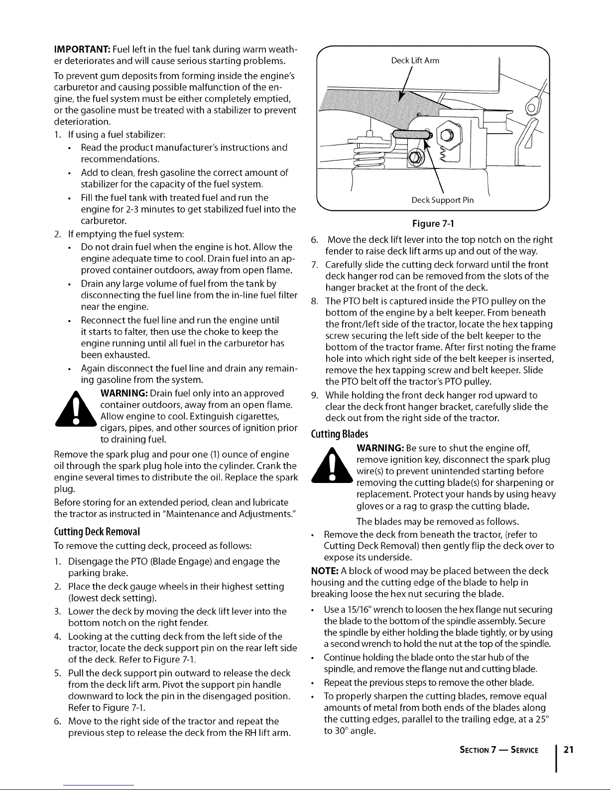
• Remove the hex flange lock nut and shoulder bolt
securing one of the front ball wheels to the front index
bracket. Reposition the ball wheel to align with the one
of five index holes that places the wheel 1/4" to 1/2"
above the ground. Secure the ball wheel to the index
bracket with the shoulder bolt and flange lock nut. Note
the index hole used and secure the other ball wheel in
the same position. See Figure 6-8.
f
Figure 6-8
SECTION6-- MAINTENANCE _ ADJUSTMENTS
Page 19

Maintenance Schedule
Before
Eachuse
CleanHood/DashLouvers
CheckEngineOilLevel
CheckAirFilterforDirty,LooseorDamagedParts
CleanandRe-oilAirFilter'sFoamPrecleaner
ReplaceAirFilterElement
ChangeEngineOilandReplaceOilFilter
CleanBatteryTerminals _
LubeMidSteeringArms,PivotShafts,andAxles Y'" Y'"
LubeFrontWheelBearings Y'" Y'"
CleanEngineCoolingFins Y'" Y'"
Every
10Hours
Every
25Hours
Every
SOHours
Every
100Hours
Prior
toStoring
LubeFrontDeckWheels Y'" Y'"
LubeDeckSpindlesandIdlerBracket Y'" Y'"
LubePedalPivotPoints
CheckSparkPlugCondition& Gap Y'" Y'"
ReplaceFuelFilter
SECTION6 -- MAINTENANCE • ADJUSTMENTS 19
Page 20
Service
7
Pivot Baradjustment
If excessive play is experienced in the steering wheel,
check the pivot bar for forward/rearward movement.
1. Raise the front of the tractor and set it on jack stands,
so the front wheels are suspended above the ground.
2. Grasping the ends of the pivot bar, attempt to move
each end of the axle forward and rearward to check for
side play. There should be minimal or no side play.
3. If there is no side play, lower the tractor to the ground
and have the steering linkage inspected by you Cub
Cadet dealer. If there is side play, tighten the pivot bar
as follows:
• Support the pivot bar, then remove the hex lock
nuts securing the two shoulder bolts that pass
through the pivot bar bracket, the pivot bar, and
frame. Refer to Figure 6-2.
• Slide a half inch flat washer, with a maximum thick-
ness of .030 inch, onto each shoulder bolt. Reinstall
the shoulder bolts w/washers and fasten with the
two hex lock nuts.
• Gradually and evenly tighten the hex lock nut while
continuing to check the forward/rearward move-
ment of the pivot bar. Tighten the lock nuts until
minimum play, without binding the pivot bar's up
and down movement, is achieved.
CheckingMain HarnessFuse
• A 20 amp fuse is installed in your tractor's wiring
harness to protect the tractor's electrical system from
damage caused by excessive amperage.
• If the electrical system does not function, or your
tractor's engine will not crank, first check to be certain
that the fuse has not blown.
• The fuse can be found inside of the dash panel behind
the battery tray. You may need to remove the battery
to gain access to the fuse. Always use a fuse with the
same amperage capacity for replacement.
NOTE: A second fuse holder can be found inside the dash
panel. This fuse holder is used for the optional 12 volt
power outlet.
Battery
The battery is sealed and is maintenance-free. Acid levels
cannot be checked.
• Always keep the battery cables and terminals clean and
free of corrosive build-up.
• After cleaning the battery and terminals, apply a light
coat of petroleum jelly or grease to both terminals.
• Always keep the rubber boot positioned over the posi-
tive terminal to prevent shorting.
IMPORTANT: If removing the battery for any reason, discon-
nect the NEGATIVE (Black) wire from it's terminal FIRST,
followed by the POSITIVE (Red) wire. When re-installing the
battery, always connect the POSITIVE (Red) wire its terminal
first, followed by the NEGATIVE (Black) wire. Be certain that
the wires are connected to the correct terminals; reversing
them could change the polarity and result in damage to
your engine's alternating system.
Chargingthe Battery
If the tractor has not been put into use for an extended pe-
riod of time, charge the battery with an automotive-type
12-volt charger for a minimum of one hour at six amps.
WARNING: Batteries give off an explosive gas
while charging. Charge battery in a well venti-
lated area and keep away from an open flame
or pilot light as on a water heater, space heater,
furnace, clothes dryer or other gas appliances.
Cleaningthe Battery
Clean the battery by removing it from the tractor and
washing with a baking soda and water solution. If neces-
sary, scrape the battery terminals with a wire brush to
remove deposits. Coat terminals and exposed wiring with
grease or petroleum jelly to prevent corrosion.
BatteryFailures
Some common causes for battery failure are:
• incorrect initial activation • undercharging
• overcharging • corroded connections
• freezing
These failures are NOT covered by your tractor's warranty.
ChangingTransmissionDriveBelt
NOTE: Several components must be removed, including
transmission steering linkage which will have to be read-
justed, in order to change the tractor's transmission drive
belt. Contact your Cub Cadet dealer to have your transmis-
sion drive belt replaced.
HydrostaticTransmission
Keep the area around the transmission cooling fan free of
grass and debris at all times. The hydrostatic transmission
is sealed at the factory and is maintenance free. The fluid
level cannot be checked and cannot be changed.
OffSeasonStorage
If the machine is to be inoperative for a period longer than
30 days, the following procedures are recommended:
WARNING: Never store the machine or fuel
container indoors where there is an open flame,
spark or pilot light such as on water heater,
furnace, clothes dryer or other gas appliance.
Page 21
IMPORTANT: Fuel left in the fuel tank during warm weath-
er deteriorates and will cause serious starting problems.
To prevent gum deposits from forming inside the engine's
carburetor and causing possible malfunction of the en-
gine, the fuel system must be either completely emptied,
or the gasoline must be treated with a stabilizer to prevent
deterioration.
1. If using a fuel stabilizer:
• Read the product manufacturer's instructions and
recommendations.
• Add to clean, fresh gasoline the correct amount of
stabilizer for the capacity of the fuel system.
• Fill the fuel tank with treated fuel and run the
engine for 2-3 minutes to get stabilized fuel into the
carburetor.
2. If emptying the fuel system:
• Do not drain fuel when the engine is hot. Allow the
engine adequate time to cool. Drain fuel into an ap-
proved container outdoors, away from open flame.
• Drain any large volume of fuel from the tank by
disconnecting the fuel line from the in-line fuel filter
near the engine.
• Reconnect the fuel line and run the engine until
it starts to falter, then use the choke to keep the
engine running until all fuel in the carburetor has
been exhausted.
• Again disconnect the fuel line and drain any remain-
ing gasoline from the system.
container outdoors, away from an open flame.
_ WARNING: Drain fuel only into an approved
Allow engine to cool. Extinguish cigarettes,
cigars, pipes, and other sources of ignition prior
to draining fuel.
Remove the spark plug and pour one (1)ounce of engine
oil through the spark plug hole into the cylinder. Crank the
engine several times to distribute the oil. Replace the spark
plug.
Before storing for an extended period, clean and lubricate
the tractor as instructed in "Maintenance and Adjustments."
CuttingDeckRemoval
To remove the cutting deck, proceed as follows:
1. Disengage the PTO (Blade Engage) and engage the
parking brake.
2. Place the deck gauge wheels in their highest setting
(lowest deck setting).
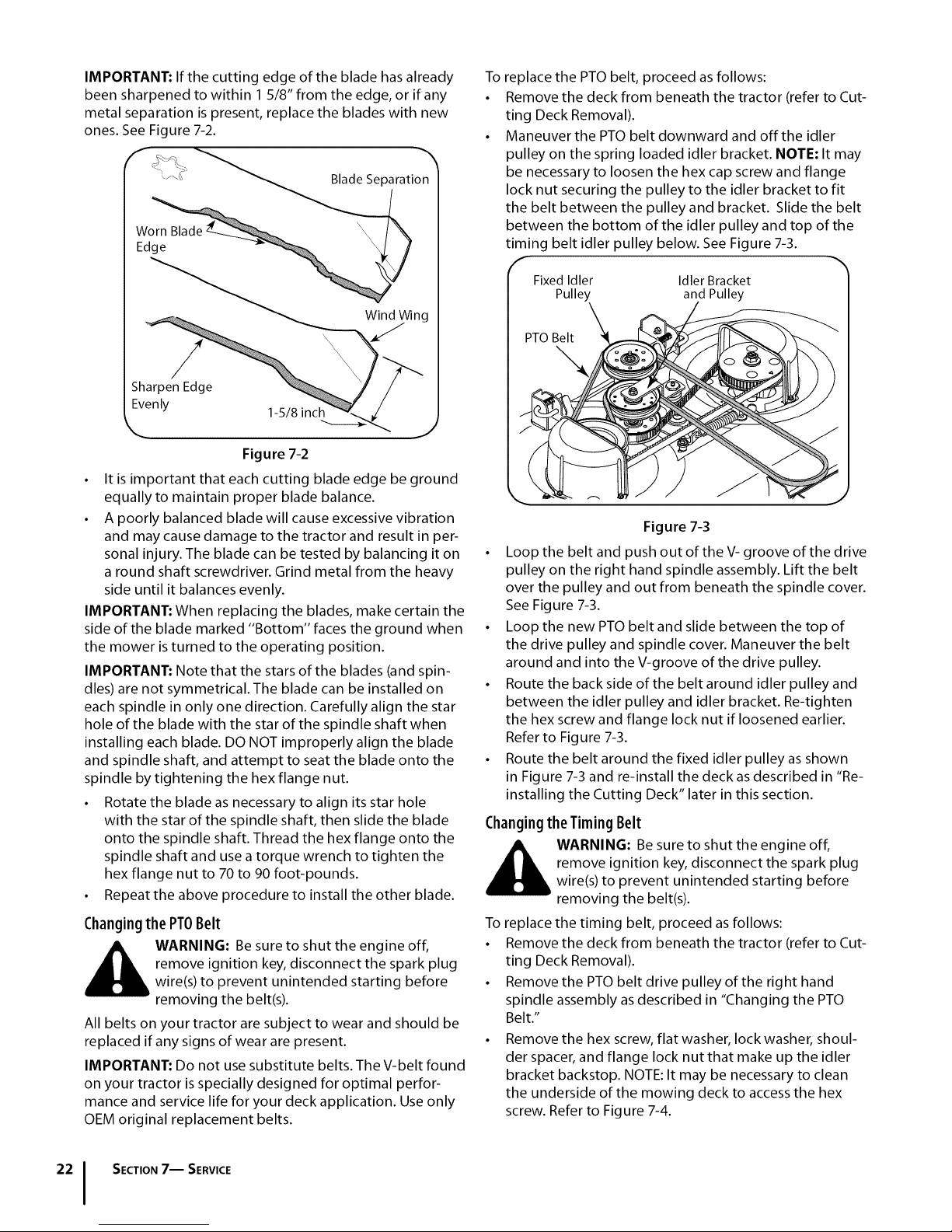
3. Lower the deck by moving the deck lift lever into the
bottom notch on the right fender.
4. Looking at the cutting deck from the left side of the
tractor, locate the deck support pin on the rear left side
of the deck. Refer to Figure 7-1.
5. Pull the deck support pin outward to release the deck
from the deck lift arm. Pivot the support pin handle
downward to lock the pin in the disengaged position.
Refer to Figure 7-1.
6. Move to the right side of the tractor and repeat the
previous step to release the deck from the RH lift arm.
f
Deck Lift Arm
k Deck Support Pin
J
Figure 7-1
6. Move the deck lift lever into the top notch on the right
fender to raise deck lift arms up and out of the way.
7. Carefully slide the cutting deck forward until the front
deck hanger rod can be removed from the slots of the
hanger bracket at the front of the deck.
8. The PTO belt is captured inside the PTO pulley on the
bottom of the engine by a belt keeper. From beneath
the front/left side of the tractor, locate the hex tapping
screw securing the left side of the belt keeper to the
bottom of the tractor frame. After first noting the frame
hole into which right side of the belt keeper is inserted,
remove the hex tapping screw and belt keeper. Slide
the PTO belt off the tractor's PTO pulley.
9. While holding the front deck hanger rod upward to
clear the deck front hanger bracket, carefully slide the
deck out from the right side of the tractor.
Cutting Blades
remove ignition key, disconnect the spark plug
_ ARNING: Be sure to shut the engine off,
• Remove the deck from beneath the tractor, (refer to
Cutting Deck Removal) then gently flip the deck over to
expose its underside.
NOTE: A block of wood may be placed between the deck
housing and the cutting edge of the blade to help in
breaking loose the hex nut securing the blade.
• Use a 15/16" wrench to loosen the hex flange nut securing
the blade to the bottom of the spindle assembly. Secure
the spindle by either holding the blade tightly, or by using
asecond wrench to hold the nut at the top of the spindle.
• Continue holding the blade onto the star hub of the
spindle, and remove the flange nut and cutting blade.
• Repeat the previous steps to remove the other blade.
• To properly sharpen the cutting blades, remove equal
amounts of metal from both ends of the blades along
the cutting edges, parallel to the trailing edge, at a 25°
to 30° angle.
wire(s) to prevent unintended starting before
removing the cutting blade(s) for sharpening or
replacement. Protect your hands by using heavy
gloves or a rag to grasp the cutting blade.
The blades may be removed as follows.
SECTION7 -- SERVICE 21
Page 22
IMPORTANT:If the cutting edge of the blade has already
been sharpened to within 15/8" from the edge, or if any
metal separation is present, replace the blades with new
ones See Figure 7-2
BladeSeparation
Worn Blade
Edge
Wind Wing
Sharpen Edge
Evenly
_ J
• It is important that each cutting blade edge be ground
equally to maintain proper blade balance
• A poorly balanced blade will cause excessive vibration
and may cause damage to the tractor and result in per-
sonal injury The blade can be tested by balancing it on
a round shaft screwdriver Grind metal from the heavy
side until it balances evenly
IMPORTANT: When replacing the blades, make certain the
side of the blade marked "Bottom" faces the ground when
the mower is turned to the operating position
IMPORTANT: Note that the stars of the blades (and spin-
dles) are not symmetrical The blade can be installed on
each spindle in only one direction Carefully align the star
hole of the blade with the star of the spindle shaft when
installing each blade DO NOT improperly align the blade
and spindle shaft, and attempt to seat the blade onto the
spindle by tightening the hex flange nut
• Rotate the blade as necessary to align its star hole
with the star of the spindle shaft, then slide the blade
onto the spindle shaft Thread the hex flange onto the
spindle shaft and use a torque wrench to tighten the
hex flange nut to 70 to 90 foot-pounds
• Repeat the above procedure to install the other blade
Changingthe PT0Belt
_ ARNING: Be sure to shut the engine off,
All belts on your tractor are subject to wear and should be
replaced if any signs of wear are present
IMPORTANT: Do not use substitute belts The V-belt found
on your tractor is specially designed for optimal perfor
mance and service life for your deck application Use only
OEM original replacement belts
remove ignition key, disconnect the spark plug
wire(s) to prevent unintended starting before
removing the belt(s)
15/8 inch
Figure 7-2
To
replace the PTO belt, proceed as follows:
Remove the deck from beneath the tractor (refer to Cut-
ting Deck Removal)
Maneuver the PTO belt downward and off the idler
pulley on the spring loaded idler bracket NOTE: It may
be necessary to loosen the hex cap screw and flange
lock nut securing the pulley to the idler bracket to fit
the belt between the pulleyand bracket Slide the belt
between the bottom of the idler pulley and top of the
timing belt idler pulley below See Figure 7-3
Fixed Idler Idler Bracket
Pulley and Pulley
\
Figure 7-3
• Loop the belt and push out of the V- groove of the drive
pulley on the right hand spindle assembly Lift the belt
over the pulley and out from beneath the spindle cover
See Figure 7-3
• Loop the new PTO belt and slide between the top of
the drive pulley and spindle cover Maneuver the belt
around and into the V-groove of the drive pulley
• Route the back side of the belt around idler pulley and
between the idler pulley and idler bracket Re-tighten
the hex screw and flange lock nut if loosened earlier
Refer to Figure 7-3
• Route the belt around the fixed idler pulley as shown
in Figure 7-3 and re-install the deck as described in "Re-
installing the Cutting Deck" later in this section
Changingthe TimingBelt
_ ARNING: Be sure to shut the engine off,
To replace the timing belt, proceed as follows:
• Remove the deck from beneath the tractor (refer to Cut-
ting Deck Removal).
• Remove the PTO belt drive pulley of the right hand
spindle assembly asdescribed in "Changing the PTO
Belt."
• Remove the hex screw, flat washer, lock washer, shoul-
der spacer, and flange lock nut that make up the idler
bracket backstop. NOTE: It may be necessary to clean
the underside of the mowing deck to access the hex
screw. Refer to Figure 7-4.
remove ignition key, disconnect the spark plug
wire(s) to prevent unintended starting before
removing the belt(s).
SECTION7-- SERVICE
Page 23
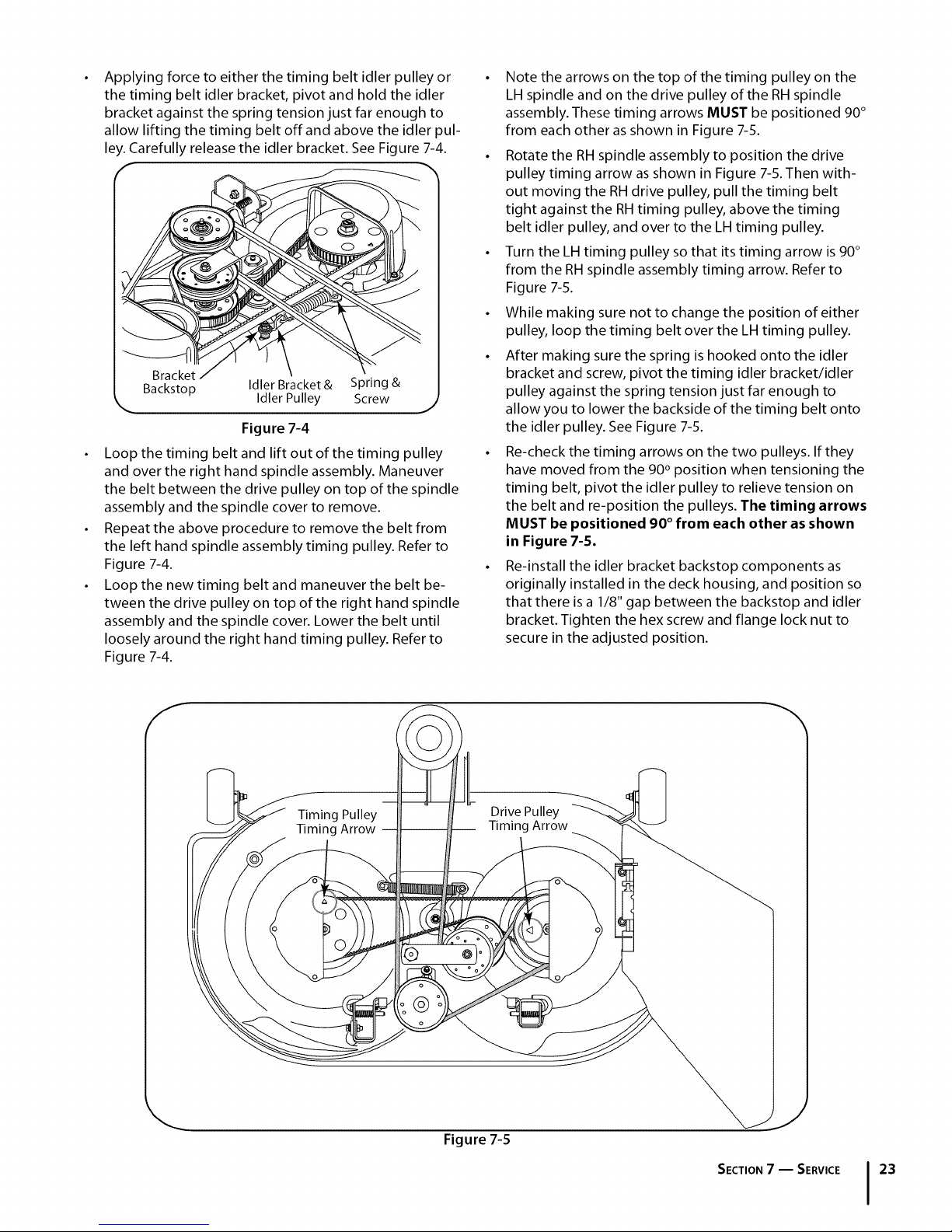
Applying force to either the timing belt idler pulley or
the timing belt idler bracket, pivot and hold the idler
bracket against the spring tension just far enough to
allow lifting the timing belt off and above the idler pul-
ley Carefully release the idler bracket See Figure 7-4
F
Backstop Idler Bracket & Spring &
_. Idler Pulley Screw J
Figure 7-4
Loop the timing belt and lift out of the timing pulley
and over the right hand spindle assembly Maneuver
the belt between the drive pulley on top of the spindle
assembly and the spindle cover to remove
Repeat the above procedure to remove the belt from
the left hand spindle assembly timing pulley Refer to
Figure 7-4
Loop the new timing belt and maneuver the belt be-
tween the drive pulley on top of the right hand spindle
assembly and the spindle cover Lower the belt until
loosely around the right hand timing pulley Refer to
Figure 7-4
• Note the arrows on the top of the timing pulley on the
LH spindle and on the drive pulley of the RH spindle
assembly These timing arrows MUST be positioned 90°
from each other as shown in Figure 7-5
• Rotate the RHspindle assembly to position the drive
pulley timing arrow as shown in Figure 7-5 Then with-
out moving the RH drive pulley, pull the timing belt
tight against the RHtiming pulley, above the timing
belt idler pulley, and over to the LH timing pulley
• Turn the LH timing pulley so that its timing arrow is 90°
from the RH spindle assembly timing arrow Refer to
Figure 7-5
• While making sure not to change the position of either
pulley, loop the timing belt over the LH timing pulley
• After making sure the spring is hooked onto the idler
bracket and screw, pivot the timing idler bracket/idler
pulley against the spring tension just far enough to
allow you to lower the backside of the timing belt onto
the idler pulley See Figure 7-5
• Re-check the timing arrows on the two pulleys If they
have moved from the 90° position when tensioning the
timing belt, pivot the idler pulley to relieve tension on
the belt and re-position the pulleys The timing arrows
MUST be positioned 90 ° from each other as shown
in Figure 7-5.
• Re-install the idler bracket backstop components as
originally installed in the deck housing, and position so
that there is a 1/8" gap between the backstop and idler
bracket Tighten the hex screw and flange lock nut to
secure in the adjusted position
Timing Pulley
Timing Arrow
Drive Pulley
Timing Arrow
@
Figure 7-5
SECTION7 -- SERVICE 23
Page 24
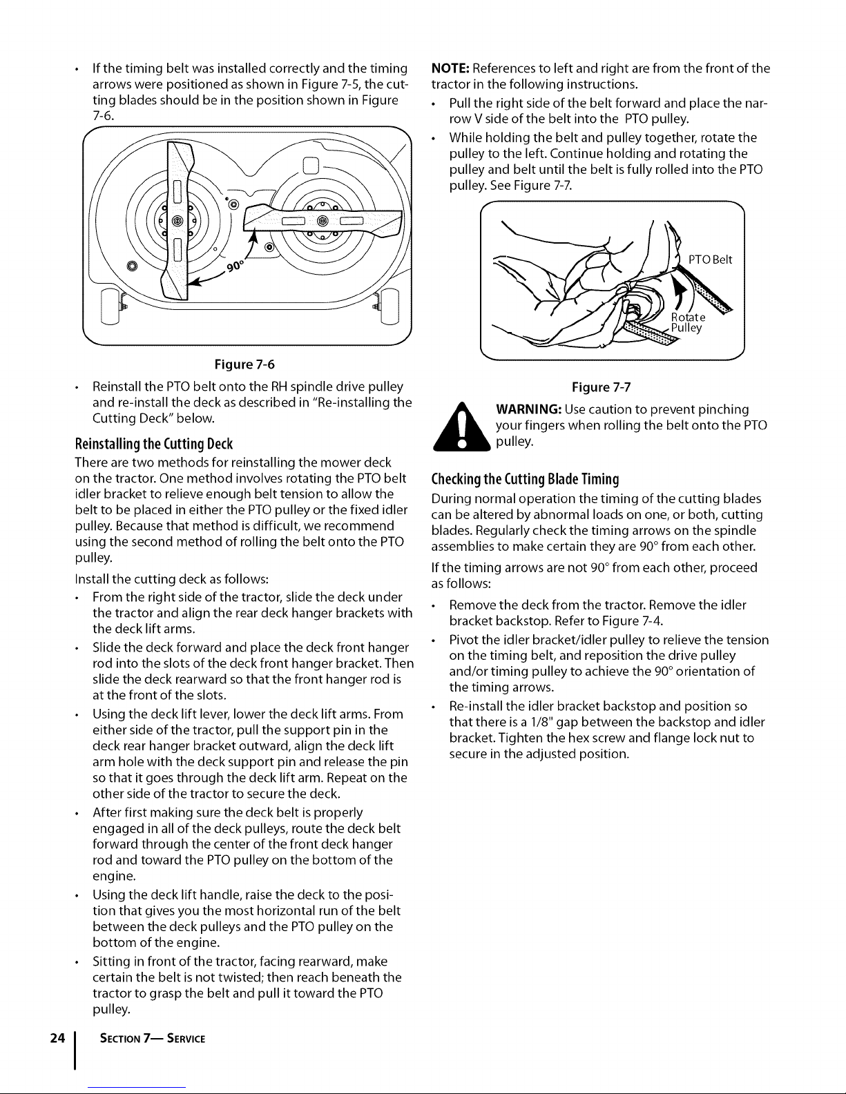
If the timing belt was installed correctly and the timing
arrows were positioned as shown in Figure 7-5, the cut-
ting blades should be in the position shown in Figure
7-6.
f
Figure 7-6
Reinstall the PTO belt onto the RH spindle drive pulley
and re-install the deck as described in "Re-installing the
Cutting Deck" below.
ReinstallingtheCutting Deck
There are two methods for reinstalling the mower deck
on the tractor. One method involves rotating the PTO belt
idler bracket to relieve enough belt tension to allow the
belt to be placed in either the PTO pulley or the fixed idler
pulley. Because that method is difficult, we recommend
using the second method of rolling the belt onto the PTO
pulley.
Install the cutting deck as follows:
• From the right side of the tractor, slide the deck under
the tractor and align the rear deck hanger brackets with
the deck lift arms.
• Slide the deck forward and place the deck front hanger
rod into the slots of the deck front hanger bracket. Then
slide the deck rearward so that the front hanger rod is
at the front of the slots.
• Using the deck lift lever, lower the deck lift arms. From
either side of the tractor, pull the support pin in the
deck rear hanger bracket outward, align the deck lift
arm hole with the deck support pin and release the pin
so that it goes through the deck lift arm. Repeat on the
other side of the tractor to secure the deck.
• After first making sure the deck belt is properly
engaged in all of the deck pulleys, route the deck belt
forward through the center of the front deck hanger
rod and toward the PTO pulley on the bottom of the
engine.
• Using the deck lift handle, raise the deck to the posi-
tion that gives you the most horizontal run of the belt
between the deck pulleys and the PTO pulley on the
bottom of the engine.
• Sitting in front of the tractor, facing rearward, make
certain the belt is not twisted; then reach beneath the
tractor to grasp the belt and pull it toward the PTO
pulley.
NOTE: References to left and right are from the front of the
tractor in the following instructions.
• Pull the right side of the belt forward and place the nar-
row V side of the belt into the PTO pulley.
• While holding the belt and pulley together, rotate the
pulley to the left. Continue holding and rotating the
pulley and belt until the belt is fully rolled into the PTO
pulley. See Figure 7-7.
PTOBelt
Pulley
Figure 7-7
_ ARNING: Use caution to prevent pinching
your fingers when rolling the belt onto the PTO
pulley.
Checkingthe CuttingBladeTiming
During normal operation the timing of the cutting blades
can be altered by abnormal loads on one, or both, cutting
blades. Regularly check the timing arrows on the spindle
assemblies to make certain they are 90 ° from each other.
If the timing arrows are not 90° from each other, proceed
as follows:
• Remove the deck from the tractor. Remove the idler
bracket backstop. Refer to Figure 7-4.
• Pivot the idler bracket/idler pulley to relieve the tension
on the timing belt, and reposition the drive pulley
and/or timing pulley to achieve the 90 ° orientation of
the timing arrows.
• Re-install the idler bracket backstop and position so
that there is a 1/8" gap between the backstop and idler
bracket. Tighten the hex screw and flange lock nut to
secure in the adjusted position.
SECTION7-- SERVICE
Page 25

Troubleshooting
8
Problem Cause
Engine runs erratic
1. Unit running with CHOKE activated.
2. Spark plug wire(s) loose.
3. Blocked fuel line or stale fuel.
4. Ventin gas cap plugged.
5. Water or dirt in fuel system.
6. Dirty air cleaner.
I
1. Push CHOKE control in.
2. Connect spark plug wire(s).
3. Clean fuel line; fill tank with clean, fresh
gasoline and replace fuel filter.
4. Clearvent or replace cap if damaged.
5. Drain fuel tank. Refill with clean, fresh
gasoline.
6. Replace air cleaner paper element or clean
foam precleaner.
Remedy
Engine hesitates at high
RPM
Excessive vibration
Uneven cut
1. Spark plug(s) gap too close.
1. Cutting blade loose or unbalanced.
2. Damaged or bent cutting blade.
1. Deck not leveled properly.
2. Dull blade.
3. Uneven tire pressure.
1. Remove spark plug(s) and resetthe gap.
1. Tighten blade and spindle.
2. Replace blade.
1. Perform side-to-side deck adjustment.
2. Sharpen or replace blade.
3. Check tire pressure in all four tires.
25
Page 26

ReplacementParts
Contact your Cub Cadet dealer to order replacement parts. If you do not have a dealer, call the Customer Dealer Referral Line at 1-877-
282-8684 or visit www.cubcadet.com to find the nearest Cub Cadet dealer in your area. Phone (800) 965-4CUB to order replacement
parts or a complete Parts Manual (have your full model number and serial number ready). Parts Manual downloads are also available
free of charge at www.cubcadet.com.
Changingthe TimingBelt Model i1042
Lower Drive Belt _Contact Dealer 954-04134
Engine to Deck/PTO Belt 954-04185
Deck Timing Belt 954-04167
Blades 942-04217 (Qty. 2)
Deck Spindle - Right Hand 618-04512
Deck Spindle - Left Hand 618-04516
Deck Front Ball Wheels 734-04155 (Qty. 2)
Battery 925-1707D
Starter Solenoid 725-04439
Ignition Keys 725-2054A
Engine Oil Filter KH-52-050-02
Engine Oil (Capacity 57.6 ounces) 737-3030A (lqt.)
Engine Air Filter Element KH-32-083-03-S
Engine Air Filter Foam Precleaner Element KH-32-083-05-S
Fuel Filter KH-25-050-22-S
Spark Plug 759-3336
Deck Discharge Chute Assembly 631-04254
9
Attachments& Accessories
MODEL ' DESCRIPTION
19A70001000
19A70002000
190-833-000
19Aq02-100
19A-106-100
19Aq05-100
19A-103-100
19Aq04-100
19A-107-100
19Aq13-i00
19A-108-100
19A-109-100
TwinRearBaggerGrassCollectorfor46" Deck
MulchingKit
46"DozerBlade
18CubicFootSteelCart
10CubicFootPolyCart
48"BroadcastSpreader ..............
42"Sweeper
25 GallonSprayer
48"Dethatcher
48"PolyRoller
48"PlugAerator
48"SpikeAerator ................
Page 27
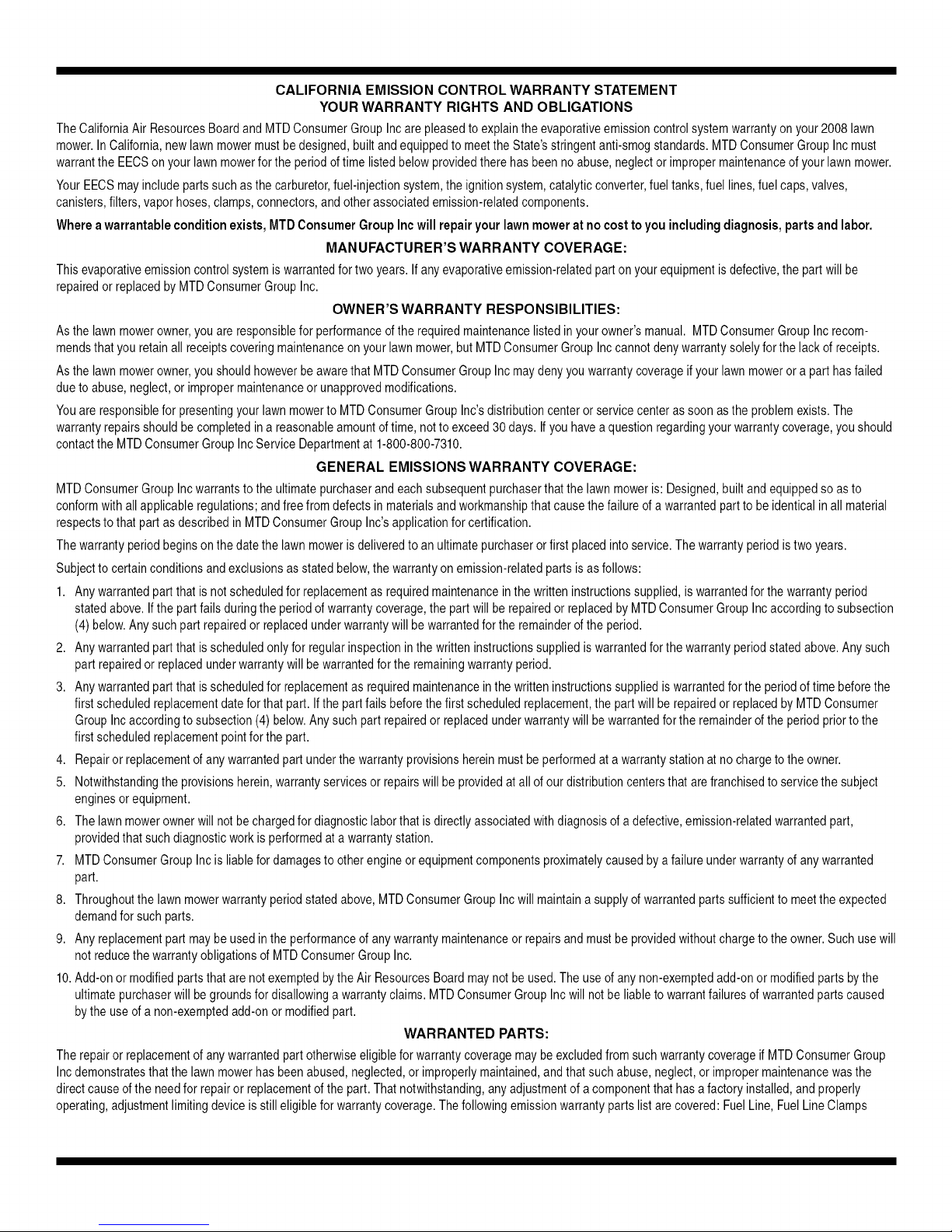
CALIFORNIA EMISSION CONTROL WARRANTY STATEMENT
YOUR WARRANTY RIGHTS AND OBLIGATIONS
TheCaliforniaAirResourcesBoardandMTDConsumerGroupIncare pleasedtoexplaintheevaporativeemissioncontrolsystemwarrantyonyour2008 lawn
mower.InCalifornia,newlawnmowermustbe designed,builtand equippedto meettheState'sstringentanti-smogstandards.MTDConsumerGroupIncmust
warrantthe EECSonyourlawnmowerforthe periodoftime listedbelow providedthere hasbeenno abuse,neglectorimpropermaintenanceofyour lawnmower.
YourEECSmayincludeparts suchasthecarburetor,fuel-injectionsystem,the ignitionsystem,catalyticconverter,fueltanks,fuel lines,fuelcaps,valves,
canisters,filters,vaporhoses,clamps,connectors,andotherassociatedemission-relatedcomponents.
Wherea warrantable condition exists, MTDConsumer Group Inc will repair your lawn mower at no cost to you including diagnosis, parts and labor.
MANUFACTURER'S WARRANTY COVERAGE:
Thisevaporativeemissioncontrolsystemiswarrantedfortwo years.If anyevaporativeemission-relatedparton yourequipmentisdefective,the partwill be
repairedorreplacedbyMTDConsumerGroupInc.
OWNER'S WARRANTY RESPONSIBILITIES:
Asthe lawnmowerowner,youare responsiblefor performanceoftherequiredmaintenancelistedin yourowner'smanual. MTDConsumerGroupIncrecom-
mendsthatyou retainall receiptscoveringmaintenanceonyour lawnmower,butMTDConsumerGroup Inccannotdenywarrantysolelyforthe lack of receipts.
Asthe lawnmowerowner,youshouldhoweverbeawarethatMTDConsumerGroupIncmaydeny youwarrantycoverageifyour lawnmowerora parthas failed
dueto abuse,neglect,orimpropermaintenanceorunapprovedmodifications.
Youare responsibleforpresentingyourlawn mowertoMTDConsumerGroupInc'sdistributioncenterorservicecenterassoonas the problemexists.The
warrantyrepairsshouldbecompletedin a reasonableamountoftime, nottoexceed30 days.If youhaveaquestionregardingyourwarrantycoverage,youshould
contactthe MTDConsumerGroupIncServiceDepartmentat 1-800-800-7310.
GENERAL EMISSIONS WARRANTY COVERAGE:
MTDConsumerGroupIncwarrantstothe ultimatepurchaserandeachsubsequentpurchaserthatthe lawnmoweris:Designed,built andequippedsoas to
conformwithall applicableregulations;andfreefrom defectsinmaterialsandworkmanshipthat causethe failureofa warrantedpartto beidenticalin allmaterial
respectstothat partasdescribedin MTDConsumerGroupInc'sapplicationfor certification.
Thewarrantyperiodbeginsonthedatethe lawnmoweris deliveredtoan ultimatepurchaserorfirst placedintoservice.Thewarrantyperiodistwo years.
Subjecttocertainconditionsand exclusionsasstatedbelow,thewarrantyonemission-relatedpartsis asfollows:
1. Anywarrantedpartthat isnotscheduledfor replacementasrequiredmaintenanceinthe writteninstructionssupplied,is warrantedforthewarrantyperiod
statedabove.Ifthepart fails duringtheperiodof warrantycoverage,the partwillbe repairedor replacedby MTDConsumerGroupIncaccordingto subsection
(4)below.Anysuchpart repairedorreplacedunderwarrantywillbe warrantedfor the remainderofthe period.
2. Anywarrantedpartthat isscheduledonlyfor regularinspectioninthewritteninstructionssuppliediswarrantedforthewarrantyperiodstatedabove.Any such
partrepairedor replacedunderwarrantywill bewarrantedforthe remainingwarrantyperiod.
3. Anywarrantedpartthat isscheduledforreplacementas requiredmaintenancein thewritten instructionssuppliediswarrantedforthe periodoftime beforethe
firstscheduledreplacementdatefor thatpart.If the partfails beforethefirstscheduledreplacement,the partwillbe repairedor replacedby MTDConsumer
GroupIncaccordingto subsection(4)below.Anysuch partrepairedor replacedunderwarrantywillbewarrantedforthe remainderof the periodpriortothe
firstscheduledreplacementpointfor the part.
4. Repairorreplacementofanywarrantedpart underthewarrantyprovisionshereinmustbeperformedatawarrantystationatno chargeto theowner.
5. Notwithstandingthe provisionsherein,warrantyservicesorrepairswill beprovidedatall of ourdistributioncentersthat arefranchisedto servicethe subject
enginesor equipment.
6. Thelawnmowerownerwillnot bechargedfor diagnosticlaborthat is directlyassociatedwithdiagnosisofa defective,emission-relatedwarrantedpart,
providedthat suchdiagnosticworkis performedata warrantystation.
7. MTDConsumerGroupIncisliablefordamagesto otherengineorequipmentcomponentsproximatelycausedby a failureunderwarrantyofanywarranted
part.
8. Throughoutthelawnmowerwarrantyperiodstatedabove,MTDConsumerGroupIncwill maintaina supplyof warrantedpartssufficientto meettheexpected
demandfor suchparts.
9. Anyreplacementpartmaybe usedinthe performanceof anywarrantymaintenanceorrepairsand mustbe providedwithoutchargetothe owner.Suchusewill
notreducethe warrantyobligationsofMTDConsumerGroupInc.
10.Add-onor modifiedpartsthat arenotexemptedbytheAir ResourcesBoardmaynotbe used.Theuseof any non-exemptedadd-onor modifiedpartsbythe
ultimatepurchaserwillbegroundsfor disallowinga warrantyclaims.MTDConsumerGroup Incwill notbe liableto warrantfailuresof warrantedpartscaused
bythe use ofa non-exemptedadd-onor modifiedpart.
WARRANTED PARTS:
Therepairorreplacementofanywarrantedpart otherwiseeligibleforwarrantycoveragemaybeexcludedfromsuchwarrantycoverageifMTDConsumerGroup
Incdemonstratesthat the lawnmowerhasbeenabused,neglected,orimproperlymaintained,andthat suchabuse,neglect,or impropermaintenancewasthe
directcauseofthe needfor repairor replacementof the part.Thatnotwithstanding,anyadjustmentof acomponentthathas afactory installed,and properly
operating,adjustmentlimitingdeviceisstill eligibleforwarrantycoverage.Thefollowingemissionwarrantypartslistarecovered:FuelLine,FuelLineClamps
Page 28
CUB CADET LLC
MANUFACTURER'S LIMITED WARRANTY FOR
SERIES 1000 & SERIES 1500 TRACTORS
IMPORTANT: To obtain warranty coverage owner must present an
original proof of purchase and applicable maintenance records to the
servicing dealer. Pleaseseethe operator's manual for information on
required maintenance and service intervals.
The limited warranty set forth below is given by Cub Cadet LLC with
respect to new merchandise purchased or leasedand used in the United
States and/or its territories and possessions, and by MTD Products
Limited with respect to new merchandise purchased or leased and
used in Canadaand/or its territories and possessions (either entity
respectively, "Cub Cadet").
CubCadet warrants this product (excluding its NormalWearParts,
Batteries,Frameand FrontAxleandAttachmentsas described below)
against defects in material and workmanship for a period of three (3)
years or one hundred twenty (120) operation hours, whichever comes
first, commencing on the dateof original retail purchase or lease and
will, at its option, repair or replace,free of charge, any part found to be
defective in materials or workmanship.
NormalWearPartsare warranted to befree from defects in material and
workmanship for a period ofthirty (30) days from the date of original
purchase or lease. Normal wear parts include, but are not limited to
items such as: belts, blades, bladeadapters, grass bags, rider deck
wheels, seats, andtires.
Batterieshavea one-year prorated limited warranty against defects in
material and workmanship, with 100% replacement during the first three
months. After three months, the battery replacement credit is based on
the months remaining in the twelve (12) month period dating back to the
original date of original sale or lease.Any replacement battery will be
warranted only for the remainder of the original warranty period.
FrameandFrontAxle--Cub Cadet warrants the frame, and front cast iron
pivot axle against defects in material and workmanship for a period of
five (5) years or 500 hours, whichever occurs first, commencing onthe
date of original purchase or lease.
Attachments--Cub Cadetwarrants attachments for this product against
defects in material and workmanship for aperiod of two (2) years,
commencing on the date of the attachment's original purchase or
lease.Attachments include, but are not limited to items such as: grass
collectors and mulch kits.
This limited warranty shall only apply if this product hasbeen operated
and maintained in accordance with the Operator's Manual furnished
with the product, and has not been subject to misuse, abuse, neglect,
accident, improper maintenance, alteration, vandalism, theft, fire, water,
or damage because of other peril or natural disaster. Damageresulting
from the installation or useof any part, accessory or attachment not
approved by Cub Cadetfor usewith the product(s) covered by this
manual will void your warranty asto any resulting damage. Inaddition,
CubCadet may deny warranty coverage if the hour meter, or any part
thereof, is altered, modified, disconnected or otherwise tampered with.
HOWTO OBTAINSERVICE:Warranty service is available, WITH PROOF
OFPURCHASEANDAPPLICABLE MAINTENANCERECORDS,through
your local authorized service dealer. To locate thedealer in your area:
In the U.S.A.:
Checkyour Yellow Pages,or contact Cub CadetLLC at P.O.Box361131,
Cleveland, Ohio 44136-0019, call 1-877-282- 8684
or log onto our website at www.cubcadet.com.
In Canada:
Contact MTD Products Limited, Kitchener, ON N2G4J1, call 1-800-668-
1238 or log onto our website at www.mtdcanada.com.
Without limiting the foregoing, this limited warranty does not provide
coverage in the following cases:
a. Routine maintenance items such as lubricants, filters, blade
sharpening, tune-ups, brakeadjustments, clutch adjustments, deck
adjustments, and normal deterioration of the exterior finish due to
use or exposure.
b. Service completed by someone other than anauthorized service
dealer.
c. Cub Cadetdoes not extend any warranty for products sold or
exported outside of the United States and/or Canada,and their
respective possessions and territories, except those sold through
Cub Cadet'sauthorized channels of export distribution.
d. Replacement parts and\or accessories that are not genuine Cub
Cadetparts.
e. Transportation charges and service calls.
There are no implied warranties, includingwithout limitation any
implied warranty of merchantability or fitness for a particular
purpose. No warranties shall apply afterthe applicable period of
express written warranty above. No other express warranties beyond
those mentioned above, given by any personor entity, including a
dealer or retailer, with respect to any product, shall bind Cub Cadet.
The exclusive remedy is repair or replacement of the productas
setforth above. The terms of this warranty provide the sole and
exclusive remedy arising from the sale and/or lease of the products
covered hereby. Cub Cadet shall nothe liable for any incidental or
consequential loss or damage including,without limitation, expenses
incurred for substitute or replacement lawn care services or for
rental expensesto temporarily replace a warranted product.
Some jurisdictions do not allowthe exclusion or limitation of incidental
or consequential damages, or limitations on how long an implied
warranty lasts, so the above exclusions or limitations may not apply to
you.
In no eventshall recovery of any kind be greater than the amount of the
purchase price of the product sold. Alterationof safety features of the
product shallvoid this warranty. Youassume the risk and liability for
loss, damage, or injury to you and your property and/or to others and
their property arising out ofthe misuse or inability to use the product.
This limited warranty shall not extend to anyone other than the original
purchaser or to the person for whom it was purchased asa gift.
HOWLOCAL LAWS RELATETOTHIS WARRANTY:This limited warranty
gives you specific legal rights, and you mayalso haveother rights that
vary in different jurisdictions.
Cub Cadet LLC, P.O. BOX 361131 CLEVELAND, OHIO 44136-0019, Phone: 1-877-282-8684
MTD Products Limited, Kitchener, ON N2G 4J1, Phone: 1-800-668-1238
GDOC-100014 REV.B
Page 29

Medidas importantes de seguridad • Configuraci6n • Funcionamiento • Mantenimiento • Servicio • Soluci6n de problemas • Garantia
MANUAL DEL OPERADOR
Tractor corta c_sped con radio de giro cero
CUB CADET LLC, P.O. BOX 361131 CLEVELAND, OHIO 44136-0019
ImpresoenEstadosUnidosdeAmerica FORMULARIONo,769-03654
Modelo Time Saver
i1042
(Noviembre,2007)
Page 30
AIpropietario
Gracias
1
Gracias por comprar un tractor corta c_sped fabricado por
Cub Cadet LLC. El mismo ha sido diseflado cuidadosamente
para brindar excelente rendimiento si se Io opera y mantiene
correctamente.
Por favor lea todo este manual antes de operar el equipo.
Le indica cdmo configurar, operar y mantener la m_quina
con seguridad y f_cilmente. Por favor asegurese de seguir
cuidadosamente yen todo momento las pr_cticas de seguridad
recomendadas y de hac_rselas seguir a cualquier otra persona
que opere la m_quina. En caso de no hacerlo podrian producirse
lesiones personales o daflos materiales.
Toda la informaci6n contenida en este manual hace referencia
a la m_s reciente informaci6n de producto disponible en el
momento de la impresi6n. Revise el manual frecuentemente
para familiarizarse con la m_quina, sus caracteristicas y
funcionamiento. Por favor tenga en cuenta que este Manual
del Operador puede cubrir una gama de especificaciones de
indite
Medidas importantes de seguridad ...................... 3
Montaje y Configuraci6n ........................................ 8
Controles y Caractefisticas .................................... 9
Funcionamiento ..................................................... 12
Mantenimiento y Ajustes ....................................... 1S
producto de diferentes modelos. Las caracteristicas y funciones
incluidas y/o ilustradas en este manual pueden no ser aplicables
a todos los modelos. Cub Cadet LLC se reserva el derecho de
modificar las especificaciones de los productos, los diseflos y
el equipo sin previo aviso y sin generar responsabilidad por
obligaciones de ningun tipo.
Este producto cumple con las estrictas normas de seguridad
del Outdoor Power Equipment Institute y de un laboratorio de
pruebas independiente. Si tiene algun problema o duda respecto
a la m_quina, Ilame a su distribuidor de servicio local Cub Cadet
autorizado o p6ngase en contacto directamente con nosotros.
Los numeros de tel_fono, direcci6n del sitio web y direcci6n
postal de la Asistencia al Cliente de Cud Cadet se encuentran en
esta p_gina. Queremos garantizar su entera satisfacci6n en todo
momento.
En este manual, las referencias al lado derecho o izquierdo de la
m_quina se observan desde la posici6n del operador.
Servicio ................................................................... 20
Soluci6n de problemas ......................................... 25
Piezas de reemplazo ............................................. 26
Aditamentos y accesorios .................................... 26
Garantia ...................................... Cubierta posterior
Registro de informaci6n de producto
Antes de configurar y operar su equipo nuevo, por favor Iocalice
la placa de modelo en el equipo y registre la informaci6n en el
_rea situada a la derecha. Puede Iocalizar la placa de modelo
mirando debajo del asiento. Si tiene que solicitar soporte t_cnico
a trav_s de nuestro sitio web o de un distribuidor Cub Cadet
local, necesitar_ esta informaci6n.
NUMERO DE MODELO
DDDDDDDDDDD
NUMERO DE SERIE
DDDDDDDDDDD
Asistenciaal Cliente
En caso de tener problemas para montar este producto o de tenet dudas con respecto a los controles, funcionamiento
o mantenimiento de esta m_quina, puede solicitar la ayuda de expertos. Elija entre las opciones que se presentan a
continuacidn:
0 Visite nuestro sitio web en www.cubcadet.com
0 Localice a su distribuidor Cub Cadet m_s cercano Ilamando al (877) 282-8684
0 Escribanos a Cub Cadet LLC • P.O. Box 361131 • Cleveland, OH • 44136-0019
Page 31

Medidasimp0rtantesdeseguridad
ADVERTENCIA: La presencia de este simbolo indica que se trata de instrucciones
importantes de seguridad que se deben respetar para evitar poner en peligro su seguridad
personal y/o material y la de otras personas. Lea y siga todas lasinstrucciones de este
manual antes de poner en funcionamiento esta m_quina. Si no respeta estas instrucciones
puede provocar lesiones personales. Cuando yea este simbolo, iTENGA EN CUENTA LAS
ADVERTENCIAS!
PROPOSICION 65 DE CALIFORNIA
ADVERTENCIA: Elescape del motor de este producto, algunos de sus componentes y
algunos componentes del vehiculo contienen o liberan sustancias quimicas que el estado de
California considera que pueden producir c_ncer, defectos de nacimiento u otros problemas
reproductivos.
ADVERTENCIA: Los bornes de la bateria y los accesorios alines contienen plomo y
compuestos de plomo, sustancias quimicas que segOn Io establecido pot el Estado de
California causan c_ncer y daEos en el sistema reproductivo. Ldvese las manos despu@sde
estar en contacto con estos componentes.
PELIGRO: Esta m_quina est_ diseEada para ser utilizada respetando las pr_cticas de
seguridad contenidas en este manual. AI igual que con cualquier tipo de equipo motorizado, un
descuido o error pot parte del operador puede producir lesiones graves. Esta m_quina es capaz
de amputar manos y pies y de arrojar objetos con gran fuerza. De no respetar las instrucciones
de seguridad siguientes se pueden producir lesiones graves o la muerte.
2
NI_OS
I. Pueden ocurrir accidentes tr_gicos si el operador no
est_ atento a la presencia de niEos. Por Io general, los
niEos se sienten atraidos por este tipo de m_quinas y su
funcionamiento. No entienden los riesgos ni los peligros.
Nunca asuma que los niEos permanecer_n en el mismo
lugar donde los vio por Oltima vez.
a. Mantenga a los niEos fuera del _rea de trabajo y bajo
estricta vigilancia de un adulto responsable adem_s
del propio operador.
b. Est_ alerta yapague la m_quina si un niEoingresa
al _rea.
c. Antes de retroceder y mientras Io hace, mire hacia
atr_s y abajo para ver si hay niEos.
d. Nunca transporte niEos, aOn con la cuchilla apagada.
Podrian caerse y resultar severamente heridos o
interferir con la operaci6n segura de la m_quina.
e. Tenga extrema precauci6n cuando se aproxime a
esquinas ciegas, portales, arbustos, _rboles u otros
objetos que puedan impedirle vera un niEo que
pueda chocar con la m_quina.
f. Para evitar accidentes al operar en marcha atr_s,
siempre desenganche las cuchillas antes de
colocar marcha atr_s. Si estd instalado, el "Modo
Precauci6n Marcha Atrds" no debe utilizarse
cuando hay nifios u otras personas presentes.
g. Mantenga a los niEos alejados de los motores en
marcha o calientes. Pueden sufrir quemaduras por el
contacto con un silenciador caliente.
h. Retire la Ilave cuando deje la m_quina sin vigilancia,
para impedir que una persona sin autorizaci6n la
maneje.
2. No permita nunca que los niEos menores de 14 argos utilicen
esta m_quina. Los niEos de 14 argosen adelante deben
leer y entender las instrucciones de operaci6n y normas de
seguridad contenidas en este manual, yen la m_quina y
deben ser entrenados y supervisados por un adulto.
Funcionamiento
Manej0segur0dela gas01ina:
I. Para evitar lesiones personales o dar_os materiales sea
sumamente cuidadoso al manipular la gasolina. La
gasolina es sumamente inflamable y sus vapores
pueden causar explosiones. Se puede lesionar
gravemente si derrama gasolina sobre usted o sobre la
ropa, ya que _sta se puede incendiar. L_vese la piel y
c_mbiese de ropa de inmediato.
a. Utilice s61o los recipientes para gasolina autorizados.
b. Nunca Ilene los recipientes en el interior de
un vehiculo o cami6n o caja de remolque con
recubrimiento pl_stico. Antes de Ilenarlos, coloque
siempre los recipientes en el suelo y lejos del vehiculo.
Page 32

c. Cuandoseafactible,retireelequipoagasolinadel
camidnoremolqueyII_neloenelsuelo.Siestono
esposible,lleneelequipoenunremolqueconun
contenedorport_til,envezdeconunaboquilla
dispensadoradegasolina.
d. MantengalaboquilladeIlenadoencontactoconel
bordedeldep6sitodecombustibleoconlaabertura
delrecipienteentodomomento,hastaterminar
lacarga.Noutiliceundispositivodeboquillade
apertura/cierre.
e. Apaguetodosloscigarrillos,cigarros,pipasyotras
fuentesdecombusti6n.
f. Nuncacarguecombustibleenlam_quinaenun
espaciocerrado.
g. Nuncasaquelatapadelcombustibleniagregue
combustiblemientraselmotorest_calienteoen
marcha.DejequeelmotorseenfrieporIomenos
dosminutosantesdevolveracargarcombustible.
h. NuncaIleneenexcesoeldep6sitodecombustible.
Lleneeldep6sitonom_sde1/2pulgadapordebajo
delabasedelcuellodeIlenado,paradejarespacio
paralaexpansi6ndelcombustible.
i. Vuelvaacolocarlatapadelagasolinayajustelabien.
j. Limpieelcombustiblequesehayaderramadosobre
elmotoryelequipo.Trasladelam_quinaaotra
zona.Espere5minutosantesdeencenderelmotor.
k. Parareducirelriesgodeincendio,mantengala
m_quinalimpiadepasto,hojasydeacumulaci6n
deotrosresiduos.Limpielosderramesdeaceiteo
combustibleysaquetodoslosresiduosembebidos
decombustible.
I. Nuncaguardelam_quinaoelrecipientede
combustibleenunespaciocerradodondehaya
fuego,chispasoluzpiloto,comoporejemplode
calentadoresdeagua,calefactoresdeambientes,
hornos,secadoresderopauotrosaparatosagas.
m. Dejequelam_quinaseenfriecincominutosporIo
menosantesdeguardarla.
Funcionamiento general:
1. Lea, entienda y cumpla todas las instrucciones incluidas en
la m_quina y en los manuales antes de montarla y utilizarla.
Guarde este manual en un lugar seguro para consultas
futuras y periddicas, asi como para solicitar repuestos.
2. Familiaricese con todos los controles y con el uso adecuado
de los mismos. Sepa c6mo detener la m_quina y desactivar
los controles r_pidamente.
3. No permita nunca que los nihos menores de 14 argos
utilicen esta m_quina. Los nihos de 14 argos y mayores
deben leer y comprender las instrucciones de operaci6n
y las reglas de seguridad contenidas en este manual, y
tambi_n deben ser capacitados y estar supervisados por
uno de los padres.
4. Nunca permita que los adultos operen esta m_quina sin
recibir antes la instrucci6n apropiada.
5. Para ayudar a evitar el contacto con las cuchillas o una
lesi6n pot algun objeto que sea arrojado, mantenga a los
observadores, a los ayudantes, nihos y mascotas alejados
al menos 25 metros de la m_quina mientras est_ en
funcionamiento. Detenga la m_quina si alguien se acerca.
6. Inspeccione minuciosamente el _rea donde utilizar_ el
equipo. Retire todas las piedras, palos, cables, huesos,
juguetes y otros objetos extrar_os que podrian ser recogidos
y arrojados pot laaccidn de las cuchillas. Los objetos
arrojados por la m_quina pueden producir lesiones graves.
7. Planifique el patr6n de corte del c_sped que ha de seguir
para evitar la descarga de material hacia los caminos, las
veredas, los observadores, etc. Evite adem_s descargar
material contra las paredes u obstrucciones que podrian
hacer que el material descargado rebote contra el operador.
8. Para protegerse los ojos utilice siempre anteojos o
antiparras de seguridad mientras opera la m_quina o
mientras la ajusta o repara. Los objetos arrojados que
rebotan pueden producir lesiones oculares graves.
9. Utilice zapatos de trabajo resistentes, de suela fuerte, asi
como pantalones y camisas ajustados. Las prendas sueltas o
las alhajas pueden quedar atrapadas en las piezas movibles.
Nunca opere la m_quina descalzo o con sandalias.
10. Est_ atento a la cortadora y a la direcci6n de la descarga
de los aditamentos y no apunte a nadie. Nunca opere la
cortadora de c_sped sin que est_n en su lugar apropiado la
cubierta de descarga o el colector de recortes de c_sped.
11. No ponga las manos o los pies cerca de las piezas rotatorias
o debajo de la plataforma de corte. Elcontacto con las
cuchillas puede producir la amputaci6n de manos y pies.
12. Una cubierta de descarga faltante o dar_ada puede provocar
el contacto con la cuchilla o lesiones pot objetos arrojados.
13. Detenga la(s) cuchilla(s) cuando atraviese senderos, sendas
o caminos de grava y cuando no est_ cortando el c_sped.
14. Vigile el tr_nsito vehicular cuando est_ operando cerca de
o en cruces de caminos. Esta m_quina no debe utilizarse en
la via pOblica.
15. No opere esta m_quina bajo los efectos del alcohol o de drogas.
16. Corte el c_sped solamente con luz de dia o con una buena
luz artificial.
17. Nunca transporte pasajeros.
18. Desenganche la(s) cuchilla(s) antes de colocar la marcha
atr_s. Retroceda lentamente. Siempre mire hacia abajo y
hacia atr_s antes de retroceder y mientras Io hace, para
evitar accidentes por manejar marcha atr_s.
19. Reduzca la velocidad antes de dar la vuelta. Opere la
m_quina suavemente. Evite la operacidn err_tica y la
velocidad excesiva.
20. Desenganche la(s) cuchilla(s), coloque el freno de
estacionamiento, detenga el motor y espere hasta que la(s)
cuchilla(s) se detenga(n) por completo antes de retirar el
colector de c_sped, vaciar los recortes, destapar el canal,
retirar restos de c_sped o desechos, o hacer cualquier ajuste.
21. Nunca deje la m_quina en funcionamiento sin vigilancia.
Apague siempre las cuchillas, coloque la transmisi6n en
neutral, coloque el freno de mano, detenga el motor y
retire la Ilave antes de bajarse del vehiculo.
22. Tenga sumo cuidado al cargar o descargar la m_quina en
un remolque o cami6n. Esta unidad no debe conducirse
en ascenso o descenso de rampas, porque podria ladearse
y provocar lesiones personales graves. En las rampas la
m_quina se debe empujar manualmente para cargarla o
descargarla correctamente.
23. El silenciadoryel motor se calientan y pueden causar
quemaduras. No los toque.
24. Revise el espacio libre por encima de la cabeza antes de
conducir bajo ramas bajas de _rboles, cables, cerramientos
de puertas, etc. en los cuales el operador podria atorarse o
ser empujado fuera de la m_quina, Io que podria resultar
en lesiones graves.
4 I SECCION 2-- MEDIDAS IMPORTANTES DE SEGURIDAD
Page 33

25. Desenganche todos los embragues de los accesorios,
presione totalmente el pedal del freno y cambie a neutral
antes de intentar arrancar el motor.
26. La m_quina est_ dise_ada para cortar c_sped residencial
normal, con una altura no mayor a 10". No intente cortar
c_sped demasiado crecido, seco (pot ej., pastura) ni pilas
de hojas secas. El c_sped y las hojas secas pueden entrar
en contacto con el escape del motor y/o acumularse en la
plataforma de la cortadora de c_sped, convirti_ndose en
un peligro de incendio
27. Utilice solamente accesorios y aditamentos aprobados
para esta m_quina por el fabricante de la misma. Lea,
comprenda y siga todas las instrucciones proporcionadas
con los accesorios o aditamentos aprobados.
28. Los datos estadisticos muestran que los operadores de 60
argos y mayores seven involucrados en un alto porcentaje
de lesiones relacionadas con tractores corta c_sped. Estos
operadores deben evaluar su capacidad para operar el
tractor corta c_sped en forma suficientemente segura para
protegerse a ellos mismos y a los demos contra lesiones
graves.
29. Si se presentan situaciones que no est_n previstas en este
manual, sea cuidadoso y use el sentido comOn. Si necesita
ayuda, p6ngase en contacto con su representante de
asistencia al cliente.
Funcionamientoenpendientes:
Las pendientes son un factor importante relacionado con
accidentes por derrape y vuelcos que pueden producir lesiones
graves e incluso la muerte. La operaci6n en pendientes requiere
mayor precauci6n. Si no puede retroceder en la pendiente o si
no se siente seguro, no realice ninguna operaci6n de corte.
Para su seguridad, use el indicador de pendientes que se incluye
como parte de este manual para medir la pendiente antes de
operar la m_quina en una zona inclinada. Si la pendiente es
mayor de 15 grados segun el medidor, no opere esta m_quina en
ese sector, pues podria causar lesiones graves.
HagaIosiguiente:
1. Pode hacia arriba y abajo de las pendientes, no de forma
transversal. Tenga cuidado cuando cambie de direcci6n al
operar en pendiente.
2. Est_ atento a los hoyos, surcos, baches, rocas u otros
objetos ocultos. El terreno desnivelado puede voltear la
m_quina. El c_sped alto puede ocultar obst_culos.
3. Vaya a baja velocidad. Elija una velocidad Io
suficientemente baja, de modo que no tenga que
detenerse o hacer cambios mientras est_ sobre la
pendiente. Los neum_ticos podrian perder tracci6n
sobre las pendientes aun cuando los frenos funcionaran
apropiadamente. Siempre mantenga la m_quina en
cambio mientras desciende las pendientes, para poder
frenar con el motor.
4. Siga las recomendaciones del fabricante para los pesos o
contrapesos de las ruedas, para mejorar la estabilidad de la
m_quina.
5. Tenga especial cuidado con los colectores de c_sped
u otros aditamentos. Los mismos pueden modificar la
estabilidad de la m_quina.
6. Haga que todos los movimientos en las pendientes sean
lentos y graduales. No cambie repentinamente la velocidad
ni la direcci6n. Un frenado o cambio de velocidad
repentinos pueden causar que el frente de la m_quina
se levante y d_ una voltereta hacia atr_s, Io que podria
producir lesiones graves.
7. Evite arrancar o detenerse en una pendiente. Si los
neum_ticos pierden la tracci6n, desenganche las cuchillas y
descienda lentamente la pendiente.
NohagaIosiguiente:
1. No gire sobre las pendientes a menos que sea necesario.
Si es posible, gire lentamente y gradualmente durante el
descenso.
2. No corte el c_sped cerca de pozos, hundimientos o
terraplenes. La cortadora de c_sped puede volcarse
repentinamente si una de las ruedas est_ sobre el borde de
un acantilado, zanja o si un borde se desmorona.
3. No intente estabilizar la m_quina poniendo el pie en el
suelo.
4. No utilice un colector de c_sped en pendientes empinadas.
5. No pode el c_sped hOmedo. Una menor tracci6n podria
causar derrapes.
6. No cambie a transmisi6n neutral para descender. El exceso
de velocidad puede hacer que el operador pierda el control
de la m_quina, ocasionando lesiones graves e incluso la
muerte.
7. No remolque cargas pesadas detr_s de los aditamentos
(carrito de basura cargado, podadora de rodillos, etc) en
pendientes mayores de 5 grados. Cuando se desciende, el
peso adicional tiende a empujar el tractor y puede hacer
que se pierda el control. (por ejemplo, el tractor puede
acelerarse, se reduce la capacidad de frenar y maniobrar,
los accesorios pueden plegarse como un cortaplumas y
hacer que el tractor vuelque).
Remolque:
1. Remolque Onicamente con una m_quina que cuente con
un enganche disehado para remolcar. No acople equipo
remolcado excepto en el punto de enganche.
2. Siga las recomendaciones del fabricante en Io que respecta
a los limites de peso de los equipos a remolcaryal
remolque en pendientes.
3. Nunca permita la presencia de nihos u otras personas
dentro o sobre los equipos remolcados.
4. En las pendientes, el peso del equipo remolcado puede
causar p_rdida de tracci6n y p_rdida de control de la
m_quina.
5. Despl_cese lentamente y deje distancia adicional para
frenado.
6. No cambie a transmisi6n neutral para descender.
Servicio
1. Nunca encienda el motor en espacios cerrados o en una
zona con poca ventilacidn. El escape del motor contiene
mon6xido de carbono, un gas inodoro y letal.
2. Antes de limpiar, reparar o inspeccionar la m_quina,
compruebe que la(s) cuchilla(s) y todas las partes en
movimiento se hayan detenido. Desconecte el cable de la
bujia y p6ngalo haciendo masa contra el motor para evitar
que se encienda accidentalmente.
3. Revise peri6dicamente para asegurarse que las cuchillas
se detengan por completo en aproximadamente cinco (5)
segundos despu_s de accionar el control de desenganche
de la(s) cuchilla(s). Si las cuchillas no se detienen dentro de
este lapso de tiempo, su unidad deber_ ser reparada por su
distribuidor de servicio autorizado MTD.
4. Revise con frecuencia el funcionamiento del sistema de
frenos ya que est_ sujeto a desgaste por la operaci6n
normal. Ajuste y efectOe mantenimiento segun se requiera.
SECCION2 -- MEDIDAS IMPORTANTES DE SEGURIDAD 5
Page 34

5. Revise los pernos de montaje de la(s) cuchilla(s) y del
motor a intervalos frecuentes para verificar que est_n
bien apretados. Adem_s, inspeccione visualmente la(s)
cuchilla(s) en busca de dar_os (pot ejemplo, desgaste
excesivo, abolladuras, rajaduras, etc.). Reemplace la(s)
cuchilla(s) Onicamente con las cuchillas de fabricantes de
equipos originales (O.E.M.) enumerados en este manual.
"El uso de piezas que no cumplen con las especificaciones
del equipo original podria tener como resultado un
rendimiento incorrecto y adem_s poner en riesgo la
seguridad".
6. Las cuchillas de las podadoras son muy afiladas. Envuelva
la cuchilla o utilice guantes y extreme las precauciones
cuando efectOe el mantenimiento.
7. Mantenga todos los pernos, tuercas y tornillos bien
ajustados para asegurarse de que la m_quina se encuentra
en condiciones seguras de operaci6n.
8. Nunca altere el sistema de enclavamiento de seguridad ni
otros mecanismos de seguridad. Controle peri6dicamente
que funcionen correctamente.
9. Despu_s de golpear con algun objeto extrar_o, detenga el
motor, desconecte el cable de la bujia y conecte el motor a
masa. Inspeccione minuciosamente la m_quina para ver si
est_ dar_ada. Repare el dar_o antes de arrancar y utilizar la
m_quina.
10. Nunca trate de hacer ajustes o reparaciones a la m_quina
mientras el motor est_ en marcha.
11. Los componentes del colector de c_sped yla cubierta de
descarga, est_n sujetos a desgaste y dar_os que podrian
dejar expuestas partes en movimiento o permitir que se
arrojen objetos. Para proteger su seguridad, verifique
frecuentemente todos los componentes y reempl_celos
inmediatamente s61o con piezas de los fabricantes del
equipo original, enumerados en este manual. "El uso de
piezas que no cumplen con las especificaciones del equipo
original podria tener como resultado un rendimiento
incorrecto y adem_s poner en riesgo la seguridad".
12. No cambie la configuraci6n del regulador del motor ni Io
opere a sobrevelocidad. El regulador del motor controla la
velocidad m_xima segura de funcionamiento del motor.
13. Mantenga o reemplace las etiquetas de seguridad e
instrucciones segun sea necesario.
14. Respete las normas referentes a la disposicidn correcta y las
reglamentaciones sobre gasolina, aceite, etc. para proteger
el medio ambiente.
Avisoreferido a emisiones
Los motores que est_n certificados y cumplen con las
regulaciones de emisiones federales EPAy de California para
SORE (Equipos pequehos todo terreno) est_n certificados para
operar con gasolina comOn sin plomo y pueden incluir los
siguientes sistemas de control de emisiones: Modificaci6n de
motor (EM) y catalizador de tres vias (TWC) si est_n equipados de
esa manera.
Amortiguador de chispas
con un motor de combustidn interna y no debe ser
_IL DVERTENCIA: Esta m_quina est_ equipada
Si se utiliza un amortiguador de chispas el operador Io debe
mantener en condiciones de uso adecuadas. En el Estado
de California las medidas anteriormente mencionadas son
exigidas por ley (Articulo 4442 del Cddigo de Recursos POblicos
de California). Es posible que existan leyes similares en otros
estados. Las leyes federales se aplican en territorios federales.
Puede conseguir el amortiguador de chispas para el silenciador
a trav_s de su distribuidor de mantenimiento de motores
autorizado m_s cercano o poni_ndose en contacto con el
departamento de servicios, Apartado Postal 361131 Cleveland,
Ohio 44136-0019.
utilizada en un terreno agreste cubierto por bosque,
malezas o hierba ni cerca del mismo excepto que el
sistema de escape del motor est_ equipado con un
amortiguador de chispas que cumpla con las leyes
locales o estatales correspondientes (en caso de
haber).
Vida util media
Segun la Comisi6n de Seguridad de Productos para el
Consumidor de los Estados Unidos (CPSC) y la Agencia de
Proteccidn Ambiental de los Estados Unidos (EPA), este
producto tiene una vida _tilmedia de siete (7) argos 6 270 horas
de funcionamiento. AI finalizar la vida (_tilmedia, adquiera una
m_quina nueva o haga inspeccionar anualmente _sta por un
distribuidor de servicio autorizado para cerciorarse de que todos
los sistemas mec_nicos y de seguridad funcionan correctamente
y no tienen excesivo desgaste. Si no Io hace, pueden producirse
accidentes, lesiones o muerte.
Nomodifiqueel motor
Para evitar lesiones graves o la muerte, no modifique el motor
bajo ninguna circunstancia. Si cambia la configuraci6n del
regulador del motor, _ste puede descontrolarse y operar a
velocidades inseguras. Nunca cambie la configuraci6n de f_brica
del regulador del motor.
ADVERTENCIA: Su responsabilidad:Restrinja el uso de esta m_quina motorizada alas personas que lean,
comprendan y respeten las advertencias e instrucciones que figuran en este manual yen la m_quina.
6 I SECCION 2-- MEDIDAS IMPORTANTES DE SEGURIDAD
GUARDEESTASINSTRUCCIONES
Page 35

Mirey mantengaestenivelconun,_rbolvertical...
15°
i
@
I
z
,_o
Useestap_iginacomoguiaparadeterminaren qu_pendientesnopuedeoperareltractordemanera segura.
ADVERTENCIA: No opere la cortadora de c_sped en dichas pendientes. No corte en pendientes con una inclinaci6n de m_s
de 15 grados (elevaci6n aproximada de 2 I/2 pies por cada 10 pies). El tractor corta c_sped podria voltearse y causar lesiones
graves. En las pendientes opere con los tractores corta-c_sped hacia arriba y abajo, nunca de forma transversal.
Page 36

MontajeyConfiguraci6n
3
Apertura del cap6del tractor
Para unir el cable negativo de la baterfa e inspeccionar el
nivel de aceite del motor, el cap6 debe estar abierto. Localice
la muesca de elevaci6n del cap6 (Consulte la Figura 4 de la
p_gina 10)en el frente/centro del panel de instrumentos.
Sujete el cap6 por la muesca y levante y pivote el cap6 hacia
adelante para abrirlo.
Instalaci6n de loscablesde la bateria
Eltractor se envfa con una baterfa sellada activada. Elcable
positivo de la bateria viene conectado de f_brica. Elcable
negativo se debe conectar. El borne positivo de la bateria est_
marcado como Pos (+).El borne negativo de la bateria est_
marcado como Neg (-).
IMPORTANTE: Aseg_rese de que el interruptor de encendido
estd en la posici6n "OFF"(apagado) antes de unir los cables de la
baterfa.
Levante el cap6 del tractor desde la muesca central
del frente del panel de instrumentos y pivdtelo hacia
adelante para abrirlo.
Retire el perno con reborde hexagonal y la tuerca de
mariposa del cable (negro) negativo.
f_
Tuercademariposa
Cable
la bateria
I
Pernoconreborde
Figura 3-1
Extraiga el tap6n protector, si hubiere, del borne negativo
de la baterfa. Una el cable negativo (pesado y de color
negro) al borne negativo de la baterfa (-) utilizando el
perno y la tuerca de mariposa. Yea la Figura 1.
El cable positivo (de color rojo) est_ sujeto al borne
positivo de la baterfa (+) por medio del perno del carro
y una tuerca hexagonal, seg0n configuraci6n de f_brica.
Aseg0rese de que el borne positivo de la baterfa est_
cubierto con el capuch6n de goma.
NOTA: Si la baterfa se pone en funcionamiento despu_s
de la fecha indicada en su parte superior, cargue la baterfa
siguiendo las instrucciones de la p_gina 20 de este manual
antes de operar el tractor.
Cargade gasolina
trabajar con gasolina. La gasolina es sumamente
__, DVERTENCIA:Tenga mucho cuidado al
NOTA: Compre gasolina en pequehas cantidades. No use
gasolina que haya quedado de la temporada anterior, para
minimizar laformaci6n de dep6sitos de goma en el sistema
de combustible.
Este motor est_ habilitado para funcionar con gasolina
sin plomo. Paraobtener el mejor resultado, Ilene el
dep6sito de combustible Qnicamente con gasolina
sin plomo limpia y fresca, en un surtidor que indique
un octanaje igual a 87 o m_s. En parses que utilizan el
m_todo de investigaci6n, deberfa ser un mfnimo de 90
octanos.
Se recomienda el uso de gasolina sin plomo porque deja
menos dep6sitos en la c_mara de combusti6n y reduce
las emisiones de escape perjudiciales. No se recomienda
el uso de gasolina con plomo; no se la debe usar en
los lugares en los cuales las emisiones de escape se
encuentran reguladas.
El gasohol (hasta 10% de alcohol etilico, 90% de gasolina
sin plomo por volumen) es un combustible aprobado. No
seaprueba el uso de otras mezclas de gasolina/alcohol.
El _ter metilico terciario-butilico (MTBE) y las mezclas
de gasolina sin plomo (hasta un m_ximo de 15% de
MTBE por volumen) son combustibles aprobados. No se
aprueba el uso de otras mezclas de gasolina/_ter.
Eltanque de gasolina est_ debajo del guardabarros trasero, y
el tap6n de Ilenado de combustible se encuentra en el centro
del guardabarros trasero. Eltap6n del combustible est_
amarrado altractor para impedir que se pierda. No intente
retirar el tap6n del tractor.
IMPORTANTE: Su tractor seenvfa con aceite en el motor. Sin
embargo, usted DEBEcontrolar elnivel de aceite antes de hacerlo
fundonar. Consulte elManual del motor del propietario que se
suministra con el tractor para ver las instrucdones para el control
del nivel de aceite.
inflamable y susvapores pueden causar
explosiones. Nunca cargue combustible en
la m_quina en un espacio cerrado o cuando
el motor est_ caliente o en marcha. Apague
cigarrillos,cigarros, pipas y otras fuentes de
combusti6n.
Presi6nde losneum ticos
neum_ticos en cualquier circunstancia es de 25
ADVERTENCIA" La presi6n m_xima de los
psi. Se debe mantener una presi6n uniforme
para todos los neum_ticos en todo momento.
Tal vez los neum_ticos de la unidad hayan sido inflados en
exceso para el envio del producto. Reduzca la presi6n de
los neum_ticos antes de operar el tractor. La presi6n de
neum_ticos recomendada para el funcionamiento del tractor
es de aproximadamente 10 p.s.i, para los neum_ticos traseros
y de 14 p.s.i, para los neum_ticos delanteros. Consulte en los
laterales de los neum_ticos la presi6n m_xima en p.s.i.
I
Page 37

Controlesy Caracteristicas
f
4
O
D
B
¢
E
\
P
F
H
A Monitor indicador de sistemas/medidor horario J
B Palanca de control del regulador K
C M6dulo del interruptor de llave L
D Perilla de control del cebador M
E Interruptor de la potencia de arranque N
(en,ganche de cuchilla)
F Palanca de freno de mano 0
G Pedal de control de avance P
H Pedal de control de marcha atr_s Q
I Pedal de freno
NOTA" Cualquier referencia hecha en este manual al lado DERECHO o IZQUIERDO del tractor debe entenderse tal como
se observa desde la posici6n del operador.
9
I
J
Figura 4-I
Palanca de elevaci6n de la plataforma
Portacubeta
Palanca de ajuste del asiento
Tap6n de llenado de combustible
Varillas de derivaci6n de transmisi6n hidrost_tica
Visor del nivel de combustible
Red de carga
Muesca de elevaci6n del cap6
Page 38

Monitor indicador de sistemas/medidor
horario
Su tractor esta.equipadocon un monitorindicador de sistemas, como
muestra la Figura5. El monitor registra las horas acumuladas de
funcionamientodel tractor, y muestra la informacionen lapantalla
LCD delmedidor horario(decimasde hora- digito derecho). El monitor
tambientiene cuatro lucesindicadoras quemuestran el estado de
diferentesfuncionesdel tractor.
Bateria Aceite
PantallaLCDdel medidorhorario
0
/
PTO(Potenciadearranque) Frenodemano
Figura 4-2
Estas son las funciones del monitorindicadorde sistemas:
PantallaLCD del medidor horario
La pantalla del medidorhorario se activa cuando se girael interruptor
de Ilavea la posicion"NORMAL MOWING"(CORTE NORMAL)o a
la posicion"REVERSE CAUTIONMODE" (MODODE PRECAUCION
MARCHAATRAS). Cuando el interruptorde Ilavese giraa la posicion
encendido, la luz indicadora de la bateria se iluminabrevemente
y muestrael voltaje de la bateria. El visor luego muestra las horas
acumuladas.
NOTA: Se debe guardar un registrode las horas realesde
funcionamiento para asegurarque los procedimientos de
mantenimientose completan deacuerdo con el programa de este
manual.
El monitorindicador tambienle recuerda al operador los intervalos
de mantenimiento parael cambio de aceite del motor. Lapantalla de
cristal liquido parpadea alternativamentelas horas registradas, "CHG"
(CAMBIO) y "OIU'(ACEITE)durante cinco minutos, despues de cada
50 horas deoperacion registrada. El intervalo de mantenimiento dura
dos horas (desde 50-52, 100-102,150-152,etc.) La pantalla de cristal
liquido tambien parpadeaseg_nse describema.sarriba, durante
cinco minutos,cada vezque el motor deltractor seenciende durante
el intervaIode mantenimiento. Siga los intervaios de cambio de aceite
suministradospor el manual del motoren la seccion Mantenimiento
del tractor de este manual.
Luz indicadora de la bateria
Se ilumina cuando el interruptorde encendido se gira ala posicion
ON (ENCENDIDO) pero nose arranca el motor.
Se ilumina para indicar queel voltaje de labateria habajado pot
debajo de 11,5(+0,5/-1,0) voltiosde CC (el voltaje de labateria
tambiense muestraen el medidor horatio). Si este indicadory el visor
seencienden durantela operacion, controle la bateriay elsistema de
carga para detectar las causas posibles y/o p6ngaseen contacto con
el distribuidor Cub Cadet.
Luz indicadora de presibn de aceite
Estala.mparadeadvertenciaindicaquehay bajapresiondeaceitedel
motor.Siesteindicadorse ilumina,detengainmediatamenteeltractory
reviseel nivelde aceitedelmotor.Siel niveldeaceiteseencuentradentro
deltangooperativoperolaluz semantieneencendida,p6ngaseen
contactoconsudistribuidorCubCadet.NOTA:Elindicador depresiSnde
aceitepuedeiluminarsecuandoelinterruptordeIlavese giraa laposiciSn
de encendidopetedebeffaapagarsecuandosearrancaelmotor.
Luz indicadora de potencia de arranque conectada
Esteindicadorse iluminacuandoel interruptorde llave se giraa la
posicbn "START"(ENCENDIDO)mientras elinterruptorde la potencia
dearranqueesta.en la posicbn "ENGAGED"(CONECTADO).
Inspeccioneeste indicadorsi el motor nogira conel interruptorIlaveen
la posicbn "START"(ENCENDIDO).Muevael interruptordepotencia
dearranquea laposicbn "DISENGAGED"(DESCONECTADO).
Indicador de freno engranado
Este indicador se ilumina cuando el interruptor de llave se giraa
la posicion"START" (ENCENDIDO)y el pedal de freno no esta.
totalmentepresionado. Inspeccioneeste indicador si el motor no gira
con el interruptor Ilaveen la posicion "START"(ENCENDIDO). Deset
necesario, presionetotalmente el pedal del freno.
Palanca de control del regulador
Esta palanca controla la velocidad del
motor.Cuando se Iocoloca en una posicion
determinada,el regulador mantiene una
velocidadde motor uniforme.
IMPORTANTE: Cuando opere el tractor con
la piataforma decorte coIocada,asegQrese
de que la palancadel regulador este siempre
en la posicion FAST(VELOCIDADR_,PIDA,
representada poruna liebre).
Mbdulo del interruptor de
Posici6n
Rapida
Posici6n
lenta
Ilave
El m6dulo del interruptor de llave se usa
para encender y apagarel motor.
Tambiense usa paraactivar el
MODO PRECAUCIONMARCHA
ATR_,S.Insertela Ilaveenel m6dulo
del interruptorde Ilavey girela en el
sentidode las agujas del reloj hacia
la posicion START(ENCENDIDO).
Libere la Ilaveen la posicion
CORTE NORMAL unavez que haya
arrancadoel motor.
Paradetener el motor,gire la Ilave
de encendidoen sentido contrario a
las agujasdel reloj hasta la posicion
STOP(DETENCION).
_funcionamientosinvigilancia.Cortesiemprela
Ipotenciadearranque(PTO),muevalapalancade
I,_ DVERTENCIA:Nuncadejelamaquinaen
IMPORTANTE: Antes de operar el tractor, consultelas secciones
"Sistemade interbloqueo de seguridad"en la pa.gina12y "Arranque
del motor"en la pa.gina13de este manual para obtenerinstrucciones
detalladassobre elModulo del interruptorde encendido y para operar
el tractor en MODO DE PRECAUCIONMARCHAATRAS.
_cambiosa laposicibnneutral,coloqueelfrenode
Imano,apagueel motory retirelaIlave,paraevitar
que alguien encienda accidentalmente el motor.
SECCION4-- CONTROLES Y CARACTERISTICAS
,°I
Page 39

_,DVERTENCIA:NuncamuevalaIlaveala
_osici6nStart(Encendido)mientrasel motorest_i
=uncionando.SiIohace,puedeocasionarda_osal
_rrancadordelmotor.
Control del obturador
La perilla de control del cebadorse encuentradel ladoinferior
izquierdodel panelde instrumentos,yse activa tirandohacia afuera.
AIactivar el control delobturador se cierra la placa del obturadordel
carburadory esto ayuda aarrancar elmotor.
Interruptor de la potencia de arranque
(enganche de cuchilla)
Paraconectar la potenciade arranque electrica
y suministrar energiaa la plataformade corte,
tire hacia afuerade la perilladel interruptor.
Presionela perilla del interruptorhacia adentro
para desconectarla potenciade arranque (PTO)
y detener la plataformade corte.
NOTA: AI encender el motor,el interruptorde
control de la potencia de arranque (PTO)debe
encontrarse en la posicion de desconexion
(OFF).
PTO
(_ia de at_iZ)
o I
OFF ON
(_agado) (encend_
Palanca de freno de mano
NOTA: Si el operador abandonael asiento y deja el motor
funcionando,debera,colocar el freno de mano, o el motor seapagara.
de forma autom&tica.
• Para colocar el freno de mano,presione pot ,AP',_,4L.
completoel pedal de freno y empuje la parte
inferiorde lapalanca del freno de mano hacia
adentro. Veaen la imagen de la derecha las
identificacionesdel frenode mano.Mantenga la
palanca hacia adentro mientrassaca elpie del
pedalde freno.Tanto la palanca del freno como el
pedalquedara.npresionados.
• Para soltar el freno de mano,presione ligeramente
el pedal del freno. La palancadel freno de mano
volvera,a su posicionoriginal.
IMPORTANTE: Coloque siempreel freno de mano cuandodeje el
tractorsin vigilancia.
Pedal de control de avance
El pedalde control de avance esta.ubicado enel lado derecho del
tractor,en la parte delantera delestribo derecho. Optima el pedal
de control de avancepara que eltractor se desplace haciaadelante.
La velocidadde marcha directa del tractor es afectada directamente
pot cua.ntoseoptima el pedal. Cuanto ma.sse presioneel pedal,
ma.sra.pidose movera,el tractor.Cuando se suelta el pedal el tractor
reducela velocidad y el pedal vuelve a su posicion original.
Pedal de control de marcha atras
El pedalde control de marcha atra.sesta.ubicadoen el estribo
delanteroderecho detra.sdelpedal de control de avance.Optima
el pedal de controlde marchaatra.sparaque el tractor se desplace
hacia atra.s.Cuantoma.sse presione elpedal, ma.sra.pidose movera.
el tractor. Cuandose sueltael pedal el tractor reduce la velocidad y el
pedalvuelve a su posicionoriginal.
Pedal de freno
El pedalde frenoesta.ubicadoen la parte delantera del estribo
izquierdoy se usa paradetenerse ra.pidamenteo para poner el freno
de mano. Sedebe presionarTOTALMENTEel pedal del frenopara
activarel interruptor de bloqueo de seguridad al encender el tractor.
Palanca de elevacibn de la plataforma
La palanca de elevacionde la plataformase encuentraen el
guardabarrosderecho yse usa paracambiar la alturade la plataforma
de corte. Las alturasde corte oscilan entre 1-1/2"y 4". Cada una de
las seis muescasindicadoras representa un ajuste aproximadode
1/2" en la altura de la plataforma. Parausarla,tome la manija de la
palanca de elevaciony tirelevemente haciaarriba y atra.smientras
pivotala palanca haciaadentro y afuera paradesalojarla de la
muesca. Mueva la palanca de elevacion Ionecesario paracolocarla
en la muesca que mejor se adaptea la aplicacion deseada.
Despuesde cambiarla alturade corte de la plataforma,debe
inspeccionar la posicion de las ruedas de calibracion frontalesde la
plataforma. Deberian estar aproximadamentea Y2pulgadadel suelo
cuando el tractor se encuentrasobre unasuperficie lisa yplana como
unaentrada paracoches. Consulte laseccion "Mantenimientoy
Ajustes"que esta.ma.sadelante en este manual.
Portacubeta
El portacubeta del tractor se encuentrasobre el guardabarrosa la
izquierdadel asiento.
Palanca de ajuste del asiento
La palanca de ajustedelasiento esta.a la izquierda del asiento.
Utilice esta palanca para ajustarel asientohacia adelante o hacia
atra.shastaIograr unaposicion de operacion comoda. Vea la seccion
"MantenimientoyAjustes" ma.sadelante eneste manualdonde
encontrara,instrucciones.
Tapbn de Ilenado de combustible y visor
del nivel de combustible
El tap6n de Ilenadode combustible seencuentra enel centro del
guardabarrostrasero. Gire el asiento hacia adelantepara acceder
completamenteal tap6n de llenado de combustibley Ilenar el tanque.
Gire el tap6n aproximadamente 1/4de vuelta y tire hacia arriba para
extraerlo.Empuje eltapdn hacia abajosobre el cuellode Ilenadodel
tanquede combustible y gire 1/4de vuelta en sentido de las agujas
del reloj para ajustarlo.
Se puede vetel nivel de combustible que hay enel tanque a traves
delvisor del nivelde combustible de la placa de enganche trasera.
Red de carga
Convenientementeubicada en el panelde instrumentosdeltractor, la
redde cargase puede usar para guardar objetos personales mientras
seopera el tractor cortacesped.
Varillas de derivacibn de transmisibn
hidrostatica
Las varillasde derivacion de transmision hidrosta.ticaseencuentran
en la parte posterior del tractor,sobre la placade enganche trasera.
Cuando esta.nenganchadas,estas palancas abren la va.lvulade
derivacionde unahidrobomba en cada transmision, Io quepermite
empujar manualmenteel tractoren distancias cortas. Vea la seccion
"MantenimientoyAjustes" ma.sadelante eneste manualdonde
encontrara,instrucciones.
SECCION4-- CONTROLES Y CARACTERISTICAS 11
Page 40

Funcionamiento
ADVERTENCIA
EVITE LESIONES PERSONALES
• ENLAS PENDIENTESCONDUZCA HACIAARRIBA Y HACIAABAJO, NODE
FORMATRANSVERSAL.
EVITEMANIOBRAS DE GIROBRUSCAS.
NO OPERELA UNIDADENAREAS DONDE PUEDEDERRAPAR0
LADEARSE.
SI LA Mi_QUINADEJA DE SUBIRLA PENDIENTE, DETENGA LAS
CUCHILLAS Y RETROCEDALENTAMENTEBAJANDOLA PENDIENTE
NO CORTEELCESPEDCUANDOHAYANINOS UOTRAS PERSONAS
CERCA.
NUNCA TRANSPORTENINOS,NI SIQUIERA Sl LAS CUCHILLAS ESTAN
DESCONECTADAS.
MIRE HACIAABAJOYHACIA ATRi_SANTESY MIENTRASOPERAEN
MARCHAATRAS.
MANTENGATODOSLOS DISPOSITIVOSDESEGURIDAD(PROTECCIONES
ESCUDOSE INTERRUPTORES)EN SULUGARY ENCORRECTO
FUNCIONAMIENTO.
• RETIRE LOS OBJETOS QUEPUEDANSERARROJADOS POR LA(S)
CUCHILLA(S) ENCUALQUIERDIRECCION.
• CONOZCALA UBICACIONY FUNCIONDETODOS LOSCONTROLES.
• ASEGORESEDE QUELAS CUCHILLASY EL MOTORSEDETENGANANTES
DECOLOCAR LASMANOS0 LOS PIESCERCADE LAS CUCHILLAS.
• ANTES DEABANDONARLA POSlCION DEL OPERADOR,DESENGANCHE
LAS CUCHILLAS, COLOQUE LA PALANCADE CAMBIOS ENPOSICION
NEUTRAL,COLOQUE EL FRENODE MANO,APAGUE ELMOTOR Y RETIRE
LALLAVE.
,. j
Faresdelanteros
Los faros delanteros del tractor se prenden al girar el
interruptor de encendido a cualquiera de las posiciones de
encendido.
Sistema de bloqueo de seguridad
El sistema de bloqueo de seguridad est_ diseflado para que el
tractor funcione con seguridad. Siel sistema fallara en alg0n
momento, no haga funcionar el tractor, pdngase en contacto
inmediatamente con el distribuidor de Cub Cadet.
El sistema de bloqueo de seguridad impide que el motor
arranque o se encienda amenos que est_ colocado el freno
de mano, y el interruptor de potencia de arranque (PTO)
est_ en posicidn desconectada (OFF).
Si el operador abandona su asiento antes de colocar el
freno de mano, el sistema de bloqueo de seguridad apaga
autom_ticamente el motor.
Si el operador abandona su asiento con el interruptor de la
potencia de arranque (enganche de cuchilla) conectado, el
sistema de bloqueo de seguridad apaga autom_ticamente
el motor, sin importar si elfreno de mano est_ enganchado.
Con la Ilave de encendido en la posicidn de CORTE
NORMAL, el embrague de la potencia de arranque el_ctrica
sedesconecta autom_ticamente siel interruptor de la
potencia de arranque se encuentra en posicidn conectada
(ON)y el pedal de transmisidn se presiona para la marcha
atr_s.
,_ ADVERTENCIA" Forzar o intentar evitar los
12
GRAVES 0 LA MUERTE
LEA EL MANUAL DEL OPERADOR
Interruptores de bloqueo de seguridad de
cualquier manera anular_ lagarantia de su tractor.
No opere el tractor si el sistema de bloqueo
funciona real.
I
Mode de precauci6n en marcha atr_is
opere el tractor en MODO DE PRECAUCION EN
_ DVERTENCIA: Tenga mucho cuidado cuando
La posicidn MODO DE PRECAUCION EN MARCHA ATRAS
del m6dulo del interruptor de Ilave permite operar eltractor
en marcha atr_s con lascuchillas (potencia de arranque/PTO)
enganchadas.
IMPORTANTE: No se recomienda cortar el c_sped en marcha
atr_s.
Para utilizar el MODO DE PRECAUCION EN
MARCHA ATRAS:
IMPORTANTE: El operador DEBE estar sentado en el asiento
del tractor.
1. Arranque el motor como se indica en esta subseccidn del
manual.
2. Gire la Ilave desde la posicidn de PODA NORMAL (verde)
hasta la posicidn de MODO DE PRECAUCION ENMARCHA
ATRAS(amarillo) del mddulo del interruptor de Ilave. Vea la
Figura 5-1.
indicadora Bot6nde. ,
/ _4--_-- marcnaatras
MARCHA ATRAS. Mire siempre hacia abajo y hacia
atr_s antes y mientras opera marcha atr_s. No
opere el tractor cuando haya niflos u otras
personas en el lugar. Detenga el tractor
inmediatamente si alguien ingresa en la zona.
Pos,c,on__ . II| "'" _,e__l Posici6nde
| de.. I I _".,__o_Oi _'* \ liT" modode
| detenclon I_/ precaucibn en
/ / _ "_"_1 marchaatras
l _aP°Sici_ u_de
Figura S-1
3. Presione el BOTON DEMARCHA ATRAS(bot6n triangular
de color naranja) en la esquina superior derecha del
m6dulo del interruptor de Ilave. La luz indicadora roja en
la esquina superior izquierda del m6dulo del interruptor
de Ilave se mantiene encendida (ON) mientras est_
activado. Vea la Figura 5-1.
4. Una vez activado (con la luz indicadora encendida), el
tractor podr_ operar en marcha atr_s con las cuchillas de
corte (PTO- potencia de arranque) enganchadas.
5. Siempre mire hacia abajo y hacia atr_s antes y mientras
opera en marcha atr_s, para asegurarse de que no haya
niflos en el _rea.
6. Una vez retomada la marcha hacia adelante, vuelva a
colocar la Ilave en la posici6n CORTENORMAL.
IMPORTANTE: El MODO DE PRECAUCI(_N EN MARCHA
ATR,&.Spermanecer_ activado hasta que:
a. Secoloca la llave en la posicidn CORTENORMAL o en la
posicidn STOP(detencidn).
b. El operador abandona el asiento. Siga las instrucciones
anteriores para volver a activar.
Page 41

Encendidodelmotor
_ DVERTENCIA: No opere el tractor si el sistema
NOTA: Consulte el Manual del propietario del motor para ver
las instrucciones de Ilenado de gasolina y aceite..
1. Inserte la Ilave del tractor en el m6dulo del interruptor de
2. Desconecte la palanca/perilla de potencia de arranque
3. Coloque el freno de mano del tractor.
4. Tire de la perilla de control del cebador hacia afuera hasta
S. Mueva la palanca de control del regulador al medio, entre
6. Gire la Ilave de encendido en el sentido de las agujas del
IMPORTANTE: No sostenga la Ilave en la posicidn START
(ENCENDIDO)durante m_s de diez segundos por vez. Si Io
hate, puede ocasionar dahos al arrancador el_ctrico del motor.
7. Una vez que arranque el motor, empuje gradualmente la
NOTA: No utilice el cebador para enriquecer la mezcla de
combustible, excepto cuando sea necesario para arrancar y
calentar el motor.
de bloqueo funciona real. El sistema rue disehado
para brindarle seguridad y protecci6n.
Ilave.
(enganche de cuchilla).
la posicidn de cebado completo (si el motor est_ caliente
puede no necesitar cebado).
las posiciones DESPACIOy RAPIDO.
reloj hasta la posicidn START(ENCENDIDO). Una vez que
arranque el motor, suelte la Ilave. Volver_ a la posicidn de
CORTENORMAL.
perilla del cebador totalmente hacia adentro a medida
que el motor se calienta.
IMPORTANTE
Conducci6ndel tractor
IMPORTANTE: Evite arrancar s0bitamente, desarrollar
excesiva velocidad y detenerse de repente.
Presione brevemente el pedal del freno para liberar
el freno de mano. Mueva la palanca del regulador a la
posicidn FAST(VELOCIDAD RAPIDA, representada por una
liebre).
Para conducir hacia adelante: Presione lentamente el
pedal de transmisidn hacia adelante hasta que se alcance
la velocidad deseada. Vea la Figura 5-2.
Pedaldefreno Pedaldelatransmlslonhaclaadelante
t
Pedalde latransmisidnhaciaatrfis
Figura 5-2
Para conducir hacia atrfis: Verifique que el firea detr_s
est6 despejada. Luego presione lentamente el pedal de
transmisidn hacia atr_s hasta que se alcance la velocidad
deseada. Vea la Figura 5-2.
Suelte el pedal de transmisidn y presione el pedal del
freno para detener el tractor.
Si deja el tractor sin vigilancia, tambi_n gire la Ilave de
encendido a la (a retirela.
No corte el cesped en pendientes de m_s de 15 grados
(elevaci6n aproximada de 2-1/2 pies pot cada 10 pies).
Planifique el patr6n de corte para evitar que la descarga
de materiales se realice hacia los caminos, lasveredas,
los observadores, etc. Evite adem_s descargar material
contra las paredes u obstrucciones que podrian hacer
que el material descargado rebote contra el operador.
Detenci6ndel motor
extraho, detenga el motor y desconecte
ADVERTENCIA: Si golpea contra alg0n objeto
el(los) cable(s) de las bujias. Inspeccione
minuciosamente la m_quina para ver si est_
dahada. Repare el daho antes de volver a
arrancar el motor y operar la m_quina.
1. Si las cuchillas est_n enganchadas, desconecte la potencia
de arranque.
2. Mueva la palanca de control del regulador al medio de las
posiciones mitad y completo del regulador. Luego gire la
Ilavede encendido en sentido contrario alas agujas del reloj a
la posicidn OFF(apagado).
3. Retire la Ilave del interruptor de encendido para evitar que
alguien encienda accidentalmente el motor.
tractor sin colocar primero la perilla de PTO/
1_ IADVER'rENCIA! No abandone el asiento del
enganche de cuchilla en la posicidn de corte de
energia (OFF) y colocar el freno de mano. Si deja
el tractor sin vigilancia, apague el motor y retire
la Ilave de encendido.
Direcci6ndel tractor
Eltractor de la serie i1000 est_ equipado con un innovaclor
sistema de direccidn. AI girar el volante no s61o giran las
ruedas delanteras, sino tambi_n se corrige la posicidn del
varillaje de transmisidn de las dos transmisiones hidrost_ticas
que impulsan el tractor. Este sistema de direccidn le permite
variar el radio de giro desde un giro amplio normal en U
a un giro cero. Esposible que necesite practicar un poco
para acostumbrarse a la direccidn de sutractor. La direccidn
funciona de la siguiente manera:
El volante gira aproximadamente dos vueltas de un
tope a otro. La posicidn central es la posicidn recta hacia
adelante.
Pequehos giros del volante desde la posicidn central
(aproximadamente de 10°a 15°) har_n girar s61olos ejes
delanteros y producir_n curvas m_s amplias.
AI aumentar el giro del volante (m_s de 10°-15°) secierra el
_ngulo de las curvas. Mientras el mecanismo de direccidn
hace girar las ruedas delanteras, tambi_n cambia la
posicidn del varillaje de la transmisidn para decelerar
la rueda trasera interior durante las curvas y ajustar la
velocidad de la rueda exterior si fuera necesario para
completar la curva deseada. Vuelva el volante a la posicidn
central despu_s de completar la curva.
SECCION 5-- FUNCIONAMIENTO 13
Page 42

NOTA: No hace falta soltar el pedal de transmisi6n durante
las curvas. Elcambio en el varillaje de transmisi6n ocurre sin
importar cu_nto se est_ presionando el pedal de transmisi6n.
AI enderezar el volante, el tractor vuelve ala velocidad
indicada por el pedal de transmisi6n.
AI girar el volante hasta el tope en cualquier direcci6n,
las ruedas delanteras giran completamente, se invierte la
direcci6n de la rueda interna y se ajusta la velocidad de la
rueda externa para ejecutar un giro acero en la direcci6n
elegida. Vuelva el volante a la posici6n central despu_s de
completar la curva.
NOTA: A medida que se dobla el volante hacia el tope,
aumenta el esfuerzo necesario para hacer girar el volante.
IMPORTANTE: Las curvas cerradas sobre el c_sped aumentan
considerablemente las posibilidades de estropear la hierba.
Conexi6ndepotenciadearranque(PT0)
AI conectar la potencia de arranque (PTO)se suministra
alimentacidn a la plataforma de corte o a otros accesorios
(disponibles por separado). Para conectar laPTO:
1. Mueva la palanca de control del regulador a la posicidn
FAST(VELOCIDAD RAPIDA, representada por una liebre).
2. Tire de la perilla de la potencia de arranque (PTO)
(enganche de cuchilla) hacia afuera hasta la posicidn ON
(conectada).
NOTA; Haga funcionar el tractor siempre con la palanca
del regulador en la posicidn FAST(VELOCIDAD RAPIDA;
representada por una liebre), para un uso mcis eficaz de la
plataforma de corte o de otros accesorios accionados por la
potencia de arranque (PTO)(disponibles por separado).
0peraci6n en pendientes
IMPORTANTE: Consulte lasecci6n INDICADOR DE PENDIENTE
en la p_gina 7 para determinar en qu_ pendientes puede
operar eltractor de manera segura.
Corte hacia arriba y abajo de las pendientes, nunca en
forma transversal.
Est_ atento alos hoyos, surcos, baches, rocas u otros
objetos ocultos. Elterreno desnivelado puede voltear la
m_quina. Elc_sped alto puede ocultar obst_culos.
Evite realizar giros cuando opere en una pendiente. Si
debe realizar un giro, gire cuesta abajo. Girar cuesta arriba
aumenta las posibilidades de volcar el tractor.
Evite detenerse cuando suba una pendiente. Sifuese
necesario detenerse mientras sube una pendiente,
arranque suave y cuidadosamente para reducir la
posibilidad de que el tractor d6 una voltereta hacia atr_s.
Colocaci6ndel freno de mano
NOTA: Si el operador abandona el asiento y deja el motor
funcionando, deber_ colocar el freno de mano, o el motor se
apagar_ de forma automcitica.
Para colocar el freno de mano:
1. Presione el pedal del freno completamente hacia abajo
con el pie derecho y mant_ngalo en esa posicidn.
2. Empuje la palanca del freno de mano hacia abajo y
mant6ngala en esa posicidn.
3. Retire su pie del pedal de freno.
4. Afloje la presi6n de la palanca del freno de mano.
Despu6s de completar el paso 3, el pedal de freno debe
permanecer en posici6n abajo. Si no Io hace, el freno de mano
no est_enganchado. Repita los pasos 1-4 para enganchar el
freno de mano.
Para desenganchar el freno de mano, presione levemente el
pedal de freno.
ADVERTENCIA: Nunca deje la m_quina
en funcionamiento sin vigilancia. Siempre
desconecte la potencia de arranque (PTO),
coloque el freno de mano, apague el motor y
retire la Ilave, para evitar que alguien encienda
accidentalmente el motor.
SECCION 5-- FUNCIONAMIENTO
torte de c_sped
con las cuchillas o una lesi6n por alg0n objeto
_ DVERTENCIA: Para ayudar a evitar el contacto
Estetractor est_ equipado con una de lasplataformas de
torte de alta calidad de Cub Cadet. La siguiente informaci6n
ser_ de utilidad cuando use la plataforma de torte consu
tractor.
No corte a alta velocidad absoluta, especialmente si se ha
instalado un juego de abonadora o un colector de c_sped.
Paraobtener los mejores resultados, serecomienda realizar
los dos primeros cortes de c_sped arrojando la descarga hacia
el centro. Despu_s de las dos primeras vueltas, cambie la
direccidn para arrojar ladescarga hacia afuera, para equilibrar
el corte. Esto otorgar_i un mejor aspecto al c_sped.
No corte el c_sped demasiado corto. El c_sped corto es
propicio para el crecimiento de malezas y se pone amarillo
r_pidamente cuando escasea la Iluvia.
El corte del c_sped siempre debe realizarse con el
regulador del motor al m_iximo.
Enterrenos diffciles, puede resultar necesario pasar por
segunda vez el tractor corta c_sped sobre el _reaya cortada,
para obtener un corte m_isprolijo.
No intente cortar malezas frondosas o c_sped
extremadamente alto. El tractor fue diseflado para cortar
el c_sped, no para podar malezas.
Mantenga las cuchillas afiladas, y reempl_icelas cuando se
desgasten. Consulte la seccidn "SERVICIO"de este manual
para obtener instrucciones sobre cdmo afilar correctamente
las cuchillas.
IMPORTANTE: Cuando detenga el tractor por cualquier
motivo sobre el c_sped, siempre
Coloque la palanca de cambios en neutral,
Coloque el freno de mano,
Apague el motor y retire la Ilave.
Eso permitir_ reducir al minimo la posibilidad de que su
c_sped resulte quemado por el escape caliente del motor en
funcionamiento.
que sea arrojado, mantenga alas personas que
Io observan, a losayudantes, niflos y mascotas
alejados al menos 25 metros de la m_quina
mientras est_ en funcionamiento. Detenga la
m_quina si alguien entra en lazona.
Page 43

MantenimientoyAjustes
6
Mantenimiento
mantenimiento o reparadones, desconecte la
,__ iADVERTENCIA! Antes de realizar tareas de
Motor
Consulte los intervalos, procedimientos, especificadones e
instrucciones de mantenimiento del motor en el Manual del
Propietario/Operador Kohler.
Cambi0deaceitedelmotor
_ ADVERTENCIA! Si el motor se ha puesto
Para completar el cambio de aceite, proceda de la siguiente
manera:
1. Hagafuncionar el motor por un per[odo corto para calentar el
aceite del motor. Elaceitefluir_ mejor y limpiar_lasimpurezas.
Seacuidadoso para evitar quemaduras con el aceite caliente.
2. Ubique el orificio de drenaje de aceite del lado izquierdo
del motor.
3. Abra el tap6n protector en el extremo de la v_lvula
de drenaje de aceite para dejar expuesto el orificio de
drenaje. Consulte la Figura 6-1. Retire el tapdn de Ilenado
de aceite/la varilla de nivel de aceite del tubo de Ilenado.
4. Inserte la manguera de drenaje de aceite (embalada con
este manual) dentro del orificio de drenaje de aceite.
Coloque el extremo opuesto de la manguera en un
recipiente adecuado de recoleccidn de aceite que posea
una capacidad de por Io menos 2.0 cuartos de galdn (2,4
litros) para recoger el aceite usado.
5. Apriete las lengOetas de la v_lvula de drenaje de aceite,
luego tire hacia afuera para comenzar a drenar el aceite.
Vea la Fig. 6-1.
potencia de arranque (PTO), mueva laspalancas
de control totalmente hacia afuera hasta la
posid6n neutral, coloque el freno de mano,
apague el motor y retire la Ilave, para evitar el
encendido accidental del motor.
en funcionamiento redentemente, el motor,
silenciador y las superficies met_licas circundantes
estar_n calientes y pueden causar quemaduras a
la piel. Tenga precauci6n para evitar quemaduras.
6. Despu6s de que termine de drenar el aceite, empuje el
extremo de la v_lvula de drenaje de aceite hacia adentro,
hasta que las leng0etas encajen en sulugar haciendo clic.
Vuelva atapar el extremo de la v_lvula de drenaje de aceite
para evitar que ingresen residuos en el orificio de drenaje.
7. Cambie el filtro de aceite y vuelva a cargar el motor
con aceite nuevo seg0n las instrucciones del Manual
Propietario Kohler.
Depuradordeaire
Realice el servicio de mantenimiento clel prefiltro y clel
elemento del depurador de aire/cartucho segOn las
instrucciones del Manual del Propietario Kohler.
Bujia deencendido
Se debe limpiar las bujias y reajustar la separaci6n una
vez por temporada. Consulte el tipo de bujia correcta y las
especificaciones de separacidn en el Manual del propietario
Kohler.
Transmisi6nhidrost_tica
Eltractor con radio de giro cero est_ equipado con bombas
hidrost_ticas integradas dobles / transejes que est_n sellados
y no necesitan mantenimiento. No se puede controlar el nivel
de liquido ni se puede cambiar ni agregar liquido.
Lubricaci6ndela direcci6n
Se deben lubricar los brazos de mando, ejes de pivote y
ejes si aumenta el esfuerzo de la direccidn, o cada 25 horas
de funcionamiento. Lubrique con una pistola de engrase a
presidn y grasa Cub Cadet 251H EP,o una grasa equivalente
de litio multiuso No. 2.
Aplique grasa atrav6s del accesorio lubricante de los
brazos de mando derecho e izquierdo que se encuentran
en el extremo posterior de las dos barras de acoplamiento
del volante. Vea la Figura 6-2.
Cubiertadelengranaje Accesoriode
.................detransmisi6n lubricaci6ndel
Figura 6-I
_jedel
Figura 6-2
Localice los accesorios de lubricacidn del eje de pivote
y eje al frente de uno de los extremos de la barra del eje
de pivote. Aplique grasa a trav6s de los dos accesorios de
lubricacidn, luego repita para lubricar el otro extremo de
la barra.Vea laFigura 6-2.
15
Page 44

Limpiezadelosengranajes dela direcci6n
Una vez al aho, o si siente un punto ajustado al girar el volante,
retire la cubierta del engranaje de la direccidn a cada extremo
de la barra de pivote y limpie los dos engranajes de la direccidn.
Desde abajo de la placa de apoyo de la cubierta acada
extremo de la barra de pivote, retire lostres tornillos
hexagonales que sujetan la cubierta del engranaje de la
direccidn. Retire las cubiertas y limpie los engranajes. No
es necesario lubricar los engranajes. Vea la Figura 6-2.
Inserte la leng0eta de la cubierta del engranaje de la
direccidn del lado izquierdo en el orificio cuadrado de la
placa de apoyo izquierda, coloque la cubierta, y asegure
con los tres tornillos hexagonales. No ajuste demasiado.
Repita para instalar la cubierta del lado derecho.
Lubriquelosrodamientosdelasruedasdelanteras
Lubrique los rodamientos de las ruedas delanteras con
grasa Cub Cadet 251H EPcada 25 horas de operacidn. Los
accesorios de lubricacidn se encuentran en la Ilanta dentro de
cada rueda delantera.
Lubriqueloshusillosy lam_nsulaintermediade laplataforma
Lubrique los husillos y la m6nsula intermedia de plataforma
con grasa Cub Cadet 251H EPcada 10 horas de operaci6n.
Los accesorios de lubricaci6n de los husillos de plataforma est_n
en los alojamientos de los husillos, y s61osepuede acceder
aellos por debajo de la plataforma. Lubrique la m6nsula
intermedia con el accesorio de lubricaci6n ubicado en la parte
superior del perno con reborde. Useuna pistola de engrase a
presi6n para lubricar los husillos y la m6nsula intermedia.
Lubriquelospuntosde pivoteyel varillaje
Lubrique todos los puntos de pivote del sistema de impulsi6n,
el freno de mano y el varillaje de elevaci6n al menos una vez
por temporada con aceite ligero.
Lubrique lasruedastraseras
Las ruedas traseras se deben sacar de los ejes una vez por
temporada. Lubrique bien los ejes y las Ilantas con una grasa
todo uso antes de reinstalarlos.
Neum_ticos
Usodel sistema DeckWash SystemTM
Utilice el sistema Deck Wash System TM para lavar la parte
inferior de la plataforma y quitar los restos de c_sped
recortado e impedir laacumulacidn de sustancias quimicas
corrosivas. Eltractor est_ equipado con una boquilla de agua
que est_ en el extremo izquierdo de la plataforma.
Realice los siguientes pasos DESPUIeSDE CADA CORTEDE
CleSPED:
1. Dirija el tractor a una zona nivelada y despejada del
c_sped, que seencuentre suficientemente cerca de una
espiga de agua al alcance de la manguera del jardin.
IMPORTANTE: Aseg0rese de que el canal de descarga del
tractor NO ESTIeORIENTADO ENLA DIRECCIONen que se
encuentran la casa, el garaje, los vehiculos estacionados, etc.
2. Desconecte la potencia de arranque (enganche de
cuchilla), coloque el freno de mano y detenga el motor.
3. Enrosque el acople de boquilla (embalado con el Manual
del Operador de su tractor) en el extremo de la manguera
de jardin.
4. Tire hacia atr_s el collarin de ajuste del acople de la
boquilla y empuje el adaptador hacia la boquilla de
lavado de la plataforma en el extremo izquierdo de la
plataforma de corte. Suelte el collarin de ajuste para trabar
el adaptador en la boquilla.Vea la Figura 21.
f
_ DVERTENCIA: Nunca exceda la presi6n m_xima
La presidn operativa recomendada para los neumciticos es:
Aproximadamente 10 psi para los neumciticos traseros
Aproximadamente 14 psi para los neumciticos delanteros
IMPORTANTE: Una presidn de neum_ticos despareja podria
hacer que la plataforma corte el c_sped en forma desigual.
de inflado que se indica en los laterales de los
neum_ticos. Consulte los laterales de lasruedas
para conocer con exactitud la presi6n m_xima en
psi recomendada por el fabricante. No los infle en
exceso.
Limpiezadel tractory de laplataf0rma
Si sederrama combustible o aceite sobre la m_quina, debe
limpiarse de inmediato. NO permita que se acumulen
desechos alrededor de las poleas de la plataforma ni en
ninguna otra parte de la m_quina.
Peri6dicamente retire las cubiertas de la correay retire los
recortes de c_sped que sehayan acumulado alrededor de las
poleas del husillo y de lacorrea de la plataforma.
IMPORTANTE: NO se recomienda el uso de una lavadora de
presi6n para limpiar el tractor. Puede dahar los componentes
el_ctricos, los husillos, las poleas, los rodamientos o el motor.
SECCION6-- MANTENIMIENTO Y AJUSTES
J
Figura 6-3
5. Abra el suministro de agua.
6. Mientras est_ sentado en la posicidn del operador del
tractor, vuelva aarrancar el motor y coloque la palanca
del regulador en la posicidn FAST(VELOCIDAD RAPIDA,
representada por una liebre).
7. Mueva la potencia de arranque (enganche de cuchilla)
del tractor a la posicidn ON (enganchada). Permanezca
en la posicidn del operador con la plataforma de corte
enganchada durante dos minutos como minimo,
permitiendo que el lado inferior de la plataforma de corte
se lave a rondo.
8. Mueva la potencia de arranque (enganche de cuchilla) del
tractor a la posicidn OFF (desenganchada). Gire la Ilave de
encendido a la posicidn STOP (detencidn) para apagar el
motor del tractor.
9. Tire del collarin de ajuste del adaptador de la boquilla
hacia atr_s para desconectar el adaptador de la boquilla.
Page 45

Movimientomanualdeltractor
Si por alg0n motivo el tractor no se puede conducir o
desea moverlo, enganche las dos varillas de derivaci6n de
transmisi6n hidrost_tica para mover el tractor manualmente
distancias cortas.
IMPORTANTE: Nunca remolque o arrastre el motor con las
ruedas traseras tocando el suelo. NI aun con lasvarillas de
derivaci6n enganchadas. Hacerlo daflar_ latransmisi6n.
Para enganchar una varilla de derivaci6n, tire de la varilla
hacia atr_s de manera que la brida de la varilla pase atray,s
de la abertura circular m_s grande del ojo de la Ilave. Despu_s
de pasar la brida de la varilla hacia afuera (hacia atr_s) de la
placa de enganche, empuje la varilla hacia adentro en la parte
m_s pequefla de la abertura del ojo de la Ilave de manera que
la brida de la varilla quede trabada contra la parte posterior
de la placa de enganche. Repita este paso para enganchar
la otra varilla de derivaci6n para permitir el desplazamiento
manual del tractor. Vea la Figura 6-4.
f
Ajustedelasiento
antes de conducir el tractor, aseg0rese de que la
_ DVERTENCIA: Despu_s de ajustar el asiento o
1. Si_ntese en el asiento, tome la palanca de ajuste que
est_ del lado izquierdo del asiento y tire hacia arriba para
desengancharla de la placa divisora del asiento. Yea la
palanca de ajuste del asiento est_ enganchada en
la plata divisora del asiento y que el asiento no se
mover_. No ajuste el asiento mientras el tractor
est_ en movimiento. Ajustar el asiento mientras
el tractor est_ en movimiento puede hater que el
operador pierda el control del tractor.
Figura 6-5.
/
J
Figura 6-4
Para desenganchar las varillas, mu_valas para alinear su brida
con la parte m_s grande y circular de la abertura del ojo de la
Ilave y suelte la varilla para que pase nuevamente a trav_s de
la placa de enganche.
NOTA: La transmisi6n NO se engancha cuando lavarilla de
derivaci6n hidrost_tica setira hacia fuera. Regrese la varilla a
su posici6n normal antes de operar el tractor.
Ajustes
mientras el motor est_ en marcha, excepto
_ DVERTENCIA: Nunca intente hacer ajustes
Varillajededirecci6ny transmisi6n
Las barras de acoplamiento de las ruedas motrices y el
varillaje de transmisidn asociado se instalan en f_brica
y no deberia requerir ajustes adicionales. Debido al
complejo procedimiento de ajuste, el varillaje de direccidn
y transmisidn s61o debe ser revisado o ajustado 0nicamente
por un mec_nico calificado. Si tiene problemas con la
direccidn o con la transmisidn hidrost_tica, pdngase en
contacto con su distribuidor Cub Cadet m_s cercano para que
inspeccione el tractor.
cuando as[ Io especifica el manual del operador.
Desconecte los cables de las buj[as antes
de realizar cualquier ajuste, reparaci6n o
mantenimiento.
Figura 6-5
2. Deslice el asiento a laposici6n deseada.Vea la Figura 6-5.
3. Una vez alcanzada la posici6n deseada, suelte la palanca.
Deslice el asiento levemente hacia atr_s y adelante Io
necesario para enganchar la palanca del asiento en una
de las ocho posiciones de ajuste de la placa divisora.
Aseg0rese de que el asiento se encuentra inmovilizado en
su posici6n.
Nivelaci6nlado a lado de laplataforma
NOTA: Controle lapresi6n de neum_ticos del tractor antes
de realizar cualquier nivelacidn de la plataforma. Consulte
"Neum_ticos" que est_ ubicado antes en esta seccidn si desea
informacidn sobre la presidn de los neum_ticos.
Si la plataforma de corte estuviera realizando el corte de
c_sped de forma despareja, puede realizarse un ajuste lado
a lado. De ser necesario, realice un ajuste de la siguiente
manera:
1. Con el tractor aparcado en una superficie firme y plana,
mueva la plataforma a la posicidn de media altura
(tercera o cuarta muesca) usando la palanca de elevacidn
de la plataforma. Gire la cuchilla izquierda de manera
que quede perpendicular al bastidor del tractor. Mida y
registre la distancia desde el exterior de la punta de la
cuchilla izquierda hasta el suelo.
2. Pase al otro costado del tractor y gire la cuchilla derecha
de manera que quede perpendicular al bastidor del
tractor y mida la distancia desde la punta de su cuchilla
exterior hasta el suelo
3. Lasdos mediciones obtenidas deben ser iguales. Si no Io
son, observe si el lado izquierdo de la plataforma est_ m_s
alto o m_s bajo y pase al siguiente paso.
SECCION6-- MANTENIMIENTO Y AJUSTES 17
Page 46

4.
Desde el lado izquierdo del tractor, afloje sin quitar, el
tornillo hexagonal de la m_nsula de ajuste izquierda de la
plataforma. Vea la Figura 6-6.
Mecanismode ajuste
Tornillohexagonal
Figura 6-6
5. Para nivelar la plataforma gire el mecanismo de ajuste,
ubicado inmediatamente detr_s del tornillo hexagonal, en
sentido de las agujas del reloj (hacia atr_s) para bajar el lado
izquierdo de la plataforma. Gire el mecanismo en sentido
contrario alas agujas del reloj (hacia adelante) para levantar
el lado izquierdo de la plataforma.Vea la Figura 6-6.
6. La plataforma se encuentra correctamente equilibrada
cuando lasdos mediciones de las puntas de las cuchillas,
como se explic6 anteriormente, son iguales.
7. Una vez alcanzado el ajuste necesario, vuelva a ajustar
el tornillo de cabeza hexagonal de lam_nsula de ajuste
izquierda de la plataforma.
Nivelaci6nfr0ntal-p0steri0r de la plataf0rma
Elfrente de la plataforma de torte seapoya en una varilla de
suspensidn frontal de la plataforma. Estavarilla se puede ajustar
para fijar la inclinacidn frontal-posterior de la plataforma. La
parte frontal de la plataforma debe estar aproximadamente 1/4
de pulgada m_s abajo que la parte posterior. De ser necesario,
realice un ajuste de la siguiente manera:
NOTA: La plataforma se debe nivelar primero de forma
lateral. Verifique que la forma est_ nivelada lateralmente y
realice los ajustes necesarios.
1. Con el tractor aparcado en una superficie firme y plana,
mueva la plataforma a la posicidn de media altura (tercera
o cuarta muesca) usando la palanca de elevacidn de la
plataforma. Rote cuidadosamente la cuchilla derecha (la
m_s cercana al canal de descarga) de manera que quede
paralela al bastidor del tractor.
2. Mida la distancia desde la parte delantera de la punta de
la cuchilla hasta el piso, y desde la parte posterior de la
punta de la cuchilla hasta el piso. La medida tomada en
el frente deberia ser aproximadamente 1/4" menor que
la medida posterior. Determine si es necesario levantar o
bajar el frente de la plataforma.
3. Desde el frente del tractor, afloje las dos tuercas de
seguridad hexagonales de la parte delantera de la varilla
de suspensidn frontal de la plataforma. Rosque las tuercas
de seguridad alej_ndolas de las tuercas hexagonales que
est_n detr_s. Vea la Figura 6-7.
4. Utilice una Ilave de boca para girar las tuercas
hexagonales interiores afin de ajustar la parte delantera
de la plataforma. Gire las tuercas hexagonales en
sentido de las agujas del reloj para levantar el frente de
la plataforma, o en sentido contrario para bajar el frente
de la plataforma. Ajuste las tuercas de forma pareja para
SECCION6-- MANTENIMIENTO Y AJUSTES
que la varilla de suspensidn de la plataforma se encuentre
delante de ambas ranuras en la m_nsula de suspensidn
del frente de la plataforma. Vea la Figura 6-7.
5.
Vuelva a afirmar las dos tuercas de seguridad
hexagonales cuando haya ajustado correctamente.
Bajarfrente Subirfrente
de plataforma deplataform
Figura 6-7
Ajustedelasruedascalibrad0rasdela plataf0rma
NOTA: Las ruedas calibradoras de la plataforma tienen una
funci6n anti-desbroce y no est_n disehadas para soportar el
peso de la plataforma de torte.
Las ruedas calibradoras de la plataforma no deberian estar en
contacto con el suelo ni demasiado lejos del suelo, cuando se
coloca la plataforma a laaltura deseada. Si cambia de altura
de torte durante la temporada, sedeben revisar las ruedas
calibradoras y ajustarlas si es necesario. Ajuste las ruedas
calibradoras de la siguiente manera:
Coloque el tractor en una superficie plana y mueva la
plataforma a la altura de torte deseada usando la palanca
de suspensi6n de la plataforma.
Inspeccione la distancia de las ruedas calibradoras a la
superficie plana del suelo. Si las ruedas calibradoras tocan
el suelo, se lasdebe levantar. Si las ruedas calibradoras
est_n a m,is de 1/2" sobre el suelo, se las debe bajar.
Extraiga latuerca de seguridad bridada hexagonal y el perno
con reborde que sujetan una de las ruedas esf6ricas delanteras
ala m6nsula divisora del frente. Reposicione la rueda esf6rica
para alinearla con uno de los cinco orificios de posicionamiento
que colocan a larueda 1/4"a 1/2" por encima del suelo. Sujete
la rueda esf6rica ala m6nsula divisora con el perno con reborde
y latuerca de seguridad bridada. Tome nota del orificio de
posicionamiento utilizado y sujete la otra rueda esf6rica en la
misma posici6n.Vea la Figura 6-8.
f
Figura 6-8
Page 47

Calendario de mantenimiento
Antesde
cadauso
Limpieel cap6/Iosrespiraderos _
Inspeccioneelniveldeaceitedelmotor V /
Controleelflltrodeaireparaversihaypiezas
sucias,sueltasodaEadas
Limpieyvuelvaalubricarel depuradorde V/
espumadelfiltrodeaire
Reemplaceelelementodelflltrodeaire V /
Cambieel aceitedelmotory reemplaceel flltro V/
deaceite
Limpielosbornesdelabateria V / V /
Lubriquelosbrazosdemandointermedios, V/ V/
ejesdel pivotey ejes
Lubriquelosrodamientosdelasruedas V/ V/
delanteras
Cada10
horas
Cada25
horas
Cada50
horas
Cada100
horas
Antes
dealmacenar
Limpielasaletasderefrigeraci6ndelmotor V / V /
Lubriquelasruedasdelanterasdelaplataforma V/ V /
Lubriqueloshusillosylam_nsulaintermediade V/ V/
laplataforma
Lubriquelospuntosdepivotedelpedal V /
Inspeccioneelestadodelabujiadeencendidoy V/ V/
laseparaci6n
Reemplaceelfiltrodecombustible V /
SECCION6-- MANTENIMIENTO Y AJUSTES 19
Page 48

Servicio
7
Ajustedela barradepivote
Si el volante tiene demasiado juego, inspeccione el
movimiento hacia adelante y hacia atr_s de la barra de pivote.
1. Levante el frente del tractor y p6ngalo sobre gatos, para
que las ruedas delanteras queden suspendidas en el aire.
2. Tomando los extremos de la barra de pivote, intente
mover cada extremo del eje hacia adelante y hacia arras
para verificar el juego lateral. Eljuego lateral debe ser
m[nimo o inexistente.
3. Si no hayjuego lateral, baje el tractor al suelo y haga que
su distribuidor Cub Cadet inspeccione el varillaje de la
transmisi6n de direcci6n. Si hayjuego lateral, ajuste la
barra de pivote de la siguiente manera:
Apoye la barra de pivote, luego extraiga las tuercas de
seguridad hexagonales que sujetan los dos pernos con
reborde que pasan a trav_s de la m_nsula de la barra de
pivote, la barra de pivote, y el bastidor. Vea la Figura 6-2.
Deslice una arandela plana de media pulgada, con un
espesor m_ximo de 0,030 pulgada, sobre cada perno
con reborde. Reinstale los pernos con reborde con las
arandelas y aj0stelos con las dos tuercas de seguridad
hexagonales.
Ajuste la tuerca de seguridad hexagonal en forma
gradual y pareja mientras contin0a controlando el
movimiento hacia atr_s y adelante de la barra de
pivote. Ajuste las tuercas de seguridad hasta Iograr que
el juego sea m[nimo, sin comprometer el movimiento
hacia arriba y abajo de la barra de pivote.
Controldelfusible delmaz0decablesprincipal
En el mazo de cables de su tractor hay instalado un fusible
de 20 amperes, que protege el sistema el_ctrico del tractor
de los dahos causados por exceso de amperaje.
Si el sistema el_ctrico no funciona, o el motor de su tractor
no arranca, verifique primero que el fusible no se haya
quemado.
Elfusible se encuentra dentro del panel de instrumentos
detr_s de la bandeja de la bateHa. Esposible que deba
extraer la bateHa para tener acceso al fusible. Para el
reemplazo utilice siempre un fusible que posea la misma
capacidad de amperaje.
NOTA: Tambi_n se puede encontrar un segundo portafusibles
dentro del panel de instrumentos. Este portafusibles se usa
para la salida de potencia opcional de 12 voltios.
Bateria
La bateHa est_ sellada y no necesita mantenimiento. Los
niveles de _cido no se pueden controlar.
Siempre mantenga limpios y libres de acumulaci6n de
elementos corrosivos los cables y los bornes de la bateHa.
Despu_s de limpiar la bateHa y los bornes, aplique una
capa delgada de vaselina o grasa a ambos bornes.
Siempre mantenga los capuchones de goma colocados
sobre el borne positivo para prevenir un cortocircuito.
IMPORTANTE: Sipor alguna raz6n extrae la bateHa,
desconecte, desconecte primero el cable NEGATIVO(Negro) de
su BORNE,y a continuaci6n el cable POSITIVO(rojo). Cuando
vuelva a instalar la bater[a, conecte siempre primero el cable
POSITIVO(rojo) asu borne, y a continuaci6n el cable NEGATIVO
(negro). Aseg0rese de que los cables est_n conectados a los
bornes correctos, ya que si los cambia se podr[a invertir la
polaridad y dahar el sistema alternador del motor.
Cargadela bateria
Si no se ha utilizado el tractor por un periodo prolongado,
cargue la bater[a con un cargador de 12voltios del tipo de
los utilizados en los autom6viles, durante un m[nimo de una
ADVERTENCIA: AI cargarse, las bater[as emiten
_ ora, a seisamperes.
hornos, secadores de ropa u otros aparatos a gas.
un gas que puede causar explosiones. Cargue
la bateria en un _rea bien ventilada, y al_jela de
una llama abierta o luz piloto, como por ejemplo
calentadores de agua, calefactores de ambiente,
Limpiezadela bateria
Limpie la bateria retir_ndola del tractor y lav_ndola con
bicarbonato de sodio y solucidn de agua. Si es necesario,
raspe losbornes de la bateria con un cepillo de alambre para
quitar los depdsitos. Cubra los bornes y loscables expuestos
con grasa o vaselina para prevenir la corrosidn.
Desperfect0sdelabateria
Algunas causas comunes de falla de la bateria son:
• activacidn initial incorrecta • carga insuficiente
• carga excesiva • conexiones corroidas
• congelamiento
Estasfallas NO est_n cubiertas por la garantia del tractor.
Cambi0dela c0rreadetransmisi6n
NOTA: Para cambiar la correa de transmisidn del tractor,
sedeben retirar y reajustar varios componentes, incluido el
varillaje de la transmisi6n de direcci6n. Solicite a su distribuidor
de Cub Cadet que le realice el reemplazo de la correa.
Transmisi6nhidrost_tica
Mantenga el _rea alrededor del ventilador de enfriamiento
de la transmisidn libre de pasto y residuos en todo momento.
La transmisidn hidrost_tica viene sellada de f_brica y no tiene
mantenimiento alguno. No se puede controlar ni se puede
cambiar el nivel de liquido.
Almacenamientofuera detemporada
Si la m_quina va a estar inactiva por m_s
i_ide 30 dias, se recomiendan los siguientes
piloto como por ejemplo, de calentadores de agua, hornos,
secadores de ropa u otros aparatos a gas.
IMPORTANTE: Elcombustible que queda en el tanque
cuando hace calor se deteriora y ocasiona graves problemas
de encendido.
Para evitar que se formen depdsitos de goma dentro del
carburador del motor y posibles desperfectos en el motor, el
procedimientos:
ADVERTENCIA: Nunca almacene la m_quina o el
recipiente de combustible en un espacio cerrado
donde haya llamas expuestas, chispas o una luz
Page 49

sistemadecombustibledebeservaciadocompletamente,o
sedebetratarlagasolinaconunestabilizadorparaevitarel
deterioro.
1. Siutilizaunestabilizadordecombustible:
Lealasinstruccionesyrecomendacionesdelfabricante
delproducto.
Agreguelacantidadcorrectadeestabilizadorpara
lacapacidaddelsistemadecombustibleagasolina
limpiaynueva.
Lleneeldepdsitodecombustibleconcombustible
tratadoyhagafuncionarelmotor2-3minutospara
estabilizarelcombustibledentrodelcarburador.
2. Cuandovacieelsistemadecombustible:
Nodreneelcombustiblecuandoelmotorest_
caliente.Permitaqueelmotorseenfriebien.Dreneel
combustibledentrodeunrecipienteaprobadoyalaire
libre,lejosdecualquierllamaexpuesta.
Dreneungranvolumendecombustibledesdeel
depdsito,desconectandolalineadecombustibledel
filtrodecombustibleenlineaqueseencuentracerca
delmotor.
Vuelvaacontectarlalineadecombustibleyhaga
funcionarelmotorhastaquecomienceafallar,use
entonceselcebadorparamantenerelmotorenmarcha
hastaagotartodoelcombustibledelcarburador.
Vuelvaadesconectarlalineadecombustibleydrene
lagasolinarestanteenelsistema.
0nicamente dentro de un recipiente aprobado
_ ADVERTENCIA: Drene el combustible
Extraiga la bujia y vierta una (1)onza de aceite para motor por
el orificio de la bujia en el cilindro. Haga girar el motor varias
veces para distribuir el aceite. Vuelva acolocar labujia.
Anters de almacenar eltractor por un periodo prolongado,
limpielo y lubriquelo como se indica en la seccidn
"Mantenimiento y ajustes".
Extracci6ndela plataformadetorte
Para extraer la plataforma de corte, proceda de la siguiente
manera:
1. Desconecte la potencia de arranque (enganche de
cuchilla) y coloque el freno de mano.
2. Coloque las ruedas de calibracidn de la plataforma en su
posicidn m_is alta (punto m_is bajo de la plataforma).
3. Baje la plataforma colocando la palanca de elevaci6n
de la plataforma dentro de la muesca inferior en el
guardabarros derecho.
4. Mirando la plataforma de corte desde el lado izquierdo
del tractor, Iocalice el pasador de soporte de la plataforma
ubicado en el lateral posterior izquierdo de la plataforma.
Vea la Figura 7-1.
5. Tire hacia afuera el pasador de soporte de la plataforma
para separar la misma del brazo de elevaci6n de la
plataforma. Gire la manija del pasador de soporte
hacia abajo para trabar el pasador en la posici6n
desenganchada. Vea la Figura 7-1.
6. C6rrase al lado derecho del tractor y repita el paso anterior
para soltar la plataforma del brazo de elevaci6n derecho.
y al aire libre, lejos de cualquier llama expuesta.
Deje que el motor se enfrie. Antes de drenar el
combustible, apague cigarrillos, cigarros, pipas y
otras fuentes de combustidn.
f
J
Figura 7-1
6. Mueva la palanca de elevacidn de la plataforma dentro de la
muesca superior del guardabarros derecho para levantar los
brazos de elevacidn de la plataforma y retirarlos del paso.
7. Deslice cuidadosamente la plataforma de corte hacia
adelante hasta que pueda retirar la varilla de suspensidn
frontal de la plataforma de las ranuras de la m_nsula de
suspensidn frontal de la plataforma.
8. La correa de la potencia de arranque (PTO) es capturada
por un guardacorrea en el interior de la polea de la
potencia de arranque en la base del motor. Desde abajo
del lateral delantero/izquierdo del tractor, ubique el
tornillo autoroscante hexagonal que sujeta el costado
izquierdo del guardacorrea a la base del marco del tractor.
Despu_s de ubicar primero el orificio del marco en el
cual se inserta el lado derecho del guardacorrea, saque el
tornillo autoroscante hexagonal y el guardacorrea. Deslice
la correa de la potencia de arranque (PTO)fuera de la
polea de la potencia de arranque del tractor.
9. Mientras sostiene la varilla de suspensidn frontal de
la plataforma hacia arriba para pasar la m_nsula de
suspensidn frontal de la plataforma, deslice la plataforma
con cuidado hacia afuera por el lado derecho del tractor.
Cuchillasdetorte
ADVERTENCIA: Antes de extraer las cuchillas de
corte para afilarlas o reemplazarlas aseg0rese de
apagar el motor, retirar la Ilave de encendido y
desconectar los cables de lasbujfas para evitar
el encendido accidental del motor. Prot_jase las
manos utilizando guantes gruesos o un trapo para
asir la cuchilla de torte
Las cuchillas se pueden extraer de la siguiente manera.
Extraiga la plataforma de la parte inferior del tractor,
(consulte la secci6n Extracci6n de la plataforma de torte);
luego voltee condelicadeza la plataforma para dejar al
descubierto su parte inferior.
NOTA: Se puede colocar un bloque de madera entre el
alojamiento de la plataforma y el borcle de corte de la cuchilla
para ayuclar a aflojar la tuerca hexagonal que fija la cuchilla.
Use una Ilave de 15/16" para extraer latuerca de brida
hexagonal que sujeta lacuchilla a labase del conjunto del
husillo. Asegure el husillo sujetando firmemente la cuchilla
o usando una segunda Ilave para sostener latuerca de la
parte superior del husillo.
Contin0e sosteniendo lacuchilla contra el cubo en estrella
del husillo y extraiga la tuerca de brida y la cuchilla de corte.
Repita los pasos anteriores para sacar la otra cuchilla.
Para afilar las cuchillas de corte de forma adecuada,
extraiga cantidades iguales de metal de ambos extremos
SECCION7-- SERVIClO 21
Page 50

de las cuchillas a Io largo de los bordes cortantes, de forma
paralela al borde de caida, a un _ngulo de 25° a 30°.
IMPORTANTE: Siel borde de corte de la cuchilla ya ha sido
afilado hasta 15/8" del borde, o si existe una separaci6n de
metal, reemplace lascuchillas por otras nuevas. Vea la Figura 7-2.
Filodesgastado
delascuchillas
/
Afiladouniforme
delfilodela
cuchilla
Figura 7-2
Esimportante que cada borde de la cuchilla de corte sea
pulido por igual para mantener el equilibrio adecuado de
la cuchilla.
Una cuchilla desequilibrada causar_i vibraci6n excesiva
y puede ocasionar dahos materiales al tractor y lesiones
personales. Se puede probar la cuchilla balance_ndola
sobre un destornillador de eje circular. Afile el metal del
lado pesado hasta que quede bien equilibrada.
IMPORTANTE: Cuando reemplace las cuchillas, asegOrese
de instalarla con el lado marcado "Bottom" (inferior) mirando
al piso cuando la cortadora de c_sped est_ en posici6n de
operaci6n.
IMPORTANTE: Debe tener en cuenta que las estrellas de las
cuchillas (y de los husillos) no son sim_tricas. La cuchilla se
puede instalar en cada husillo s61o en una direcci6n. Alinee
cuidadosamente el orificio de estrella de la cuchilla con la
estrella del eje de husillo al instalar cada cuchilla. NO alinee
mal la cuchilla y el husillo de eje, e intente asentar la cuchilla
sobre el husillo ajustando la tuerca hexagonal de brida.
Rote la cuchilla segOn resulte necesario para alinear su orificio
de estrella con la estrella del husillo de eje, luego deslice
la cuchilla sobre el mismo. Rosque la brida hexagonal al
husillo de eje y use una Ilave de torsi6n para ajustar la tuerca
hexagonal de brida entre 70y 90 pies-libras.
Repita el procedimiento anterior para instalar la otra cuchilla.
Cambiodelacorreadela potenciadearranque(PT0)
retirar la Ilave de encendido y desconectar los
,_ ADVERTENCIA: AsegOrese de apagar el motor,
Todas las correas del tractor est_n sujetas a desgaste, y se las
debe cambiar si presentan signos de desgaste.
IMPORTANTE: No utilice correas sustitutas. La correa en
Vdel tractor est_ disehada especialmente para 6ptimo
rendimiento y vida Otil de la aplicacidn de su plataforma.
Utilice Onicamente correas de reemplazo del fabricante del
equipo original.
22 I SECCION7-- SERVIClO
I
cables de las bujias para evitar que alguien
encienda accidentalmente el motor antes de
extraer las correas.
$eparaoiondela
ouohilla
Aleta
Para cambiar la correa de la potencia de arranque (PTO)
proceda de la siguiente manera:
Extraiga la plataforma de la parte inferior del tractor,
(consulte la seccidn Extraccidn de la plataforma de corte).
Corra la correa de la potencia de arranque hacia abajo y fuera
de la polea intermedia del soporte de polea intermedia por
resorte. NOTA: Puede resultar necesario aflojar el tornillo
hexagonal y la tuerca de seguridad con brida que sujetan la
polea al soporte de la polea intermedia para pasar la correa
entre la polea y el soporte. Deslice la correa entre la base de
la polea intermedia y la parte superior de la polea intermedia
de la correa de sincronizacidn que aparece a continuacidn.
Vea laFigura 7-3.
f
Soportey polea
Poleaintermediafija
Correadela \
potenciade
arranque(PTO)
\
intermedios
\
Figura 7-3
Enlace lacorrea y empOjela fuera de la ranura en V de la polea
de accionamiento ubicada en el conjunto derecho del husillo.
Levante la correa pot encima de la polea y hacia afuera desde
la parte inferior de la cubierta del husillo. Veala Figura 7-3.
Enlace la nueva correa de la potencia de arranque (PTO)y
deslicela entre la parte superior de la polea de transmisidn
y la cubierta del husillo. Pase la correa alrededor y dentro
de la ranura en V de la polea de transmisidn.
Paseellado posterior de la correa alrededor de la polea
intermedia y entre dicha polea y la m_nsula intermedia. Ajuste
nuevamente el tornillo hexagonal y latuerca seguridad con
brida si losafloj6 previamente.Vea laFigura 7-3.
Haga pasar la correa alrededor de la polea intermedia
fija como se indica en la Figura 7-3 y vuelva a instalar
la plataforma como se describe en "Reinstalacidn de la
plataforma de corte" mcisadelante en esta seccidn.
Cambio de la correa de sincronizaci6n
retirar la Ilave de encendido y desconectar los
,_ ADVERTENCIA: AsegOrese de apagar el motor,
Para cambiar la correa de sincronizacidn proceda de la
siguiente manera"
Extraiga la plataforma de la parte inferior del tractor,
(consulte la seccidn Extraccidn de la plataforma de corte).
Saque la polea de transmisidn de la correa de la potencia de
arranque del conjunto de husillo derecho segOn sedescribe
en "Cambio de la correa de la potencia de arranque".
Saque el tornillo hexagonal, la arandela plana, la arandela
de seguridad, el separador con reborde y latuerca de
seguridad con brida que integran eltope de retencidn
posterior de la m_nsula intermedia. NOTA: Puede resultar
cables de las bujias para evitar que alguien
encienda accidentalmente el motor antes de
extraer las correas.
Page 51

necesariolimpiarlaparteinferiordelaplataformadecorte
paraaccederaltornillohexagonal.VealaFigura7-4.
Haciendofuerzasobrelapoleaintermediadelacorrea
desincronizacidnobiensobreelsoporteintermediode
lacorreadesincronizacidn,gireysostengaelsoporte
intermediocontralatensidndelresorteladistanciasuficiente
parapermitirlaelevacidndelacorreadesincronizacidn
haciaafuerayarribadelapoleaintermedia.Suelteelsoporte
intermedioconcuidado.VealaFigura7-4.
TopederetencionSoporteintemedioResortey
delsoporte ypoleaintermediatornillo J
Figura 7-4
Enlace lacorrea de sincronizaci6n y lev_ntela hacia afuera
de la polea de sincronizacidn y por encima del conjunto del
husillo ubicado ala derecha. Pasela correa entre la polea de
transmisidn que est_ en la parte superior del conjunto del
husillo y la cubierta del husillo para sacarla.
Repita el procedimiento precedente para sacarla correa de la
polea de sincronizacidn del conjunto del husillo que estfi ala
izquierda. Vea la Figura 7-4.
Enlace lanueva correa de sincronizacidn y p_sela entre
la polea de transmisidn que est_ en la parte superior del
conjunto del husillo que estfi a la derecha y la cubierta del
husillo. Baje la correa hasta que quede floja alrededor de la
polea de sincronizaci6n derecha. Vea la Figura 7-4.
Tenga en cuenta lasflechas que est_n en la parte superior de
la polea de sincronizaci6n del husillo izquierdo yen la polea
de transmisi6n del conjunto del husillo que est_ a laderecha.
Estasflechas de sincronizaci6n DEBEN ubicarse a90° una de
otra como se indica en la Figura 7-5.
Rote el conjunto del husillo que est_ a la derecha para
posicionar laflecha de sincronizaci6n de la polea de
transmisi6n como se indica en la Figura 7-5. Luego, sin
mover la polea de transmisi6n derecha, ajuste lacorrea de
transmisi6n contra la polea de sincronizaci6n derecha, por
encima de la polea intermedia de la correa de sincronizaci6n
y por encima de la polea de sincronizaci6n izquierda.
Gire la polea de sincronizaci6n izquierda de manera que
suflecha de sincronizaci6n quede a 90° de laflecha de
sincronizaci6n del conjunto del husillo de la derecha.Vea la
Figura 7-5.
Enlace lacorrea de sincronizaci6n por encima de la polea de
sincronizaci6n izquierda, comprobando al mismo tiempo
que no se cambie la posici6n de ninguna de las poleas.
Luego de comprobar que el resorte est6 enganchado al
soporte intermedio y al tornillo, gire el soporte intermedio
/ polea intermedia de sincronizaci6n contra la tensi6n del
resorte s61ola distancia suficiente para que pueda bajar la
parte posterior de lacorrea de sincronizaci6n sobre la polea
intermedia. Vea la Figura 7-5.
Verifique nuevamente lasflechas de sincronizaci6n de las
dos poleas. Si sehan desplazado de la posici6n de 90° al
tensionar la correa de sincronizaci6n, gire la polea intermedia
para aliviar la tensi6n de lacorrea y reubique las poleas. Las
flechas de sincronizacibn se DEBEN posicionar a 90° una
de otra como se indica en la Figura 7-5.
Coloque nuevamente los componentes del tope de
retenci6n del soporte intermedio, como estaban instalados
originalmente en el alojamiento de la plataforma, y ubiquelo
f
sincronizaci6n-
Flechade
sincronizaci6n
Poleadetransmision
Flechade
sincronizaci6n
@
Figura 7-5
SECCION7-- SERVIClO 23
Page 52

de manera que quede una separaci6n de 1/8" entre el tope
de retenci6n y el soporte intermedio. Ajuste el tornillo
hexagonal y la tuerca de seguridad con brida para sujetarlos
en la posici6n corregida.
Si la correa de sincronizaci6n estaba instalada correctamente
y lasflechas de sincronizaci6n estaban ubicadas como se
indica en la Figura 7-5,lascuchillas de corte deben estar en la
posici6n que aparece en la Figura 7-6.
Figura 7-6
Instale nuevamente la correa de la potencia de arranque
en la polea de transmisidn del husillo derecho e instale
nuevamente la plataforma seg0n se indica en la seccidn
"Reinstalacidn de la plataforma de corte" acontinuacidn.
Reinstalaci6nde laplataformade corte
Hay dos m6todos para volver ainstalar la plataforma de
corte en el tractor. Uno de los m_todos implica rotar el
soporte intermedio de la potencia de arranque para aflojar
suficientemente la tensidn de la correa para poder colocarla
ya sea en la polea de la potencia de arranque o en la polea
intermedia fija. Yaque ese m_todo es dificil, recomendamos
usar el segundo m_todo de hacer rodar la correa sobre la
polea de la potencia de arranque (PTO).
Instale la plataforma de corte de la siguiente manera:
Desde el lado derecho del tractor, deslice la plataforma
debajo del tractor alineando las m_nsulas de suspensidn
traseras de la plataforma con los brazos de elevacidn de la
plataforma.
Deslice la plataforma hacia adelante y coloque la varilla
de suspensidn frontal de la plataforma en las ranuras de
la m_nsula de suspensidn frontal de la plataforma. Ahora
deslice la plataforma hacia atr_s para que la varilla de
suspensidn frontal quede delante de las ranuras.
Usando la palanca de elevacidn de la plataforma, baje los
brazos de elevacidn de la plataforma. Desde cualquiera
de los lados del tractor, tire hacia afuera el pasador de
la m_nsula de suspensidn posterior de la plataforma,
alineando el orificio del brazo de elevacidn de la
plataforma con el pasador de soporte de la plataforma
y suelte el pasador para que pase a trav_s del brazo de
elevacidn de la plataforma. Repita este paso en el otro
lado del tractor para sujetar la plataforma.
Luego de asegurarse de que la correa de la plataforma
est_ correctamente engranada en todas laspoleas de
la plataforma, pase la correa hacia adelante atrav_s del
centro de la varilla de suspensidn frontal de la plataforma
y hacia la polea de la potencia de arranque en la parte
inferior del motor.
Usando la manija de elevacidn de la plataforma, levante
la plataforma a la posicidn que le ofrece mayor recorrido
horizontal de la correa entre las poleas de la plataforma y
la polea de la potencia de arranque en la parte inferior del
motor.
Si_ntese delante del tractor y, mirando hacia arras,
asegOrese de que la correa no est_ doblada; luego busque
debajo del tractor, tome la correa y tire la misma hacia la
polea de la potencia de arranque (PTO).
NOTA: En las siguientes instrucciones, las referencias a la
izquierda y la derecha son desde el frente del tractor.
Tire el lado derecho de la correa hacia adelante y coloque
el lado en V angosto de la correa en la polea de la potencia
de arranque (PTO).
Sosteniendo la correa y la polea juntas, rote la polea
hacia la izquierda. Siga sosteniendo y rotando la polea y
la correa hasta que la correa seenrolle totalmente en la
polea de la potencia de arranque (PTO).Vea la Figura 7-7.
f
Correade
la potencia
dearranque
(PTO)
J
Figura 7-7
,_ ADVERTENCIA: Tenga cuidado de no pellizcarse
los dedos mientras enrolla la correa en la polea de
la potencia de arranque.
Controldela sincronizaci6nde lascuchillasde torte
Durante el funcionamiento normal la sincronizaci6n de las
cuchillas de corte se puede alterar por la presencia de cargas
anormales en una o ambas cuchillas de corte. Verifique
regularmente las flechas de sincronizacidn de los conjuntos
de husillo para comprobar que est6n a 90° una de otra.
Si las flechas de sincronizaci6n no est_n a 90° una de otra,
proceda de la siguiente manera:
Saque la plataforma del tractor. Saque el tope de
retenci6n del soporte intermedio. Vea la Figura 7-4.
Gire el soporte intermedio/la polea intermedia para
aliviar la tensi6n de la correa de sincronizaci6n y reubique
la polea de transmisi6n y/o la polea de sincronizaci6n
para Iograr la orientaci6n de 90° de las flechas de
sincronizaci6n.
Coloque nuevamente el tope de retenci6n del soporte
intermedio de manera que quede una separaci6n de 1/8"
entre el tope de retenci6n y el soporte intermedio. Ajuste
el tornillo hexagonal y la tuerca de seguridad con brida
para sujetarlos en la posici6n corregida.
SECCION7-- SERVIClO
Page 53

Soluci6ndeProblemas
Problema Causa ] Soluci6n
El motor funciona de 1. Launidadest_funcionandoconelCEBADOR 1. PresioneelcontroldelCEBADOR.
manera err_tica
activado.
2.
Se han aflojado los cables de la bujia.
3.
La linea del combustible est_ tapada o el
combustible se ha echado a perder.
4.
Laventilaci6n en latapa del combustible est_
obstruida.
5.
Agua o suciedad en el sistema del combustible.
6. Elfiltro de aire est_ sucio.
2.
Conecte los cables de la bujia.
3.
Limpie la linea de combustible; Ilene el tanque con
gasolina limpia y nueva y reemplace el filtro de
combustible.
4.
Destape la ventilaci6n o reemplace la tapa si est_
dahada.
5.
Vacie el tanque de combustible. Llene el tanque con
gasolina limpia y nueva.
6.
Reemplace el elemento de papel del filtro de aire o
limpie el depurador de espuma.
8
El motor vacila a altas
revoluciones
Demasiada vibraci6n
Corte desigual 1. La plataforma no est_ correctamente nivelada. 1. Realice un ajuste de la plataforma lado a lado.
1. Laseparaci6n de las bujias es muy pequeha.
1. Cuchilla de corte floja o descentrada.
2. Cuchilla dahada o curvada.
2. Lacuchilla de la cortadora no est_ afilada. 2. Afile o cambie la cuchilla.
3. Presi6n de neum_ticos desigual. 3. Verifique la presi6n de los cuatro neum_ticos.
1. Retire las bujiasy reajuste la separaci6n.
1. Apriete la cuchilla y el husillo.
2. Reemplace lacuchilla.
25
Page 54

Piezasdereemplazo
P6ngase en contacto con su distribuidor de Cub Cadet para solicitar piezas de reemplazo. Si usted no tiene un distribuidor, Ilame a
la Linea de Asistencia al Cliente de Distribuidores en el 1-877-282-8684 o visite www.cubcadet.com para encontrar el distribuidor de
Cub Cadet m_s cercano en su _rea. Llame por tel_fono al (800) 965-4CUB para solicitar piezas de reemplazo o un Manual de Piezas
de Repuesto completo (tenga el nOmero de modelo y nOmero de serie de su tractor a mano). En www.cubcadet.com tambi_n podr_
descargar el Manual de Piezas de Repuesto sin cargo alguno.
Cambiodelacorreadesincronizaci6n Modeloi1042
Correa de transmisi6n inferior _p6ngase en contacto con el distribuidor 954-04134
Correa de motor a plataforma /arranque de potencia (PTO) 954-04185
Correa de sincronizaci6n de la plataforma 954-04167
Cuchillas 942-04217 (Cantidad 2)
Husillo de plataforma - Derecho 618-04512
Husillo de plataforma - Izquierdo 618-04516
Ruedas esf_ricas delanteras de la plataforma 734-04155 (Cantidad 2)
Bateria 925-1707D
Solenoide de arranque 725-04439
Llaves de encendido 725-2054A
Filtro de aceite del motor KH-52-050-02
Aceite del motor (capacidad 57,6 onzas) 737-3030A (lct.)
Elemento del filtro de aire KH-32-O83-O3-S
Elemento depurador de espuma del filtro de aire del motor KH-32-083-05-S
Filtro de combustible KH-25-OSO-22-S
Bujia de encendido 759-3336
Conjunto de canal de descarga de la plataforma 631-04254
9
I 110
MODELO ' DESCRIPClON
19A70001000
19A70002000
190-833-000
19Aq02-100
19A-106-100
19Aq05-100
19A-103-100
19Aq04-100
19A-107-100
19Aq13-i00
19A-108-100
19Aq09q00
Colectordec6spedcon sistemade embolsadotraserodobleparaplataformasde 46"
Kitde abono
Cuchillade46"paraoruga
Carrode acerode 18piescObicos
CarroPolyde 10piesc0bicos
48"Distribuidoralvoleo
42"Aspiradora
Rociadorde25 galones
48"Rasqueta
48"RodilloPoly
48"Aireadorde clavija
48"Aireadordeespiga
Page 55

DECLARACION DE GARANT|A DE CONTROL DE EMISIONES DE CALIFORNIA
DERECHOS Y OBLIGACIONES DE SU GARANT|A
El Departamentode losRecursosdeAire deCaliforniay MTDConsumerGroupInc,secomplacenenexplicarla garantiadel sistemade controlde emisionespor
evaporaci6nde sucortadorade cesped2008.EnCalifornia,las nuevasmaquinasparacortarcespedsedeben disefiar,construiry equiparde mododecumplir
conlas rigurosasnormascontrala poluci6ndel estado.MTDConsumerGroupIncdebe garantizarelsistemadecontroldeemisionesporevaporaci6n(EECS)
desucortadorade cespedpor el periododetiempoindicadomasabajo,siemprey cuandonoexistausoincorrecto,negligenciao mantenimientoinadecuadode
dichamaquina.
ElsistemaEECSpuedeincluirpiezastales comoel carburador,el sistemadeinyecci6ndecombustible,el sistemadeencendido,elconvertidorcatalitico,
los dep6sitosdecombustible,laslineasdecombustible,lostaponesde combustible,lasvalvulas,contenedores,filtros, manguerasdevapor,abrazaderas,
conectoresyotroscomponentesafinesrelacionadosconlas emisiones.
Dondeexista unaeondici6n eubierta por la garantia, MTDConsumer Group Inc. reparara su eortadora de eesped sin eosto alguno ineluyendo el
diagn6stico, las piezas y la manode obra.
COBERTURA DE LA GARANT|A DEL FABRICANTE:
Estesistemadecontroldeemisionespor evaporaci6nse garantizaporel terminode dos afios.Si algunapartedesuequiporelacionadaconlasemisionespor
evaporaci6nes defectuosa,MTDConsumerGroupInc.repararao sustituiradichaparte.
RESPONSABILIDADES DEL PROPIETARIO SEGON LA GARANT|A:
Ensu caracterdepropietariodela cortadorade cesped,ustedes responsabledel mantenimientorequeridoqueseespecificaenel manualdel propietario.MTD
ConsumerGroup Inc lerecomiendaque conservetodoslos recibosque cubrenelmantenimientode sucortadoradecesped,noobstanteIocual MTDConsumer
GroupIncnopodradenegarel cumplimientode lagarantia_nicamenteporlafalta delos recibos.
Comopropietariodela cortadoradecesped,usteddebe saberqueMTDConsumerGroupInc.puededenegarlacoberturade lagaranfiasisu cortadorade
cespedo unapiezadela mismafallandebidoausoincorrecto,negligencia,mantenimientoindebidoo amodificacionesnoaprobadas.
Ustedesresponsablede presentarlacortadorade cespedal centrodedistribuci6no demantenimientode MTDConsumerGroupInc.tan prontocomoaparezca
el problema.Lasreparacionescubiertaspor lagarantiasedebenIlevaracaboen unlapsorazonableque noexcedade30dias. Sitiene algunapregunta
respectodela coberturade lagaranfia,p6ngaseencontactocon el Departamentode MantenimientodeMTDConsumerGroupInc.al telefono1-800-800-7310.
COBERTURA DE LA GARANT|A DE EMISIONES GENERALES:
MTDConsumerGroupIncgarantizaal compradorfinaly a cadacompradorsubsiguientequela cortadoradecesped:estadisefiada,construiday equipadade
mododecumplircontodas las regulacionesaplicablesy quese encuentralibrededefectosdematerialesyde fabricaci6nque pudierencausarlafallade una
piezagarantizadaidentica,entodoslos aspectosmateriales,alapiezadescriptaen lasolicituddecertificaci6ndeMTDConsumerGroupInc.
El periododegarantiacomienzaenla fechade entregade lacortadoraalcompradorfinaloen lafechaenque la maquinase poneenfuncionamientopot primera
vez.Elperiodode garanfiaesdedos afios.
Sujetoa ciertascondicionesyexclusionesqueseindicana continuaci6n,lagaranfiade laspiezasrelacionadascon lasemisioneses la siguiente:
1. Cualquierpiezagarantizadaqueno esteprogramadaparaserreemplazadacomopartedel mantenimientorequeridoen las instruccionesescritas
suministradasse garantizaporel periodode garantiaarribamencionado.Silapiezafalla duranteelperiodode coberturadela garanfia,lamismasera
reparadaoreemplazadapot MTDConsumerGroupInc.deacuerdoconel parrafo(4)acontinuaci6n.Cualquierpiezareparadao reemplazadasegOnla
garantiasegarantizarapotel restodel periododegaranfia.
2. Cualquierpiezagarantizadaqueesteprogramadasolamenteparainspecci6nregularen lasinstruccionesescritassuministradassegarantizapot elperiodo
degarantiaarribamencionado.CualquierpiezareparadaoreemplazadasegOnla garanfiase garantizaraporel restodel periodo.
3. CualquierpiezagarantizadaqueesteprogramadaparareemplazosegOnel mantenimientorequeridodeconformidadcon lasinstruccionesescritas
suministradas,se garantizapor el periododetiempoanteriora la primerafechadereemplazoprogramadaparaesa pieza.Si la piezafallaantesdel primer
reemplazoprogramatic,lamismasera reparadaoreemplazadapot MTDConsumerGroupInc.de acuerdoconel parrafo(4)a continuaci6n.Cualquierpieza
reparadaoreemplazadabajogarantiase garantizarapot el restodelperiodo anterioralprimerreemplazoprogramaticpuntualparaesa pieza.
4. Lareparaci6no el reemplazodecualquierpartegarantizadadeconformidadconlas disposicionesdela garantiaqueaqui se estipulase deberealizaren un
centrodegaranfiasin costoalgunoparaelpropietario.
5. Noobstantelas disposicionesqueaquiseestipulan,losserviciosoreparacionesbajogarantiasesuministraranentodos nuestroscentrosde distribuci6nbajo
franquiciademantenimientoparalos motoreso equipoencuesti6n.
6. El propietariode lacortadorade cespednodeberapagareltrabajodediagn6sticodirectamenteasociadoconuna piezagarantizadadefectuosaenrelaci6n
conlas emisiones,siempreycuandodichotrabajodediagn6sticose realiceenuncentrode garanfia.
7. MTDConsumerGroupInces responsablepotdafioscausadosa otroscomponentesdemotoreso equipoderivadosdela fallabajogaranfiade cualquier
piezagarantizada.
8. Durantelatotalidaddel periodode garanfiaarriba mencionado,MTDConsumerGroupInc mantendraunsuministrodepiezasbajogarantiasuficientepara
satisfacerlademandaesperadade talespiezas.
9. Cualquierpiezade reemplazose podrausarparael cumplimientodel mantenimientoo lasreparacionesbajogarantiay se suministraransin cargoparael
propietario.Dichousono reduciralasobligacionesdegarantiade MTDConsumerGroupInc.
10.Nose podranusar piezasadicionalesni modificadasqueno estenexentasde acuerdoconelConsejodeRecursosAereos(Air ResourcesBoard). Elusode
cualquierpiezaadicionalomodificadanoexentaporel compradorfinalsera causalde invalidezdelos reclamosbajogaranfia.MTDConsumerGroupIncno
tendraresponsabilidadpot la garantiadefallasde piezasgarantizadasque fuerencausadaspot el usodeuna piezanoexentaadicionalo modificada.
PIEZAS GARANTIZADAS:
Lareparaci6no el reemplazodecualquierpiezagarantizadaquede otto modopudieseestarcubiertapot lagarantiapodraser excluidadetal coberturade
garantiasi MTDConsumerGroupIncdemuestraque lacortadorade cespedesobjetode usoincorrecto,negligenciao mantenimientoinadecuado,yquetal
usoincorrecto,negligenciao mantenimientoinadecuadorue causadirectadela necesidaddereparaci6no reemplazodedichapieza.NoobstanteIoantedicho,
cualquierajustede uncomponenteconun dispositivode limitaci6ndeajuste instaladoenfabricay quefuncioneadecuadamente,podrasercubiertopotla
garantia.Lasiguientelistade piezasescubierta potla garantiadeemisiones:Lineadecombustible,abrazaderasde lalinea decombustible
Page 56

GARANTIA LIMITADA DEL FABRICANTE
CUB CADET LLC PARA TRACTORES
DE SERIE 1000 Y SERIE 1500
IMPORTANTE: Paraobtener cobertura de garantia, el propietario
debe presentar unaevidencia original de lacompra y los registros
de mantenimiento correspondientes al centro de servicio t_cnico
autorizado del distribuidor. Consulte el manualdel operador para
obtener informaci6n sobre los intervalos de mantenimiento y servicio
requeridos.
La siguiente garantia limitada es otorgada por Cub Cadet LLC con
respecto a nuevos productos adquiridos o arrendados y utilizados en
Estados Unidosy/o sus territorios y posesiones, y por MTD Products
Limited con respecto a nuevos productos adquiridos o arrendados y
utilizados en Canada.y/o sus territorios y posesiones (cualquiera de las
dos entidades, respectivamente, "Cub Cadet").
CubCadet garantiza este producto (excluyendo las piezasdedesgaste
normal,baterfas,bastidor,eje frontaly accesoriosseg#nsedescribea
continuaci6n)contra defectos en los materiales y mano de obra por un
periodo detres (3) aSos o ciento veinte (120) horas deoperaci6n, Io
quesuceda primero, a partir de la fecha de compra minorista original o
arrendamiento y, a su opci6n, reparar_,o reemplazar_, sin costo alguno,
cualquier piezaque presente defectos en los materiales o mano de obra.
Segarantizaque las piezas con desgaste normal est_.nlibres de defectos
en los materiales y mano de obra por un periodo detreinta (30) dias
apartir de lafecha original de compra o arrendamiento. Las piezas
sujetas a desgaste normal incluyen pero no se limitan a: correas,
cuchillas, adaptadores de cuchilla, bolsas recolectoras de pasto, ruedas
de plataforma, asientos y neum_.ticos.
Lasbaterfastienen una garantia limitada prorrateada de un aSocontra
defectos en los materiales y mano de obra, con 100% de reemplazo
durante los tres primeros meses. Despu_sde lostres meses, el
cr_dito por reemplazo de bateria se basar_,en los meses remanentes
del periodo de doce (12) mesesdesde la fecha original de compra o
arrendamiento. Todo reemplazo de bateria ser_.garantizado _nicamente
por el plazo restante del periodo original de lagarantia.
Bastidory ejefrontal- Cub Cadetgarantiza el bastidor, y eje de pivote de
hierro fundido frontal contra defectos en los materiales y mano de obra
por un periodo decinco (5) aSoso 500 horas, Io que suceda primero, a
partir de la fecha original de compra o arrendamiento.
Accesorios- Cub Cadet garantiza que los accesorios de este producto
est_.nlibres de defectos de material y mano de obra durante un periodo
de un (2) aSoa partir de la fecha de compra o arrendamiento original del
accesorio. Los accesorios incluyen, pero no se limitan a: colectores de
c_sped y kits para abono.
Esta garantia limitada s61oseaplicar_,si el producto ha sido operado
y mantenido de acuerdo con las instrucciones del Manual del
Operador que se proporciona con el producto y no ha sido sujeto auso
inapropiado, abuso, uso comercial, abandono, accidente, mantenimiento
incorrecto, alteraci6n, vandalismo, robo, incendio, inundaci6n o algQn
daSodebido a otro peligro o desastre natural. El daSoresultante
de la instalaci6n o eluso de piezas, accesorios o complementos no
aprobados por Cub Cadet para su uso con el o los productos incluidos
en este manual anular_,la garantia en Io que respecta a esos da_os.
Adem_.s,CubCadet puede rechazar la cobertura de la garantia si el
medidor horario o cualquier parte del mismo, es alterado, modificado,
desconectado o dealguna otra forma forzado.
COMOSOLIClTARY OBTENERSERVlClOTECNICO: El servicio de la
garantia est,. disponible, CONPRUEBADECOMPRAY REGISTROSDE
MANTENIMIENTOCORRESPONDIENTESatrav_s desu distribuidor
local autorizado para el mantenimiento. Para Iocalizar al distribuidor de
su zona:
En EstadosUnidosdeAmerica:
Consulte sus p_.ginasamarillas, o p6ngase en contacto con Cub Cadet
LLCen P.O.Box361131, Cleveland, Ohio 44136-0019, Ilame al 1-877-
282- 8684, o visite nuestro sitio web enwww.cubcadet.com.
En Canada:
Contacte MTD Products Limited, Kitchener, ONN2G 4J1, Ilame al 1-
800-668-1238 o visite nuestro sitio web en www.mtdcanada.com.
Sin limitaci6n de Io anteriormente dicho, esta garantia limitada no ofrece
cobertura en lossiguientes casos:
a. Losarticulos necesarios para el mantenimiento de rutina como por
ejemplo lubricantes, filtros, afiladores de cuchillas, sincronizaci6n
del motor, los ajustes de los frenos, del embrague o de la plataforma
y el deterioro normal del acabado exterior debido al uso o
exposici6n.
b. Mantenimiento no realizado por eldistribuidor de servicio autorizado.
c. Cub Cadet no extiende ninguna garantia para los productos vendidos
o exportados fuera de los Estados Unidos deAmerica y/o Canada,
y sus respectivas posesionesy territorios, excepto para aquellos
vendidos atrav_s de los canales autorizados de distribuci6n de
exportaciones de CubCadet.
d. Piezas de reemplazoy\o accesorios que no son piezas originales de
Cub Cadet.
e. Gastos detransporte y visitas t_cnicas.
No existen garantias implicitas, incluyendo sin limitaci6n cualquier
garantia implicita de comerciabilidad o adaptabilidad para un
prop6sitoen particular. Nose aplicard ninguna garantia despu_s
del periodo aplicable de la garantia expresa pot escrito segt_n
Io indicado rods arriba. Ninguna otra garantia expresa rods alld
de las mencionadas anteriormente, extendida pot personas o
personasjuridicas, incluidos los distribuidores o los minoristas,
con respecto a los productos,obligard a Cub Cadet. El recurso
exclusivo es reparar o reemplazar el productosegt_nIo anteriormente
establecido. Los t_rminos de esta garantia cubren las reparaci6n
t_nicasy exclusivas que surgen de la venta y/o arrendamiento de los
productoscubiertos pot la presente. CubCadet no serd responsable
de las p_rdidaso los daSosincidentales o resultantes, incluyendo sin
limitaci6n, los gastos incurridos para los servicios de mantenimiento
del pasto, o los gastos de arrendamiento para reemplazar de manera
transitoria un productobajo garantia.
Algunas jurisdicciones no permiten la exclusi6n o limitaci6n de los
daSosy perjuicios incidentales o resultantes, o las limitaciones sobre
la duraci6n de lasgarantias implicitas, por Io que lasexclusiones o
limitaciones mencionadasanteriormente pueden no serle de aplicaci6n.
En ningQncaso seobtendr_,una compensaci6n mayor al monto
del precio de compra del producto vendido. La modificaci6n de las
caracteristicasde seguridad del producto anulara esta garantia. Usted
asume el riesgo y la responsabilidad de las p_rdidas, daSoso lesiones
que sufran usted y sus bienesy / uotras personas y sus bienes como
resultado del uso incorrecto o de la falta de capacidad para usar este
producto.
Esta garantia limitada alcanzasolamente al comprador original, o a la
persona que recibi6 el producto de regalo.
COMOSERELAClONALA LEGISLACI()NLOCAL CON ESTAGARANT(A:
Esta garantia limitada le otorga derechos legales especfficos y usted
tambi_n puedetener otros derechos que varian de unajurisdicci6n a
otra.
Cub Cadet LLC, P.O. BOX 361131 CLEVELAND, OHIO 44136-0019; Tel_fono: 1-877-282-8684
MTD Products Limited, Kitchener, ON N2G 4J1, tel_fono: 1-800-668-1238
GDOC-100014 REV.B
Page 57

Safe Operation Practices • Set-Up • Operation • Maintenance • Service • Troubleshooting • Warranty
OPERATOR'S MANUAL
Zero Turn Riding Mower
CUB CADET LLC, P.O. BOX 361131 CLEVELAND, OHIO 44136-0019
PrintedIn USA
Time Saver Model
i1042
FORMNO.769-03654
(Nov,2007)
Page 58

ToTheOwner
ThankYou
1
Thank you for purchasing a Lawn Tractor manufactured by Cub
Cadet LLC. It was carefully engineered to provide excellent
performance when properly operated and maintained.
Please read this entire manual prior to operating the equipment.
It instructs you how to safely and easily set up, operate and
maintain your machine. Please be sure that you, and any other
persons who will operate the machine, carefully follow the
recommended safety practices at all times. Failure to do so could
result in personal injury or property damage.
All information in this manual is relative to the most recent
product information available at the time of printing. Review
this manual frequently to familiarize yourself with the machine,
its features and operation. Please be aware that this Operator's
Manual may cover a range of product specifications for various
models. Characteristics and features discussed and/or illustrated
in this manual may not be applicable to all models. Cub Cadet
LLC reserves the right to change product specifications, designs
and equipment without notice and without incurring obligation.
Table of Contents
Safe Operation Practices ........................................ 3
Assembly & Set-Up .................................................. 8
Controls & Features ................................................ 9
Opera tion ................................................................ 12
Maintenance & Adjustment ................................. 15
This product has met the rigid safety standards of the Outdoor
Power Equipment Institute and an independent testing
laboratory. If you have any problems or questions concerning
the machine, phone your local Cub Cadet dealer or contact us
directly. Cub Cadet's Customer Support telephone numbers,
website address and mailing address can be found on this page.
We want to ensure your complete satisfaction at all times.
Throughout this manual, all references to right and left side of the
machine are observed from the operating position.
Service .................................................................... 20
Troubleshooting .................................................... 25
Replacement Parts ............................................... 26
Attachments & Accessories .................................. 26
Warranty ................................................. Back Cover
RecordProductInformation
Before setting up and operating your new equipment, please
locate the model plate on the equipment and record the
information in the provided area to the right. You can locate the
model plate by looking beneath the seat. This information will be
necessary, should you seek technical support via our web site or
with your local Cub Cadet dealer.
MODEL NUMBER
DDDDDDDDDDD
SERIAL NUMBER
DDDDDDDDDDD
CustomerSupport
If you have difficulty assembling this product or have any questions regarding the controls, operation, or maintenance of
this machine, you can seek help from the experts. Choose from the options below:
0 Visit us on the web at www.cubcadetcom
0 Locate your nearest Cub Cadet Dealer at (877) 282-8684
0 Write us at Cub Cadet LLC • P.O. Box 361131 • Cleveland, OH • 44136-0019
Page 59

ImportantSafeOperationPractices
WARNING: This symbol points out important safety instructions which, if not followed,
could endanger the personal safety and/or property of yourself and others. Read and follow
all instructions in this manual before attempting to operate this machine. Failure to comply
with these instructions may result in personal injury.
When you see this symbol. HEED ITS WARNING!
CALIFORNIA PROPOSITION 65
WARNING: Engine Exhaust, some of its constituents, and certain vehicle components
contain or emit chemicals known to State of California to cause cancer and birth defects
or other reproductive harm.
WARNING: Battery posts, terminals, and related accessories contain lead and lead
compounds, chemicals known to the State of California to cause cancer and reproductive
harm. Wash hands after handling
DANGER: This machine was built to be operated according to the rules for safe operation
practices in this manual. As with any type of power equipment, carelessness or error on the
part of the operator can result in serious injury. This machine is capable of amputating hands
and feet and throwing objects. Failure to observe the following safety instructions could
result in serious injury or death.
2
Children
1.
Tragic accidents can occur if the operator is not alert to the
presence of children. Children are often attracted to the
machine and the mowing activity. They do not understand
the dangers. Never assume that children will remain where
you last saw them.
a. Keep children out of the mowing area and in
watchful care of a responsible adult other than the
operator.
b. Be alert and turn machine off if a child enters the
area.
c. Before and while backing, look behind and down for
small children.
d. Never carry children, even with the blade(s) shut off.
They may fall off and be seriously injured or interfere
with safe machine operation.
e. Use extreme care when approaching blind corners,
doorways, shrubs, trees or other objects that may
block your vision of a child who may run into the
machine.
To avoid back-over accidents, always disengage
the cutting blade(s) before shifting into Reverse.
If equipped, the "Reverse Caution Mode" should
not be used when children or others are around.
g. Keep children away from hot or running engines.
They can suffer burns from a hot muffler.
h. Remove key when machine is unattended to
prevent unauthorized operation.
2.
Never allow children under 14 years of age to operate this
machine. Children 14 and over should read and understand
the instructions and safe operation practices in this manual
and on the machine and should be trained and supervised
by an adult.
Operation
SafeHandlingofGasoline:
1. To avoid personal injury or property damage use extreme
care in handling gasoline. Gasoline is extremely
flammable and the vapors are explosive. Serious
personal injury can occur when gasoline is spilled on
yourself or your clothes which can ignite. Wash your skin
and change clothes immediately.
a. Use only an approved gasoline container.
b. Never fill containers inside a vehicle or on a truck
or trailer bed with a plastic liner. Always place
containers on the ground away from your vehicle
before filling.
Page 60

c. Whenpractical,removegas-poweredequipment
fromthetruckortrailerandrefuelitontheground.
Ifthisisnotpossible,thenrefuelsuchequipmenton
atrailerwithaportablecontainer,ratherthanfroma
gasolinedispensernozzle.
d. Keepthenozzleincontactwiththerimofthefuel
tankorcontaineropeningatalltimesuntilfuelingis
complete.Donotuseanozzlelock-opendevice.
e. Extinguishallcigarettes,cigars,pipesandother
sourcesofignition.
f. Neverfuelmachineindoors.
g. Neverremovegascaporaddfuelwhiletheengine
ishotorrunning.Allowenginetocoolatleasttwo
minutesbeforerefueling.
h. Neveroverfillfueltank.Filltanktonomorethan1/2
inchbelowbottomoffillernecktoallowspacefor
fuelexpansion.
i. Replacegasolinecapandtightensecurely.
j. Ifgasolineisspilled,wipeitofftheengineand
equipment.Movemachinetoanotherarea.Wait5
minutesbeforestartingtheengine.
k. Toreducefirehazards,keepmachinefreeofgrass,
leaves,orotherdebrisbuild-up.Cleanupoilorfuel
spillageandremoveanyfuelsoakeddebris.
I. Neverstorethemachineorfuelcontainerinside
wherethereisanopenflame,sparkorpilotlight
asonawaterheater,spaceheater,furnace,clothes
dryerorothergasappliances.
m. Allowamachinetocoolatleastfiveminutesbefore
storing.
GeneralOperation:
1. Read, understand, and follow all instructions on the
machine and in the manual(s) before attempting to
assemble and operate. Keep this manual in a safe place for
future and regular reference and for ordering replacement
parts.
2. Be familiar with all controls and their proper operation.
Know how to stop the machine and disengage them
quickly.
3. Never allow children under 14 years old to operate this
machine. Children 14 years old and over should read and
understand the operation instructions and safety rules in
this manual and should be trained and supervised bya
parent.
4. Never allow adults to operate this machine without proper
instruction.
5. To help avoid blade contact or a thrown object injury,
keep bystanders, helpers, children and pets at least 75 feet
from the machine while it is in operation. Stop machine if
anyone enters the area.
6. Thoroughly inspect the area where the equipment is to be
used. Remove all stones, sticks, wire, bones, toys, and other
foreign objects which could be picked up and thrown by
the blade(s). Thrown objects can cause serious personal
injury.
7. Plan your mowing pattern to avoid discharge of material
toward roads, sidewalks, bystanders and the like. Also,
avoid discharging material against a wall or obstruction
which may cause discharged material to ricochet back
toward the operator.
8. Always wear safety glasses or safety goggles during
operation and while performing an adjustment or repair
to protect your eyes. Thrown objects which ricochet can
cause serious injury to the eyes.
9. Wear sturdy, rough-soled work shoes and close-fitting
slacks and shirts. Loose fitting clothes and jewelry can be
caught in movable parts. Never operate this machine in
bare feet or sandals.
10. Be aware of the mower and attachment discharge direction
and do not point it at anyone. Do not operate the mower
without the discharge cover or entire grass catcher in its
proper place.
11. Do not put hands or feet near rotating parts or under the
cutting deck. Contact with the blade(s) can amputate
hands and feet.
12. A missing or damaged discharge cover can cause blade
contact or thrown object injuries.
13. Stop the blade(s) when crossing gravel drives, walks, or
roads and while not cutting grass.
14. Watch for traffic when operating near or crossing
roadways. This machine is not intended for use on any
public roadway.
15. Do not operate the machine while under the influence of
alcohol or drugs.
16. Mow only in daylight or good artificial light.
17. Never carry passengers.
18. Disengage blade(s) before shifting into reverse. Back up
slowly. Always look down and behind before and while
backing to avoid a back-over accident.
19. Slow down before turning. Operate the machine smoothly.
Avoid erratic operation and excessive speed.
20. Disengage blade(s), set parking brake, stop engine and
wait until the blade(s) come to a complete stop before
removing grass catcher, emptying grass, unclogging chute,
removing any grass or debris, or making any adjustments.
21. Never leave a running machine unattended. Always turn
off blade(s), place transmission in neutral, set parking
brake, stop engine and remove key before dismounting.
22. Use extra care when loading or unloading the machine into
a trailer or truck. This machine should not be driven up or
down ramp(s), because the machine could tip over, causing
serious personal injury. The machine must be pushed
manually on ramp(s) to load or unload properly.
23.
Muffler and engine become hot and can cause a burn. Do
not touch.
24.
Check overhead clearances carefully before driving under
low hanging tree branches, wires, door openings etc.,
where the operator may be struck or pulled from the
machine, which could result in serious injury.
4 I SECTION 2-- IMPORTANT SAFE OPERATION PRACTICES
Page 61

25.
Disengage all attachment clutches, depress the brake
pedal completely and shift into neutral before attempting
to start engine.
26.
Your machine is designed to cut normal residential grass of
a height no more than 10". Do not attempt to mow through
unusually tall, dry grass (e.g., pasture) or piles of dry leaves.
Dry grass or leaves may contact the engine exhaust and/or
build up on the mower deck presenting a potential fire
hazard.
27. Use only accessories and attachments approved for this
machine by the machine manufacturer. Read, understand
and follow all instructions provided with the approved
accessory or attachment.
28. Data indicates that operators, age 60 years and above, are
involved in a large percentage of riding mower-related
injuries. These operators should evaluate their ability
to operate the riding mower safely enough to protect
themselves and others from serious injury.
29. If situations occur which are not covered in this manual, use
care and good judgment. Contact your customer service
representative for assistance.
SlopeOperation:
Slopes are a major factor related to loss of control and tip-over
accidents which can result in severe injury or death. All slopes
require extra caution. If you cannot back up the slope or if you
feel uneasy on it, do not mow it.
For your safety, use the slope gauge included as part of this
manual to measure slopes before operating this machine on
a sloped or hilly area. If the slope is greater than 15 degrees as
shown on the slope gauge, do not operate this machine on that
area or serious injury could result.
Do:
1. Mow up and down slopes, not across. Exercise extreme
caution when changing direction on slopes.
2. Watch for holes, ruts, bumps, rocks, or other hidden
objects. Uneven terrain could overturn the machine. Tall
grass can hide obstacles.
3. Use slow speed. Choose a low enough speed setting so
that you will not have to stop or shift while on the slope.
Tires may lose traction on slopes even though the brakes
are functioning properly. Always keep machine in gear
when going down slopes to take advantage of engine
braking action.
4. Follow the manufacturer's recommendations for wheel
weights or counterweights to improve stability.
5. Use extra care with grass catchers or other attachments.
These can change the stability of the machine.
6. Keep all movement on the slopes slow and gradual. Do
not make sudden changes in speed or direction. Rapid
engagement or braking could cause the front of the
machine to lift and rapidly flip over backwards which could
cause serious injury.
7. Avoid starting or stopping on a slope. If tires lose traction,
disengage the blade(s) and proceed slowly straight down
the slope.
DoNot:
1. Do not turn on slopes unless necessary; then, turn slowly
and gradually downhill, if possible.
2. Do not mow near drop-offs, ditches or embankments. The
mower could suddenly turn over if a wheel is over the edge
of a cliff, ditch, or if an edge caves in.
3. Do not try to stabilize the machine by putting your foot on
the ground.
4. Do not use a grass catcher on steep slopes.
5. Do not mow on wet grass. Reduced traction could cause
sliding.
6. Do not shift to neutral and coast downhill. Over-speeding
may cause the operator to lose control of the machine
resulting in serious injury or death.
7. Do not tow heavy pull behind attachments (e.g. loaded
dump cart, lawn roller, etc.) on slopes greater than 5
degrees. When going down hill, the extra weight tends
to push the tractor and may cause you to loose control.
(e.g. tractor may speed up, braking and steering ability are
reduced, attachment may jack-knife and cause tractor to
overturn).
Towing:
1. Tow only with a machine that has a hitch designed for
towing. Do not attach towed equipment except at the
hitch point.
2. Follow the manufacturers recommendation for weight
limits for towed equipment and towing on slopes.
3. Never allow children or others in or on towed equipment.
4. On slopes, the weight of the towed equipment may cause
loss of traction and loss of control.
5. Travel slowly and allow extra distance to stop.
6. Do not shift to neutral and coast downhill.
Service
1. Never run an engine indoors or in a poorly ventilated area.
Engine exhaust contains carbon monoxide, an odorless,
and deadly gas.
2. Before cleaning, repairing, or inspecting, make certain the
blade(s) and all moving parts have stopped. Disconnect the
spark plug wire and ground against the engine to prevent
unintended starting.
3. Periodically check to make sure the blades come to
complete stop within approximately (5) five seconds after
operating the blade disengagement control. If the blades
do not stop within the this time frame, your machine
should be serviced professionally by an authorized MTD
Service Dealer.
4.
Check brake operation frequently as it is subjected to wear
during normal operation. Adjust and service as required.
SECTION2 -- IMPORTANT SAFE OPERATION PRACTICES S
Page 62

5. Check the blade(s) and engine mounting bolts at frequent
intervals for proper tightness. Also, visually inspect blade(s)
for damage (e.g., excessive wear, bent, cracked). Replace
the blade(s) with the original equipment manufacturer's
(O.E.M.) blade(s) only, listed in this manual. "Use of parts
which do not meet the original equipment specifications
may lead to improper performance and compromise
safety!"
6. Mower blades are sharp. Wrap the blade or wear gloves,
and use extra caution when servicing them.
7. Keep all nuts, bolts, and screws tight to be sure the
equipment is in safe working condition.
8. Never tamper with the safety interlock system or other
safety devices. Check their proper operation regularly.
9. After striking a foreign object, stop the engine, disconnect
the spark plug wire(s) and ground against the engine.
Thoroughly inspect the machine for any damage. Repair
the damage before starting and operating.
10. Never attempt to make adjustments or repairs to the
machine while the engine is running.
11. Grass catcher components and the discharge cover are
subject to wear and damage which could expose moving
parts or allow objects to be thrown. For safety protection,
frequently check components and replace immediately
with original equipment manufacturer's (O.E.M.) parts only,
listed in this manual. "Use of parts which do not meet the
original equipment specifications may lead to improper
performance and compromise safety!"
12. Do not change the engine governor settings or over-speed
the engine. The governor controls the maximum safe
operating speed of the engine.
13. Maintain or replace safety and instruction labels, as
necessary.
14. Observe proper disposal laws and regulations for gas, oil,
etc. to protect the environment.
Notice Regarding Emissions
Engines which are certified to comply with California and federal
EPA emission regulations for SORE (Small Off Road Equipment)
are certified to operate on regular unleaded gasoline, and
may include the following emission control systems: Engine
Modification (EM) and Three Way Catalyst (TWC) if so equipped.
SparkArrestor
internal combustion engine and should not be used
_ ARNING: This machine is equipped with an
any).
If a spark arrester is used, it should be maintained in effective
working order by the operator. In the State of California the
above is required by law (Section 4442 of the California Public
Resources Code). Other states may have similar laws. Federal laws
apply on federal lands.
A spark arrester for the muffler is available through your
nearest engine authorized service dealer or contact the service
department, P.O. Box 361131 Cleveland, Ohio 44136-0019.
Average Useful Life
According to the Consumer Products Safety Commission
(CPSC) and the U.S. Environmental Protection Agency (EPA),
this product has an Average Useful Life of seven (7) years, or 270
hours of operation. At the end of the Average Useful Life, buy
a new machine or have the machine inspected annually by an
authorized service dealer to ensure that all mechanical and
safety systems are working properly and not worn excessively.
Failure to do so can result in accidents, injuries or death.
on or near any unimproved forest-covered,
brushcovered or grass-covered land unless the
engine's exhaust system is equipped with a spark
arrester meeting applicable local or state laws (if
Donot modify engine
To avoid serious injury or death, do not modify engine in any
way. Tampering with the governor setting can lead to a runaway
engine and cause it to operate at unsafe speeds. Never tamper
with factory setting of engine governor.
WARNING: Your Responsibility--Restrict the use of this power machine to persons who read, understand and
follow the warnings and instructions in this manual and on the machine.
6 I SECTION 2-- IMPORTANT SAFE OPERATION PRACTICES
SAVETHESEINSTRUCTIONS!
Page 63

Sight and
hold this level with avertical tree...
or a corner of a building...
i -4 or a fence post
I I
I I
I I
' Foldo,_ ',
, _ _epresents_a 15°
I
15 °
I--
U
a.
Z
0
0
I
z
£
I--
Usethis pageasa guideto determineslopeswhereyou maynot operatesafely.
WARNING: Do not operate your lawn mower on such slopes. Do not mow on inclines with a slope in excess of 15 degrees
(a rise of approximately 2-1/2 feet every 10 feet). A riding mower could overturn and cause serious injury. Operate riding
mowers up and down slopes, never across the face of slopes.
Page 64

Assembly&Set-Up
3
Opening the Tractor Hood
To attach the negative battery cable and check the engine
oil level the hood must be open. Locate the hood lift notch
(Refer to Figure 4 on page 10)at the front/center of the
dash panel. Grasping the hood at the notch, lift and pivot
the hood forward to open.
Attaching the Battery Cables
The tractor is shipped with an activated sealed battery. The
positive battery cable is factory connected. The negative
cable must be connected. The positive battery terminal is
marked Pos. (+). The negative battery terminal is marked
Neg. (-).
IMPORTANT: Make sure the ignition switch is in the "OFF"
position before attaching the battery cables.
• From the center notch at the front of the dash panel,
lift the tractor hood and pivot forward to open.
• Remove the hex shoulder bolt and wing nut from the
negative (black)cable.
Wing Nut
Negative
Cable
GasolineFill-up
__, ARNING: Use extreme care when handling
NOTE: Purchase gasoline in small quantities. Do not use
gasoline left over from the previous season, to minimize
gum deposits in the fuel system.
• This engine is certified to operate on unleaded
gasoline. For best results, fill the fuel tank with only
clean, fresh, unleaded gasoline with a pump sticker
octane rating of 87 or higher. In countries using the
Research method, it should be 90 octane minimum.
• Unleaded gasoline is recommended because it leaves
less combustion chamber deposits and reduces
harmful exhaust emissions. Leaded gasoline is not
recommended and must not be used where exhaust
emissions are regulated.
• Gasohol (up to 10% ethyl alcohol, 90% unleaded
gasoline by volume) is an approved fuel. Other
gasoline/alcohol blends are not approved.
• Methyl Tertiary Butyl Ether (MTBE) and unleaded
gasoline blends (up to a maximum of 15% MTBE by
volume) are approved fuels. Other gasoline/ether
blends are not approved.
The gasoline tank is under the rear fender, with the fuel fill
cap located in the center of the rear fender. The fuel cap is
tethered to the tractor to prevent its loss. Do not attempt
to remove the cap from the tractor.
gasoline. Gasoline is extremely flammable and
the vapors are explosive. Never fuel machine
indoors or while the engine is hot or running.
Extinguish cigarettes, cigars, pipes, and other
sources of ignition.
I
Figure 3-1
Pull the protective cap, if present, off the negative
battery terminal. Attach the negative cable (heavy
black wire) to the negative battery terminal (-) with
the bolt and wing nut. See Figure 1.
The positive cable (red cable) is secured to the positive
battery terminal (+) with a carriage bolt and hex sems
nut at the factory. Make certain that the rubber boot
covers the positive battery terminal.
NOTE: If the battery is put into service after the date
shown on top of battery, charge the battery as instructed
on page 20 of this manual prior to operating the tractor.
ShoulderBolt
IMPORTANT: Yourtractor h shipped with motor oil in
theengine. However,you MUSTcheckthe oil levelbefore
operating. Referto theengine Owner'sManual provided with
your tractor for instructions on checking the oil level
TirePressure
circumstances is 25 psi. Equal tire pressure
WARNING: Maximum tire pressure under any
should be maintained atall times.
The tires on your unit may be over-inflated for shipping
purposes. Reduce the tire pressure before operating
the tractor. Recommended operating tire pressure is
approximately 10 p.s.i for the rear tires & 14 p.s.i, for the
front tires. Check sidewall of tire for maximum p.s.i.
Page 65

ControlsandFeatures
f
4
D
B
C
E
\
P
F
H
A Systems Indicator Monitor/Hour Meter
B Throttle Control Lever
C Key Switch Module
D Choke Control Knob
E PTO (Blade Engage)Control Switch
F Parking Brake Lever
G Forward Control Pedal
H Reverse Control Pedal
I Brake Pedal
NOTE: Any reference in this manual to the RIGHT or LEFT side of the tractor is observed from operator's position.
J
Figure 4-1
J Deck Lift Lever
K Cup Holder
L Seat Adjustment Lever
M Fuel Fill Cap
N Hydro Transmission Bypass Rods
O Fuel Level Window
P Cargo Net
Q Hood Lift Notch
Page 66

Systems Indicator Monitor/Hour Meter
Yourtractoris equippedwith a SystemsIndicator Monitoras
shownin Figure5. The monitorrecordsthe accumulatedhours
oftractor operation,anddisplaysthe informationontheLCDhour
meterdisplay(tenthsof an hour- right mostdigit). Themonitor
alsohas fourindicatorlights thatshowthe statusof various
functionsof the tractor.
Battery Oil
LCDHourMeter
123.4-
Oil PressureIndicatorLight
Thiswarninglampindicateslowengineoilpressure.Ifthis
indicatorilluminates,stopthetractorimmediatelyandcheckthe
engineoil level.If theoillevelis withintheoperatingrange,butthe
lightremainson,contactyourCubCadetdealer.NOTE:Theoil
pressureindicatormayilluminatewhenthekeyswitchis turnedto
an onposition,butshouldturn offwhentheengineisstarted.
PTOEngagedIndicator Light
Thisindicatorilluminateswhenthe keyswitchisturnedtothe
"START"positionwhilethe PTOswitchis inthe "ENGAGED"
position.Checkthisindicatorifthe enginewillnotcrankwiththe
keyswitchinthe"START"position.Movethe PTOswitchtothe
"DISENGAGED"position.
BrakeEngaged Indicator
Thisindicatorilluminateswhenthe keyswitchisturnedtothe
"START"positionandthebrakepedalis notfullydepressed.Check
thisindicatorifthe enginewillnotcrankwiththekeyswitchin the
"START"position.Ifnecessary,fullydepressthe brakepedal._
/
PTO ParkingBrake
Figure 4-2
Thesystem indicator monitorfeaturesareas follows:
LCDHourMeterDisplay
Thehour meterdisplay is activatedwhen the keyswitchis
turnedto either the "NORMALMOWING"orthe "REVERSE
CAUTIONMODE"switchpositions. Whenthe key switchis
turnedto an on position, the batteryindicator lightbriefly
illuminatesand the batteryvoltage is brieflydisplayed.The
displaythen changesto theaccumulatedhours.
NOTE:A record of theactual hours of operationshould be kept
to assuremaintenanceproceduresare completedaccordingto
the schedulein this manual.
TheIndicatorMonitorwill also remindtheoperatorof main-
tenanceintervalsfor changingthe engineoil. TheLCDwill
alternatelyflashthe recordedhours,"CHG"and"OIL"forfive
minutes,after every50 hoursof recordedoperationelapse.The
maintenanceintervallastsfor twohours (from50-52,100-102,
150-152,etc.). TheLCDwill flashas describedforfive minutes
everytimethetractor'sengineis startedduringthis maintenance
interval.Followthe oil changeintervalsprovidedintheengine
manualthis the Maintainingyour Tractorsection ofthis Manual.
Battery Indicator Light
Illuminateswhenthe ignitionswitchit turnedtoan ONpositionand
theengineis notstarted.
Illuminatesto indicatethe batteryvoltagehasdroppedbelow11.5
(+0.5/-1.0)DCvolts(the batteryvoltageis alsodisplayedon the
hourmeter).Ifthisindicatoranddisplaycomeon duringoperation,
checkthe batteryandchargingsystemforpossiblecausesand/or
contactyourCub Cadetdealer.
Throttle Control Lever
Thethrottlecontrollevercontrolsthe speed
ofthe engine.Whensetin a givenposition,
thethrottlewillmaintaina uniformengine
speed.
IMPORTANT:Whenoperatingthe tractor
withthecutting deckengaged,throttle
controllevermustalwaysbeinthe FAST
(rabbit)position.
f
Fast
Position
Slow
Position
Key Switch Module
Thekeyswitchmoduleisusedto
startand stopthe engine.Itis also
usedto activatetheREVERSE
CAUTIONMODE.Insertkeyinto
thekeyswitchmoduleandturn
clockwisetotheSTARTposition.
Releasethe keyintothe NORMAL
MOWINGpositiononceengine
hasstarted.
Tostopthe engine,turntheignitior
keycounterclockwiseto theSTOP
position.
lunattended.AlwaysdisengagePTO,moveshift
I,_ ARNING:Neverleave a runningmachine
IMPORTANT:Priortooperatingthetractor,refertoboth"Safety
InterlockSystem"on page12and"StartingTheEngine"on page
13ofthismanualfordetailedinstructionsregardingthe Ignition
SwitchModuleandoperatingthetractorinREVERSECAUTION
MODE.
Ileverintoneutralposition,setparkingbrake,stop
lengineandremovekeyto preventunintended
_starting.
SECTION4-- CONTROLS AND FEATURES
Page 67

,_ IWARNING:NevermovethekeyintotheStart
positionwhilethe engineisrunning.Doingso
maycausedamageto yourengine'sstarter,
Choke Control
Thechokecontrolknobislocatedon the lowerleftsideofthedash
paneland isactivatedbypullingoutward.Activatingthechoke
controlclosesthechokeplateonthe carburetorandaids instarting
theengine.
PTO (Blade Engage) Control
Switch
Toengagethe electricPTOand providepower
tothe cuttingdeck,pulloutwardonthePTO
controlswitchknob.Pushthe switchknob
inwardtodisengagethePTOandstopthe
cuttingdeck.
NOTE: ThePTOControlSwitchmustbein the
disengaged(OFF)positionwhen startingthe
engine.
F PTO
! /
o I
Parking Brake Lever
NOTE: Theparkingbrakemustbeset ifthe
operatorleavestheseatwiththeenginerunning;
otherwisetheenginewillautomaticallyshutoff.
• Tosettheparkingbrake,fullydepressthebrake
pedaland pushthe bottomofparkingbrake
leverinward. Seethe imagetothe rightfor
parkingbrakeidentification.Holdthe leverin
whileremovingyourfootfromthebrakepedal.
Bothparkingbrakeleverand brakepedalwill
staydepressed.
• Toreleasetheparkingbrake,depressthebrakepedalslightly.
Theparkingbrakeleverwillthen returnto itsoriginalposition.
IMPORTANT:Alwayssetthe parkingbrakewhenleavingthe
tractorunattended.
Brake Pedal
Thebrakepedalislocatedat thefrontof theleftrunningboardand
isusedforquickstops,or settingthe parkingbrake.Thispedal
mustbe FULLYdepressedto activatethesafetyinterlockswitch
whenstartingthetractor.
Deck Lift Lever
Thedecklift leverislocatedin therightfenderandisusedto
changethecuttingheightofthe mowerdeck. Thecuttingheights
rangefrom 1-1/2"to4".Eachofthesixindexnotchesrepresentan
approximately1/2"adjustmenttothe deckheight.Touse,grasp
thelift leverhandleandpullslightlyupward(rearward)whilepivot-
ingtheleverinwardandout ofits indexnotch.Movetheliftleveras
necessaryto placeinthe notchbestsuitedforyourapplication.
Afterchangingthecuttingheightofthe deck,you mustcheck
thepositionof thedeckfrontgaugewheels.Theyshouldbe
approximately1/2-inchabovethegroundwhenthetractorisona
smooth,flat surfacesuchasa driveway.Referto "Maintenance&
Adjustments"laterinthis manual
Cup Holder
Thetractor'scupholderislocatedonthefendertothe leftofthe
seat.
Seat Adjustment Lever
Theseatadjustmentleverisonthe left sideoftheseat.Use
thisleverto adjusttheseatforwardor rearwardto a comfortable
operatingposition.Seethe "Maintenance&Adjustments"section
laterin thismanualforinstructions.
Fuel Fill Cap and Fuel Level Window
Thefuel fillcap islocatedin thecenterof therearfender.Pivotthe
seatforwardtofullyaccessthefuelfill capandfill thefueltank.
Turnthefillcap approximately1/4turnandpullupwardto remove.
Pushthe capdownwardonthe fueltankfillneckandturn 1/4turn
clockwisetotighten.
Theleveloffuel in thefueltankcan beviewedthroughthefuel
levelwindowinthe rearhitchplate.
Forward Control Pedal
Theforwardcontrolpedalis locatedonthe rightsideof thetractor,
atthe frontofthe rightrunningboard.Depresstheforwardcontrol
pedaltocausethe tractortotravelintheforwarddirection.Thefor-
wardgroundspeedofthe tractoris directlyaffectedbythedistance
thepedalis depressed.Thefurtherthepedalis depressed,the
fasterthetractorwill travel.Thetractorwill slowandthepedalwill
returnto itsoriginalpositionwhenreleased.
Reverse Control Pedal
Thereversecontrolpedalis locatedin therightfrontrunningboard
rearwardoftheforwardcontrolpedal.Depressthereversecontrol
pedaltocausethe tractortotravelin reverse.Thefurtherthepedal
isdepressed,the fasterthe tractorwilltravel.Thetractorwillslow
andthepedalwill returnto itsoriginalpositionwhenreleased.
Cargo Net
Convenientlylocatedonthetractor'sdashpanel,thecargonetcan
be usedto storepersonalitemswhileoperatingthelawntractor.
Hydro Transmission Bypass Rods
Thehydrotransmissionbypassrodsarelocatedatthebackofthe
tractorabovetherearhitchplate.Whenengaged,theselevers
opena hydropumpbypassvalveineach transmissionwhich
allowsthetractorto bemanuallypushedshortdistances.See
the"Maintenance& Adjustments"sectionlaterinthis manualfor
instructions.
SECTION4 -- CONTROLS AND FEATURES 11
Page 68

Operation
5
F
WARNING
AVOID SERIOUS INJURY OR DEATH
• GO UP AND DOWN SLOPES, NOTACROSS.
• AVOID SUDDEN TURNS.
• DONOTOPERATETHEUNITWHEREITCOULDSLIPORTIR
• IFMACHINESTOPSGOINGUPHILL, STOP BLADE(S) AND
BACKDOWNHILLSLOWLY.
• DONOTMOWWHENCHILDRENOROTHERSAREAROUND.
• NEVERCARRYCHILDREN,EVENWITHBLADESOFE
• LOOKDOWNANDBEHINDBEFOREANDWHILEBACKING.
• KEEPSAFETYDEVICES(GUARDS, SHIELDS, AND
SWITCHES)INPLACEANDWORKING.
• REMOVEOBJECTSTHATCOULDBETHROWNBYTHE
BLADE(S).
• KNOWLOCATIONANDFUNCTIONOFALLCONTROLS.
• BESUREBLADE(S) ANDENGINEARESTOPPEDBEFORE
PLACINGHANDSORFEETNEARBLADE(S).
• BEFORELEAVINGOPERATOR'SPOSITION, DISENGAGE
BLADE(S), PLACETHESHIFTLEVERINNEUTRAL, ENGAGE
BRAKELOCK,SHUTENGINEOFFANDREMOVEKEY.
READ OPERATOR'S MANUAL
ReverseCaution Mode
the tractor in the REVERSECAUTION MODE.
,_ WARNING: Use extreme caution while operating
The REVERSE CAUTION MODE position of the key switch
module allows the tractor to be operated in reverse with
the blades (PTO) engaged.
IMPORTANT: Mowing in reverse is not recommended.
Always look down and behind before and
while backing. Do not operate the tractor when
children or others are around. Stop the tractor
immediately if someone enters the area.
To use the REVERSE CAUTION MODE:
IMPORTANT: The operator MUST be seated in the tractor seat.
1. Start engine as instructed in the following sub section.
2.
Turn the key from the NORMAL MOWING (Green)
position to the REVERSECAUTION MODE (Yellow)
position of the key switch module. See Figure 5-1.
. o,,.ooE.Aooo.oA
Indicator III _ ,_, BEVERSEPUSH//_ I1_111
Light __-_--I_ BUTTON_ J'/t\_ _y 111Reverse
_'_-_- PushButton
Headlights
The tractor headlights are turned on whenever the ignition
switch is turned to either of the run positions.
Safety Interlock System
The safety interlock system is designed for safe operation
of the tractor. If this system should ever malfunction, do
not operate the tractor, immediately contact your Cub
Cadet dealer.
• The safety interlock system prevents the engine from
starting unless the parking brake is engaged and the
PTO switch is in the disengaged (OFF) position.
• The safety interlock system will automatically shut
off the engine if the operator leaves the seat before
engaging the parking brake.
• The safety interlock system will automatically shut off
the engine if the operator leaves the tractor's seat with
the PTO (Blade Engage) switch engaged, regardless of
whether the parking brake is engaged.
• With the ignition key in the NORMAL MOWING position,
the electric PTO clutch will automatically shut off if the
PTO switch is in the engaged (ON) position and the
drive pedal is depressed for Reverse travel.
to bypass the Safety Interlock Switches in any
,_ WARNING: Tampering with or attempting
way will void your tractor's warranty. Do not
operate the tractor if the interlock system is
malfunctioning.
° t'tp° iiii
Figure 5-1
3. Depress the REVERSEPUSH BUTTON (Orange, Triangular
Button) at the top, right corner of the key switch
module. The red indicator light at the top, left corner of
the key switch module will be ON while activated. See
Figure 5-1.
4. Once activated (indicator light ON), the tractor can be
driven in reverse with the cutting blades (PTO)engaged.
5. Always look down and behind before and while
backing to make sure no children are around.
6. After resuming forward motion, return the key to the
NORMAL MOWING position.
IMPORTANT: The REVERSE CAUTION MODE will remain
activated until:
a. The key is placed in either the NORMAL MOWING
position or STOP position.
b. The operator leaves the seat. Follow the previous
instructions to re-activate.
Page 69

Startingthe Engine
,_ WARNING: Do not operate the tractor if the
NOTE: Refer to the engine Owner's Manual for gasoline
and oil fill-up instructions.
1. Insert the tractor key into the key switch module.
2. Disengage the PTO (Blade Engage) lever/knob.
3. Engage the tractor's parking brake.
4. Pull the choke control knob outward into the full choke
position (a warm engine may not require choking).
5. Move the throttle control lever to midway between the
SLOW and FAST positions.
6. Turn the ignition key clockwise to the START position.
After the engine starts, release the key. It will return to
the NORMAL MOWING position.
IMPORTANT: Do not hold the key in the START position
for longer than ten seconds at a time. Doing so may cause
damage to your engine's electric starter.
7. After the engine starts, gradually push the choke knob
fully inward as the engine warms up.
NOTE: Do not use the choke control to enrich the fuel
mixture, except as necessary to start and warm up the
engine.
interlock system is malfunctioning. This system
was designed for your safety and protection.
IMPORTANT
If leaving the tractor unattended, also turn the
ignition key offand remove the key.
DrivingTheTractor
IMPORTANT: Avoid sudden starts, excessive speed and
sudden stops.
• Briefly depress the brake pedal to release the parking
brake. Move the throttle lever into the FAST (rabbit)
position.
• To travel forward: Slowly depress the forward drive
control pedal until the desired speed is achieved. See
Figure 5-2.
/r Brake Pedal Forward Drive Pedal "%
k, Reverse Drive Pedal/
Figure 5-2
To travel in reverse: Check that the area behind is clear,
then slowly depress the reverse drive control pedal until
the desired speed is achieved. See Figure 5-2.
Release the depressed drive pedal and depress the
brake pedal to stop the tractor.
WARNING! Do not leave the seat of the tractor
without first placing the PTO/Blade Engage
knob in the disengaged (OFF) position and
engaging the parking brake. If leaving the
tractor unattended, also turn the engine off
and remove the ignition key.
Do not mow on slope in excess of 15 degrees (a rise
of approximately 2-1/2 feet every 10 feet).
Plan your mowing pattern to avoid discharge of
materials toward roads, sidewalks, bystanders and
the like. Also, avoid discharging material against a
wall or obstruction which may cause discharged
material to ricochet back toward the operator.
Stoppingthe Engine
WARNING: If you strike a foreign object, stop
the engine and disconnect the spark plug
wire(s). Thoroughly inspect the machine for any
damage. Repair the damage before restarting
and operating
1. If the blades are engaged, disengage the PTO.
2. Move the throttle control lever to midway between
the half and full throttle. Then turn the ignition key
counterclockwise to the OFF position.
3. Remove the key from the ignition switch to prevent
unintended starting.
Steeringthe Tractor
Your i1000 series tractor is equipped with an innovative
steering system. Turning the steering wheel not only
turns the front wheels, but also adjusts the position of
the drive control linkage of the two hydro transmissions
that drive the tractor. This steering system allows you to
vary the radius of turns from a normal wide U-turn down
to a zero turn. Some practice may be needed to become
accustomed to the steering of your tractor. The steering
works as follows:
• The steering wheel turns approximately two turns stop
to stop. With the center position being the straight
ahead position.
• Minor turns of the steering wheel from the center
position (approximately 10° to 15°) turn only the front
axles and will result in wider turns.
• Increasing the turn of the steering wheel (beyond 10°-
15°) results in increasingly tighter turns. As the steering
mechanism turns the front wheels, it also changes the
position of the transmission drive control linkage to
slow down the inner rear wheel in the turn, and adjust
the speed of the outer wheel as necessary to complete
SECTION S -- OPERATION 13
Page 70

the desired turn. Turn the steering wheel back to the
center position as the turn is completed.
NOTE: It is not necessary to release the drive pedal when
making a turn. The change to the transmission linkage
occurs regardless of how far the drive pedal is depressed.
When the steering wheel is straightened, the tractor will
return to the speed set by the drive pedal.
• Turning the steering wheel fully to its stop in either
direction will fully turn the front wheels, reverse the
direction of the inner wheel and adjust the outer wheel
speed to execute a zero turn in the chosen direction.
Turn the steering wheel back to the center position as
the turn is completed.
NOTE: As the steering wheel is turned further toward
its stop, the effort needed to turn the steering wheel
increases.
IMPORTANT: Making tight or zero turns on grass will
greatly increase the potential for defacement of the turf.
Driving OnSlopes
IMPORTANT: Refer to the SLOPEGAUGE on page 7 to
help determine slopes where you may operate the tractor
safely.
• Mow up and down slopes, never across.
• Watch for holes, ruts, bumps, rocks, or other hidden
objects. Uneven terrain could overturn the machine.
Tall grass can hide obstacles.
• Avoid turns when driving on a slope. If a turn must
be made, turn downhill on the slope. Turning uphill
increases the possibility of a tractor rollover.
• Avoid stopping when driving up a slope. If it is
necessary to stop while driving up a slope, start up
smoothly and carefully to reduce the possibility of
flipping the tractor over backward.
Engaging the Parking Brake
NOTE: The parking brake must be set if the operator
leaves the seat with the engine running or the engine will
automatically shut off.
To set the parking brake:
1. Press the brake pedal completely down with you right
foot and hold it that position.
2. Push the parking brake lever downward and hold it in
that position.
3. Remove your foot from the brake pedal.
4. Release pressure from the parking brake lever.
After completing step 3, the brake pedal should remain
in the down position. If it doesn't, the parking brake is not
enaged. Repete steps 1-4 to engage the parking brake.
To disengage the parking brake, lightly press the brake
pedal.
unattended. Always disengage PTO, set parking
_ ARNING: Never leave a running machine
brake, stop engine and remove key to prevent
unintended starting
Engagingthe PTO
Engaging the PTO transfers power to the cutting deck or
other (separately available) attachments. To engage the
PTO:
1. Move the throttle control lever to the FAST (rabbit)
position.
2. Pull the PTO/Blade Engage knob outward into the
engaged (ON) position.
NOTE: Always operate the tractor with the throttle lever
in the FAST (rabbit) position for the most efficient use of
the cutting deck or other (separately available) PTO driven
attachments.
Mowing
thrown object injury, keep bystanders, helpers,
_ ARNING: To help avoid blade contact or a
This tractor is equipped with one of Cub Cadet's high
quality cutting decks. The following information will be
helpful when using the cutting deck with your tractor.
• Do not mow at high ground speed, especially if a mulch
kit or grass collector is installed.
• For best results it is recommended that the first two laps be
cut with the discharge thrown towards the center. After the
first two laps, reverse the direction to throw the discharge
to the outside for the balance of cutting. This will give a
better appearance to the lawn.
• Do not cut the grass too short. Short grass invites weed
growth and yellows quickly in dry weather.
• Mowing should always be done with the engine at full
throttle.
• Under heavier conditions it may be necessary to go back
over the cut area a second time to get a clean cut.
• Do not attempt to mow heavy brush and weeds and
extremely tall grass. Your tractor is designed to mow
lawns, not clear brush.
• Keep the blades sharp and replace the blades when
worn. Refer to the "SERVICE"section of this manual for
proper blade sharpening instructions.
IMPORTANT: When stopping the tractor for any reason
while on a grass surface, always
• Place the shift lever in neutral,
• Engage the parking brake,
• Shut engine off and remove the key
Doing so will minimize the possibility of having your lawn
"browned" by hot exhaust from your tractor's running
engine
children and pets at least 75 feet from the
machine while it is in operation. Stop machine
if anyone enters the area.
SECTION S-- OPERATION
Page 71

Maintenance&Adjustments
6
Maintenance
WARNING! Before performing any mainte-
nance or repairs, disengage the PTO, move the
drive control levers fully outward in the neutral
position, engage the parking brake, stop the
engine and remove the key to prevent unin-
tended starting.
Engine
Refer to the Kohler Owner's Manual for all engine main-
tenance intervals, procedures, specifications and instruc-
tions.
Changingthe EngineOil
the engine, muffler and surrounding metal
_ ARNING! If the engine has been recently run,
To complete an oil change, proceed as follows:
I. Run the engine fora short time towarm the engine
oil. The oil will flow more freely and carry away more
impurities. Use care to avoid burns from hot oil.
2. Locate the oil drain port on the left side of the engine.
3. Pop open the protective cap on the end of the oil drain
valve to expose the drain port. Refer to Figure 6-I.
Remove the oil fill cap/dipstick from the oil fill tube.
4. Push the oil drain hose (packed with this manual) onto
the oil drain port. Route the opposite end of the hose
into an appropriate oil collection container with at least
a 2.0 quart capacity, to collect the used oil.
5. Pinch the tabs on the oil drain valve, then pull outward
to begin draining oil. See Fig 6-I.
surfaces will be hot and can cause burns to the
skin. Exercise caution to avoid burns.
6. After the oil has finished draining, push the end of
the oil drain valve back in, until the tabs click into
place. Re-cap the end of the oil drain valve to keep
debris from entering the drain port.
7. Replace the oil filter, and refill the engine with new
oil as instructed in the Kohler Owner's Manual.
AirCleaner
Service the pre-cleaner and cartridge/air cleaner ele-
ment as instructed in the Kohler Owner's Manual.
SparkPlug
The spark plugs should be cleaned and the gap reset
once a season. Refer to the Kohler Owner's Manual for
correct plug type and gap specifications.
HydrostaticTransmission
The zero turn tractor is equipped with dual integrated
hydrostatic pumps/transaxles that are sealed and are
maintenance-free. Fluid levels cannot be checked and
fluid cannot be added or changed.
SteeringLubrication
The steering arms, pivot shafts, and axles must be
lubricated if ever the steering effort increases, or after
every 25 hour of operation. Lubricate using a pressure
grease gun and Cub Cadet 251H EP grease, or an
equivalent No. 2 multipurpose lithium grease.
• Apply grease through the lube fitting on the RH
and LH steering arms which are located at rearward
end of the two steering drag links. See Figure 6-2.
Steering SteeringArm
GearCover LubeFitting
//
Figure6-1
Lube _gs
Figure 6-2
Locate the lube fittings for the pivot shaft and axle
on the front of one end of the axle pivot bar. Apply
grease through the two lube fittings, then repeat to
lubricate the other end of the pivot bar. See Figure
6-2.
15
Page 72

CleaningSteeringGears
Once a year, or ira tight spot is experienced when turning
the steering wheel, remove the steering gear cover on
each end of the pivot bar and clean the two steering gears.
• From beneath the cover base plate on each end of the
pivot bar, remove the three hex screws securing the
steering gear coven Remove the covers and clean the
gears. It is not necessary to lubricate the gears. Refer to
Figure 6-2.
• Insert the tab of the LH steering gear cover into the
square hole in the LH base plate, position the cover, and
secure with the three hex screws. Do not over tighten.
Repeat to install the cover on the RH side.
LubricateFrontWheel Bearings
Lubricate the front wheel bearings with Cub Cadet 251H EP
grease after every 25 hours of operation. The lube fittings
are located in the rim hub inside each front wheel.
LubricateDeckSpindlesand Idler Bracket
Lubricate the deck spindles and idler bracket with Cub
Cadet 251H EPgrease after every 10 hours of operation.
The deck spindle lube fittings are in the spindle housings,
and can only be accessed from the underside of the deck.
Lubricate the idler bracket through the lube fitting in the
top of the shoulder bolt. Use a pressure grease gun to
lubricate the spindles and idler bracket.
UsingDeckWashSystemTM
Use the Deck Wash System TM to rinse grass clippings from
the deck's underside and prevent the buildup of corrosive
chemicals. Your tractor's deck is equipped with a water
nozzle on the left end of the deck.
Complete the following steps AFTER EACH MOWING:
1. Drive the tractor to a level, clear spot on your lawn, near
enough to a water sillcock (spigot) for your garden hose
to reach.
IMPORTANT: Make certain the tractor's discharge chute is
directed AWAY from your house, garage, parked cars, etc.
2. Disengage the PTO (Blade Engage), set the parking
brake, and stop the engine.
3. Thread the nozzle adapter (packaged with your tractor's
Operator's Manual) onto the end of your garden hose.
4. Pull back the lock collar of the nozzle adapter and push
the adapter onto the deck wash nozzle at the left end
of the mower deck. Release the lock collar to lock the
adapter on the nozzle. See Figure 21.
LubricatePivotPoints& Linkage
Lubricate all the pivot points on the drive system, parking
brake and lift linkage at least once a season with light oil.
LubricateRearWheels
The rear wheels should be removed from the axles once
a season. Lubricate the axles and the rims well with an all-
purpose grease before re-installing them.
Tires
WARNING: Never exceed the maximum
inflation pressure shown on the sidewall of
tire. Refer to the tire sidewall for exact tire
manufacturer's recommended or maximum psi.
Do not overinflate.
The recommended operating tire pressure is:
• Approximately 10 psi for the rear tires
• Approximately 14 psi for the front tires
IMPORTANT: Uneven tire pressure could cause the cutting
deck to mow unevenly.
CleaningtheTractorandDeck
Any fuel or oil spilled on the machine should be wiped off
promptly. Do NOT allow debris to accumulate around the
deck pulleys or any other part of the machine.
Periodically remove the belt covers and remove any ac-
cumulated grass clippings from around the spindle pulleys
and the deck belt.
IMPORTANT: The use of a pressure washer to clean your
tractor is NOT recommended. It may cause damage to
electrical components, spindles, pulleys, bearings or the
engine.
SECTION6-- MAINTENANCE _ ADJUSTMENTS
Figure 6-3
5.
Turn the water on.
6.
While sitting in the operator's position on the tractor,
re-start the engine and place the throttle lever in the
FAST (rabbit) position.
7. Move the tractor's PTO (Blade Engage) into the ON posi-
tion. Remain in the operator's position with the cutting
deck engaged fora minimum of two minutes, allowing
the underside of the cutting deck to thoroughly rinse.
8. Move the tractor's PTO (Blade Engage) into the OFF
position. Turn the ignition key to the STOP position to
turn the tractor's engine off.
9. Pull back the lock collar of the nozzle adapter to discon-
nect the adapter from the nozzle.
Page 73

MovingtheTractorManually
If for any reason the tractor will not drive or you wish to
move the tractor, engage the two hydro transmission
bypass rods to manually move the tractor short distances.
IMPORTANT: Never tow or drag the tractor with the rear
wheels on the ground. Even with the bypass rods engaged.
Doing so will damage the transmissions.
To engage a bypass rod, pull the rod rearward so that the
flange on the rod passes through the larger/rounded part
of the keyhole slot. With the flange of the rod outside
(rearward) of the hitch plate, push the rod inward in the
small part of the keyhole slot so that rod's flange is locked
against the back of the hitch plate. Repeat to engage
the other bypass rod to allow the tractor to be manually
moved. See Figure 6-4.
f
f
Adjusting the Seat
driving the tractor, make sure that the seat
_ ARNING: After adjusting the seat or before
adjustment lever is engaged in the seat index
plate and that the seat will not move. Do not
adjust the seat while the tractor is being driven.
Adjusting the seat while the tractor is moving
could cause the operator to lose control of the
tractor.
1. While sitting in the seat, grasp the seat adjustment
lever on the left side of the seat and pull it upward to
disengage from the seat index plate. See Figure 6-5.
_, ,J
Figure 6-4
To disengage, move the rod to align its flange with the
larger/rounded part of the keyhole slot and release the rod
back through the hitch plate.
NOTE: The transmission will NOT engage when the hydro-
static bypass rod is pulled out. Return the rod to its normal
position prior to operating the tractor.
Adjustments
ments while the engine is running, except
__ ARNING: Never attempt to make any adjust-
SteeringandTransmissionLinkage
The steering tie rod and drag links and the related
transmission linkage are set at the factory and should
not require further adjustment. Because of the complex
adjustment procedure, the steering and transmission
linkage should only be serviced or adjusted by a qualified
mechanic. If you experience problems with steering, or
with the hydro drive transmissions, contact your nearest
Cub Cadet dealer to have the tractor inspected.
where specified in the operator's manual. Dis-
connect spark plug wire(s) before performing
any adjustments, repairs or maintenance.
Figure 615
2.
Slide the seat to the desired position. See Figure 6-5.
3.
Once the desired position is reached, release the seat
lever. Slide the seat slightly fore and aft as necessary to
engage the seat lever into one of the eight adjustment
positions in the index plate. Make certain the seat is
locked in position.
Sideto SideLevelingthe Deck
NOTE: Check the tractor's tire pressure before performing
any deck leveling adjustments. Refer to "Tires" earlier in
this section for information regarding tire pressure,
If the cutting deck appears to be mowing unevenly, a side
to side adjustment can be performed. Adjust if necessary
as follows:
1. With the tractor parked on a firm, level surface, move
the deck to the mid height position (third or fourth
notch) using the deck lift lever. Rotate the left blade so
that it is perpendicular to the tractor frame. Measure
and record the distance from the outside of the left
blade tip to the ground.
2. Moving to the other side of the tractor, rotate the right
blade so that it is perpendicular to the tractor frame,
and measure the distance from its outer blade tip to
the ground.
3. Both measurements taken should be equal. If they're
not, note whether the left side of the deck is lower or
higher and proceed to the next step.
SECTION6 -- MAINTENANCE • ADJUSTMENTS 17
Page 74

Working from the left side of the tractor, loosen, but do
not remove, the hex cap screw in the left deck adjust-
ment bracket. See Figure 6-6.
Adjustment Gear
Hex Cap Screw \
Raise Front
of Deckj
Figure 6-6
5. To even the deck turn the adjustment gear, located
immediately behind the hex cap screw, clockwise (rear-
ward) to lower the left side of the deck. Turn the gear
counter-clockwise (toward front) to raise the left side of
the deck. See Figure 6-6.
6. The deck is properly leveled when both blade tip mea-
surements, as described earlier, are equal.
7. Retighten the hex cap screw in the left deck adjust-
ment bracket when proper adjustment is achieved.
FrontToRearDeckLeveling
The front of the cutting deck is supported by an adjustable
front deck hanger rod. This rod can be adjusted to set the
front to rear pitch of the deck. The front of the deck should
be approximately 1/4-inch lower than the rear of the deck.
Adjust if necessary as follows:
NOTE: The deck should first be leveled side to side. Check
the side to side level of the deck and adjust if necessary.
1. With the tractor parked on a firm, level surface, move
the deck to the mid height position (third or fourth
notch) using the deck lift lever. Carefully rotate the RH
blade (nearest the discharge chute) so that it is parallel
with the tractor frame.
2. Measure the distance from the front of the blade tip to
the ground and the rear of the blade tip to the ground.
The front measurement taken should be approximately
1/4" less than the rear measurement. Determine wheth-
er the front of the deck has to be raised or lowered.
3. Working at the front of the tractor, loosen the two hex
lock nuts at the front of the deck hanger rod. Thread
the lock nuts away from the hex nuts behind them.
Refer to Figure 6-7.
4. Use a open end wrench to turn the inner hex nuts to
adjust the front of the deck. Turn the hex nuts clock-
wise to raise the front of the deck, or counterclockwise
to lower the front of the deck. Adjust the hex nuts
evenly so that the deck hanger rod is at the front of
both slots in the hanger bracket on the front of the
deck. See Figure 6-7.
5. Retighten the two hex lock nuts when properly
adjusted.
Figure 6-7
Deck GaugeWheel Adjustment
NOTE: The deck gauge wheels are an anti-scalp feature
of the deck and are not designed to support the weight of
the cutting deck.
The deck gauge wheels should neither contact the ground,
nor be high off the ground, when the deck is moved to the
desired height setting. If you change your cutting height
during the mowing season, the gauge wheels should be
checked and adjusted as necessary. Adjust the gauge
wheels as follows:
• Place the tractor on a flat surface and move the deck to
the desired mowing height using the deck lift lever.
• Check gauge wheels distance from the flat surface
below. If the gauge wheels contact the ground, they
must be raised. If the gauge wheels are higher than 1/2"
above the ground, they should be lowered.
• Remove the hex flange lock nut and shoulder bolt
securing one of the front ball wheels to the front index
bracket. Reposition the ball wheel to align with the one
of five index holes that places the wheel 1/4" to 1/2"
above the ground. Secure the ball wheel to the index
bracket with the shoulder bolt and flange lock nut. Note
the index hole used and secure the other ball wheel in
the same position. See Figure 6-8.
f
Figure 6-8
SECTION6-- MAINTENANCE _ ADJUSTMENTS
Page 75

Maintenance Schedule
Before
Eachuse
CleanHood/DashLouvers
CheckEngineOilLevel
CheckAirFilterforDirty,LooseorDamagedParts
CleanandRe-oilAirFilter'sFoamPrecleaner
ReplaceAirFilterElement
ChangeEngineOilandReplaceOilFilter
CleanBatteryTerminals _
LubeMidSteeringArms,PivotShafts,andAxles Y'" Y'"
LubeFrontWheelBearings Y'" Y'"
CleanEngineCoolingFins Y'" Y'"
Every
10Hours
Every
25Hours
Every
SOHours
Every
100Hours
Prior
toStoring
LubeFrontDeckWheels Y'" Y'"
LubeDeckSpindlesandIdlerBracket Y'" Y'"
LubePedalPivotPoints
CheckSparkPlugCondition& Gap Y'" Y'"
ReplaceFuelFilter
SECTION6 -- MAINTENANCE • ADJUSTMENTS 19
Page 76

Service
7
Pivot Baradjustment
If excessive play is experienced in the steering wheel,
check the pivot bar for forward/rearward movement.
1. Raise the front of the tractor and set it on jack stands,
so the front wheels are suspended above the ground.
2. Grasping the ends of the pivot bar, attempt to move
each end of the axle forward and rearward to check for
side play. There should be minimal or no side play.
3. If there is no side play, lower the tractor to the ground
and have the steering linkage inspected by you Cub
Cadet dealer. If there is side play, tighten the pivot bar
as follows:
• Support the pivot bar, then remove the hex lock
nuts securing the two shoulder bolts that pass
through the pivot bar bracket, the pivot bar, and
frame. Refer to Figure 6-2.
• Slide a half inch flat washer, with a maximum thick-
ness of .030 inch, onto each shoulder bolt. Reinstall
the shoulder bolts w/washers and fasten with the
two hex lock nuts.
• Gradually and evenly tighten the hex lock nut while
continuing to check the forward/rearward move-
ment of the pivot bar. Tighten the lock nuts until
minimum play, without binding the pivot bar's up
and down movement, is achieved.
CheckingMain HarnessFuse
• A 20 amp fuse is installed in your tractor's wiring
harness to protect the tractor's electrical system from
damage caused by excessive amperage.
• If the electrical system does not function, or your
tractor's engine will not crank, first check to be certain
that the fuse has not blown.
• The fuse can be found inside of the dash panel behind
the battery tray. You may need to remove the battery
to gain access to the fuse. Always use a fuse with the
same amperage capacity for replacement.
NOTE: A second fuse holder can be found inside the dash
panel. This fuse holder is used for the optional 12 volt
power outlet.
Battery
The battery is sealed and is maintenance-free. Acid levels
cannot be checked.
• Always keep the battery cables and terminals clean and
free of corrosive build-up.
• After cleaning the battery and terminals, apply a light
coat of petroleum jelly or grease to both terminals.
• Always keep the rubber boot positioned over the posi-
tive terminal to prevent shorting.
IMPORTANT: If removing the battery for any reason, discon-
nect the NEGATIVE (Black) wire from it's terminal FIRST,
followed by the POSITIVE (Red) wire. When re-installing the
battery, always connect the POSITIVE (Red) wire its terminal
first, followed by the NEGATIVE (Black) wire. Be certain that
the wires are connected to the correct terminals; reversing
them could change the polarity and result in damage to
your engine's alternating system.
Chargingthe Battery
If the tractor has not been put into use for an extended pe-
riod of time, charge the battery with an automotive-type
12-volt charger for a minimum of one hour at six amps.
WARNING: Batteries give off an explosive gas
while charging. Charge battery in a well venti-
lated area and keep away from an open flame
or pilot light as on a water heater, space heater,
furnace, clothes dryer or other gas appliances.
Cleaningthe Battery
Clean the battery by removing it from the tractor and
washing with a baking soda and water solution. If neces-
sary, scrape the battery terminals with a wire brush to
remove deposits. Coat terminals and exposed wiring with
grease or petroleum jelly to prevent corrosion.
BatteryFailures
Some common causes for battery failure are:
• incorrect initial activation • undercharging
• overcharging • corroded connections
• freezing
These failures are NOT covered by your tractor's warranty.
ChangingTransmissionDriveBelt
NOTE: Several components must be removed, including
transmission steering linkage which will have to be read-
justed, in order to change the tractor's transmission drive
belt. Contact your Cub Cadet dealer to have your transmis-
sion drive belt replaced.
HydrostaticTransmission
Keep the area around the transmission cooling fan free of
grass and debris at all times. The hydrostatic transmission
is sealed at the factory and is maintenance free. The fluid
level cannot be checked and cannot be changed.
OffSeasonStorage
If the machine is to be inoperative for a period longer than
30 days, the following procedures are recommended:
WARNING: Never store the machine or fuel
container indoors where there is an open flame,
spark or pilot light such as on water heater,
furnace, clothes dryer or other gas appliance.
Page 77

IMPORTANT: Fuel left in the fuel tank during warm weath-
er deteriorates and will cause serious starting problems.
To prevent gum deposits from forming inside the engine's
carburetor and causing possible malfunction of the en-
gine, the fuel system must be either completely emptied,
or the gasoline must be treated with a stabilizer to prevent
deterioration.
1. If using a fuel stabilizer:
• Read the product manufacturer's instructions and
recommendations.
• Add to clean, fresh gasoline the correct amount of
stabilizer for the capacity of the fuel system.
• Fill the fuel tank with treated fuel and run the
engine for 2-3 minutes to get stabilized fuel into the
carburetor.
2. If emptying the fuel system:
• Do not drain fuel when the engine is hot. Allow the
engine adequate time to cool. Drain fuel into an ap-
proved container outdoors, away from open flame.
• Drain any large volume of fuel from the tank by
disconnecting the fuel line from the in-line fuel filter
near the engine.
• Reconnect the fuel line and run the engine until
it starts to falter, then use the choke to keep the
engine running until all fuel in the carburetor has
been exhausted.
• Again disconnect the fuel line and drain any remain-
ing gasoline from the system.
container outdoors, away from an open flame.
_ WARNING: Drain fuel only into an approved
Allow engine to cool. Extinguish cigarettes,
cigars, pipes, and other sources of ignition prior
to draining fuel.
Remove the spark plug and pour one (1)ounce of engine
oil through the spark plug hole into the cylinder. Crank the
engine several times to distribute the oil. Replace the spark
plug.
Before storing for an extended period, clean and lubricate
the tractor as instructed in "Maintenance and Adjustments."
CuttingDeckRemoval
To remove the cutting deck, proceed as follows:
1. Disengage the PTO (Blade Engage) and engage the
parking brake.
2. Place the deck gauge wheels in their highest setting
(lowest deck setting).
3. Lower the deck by moving the deck lift lever into the
bottom notch on the right fender.
4. Looking at the cutting deck from the left side of the
tractor, locate the deck support pin on the rear left side
of the deck. Refer to Figure 7-1.
5. Pull the deck support pin outward to release the deck
from the deck lift arm. Pivot the support pin handle
downward to lock the pin in the disengaged position.
Refer to Figure 7-1.
6. Move to the right side of the tractor and repeat the
previous step to release the deck from the RH lift arm.
f
Deck Lift Arm
k Deck Support Pin
J
Figure 7-1
6. Move the deck lift lever into the top notch on the right
fender to raise deck lift arms up and out of the way.
7. Carefully slide the cutting deck forward until the front
deck hanger rod can be removed from the slots of the
hanger bracket at the front of the deck.
8. The PTO belt is captured inside the PTO pulley on the
bottom of the engine by a belt keeper. From beneath
the front/left side of the tractor, locate the hex tapping
screw securing the left side of the belt keeper to the
bottom of the tractor frame. After first noting the frame
hole into which right side of the belt keeper is inserted,
remove the hex tapping screw and belt keeper. Slide
the PTO belt off the tractor's PTO pulley.
9. While holding the front deck hanger rod upward to
clear the deck front hanger bracket, carefully slide the
deck out from the right side of the tractor.
Cutting Blades
remove ignition key, disconnect the spark plug
_ ARNING: Be sure to shut the engine off,
• Remove the deck from beneath the tractor, (refer to
Cutting Deck Removal) then gently flip the deck over to
expose its underside.
NOTE: A block of wood may be placed between the deck
housing and the cutting edge of the blade to help in
breaking loose the hex nut securing the blade.
• Use a 15/16" wrench to loosen the hex flange nut securing
the blade to the bottom of the spindle assembly. Secure
the spindle by either holding the blade tightly, or by using
asecond wrench to hold the nut at the top of the spindle.
• Continue holding the blade onto the star hub of the
spindle, and remove the flange nut and cutting blade.
• Repeat the previous steps to remove the other blade.
• To properly sharpen the cutting blades, remove equal
amounts of metal from both ends of the blades along
the cutting edges, parallel to the trailing edge, at a 25°
to 30° angle.
wire(s) to prevent unintended starting before
removing the cutting blade(s) for sharpening or
replacement. Protect your hands by using heavy
gloves or a rag to grasp the cutting blade.
The blades may be removed as follows.
SECTION7 -- SERVICE 21
Page 78

IMPORTANT:If the cutting edge of the blade has already
been sharpened to within 15/8" from the edge, or if any
metal separation is present, replace the blades with new
ones See Figure 7-2
BladeSeparation
Worn Blade
Edge
Wind Wing
Sharpen Edge
Evenly
_ J
• It is important that each cutting blade edge be ground
equally to maintain proper blade balance
• A poorly balanced blade will cause excessive vibration
and may cause damage to the tractor and result in per-
sonal injury The blade can be tested by balancing it on
a round shaft screwdriver Grind metal from the heavy
side until it balances evenly
IMPORTANT: When replacing the blades, make certain the
side of the blade marked "Bottom" faces the ground when
the mower is turned to the operating position
IMPORTANT: Note that the stars of the blades (and spin-
dles) are not symmetrical The blade can be installed on
each spindle in only one direction Carefully align the star
hole of the blade with the star of the spindle shaft when
installing each blade DO NOT improperly align the blade
and spindle shaft, and attempt to seat the blade onto the
spindle by tightening the hex flange nut
• Rotate the blade as necessary to align its star hole
with the star of the spindle shaft, then slide the blade
onto the spindle shaft Thread the hex flange onto the
spindle shaft and use a torque wrench to tighten the
hex flange nut to 70 to 90 foot-pounds
• Repeat the above procedure to install the other blade
Changingthe PT0Belt
_ ARNING: Be sure to shut the engine off,
All belts on your tractor are subject to wear and should be
replaced if any signs of wear are present
IMPORTANT: Do not use substitute belts The V-belt found
on your tractor is specially designed for optimal perfor
mance and service life for your deck application Use only
OEM original replacement belts
remove ignition key, disconnect the spark plug
wire(s) to prevent unintended starting before
removing the belt(s)
15/8 inch
Figure 7-2
To
replace the PTO belt, proceed as follows:
Remove the deck from beneath the tractor (refer to Cut-
ting Deck Removal)
Maneuver the PTO belt downward and off the idler
pulley on the spring loaded idler bracket NOTE: It may
be necessary to loosen the hex cap screw and flange
lock nut securing the pulley to the idler bracket to fit
the belt between the pulleyand bracket Slide the belt
between the bottom of the idler pulley and top of the
timing belt idler pulley below See Figure 7-3
Fixed Idler Idler Bracket
Pulley and Pulley
\
Figure 7-3
• Loop the belt and push out of the V- groove of the drive
pulley on the right hand spindle assembly Lift the belt
over the pulley and out from beneath the spindle cover
See Figure 7-3
• Loop the new PTO belt and slide between the top of
the drive pulley and spindle cover Maneuver the belt
around and into the V-groove of the drive pulley
• Route the back side of the belt around idler pulley and
between the idler pulley and idler bracket Re-tighten
the hex screw and flange lock nut if loosened earlier
Refer to Figure 7-3
• Route the belt around the fixed idler pulley as shown
in Figure 7-3 and re-install the deck as described in "Re-
installing the Cutting Deck" later in this section
Changingthe TimingBelt
_ ARNING: Be sure to shut the engine off,
To replace the timing belt, proceed as follows:
• Remove the deck from beneath the tractor (refer to Cut-
ting Deck Removal).
• Remove the PTO belt drive pulley of the right hand
spindle assembly asdescribed in "Changing the PTO
Belt."
• Remove the hex screw, flat washer, lock washer, shoul-
der spacer, and flange lock nut that make up the idler
bracket backstop. NOTE: It may be necessary to clean
the underside of the mowing deck to access the hex
screw. Refer to Figure 7-4.
remove ignition key, disconnect the spark plug
wire(s) to prevent unintended starting before
removing the belt(s).
SECTION7-- SERVICE
Page 79

Applying force to either the timing belt idler pulley or
the timing belt idler bracket, pivot and hold the idler
bracket against the spring tension just far enough to
allow lifting the timing belt off and above the idler pul-
ley Carefully release the idler bracket See Figure 7-4
F
Backstop Idler Bracket & Spring &
_. Idler Pulley Screw J
Figure 7-4
Loop the timing belt and lift out of the timing pulley
and over the right hand spindle assembly Maneuver
the belt between the drive pulley on top of the spindle
assembly and the spindle cover to remove
Repeat the above procedure to remove the belt from
the left hand spindle assembly timing pulley Refer to
Figure 7-4
Loop the new timing belt and maneuver the belt be-
tween the drive pulley on top of the right hand spindle
assembly and the spindle cover Lower the belt until
loosely around the right hand timing pulley Refer to
Figure 7-4
• Note the arrows on the top of the timing pulley on the
LH spindle and on the drive pulley of the RH spindle
assembly These timing arrows MUST be positioned 90°
from each other as shown in Figure 7-5
• Rotate the RHspindle assembly to position the drive
pulley timing arrow as shown in Figure 7-5 Then with-
out moving the RH drive pulley, pull the timing belt
tight against the RHtiming pulley, above the timing
belt idler pulley, and over to the LH timing pulley
• Turn the LH timing pulley so that its timing arrow is 90°
from the RH spindle assembly timing arrow Refer to
Figure 7-5
• While making sure not to change the position of either
pulley, loop the timing belt over the LH timing pulley
• After making sure the spring is hooked onto the idler
bracket and screw, pivot the timing idler bracket/idler
pulley against the spring tension just far enough to
allow you to lower the backside of the timing belt onto
the idler pulley See Figure 7-5
• Re-check the timing arrows on the two pulleys If they
have moved from the 90° position when tensioning the
timing belt, pivot the idler pulley to relieve tension on
the belt and re-position the pulleys The timing arrows
MUST be positioned 90 ° from each other as shown
in Figure 7-5.
• Re-install the idler bracket backstop components as
originally installed in the deck housing, and position so
that there is a 1/8" gap between the backstop and idler
bracket Tighten the hex screw and flange lock nut to
secure in the adjusted position
Timing Pulley
Timing Arrow
Drive Pulley
Timing Arrow
@
Figure 7-5
SECTION7 -- SERVICE 23
Page 80

If the timing belt was installed correctly and the timing
arrows were positioned as shown in Figure 7-5, the cut-
ting blades should be in the position shown in Figure
7-6.
f
Figure 7-6
Reinstall the PTO belt onto the RH spindle drive pulley
and re-install the deck as described in "Re-installing the
Cutting Deck" below.
ReinstallingtheCutting Deck
There are two methods for reinstalling the mower deck
on the tractor. One method involves rotating the PTO belt
idler bracket to relieve enough belt tension to allow the
belt to be placed in either the PTO pulley or the fixed idler
pulley. Because that method is difficult, we recommend
using the second method of rolling the belt onto the PTO
pulley.
Install the cutting deck as follows:
• From the right side of the tractor, slide the deck under
the tractor and align the rear deck hanger brackets with
the deck lift arms.
• Slide the deck forward and place the deck front hanger
rod into the slots of the deck front hanger bracket. Then
slide the deck rearward so that the front hanger rod is
at the front of the slots.
• Using the deck lift lever, lower the deck lift arms. From
either side of the tractor, pull the support pin in the
deck rear hanger bracket outward, align the deck lift
arm hole with the deck support pin and release the pin
so that it goes through the deck lift arm. Repeat on the
other side of the tractor to secure the deck.
• After first making sure the deck belt is properly
engaged in all of the deck pulleys, route the deck belt
forward through the center of the front deck hanger
rod and toward the PTO pulley on the bottom of the
engine.
• Using the deck lift handle, raise the deck to the posi-
tion that gives you the most horizontal run of the belt
between the deck pulleys and the PTO pulley on the
bottom of the engine.
• Sitting in front of the tractor, facing rearward, make
certain the belt is not twisted; then reach beneath the
tractor to grasp the belt and pull it toward the PTO
pulley.
NOTE: References to left and right are from the front of the
tractor in the following instructions.
• Pull the right side of the belt forward and place the nar-
row V side of the belt into the PTO pulley.
• While holding the belt and pulley together, rotate the
pulley to the left. Continue holding and rotating the
pulley and belt until the belt is fully rolled into the PTO
pulley. See Figure 7-7.
PTOBelt
Pulley
Figure 7-7
_ ARNING: Use caution to prevent pinching
your fingers when rolling the belt onto the PTO
pulley.
Checkingthe CuttingBladeTiming
During normal operation the timing of the cutting blades
can be altered by abnormal loads on one, or both, cutting
blades. Regularly check the timing arrows on the spindle
assemblies to make certain they are 90 ° from each other.
If the timing arrows are not 90° from each other, proceed
as follows:
• Remove the deck from the tractor. Remove the idler
bracket backstop. Refer to Figure 7-4.
• Pivot the idler bracket/idler pulley to relieve the tension
on the timing belt, and reposition the drive pulley
and/or timing pulley to achieve the 90 ° orientation of
the timing arrows.
• Re-install the idler bracket backstop and position so
that there is a 1/8" gap between the backstop and idler
bracket. Tighten the hex screw and flange lock nut to
secure in the adjusted position.
SECTION7-- SERVICE
Page 81

Troubleshooting
8
Problem Cause
Engine runs erratic
1. Unit running with CHOKE activated.
2. Spark plug wire(s) loose.
3. Blocked fuel line or stale fuel.
4. Ventin gas cap plugged.
5. Water or dirt in fuel system.
6. Dirty air cleaner.
I
1. Push CHOKE control in.
2. Connect spark plug wire(s).
3. Clean fuel line; fill tank with clean, fresh
gasoline and replace fuel filter.
4. Clearvent or replace cap if damaged.
5. Drain fuel tank. Refill with clean, fresh
gasoline.
6. Replace air cleaner paper element or clean
foam precleaner.
Remedy
Engine hesitates at high
RPM
Excessive vibration
Uneven cut
1. Spark plug(s) gap too close.
1. Cutting blade loose or unbalanced.
2. Damaged or bent cutting blade.
1. Deck not leveled properly.
2. Dull blade.
3. Uneven tire pressure.
1. Remove spark plug(s) and resetthe gap.
1. Tighten blade and spindle.
2. Replace blade.
1. Perform side-to-side deck adjustment.
2. Sharpen or replace blade.
3. Check tire pressure in all four tires.
25
Page 82

ReplacementParts
Contact your Cub Cadet dealer to order replacement parts. If you do not have a dealer, call the Customer Dealer Referral Line at 1-877-
282-8684 or visit www.cubcadet.com to find the nearest Cub Cadet dealer in your area. Phone (800) 965-4CUB to order replacement
parts or a complete Parts Manual (have your full model number and serial number ready). Parts Manual downloads are also available
free of charge at www.cubcadet.com.
Changingthe TimingBelt Model i1042
Lower Drive Belt _Contact Dealer 954-04134
Engine to Deck/PTO Belt 954-04185
Deck Timing Belt 954-04167
Blades 942-04217 (Qty. 2)
Deck Spindle - Right Hand 618-04512
Deck Spindle - Left Hand 618-04516
Deck Front Ball Wheels 734-04155 (Qty. 2)
Battery 925-1707D
Starter Solenoid 725-04439
Ignition Keys 725-2054A
Engine Oil Filter KH-52-050-02
Engine Oil (Capacity 57.6 ounces) 737-3030A (lqt.)
Engine Air Filter Element KH-32-083-03-S
Engine Air Filter Foam Precleaner Element KH-32-083-05-S
Fuel Filter KH-25-050-22-S
Spark Plug 759-3336
Deck Discharge Chute Assembly 631-04254
9
Attachments& Accessories
MODEL ' DESCRIPTION
19A70001000
19A70002000
190-833-000
19Aq02-100
19A-106-100
19Aq05-100
19A-103-100
19Aq04-100
19A-107-100
19Aq13-i00
19A-108-100
19A-109-100
TwinRearBaggerGrassCollectorfor46" Deck
MulchingKit
46"DozerBlade
18CubicFootSteelCart
10CubicFootPolyCart
48"BroadcastSpreader ..............
42"Sweeper
25 GallonSprayer
48"Dethatcher
48"PolyRoller
48"PlugAerator
48"SpikeAerator ................
Page 83

CALIFORNIA EMISSION CONTROL WARRANTY STATEMENT
YOUR WARRANTY RIGHTS AND OBLIGATIONS
TheCaliforniaAirResourcesBoardandMTDConsumerGroupIncare pleasedtoexplaintheevaporativeemissioncontrolsystemwarrantyonyour2008 lawn
mower.InCalifornia,newlawnmowermustbe designed,builtand equippedto meettheState'sstringentanti-smogstandards.MTDConsumerGroupIncmust
warrantthe EECSonyourlawnmowerforthe periodoftime listedbelow providedthere hasbeenno abuse,neglectorimpropermaintenanceofyour lawnmower.
YourEECSmayincludeparts suchasthecarburetor,fuel-injectionsystem,the ignitionsystem,catalyticconverter,fueltanks,fuel lines,fuelcaps,valves,
canisters,filters,vaporhoses,clamps,connectors,andotherassociatedemission-relatedcomponents.
Wherea warrantable condition exists, MTDConsumer Group Inc will repair your lawn mower at no cost to you including diagnosis, parts and labor.
MANUFACTURER'S WARRANTY COVERAGE:
Thisevaporativeemissioncontrolsystemiswarrantedfortwo years.If anyevaporativeemission-relatedparton yourequipmentisdefective,the partwill be
repairedorreplacedbyMTDConsumerGroupInc.
OWNER'S WARRANTY RESPONSIBILITIES:
Asthe lawnmowerowner,youare responsiblefor performanceoftherequiredmaintenancelistedin yourowner'smanual. MTDConsumerGroupIncrecom-
mendsthatyou retainall receiptscoveringmaintenanceonyour lawnmower,butMTDConsumerGroup Inccannotdenywarrantysolelyforthe lack of receipts.
Asthe lawnmowerowner,youshouldhoweverbeawarethatMTDConsumerGroupIncmaydeny youwarrantycoverageifyour lawnmowerora parthas failed
dueto abuse,neglect,orimpropermaintenanceorunapprovedmodifications.
Youare responsibleforpresentingyourlawn mowertoMTDConsumerGroupInc'sdistributioncenterorservicecenterassoonas the problemexists.The
warrantyrepairsshouldbecompletedin a reasonableamountoftime, nottoexceed30 days.If youhaveaquestionregardingyourwarrantycoverage,youshould
contactthe MTDConsumerGroupIncServiceDepartmentat 1-800-800-7310.
GENERAL EMISSIONS WARRANTY COVERAGE:
MTDConsumerGroupIncwarrantstothe ultimatepurchaserandeachsubsequentpurchaserthatthe lawnmoweris:Designed,built andequippedsoas to
conformwithall applicableregulations;andfreefrom defectsinmaterialsandworkmanshipthat causethe failureofa warrantedpartto beidenticalin allmaterial
respectstothat partasdescribedin MTDConsumerGroupInc'sapplicationfor certification.
Thewarrantyperiodbeginsonthedatethe lawnmoweris deliveredtoan ultimatepurchaserorfirst placedintoservice.Thewarrantyperiodistwo years.
Subjecttocertainconditionsand exclusionsasstatedbelow,thewarrantyonemission-relatedpartsis asfollows:
1. Anywarrantedpartthat isnotscheduledfor replacementasrequiredmaintenanceinthe writteninstructionssupplied,is warrantedforthewarrantyperiod
statedabove.Ifthepart fails duringtheperiodof warrantycoverage,the partwillbe repairedor replacedby MTDConsumerGroupIncaccordingto subsection
(4)below.Anysuchpart repairedorreplacedunderwarrantywillbe warrantedfor the remainderofthe period.
2. Anywarrantedpartthat isscheduledonlyfor regularinspectioninthewritteninstructionssuppliediswarrantedforthewarrantyperiodstatedabove.Any such
partrepairedor replacedunderwarrantywill bewarrantedforthe remainingwarrantyperiod.
3. Anywarrantedpartthat isscheduledforreplacementas requiredmaintenancein thewritten instructionssuppliediswarrantedforthe periodoftime beforethe
firstscheduledreplacementdatefor thatpart.If the partfails beforethefirstscheduledreplacement,the partwillbe repairedor replacedby MTDConsumer
GroupIncaccordingto subsection(4)below.Anysuch partrepairedor replacedunderwarrantywillbewarrantedforthe remainderof the periodpriortothe
firstscheduledreplacementpointfor the part.
4. Repairorreplacementofanywarrantedpart underthewarrantyprovisionshereinmustbeperformedatawarrantystationatno chargeto theowner.
5. Notwithstandingthe provisionsherein,warrantyservicesorrepairswill beprovidedatall of ourdistributioncentersthat arefranchisedto servicethe subject
enginesor equipment.
6. Thelawnmowerownerwillnot bechargedfor diagnosticlaborthat is directlyassociatedwithdiagnosisofa defective,emission-relatedwarrantedpart,
providedthat suchdiagnosticworkis performedata warrantystation.
7. MTDConsumerGroupIncisliablefordamagesto otherengineorequipmentcomponentsproximatelycausedby a failureunderwarrantyofanywarranted
part.
8. Throughoutthelawnmowerwarrantyperiodstatedabove,MTDConsumerGroupIncwill maintaina supplyof warrantedpartssufficientto meettheexpected
demandfor suchparts.
9. Anyreplacementpartmaybe usedinthe performanceof anywarrantymaintenanceorrepairsand mustbe providedwithoutchargetothe owner.Suchusewill
notreducethe warrantyobligationsofMTDConsumerGroupInc.
10.Add-onor modifiedpartsthat arenotexemptedbytheAir ResourcesBoardmaynotbe used.Theuseof any non-exemptedadd-onor modifiedpartsbythe
ultimatepurchaserwillbegroundsfor disallowinga warrantyclaims.MTDConsumerGroup Incwill notbe liableto warrantfailuresof warrantedpartscaused
bythe use ofa non-exemptedadd-onor modifiedpart.
WARRANTED PARTS:
Therepairorreplacementofanywarrantedpart otherwiseeligibleforwarrantycoveragemaybeexcludedfromsuchwarrantycoverageifMTDConsumerGroup
Incdemonstratesthat the lawnmowerhasbeenabused,neglected,orimproperlymaintained,andthat suchabuse,neglect,or impropermaintenancewasthe
directcauseofthe needfor repairor replacementof the part.Thatnotwithstanding,anyadjustmentof acomponentthathas afactory installed,and properly
operating,adjustmentlimitingdeviceisstill eligibleforwarrantycoverage.Thefollowingemissionwarrantypartslistarecovered:FuelLine,FuelLineClamps
Page 84

CUB CADET LLC
MANUFACTURER'S LIMITED WARRANTY FOR
SERIES 1000 & SERIES 1500 TRACTORS
IMPORTANT: To obtain warranty coverage owner must present an
original proof of purchase and applicable maintenance records to the
servicing dealer. Pleaseseethe operator's manual for information on
required maintenance and service intervals.
The limited warranty set forth below is given by Cub Cadet LLC with
respect to new merchandise purchased or leasedand used in the United
States and/or its territories and possessions, and by MTD Products
Limited with respect to new merchandise purchased or leased and
used in Canadaand/or its territories and possessions (either entity
respectively, "Cub Cadet").
CubCadet warrants this product (excluding its NormalWearParts,
Batteries,Frameand FrontAxleandAttachmentsas described below)
against defects in material and workmanship for a period of three (3)
years or one hundred twenty (120) operation hours, whichever comes
first, commencing on the dateof original retail purchase or lease and
will, at its option, repair or replace,free of charge, any part found to be
defective in materials or workmanship.
NormalWearPartsare warranted to befree from defects in material and
workmanship for a period ofthirty (30) days from the date of original
purchase or lease. Normal wear parts include, but are not limited to
items such as: belts, blades, bladeadapters, grass bags, rider deck
wheels, seats, andtires.
Batterieshavea one-year prorated limited warranty against defects in
material and workmanship, with 100% replacement during the first three
months. After three months, the battery replacement credit is based on
the months remaining in the twelve (12) month period dating back to the
original date of original sale or lease.Any replacement battery will be
warranted only for the remainder of the original warranty period.
FrameandFrontAxle--Cub Cadet warrants the frame, and front cast iron
pivot axle against defects in material and workmanship for a period of
five (5) years or 500 hours, whichever occurs first, commencing onthe
date of original purchase or lease.
Attachments--Cub Cadetwarrants attachments for this product against
defects in material and workmanship for aperiod of two (2) years,
commencing on the date of the attachment's original purchase or
lease.Attachments include, but are not limited to items such as: grass
collectors and mulch kits.
This limited warranty shall only apply if this product hasbeen operated
and maintained in accordance with the Operator's Manual furnished
with the product, and has not been subject to misuse, abuse, neglect,
accident, improper maintenance, alteration, vandalism, theft, fire, water,
or damage because of other peril or natural disaster. Damageresulting
from the installation or useof any part, accessory or attachment not
approved by Cub Cadetfor usewith the product(s) covered by this
manual will void your warranty asto any resulting damage. Inaddition,
CubCadet may deny warranty coverage if the hour meter, or any part
thereof, is altered, modified, disconnected or otherwise tampered with.
HOWTO OBTAINSERVICE:Warranty service is available, WITH PROOF
OFPURCHASEANDAPPLICABLE MAINTENANCERECORDS,through
your local authorized service dealer. To locate thedealer in your area:
In the U.S.A.:
Checkyour Yellow Pages,or contact Cub CadetLLC at P.O.Box361131,
Cleveland, Ohio 44136-0019, call 1-877-282- 8684
or log onto our website at www.cubcadet.com.
In Canada:
Contact MTD Products Limited, Kitchener, ON N2G4J1, call 1-800-668-
1238 or log onto our website at www.mtdcanada.com.
Without limiting the foregoing, this limited warranty does not provide
coverage in the following cases:
a. Routine maintenance items such as lubricants, filters, blade
sharpening, tune-ups, brakeadjustments, clutch adjustments, deck
adjustments, and normal deterioration of the exterior finish due to
use or exposure.
b. Service completed by someone other than anauthorized service
dealer.
c. Cub Cadetdoes not extend any warranty for products sold or
exported outside of the United States and/or Canada,and their
respective possessions and territories, except those sold through
Cub Cadet'sauthorized channels of export distribution.
d. Replacement parts and\or accessories that are not genuine Cub
Cadetparts.
e. Transportation charges and service calls.
There are no implied warranties, includingwithout limitation any
implied warranty of merchantability or fitness for a particular
purpose. No warranties shall apply afterthe applicable period of
express written warranty above. No other express warranties beyond
those mentioned above, given by any personor entity, including a
dealer or retailer, with respect to any product, shall bind Cub Cadet.
The exclusive remedy is repair or replacement of the productas
setforth above. The terms of this warranty provide the sole and
exclusive remedy arising from the sale and/or lease of the products
covered hereby. Cub Cadet shall nothe liable for any incidental or
consequential loss or damage including,without limitation, expenses
incurred for substitute or replacement lawn care services or for
rental expensesto temporarily replace a warranted product.
Some jurisdictions do not allowthe exclusion or limitation of incidental
or consequential damages, or limitations on how long an implied
warranty lasts, so the above exclusions or limitations may not apply to
you.
In no eventshall recovery of any kind be greater than the amount of the
purchase price of the product sold. Alterationof safety features of the
product shallvoid this warranty. Youassume the risk and liability for
loss, damage, or injury to you and your property and/or to others and
their property arising out ofthe misuse or inability to use the product.
This limited warranty shall not extend to anyone other than the original
purchaser or to the person for whom it was purchased asa gift.
HOWLOCAL LAWS RELATETOTHIS WARRANTY:This limited warranty
gives you specific legal rights, and you mayalso haveother rights that
vary in different jurisdictions.
Cub Cadet LLC, P.O. BOX 361131 CLEVELAND, OHIO 44136-0019, Phone: 1-877-282-8684
MTD Products Limited, Kitchener, ON N2G 4J1, Phone: 1-800-668-1238
GDOC-100014 REV.B
Page 85

Medidas importantes de seguridad • Configuraci6n • Funcionamiento • Mantenimiento • Servicio • Soluci6n de problemas • Garantia
MANUAL DEL OPERADOR
Tractor corta c_sped con radio de giro cero
CUB CADET LLC, P.O. BOX 361131 CLEVELAND, OHIO 44136-0019
ImpresoenEstadosUnidosdeAmerica FORMULARIONo,769-03654
Modelo Time Saver
i1042
(Noviembre,2007)
Page 86

AIpropietario
Gracias
1
Gracias por comprar un tractor corta c_sped fabricado por
Cub Cadet LLC. El mismo ha sido diseflado cuidadosamente
para brindar excelente rendimiento si se Io opera y mantiene
correctamente.
Por favor lea todo este manual antes de operar el equipo.
Le indica cdmo configurar, operar y mantener la m_quina
con seguridad y f_cilmente. Por favor asegurese de seguir
cuidadosamente yen todo momento las pr_cticas de seguridad
recomendadas y de hac_rselas seguir a cualquier otra persona
que opere la m_quina. En caso de no hacerlo podrian producirse
lesiones personales o daflos materiales.
Toda la informaci6n contenida en este manual hace referencia
a la m_s reciente informaci6n de producto disponible en el
momento de la impresi6n. Revise el manual frecuentemente
para familiarizarse con la m_quina, sus caracteristicas y
funcionamiento. Por favor tenga en cuenta que este Manual
del Operador puede cubrir una gama de especificaciones de
indite
Medidas importantes de seguridad ...................... 3
Montaje y Configuraci6n ........................................ 8
Controles y Caractefisticas .................................... 9
Funcionamiento ..................................................... 12
Mantenimiento y Ajustes ....................................... 1S
producto de diferentes modelos. Las caracteristicas y funciones
incluidas y/o ilustradas en este manual pueden no ser aplicables
a todos los modelos. Cub Cadet LLC se reserva el derecho de
modificar las especificaciones de los productos, los diseflos y
el equipo sin previo aviso y sin generar responsabilidad por
obligaciones de ningun tipo.
Este producto cumple con las estrictas normas de seguridad
del Outdoor Power Equipment Institute y de un laboratorio de
pruebas independiente. Si tiene algun problema o duda respecto
a la m_quina, Ilame a su distribuidor de servicio local Cub Cadet
autorizado o p6ngase en contacto directamente con nosotros.
Los numeros de tel_fono, direcci6n del sitio web y direcci6n
postal de la Asistencia al Cliente de Cud Cadet se encuentran en
esta p_gina. Queremos garantizar su entera satisfacci6n en todo
momento.
En este manual, las referencias al lado derecho o izquierdo de la
m_quina se observan desde la posici6n del operador.
Servicio ................................................................... 20
Soluci6n de problemas ......................................... 25
Piezas de reemplazo ............................................. 26
Aditamentos y accesorios .................................... 26
Garantia ...................................... Cubierta posterior
Registro de informaci6n de producto
Antes de configurar y operar su equipo nuevo, por favor Iocalice
la placa de modelo en el equipo y registre la informaci6n en el
_rea situada a la derecha. Puede Iocalizar la placa de modelo
mirando debajo del asiento. Si tiene que solicitar soporte t_cnico
a trav_s de nuestro sitio web o de un distribuidor Cub Cadet
local, necesitar_ esta informaci6n.
NUMERO DE MODELO
DDDDDDDDDDD
NUMERO DE SERIE
DDDDDDDDDDD
Asistenciaal Cliente
En caso de tener problemas para montar este producto o de tenet dudas con respecto a los controles, funcionamiento
o mantenimiento de esta m_quina, puede solicitar la ayuda de expertos. Elija entre las opciones que se presentan a
continuacidn:
0 Visite nuestro sitio web en www.cubcadet.com
0 Localice a su distribuidor Cub Cadet m_s cercano Ilamando al (877) 282-8684
0 Escribanos a Cub Cadet LLC • P.O. Box 361131 • Cleveland, OH • 44136-0019
Page 87

Medidasimp0rtantesdeseguridad
ADVERTENCIA: La presencia de este simbolo indica que se trata de instrucciones
importantes de seguridad que se deben respetar para evitar poner en peligro su seguridad
personal y/o material y la de otras personas. Lea y siga todas lasinstrucciones de este
manual antes de poner en funcionamiento esta m_quina. Si no respeta estas instrucciones
puede provocar lesiones personales. Cuando yea este simbolo, iTENGA EN CUENTA LAS
ADVERTENCIAS!
PROPOSICION 65 DE CALIFORNIA
ADVERTENCIA: Elescape del motor de este producto, algunos de sus componentes y
algunos componentes del vehiculo contienen o liberan sustancias quimicas que el estado de
California considera que pueden producir c_ncer, defectos de nacimiento u otros problemas
reproductivos.
ADVERTENCIA: Los bornes de la bateria y los accesorios alines contienen plomo y
compuestos de plomo, sustancias quimicas que segOn Io establecido pot el Estado de
California causan c_ncer y daEos en el sistema reproductivo. Ldvese las manos despu@sde
estar en contacto con estos componentes.
PELIGRO: Esta m_quina est_ diseEada para ser utilizada respetando las pr_cticas de
seguridad contenidas en este manual. AI igual que con cualquier tipo de equipo motorizado, un
descuido o error pot parte del operador puede producir lesiones graves. Esta m_quina es capaz
de amputar manos y pies y de arrojar objetos con gran fuerza. De no respetar las instrucciones
de seguridad siguientes se pueden producir lesiones graves o la muerte.
2
NI_OS
I. Pueden ocurrir accidentes tr_gicos si el operador no
est_ atento a la presencia de niEos. Por Io general, los
niEos se sienten atraidos por este tipo de m_quinas y su
funcionamiento. No entienden los riesgos ni los peligros.
Nunca asuma que los niEos permanecer_n en el mismo
lugar donde los vio por Oltima vez.
a. Mantenga a los niEos fuera del _rea de trabajo y bajo
estricta vigilancia de un adulto responsable adem_s
del propio operador.
b. Est_ alerta yapague la m_quina si un niEoingresa
al _rea.
c. Antes de retroceder y mientras Io hace, mire hacia
atr_s y abajo para ver si hay niEos.
d. Nunca transporte niEos, aOn con la cuchilla apagada.
Podrian caerse y resultar severamente heridos o
interferir con la operaci6n segura de la m_quina.
e. Tenga extrema precauci6n cuando se aproxime a
esquinas ciegas, portales, arbustos, _rboles u otros
objetos que puedan impedirle vera un niEo que
pueda chocar con la m_quina.
f. Para evitar accidentes al operar en marcha atr_s,
siempre desenganche las cuchillas antes de
colocar marcha atr_s. Si estd instalado, el "Modo
Precauci6n Marcha Atrds" no debe utilizarse
cuando hay nifios u otras personas presentes.
g. Mantenga a los niEos alejados de los motores en
marcha o calientes. Pueden sufrir quemaduras por el
contacto con un silenciador caliente.
h. Retire la Ilave cuando deje la m_quina sin vigilancia,
para impedir que una persona sin autorizaci6n la
maneje.
2. No permita nunca que los niEos menores de 14 argos utilicen
esta m_quina. Los niEos de 14 argosen adelante deben
leer y entender las instrucciones de operaci6n y normas de
seguridad contenidas en este manual, y en la m_quina y
deben ser entrenados y supervisados por un adulto.
Funcionamiento
Manej0segur0dela gas01ina:
I. Para evitar lesiones personales o dar_os materiales sea
sumamente cuidadoso al manipular la gasolina. La
gasolina es sumamente inflamable y sus vapores
pueden causar explosiones. Se puede lesionar
gravemente si derrama gasolina sobre usted o sobre la
ropa, ya que _sta se puede incendiar. L_vese la piel y
c_mbiese de ropa de inmediato.
a. Utilice s61o los recipientes para gasolina autorizados.
b. Nunca Ilene los recipientes en el interior de
un vehiculo o cami6n o caja de remolque con
recubrimiento pl_stico. Antes de Ilenarlos, coloque
siempre los recipientes en el suelo y lejos del vehiculo.
Page 88

c. Cuandoseafactible,retireelequipoagasolinadel
camidnoremolqueyII_neloenelsuelo.Siestono
esposible,lleneelequipoenunremolqueconun
contenedorport_til,envezdeconunaboquilla
dispensadoradegasolina.
d. MantengalaboquilladeIlenadoencontactoconel
bordedeldep6sitodecombustibleoconlaabertura
delrecipienteentodomomento,hastaterminar
lacarga.Noutiliceundispositivodeboquillade
apertura/cierre.
e. Apaguetodosloscigarrillos,cigarros,pipasyotras
fuentesdecombusti6n.
f. Nuncacarguecombustibleenlam_quinaenun
espaciocerrado.
g. Nuncasaquelatapadelcombustibleniagregue
combustiblemientraselmotorest_calienteoen
marcha.DejequeelmotorseenfrieporIomenos
dosminutosantesdevolveracargarcombustible.
h. NuncaIleneenexcesoeldep6sitodecombustible.
Lleneeldep6sitonom_sde1/2pulgadapordebajo
delabasedelcuellodeIlenado,paradejarespacio
paralaexpansi6ndelcombustible.
i. Vuelvaacolocarlatapadelagasolinayajustelabien.
j. Limpieelcombustiblequesehayaderramadosobre
elmotoryelequipo.Trasladelam_quinaaotra
zona.Espere5minutosantesdeencenderelmotor.
k. Parareducirelriesgodeincendio,mantengala
m_quinalimpiadepasto,hojasydeacumulaci6n
deotrosresiduos.Limpielosderramesdeaceiteo
combustibleysaquetodoslosresiduosembebidos
decombustible.
I. Nuncaguardelam_quinaoelrecipientede
combustibleenunespaciocerradodondehaya
fuego,chispasoluzpiloto,comoporejemplode
calentadoresdeagua,calefactoresdeambientes,
hornos,secadoresderopauotrosaparatosagas.
m. Dejequelam_quinaseenfriecincominutosporIo
menosantesdeguardarla.
Funcionamiento general:
1. Lea, entienda y cumpla todas las instrucciones incluidas en
la m_quina yen los manuales antes de montarla y utilizarla.
Guarde este manual en un lugar seguro para consultas
futuras y periddicas, asi como para solicitar repuestos.
2. Familiaricese con todos los controles y con el uso adecuado
de los mismos. Sepa c6mo detener la m_quina y desactivar
los controles r_pidamente.
3. No permita nunca que los nihos menores de 14 argos
utilicen esta m_quina. Los nihos de 14 argos y mayores
deben leer y comprender las instrucciones de operaci6n
y las reglas de seguridad contenidas en este manual, y
tambi_n deben ser capacitados y estar supervisados por
uno de los padres.
4. Nunca permita que los adultos operen esta m_quina sin
recibir antes la instrucci6n apropiada.
5. Para ayudar a evitar el contacto con las cuchillas o una
lesi6n pot algun objeto que sea arrojado, mantenga a los
observadores, a los ayudantes, nihos y mascotas alejados
al menos 25 metros de la m_quina mientras est_ en
funcionamiento. Detenga la m_quina si alguien se acerca.
6. Inspeccione minuciosamente el _rea donde utilizar_ el
equipo. Retire todas las piedras, palos, cables, huesos,
juguetes y otros objetos extrar_os que podrian ser recogidos
y arrojados pot laaccidn de las cuchillas. Los objetos
arrojados por la m_quina pueden producir lesiones graves.
7. Planifique el patr6n de corte del c_sped que ha de seguir
para evitar la descarga de material hacia los caminos, las
veredas, los observadores, etc. Evite adem_s descargar
material contra las paredes u obstrucciones que podrian
hacer que el material descargado rebote contra el operador.
8. Para protegerse los ojos utilice siempre anteojos o
antiparras de seguridad mientras opera la m_quina o
mientras la ajusta o repara. Los objetos arrojados que
rebotan pueden producir lesiones oculares graves.
9. Utilice zapatos de trabajo resistentes, de suela fuerte, asi
como pantalones y camisas ajustados. Las prendas sueltas o
las alhajas pueden quedar atrapadas en las piezas movibles.
Nunca opere la m_quina descalzo o con sandalias.
10. Est_ atento a la cortadora y a la direcci6n de la descarga
de los aditamentos y no apunte a nadie. Nunca opere la
cortadora de c_sped sin que est_n en su lugar apropiado la
cubierta de descarga o el colector de recortes de c_sped.
11. No ponga las manos o los pies cerca de las piezas rotatorias
o debajo de la plataforma de corte. Elcontacto con las
cuchillas puede producir la amputaci6n de manos y pies.
12. Una cubierta de descarga faltante o dar_ada puede provocar
el contacto con la cuchilla o lesiones pot objetos arrojados.
13. Detenga la(s) cuchilla(s) cuando atraviese senderos, sendas
o caminos de grava y cuando no est_ cortando el c_sped.
14. Vigile el tr_nsito vehicular cuando est_ operando cerca de
o en cruces de caminos. Esta m_quina no debe utilizarse en
la via pOblica.
15. No opere esta m_quina bajo los efectos del alcohol o de drogas.
16. Corte el c_sped solamente con luz de dia o con una buena
luz artificial.
17. Nunca transporte pasajeros.
18. Desenganche la(s) cuchilla(s) antes de colocar la marcha
atr_s. Retroceda lentamente. Siempre mire hacia abajo y
hacia atr_s antes de retroceder y mientras Io hace, para
evitar accidentes por manejar marcha atr_s.
19. Reduzca la velocidad antes de dar la vuelta. Opere la
m_quina suavemente. Evite la operacidn err_tica y la
velocidad excesiva.
20. Desenganche la(s) cuchilla(s), coloque el freno de
estacionamiento, detenga el motor y espere hasta que la(s)
cuchilla(s) se detenga(n) por completo antes de retirar el
colector de c_sped, vaciar los recortes, destapar el canal,
retirar restos de c_sped o desechos, o hacer cualquier ajuste.
21. Nunca deje la m_quina en funcionamiento sin vigilancia.
Apague siempre las cuchillas, coloque la transmisi6n en
neutral, coloque el freno de mano, detenga el motor y
retire la Ilave antes de bajarse del vehiculo.
22. Tenga sumo cuidado al cargar o descargar la m_quina en
un remolque o cami6n. Esta unidad no debe conducirse
en ascenso o descenso de rampas, porque podria ladearse
y provocar lesiones personales graves. En las rampas la
m_quina se debe empujar manualmente para cargarla o
descargarla correctamente.
23. El silenciadoryel motor se calientan y pueden causar
quemaduras. No los toque.
24. Revise el espacio libre por encima de la cabeza antes de
conducir bajo ramas bajas de _rboles, cables, cerramientos
de puertas, etc. en los cuales el operador podria atorarse o
ser empujado fuera de la m_quina, Io que podria resultar
en lesiones graves.
4 I SECCION 2-- MEDIDAS IMPORTANTES DE SEGURIDAD
Page 89

25. Desenganche todos los embragues de los accesorios,
presione totalmente el pedal del freno y cambie a neutral
antes de intentar arrancar el motor.
26. La m_quina est_ dise_ada para cortar c_sped residencial
normal, con una altura no mayor a 10". No intente cortar
c_sped demasiado crecido, seco (pot ej., pastura) ni pilas
de hojas secas. El c_sped y las hojas secas pueden entrar
en contacto con el escape del motor y/o acumularse en la
plataforma de la cortadora de c_sped, convirti_ndose en
un peligro de incendio
27. Utilice solamente accesorios y aditamentos aprobados
para esta m_quina por el fabricante de la misma. Lea,
comprenda y siga todas las instrucciones proporcionadas
con los accesorios o aditamentos aprobados.
28. Los datos estadisticos muestran que los operadores de 60
argos y mayores seven involucrados en un alto porcentaje
de lesiones relacionadas con tractores corta c_sped. Estos
operadores deben evaluar su capacidad para operar el
tractor corta c_sped en forma suficientemente segura para
protegerse a ellos mismos y a los demos contra lesiones
graves.
29. Si se presentan situaciones que no est_n previstas en este
manual, sea cuidadoso y use el sentido comOn. Si necesita
ayuda, p6ngase en contacto con su representante de
asistencia al cliente.
Funcionamientoenpendientes:
Las pendientes son un factor importante relacionado con
accidentes por derrape y vuelcos que pueden producir lesiones
graves e incluso la muerte. La operaci6n en pendientes requiere
mayor precauci6n. Si no puede retroceder en la pendiente o si
no se siente seguro, no realice ninguna operaci6n de corte.
Para su seguridad, use el indicador de pendientes que se incluye
como parte de este manual para medir la pendiente antes de
operar la m_quina en una zona inclinada. Si la pendiente es
mayor de 15 grados segun el medidor, no opere esta m_quina en
ese sector, pues podria causar lesiones graves.
HagaIosiguiente:
1. Pode hacia arriba y abajo de las pendientes, no de forma
transversal. Tenga cuidado cuando cambie de direcci6n al
operar en pendiente.
2. Est_ atento a los hoyos, surcos, baches, rocas u otros
objetos ocultos. El terreno desnivelado puede voltear la
m_quina. El c_sped alto puede ocultar obst_culos.
3. Vaya a baja velocidad. Elija una velocidad Io
suficientemente baja, de modo que no tenga que
detenerse o hacer cambios mientras est_ sobre la
pendiente. Los neum_ticos podrian perder tracci6n
sobre las pendientes aun cuando los frenos funcionaran
apropiadamente. Siempre mantenga la m_quina en
cambio mientras desciende las pendientes, para poder
frenar con el motor.
4. Siga las recomendaciones del fabricante para los pesos o
contrapesos de las ruedas, para mejorar la estabilidad de la
m_quina.
5. Tenga especial cuidado con los colectores de c_sped
u otros aditamentos. Los mismos pueden modificar la
estabilidad de la m_quina.
6. Haga que todos los movimientos en las pendientes sean
lentos y graduales. No cambie repentinamente la velocidad
ni la direcci6n. Un frenado o cambio de velocidad
repentinos pueden causar que el frente de la m_quina
se levante y d_ una voltereta hacia atr_s, Io que podria
producir lesiones graves.
7. Evite arrancar o detenerse en una pendiente. Si los
neum_ticos pierden la tracci6n, desenganche las cuchillas y
descienda lentamente la pendiente.
NohagaIosiguiente:
1. No gire sobre las pendientes a menos que sea necesario.
Si es posible, gire lentamente y gradualmente durante el
descenso.
2. No corte el c_sped cerca de pozos, hundimientos o
terraplenes. La cortadora de c_sped puede volcarse
repentinamente si una de las ruedas est_ sobre el borde de
un acantilado, zanja o si un borde se desmorona.
3. No intente estabilizar la m_quina poniendo el pie en el
suelo.
4. No utilice un colector de c_sped en pendientes empinadas.
5. No pode el c_sped hOmedo. Una menor tracci6n podria
causar derrapes.
6. No cambie a transmisi6n neutral para descender. El exceso
de velocidad puede hacer que el operador pierda el control
de la m_quina, ocasionando lesiones graves e incluso la
muerte.
7. No remolque cargas pesadas detr_s de los aditamentos
(carrito de basura cargado, podadora de rodillos, etc) en
pendientes mayores de 5 grados. Cuando se desciende, el
peso adicional tiende a empujar el tractor y puede hacer
que se pierda el control. (por ejemplo, el tractor puede
acelerarse, se reduce la capacidad de frenar y maniobrar,
los accesorios pueden plegarse como un cortaplumas y
hacer que el tractor vuelque).
Remolque:
1. Remolque Onicamente con una m_quina que cuente con
un enganche disehado para remolcar. No acople equipo
remolcado excepto en el punto de enganche.
2. Siga las recomendaciones del fabricante en Io que respecta
a los limites de peso de los equipos a remolcaryal
remolque en pendientes.
3. Nunca permita la presencia de nihos u otras personas
dentro o sobre los equipos remolcados.
4. En las pendientes, el peso del equipo remolcado puede
causar p_rdida de tracci6n y p_rdida de control de la
m_quina.
5. Despl_cese lentamente y deje distancia adicional para
frenado.
6. No cambie a transmisi6n neutral para descender.
Servicio
1. Nunca encienda el motor en espacios cerrados o en una
zona con poca ventilacidn. El escape del motor contiene
mon6xido de carbono, un gas inodoro y letal.
2. Antes de limpiar, reparar o inspeccionar la m_quina,
compruebe que la(s) cuchilla(s) y todas las partes en
movimiento se hayan detenido. Desconecte el cable de la
bujia y p6ngalo haciendo masa contra el motor para evitar
que se encienda accidentalmente.
3. Revise peri6dicamente para asegurarse que las cuchillas
se detengan por completo en aproximadamente cinco (5)
segundos despu_s de accionar el control de desenganche
de la(s) cuchilla(s). Si las cuchillas no se detienen dentro de
este lapso de tiempo, su unidad deber_ ser reparada por su
distribuidor de servicio autorizado MTD.
4. Revise con frecuencia el funcionamiento del sistema de
frenos ya que est_ sujeto a desgaste por la operaci6n
normal. Ajuste y efectOe mantenimiento segun se requiera.
SECCION2 -- MEDIDAS IMPORTANTES DE SEGURIDAD 5
Page 90

5. Revise los pernos de montaje de la(s) cuchilla(s) y del
motor a intervalos frecuentes para verificar que est_n
bien apretados. Adem_s, inspeccione visualmente la(s)
cuchilla(s) en busca de dar_os (pot ejemplo, desgaste
excesivo, abolladuras, rajaduras, etc.). Reemplace la(s)
cuchilla(s) Onicamente con las cuchillas de fabricantes de
equipos originales (O.E.M.) enumerados en este manual.
"El uso de piezas que no cumplen con las especificaciones
del equipo original podria tener como resultado un
rendimiento incorrecto y adem_s poner en riesgo la
seguridad".
6. Las cuchillas de las podadoras son muy afiladas. Envuelva
la cuchilla o utilice guantes y extreme las precauciones
cuando efectOe el mantenimiento.
7. Mantenga todos los pernos, tuercas y tornillos bien
ajustados para asegurarse de que la m_quina se encuentra
en condiciones seguras de operaci6n.
8. Nunca altere el sistema de enclavamiento de seguridad ni
otros mecanismos de seguridad. Controle peri6dicamente
que funcionen correctamente.
9. Despu_s de golpear con algun objeto extrar_o, detenga el
motor, desconecte el cable de la bujia y conecte el motor a
masa. Inspeccione minuciosamente la m_quina para ver si
est_ dar_ada. Repare el dar_o antes de arrancar y utilizar la
m_quina.
10. Nunca trate de hacer ajustes o reparaciones a la m_quina
mientras el motor est_ en marcha.
11. Los componentes del colector de c_sped yla cubierta de
descarga, est_n sujetos a desgaste y dar_os que podrian
dejar expuestas partes en movimiento o permitir que se
arrojen objetos. Para proteger su seguridad, verifique
frecuentemente todos los componentes y reempl_celos
inmediatamente s61o con piezas de los fabricantes del
equipo original, enumerados en este manual. "El uso de
piezas que no cumplen con las especificaciones del equipo
original podria tener como resultado un rendimiento
incorrecto y adem_s poner en riesgo la seguridad".
12. No cambie la configuraci6n del regulador del motor ni Io
opere a sobrevelocidad. El regulador del motor controla la
velocidad m_xima segura de funcionamiento del motor.
13. Mantenga o reemplace las etiquetas de seguridad e
instrucciones segun sea necesario.
14. Respete las normas referentes a la disposicidn correcta y las
reglamentaciones sobre gasolina, aceite, etc. para proteger
el medio ambiente.
Avisoreferido a emisiones
Los motores que est_n certificados y cumplen con las
regulaciones de emisiones federales EPAy de California para
SORE (Equipos pequehos todo terreno) est_n certificados para
operar con gasolina comOn sin plomo y pueden incluir los
siguientes sistemas de control de emisiones: Modificaci6n de
motor (EM) y catalizador de tres vias (TWC) si est_n equipados de
esa manera.
Amortiguador de chispas
con un motor de combustidn interna y no debe ser
_IL DVERTENCIA: Esta m_quina est_ equipada
Si se utiliza un amortiguador de chispas el operador Io debe
mantener en condiciones de uso adecuadas. En el Estado
de California las medidas anteriormente mencionadas son
exigidas por ley (Articulo 4442 del Cddigo de Recursos POblicos
de California). Es posible que existan leyes similares en otros
estados. Las leyes federales se aplican en territorios federales.
Puede conseguir el amortiguador de chispas para el silenciador
a trav_s de su distribuidor de mantenimiento de motores
autorizado m_s cercano o poni_ndose en contacto con el
departamento de servicios, Apartado Postal 361131 Cleveland,
Ohio 44136-0019.
utilizada en un terreno agreste cubierto por bosque,
malezas o hierba ni cerca del mismo excepto que el
sistema de escape del motor est_ equipado con un
amortiguador de chispas que cumpla con las leyes
locales o estatales correspondientes (en caso de
haber).
Vida util media
Segun la Comisi6n de Seguridad de Productos para el
Consumidor de los Estados Unidos (CPSC) y la Agencia de
Proteccidn Ambiental de los Estados Unidos (EPA), este
producto tiene una vida _tilmedia de siete (7) argos 6 270 horas
de funcionamiento. AI finalizar la vida (_tilmedia, adquiera una
m_quina nueva o haga inspeccionar anualmente _sta por un
distribuidor de servicio autorizado para cerciorarse de que todos
los sistemas mec_nicos y de seguridad funcionan correctamente
y no tienen excesivo desgaste. Si no Io hace, pueden producirse
accidentes, lesiones o muerte.
Nomodifiqueel motor
Para evitar lesiones graves o la muerte, no modifique el motor
bajo ninguna circunstancia. Si cambia la configuraci6n del
regulador del motor, _ste puede descontrolarse y operar a
velocidades inseguras. Nunca cambie la configuraci6n de f_brica
del regulador del motor.
ADVERTENCIA: Su responsabilidad:Restrinja el uso de esta m_quina motorizada alas personas que lean,
comprendan y respeten las advertencias e instrucciones que figuran en este manual yen la m_quina.
6 I SECCION 2-- MEDIDAS IMPORTANTES DE SEGURIDAD
GUARDEESTASINSTRUCCIONES
Page 91

Mirey mantengaestenivelconun,_rbolvertical...
15°
i
@
I
z
,_o
Useestap_iginacomoguiaparadeterminaren qu_pendientesnopuedeoperareltractordemanera segura.
ADVERTENCIA: No opere la cortadora de c_sped en dichas pendientes. No corte en pendientes con una inclinaci6n de m_s
de 15 grados (elevaci6n aproximada de 2 I/2 pies por cada 10 pies). El tractor corta c_sped podria voltearse y causar lesiones
graves. En las pendientes opere con los tractores corta-c_sped hacia arriba y abajo, nunca de forma transversal.
Page 92

MontajeyConfiguraci6n
3
Apertura del cap6del tractor
Para unir el cable negativo de la baterfa e inspeccionar el
nivel de aceite del motor, el cap6 debe estar abierto. Localice
la muesca de elevaci6n del cap6 (Consulte la Figura 4 de la
p_gina 10)en el frente/centro del panel de instrumentos.
Sujete el cap6 por la muesca y levante y pivote el cap6 hacia
adelante para abrirlo.
Instalaci6n de loscablesde la bateria
Eltractor se envfa con una baterfa sellada activada. Elcable
positivo de la bateria viene conectado de f_brica. Elcable
negativo se debe conectar. El borne positivo de la bateria est_
marcado como Pos (+).El borne negativo de la bateria est_
marcado como Neg (-).
IMPORTANTE: Aseg_rese de que el interruptor de encendido
estd en la posici6n "OFF"(apagado) antes de unir los cables de la
baterfa.
Levante el cap6 del tractor desde la muesca central
del frente del panel de instrumentos y pivdtelo hacia
adelante para abrirlo.
Retire el perno con reborde hexagonal y la tuerca de
mariposa del cable (negro) negativo.
f_
Tuercademariposa
Cable
la bateria
I
Pernoconreborde
Figura 3-1
Extraiga el tap6n protector, si hubiere, del borne negativo
de la baterfa. Una el cable negativo (pesado y de color
negro) al borne negativo de la baterfa (-) utilizando el
perno y la tuerca de mariposa. Yea la Figura 1.
El cable positivo (de color rojo) est_ sujeto al borne
positivo de la baterfa (+) por medio del perno del carro
y una tuerca hexagonal, seg0n configuraci6n de f_brica.
Aseg0rese de que el borne positivo de la baterfa est_
cubierto con el capuch6n de goma.
NOTA: Si la baterfa se pone en funcionamiento despu_s
de la fecha indicada en su parte superior, cargue la baterfa
siguiendo las instrucciones de la p_gina 20 de este manual
antes de operar el tractor.
Cargade gasolina
trabajar con gasolina. La gasolina es sumamente
__, DVERTENCIA:Tenga mucho cuidado al
NOTA: Compre gasolina en pequehas cantidades. No use
gasolina que haya quedado de la temporada anterior, para
minimizar laformaci6n de dep6sitos de goma en el sistema
de combustible.
Este motor est_ habilitado para funcionar con gasolina
sin plomo. Paraobtener el mejor resultado, Ilene el
dep6sito de combustible Qnicamente con gasolina
sin plomo limpia y fresca, en un surtidor que indique
un octanaje igual a 87 o m_s. En parses que utilizan el
m_todo de investigaci6n, deberfa ser un mfnimo de 90
octanos.
Se recomienda el uso de gasolina sin plomo porque deja
menos dep6sitos en la c_mara de combusti6n y reduce
las emisiones de escape perjudiciales. No se recomienda
el uso de gasolina con plomo; no se la debe usar en
los lugares en los cuales las emisiones de escape se
encuentran reguladas.
El gasohol (hasta 10% de alcohol etilico, 90% de gasolina
sin plomo por volumen) es un combustible aprobado. No
seaprueba el uso de otras mezclas de gasolina/alcohol.
El _ter metilico terciario-butilico (MTBE) y las mezclas
de gasolina sin plomo (hasta un m_ximo de 15% de
MTBE por volumen) son combustibles aprobados. No se
aprueba el uso de otras mezclas de gasolina/_ter.
Eltanque de gasolina est_ debajo del guardabarros trasero, y
el tap6n de Ilenado de combustible se encuentra en el centro
del guardabarros trasero. Eltap6n del combustible est_
amarrado altractor para impedir que se pierda. No intente
retirar el tap6n del tractor.
IMPORTANTE: Su tractor seenvfa con aceite en el motor. Sin
embargo, usted DEBEcontrolar elnivel de aceite antes de hacerlo
fundonar. Consulte elManual del motor del propietario que se
suministra con el tractor para ver las instrucdones para el control
del nivel de aceite.
inflamable y susvapores pueden causar
explosiones. Nunca cargue combustible en
la m_quina en un espacio cerrado o cuando
el motor est_ caliente o en marcha. Apague
cigarrillos,cigarros, pipas y otras fuentes de
combusti6n.
Presi6nde losneum ticos
neum_ticos en cualquier circunstancia es de 25
ADVERTENCIA" La presi6n m_xima de los
psi. Se debe mantener una presi6n uniforme
para todos los neum_ticos en todo momento.
Tal vez los neum_ticos de la unidad hayan sido inflados en
exceso para el envio del producto. Reduzca la presi6n de
los neum_ticos antes de operar el tractor. La presi6n de
neum_ticos recomendada para el funcionamiento del tractor
es de aproximadamente 10 p.s.i, para los neum_ticos traseros
y de 14 p.s.i, para los neum_ticos delanteros. Consulte en los
laterales de los neum_ticos la presi6n m_xima en p.s.i.
I
Page 93

Controlesy Caracteristicas
f
4
O
D
B
¢
E
\
P
F
H
A Monitor indicador de sistemas/medidor horario J
B Palanca de control del regulador K
C M6dulo del interruptor de llave L
D Perilla de control del cebador M
E Interruptor de la potencia de arranque N
(en,ganche de cuchilla)
F Palanca de freno de mano 0
G Pedal de control de avance P
H Pedal de control de marcha atr_s Q
I Pedal de freno
NOTA" Cualquier referencia hecha en este manual al lado DERECHO o IZQUIERDO del tractor debe entenderse tal como
se observa desde la posici6n del operador.
9
I
J
Figura 4-I
Palanca de elevaci6n de la plataforma
Portacubeta
Palanca de ajuste del asiento
Tap6n de llenado de combustible
Varillas de derivaci6n de transmisi6n hidrost_tica
Visor del nivel de combustible
Red de carga
Muesca de elevaci6n del cap6
Page 94

Monitor indicador de sistemas/medidor
horario
Su tractor esta.equipadocon un monitorindicador de sistemas, como
muestra la Figura5. El monitor registra las horas acumuladas de
funcionamientodel tractor, y muestra la informacionen lapantalla
LCD delmedidor horario(decimasde hora- digito derecho). El monitor
tambientiene cuatro lucesindicadoras quemuestran el estado de
diferentesfuncionesdel tractor.
Bateria Aceite
PantallaLCDdel medidorhorario
0
/
PTO(Potenciadearranque) Frenodemano
Figura 4-2
Estas son las funciones del monitorindicadorde sistemas:
PantallaLCD del medidor horario
La pantalla del medidorhorario se activa cuando se girael interruptor
de Ilavea la posicion"NORMAL MOWING"(CORTE NORMAL)o a
la posicion"REVERSE CAUTIONMODE" (MODODE PRECAUCION
MARCHAATRAS). Cuando el interruptorde Ilavese giraa la posicion
encendido, la luz indicadora de la bateria se iluminabrevemente
y muestrael voltaje de la bateria. El visor luego muestra las horas
acumuladas.
NOTA: Se debe guardar un registrode las horas realesde
funcionamiento para asegurarque los procedimientos de
mantenimientose completan deacuerdo con el programa de este
manual.
El monitorindicador tambienle recuerda al operador los intervalos
de mantenimiento parael cambio de aceite del motor. Lapantalla de
cristal liquido parpadea alternativamentelas horas registradas, "CHG"
(CAMBIO) y "OIU'(ACEITE)durante cinco minutos, despues de cada
50 horas deoperacion registrada. El intervalo de mantenimiento dura
dos horas (desde 50-52, 100-102,150-152,etc.) La pantalla de cristal
liquido tambien parpadeaseg_nse describema.sarriba, durante
cinco minutos,cada vezque el motor deltractor seenciende durante
el intervaIode mantenimiento. Siga los intervaios de cambio de aceite
suministradospor el manual del motoren la seccion Mantenimiento
del tractor de este manual.
Luz indicadora de la bateria
Se ilumina cuando el interruptorde encendido se gira ala posicion
ON (ENCENDIDO) pero nose arranca el motor.
Se ilumina para indicar queel voltaje de labateria habajado pot
debajo de 11,5(+0,5/-1,0) voltiosde CC (el voltaje de labateria
tambiense muestraen el medidor horatio). Si este indicadory el visor
seencienden durantela operacion, controle la bateriay elsistema de
carga para detectar las causas posibles y/o p6ngaseen contacto con
el distribuidor Cub Cadet.
Luz indicadora de presibn de aceite
Estala.mparadeadvertenciaindicaquehay bajapresiondeaceitedel
motor.Siesteindicadorse ilumina,detengainmediatamenteeltractory
reviseel nivelde aceitedelmotor.Siel niveldeaceiteseencuentradentro
deltangooperativoperolaluz semantieneencendida,p6ngaseen
contactoconsudistribuidorCubCadet.NOTA:Elindicador depresiSnde
aceitepuedeiluminarsecuandoelinterruptordeIlavese giraa laposiciSn
de encendidopetedebeffaapagarsecuandosearrancaelmotor.
Luz indicadora de potencia de arranque conectada
Esteindicadorse iluminacuandoel interruptorde llave se giraa la
posicbn "START"(ENCENDIDO)mientras elinterruptorde la potencia
dearranqueesta.en la posicbn "ENGAGED"(CONECTADO).
Inspeccioneeste indicadorsi el motor nogira conel interruptorIlaveen
la posicbn "START"(ENCENDIDO).Muevael interruptordepotencia
dearranquea laposicbn "DISENGAGED"(DESCONECTADO).
Indicador de freno engranado
Este indicador se ilumina cuando el interruptor de llave se giraa
la posicion"START" (ENCENDIDO)y el pedal de freno no esta.
totalmentepresionado. Inspeccioneeste indicador si el motor no gira
con el interruptor Ilaveen la posicion "START"(ENCENDIDO). Deset
necesario, presionetotalmente el pedal del freno.
Palanca de control del regulador
Esta palanca controla la velocidad del
motor.Cuando se Iocoloca en una posicion
determinada,el regulador mantiene una
velocidadde motor uniforme.
IMPORTANTE: Cuando opere el tractor con
la piataforma decorte coIocada,asegQrese
de que la palancadel regulador este siempre
en la posicion FAST(VELOCIDADR_,PIDA,
representada poruna liebre).
Mbdulo del interruptor de
Posici6n
Rapida
Posici6n
lenta
Ilave
El m6dulo del interruptor de llave se usa
para encender y apagarel motor.
Tambiense usa paraactivar el
MODO PRECAUCIONMARCHA
ATR_,S.Insertela Ilaveenel m6dulo
del interruptorde Ilavey girela en el
sentidode las agujas del reloj hacia
la posicion START(ENCENDIDO).
Libere la Ilaveen la posicion
CORTE NORMAL unavez que haya
arrancadoel motor.
Paradetener el motor,gire la Ilave
de encendidoen sentido contrario a
las agujasdel reloj hasta la posicion
STOP(DETENCION).
_funcionamientosinvigilancia.Cortesiemprela
Ipotenciadearranque(PTO),muevalapalancade
I,_ DVERTENCIA:Nuncadejelamaquinaen
IMPORTANTE: Antes de operar el tractor, consultelas secciones
"Sistemade interbloqueo de seguridad"en la pa.gina12y "Arranque
del motor"en la pa.gina13de este manual para obtenerinstrucciones
detalladassobre elModulo del interruptorde encendido y para operar
el tractor en MODO DE PRECAUCIONMARCHAATRAS.
_cambiosa laposicibnneutral,coloqueelfrenode
Imano,apagueel motory retirelaIlave,paraevitar
que alguien encienda accidentalmente el motor.
SECCION4-- CONTROLES Y CARACTERISTICAS
,°I
Page 95

_,DVERTENCIA:NuncamuevalaIlaveala
_osici6nStart(Encendido)mientrasel motorest_i
=uncionando.SiIohace,puedeocasionarda_osal
_rrancadordelmotor.
Control del obturador
La perilla de control del cebadorse encuentradel ladoinferior
izquierdodel panelde instrumentos,yse activa tirandohacia afuera.
AIactivar el control delobturador se cierra la placa del obturadordel
carburadory esto ayuda aarrancar elmotor.
Interruptor de la potencia de arranque
(enganche de cuchilla)
Paraconectar la potenciade arranque electrica
y suministrar energiaa la plataformade corte,
tire hacia afuerade la perilladel interruptor.
Presionela perilla del interruptorhacia adentro
para desconectarla potenciade arranque (PTO)
y detener la plataformade corte.
NOTA: AI encender el motor,el interruptorde
control de la potencia de arranque (PTO)debe
encontrarse en la posicion de desconexion
(OFF).
PTO
(_ia de at_iZ)
o I
OFF ON
(_agado) (encend_
Palanca de freno de mano
NOTA: Si el operador abandonael asiento y deja el motor
funcionando,debera,colocar el freno de mano, o el motor seapagara.
de forma autom&tica.
• Para colocar el freno de mano,presione pot ,AP',_,4L.
completoel pedal de freno y empuje la parte
inferiorde lapalanca del freno de mano hacia
adentro. Veaen la imagen de la derecha las
identificacionesdel frenode mano.Mantenga la
palanca hacia adentro mientrassaca elpie del
pedalde freno.Tanto la palanca del freno como el
pedalquedara.npresionados.
• Para soltar el freno de mano,presione ligeramente
el pedal del freno. La palancadel freno de mano
volvera,a su posicionoriginal.
IMPORTANTE: Coloque siempreel freno de mano cuandodeje el
tractorsin vigilancia.
Pedal de control de avance
El pedalde control de avance esta.ubicado enel lado derecho del
tractor,en la parte delantera delestribo derecho. Optima el pedal
de control de avancepara que eltractor se desplace haciaadelante.
La velocidadde marcha directa del tractor es afectada directamente
pot cua.ntoseoptima el pedal. Cuanto ma.sse presioneel pedal,
ma.sra.pidose movera,el tractor.Cuando se suelta el pedal el tractor
reducela velocidad y el pedal vuelve a su posicion original.
Pedal de control de marcha atras
El pedalde control de marcha atra.sesta.ubicadoen el estribo
delanteroderecho detra.sdelpedal de control de avance.Optima
el pedal de controlde marchaatra.sparaque el tractor se desplace
hacia atra.s.Cuantoma.sse presione elpedal, ma.sra.pidose movera.
el tractor. Cuandose sueltael pedal el tractor reduce la velocidad y el
pedalvuelve a su posicionoriginal.
Pedal de freno
El pedalde frenoesta.ubicadoen la parte delantera del estribo
izquierdoy se usa paradetenerse ra.pidamenteo para poner el freno
de mano. Sedebe presionarTOTALMENTEel pedal del frenopara
activarel interruptor de bloqueo de seguridad al encender el tractor.
Palanca de elevacibn de la plataforma
La palanca de elevacionde la plataformase encuentraen el
guardabarrosderecho yse usa paracambiar la alturade la plataforma
de corte. Las alturasde corte oscilan entre 1-1/2"y 4". Cada una de
las seis muescasindicadoras representa un ajuste aproximadode
1/2" en la altura de la plataforma. Parausarla,tome la manija de la
palanca de elevaciony tirelevemente haciaarriba y atra.smientras
pivotala palanca haciaadentro y afuera paradesalojarla de la
muesca. Mueva la palanca de elevacion Ionecesario paracolocarla
en la muesca que mejor se adaptea la aplicacion deseada.
Despuesde cambiarla alturade corte de la plataforma,debe
inspeccionar la posicion de las ruedas de calibracion frontalesde la
plataforma. Deberian estar aproximadamentea Y2pulgadadel suelo
cuando el tractor se encuentrasobre unasuperficie lisa yplana como
unaentrada paracoches. Consulte laseccion "Mantenimientoy
Ajustes"que esta.ma.sadelante en este manual.
Portacubeta
El portacubeta del tractor se encuentrasobre el guardabarrosa la
izquierdadel asiento.
Palanca de ajuste del asiento
La palanca de ajustedelasiento esta.a la izquierda del asiento.
Utilice esta palanca para ajustarel asientohacia adelante o hacia
atra.shastaIograr unaposicion de operacion comoda. Vea la seccion
"MantenimientoyAjustes" ma.sadelante eneste manualdonde
encontrara,instrucciones.
Tapbn de Ilenado de combustible y visor
del nivel de combustible
El tap6n de Ilenadode combustible seencuentra enel centro del
guardabarrostrasero. Gire el asiento hacia adelantepara acceder
completamenteal tap6n de llenado de combustibley Ilenar el tanque.
Gire el tap6n aproximadamente 1/4de vuelta y tire hacia arriba para
extraerlo.Empuje eltapdn hacia abajosobre el cuellode Ilenadodel
tanquede combustible y gire 1/4de vuelta en sentido de las agujas
del reloj para ajustarlo.
Se puede vetel nivel de combustible que hay enel tanque a traves
delvisor del nivelde combustible de la placa de enganche trasera.
Red de carga
Convenientementeubicada en el panelde instrumentosdeltractor, la
redde cargase puede usar para guardar objetos personales mientras
seopera el tractor cortacesped.
Varillas de derivacibn de transmisibn
hidrostatica
Las varillasde derivacion de transmision hidrosta.ticaseencuentran
en la parte posterior del tractor,sobre la placade enganche trasera.
Cuando esta.nenganchadas,estas palancas abren la va.lvulade
derivacionde unahidrobomba en cada transmision, Io quepermite
empujar manualmenteel tractoren distancias cortas. Vea la seccion
"MantenimientoyAjustes" ma.sadelante eneste manualdonde
encontrara,instrucciones.
SECCION4-- CONTROLES Y CARACTERISTICAS 11
Page 96

Funcionamiento
ADVERTENCIA
EVITE LESIONES PERSONALES
• ENLAS PENDIENTESCONDUZCA HACIAARRIBA Y HACIAABAJO, NODE
FORMATRANSVERSAL.
EVITEMANIOBRAS DE GIROBRUSCAS.
NO OPERELA UNIDADENAREAS DONDE PUEDEDERRAPAR0
LADEARSE.
SI LA Mi_QUINADEJA DE SUBIRLA PENDIENTE, DETENGA LAS
CUCHILLAS Y RETROCEDALENTAMENTEBAJANDOLA PENDIENTE
NO CORTEELCESPEDCUANDOHAYANINOS UOTRAS PERSONAS
CERCA.
NUNCA TRANSPORTENINOS,NI SIQUIERA Sl LAS CUCHILLAS ESTAN
DESCONECTADAS.
MIRE HACIAABAJOYHACIA ATRi_SANTESY MIENTRASOPERAEN
MARCHAATRAS.
MANTENGATODOSLOS DISPOSITIVOSDESEGURIDAD(PROTECCIONES
ESCUDOSE INTERRUPTORES)EN SULUGARY ENCORRECTO
FUNCIONAMIENTO.
• RETIRE LOS OBJETOS QUEPUEDANSERARROJADOS POR LA(S)
CUCHILLA(S) ENCUALQUIERDIRECCION.
• CONOZCALA UBICACIONY FUNCIONDETODOS LOSCONTROLES.
• ASEGORESEDE QUELAS CUCHILLASY EL MOTORSEDETENGANANTES
DECOLOCAR LASMANOS0 LOS PIESCERCADE LAS CUCHILLAS.
• ANTES DEABANDONARLA POSlCION DEL OPERADOR,DESENGANCHE
LAS CUCHILLAS, COLOQUE LA PALANCADE CAMBIOS ENPOSICION
NEUTRAL,COLOQUE EL FRENODE MANO,APAGUE ELMOTOR Y RETIRE
LALLAVE.
,. j
Faresdelanteros
Los faros delanteros del tractor se prenden al girar el
interruptor de encendido a cualquiera de las posiciones de
encendido.
Sistema de bloqueo de seguridad
El sistema de bloqueo de seguridad est_ diseflado para que el
tractor funcione con seguridad. Siel sistema fallara en alg0n
momento, no haga funcionar el tractor, pdngase en contacto
inmediatamente con el distribuidor de Cub Cadet.
El sistema de bloqueo de seguridad impide que el motor
arranque o se encienda amenos que est_ colocado el freno
de mano, y el interruptor de potencia de arranque (PTO)
est_ en posicidn desconectada (OFF).
Si el operador abandona su asiento antes de colocar el
freno de mano, el sistema de bloqueo de seguridad apaga
autom_ticamente el motor.
Si el operador abandona su asiento con el interruptor de la
potencia de arranque (enganche de cuchilla) conectado, el
sistema de bloqueo de seguridad apaga autom_ticamente
el motor, sin importar si elfreno de mano est_ enganchado.
Con la Ilave de encendido en la posicidn de CORTE
NORMAL, el embrague de la potencia de arranque el_ctrica
sedesconecta autom_ticamente siel interruptor de la
potencia de arranque se encuentra en posicidn conectada
(ON)y el pedal de transmisidn se presiona para la marcha
atr_s.
,_ ADVERTENCIA" Forzar o intentar evitar los
12
GRAVES 0 LA MUERTE
LEA EL MANUAL DEL OPERADOR
Interruptores de bloqueo de seguridad de
cualquier manera anular_ lagarantia de su tractor.
No opere el tractor si el sistema de bloqueo
funciona real.
I
Mode de precauci6n en marcha atr_is
opere el tractor en MODO DE PRECAUCION EN
_ DVERTENCIA: Tenga mucho cuidado cuando
La posicidn MODO DE PRECAUCION EN MARCHA ATRAS
del m6dulo del interruptor de Ilave permite operar eltractor
en marcha atr_s con lascuchillas (potencia de arranque/PTO)
enganchadas.
IMPORTANTE: No se recomienda cortar el c_sped en marcha
atr_s.
Para utilizar el MODO DE PRECAUCION EN
MARCHA ATRAS:
IMPORTANTE: El operador DEBE estar sentado en el asiento
del tractor.
1. Arranque el motor como se indica en esta subseccidn del
manual.
2. Gire la Ilave desde la posicidn de PODA NORMAL (verde)
hasta la posicidn de MODO DE PRECAUCION ENMARCHA
ATRAS(amarillo) del mddulo del interruptor de Ilave. Vea la
Figura 5-1.
indicadora Bot6nde. ,
/ _4--_-- marcnaatras
MARCHA ATRAS. Mire siempre hacia abajo y hacia
atr_s antes y mientras opera marcha atr_s. No
opere el tractor cuando haya niflos u otras
personas en el lugar. Detenga el tractor
inmediatamente si alguien ingresa en la zona.
Pos,c,on__ . II| "'" _,e__l Posici6nde
| de.. I I _".,__o_Oi _'* \ liT" modode
| detenclon I_/ precaucibn en
/ / _ "_"_1 marchaatras
l _aP°Sici_ u_de
Figura S-1
3. Presione el BOTON DEMARCHA ATRAS(bot6n triangular
de color naranja) en la esquina superior derecha del
m6dulo del interruptor de Ilave. La luz indicadora roja en
la esquina superior izquierda del m6dulo del interruptor
de Ilave se mantiene encendida (ON) mientras est_
activado. Vea la Figura 5-1.
4. Una vez activado (con la luz indicadora encendida), el
tractor podr_ operar en marcha atr_s con las cuchillas de
corte (PTO- potencia de arranque) enganchadas.
5. Siempre mire hacia abajo y hacia atr_s antes y mientras
opera en marcha atr_s, para asegurarse de que no haya
niflos en el _rea.
6. Una vez retomada la marcha hacia adelante, vuelva a
colocar la Ilave en la posici6n CORTENORMAL.
IMPORTANTE: El MODO DE PRECAUCI(_N EN MARCHA
ATR,&.Spermanecer_ activado hasta que:
a. Secoloca la llave en la posicidn CORTENORMAL o en la
posicidn STOP(detencidn).
b. El operador abandona el asiento. Siga las instrucciones
anteriores para volver a activar.
Page 97

Encendidodelmotor
_ DVERTENCIA: No opere el tractor si el sistema
NOTA: Consulte el Manual del propietario del motor para ver
las instrucciones de Ilenado de gasolina y aceite..
1. Inserte la Ilave del tractor en el m6dulo del interruptor de
2. Desconecte la palanca/perilla de potencia de arranque
3. Coloque el freno de mano del tractor.
4. Tire de la perilla de control del cebador hacia afuera hasta
S. Mueva la palanca de control del regulador al medio, entre
6. Gire la Ilave de encendido en el sentido de las agujas del
IMPORTANTE: No sostenga la Ilave en la posicidn START
(ENCENDIDO)durante m_s de diez segundos por vez. Si Io
hate, puede ocasionar dahos al arrancador el_ctrico del motor.
7. Una vez que arranque el motor, empuje gradualmente la
NOTA: No utilice el cebador para enriquecer la mezcla de
combustible, excepto cuando sea necesario para arrancar y
calentar el motor.
de bloqueo funciona real. El sistema rue disehado
para brindarle seguridad y protecci6n.
Ilave.
(enganche de cuchilla).
la posicidn de cebado completo (si el motor est_ caliente
puede no necesitar cebado).
las posiciones DESPACIOy RAPIDO.
reloj hasta la posicidn START(ENCENDIDO). Una vez que
arranque el motor, suelte la Ilave. Volver_ a la posicidn de
CORTENORMAL.
perilla del cebador totalmente hacia adentro a medida
que el motor se calienta.
IMPORTANTE
Conducci6ndel tractor
IMPORTANTE: Evite arrancar s0bitamente, desarrollar
excesiva velocidad y detenerse de repente.
Presione brevemente el pedal del freno para liberar
el freno de mano. Mueva la palanca del regulador a la
posicidn FAST(VELOCIDAD RAPIDA, representada por una
liebre).
Para conducir hacia adelante: Presione lentamente el
pedal de transmisidn hacia adelante hasta que se alcance
la velocidad deseada. Vea la Figura 5-2.
Pedaldefreno Pedaldelatransmlslonhaclaadelante
t
Pedalde latransmisidnhaciaatrfis
Figura 5-2
Para conducir hacia atrfis: Verifique que el firea detr_s
est6 despejada. Luego presione lentamente el pedal de
transmisidn hacia atr_s hasta que se alcance la velocidad
deseada. Vea la Figura 5-2.
Suelte el pedal de transmisidn y presione el pedal del
freno para detener el tractor.
Si deja el tractor sin vigilancia, tambi_n gire la Ilave de
encendido a la (a retirela.
No corte el cesped en pendientes de m_s de 15 grados
(elevaci6n aproximada de 2-1/2 pies pot cada 10 pies).
Planifique el patr6n de corte para evitar que la descarga
de materiales se realice hacia los caminos, lasveredas,
los observadores, etc. Evite adem_s descargar material
contra las paredes u obstrucciones que podrian hacer
que el material descargado rebote contra el operador.
Detenci6ndel motor
extraho, detenga el motor y desconecte
ADVERTENCIA: Si golpea contra alg0n objeto
el(los) cable(s) de las bujias. Inspeccione
minuciosamente la m_quina para ver si est_
dahada. Repare el daho antes de volver a
arrancar el motor y operar la m_quina.
1. Si las cuchillas est_n enganchadas, desconecte la potencia
de arranque.
2. Mueva la palanca de control del regulador al medio de las
posiciones mitad y completo del regulador. Luego gire la
Ilavede encendido en sentido contrario alas agujas del reloj a
la posicidn OFF(apagado).
3. Retire la Ilave del interruptor de encendido para evitar que
alguien encienda accidentalmente el motor.
tractor sin colocar primero la perilla de PTO/
1_ IADVER'rENCIA! No abandone el asiento del
enganche de cuchilla en la posicidn de corte de
energia (OFF) y colocar el freno de mano. Si deja
el tractor sin vigilancia, apague el motor y retire
la Ilave de encendido.
Direcci6ndel tractor
Eltractor de la serie i1000 est_ equipado con un innovaclor
sistema de direccidn. AI girar el volante no s61o giran las
ruedas delanteras, sino tambi_n se corrige la posicidn del
varillaje de transmisidn de las dos transmisiones hidrost_ticas
que impulsan el tractor. Este sistema de direccidn le permite
variar el radio de giro desde un giro amplio normal en U
a un giro cero. Esposible que necesite practicar un poco
para acostumbrarse a la direccidn de sutractor. La direccidn
funciona de la siguiente manera:
El volante gira aproximadamente dos vueltas de un
tope a otro. La posicidn central es la posicidn recta hacia
adelante.
Pequehos giros del volante desde la posicidn central
(aproximadamente de 10°a 15°) har_n girar s61olos ejes
delanteros y producir_n curvas m_s amplias.
AI aumentar el giro del volante (m_s de 10°-15°) secierra el
_ngulo de las curvas. Mientras el mecanismo de direccidn
hace girar las ruedas delanteras, tambi_n cambia la
posicidn del varillaje de la transmisidn para decelerar
la rueda trasera interior durante las curvas y ajustar la
velocidad de la rueda exterior si fuera necesario para
completar la curva deseada. Vuelva el volante a la posicidn
central despu_s de completar la curva.
SECCION 5-- FUNCIONAMIENTO 13
Page 98

NOTA: No hace falta soltar el pedal de transmisi6n durante
las curvas. Elcambio en el varillaje de transmisi6n ocurre sin
importar cu_nto se est_ presionando el pedal de transmisi6n.
AI enderezar el volante, el tractor vuelve ala velocidad
indicada por el pedal de transmisi6n.
AI girar el volante hasta el tope en cualquier direcci6n,
las ruedas delanteras giran completamente, se invierte la
direcci6n de la rueda interna y se ajusta la velocidad de la
rueda externa para ejecutar un giro acero en la direcci6n
elegida. Vuelva el volante a la posici6n central despu_s de
completar la curva.
NOTA: A medida que se dobla el volante hacia el tope,
aumenta el esfuerzo necesario para hacer girar el volante.
IMPORTANTE: Las curvas cerradas sobre el c_sped aumentan
considerablemente las posibilidades de estropear la hierba.
Conexi6ndepotenciadearranque(PT0)
AI conectar la potencia de arranque (PTO)se suministra
alimentacidn a la plataforma de corte o a otros accesorios
(disponibles por separado). Para conectar laPTO:
1. Mueva la palanca de control del regulador a la posicidn
FAST(VELOCIDAD RAPIDA, representada por una liebre).
2. Tire de la perilla de la potencia de arranque (PTO)
(enganche de cuchilla) hacia afuera hasta la posicidn ON
(conectada).
NOTA; Haga funcionar el tractor siempre con la palanca
del regulador en la posicidn FAST(VELOCIDAD RAPIDA;
representada por una liebre), para un uso mcis eficaz de la
plataforma de corte o de otros accesorios accionados por la
potencia de arranque (PTO)(disponibles por separado).
0peraci6n en pendientes
IMPORTANTE: Consulte lasecci6n INDICADOR DE PENDIENTE
en la p_gina 7 para determinar en qu_ pendientes puede
operar eltractor de manera segura.
Corte hacia arriba y abajo de las pendientes, nunca en
forma transversal.
Est_ atento alos hoyos, surcos, baches, rocas u otros
objetos ocultos. Elterreno desnivelado puede voltear la
m_quina. Elc_sped alto puede ocultar obst_culos.
Evite realizar giros cuando opere en una pendiente. Si
debe realizar un giro, gire cuesta abajo. Girar cuesta arriba
aumenta las posibilidades de volcar el tractor.
Evite detenerse cuando suba una pendiente. Sifuese
necesario detenerse mientras sube una pendiente,
arranque suave y cuidadosamente para reducir la
posibilidad de que el tractor d6 una voltereta hacia atr_s.
Colocaci6ndel freno de mano
NOTA: Si el operador abandona el asiento y deja el motor
funcionando, deber_ colocar el freno de mano, o el motor se
apagar_ de forma automcitica.
Para colocar el freno de mano:
1. Presione el pedal del freno completamente hacia abajo
con el pie derecho y mant_ngalo en esa posicidn.
2. Empuje la palanca del freno de mano hacia abajo y
mant6ngala en esa posicidn.
3. Retire su pie del pedal de freno.
4. Afloje la presi6n de la palanca del freno de mano.
Despu6s de completar el paso 3, el pedal de freno debe
permanecer en posici6n abajo. Si no Io hace, el freno de mano
no est_enganchado. Repita los pasos 1-4 para enganchar el
freno de mano.
Para desenganchar el freno de mano, presione levemente el
pedal de freno.
ADVERTENCIA: Nunca deje la m_quina
en funcionamiento sin vigilancia. Siempre
desconecte la potencia de arranque (PTO),
coloque el freno de mano, apague el motor y
retire la Ilave, para evitar que alguien encienda
accidentalmente el motor.
SECCION 5-- FUNCIONAMIENTO
torte de c_sped
con las cuchillas o una lesi6n por alg0n objeto
_ DVERTENCIA: Para ayudar a evitar el contacto
Estetractor est_ equipado con una de lasplataformas de
torte de alta calidad de Cub Cadet. La siguiente informaci6n
ser_ de utilidad cuando use la plataforma de torte consu
tractor.
No corte a alta velocidad absoluta, especialmente si se ha
instalado un juego de abonadora o un colector de c_sped.
Paraobtener los mejores resultados, serecomienda realizar
los dos primeros cortes de c_sped arrojando la descarga hacia
el centro. Despu_s de las dos primeras vueltas, cambie la
direccidn para arrojar ladescarga hacia afuera, para equilibrar
el corte. Esto otorgar_i un mejor aspecto al c_sped.
No corte el c_sped demasiado corto. El c_sped corto es
propicio para el crecimiento de malezas y se pone amarillo
r_pidamente cuando escasea la Iluvia.
El corte del c_sped siempre debe realizarse con el
regulador del motor al m_iximo.
Enterrenos diffciles, puede resultar necesario pasar por
segunda vez el tractor corta c_sped sobre el _reaya cortada,
para obtener un corte m_isprolijo.
No intente cortar malezas frondosas o c_sped
extremadamente alto. El tractor fue diseflado para cortar
el c_sped, no para podar malezas.
Mantenga las cuchillas afiladas, y reempl_icelas cuando se
desgasten. Consulte la seccidn "SERVICIO"de este manual
para obtener instrucciones sobre cdmo afilar correctamente
las cuchillas.
IMPORTANTE: Cuando detenga el tractor por cualquier
motivo sobre el c_sped, siempre
Coloque la palanca de cambios en neutral,
Coloque el freno de mano,
Apague el motor y retire la Ilave.
Eso permitir_ reducir al minimo la posibilidad de que su
c_sped resulte quemado por el escape caliente del motor en
funcionamiento.
que sea arrojado, mantenga alas personas que
Io observan, a losayudantes, niflos y mascotas
alejados al menos 25 metros de la m_quina
mientras est_ en funcionamiento. Detenga la
m_quina si alguien entra en lazona.
Page 99

MantenimientoyAjustes
6
Mantenimiento
mantenimiento o reparadones, desconecte la
,__ iADVERTENCIA! Antes de realizar tareas de
Motor
Consulte los intervalos, procedimientos, especificadones e
instrucciones de mantenimiento del motor en el Manual del
Propietario/Operador Kohler.
Cambi0deaceitedelmotor
_ ADVERTENCIA! Si el motor se ha puesto
Para completar el cambio de aceite, proceda de la siguiente
manera:
1. Hagafuncionar el motor por un per[odo corto para calentar el
aceite del motor. Elaceitefluir_ mejor y limpiar_lasimpurezas.
Seacuidadoso para evitar quemaduras con el aceite caliente.
2. Ubique el orificio de drenaje de aceite del lado izquierdo
del motor.
3. Abra el tap6n protector en el extremo de la v_lvula
de drenaje de aceite para dejar expuesto el orificio de
drenaje. Consulte la Figura 6-1. Retire el tapdn de Ilenado
de aceite/la varilla de nivel de aceite del tubo de Ilenado.
4. Inserte la manguera de drenaje de aceite (embalada con
este manual) dentro del orificio de drenaje de aceite.
Coloque el extremo opuesto de la manguera en un
recipiente adecuado de recoleccidn de aceite que posea
una capacidad de por Io menos 2.0 cuartos de galdn (2,4
litros) para recoger el aceite usado.
5. Apriete las lengOetas de la v_lvula de drenaje de aceite,
luego tire hacia afuera para comenzar a drenar el aceite.
Vea la Fig. 6-1.
potencia de arranque (PTO), mueva laspalancas
de control totalmente hacia afuera hasta la
posid6n neutral, coloque el freno de mano,
apague el motor y retire la Ilave, para evitar el
encendido accidental del motor.
en funcionamiento redentemente, el motor,
silenciador y las superficies met_licas circundantes
estar_n calientes y pueden causar quemaduras a
la piel. Tenga precauci6n para evitar quemaduras.
6. Despu6s de que termine de drenar el aceite, empuje el
extremo de la v_lvula de drenaje de aceite hacia adentro,
hasta que las leng0etas encajen en sulugar haciendo clic.
Vuelva atapar el extremo de la v_lvula de drenaje de aceite
para evitar que ingresen residuos en el orificio de drenaje.
7. Cambie el filtro de aceite y vuelva a cargar el motor
con aceite nuevo seg0n las instrucciones del Manual
Propietario Kohler.
Depuradordeaire
Realice el servicio de mantenimiento clel prefiltro y clel
elemento del depurador de aire/cartucho segOn las
instrucciones del Manual del Propietario Kohler.
Bujia deencendido
Se debe limpiar las bujias y reajustar la separaci6n una
vez por temporada. Consulte el tipo de bujia correcta y las
especificaciones de separacidn en el Manual del propietario
Kohler.
Transmisi6nhidrost_tica
Eltractor con radio de giro cero est_ equipado con bombas
hidrost_ticas integradas dobles / transejes que est_n sellados
y no necesitan mantenimiento. No se puede controlar el nivel
de liquido ni se puede cambiar ni agregar liquido.
Lubricaci6ndela direcci6n
Se deben lubricar los brazos de mando, ejes de pivote y
ejes si aumenta el esfuerzo de la direccidn, o cada 25 horas
de funcionamiento. Lubrique con una pistola de engrase a
presidn y grasa Cub Cadet 251H EP,o una grasa equivalente
de litio multiuso No. 2.
Aplique grasa atrav6s del accesorio lubricante de los
brazos de mando derecho e izquierdo que se encuentran
en el extremo posterior de las dos barras de acoplamiento
del volante. Vea la Figura 6-2.
Cubiertadelengranaje Accesoriode
.................detransmisi6n lubricaci6ndel
Figura 6-I
_jedel
Figura 6-2
Localice los accesorios de lubricacidn del eje de pivote
y eje al frente de uno de los extremos de la barra del eje
de pivote. Aplique grasa a trav6s de los dos accesorios de
lubricacidn, luego repita para lubricar el otro extremo de
la barra.Vea laFigura 6-2.
15
Page 100

Limpiezadelosengranajes dela direcci6n
Una vez al aho, o si siente un punto ajustado al girar el volante,
retire la cubierta del engranaje de la direccidn a cada extremo
de la barra de pivote y limpie los dos engranajes de la direccidn.
Desde abajo de la placa de apoyo de la cubierta acada
extremo de la barra de pivote, retire lostres tornillos
hexagonales que sujetan la cubierta del engranaje de la
direccidn. Retire las cubiertas y limpie los engranajes. No
es necesario lubricar los engranajes. Vea la Figura 6-2.
Inserte la leng0eta de la cubierta del engranaje de la
direccidn del lado izquierdo en el orificio cuadrado de la
placa de apoyo izquierda, coloque la cubierta, y asegure
con los tres tornillos hexagonales. No ajuste demasiado.
Repita para instalar la cubierta del lado derecho.
Lubriquelosrodamientosdelasruedasdelanteras
Lubrique los rodamientos de las ruedas delanteras con
grasa Cub Cadet 251H EPcada 25 horas de operacidn. Los
accesorios de lubricacidn se encuentran en la Ilanta dentro de
cada rueda delantera.
Lubriqueloshusillosy lam_nsulaintermediade laplataforma
Lubrique los husillos y la m6nsula intermedia de plataforma
con grasa Cub Cadet 251H EPcada 10 horas de operaci6n.
Los accesorios de lubricaci6n de los husillos de plataforma est_n
en los alojamientos de los husillos, y s61osepuede acceder
aellos por debajo de la plataforma. Lubrique la m6nsula
intermedia con el accesorio de lubricaci6n ubicado en la parte
superior del perno con reborde. Useuna pistola de engrase a
presi6n para lubricar los husillos y la m6nsula intermedia.
Lubriquelospuntosde pivoteyel varillaje
Lubrique todos los puntos de pivote del sistema de impulsi6n,
el freno de mano y el varillaje de elevaci6n al menos una vez
por temporada con aceite ligero.
Lubrique lasruedastraseras
Las ruedas traseras se deben sacar de los ejes una vez por
temporada. Lubrique bien los ejes y las Ilantas con una grasa
todo uso antes de reinstalarlos.
Neum_ticos
Usodel sistema DeckWash SystemTM
Utilice el sistema Deck Wash System TM para lavar la parte
inferior de la plataforma y quitar los restos de c_sped
recortado e impedir laacumulacidn de sustancias quimicas
corrosivas. Eltractor est_ equipado con una boquilla de agua
que est_ en el extremo izquierdo de la plataforma.
Realice los siguientes pasos DESPUIeSDE CADA CORTEDE
CleSPED:
1. Dirija el tractor a una zona nivelada y despejada del
c_sped, que seencuentre suficientemente cerca de una
espiga de agua al alcance de la manguera del jardin.
IMPORTANTE: Aseg0rese de que el canal de descarga del
tractor NO ESTIeORIENTADO ENLA DIRECCIONen que se
encuentran la casa, el garaje, los vehiculos estacionados, etc.
2. Desconecte la potencia de arranque (enganche de
cuchilla), coloque el freno de mano y detenga el motor.
3. Enrosque el acople de boquilla (embalado con el Manual
del Operador de su tractor) en el extremo de la manguera
de jardin.
4. Tire hacia atr_s el collarin de ajuste del acople de la
boquilla y empuje el adaptador hacia la boquilla de
lavado de la plataforma en el extremo izquierdo de la
plataforma de corte. Suelte el collarin de ajuste para trabar
el adaptador en la boquilla.Vea la Figura 21.
f
_ DVERTENCIA: Nunca exceda la presi6n m_xima
La presidn operativa recomendada para los neumciticos es:
Aproximadamente 10 psi para los neumciticos traseros
Aproximadamente 14 psi para los neumciticos delanteros
IMPORTANTE: Una presidn de neum_ticos despareja podria
hacer que la plataforma corte el c_sped en forma desigual.
de inflado que se indica en los laterales de los
neum_ticos. Consulte los laterales de lasruedas
para conocer con exactitud la presi6n m_xima en
psi recomendada por el fabricante. No los infle en
exceso.
Limpiezadel tractory de laplataf0rma
Si sederrama combustible o aceite sobre la m_quina, debe
limpiarse de inmediato. NO permita que se acumulen
desechos alrededor de las poleas de la plataforma ni en
ninguna otra parte de la m_quina.
Peri6dicamente retire las cubiertas de la correay retire los
recortes de c_sped que sehayan acumulado alrededor de las
poleas del husillo y de lacorrea de la plataforma.
IMPORTANTE: NO se recomienda el uso de una lavadora de
presi6n para limpiar el tractor. Puede dahar los componentes
el_ctricos, los husillos, las poleas, los rodamientos o el motor.
SECCION6-- MANTENIMIENTO Y AJUSTES
J
Figura 6-3
5. Abra el suministro de agua.
6. Mientras est_ sentado en la posicidn del operador del
tractor, vuelva aarrancar el motor y coloque la palanca
del regulador en la posicidn FAST(VELOCIDAD RAPIDA,
representada por una liebre).
7. Mueva la potencia de arranque (enganche de cuchilla)
del tractor a la posicidn ON (enganchada). Permanezca
en la posicidn del operador con la plataforma de corte
enganchada durante dos minutos como minimo,
permitiendo que el lado inferior de la plataforma de corte
se lave a rondo.
8. Mueva la potencia de arranque (enganche de cuchilla) del
tractor a la posicidn OFF (desenganchada). Gire la Ilave de
encendido a la posicidn STOP (detencidn) para apagar el
motor del tractor.
9. Tire del collarin de ajuste del adaptador de la boquilla
hacia atr_s para desconectar el adaptador de la boquilla.
 Loading...