

Page 1
Safety • Assembly • Operation • Tips & Techniques • Maintenance • Troubleshooting • Warranty
OPERATOR’S MANUAL
Time Saver
™
Wide Cut Mower
IMPORTANT
READ SAFETY RULES AND INSTRUCTIONS CAREFULLY BEFORE OPERATION
Warning: This unit is equipped with an internal combustion engine and should not be used on or near any unimproved forest-covered, brushcovered or grass-covered land unless the engine’s exhaust system is equipped with a spark arrester meeting applicable local or state laws (if any).
If a spark arrester is used, it should be maintained in effective working order by the operator. In the State of California the above is required by law
(Section 4442 of the California Public Resources Code). Other states may have similar laws. Federal laws apply on federal lands. A spark arrester
for the muffler is available through your nearest engine authorized service dealer or contact the service department, P.O. Box 361131 Cleveland,
Ohio 44136-0019.
FORM NO. 769-03041B
PRINTED IN U.S.A.
CUB CADET LLC, P.O. BOX 361131 CLEVELAND, OHIO 44136-0019
3/27/2007
Page 2

This Operator’s Manual is an important part of your new mower. It will help you assemble, prepare, and maintain the
unit for best performance. Please read and understand what it says.
Table of Contents
Slope Gauge ..........................................................................3
Safety ....................................................................................4
Assembly ...............................................................................6
Operation ...............................................................................8
This Operator’s Manual may cover a range of product specifications for various models. Characteristics and features discussed and/or illustrated in this manual may not
be applicable to all models. The right is reserved to change product specifications, designs, and equipment without notice and without incurring obligation.
Maintenance .........................................................................14
Troubleshooting ....................................................................24
Off-Season Storage ..............................................................25
Parts and Accessories ..........................................................25
Warranty ................................................................. Back Cover
Finding and Recording Model Number
Before assembling your new equipment, please locate the
model plate on the equipment and copy the information to the
sample model plate provided to the right. You can locate the
model plate by standing at the operating position and looking
down at the rear of the frame. This information will be necessary to use the manufacturer’s web site, to obtain assistance
from the Customer Support Department, or when contacting
an authorized service dealer.
Model Number Serial Number
CUB CADET LLC
www.cubcadet.com
DEALER LOCATOR PHONE NUMBER: 877-282-8684
P. O. BOX
CLEVELAND, OH 44136
361131
Customer Support
Please do not return the unit to the retailer from which it was purchased, without first contacting Customer Support.
If you have difficulty assembling this product or have any questions regarding the controls, operation, or maintenance of this
unit, you can seek help from the experts. Choose from the options below:
Visit www.cubcadet.com
•
Call a Customer Support Representative at 1-800-965-4CUB.
•
The engine manufacturer is responsible for all engine-related issues with regards to performance, power-rating, specifica-
•
tions, warranty, and service. Please refer to the engine manufacturer’s Owner’s/Operator’s Manual, packed separately with
the unit, for more information.
2
Page 3
3IGHTANDHOLDTHISLEVELWITHAVERTICALTREE
ORACORNEROFABUILDING
ORAFENCEPOST
&OLDALONGDOTTEDLINEREPRESENTSASLOPE
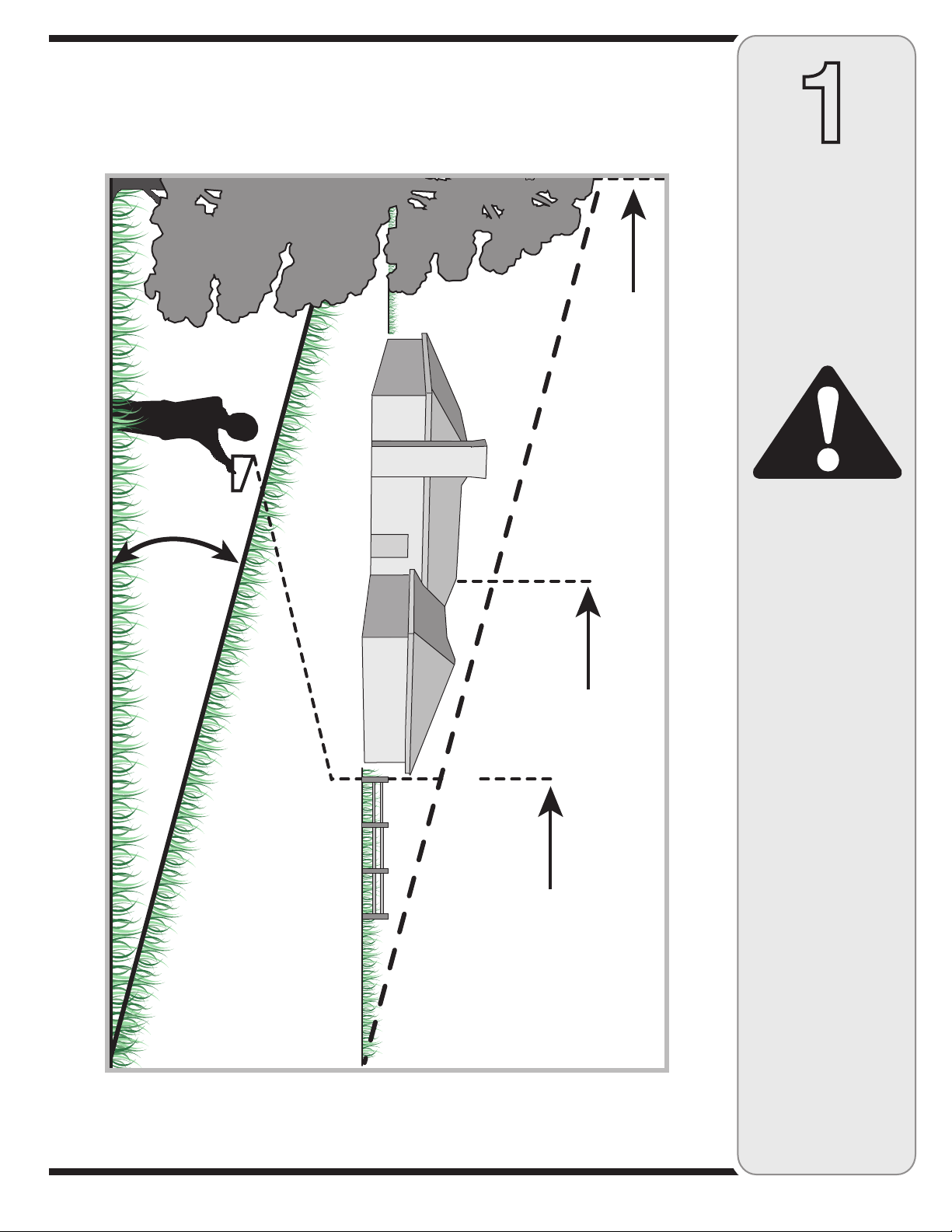
Use this page as a guide to determine slopes where you may not operate safely.
Do not operate your lawn mower on such slopes.
1
Slope
Gauge
WARNING
Do not mow on inclines
with a slope in excess
of 15 degrees (a rise
of approximately 2-1/2
feet every 10 feet).
Operate WALK-BEHIND
mowers across the
face of slopes, never
up and down slopes.
3
Page 4
WARNING: Engine Exhaust, some of its constituents, and certain vehicle components contain or emit chemicals known to State of California to cause cancer and
birth defects or other reproductive harm.
2
Safe
Operation
Practices
WARNING
This symbol points
out important safety
instructions which, if
not followed, could
endanger the personal
safety and/or property
of yourself and others.
Read and follow all
instructions in this
manual before attempting to operate
this machine. Failure
to comply with these
instructions may result
in personal injury. When
you see this symbol.
HEED ITS WARNING!
Your Responsibility
Restrict the use
of this power machine
to persons who read,
understand
and follow the warnings
and instructions
in this manual
and on the machine.
DANGER: This machine was built to be operated according to the rules for safe operation in this
manual. As with any type of power equipment, carelessness or error on the part of the operator
can result in serious injury. This machine is capable of amputating hands and feet and throwing
objects. Failure to observe the following safety instructions could result in serious injury or death.
Children
Tragic accidents can occur if operator is not alert to presence
of children. Children are often attracted to mower and mowing
activity. They do not understand the dangers. Never assume
that children will remain where you last saw them.
1. Keep children out of the mowing area and under watchful
care of a responsible adult other than the operator.
2. Be alert and turn mower off if a child enters the area.
3. Before and while moving backwards, look behind and down
for small children.
4. Use extreme care when approaching blind corners,
doorways, shrubs, trees, or other objects that may obscure
your vision of a child who may run into the mower.
5. Keep children away from hot or running engines. They can
suffer burns from a hot muffler.
6. Never allow children under 14 years old to operate a power
mower. Children 14 years old and over should read and
understand operation instructions and safety rules in this
manual and should be trained and supervised by a parent.
General Operation
1. Read this operator’s manual carefully in its entirety before
attempting to assemble this machine. Read, understand,
and follow all instructions on the machine and in the
manual(s) before operation. Be completely familiar with
the controls and the proper use of this machine before
operating it. Keep this manual in a safe place for future
and regular reference and for ordering replacement parts.
2. This machine is a precision piece of power equipment,
not a plaything. Therefore, exercise extreme caution at all
times. Your unit has been designed to perform one job: to
mow grass. Do not use it for any other purpose.
3. Never allow children under 14 years old to operate this
machine. Children 14 years old and over should read and
understand the instructions in this manual and should
be trained and supervised by a parent. Only responsible
individuals who are familiar with these rules of safe
operation should be allowed to use this machine.
4. Thoroughly inspect the area where the equipment is to
be used. Remove all stones, sticks, wire, bones, toys
and other foreign objects, which could be tripped over or
picked up and thrown by the blade. Thrown objects can
cause serious personal injury. Plan your mowing pattern
to avoid discharge of material toward roads, sidewalks,
bystanders and the like. Also, avoid discharging material
against a wall or obstruction, which may cause discharged
material to ricochet back toward the operator.
5. To help avoid blade contact or a thrown object injury,
stay in operator zone behind handles and keep children,
bystanders, helpers and pets at least 75 feet from mower
while it is in operation. Stop machine if anyone enters
area.
6. Always wear safety glasses or safety goggles during opera
tion and while performing an adjustment or repair to protect
your eyes. Thrown objects which ricochet can cause serious
injury to the eyes.
7. Wear sturdy, rough-soled work shoes and close-fitting
slacks and shirts. Shir ts and pants that cover the arms and
legs and steel-toed shoes are recommended. Never operate
this machine in bare feet, sandals, slippery or light-weight
(e.g. canvas) shoes.
8. Do not put hands or feet near rotating parts or under cutting
deck. Contact with blade can amputate hands and feet.
9. A missing or damaged discharge cover can cause blade
contact or thrown object injuries.
10. Many injuries occur as a result of the mower being pulled
over the foot during a fall caused by slipping or tripping.
Do not hold on to the mower if you are falling; release the
handle immediately.
11. Never pull the mower back toward you while you are
walking. If you must back the mower away from a wall or
obstruction first look down and behind to avoid tripping and
then follow these steps:
a. Step back from mower to fully extend your arms.
b. Be sure you are well balanced with sure footing.
c. Pull the mower back slowly, no more than half way
toward you.
d. Repeat these steps as needed.
12. Do not operate the mower while under the influence of
alcohol or drugs.
13. Do not engage the self-propelled mechanism on units so
equipped while starting engine.
14. The blade control handle is a safety device. Never attempt
to bypass its operation. Doing so makes the safety device
inoperative and may result in personal injury through
contact with the rotating blade. The blade control handle
must operate easily in both directions and automatically
return to the disengaged position when released.
15. Never operate the mower in wet grass. Always be sure of
your footing. A slip and fall can cause serious personal
injury. If you feel you are losing your footing, release the
blade control handle immediately and the blade will stop
rotating within three seconds.
16. Mow only in daylight or good artificial light. Walk, never run.
17. Stop the blade when crossing gravel drives, walks or roads.
18. If the equipment should start to vibrate abnormally, stop the
engine and check immediately for the cause. Vibration is
generally a warning of trouble.
-
4
Page 5

19. Shut the engine off and wait until the blade comes to a
complete stop before removing the grass catcher or unclog-
ging the chute.
The cutting blade continues to rotate for a few seconds after
the engine is shut off. Never place any part of the body in
the blade area until you are sure the blade has stopped
rotating.
20. Never operate mower without proper trail shield, discharge
cover, grass catcher, blade control handle or other safety
protective devices in place and working. Never operate
mower with damaged safety devices. Failure to do so can
result in personal injury.
21. Muffler and engine become hot and can cause a burn. Do
not touch.
22. Only use parts and accessories made for this machine by
manufacturer. Failure to do so can result in personal injur y.
23. If situations occur which are not covered in this manual,
use care and good judgment. Contact your dealer for
assistance.
Slope Operation
Slopes are a major factor related to slip and fall accidents, which
can result in severe injury. Operation on slopes requires extra
caution. If you feel uneasy on a slope, do not mow it. For your
safety, use the slope gauge included as par t of this manual to
measure slopes before operating this unit on a sloped or hilly
area. If the slope is greater than 15 degrees, do not mow it.
Do:
1. Mow across the face of slopes; never up and down. Exercise
extreme caution when changing direction on slopes.
2. Watch for holes, ruts, rocks, hidden objects, or bumps
which can cause you to slip or trip. Tall grass can hide
obstacles.
3. Always be sure of your footing. A slip and fall can cause
serious personal injury. If you feel you are losing your
balance, release the blade control handle immediately, and
the blade will stop rotating within 3 seconds.
Do Not:
1. Do not mow near drop-offs, ditches or embankments, you
could lose your footing or balance.
2. Do not mow slopes greater than 15 degrees as shown on
the slope gauge.
3. Do not mow on wet grass. Unstable footing could cause
slipping.
Service
Safe Handling Of Gasoline:
1. To avoid personal injury or property damage use extreme
care in handling gasoline. Gasoline is extremely flammable
and the vapors are explosive. Serious personal injury can
occur when gasoline is spilled on yourself or your clothes,
which can ignite. Wash your skin and change clothes
immediately.
2. Use only an approved gasoline container.
3. Never fill containers inside a vehicle or on a truck or trailer
bed with a plastic liner. Always place containers on the
ground away from your vehicle before filling.
4. Remove gas-powered equipment from the truck or trailer
and refuel it on the ground. If this is not possible, then refuel
such equipment on a trailer with a portable container, rather
than from a gasoline dispenser nozzle.
5. Keep the nozzle in contact with the rim of the fuel tank or
container opening at all times until fueling is complete. Do
not use a nozzle lock-open device.
6. Extinguish all cigarettes, cigars, pipes and other sources
of ignition.
7. Never fuel machine indoor because flammable vapors will
accumulate in the area.
8. Never remove gas cap or add fuel while engine is hot or
running. Allow engine to cool at least two minutes before
refueling.
9. Never over fill fuel tank. Fill tank to no more than ½ inch
below bottom of filler neck to provide for fuel expansion.
10. Replace gasoline cap and tighten securely.
11. If gasoline is spilled, wipe it of f the engine and equipment.
Move unit to another area. Wait 5 minutes before starting
engine.
12. Never store the machine or fuel container near an open
flame, spark or pilot light as on a water heater, space
heater, furnace, clothes dryer or other gas appliances.
13. To reduce fire hazard, keep mower free of grass, leaves,
or other debris build-up. Clean up oil or fuel spillage and
remove any fuel soaked debris.
14. Allow a mower to cool at least 5 minutes before storing.
General Service:
1. Never run an engine indoors or in a poorly ventilated area.
Engine exhaust contains carbon monoxide, an odorless
and deadly gas.
2. Before cleaning, repairing, or inspecting, make certain the
blade and all moving parts have stopped. Disconnect the
spark plug wire and ground against the engine to prevent
unintended starting.
3. Check the blade and engine mounting bolts at frequent
intervals for proper tightness. Also, visually inspect blade
for damage (e.g., bent, cracked, worn) Replace blade with
the original equipment manufacture’s (O.E.M.) blade only,
listed in this manual. “Use of parts which do not meet the
original equipment specifications may lead to improper
performance and compromise safety!”
4. Mower blades are sharp and can cut. Wrap the blade or
wear gloves, and use extra caution when servicing them.
5. Keep all nuts, bolts, and screws tight to be sure the equip
ment is in safe working condition.
6. Never tamper with safety devices. Check their proper
operation regularly.
7. After striking a foreign object, stop the engine, discon
nect the spark plug wire and ground against the engine.
Thoroughly inspect the mower for any damage. Repair the
damage before starting and operating the mower.
8. Never attempt to make a wheel or cutting height adjust
ment while the engine is running.
9. Grass catcher components, discharge cover, and trail
shield are subject to wear and damage which could
expose moving par ts or allow objects to be thrown. For
safety protection, frequently check components and re-
place immediately with original equipment manufacturer’s
(O.E.M.) par ts only, listed in this manual. “Use of parts
which do not meet the original equipment specifications
may lead to improper performance and compromise
safety!”
10. Do not change the engine governor setting or over-rev the
engine. The governor controls the maximum safe operating
speed of the engine.
11. Maintain or replace safety labels, as necessary.
12. Observe proper disposal laws and regulations. Improper
disposal of fluids and materials can harm the environment.
-
-
2
Safe
Operation
Practices
WARNING
This symbol points
out important safety
instructions, which if
not followed, could
endanger the personal
safety and/or property
of yourself and others.
Read and follow all
-
instructions in this manual before attempting to
operate this machine.
Failure to comply with
these instructions may
result in personal injury.
When you see this
symbol.
HEED IT’S WARNING!
Your Responsibility
Restrict the use
of this power machine
to persons who read,
understand
and follow the warnings
and instructions
in this manual
and on the machine.
5
Page 6
3
Assembly
All references to left,
right, front, and rear of the
machine are determined
by standing behind the
handlebars and facing the
direction of forward travel.
This operator’s manual
may cover various models.
The units illustrated may
vary slightly from your
unit.
Please carefully follow these assembly steps to
properly prepare your machine for use. We recommend that you read this section in its entirety before
beginning assembly.
WARNING: Disconnect the spark plug wire
and ground it against the engine to prevent
unintended starting.
Unpacking the Mower
Cut straps, if present, securing unit to pallet. Leave
1.
unit on pallet during assembly. Remove any protective packaging and tie straps if present.
Remove any loose parts, including the bag holding
2.
the Operator’s Manual, oil drain hose, water hose
coupler, and Engine Manual
Use the deck height lever (refer to Operation sec-
3.
tion) to raise the cutting deck to its highest position.
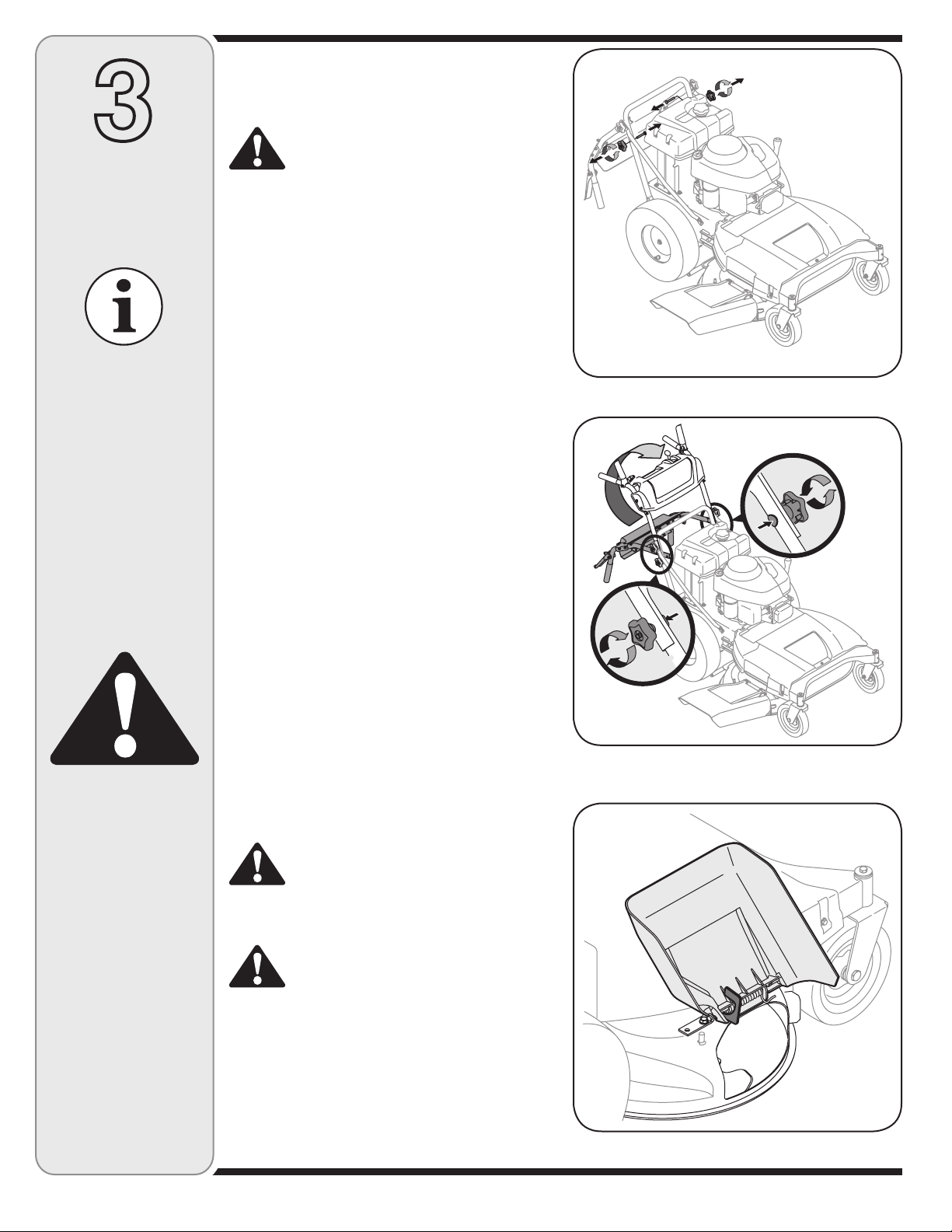
Handle Setup
Remove lower star knobs and carriage screws from
1.
lower handle, Figure 3-1.
Pivot upper handle into operating position. Be careful
2.
not to crimp cables, Figure 3-2.
Install carriage screws and knobs removed earlier.
3.
Tighten the upper and lower star knobs and carriage
4.
screws to secure the upper handle to the lower
handle, Figure 3-2.
After assembling the handle, to safely remove unit
5.
from pallet, first remove screws to free the mower
from the crate.
Figure 3-1: Remove lower star knobs and carriage screws.
WARNING
WARNING: The mowing
deck is capable of throwing objects. Failure to
operate the mower without
the discharge chute in the
proper operating position
could result in serious
personal injury and /or
property damage.
WARNING: The chute
holder must be removed
and discarded before
operating the mower.
Removing the Chute Holder
Locate the chute holder which secures the discharge
1.
chute in a vertical position, Figure 3-3.
Pull chute back towards engine. While holding the
2.
chute with one hand, remove the chute holder with
your other hand.
Carefully lower the chute against the deck and
3.
discard the chute holder.
WARNING: The chute holder, used for
packaging purposes only, must be removed and discarded before operating the
mower.
WARNING: The mowing deck is capable
of throwing objects. Failure to operate the
mower without the discharge chute in the
proper operating position could result in
serious personal injury and /or property
damage.
Figure 3-2: Pivot upper handle into position and secure with
knobs and screws.
Figure 3-3: Remove the chute holder.
6
Page 7
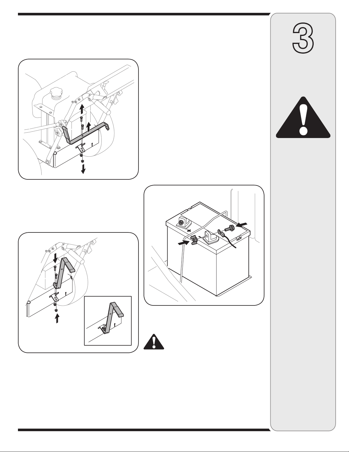
Shift Lever Setup
Remove the 5/16-18 screw and the lock nut that hold
1.
the shift lever to the shift lever plate, Figure 3-4.
Remove the remaining screw and nut from the lower
2.
shift lever plate, Figure 3-4.
Figure 3-4: Remove shift lever and hardware from plate.
Position the upper shift lever into a vertical position
3.
aligning the holes in the lever to the holes in the shift
plate, Figure 3-5.
Secure the lever to the plate using the two screws
4.
and two nuts removed earlier, Figure 3-5.
Attaching the Battery Cables
NOTE: Some models may be shipped with the battery
cables already connected.
NOTE: The positive battery terminal is marked Pos.
(+). The negative battery terminal is marked Neg. (–) .
NOTE: If the battery is put into service after the date
shown on top/side of battery, charge the battery as
instructed in the Maintenance section of this manual
prior to operating the mower.
The positive cable (heavy red wire) is secured to the
positive battery terminal (+) with a bolt and hex nut at
the factory. Make certain that the rubber boot covers the
terminal to help protect it from corrosion.
Remove the wing nut and bolt from the negative
1.
cable, Figure 3-6.
2.
Remove the plastic terminal cover, if present, from
the negative battery terminal and attach the negative
cable (heavy black wire) to the negative battery
terminal (–) with the nut and bolt.
3
Assembly
WARNING
WARNING: To prevent
personal injury or
property damage, do not
attempt to start the engine
until all assembly steps
are complete and you
have read the safety and
operating sections in this
manual.
WARNING: The mowing
deck is capable of throwing objects. Failure to
operate the mower without the discharge cover
in the proper operating
position could result in
serious personal injury
and/or property damage.
Figure 3-5: Attach the shift lever.
Figure 3-6: Connect negative cable to negative terminal.
Rear Tire Pressure
WARNING: Never exceed the maximum
inflation pressure shown on the sidewall
of tire.
The recommended operating rear tire pressure is
approximately 20 psi for the rear tires. Check the tire
pressure periodically and maintain equal pressure in both
rear tires at all times.
IMPORTANT: Refer to the tire sidewall for exact tire
manufacturer’s recommended or maximum psi. Do
not overinflate. Uneven tire pressure could cause the
cutting deck to mow unevenly.
7
WARNING: Never exceed
the maximum inflation
pressure shown on the
sidewall of tire.
Page 8
4
Operating
the Lawn
Mower
WARNING
Deck
Height
Lever
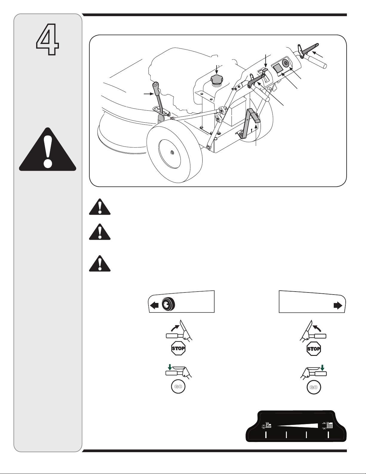
Know Your Lawn Mower
Throttle/Choke
Control Lever
Gas Cap
Gear Shift Lever
Blade
Control
Ignition Switch
Systems Indicator
Monitor
Drive Control
WARNING: Always remove
the ignition key when leaving mower unattended or
when performing any type
of maintenance on the
machine.
WARNING: If you strike
a foreign object, stop the
engine, disconnect the
spark plug wire (s) and
ground against the engine.
Thoroughly inspect the
machine for any damage.
Repair the damage before
restarting and operating.
WARNING: Read, understand, and follow all
instructions and warnings
posted on the machine
and in this manual before
operating.
WARNING: Never move
the key into the Start position while the engine is
running.
Figure 4-1
WARNING: Be familiar with all the controls and their proper operation; know how to stop the
machine and disengage them quickly.
WARNING: The operation of any lawn mower can result in foreign objects being thrown into the
eyes, which can damage your eyes severely. Always wear safety glasses while operating the
mower, or while performing any adjustments or repairs on it.
WARNING: Be sure no one other than the operator is standing near the lawn mower while starting
engine or operating mower. Never run engine indoors or in enclosed, poorly ventilated areas.
Engine exhaust contains carbon monoxide, an odorless and deadly gas. Keep hands, feet, hair
and loose clothing away from any moving parts on engine and lawn mower.
Drive Control
The drive control is used
to engage and disengage
drive to the wheels. To
engage this control,
squeeze the drive control
against the handlebar
grip. To stop the drive,
release the drive control.
IMPORTANT: Always
release the drive
control before changing
speeds.
DRIVE
CONTROL
GO
Blade Control
The blade control is used
to engage the mower
deck. To engage this
control, press and hold
the lever against the
handlebar grip. To stop
the blades, release the
blade control. Always
disengage the blade
control before starting
the engine. This helps to
ensure that the blades
will not start turning
when the engine starts.
BLADE
CONTROL
GO
Deck Height Lever
Use this lever to adjust the cutting height. To use, move the lever to the
left, then place the lever in the notch best suited for your application.
8
HEIGHT ADJUSTER
HL
Page 9
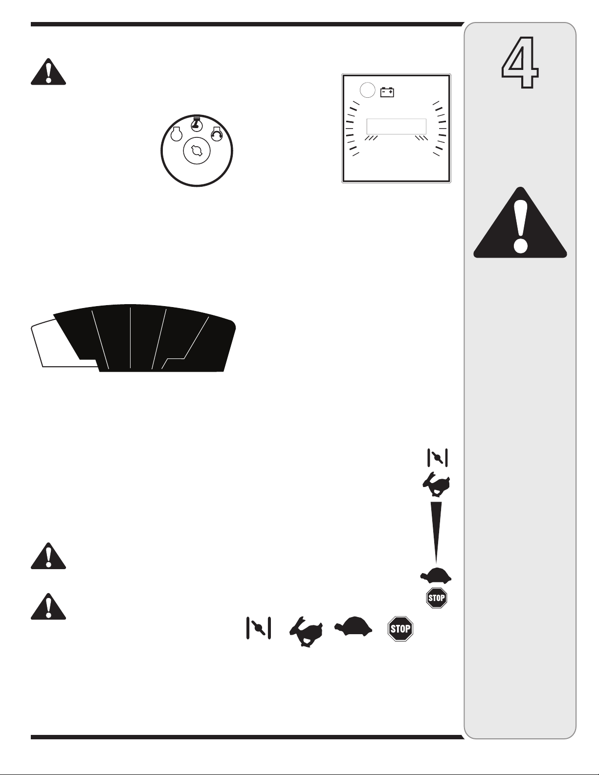
Ignition Switch
WARNING: Never move the key into the
Start position while the engine is running; doing so may cause damage to the
engine’s starter.
Off
Run
Start
The three-position switch is used
to start and stop the engine on
electric start models. Insert the
key into the ignition switch and
turn clockwise to the START
position. Release key into the
RUN position once the engine
has started. Turn the key to OFF
to stop the engine. Always remove the ignition key when
leaving mower unattended or when performing any type
of maintenance on the machine.
Gear Shift Lever
Use this lever to select any of four forward ground
speeds, neutral, or reverse.
R N 1 2 3 4
Forward
Four forward speeds are available. Position one (1) is the
slowest and position four (4) is the fastest.
Reverse
To select reverse, put the lever in the Reverse (R)
position.
Neutral
Place the lever in neutral (N) before starting the mower,
and when the mower is not in use. In addition, the mower
can be manually pushed or pulled by placing the gear
shift lever into N (neutral) position and pressing the drive
control against the handlebar grip.
WARNING: To avoid damaging the
transmission, do not shift gears when
the mower is moving – release the drive
control before shifting gears.
WARNING: Look behind the mower
before and during reverse operation. Stop
the mower blades before operating in
reverse.
Systems Indicator Monitor
LCD Display
The systems indicator
monitor records and
displays, on the LCD,
hours of mower operation
whenever the ignition
key is rotated out of the
STOP position. The
Indicator Monitor will also
remind the operator of
maintenance intervals
for changing the engine oil. The LCD will alternately flash
the recorded hours, “CHG” and “OIL” for five minutes,
after every 50 hours of recorded operation elapse. The
maintenance interval lasts for two hours (from 50-52,
100-102, 150-152, etc.). The LCD will also flash as
described above for five minutes every time the engine
has been started during this maintenance interval. Before
the interval expires, change the engine oil as instructed
in this Operator’s Manual.
BA
TTE
RY
HOURS 1/10
Battery Light
It is normal for the battery light to illuminate while the
engine is cranking during start-up, but if it illuminates
during operation, while the engine is running, the
battery is in need of a charge or the engine’s charging
system is not generating sufficient amperage. Refer to
the maintenance section in this manual for the proper
battery charging procedure or have the charging system
checked by a service dealer.
Throttle/Choke Control Lever
IMPORTANT: When operating the mower with
the cutting deck engaged, be certain that the
throttle/choke control lever is in the fast position.
This lever is used to adjust engine speeds, to
apply the engine choke, and to stop the engine.
Always run engine at fast speed setting for best
mower performance.
Choke: Use when starting a cold engine
Fast: Use during mower operation.
Slow: Use when idling engine.
Stop: Stops the engine.
4
Operating
the Lawn
Mower
WARNING
WARNING: The operation
of any lawn mower can
result in foreign objects
being thrown into the
eyes, which can damage
your eyes severely. Always wear safety glasses
while operating or servicing the mower.
WARNING: Be sure no
one other than the operator is standing near the
lawn mower while starting
engine or operating
mower. Never run engine
indoors or in enclosed,
poorly ventilated areas.
Engine exhaust contains
carbon monoxide, an
odorless and deadly gas.
Keep hands, feet, hair
and loose clothing away
from any moving parts on
engine and lawn mower.
Choke Fast Slow/Idle Engine Off
9
Page 10

4
Operating
the Lawn
Mower
Engine Controls
Refer to Figure 4-2 for locations of the engine controls.
Refer to the engine manual for more detailed information.
Recoil Starter
The recoil starter is used to pull-start the engine.
Oil Drain Valve
Use the oil drain valve to drain oil from the engine. Refer
to the Maintenance section for instructions.
Air Cleaner Handle
The air cleaner handle is used to gain access to the air
cleaner. The air cleaner cartridge can be removed and
cleaned or replaced. Refer to the Maintenance section
for instructions.
Recoil Starter
Oil Cap/
Dipstick
Oil
Drain
Valve
Electric Starter
Figure 4-2: Engine components
Muffler and
Muffler Guard
Air Cleaner
Handle
Spark
Plug Wire
Spark Plug
WARNING
WARNING: If you strike
a foreign object, stop the
engine. Remove wire from
the spark plug, thoroughly inspect mower for
any damage, and repair
damage before restarting
and operating. Extensive vibration of mower
during operation is an
indication of damage. The
unit should be promptly
inspected and repaired.
Spark Plug/Spark Plug Wire
Refer to the Maintenance section for instructions on
spark plug replacement.
Oil Cap/ Dipstick
Refer the Maintenance section for instructions on
changing the oil.
Refer to the engine manual for help with engine
controls and maintenance.
10
Page 11

WARNING: The operation of any lawn mower can result in foreign objects being thrown into the
eyes, which can damage your eyes severely. Always wear safety glasses while operating the
mower, or while performing any adjustments or repairs on it.
WARNING: Be sure no one other than the operator is standing near the lawn mower while starting
engine or operating mower. Never run engine indoors or in enclosed, poorly ventilated areas.
Engine exhaust contains carbon monoxide, an odorless and deadly gas. Keep hands, feet, hair,
and loose clothing away from any moving parts on engine and lawn mower.
WARNING: Use extreme care when handling gasoline. Gasoline is extremely flammable and the
vapors are explosive. Never fuel machine indoors or while the engine is hot or running. Extinguish cigarettes, cigars, pipes, and other sources of ignition.
Gas and Oil Fill-up
Gas Fill
The mower is shipped without gas in the fuel tank.
WARNING: Alcohol blended fuels (called
gasohol or using ethanol or methanol)
can attract moisture which leads to
separation and formation of acids during
storage. Acidic gas can damage the fuel
system of an engine while in storage.
WARNING: To avoid engine problems,
the fuel system should be emptied before
storage for 30 days or longer. Drain the
gas tank, start the engine and let it run
until the fuel lines and carburetor are
empty. Use fresh fuel next season. See
STORAGE Instructions for additional
information.
Oil Fill
IMPORTANT: The mower is shipped with motor oil
in the engine; however, you must check the oil level
before operating. For future oil fills, use the grade of
engine oil specified in the Maintenance section.
Remove the oil fill cap/dipstick from the oil fill tube.
1.
Check that the level of oil is up to the FULL mark on
2.
the dipstick. If needed, pour oil slowly into the oil fill
tube until a FULL oil level is achieved.
Replace the oil fill cap/dipstick.
3.
4
Operating
the Lawn
Mower
WARNING
WARNING: Keep hands
and feet clear of mower
blades or other rotating
parts.
WARNING: Look behind
you to be sure there are no
obstacles before starting
the unit.
WARNING: Never use engine or carburetor cleaner products in the fuel tank or
permanent damage may occur.
Never fill the fuel tank completely. Fill the tank to
•
no more than 1/2-inch below bottom of filler neck to
provide space for fuel expansion.
Always use clean, fresh, unleaded grade automotive
•
gasoline. Fill the fuel tank outdoors and use a funnel
or spout to prevent spilling. Make sure that the
container from which you pour the gasoline is clean
and free from rust or other foreign particles. Make
sure to wipe off any spilled fuel before starting the
engine.
At the end of the job, empty the fuel tank if the
•
mower is not going to be used for 30 days or longer.
Store gasoline in a clean container and keep the
cap in place on the container. See STORAGE
instructions for additional information.
11
Page 12

4
Operating
the Lawn
Mower
WARNING
WARNING: If you strike
a foreign object, stop the
engine. Remove wire from
the spark plug, thoroughly inspect mower for
any damage, and repair
damage before restarting
and operating. Extensive vibration of mower
during operation is an
indication of damage. The
unit should be promptly
inspected and repaired.
WARNING: Keep hands
and feet clear of mower
blades or other rotating
parts.
WARNING: Look behind
you to be sure there are no
obstacles before starting
the unit.
Starting the Mower
Release all controls on the mower to prevent wheels
1.
or blades from rotating.
Move gear shift lever to neutral (N) position.
2.
Move the throttle /choke control lever fully upward to
3.
the choke setting to start a cold engine or to the fast
(rabbit) setting to start a warm engine.
To start engine using recoil starter:
4.
Stand on left side (as viewed from behind
a.
handlebars) of machine. Be sure your feet are
safely away from the underside of the mower
deck and all mower controls are released.
Grasp starter rope handle and pull slowly until
b.
rope pulls slightly harder. Let rope rewind
slowly. Then pull rope with a rapid, full arm
stroke. Let rope return slowly. If engine fails to
start after three pulls, repeat instructions (try
setting throttle at fast setting).
When engine starts, operate in fast throttle
c.
setting (move throttle/choke control lever from
the choke setting to the fast setting).
To start engine using electric starter:
4.
Stand behind the handlebars and release all
a.
mower controls.
Turn ignition key fully clockwise to the START
b.
position. To avoid damage to starter motor, do
not crank engine for longer than five seconds
at a time. Also, allow 15 seconds between each
start attempt. If engine fails to start after three
attempts, repeat instructions with Step 3 (try
setting throttle/choke lever at fast setting).
When engine starts, release key and it will
c.
return to the run (middle) position.
Operate engine at fast throttle setting (move
d.
throttle/choke control lever from choke setting
to fast setting).
NOTE: If the electric start system is not functioning,
the engine can be started with the recoil starter. To
do so, first put the ignition key in the run (middle)
position. Leave the key in the run position during
engine operation.
WARNING: Look behind the mower
before and during reverse operation.
Stop the mower blades before operating
in reverse.
Stopping the Mower
1.
Release blade and drive control to stop wheels and
deck blades.
2.
Move throttle/choke control lever down to slow
(turtle) position. Whenever possible, gradually
reduce engine speed before stopping engine.
3.
Move throttle/choke control lever all the way down
to stop position or turn the ignition key fully counterclockwise to OFF position.
On electric start models, remove the ignition key
4.
before leaving the mower unattended.
Disconnect spark plug wire from spark plug and
5.
ground against the engine.
WARNING: Wait for the blade to stop
completely before performing any type of
maintenance on the mower.
Using the Lawn Mower
Refer to “Know your Mower” section for mower control
details.
Be sure lawn is clear of stones, sticks, wire, or other
objects which could damage lawn mower or engine.
Such objects could be accidently thrown by the mower
in any direction and cause serious personal injury to
the operator and others. For best results, do not cut wet
grass and never cut off more than one-third of the total
length of the grass.
IMPORTANT: Be aware that when engaging the drive
control lever with the gear shift lever in 3rd or 4th gear,
the power and torque generated may cause the unit to
lurch forward. To avoid this, slowly squeeze the drive
control lever against the upper handle.
Once the engine is running, squeeze the drive
1.
control against the upper handle to propel the unit.
To activate the cutting blades, squeeze the blade
control against the upper handle.
To change gears, release the drive control lever and
2.
move the gear lever to the desired setting. When
first practicing with the mower, put the lever in No.
1 position. Select forward speeds according to
mowing conditions and terrain. Use slower speeds
on rough terrain or when grass is heavy or thick. The
forward speed can be increased on smooth terrain
or if the grass cover is light. Allow the wheels to stop
completely before shifting from one forward speed
into another.
To stop the blades, release the blade control. To
3.
stop the drive control to the wheels, release the drive
control.
Moving the Mower without
Engine Power
The mower can be manually pushed or pulled by placing
the gear shift lever into N (neutral) position and pressing
the drive control against the handlebar grip.
12
Page 13

Mulching or Side-Discharge Mowing
You can use the mower either as a mulching mower or
as a side-discharge mower. To use the mulching feature,
insert the mulch plug as described below. Remove the
mulch plug to side-discharge grass clippings. The
mulch plug is designed to keep the discharge chute
raised up while mowing. When the plug is removed, the
discharge chute will lower itself for side-discharge
mowing.
To install or remove mulch plug :
Stop the engine and wait for all parts to stop moving.
1.
Disconnect the spark plug wire from the spark plug.
2.
Remove the ignition key on electric start models.
3.
To install the mulch plug, insert the right-side tab (A)
4.
of the plug into the bracket on the deck, Figure 4-3.
Insert the mulch plug into the discharge opening
5.
(B), Figure 4-3.
After the mulch plug has been placed into the deck
6.
opening, push the plug towards the rear of the
mower (C) to fit the plug properly into the opening,
Figure 4-3.
To remove the plug, slide the cover to the right (front
7.
of mower) to disengage the slot from the mower
deck and then pry the left-side of the plug out and
off.
WARNING: Before installing or removing
mulch plug, stop engine, wait for parts to
stop moving, and disconnect spark plug
wire. Remove ignition key on electric start
models.
WARNING: Keep hands and feet away
from the discharge opening of the cutting
deck.
C
B
A
4
Operating
the Lawn
Mower
WARNING
WARNING: Before installing or removing mulch
plug, stop engine, wait for
parts to stop moving, disconnect spark plug wire,
and remove ignition key.
Figure 4-3: Installation of the mulch plug.
WARNING: Keep hands
and feet clear of mower
blades or other rotating
parts.
WARNING: Look behind
you to be sure there are no
obstacles before starting
the unit.
13
Page 14

5
Maintaining
the Lawn
Mower
WARNING
WARNING: Always stop
engine, disconnect spark
plug, and remove ignition
key before performing any
type of maintenance on
the mower. Failure to follow this instruction could
result in personal injury
and/or property damage.
WARNING: Check oil level
in engine before every
use.
WARNING: If filters or
covers are not installed
correctly, serious injury
or death could result from
backfire. Do not attempt to
start the engine with them
removed.
General Recommendations
Always observe safety rules when performing any type of maintenance on the mower.
•
The warranty on this lawn mower does not cover items that have been subjected to operator abuse or negli-
•
gence. To receive full value from warranty, operator must maintain the lawn mower as instructed here.
Changing of engine-governed speed will void engine warranty.
•
All adjustments should be checked at least once each season.
•
Periodically check all fasteners and make sure they are tight.
•
WARNING: Before performing any type of maintenance or service on the mower, stop engine,
disconnect spark plug, and ground against engine. Remove ignition key from the keyswitch.
Engine Maintenance
WARNING: Always stop engine, disconnect spark plug, and remove ignition key
before performing any type of maintenance on the mower.
Refer to engine manual for more detailed maintenance
and service instructions.
Spark Plug
Clean spark plug and reset the electrode gap to 0.030”
at least once a season; replace every 100 hours of
operation. Spark plug should be cleaned by scraping or
wire brushing and washing with a commercial solvent.
Clean area around the spark plug base.
1.
Remove and inspect the spark plug. Check gap to
2.
make sure it is set at .030”. See Figure 9.
Replace the spark plug if electrodes are pitted,
3.
burned, or the porcelain is cracked.
Electrode
.030 inch (.76 mm) gap
Porcelain
Servicing the Air Cleaner
WARNING: If filters or covers are not
installed correctly serious injury or death
could result from backfire. Do not attempt
to start the engine with them removed.
CAUTION: Do not use pressurized air or
solvents to clean the air cleaner cartridge.
1.
Pull up on air cleaner handle, Figure 5-2, and pull
back towards the engine.
2.
Remove the air cleaner cover, Figure 5-2.
3.
Carefully remove air cleaner cartridge and precleaner (if equipped) from the blower housing.
4.
Clean the base of the air cleaner cartridge carefully
to prevent debris from entering the engine.
5.
Place the pre-cleaner, if equipped, and cartridge
back into the blower housing. The cartridge must be
placed securely into position.
6.
Align tabs on cover with slots in blower housing and
replace the cover.
Air Cleaner Cover
Air Cleaner Handle
Air Cleaner Cartridge
Do not use a pressure
washer or garden hose
to clean your unit. These
may cause damage to
electric components,
spindles, pulleys, bearings, or the engine. The
use of water will result
in shortened life and
reduced serviceability.
Figure 5-1: Spark plug
Figure 5-2: Use the air cleaner handle to access the air cleaner
cartridge.
14
Page 15

A
B
Oil Drain Valve
Figure 5-3: Pivot the right brace support tube forward to gain
access to the oil valve.
Oil Fill Cap/
Dipstick
Protective
Drain Cap
Oil Drain Valve
Oil Drain Hose
Figure 5-4: Use the drain hose to drain oil from engine.
Colder
5W30
Oil Viscosity Chart
SAE 30
Warmer
Changing the Engine Oil
CAUTION: Check oil level in engine
before every use.
To gain access to the oil drain valve on the engine,
1.
the right handle brace tube should be pivoted
forward.
Remove the upper star knob and carriage
a.
screw on the right side of the handle,
Figure 5-3.
Pivot the brace tube forward towards the front
b.
of the mower to allow room to connect the oil
drain hose to the oil drain valve, Figure 5-3.
Pop off the protective cap on the end of the oil drain
2.
valve to expose the drain port, Figure 5-4.
Remove the oil fill cap/dipstick from the oil fill tube,
3.
Figure 5-4.
Push the oil drain hose (packed with this manual)
4.
onto the oil drain port. Route the opposite end of the
hose into an appropriate oil collection container with
a capacity great enough to collect the used oil.
Release the valve by pressing the two tabs inward
5.
while pulling the valve out. The oil will begin to drain
out of the engine.
After the oil has finished draining, press the two
6.
tabs inward and push the oil drain valve back in to
lock the valve closed. Remove the hose, and re-cap
the end of the oil drain valve to keep debris from
entering the drain port.
Refill the engine with new motor oil until the oil
7.
level on the dipstick reads FULL. Replace the oil fill
cap/dipstick.
Pivot the right handle brace tube back into position.
8.
Align the middle hole in the brace tube with the
hole in the handle. Secure with the star knob and
carriage screw removed earlier.
Only use high quality detergent oil rated with API service
classification SF or SG. Select the oil’s SAE viscosity
grade according to your expected operating temperature,
Figure 5-5. Although multi-viscosity oils (5W30, 10W30
etc.) improve starting in cold weather, these multi-viscosity oils will result in increased oil consumption when used
above 32°F. Check your engine oil level more frequently
to avoid possible engine damage from running low on oil.
5
Maintaining
the Lawn
Mower
WARNING
WARNING: Always stop
engine, disconnect spark
plug, and remove ignition
key before performing any
type of maintenance on the
mower. Failure to follow
this instruction could result
in personal injury and /or
property damage.
WARNING: Check oil level
in engine before every use.
Figure 5-5: Oil Viscosity Chart
15
Page 16

5
Mower Maintenance
WARNING: Before performing any type of maintenance/ service, disengage all controls and stop
the engine. Wait until all moving parts have come to a complete stop. To prevent unintended
starting, disconnect spark plug wire and ground it against the engine and remove ignition key.
Always wear safety glasses during operation or while performing any adjustments or repairs.
Maintaining
the Lawn
Mower
WARNING
WARNING: Before
performing any type of
maintenance on the machine, wait for all parts to
stop moving, disconnect
the spark plug wire, and
remove the ignition key
from the ignition switch.
Failure to follow this
instruction could result
in personal injury and /or
property damage.
Removing the Belt Cover
WARNING: Do not operate unit without
belt cover installed. Failure to follow this
instruction could result in personal injury
or property damage.
The belt cover must be removed to perform several
maintenance procedures. Follow the instructions below
to remove the belt cover.
Stop engine, wait for all parts to stop moving, and
1.
disconnect spark plug wire.
Remove the three screws and washers holding the
2.
cover to the frame, Figure 5-6.
Remove the belt cover.
3.
To reinstall the cover, place the cover in position and
4.
fasten using screws and washers removed earlier.
Figure 5-6: Remove screws and washers to remove belt cover.
Removing the Mower Deck
When servicing the underside of the mower deck for any
reason, the cutting deck should first be removed. Follow
the instructions below to remove the cutting deck:
Stop the engine, wait for all parts to stop moving,
1.
and disconnect spark plug wire.
Release all mower controls.
2.
Remove belt cover as instructed under “Removing
3.
the Belt Cover.”
Use the deck height lever to move the cutting deck
4.
to its highest position.
Place small wooden blocks under the deck.
5.
Use the deck height lever to lower the deck so that it
6.
rests upon the wooden blocks.
Looking at the cutting deck from the left side of the
7.
mower, located the hairpin clip that secures the
deck support rod on the rear left side of the deck,
Figure 5-7.
Remove the hairpin clip that secures the support
8.
rod, and carefully remove the deck support from the
deck lift arm, Figure 5-7.
Repeat steps 7 and 8 on the mower’s right side.
9.
When complete, all four hairpin clips should be
removed.
Push the cutting deck to the left to unhook the lift
10.
assembly from the deck.
Use the deck height lever to raise the cutting deck
11.
to its highest position.
Remove the wooden blocks from under the deck.
12.
Remove the drive belt as instructed under “Replac-
13.
ing the Drive Belt” instructions.
Slide the cutting deck towards the rear of the unit.
14.
Unhook the drive spring cable from the idler arm
15.
assembly, Figure 5-8.
Remove the cutting deck.
16.
To install the cutting deck, follow the above steps in
17.
reverse order to reattach deck and belt cover.
Figure 5-7: Remove hairpin clips. Figure 5-8: Unhook spring.
16
Page 17

Lubrication
Pivot Points & Linkage
Lubricate all the pivot points on the drive system and lift
linkage at least once a season, or 25 hours of operation,
with light oil.
5
Rear Wheels
The rear wheels should be removed from the axles once
a season. Lubricate the axles and the rims well with an
all-purpose grease before reinstalling them.
Front Wheel Bearings
Grease fittings are located on each caster wheel and
on the frame above each front caster wheel, Figure 5-9.
Lubricate these areas using a grease gun after every 50
hours of mower operation.
To lubricate a caster wheel bearing, rotate the wheel so
that the grease fitting is in alignment with the notch in
the bracket, Figure 5-9 − doing this will allow room to
connect the grease gun coupler onto the grease fitting.
You will not need to use the grease fitting on the opposite
side of the wheel.
Cleaning the Engine and Deck
Any fuel or oil spilled on the machine should be wiped off
promptly. Do NOT allow debris to accumulate around any
components on the mower. Do not use a pressure washer
to clean the mower. It may cause damage to electrical
components, spindles, pulleys, bearings, or the engine.
Deck Wash System™
Use the Deck Wash System™ to rinse grass clippings
from the deck’s underside and prevent the buildup of
corrosive chemicals.
Thread the hose coupler (packaged in a bag with
1.
the Operator’s Manual) onto the end of your garden
hose, Figure 5-10.
Attach the hose and coupler to the water port on the
2.
deck surface, Figure 5-10.
Turn the water on.
3.
Point the discharge chute away from any objects or
4.
persons.
Start the mower and engage the blades for a
5.
minimum of two minutes. Do not engage the drive
control.
When complete, disengage the blade control
6.
(release the blade control lever) and turn the engine
off.
Turn the water off and detach the hose coupler from
7.
the water port.
Grease
fitting on
frame
Align grease fitting with
notch in wheel bracket
Figure 5-9: Grease fittings for caster wheels.
Garden
Hose
Hose
Coupler
Water Port
Figure 5-10: Use the Deck Wash System™ to clean the underside of the cutting deck.
Replacing the Trailing Shield
If screws are located at each side of the trailing
1.
shield, remove the two screws. Bend (bow) the
trailing shield inward on each side to release tabs
from the holes in the mower frame, Figure 5-11.
Replace with new trailing shield by bending the
2.
shield to allow each tab to fit into hole in mower
frame. Replace the two screws (if present).
Maintaining
the Lawn
Mower
WARNING
WARNING: Always stop
engine, disconnect spark
plug, and remove ignition
key before performing
any type of maintenance
on the mower. Failure to
follow this instruction
could result in personal
injury and /or property
damage.
WARNING: Do not use a
pressure washer to clean
the mower. It may cause
damage to electrical
components, spindles,
pulleys, bearings, or the
engine.
WARNING: Do not operate the mower without the
trailing shield properly
installed.
Figure 5-11: The trailing shield
17
Page 18

5
Maintaining
the Lawn
Mower
WARNING
WARNING: Always stop
engine, disconnect spark
plug, and remove ignition
key before performing any
type of maintenance on
the mower. Failure to follow this instruction could
result in personal injury
and/or property damage.
WARNING: Never exceed
the maximum inflation
pressure shown on the
sidewall of the tire.
Rear Tire Pressure
WARNING: Never exceed the maximum
inflation pressure shown on the sidewall
of tire.
The recommended operating rear tire pressure is approximately 20 psi for the rear tires.
IMPORTANT: Refer to the tire sidewall for exact tire
manufacturer’s recommended or maximum psi. Do
not overinflate. Uneven tire pressure could cause the
cutting deck to mow unevenly.
Servicing the Cutting Blades
WARNING: Be sure to shut the engine
off and disconnect the spark plug wire
and ground against the engine to prevent
unintended starting before removing
the cutting blade(s) for sharpening or
replacement. Protect your hands by
using heavy gloves or a rag to grasp the
cutting blade.
WARNING: Periodically inspect the blade
spindles for cracks or damage, especially
if you strike a foreign object. Replace
immediately if damaged.
WARNING: Mower blades are sharp.
When working near blades, wear heavy
leather gloves or wrap blades in thick
rags to protect yourself from the sharp
edges
Blade Removal
Remove the deck from beneath the mower and gen-
1.
tly flip the deck over to expose its underside. Refer
to “Removing the Mower Deck” for instructions.
Place a block of wood between the deck housing
2.
and the cutting blade to act as a stabilizer,
Figure 5-12.
Remove the hex flange nut that secures the blade to
3.
the spindle assembly, Figure 5-12.
Flange Nut
Wood block
Figure 5-12: Use a block of wood to stabilize blade.
Figure 5-13: Grind cutting edges following angle.
Blade Sharpening
IMPORTANT: If any metal separation is present, replace
the blades with new ones.
To properly sharpen the cutting blades, remove
1.
equal amounts of metal from both ends of the
blades along the cutting edges, parallel to the
trailing edge, at a 25° to 30° angle, Figure 5-13.
It is important that each cutting blade edge be
•
ground equally to maintain proper blade balance. A
poorly balanced blade will cause excessive vibration
and may cause damage to the mower and result in
personal injury. The blade can be tested by balancing it on a round shaft screwdriver. Grind metal from
the heavy side until it balances evenly.
Blade Installation
When installing a blade, be sure to install the
1.
blade with the side of the blade with a part number
stamped in it facing the ground when the mower is in
the operating position.
Use a torque wrench to tighten the spindle flange nut
2.
to between 70-90 foot-pounds.
18
Page 19
Battery Maintenance
Battery
The battery is sealed and is maintenance-free. Acid levels
cannot be checked.
Always keep the battery cables and terminals clean
•
and free of corrosive build-up.
After cleaning the battery and terminals, apply a light
•
coat of petroleum jelly or grease to both terminals.
Always keep the rubber boot positioned over the
•
positive terminal to prevent shorting.
IMPORTANT: If removing the battery for any reason,
disconnect the NEGATIVE (Black) wire from it’s
terminal first, followed by the POSITIVE (Red) wire.
When re-installing the battery, always connect the
POSITIVE (Red) wire its terminal first, followed by the
NEGATIVE (Black) wire. Be certain that the wires are
connected to the correct terminals; reversing them
could change the polarity and result in damage to
your engine’s alternating system.
Charging
IMPORTANT: When charging the battery, use only a
charger designed for 12V lead-acid batteries. Read
your battery charger’s Owner’s Manual prior to
charging the battery. Always follow its instructions
and heed its warnings.
If the mower has not been put into use for an extended
period of time, charge the battery as follows:
Set the battery charger to deliver a maximum of 10
•
amperes. If the battery charger is automatic, charge
the battery until the charger indicates that charging
is complete.
NOTE: If the charger is not automatic, charge for no
fewer than eight hours.
WARNING: Batteries give off an explosive
gas while charging. Charge battery in a
well ventilated area and keep away from
an open flame or pilot light as on a water
heater, space heater, furnace, clothes
dryer or other gas appliances.
Jump Starting
WARNING: When removing or installing
the battery, follow these instructions to
prevent the screwdriver from shorting
against the frame.
IMPORTANT: Never jump the mower’s dead battery
with the battery of a running vehicle.
1.
Connect end of one jumper cable to the positive
terminal of the good battery, then the other end to
the positive terminal of the dead battery.
Connect the other jumper cable to the negative
2.
terminal of the good battery, then to the frame of the
unit with the dead battery.
WARNING: Failure to use this procedure
could cause sparking, and the gas in
either battery could explode.
Cleaning
Clean the battery by removing it from the mower and
washing with a baking soda and water solution. If necessary, scrape the battery terminals with a wire brush to
remove deposits. Coat terminals and exposed wiring with
grease or petroleum jelly to prevent corrosion.
Battery Failures
Some common causes for battery failure are:
incorrect initial activation
•
undercharging
•
overcharging
•
corroded connections
•
freezing
•
These failures are NOT covered by the mower warranty.
Fuse
One 20 AMP fuse is installed in the mower’s wiring harness to protect the electrical system from damage caused
by excessive amperage. If the electrical system does not
function, or the engine will not crank, first check to be
certain that the fuse has not blown. The fuse is located
near the battery.
WARNING: Always use a fuse with the
same amperage capacity for replacement.
5
Maintaining
the Lawn
Mower
WARNING
WARNING: Always stop
engine, disconnect spark
plug, and remove ignition
key before performing any
type of maintenance on
the mower. Failure to follow this instruction could
result in personal injury
and/or property damage.
WARNING: Always use
a fuse with the same
amperage capacity for
replacement.
WARNING: Batteries give
off an explosive gas while
charging. Charge battery
in a well ventilated area
and keep away from an
open flame or pilot light as
on a water heater, space
heater, furnace, clothes
dryer or other gas appliances.
19
Page 20

5
Maintaining
the Lawn
Mower
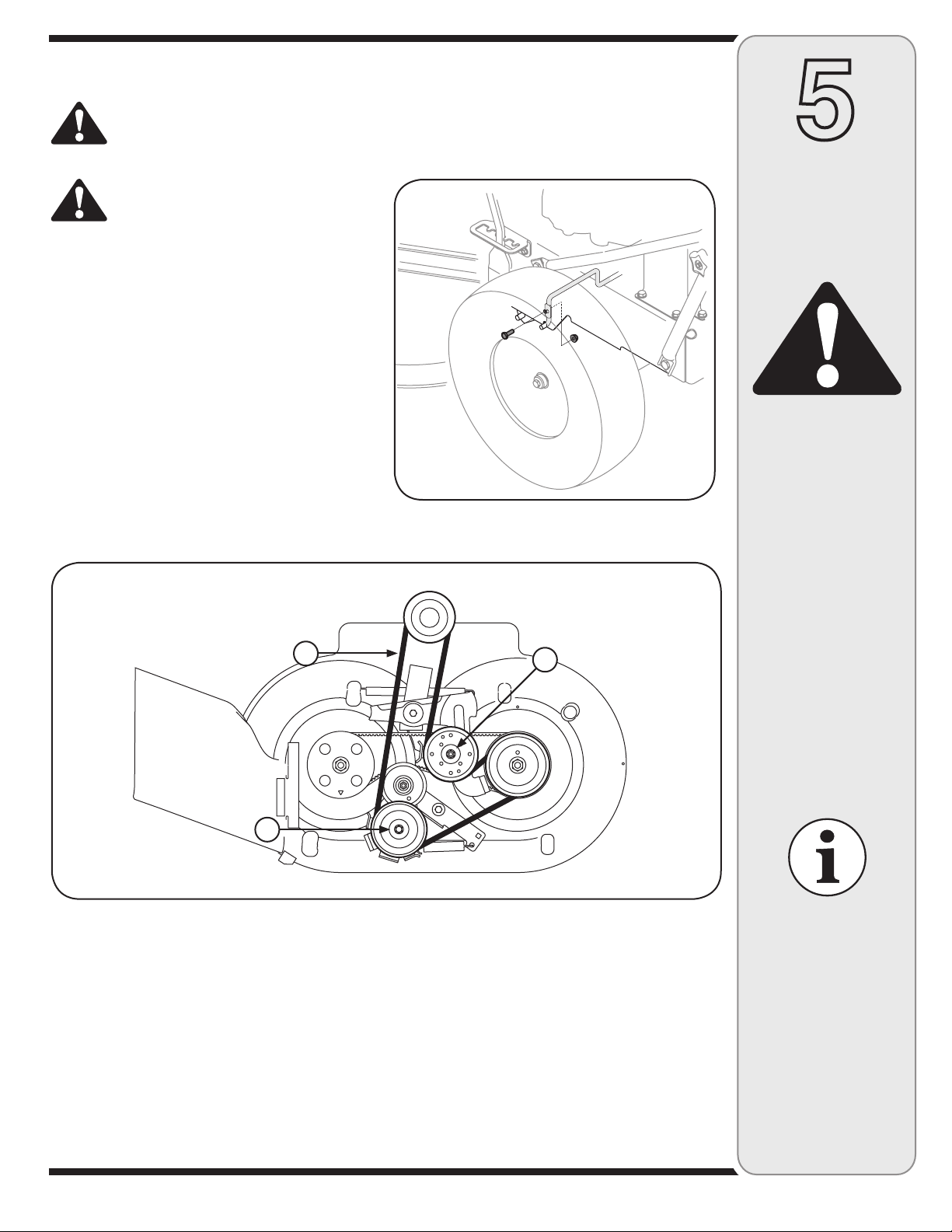
Replacing Belts
The mower uses three belts: 1) drive belt, 2) deck engagement belt, 3) blade timing belt. Before removing belt,
observe how the belt is routed around the pulleys and brackets to help when installing a replacement belt.
IMPORTANT: The belts on the mower are specially designed to engage and disengage safely. Substitute
(non-OEM) belts can be dangerous by not disengaging completely. For a proper working machine, use factory approved belts.
Replacing the Drive Belt
WARNING: Before performing any type of maintenance on the machine, wait for all parts to stop
moving, and disconnect the spark plug wire. Remove the ignition key from the ignition switch (if
equipped). Failure to follow this instruction could result in personal injury or property damage.
WARNING
WARNING: Always stop
engine, disconnect spark
plug, and remove ignition
key before performing any
type of maintenance on
the mower. Failure to follow this instruction could
result in personal injury
and/or property damage.
WARNING: Avoid the
possibility of a pinching
injury. Do not place your
fingers between belts and
pulleys.
Avoid the possibility of a pinching injury.
Do not place your fingers between belts
and pulleys.
Stop engine, wait for all parts to stop moving, and
1.
disconnect spark plug wire.
Release all mower controls.
2.
Remove belt cover as instructed earlier in this
3.
section.
Loosen belt keeper (A). The belt keeper is attached
4.
to the underside of the mower frame, Figure 5-14.
Loosen the idler pulley (B) by loosening bolt and nut,
5.
Figure 5-14.
Remove belt (C) from around pulleys, Figure 5-14.
6.
Route new belt around the pulleys making sure to
7.
tighten nuts, bolts, and belt keeper.
Replace the belt cover.
8.
A
C
B
IMPORTANT: The belts
on the mower are specially designed to engage
and disengage safely.
Substitute (non-OEM)
belts can be dangerous by not disengaging
completely. For a proper
working machine, use
factory approved belts.
Figure 5-14: Top view of the drive belt orientation.
20
Page 21
Replacing the Deck Engagement Belt
WARNING: Before performing any type of maintenance on the machine, wait for all parts to stop
moving, and disconnect the spark plug wire. Remove the ignition key from the ignition switch (if
equipped). Failure to follow this instruction could result in personal injury or property damage.
5
Avoid the possibility of a pinching injury.
Do not place your fingers between belts
and pulleys.
Stop engine, wait for all parts to stop moving, and
1.
disconnect spark plug wire.
Release all mower controls.
2.
Remove belt cover as instructed earlier in this
3.
section.
Loosen the bolt and nut holding the belt keeper rod
4.
to the frame, Figure 5-15.
Loosen the idler pulley (A) by loosening the nut and
5.
bolt, Figure 5-16.
Loosen the idler pulley (B) by loosening nut, Figure
6.
5-16.
Remove belt (C) from around pulleys, Figure 5-16.
7.
Route new belt around the pulleys making sure to
8.
tighten nuts, bolts, and belt keeper.
Replace the belt cover.
9.
Figure 5-15: Loosen the belt keeper rod.
Maintaining
the Lawn
Mower
WARNING
WARNING: Always stop
engine, disconnect spark
plug, and remove ignition
key before performing
any type of maintenance
on the mower. Failure to
follow this instruction
could result in personal
injury and /or property
damage.
C
B
Figure 5-16: Top view of deck engagement belt orientation.
A
WARNING: Avoid the
possibility of a pinching
injury. Do not place your
fingers between belts and
pulleys.
IMPORTANT: The belts
on the mower are specially designed to engage
and disengage safely.
Substitute (non-OEM)
belts can be dangerous by not disengaging
completely. For a proper
working machine, use
factory approved belts
21
Page 22

5
Maintaining
the Lawn
Mower
WARNING
WARNING: Always stop
engine, disconnect spark
plug, and remove ignition
key before performing
any type of maintenance
on the mower. Failure to
follow this instruction
could result in personal
injury and /or property
damage.
Replacing the Blade Timing Belt
WARNING: Before performing any type of maintenance on the machine, wait for all parts to stop
moving, and disconnect the spark plug wire. Remove the ignition key from the ignition switch (if
equipped). Failure to follow this instruction could result in personal injury or property damage.
Stop engine, wait for all parts to stop moving, and
1.
disconnect spark plug wire.
Release all mower controls.
2.
Remove belt cover as instructed earlier in this
3.
section.
Removing the Timing Belt
Remove spring (A) from timing bracket and deck,
4.
Figure 5-17.
Loosen 3/8-16 screw and nut attached to deck
5.
mount, Figure 5-18.
Pivot idler timing bracket (B) to route belt around
6.
idler pulley, Figure 5-17.
Pivot idler arm assembly (C) and remove belt (D)
7.
from spindle assemblies, Figure 5-17.
D
Installing the Timing Belt
Before installing a replacement timing belt, the
8.
marks on each spindle assembly must be positioned
in such a way as to ensure the blades are perpendicular to each other, Figure 5-19.
Turn the spacer spindle assembly (E) so that
a.
the arrow punched on the spindle is facing the
front of the mower, Figure 5-17.
Turn the drive spindle assembly (F) so that the
b.
arrow punched on the spindle is facing to the
outside of the cutting deck, Figure 5-17.
Route the new belt around pulleys making sure to
9.
tighten nuts and bolts. Install the spring removed in
step 4.
Replace the belt cover.
10.
C
F
WARNING: Avoid the
possibility of a pinching
injury. Do not place your
fingers between belts and
pulleys.
IMPORTANT: The belts
on the mower are specially designed to engage
and disengage safely.
Substitute (non-OEM)
belts can be dangerous by not disengaging
completely. For a proper
working machine, use
factory approved belts
E
B
A
Figure 5-17: Top view of blade timing belt orientation.
Front
Figure 5-18: Loosen the screw and nut on deck mount.
Figure 5-19: Blades must be perpendicular to each other after
installing new timing belt.
22
Page 23
Maintenance Schedule
WARNING: Before performing any type of maintenance/ service, disengage all controls and stop the
engine. Wait until all moving parts have come to a complete stop. To prevent unintended starting,
disconnect spark plug wire and ground it against the engine and remove ignition key. Always wear
safety glasses during operation or while performing any adjustments or repairs.
5
Follow the maintenance schedule given below. This chart describes general service guidelines only. Complete
service is available from your authorized dealer. Before performing any type of maintenance procedure, refer to the
appropriate information contained in this manual or in the engine manual (if provided) for the correct safety precautions and maintenance procedures.
Interval Item Service
Each Use Mower blades
1st 2 hours Engine oil1. Change1.
25 hours Air cleaner
50 hours Front Wheel Bearings
Annually or 100 hours Air cleaner
Before Storage Fuel system1. Empty fuel system1.
1.
Loose or missing hardware
2.
Belts
3.
Engine oil level
4.
Controls
5.
Mulch plug (if fitted)
6.
1.
Mower blades
2.
Control linkages and pivots
3.
1.
Engine Oil
2.
1.
Spark plug
2.
As required
1.
Tighten or replace
2.
Check
3.
Check
4.
Check for proper operation
5.
Check for proper plug installation
6.
Clean or replace
1.
Sharpen and balance
2.
Lube with light oil
3.
Grease
1.
Change
2.
Clean or replace
1.
Clean, replace, re-gap
2.
Maintaining
the Lawn
Mower
WARNING
WARNING: Always stop
engine, disconnect spark
plug, and remove ignition
key before performing
any type of maintenance
on the mower. Failure to
follow this instruction
could result in personal
injury and /or property
damage.
23
Page 24

6
Troubleshooting
WARNING: Before performing any type of maintenance/ service, disengage all controls and stop
the engine. Wait until all moving parts have come to a complete stop. Disconnect spark plug wire
and ground it against the engine to prevent unintended starting. Always wear safety glasses during
operation or while performing any adjustments or repairs.
Trouble-
shooting
WARNING
WARNING: Before
performing any type
of maintenance on the
machine, wait for all
parts to stop moving, and
disconnect the spark plug
wire. Remove the ignition key from the ignition
switch. Failure to follow
this instruction could
result in personal injury
or property damage.
For repairs beyond the
minor adjustments listed
here, contact an authorized service dealer.
For repairs beyond the minor adjustments listed here, contact an authorized service dealer.
Problem Cause Remedy
Engine fails to start Choke not activated
Engine runs erratically Unit running with choke applied
Engine overheats Engine oil level low
Engine hesitates at
high RPMs
Engine idles poorly Fouled spark plug
Excessive vibration Cutting blades loose or unbalanced
Unit fails to propel itself Drive belt loose or damaged1. Replace drive belt.1.
Poor mowing
performance
1.
Throttle /choke control not in correct
2.
position
Spark plug wire disconnected
3.
Faulty spark plug
4.
Fuel tank empty or stale fuel
5.
Battery or charging malfunction
6.
1.
Spark plug wire loose
2.
Blocked fuel line or stale fuel
3.
Water or dirt in fuel system
4.
Dirty air cleaner
5.
1.
Air flow restricted
2.
Spark plug gap set too close1. Remove spark plug and adjust gap.1.
1.
Dirty air cleaner
2.
1.
Damaged, dull, or bent cutting blade
2.
Loose hardware
3.
Dull blade (s)
1.
Broken, loose, or worn belt(s)
2.
Blade(s) out of balance
3.
Place throttle/ choke control lever into choke
1.
position.
Place throttle/ choke lever into fast position.
2.
Connect wires to spark plug.
3.
Clean, adjust gap, or replace.
4.
Fill tank with clean, fresh gasoline.
5.
Check fuse and battery.
6.
Move throttle/choke lever out of choke position.
1.
Connect and tighten spark plug wire.
2.
Clean fuel line. Fill tank with fresh gasoline.
3.
Drain fuel. Refill with fresh fuel.
4.
Replace air cleaner cartridge.
5.
Fill engine with proper amount and type of oil.
1.
Clean grass clippings and debris from around
2.
the engine’s cooling fins and blower housing.
Replace spark plug and adjust gap.
1.
Replace air cleaner cartridge.
2.
Tighten blade and spindle. Balance blade.
1.
Replace blade.
2.
Tighten all nuts and bolts.
3.
Sharpen or replace blade (s).
1.
Replace belt(s).
2.
Balance or replace blade (s).
3.
24
Page 25

Off-Season Storage
G
E
N
U
I
N
E
F
A
C
T
O
R
Y
P
A
R
T
S
WARNING: Never store lawn mower with fuel in tank indoors or in poorly ventilated areas where fuel
fumes may reach an open flame, spark, or pilot light as on a furnace, water heater, clothes dryer, or
gas appliance.
Preparing the Engine
For engines stored over 30 days:
To prevent gum from forming in fuel system or on
1.
carburetor parts, run engine until it stops from lack
of fuel or add a gasoline additive to the gas in the
tank. If you use a gas additive, run the engine for
several minutes to circulate the additive through the
carburetor—after which the engine and fuel can be
stored up to six months.
While engine is still warm, change the oil.
2.
Remove spark plug and pour approximately 1 oz.
3.
(30 ml) of engine oil into the cylinder. Pull the recoil
starter several times to distribute the oil, and reinstall
the spark plug.
Clean engine of surface debris.
4.
Replacement Parts
Preparing the Lawn Mower
When storing the mower in an unventilated or metal
•
storage shed, care should be taken to rustproof
the equipment. Using a light oil or silicone, coat the
equipment, especially any springs, bearings, and
cables.
Remove all dirt from exterior of engine and equip-
•
ment.
Follow lubrication recommendations.
•
Store equipment in a clean, dry area. Do not store
•
in an area where equipment is present that may use
a pilot light or has a component that can create a
spark.
7
Off-Season
Storage &
Parts and
Accessories
Download a complete Parts Manual free of charge at www.cubcadet.com or call 1-800-965-4CUB to
purchase a Parts Manual. Be sure to have the model number and serial number ready. Refer to page
two for more information regarding model and serial number location.
Description Part No.
Air Filter BS-698413
Battery 725-1704A
Belt, Drive-Transmission (V-type) 954-04145
Belt, Deck Engagement (V-type) 954-04139
Belt, Timing 954-04136
Blade, Spindle Assembly LH 618-04438
Blade, Spindle Assembly RH 618-04439
Cable, Drive 746-04343
Cable, Trans Brake RH 746-04344
Accessories
33-inch Wide Cut Mower Accessories
Bagger Kit 19A-119
Description Part No.
Cable, Blade Control 746-04346
Cable, Throttle /Choke 746-04355
Cable, Trans Brake LH 746-04361
Deck Blade 942-04154
Fuel Tank Cap 951-10514
Fuel Filter 751-3013
Ignition Key 725-2054
Spark Plug 759-3336
Tire, Rear 16 x 4 x 8 (rim and tire) 634-04349
Tire, Front Caster 8 x 1.75 634-04345
This Operator’s Manual
may cover a range of
product specifications for
various models. Characteristics and features
discussed and /or illustrated in this manual may
not be applicable to all
models.
25
Page 26

NOTES
Use this page to make notes and write down important information.
26
Page 27

NOTES
Use this page to make notes and write down important information.
27
Page 28

CUB CADET LLC
MANUFACTURER’S LIMITED WARRANTY FOR
33-INCH WIDE CUT MOWER
IMPORTANT: To obtain warranty coverage owner must present an
original proof of purchase and applicable maintenance records to the
servicing dealer. Please see the operator’s manual for information on
required maintenance and service intervals.
The limited warranty set forth below is given by Cub Cadet LLC with
respect to new merchandise purchased or leased and used in the
United States and/or its territories and possessions, and by MTD
Products Limited with respect to new merchandise purchased or leased
and used in Canada and/or its territories and possessions (either entity
respectively, “Cub Cadet”).
Cub Cadet warrants this product (excluding its Normal Wear Parts
and Battery, as described below) against defects in material and
workmanship for a period of three (3) years or one hundred twenty
(120) operation hours, whichever comes first, commencing on the
date of original retail purchase or lease and will, at its option, repair or
replace, free of charge, any part found to be defective in materials or
workmanship.
Normal Wear Parts are warranted to be free from defects in material and
workmanship for a period of thirty (30) days from the date of original
purchase or lease. Normal wear parts include, but are not limited to
items such as: belts, blades, blade adapters, grass bags, wheels and
tires.
Batteries have a one-year prorated limited warranty against defects in
material and workmanship, with 100% replacement during the first three
months. After three months, the batter y replacement credit is based on
the months remaining in the twelve (12) month period dating back to the
original date of original sale or lease. Any replacement battery will be
warranted only for the remainder of the original warranty period.
This limited warranty shall only apply if this product has been operated
and maintained in accordance with the Operator’s Manual furnished
with the product, and has not been subject to misuse, abuse, neglect,
accident, improper maintenance, alteration, vandalism, thef t, fire, water,
or damage because of other peril or natural disaster. Damage resulting
from the installation or use of any part, accessory or attachment not
approved by Cub Cadet for use with the product(s) covered by this
manual will void your warranty as to any resulting damage. In addition,
Cub Cadet may deny warranty coverage if the hour meter, or any part
thereof, is altered, modified, disconnected or otherwise tampered with.
HOW TO OBTAIN SERVICE: Warranty service is available, WITH PROOF
OF PURCHASE AND APPLICABLE MAINTENANCE RECORDS, through
your local authorized service dealer. To locate the dealer in your area:
In the U.S.A. :
Check your Yellow Pages, or contact Cub Cadet LLC at P.O. Box 361131,
Cleveland, Ohio 44136-0019, call 1-877-282- 8684
or log on to our website at www.cubcadet.com.
In Canada :
Contact MTD Products Limited, Kitchener, ON N2G 4J1, call 1-800-6681238 or log on to our website at www.mtdcanada.com.
Without limiting the foregoing, this limited warranty does not provide
coverage in the following cases:
a. The engine or component parts thereof. These items may carry a
separate manufacturer’s warranty. Refer to applicable manufacturer’s warranty for terms and conditions.
b. Routine maintenance items such as lubricants, filters, blade
sharpening, tune-ups, brake adjustments, clutch adjustments, deck
adjustments, and normal deterioration of the exterior finish due to
use or exposure.
c. Service completed by someone other than an authorized service
dealer.
d. Cub Cadet does not extend any warranty for products sold or
exported outside of the United States and/or Canada, and their
respective possessions and territories, except those sold through
Cub Cadet’s authorized channels of export distribution.
e. Replacement parts and\ or accessories that are not genuine Cub
Cadet parts.
f. Transportation charges and service calls.
There are no implied warranties, including without limitation any
implied warranty of merchantability or fitness for a particular
purpose. No warranties shall apply after the applicable period of
express written warranty above. No other express warranties beyond
those mentioned above, given by any person or entity, including a
dealer or retailer, with respect to any product, shall bind Cub Cadet.
The exclusive remedy is repair or replacement of the product as
set forth above. The terms of this warrant y provide the sole and
exclusive remedy arising from the sale and/or lease of the products
covered hereby. Cub Cadet shall not be liable for any incidental or
consequential loss or damage including, without limitation, expenses
incurred for substitute or replacement lawn care services or for
rental expenses to temporarily replace a warranted product.
Some jurisdictions do not allow the exclusion or limitation of incidental
or consequential damages, or limitations on how long an implied
warranty lasts, so the above exclusions or limitations may not apply to
you.
In no event shall recovery of any kind be greater than the amount of the
purchase price of the product sold. Alteration of safety features of the
product shall void this warranty. You assume the risk and liability for
loss, damage, or injury to you and your property and/or to others and
their property arising out of the misuse or inability to use the product.
This limited warranty shall not extend to anyone other than the original
purchaser or to the person for whom it was purchased as a gift.
HOW LOCAL LAWS RELATE TO THIS WARRANTY: This limited warranty
gives you specific legal rights, and you may also have other rights that
vary in different jurisdictions.
Cub Cadet LLC, P.O. BOX 361131 CLEVELAND, OHIO 44136-0019, Phone: 1-877-282-8684
GDOC-100080 RE V. B
MTD Products Limited, Kitchener, ON N2G 4J1, Phone: 1-800-668-1238
 Loading...