

Page 1

Professional Shop Manual
I Series Riding Tractors
NOTE: These materials are for use by trained technicians who are experienced in the service and repair of outd oor power
equipment of the kind described in this publication, and are not intended for use by untrained or inexperienced individuals.
These materials are intended to provide supplemental information to assist the trained technician. Untrained or inexperienced individuals should seek the assistance of an experienced and trained professional. Read, understand, and follow all
instructions and use common sense when working on power equipment. This includes the contents of the product’s Operators Manual, supplied with the equipment. No liability can be accepted for any inaccuracies or omission in this publication,
although care has been taken to make it as complete and accura te as possible at the time of publication. However, du e to
the variety of outdoor power equipment and continuing product changes that occur over time, updates will be made to these
instructions from time to time. Therefore, it may be necessary to obtain the latest materials before servicing or repairing a
product. The company reserves the right to make changes at any time to this publication without prior notice and without
incurring an obligation to make such changes to previously published versions. Instructions, photographs and illustrations
used in this publication are for reference use only and may not depict actual model and component parts.
© Copyright 2009 MTD Products Inc. All Rights Reserved
MTD Products Inc. - Product Training and Education Department
FORM NUMBER - 769-03231A
08/2009
Page 2

Page 3

Table of Contents
Chapter 1: Introduction .........................................................................................................1
Professional Shop Manual intent . . . . . . . . . . . . . . . . . . . . . . . . . . . . . . . . . . . . . . . . . . . . 1
Description of the I-series . . . . . . . . . . . . . . . . . . . . . . . . . . . . . . . . . . . . . . . . . . . . . . . . . 2
Model and Serial Numbers . . . . . . . . . . . . . . . . . . . . . . . . . . . . . . . . . . . . . . . . . . . . . . . . . 2
Chapter 2: Engine related parts............................................................................................ 3
Muffler . . . . . . . . . . . . . . . . . . . . . . . . . . . . . . . . . . . . . . . . . . . . . . . . . . . . . . . . . . . . . . . . 3
Exhaust pipes . . . . . . . . . . . . . . . . . . . . . . . . . . . . . . . . . . . . . . . . . . . . . . . . . . . . . . . . . . . 5
Fuel tank removal/replacement . . . . . . . . . . . . . . . . . . . . . . . . . . . . . . . . . . . . . . . . . . . . . 5
Chapter 3: Brakes ...................................................................................................................7
Brake system description . . . . . . . . . . . . . . . . . . . . . . . . . . . . . . . . . . . . . . . . . . . . . . . . . . 7
Brake adjustment - HydroGear transmissions . . . . . . . . . . . . . . . . . . . . . . . . . . . . . . . . . . 8
Brake adjustment - IVT transmissions . . . . . . . . . . . . . . . . . . . . . . . . . . . . . . . . . . . . . . . . 9
Brake puck/rotor replacement - HydroGear Transmissions . . . . . . . . . . . . . . . . . . . . . . . . 9
Brake shoes/drum - IVT transmissions . . . . . . . . . . . . . . . . . . . . . . . . . . . . . . . . . . . . . . 12
Brake cross shaft assembly . . . . . . . . . . . . . . . . . . . . . . . . . . . . . . . . . . . . . . . . . . . . . . . 13
Chapter 4: Body/chassis .......................................................................................................17
The hood . . . . . . . . . . . . . . . . . . . . . . . . . . . . . . . . . . . . . . . . . . . . . . . . . . . . . . . . . . . . . . 17
Bumper . . . . . . . . . . . . . . . . . . . . . . . . . . . . . . . . . . . . . . . . . . . . . . . . . . . . . . . . . . . . . . . 18
Remove the fender . . . . . . . . . . . . . . . . . . . . . . . . . . . . . . . . . . . . . . . . . . . . . . . . . . . . . . 20
Chapter 5A: Drive system - HydroGear Transmissions .................................................. 23
Drive belt . . . . . . . . . . . . . . . . . . . . . . . . . . . . . . . . . . . . . . . . . . . . . . . . . . . . . . . . . . . . . 23
Belt adjustment . . . . . . . . . . . . . . . . . . . . . . . . . . . . . . . . . . . . . . . . . . . . . . . . . . . . . . . . . 25
Transmissions . . . . . . . . . . . . . . . . . . . . . . . . . . . . . . . . . . . . . . . . . . . . . . . . . . . . . . . . . . 26
Drive pedal shaft . . . . . . . . . . . . . . . . . . . . . . . . . . . . . . . . . . . . . . . . . . . . . . . . . . . . . . . 28
Chapter 5B: Drive system - IVT Transmission .................................................................. 29
Drive belt . . . . . . . . . . . . . . . . . . . . . . . . . . . . . . . . . . . . . . . . . . . . . . . . . . . . . . . . . . . . . 32
Belt adjustment . . . . . . . . . . . . . . . . . . . . . . . . . . . . . . . . . . . . . . . . . . . . . . . . . . . . . . . . . 35
Transmissions . . . . . . . . . . . . . . . . . . . . . . . . . . . . . . . . . . . . . . . . . . . . . . . . . . . . . . . . . . 36
Drop axle assemblies . . . . . . . . . . . . . . . . . . . . . . . . . . . . . . . . . . . . . . . . . . . . . . . . . . . . 38
Rebuilding the drop axles . . . . . . . . . . . . . . . . . . . . . . . . . . . . . . . . . . . . . . . . . . . . . . . . . 39
Drive pedal shafts . . . . . . . . . . . . . . . . . . . . . . . . . . . . . . . . . . . . . . . . . . . . . . . . . . . . . . . 42
Chapter 6A: Steering - Hydrogear Transmissions........................................................... 49
Introduction . . . . . . . . . . . . . . . . . . . . . . . . . . . . . . . . . . . . . . . . . . . . . . . . . . . . . . . . . . . 49
Cam Slot Angle Adjustment . . . . . . . . . . . . . . . . . . . . . . . . . . . . . . . . . . . . . . . . . . . . . . 49
Neutral and Transmission Links Adjustment . . . . . . . . . . . . . . . . . . . . . . . . . . . . . . . . . . 52
Wheel alignment . . . . . . . . . . . . . . . . . . . . . . . . . . . . . . . . . . . . . . . . . . . . . . . . . . . . . . . 54
Steering gear box removal . . . . . . . . . . . . . . . . . . . . . . . . . . . . . . . . . . . . . . . . . . . . . . . . 55
I
Page 4

Rebuilding the steering gear box . . . . . . . . . . . . . . . . . . . . . . . . . . . . . . . . . . . . . . . . . . . 59
Wear block adjustment . . . . . . . . . . . . . . . . . . . . . . . . . . . . . . . . . . . . . . . . . . . . . . . . . . . 71
Front wheels and axles . . . . . . . . . . . . . . . . . . . . . . . . . . . . . . . . . . . . . . . . . . . . . . . . . . . 72
Drag links . . . . . . . . . . . . . . . . . . . . . . . . . . . . . . . . . . . . . . . . . . . . . . . . . . . . . . . . . . . . . 74
Tie rod . . . . . . . . . . . . . . . . . . . . . . . . . . . . . . . . . . . . . . . . . . . . . . . . . . . . . . . . . . . . . . . 74
Inboard steering gear. . . . . . . . . . . . . . . . . . . . . . . . . . . . . . . . . . . . . . . . . . . . . . . . . . . . . 75
Pivot bar . . . . . . . . . . . . . . . . . . . . . . . . . . . . . . . . . . . . . . . . . . . . . . . . . . . . . . . . . . . . . . 76
Chapter 6B: Steering - IVT Transmission ......................................................................... 81
Introduction . . . . . . . . . . . . . . . . . . . . . . . . . . . . . . . . . . . . . . . . . . . . . . . . . . . . . . . . . . . 81
Cam Slot Angle Adjustment . . . . . . . . . . . . . . . . . . . . . . . . . . . . . . . . . . . . . . . . . . . . . . . 81
Neutral and drive control links Adjustment . . . . . . . . . . . . . . . . . . . . . . . . . . . . . . . . . . . 84
Wheel alignment . . . . . . . . . . . . . . . . . . . . . . . . . . . . . . . . . . . . . . . . . . . . . . . . . . . . . . . . 88
Steering gear box removal . . . . . . . . . . . . . . . . . . . . . . . . . . . . . . . . . . . . . . . . . . . . . . . . 89
Rebuilding the steering gear box . . . . . . . . . . . . . . . . . . . . . . . . . . . . . . . . . . . . . . . . . . . 92
Front wheels and axles . . . . . . . . . . . . . . . . . . . . . . . . . . . . . . . . . . . . . . . . . . . . . . . . . . 102
Drag links . . . . . . . . . . . . . . . . . . . . . . . . . . . . . . . . . . . . . . . . . . . . . . . . . . . . . . . . . . . . 104
Tie rod . . . . . . . . . . . . . . . . . . . . . . . . . . . . . . . . . . . . . . . . . . . . . . . . . . . . . . . . . . . . . . 105
Inboard steering gear . . . . . . . . . . . . . . . . . . . . . . . . . . . . . . . . . . . . . . . . . . . . . . . . . . . 106
Pivot bar . . . . . . . . . . . . . . . . . . . . . . . . . . . . . . . . . . . . . . . . . . . . . . . . . . . . . . . . . . . . . 107
Chapter 7: electrical system ...............................................................................................111
Introduction . . . . . . . . . . . . . . . . . . . . . . . . . . . . . . . . . . . . . . . . . . . . . . . . . . . . . . . . . . 111
Components . . . . . . . . . . . . . . . . . . . . . . . . . . . . . . . . . . . . . . . . . . . . . . . . . . . . . . . . . . 111
Electrical environment: AC Vs. DC . . . . . . . . . . . . . . . . . . . . . . . . . . . . . . . . . . . . . . . . 121
Types of circuits . . . . . . . . . . . . . . . . . . . . . . . . . . . . . . . . . . . . . . . . . . . . . . . . . . . . . . . 124
Series . . . . . . . . . . . . . . . . . . . . . . . . . . . . . . . . . . . . . . . . . . . . . . . . . . . . . . . . . . . . . . . 124
Parallel . . . . . . . . . . . . . . . . . . . . . . . . . . . . . . . . . . . . . . . . . . . . . . . . . . . . . . . . . . . . . . 124
Series/parallel . . . . . . . . . . . . . . . . . . . . . . . . . . . . . . . . . . . . . . . . . . . . . . . . . . . . . . . . . 124
Shorts. . . . . . . . . . . . . . . . . . . . . . . . . . . . . . . . . . . . . . . . . . . . . . . . . . . . . . . . . . . . . . . . 124
Opens 1 . . . . . . . . . . . . . . . . . . . . . . . . . . . . . . . . . . . . . . . . . . . . . . . . . . . . . . . . . . . . . . 124
Increased resistance . . . . . . . . . . . . . . . . . . . . . . . . . . . . . . . . . . . . . . . . . . . . . . . . . . . . 125
The Tools . . . . . . . . . . . . . . . . . . . . . . . . . . . . . . . . . . . . . . . . . . . . . . . . . . . . . . . . . . . . 125
Equipment that may be useful. . . . . . . . . . . . . . . . . . . . . . . . . . . . . . . . . . . . . . . . . . . . . 125
Digital Multi-meter . . . . . . . . . . . . . . . . . . . . . . . . . . . . . . . . . . . . . . . . . . . . . . . . . . . . 125
Wiring diagram or schematic . . . . . . . . . . . . . . . . . . . . . . . . . . . . . . . . . . . . . . . . . . . . . 126
Fused jumper wires . . . . . . . . . . . . . . . . . . . . . . . . . . . . . . . . . . . . . . . . . . . . . . . . . . . . 126
Test lights . . . . . . . . . . . . . . . . . . . . . . . . . . . . . . . . . . . . . . . . . . . . . . . . . . . . . . . . . . . . 126
Ammeters and specialized charging system testers . . . . . . . . . . . . . . . . . . . . . . . . . . . . 127
Batteries . . . . . . . . . . . . . . . . . . . . . . . . . . . . . . . . . . . . . . . . . . . . . . . . . . . . . . . . . . . . . 130
Battery Testers . . . . . . . . . . . . . . . . . . . . . . . . . . . . . . . . . . . . . . . . . . . . . . . . . . . . . . . . 132
Testing the battery . . . . . . . . . . . . . . . . . . . . . . . . . . . . . . . . . . . . . . . . . . . . . . . . . . . . . 132
Voltage Drop Test . . . . . . . . . . . . . . . . . . . . . . . . . . . . . . . . . . . . . . . . . . . . . . . . . . . . . 136
Cutting decks . . . . . . . . . . . . . . . . . . . . . . . . . . . . . . . . . . . . . . . . . . . . . . . . . . . . . . . . . 143
II
Page 5

Chapter 8: Cutting Decks and lift shaft ............................................................................143
Cleaning the deck . . . . . . . . . . . . . . . . . . . . . . . . . . . . . . . . . . . . . . . . . . . . . . . . . . . . . . 144
To clean the deck while it is removed. . . . . . . . . . . . . . . . . . . . . . . . . . . . . . . . . . . . . . . 144
Blades . . . . . . . . . . . . . . . . . . . . . . . . . . . . . . . . . . . . . . . . . . . . . . . . . . . . . . . . . . . . . . . 144
PTO belt . . . . . . . . . . . . . . . . . . . . . . . . . . . . . . . . . . . . . . . . . . . . . . . . . . . . . . . . . . . . . 146
Timing belt . . . . . . . . . . . . . . . . . . . . . . . . . . . . . . . . . . . . . . . . . . . . . . . . . . . . . . . . . . . 147
Spindles . . . . . . . . . . . . . . . . . . . . . . . . . . . . . . . . . . . . . . . . . . . . . . . . . . . . . . . . . . . . . 149
To replace a spindle . . . . . . . . . . . . . . . . . . . . . . . . . . . . . . . . . . . . . . . . . . . . . . . . . . . . 150
Leaving the deck . . . . . . . . . . . . . . . . . . . . . . . . . . . . . . . . . . . . . . . . . . . . . . . . . . . . . . 150
Side to Side Leveling . . . . . . . . . . . . . . . . . . . . . . . . . . . . . . . . . . . . . . . . . . . . . . . . . . . 150
Front To Rear Leveling. . . . . . . . . . . . . . . . . . . . . . . . . . . . . . . . . . . . . . . . . . . . . . . . . . 151
Deck Gauge Wheel Adjustment . . . . . . . . . . . . . . . . . . . . . . . . . . . . . . . . . . . . . . . . . . . 152
Deck Rear Roller Adjustment . . . . . . . . . . . . . . . . . . . . . . . . . . . . . . . . . . . . . . . . . . . . 152
Deck lift shaft assembly bushings . . . . . . . . . . . . . . . . . . . . . . . . . . . . . . . . . . . . . . . . . 153
Deck lift shaft assembly removal/replacement . . . . . . . . . . . . . . . . . . . . . . . . . . . . . . . 154
Deck lift links and cables . . . . . . . . . . . . . . . . . . . . . . . . . . . . . . . . . . . . . . . . . . . . . . . . 155
Chapter 9: Maintenance intervals .................................................................................... 157
Lubrication . . . . . . . . . . . . . . . . . . . . . . . . . . . . . . . . . . . . . . . . . . . . . . . . . . . . . . . . . . . 157
Engine maintenance . . . . . . . . . . . . . . . . . . . . . . . . . . . . . . . . . . . . . . . . . . . . . . . . . . . . 157
The spark plugs . . . . . . . . . . . . . . . . . . . . . . . . . . . . . . . . . . . . . . . . . . . . . . . . . . . . . . . 157
Air filter and foam pre cleaner . . . . . . . . . . . . . . . . . . . . . . . . . . . . . . . . . . . . . . . . . . . . 158
Oil change . . . . . . . . . . . . . . . . . . . . . . . . . . . . . . . . . . . . . . . . . . . . . . . . . . . . . . . . . . . 159
Oil filter . . . . . . . . . . . . . . . . . . . . . . . . . . . . . . . . . . . . . . . . . . . . . . . . . . . . . . . . . . . . . 160
Fuel system . . . . . . . . . . . . . . . . . . . . . . . . . . . . . . . . . . . . . . . . . . . . . . . . . . . . . . . . . . . 161
Servicing the fuel system . . . . . . . . . . . . . . . . . . . . . . . . . . . . . . . . . . . . . . . . . . . . . . . . 161
Fuel filter . . . . . . . . . . . . . . . . . . . . . . . . . . . . . . . . . . . . . . . . . . . . . . . . . . . . . . . . . . . . 161
Clean the engine . . . . . . . . . . . . . . . . . . . . . . . . . . . . . . . . . . . . . . . . . . . . . . . . . . . . . . . 162
III
Page 6

IV
Page 7

CHAPTER 1: INTRODUCTION
INTRODUCTION
Professional Shop Manual intent
This Manual is intended to provide service dealers
with an introduction to the mechanical aspects of the Iseries tractor.
This Professional Shop Manual covers the I-series
tractor more specifically, and in greater depth than the
original Shop Handbook.
• The content in this manual supersedes any content in the handbook.
• Detailed service information about the engine
will be provided by the engine manufacturer, in
most cases.
Disclaimer: The information contained in this manual
is correct at the time of writing. Both the product and
the information about the product are subject to change
without notice.
About the text format:
NOTE: is used to point out information that is relevant to the procedure, but does not fit as a step
in the procedure.
• Bullet points: indicate sub-steps or points.
Caution is used to point out poten-
! CAUTION! CAUTION
property.
! WA RNING! WA RNING
injury.
! DANGER! DANGER
This signal word is to be limited to the most extreme
situations
tial danger to the technician, operator, bystanders, or surrounding
Warning indicates a pote ntially hazardous situation that, if not avoided,
could result in death of serious
Danger indicates an imminently hazardous situation that, if not avoided,
will result in death or serious injury.
Disclaimer: This manual is intended for use by trained,
professional technicians.
• Common sense in operation and safety is
assumed.
• In no event shall MTD or Cub Cadet be liable for
poor text interpretation or poor execution of the
procedures described in the text.
• If the person using this manual is uncomfort able
with any procedures they encounter , they shou ld
seek the help of a qualified technician or Cub
Cadet Technical Support.
Fasteners
• Most of the fasteners used on the vehicle are
sized in fractional inches. Some are metric. For
this reason, wrench sizes are frequently identified in the text, and measurements are given in
U.S. and metric scales.
• If a fastener has a locking feature that has worn,
replace the fastener or apply a small amount of
releasable threadlocking compound such as
Loctite® 242 (blue).
• Some fasteners like cotter pins are single-use
items that are not to be reused. Other fasteners
such as lock washers, retaining rings, and internal cotter pins (hairpin clips) may be reused if
the do not show signs of wear or damage. This
manual leaves that decision to the judgement of
the technician.
Assembly
Torque specifications may be noted in the part of
the text that covers assembly, they may also be summarized in tables along with special instructions
regarding locking or lubrication. Whichever method is
more appropriate will be used. In many cases, both will
be used so that the manual is handy as a quick-reference guide as well as a step-by-step proced ur e guid e
that does not require the user to hunt for information.
The level of assembly instructions provided will be
determined by the complexity and of reassembly, and
by the potential for unsafe conditions to arise from mistakes made in assembly.
Some instructions may refer to other parts of the
manual for subsidiary procedures. This avoids repeating the same procedure two or three times in the manual.
1
Page 8
INTRODUCTION
Description of the I-series
The I-series is a revolutionary new tractor platform
introduced in the 2007 season. This platform combines
a traditional lawn tractor with zero-turning capabilities.
This is accomplished by controlling the drive of the rear
wheels independently and the use of an innovative
steering system. See Figure 1.1.
Figure 1.1
The Steering gear box operates the control linkages for the transmissions while turning the front
wheels. This gives the I-series zero-turning capabilities
while using a traditional steering wheel.
The I-series comes with 42”, 46” and 50” deck
options. The I-series tractors also have the Cub Cadet
Rev-Tek system.
The I-series tractor can be equipped with two
HydroGear Transmissions or an IVT transmissio n. The
Infinitrak full-toroidal Infinitely Variable Transmission
(IVT) was first introduced in Europe for the 2009 model
year.
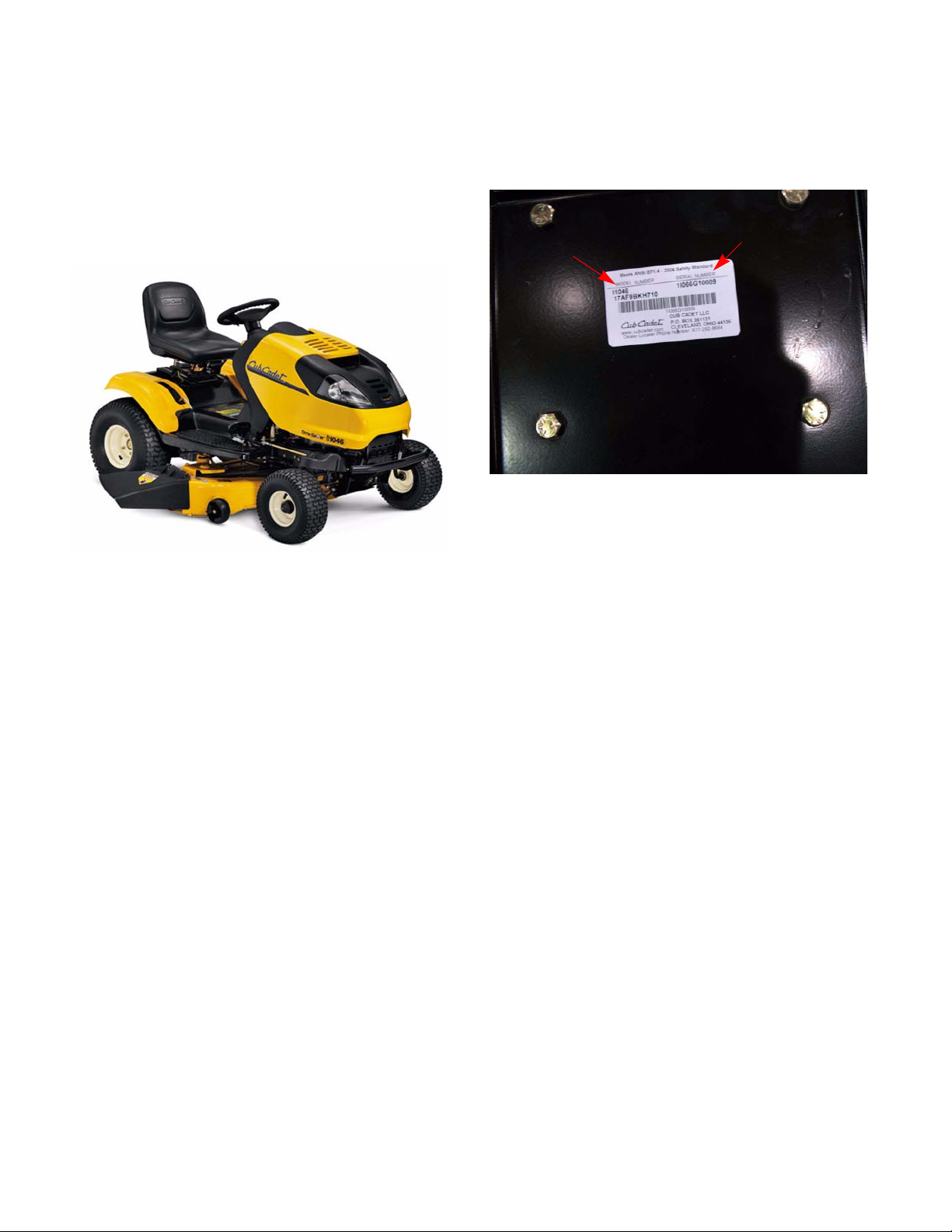
Model and Serial Numbers
The model and serial number tag can be found
under the seat. See Figure 1.2.
Serial number
Model number
Figure 1.2
The serial number is located to the right of the
model number as shown above. See Figure 1.2.
The model number is 17AF9BKH710. The break
down of what the number mean is as follows:
17.........................residential zero turn mower
...A.......................sales level
......F.....................engine code
........9...................frame
..........B................drive system
............K..............hood style
...............H...........deck (H = 46” K = 50”)
...................710....customer number
The serial number is 1J056G10005. The serial numbe r
reads as follows:
1...........................engineering level
..J.........................month of production (J = October)
.....05....................day of the month
.........6..................last digit of the year
...........G................plant it was built in
..............1.............assembly line number
.................0005.....number of unit built
2
Page 9
CHAPTER 2: ENGINE RELATED PARTS
ENGINE RELATED PARTS
This chapter will cover the engine accessories that
are manufactured by Cub Cadet.
IMPORTANT: The engine is manufactured by
Kohler. Refer to the Kohler manual for engine
specific service information.
Muffler
Remove the muffler by following these steps:
1. Remove the hood and bumper by following the
steps described in Chapter 4: Body/Chassis.
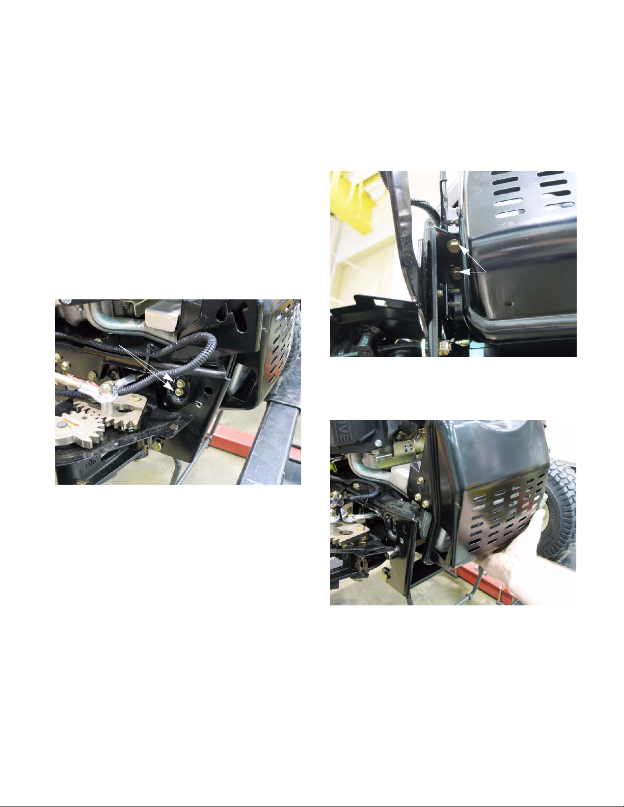
2. Remove the two screws on each side that hold
the muffler guard bracket. See Figure 2.1.
Remove these screws
3. Remove the hood pivot brackets by removing
the two screws that secure each one in place.
See Figure 2.2.
Remove these
screws
Figure 2.2
4. Pull the muffler cover and muffler out together.
See Figure 2.3.
Figure 2.1
Pull muffler foreword
Figure 2.3
NOTE: The muffler slides onto the exhaust
pipes. The heat of the exhaust makes the pipe s
expand and forms a seal with the muffler. Do not
weld or place a sealer between the muffler and
exhaust pipes.
3
Page 10
ENGINE RELATED PARTS
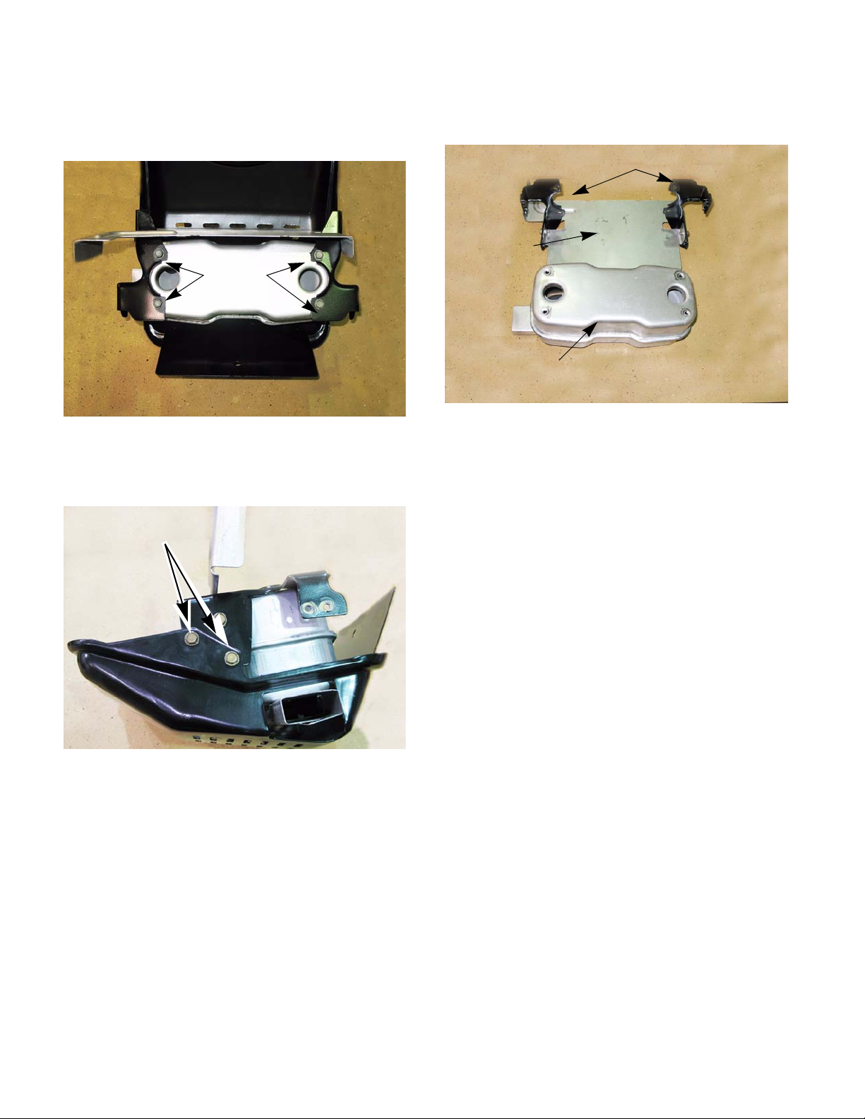
5. With the muffler on a work bench, remove the
four screws that fasten the muffler to the muffler
bracket. See Figure 2.4.
Remove these
screws
Figure 2.4
6. Remove the two screws that fasten the muffler
guard to the muffler bracket. See Figure 2.5.
Remove these screws
7. The muffler, muffler cover and the muffler
bracket can now be separated. See Figure 2.6.
Muffler brackets
Heat shield
Muffler
Figure 2.6
NOTE: The heat shield and muf fler bracket s can
be left together and handled as one part.
8. Install the muffler by following the above steps in
reverse order.
Figure 2.5
4
Page 11
ENGINE RELATED PARTS
Exhaust pipes
The exhaust pipes are manufactured by Cub
Cadet. To remove/replace the exhaust pipes:
1. Remove the muffler following the steps
described in the previous section.
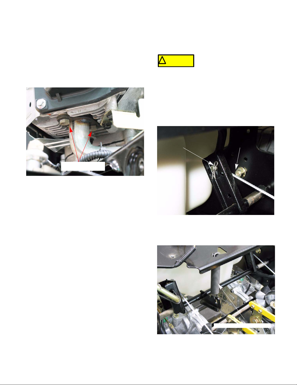
2. Remove the mounting bolts using a 1/2” wrench.
See Figure 2.7.
Remove these bolts
Fuel tank removal/replacement
Remove/replace the fuel tank by following these steps:
Gasoline and it vapors are
! CA UTION! CA UTION
system
1. Remove the deck.
2. Remove the fender by following the steps
described in Chapter 4: Body/Chassis.
3. Remove the hair pin clips retaining the deck lift
cables and disconnect the cables.
See Figure 2.8.
Hair pin clip
extremely flammable. Use common
sense when working around the fuel
Deck lift cable
Figure 2.7
3. DIscard the old exhaust gaskets. Clean all gasket material from the cylinder head (and exhaust
pipe if it is being reused.
4. Using new gaskets, install the exhaust pipes following the above steps in reverse order.
Figure 2.8
4. Unhook the deck lift assist spring.
See Figure 2.9.
Deck lift assist spring
Figure 2.9
5
Page 12
ENGINE RELATED PARTS
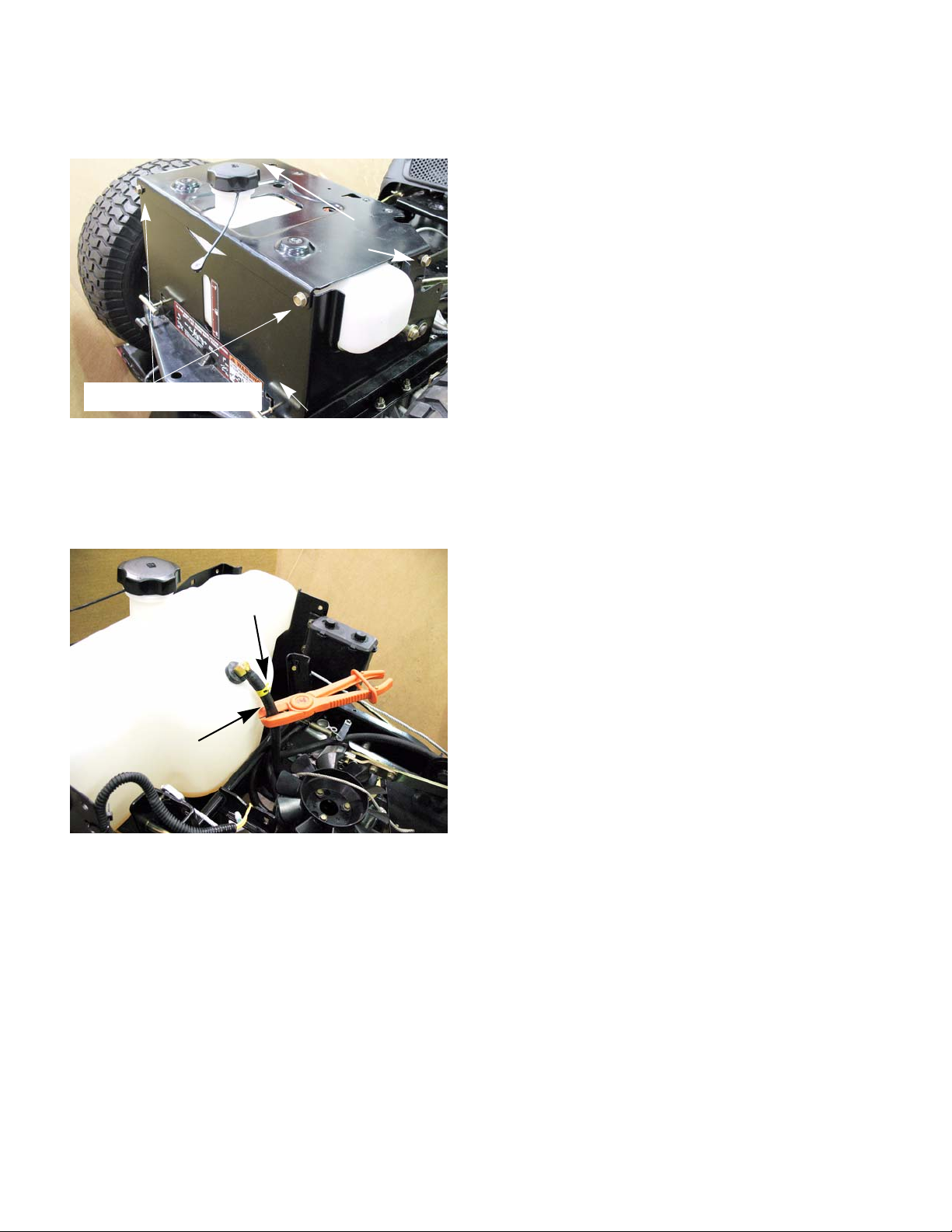
5. Remove the two screws and two nuts that fasten
the seat box cover. See Figure 2.10.
Remove these screws
Remove these screws
Seat box
Figure 2.10
6. Remove the seat box cover.
7. Clamp the fuel line. See Figure 2.11.
Fuel line clamp
Fuel line
Figure 2.11
8. Remove the fuel line clamp and slide the fuel
line off.
NOTE: The fuel tank has a barbed fitting. Anytime a fuel line is removed from a barbed fitting it
should be replaced because of the damag e
caused to the fuel line liner.
9. Lift the fuel tank out of the seat box.
10. Install the fuel tank by following the above steps
in reverse order.
11. Test run the tractor and check for leaks before
returning to service.
6
Page 13
CHAPTER 3: BRAKES
BRAKES
Brake system description
The I-series tractors have two braking systems
available based on which transmission is used.
HydroGear transmissions use a disc type brakes. The
IVT transmission uses an external drum brake system.
For HydroGear transmissions:
• The brakes are located on each transmission.
• They are activated by pressing on the brake
pedal.
• The brake pedal is attached to a brake cross
shaft assembly. This will pull on the two brake
rods.
• The brake rods are attached to the cam arms, in
the brake calipers, by over travel springs.
• When the cam arms are pulled forward they
push on the brake pins by a cam action applying
pressure to the brake pads.
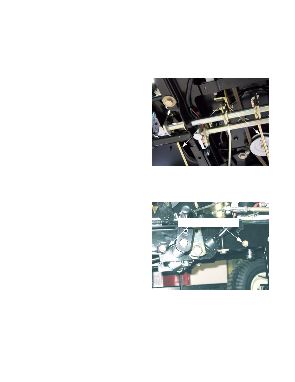
• The brake cross shaft assembly also has a link
that is connected to the drive belt idler pulley
bracket. When the brakes are applied, the idler
pulley is pulled away from the drive belt. This detensions the belt, disengaging drive to the transmissions. See Figure 3.1.
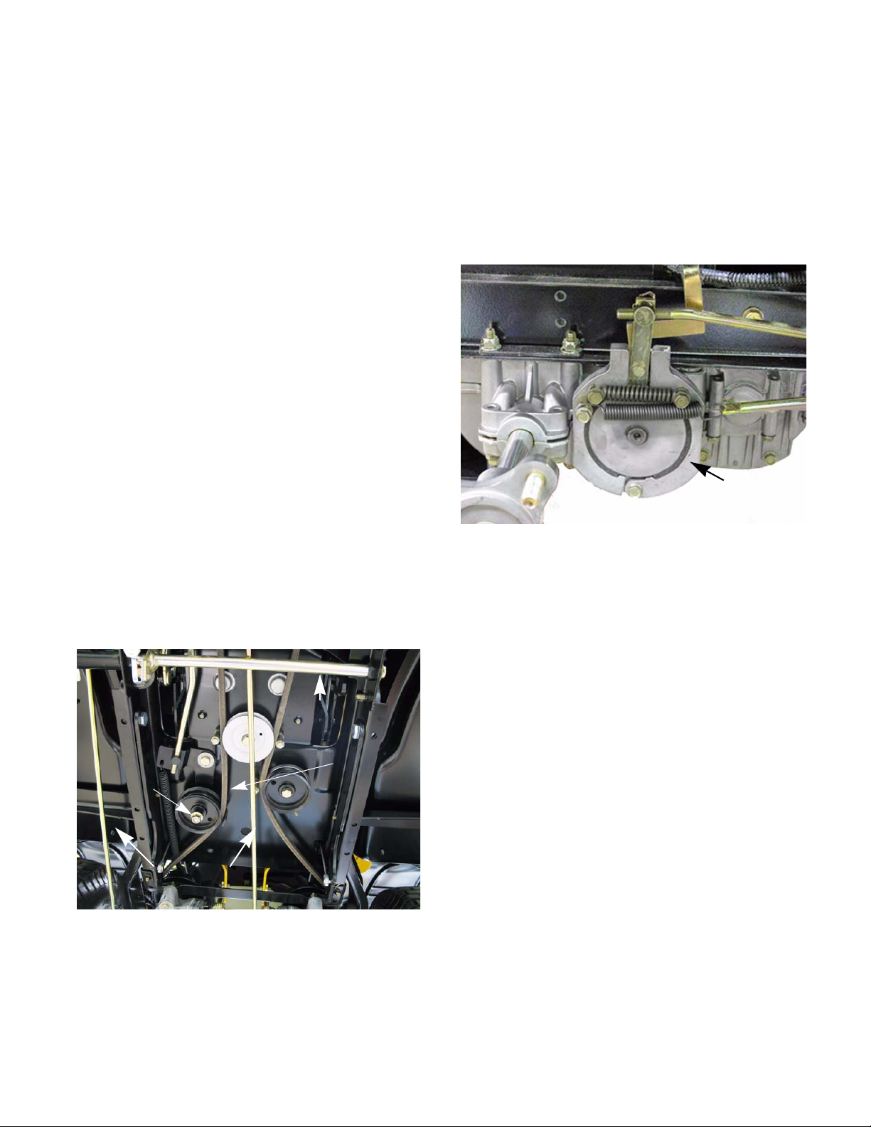
For the IVT transmission:
The IVT transmission has two drop axles. On each
drop axle there is an external drum brake.
See Figure 3.2.
Brake
Figure 3.2
• The brakes are applied whenever the drive
pedal is released.
• Depressing the brake pedal will disengage the
drive belt and apply extra force to the rear
shoes.
Idler pulley
Brake rods
Drive pedal shaft
Figure 3.1
• The idler pulley bracket has a gas charged
dampener attached to it. This dampener will
smooth out the engagement of the drive belt
when the brake pedal is released.
Belt
de-tensioned
7
Page 14
BRAKES
Brake adjustment - HydroGear transmissions
NOTE: Whenever performing a brake adjust-
ment, inspect the brake components for signs of
wear or damage.
1. Block the front wheels.
2. Lift and safely support the rear of the tractor.
See Figure 3.3.
Place jack stands here
Figure 3.3
5. Back the castle nut off a few turns using a 9/16”
wrench.
NOTE: Even if the brakes are set to the correct
clearance, inserting a feeler gauge between the
rotor and the brake puck can be very difficult.
Loosen the castle nut first, then insert the feeler
gauge and tighten the nut to set the pro per clearances
6. Insert a .030” (0.8 mm) feeler gauge between
the brake rotor and the outboard brake puck.
See Figure 3.5.
0.030” feeler
gauge
NOTE: Make sure the brake and parking brake
are released.
3. Remove the rear wheels.
4. Remove the cotter pin locking the castle nut on
the brake caliper. See Figure 3.4.
Castellated nut
Figure 3.4
Cotter pin
Figure 3.5
NOTE: The tolerance for the brake clearance is
.020” - .040” (0.5 - 1.0mm). The .030 feeler
gauge will set the clearance at the midpoint.
7. Tighten the nut until there is a slight drag on the
feeler gauge when sliding it out.
NOTE: For even braking, both sides should be
set to the same clearance.
8. Install a new cotter pin.
9. Repeat same procedure on the other side.
10. Put the wheels back on. Tighten the lug nuts to a
torque of 53 - 60 ft lbs. (72 - 81 Nm).
11. Take the tractor off of the jack stands.
12. O pen the by-pass valves and check the parking
brake before returning the tractor to service.
• With the brakes released, the tractor should
have only hydraulic drag when it is pushed.
• With the brakes engaged, the wheels should
slide before they rotate when the tractor is
pushed.
8
Page 15
BRAKES
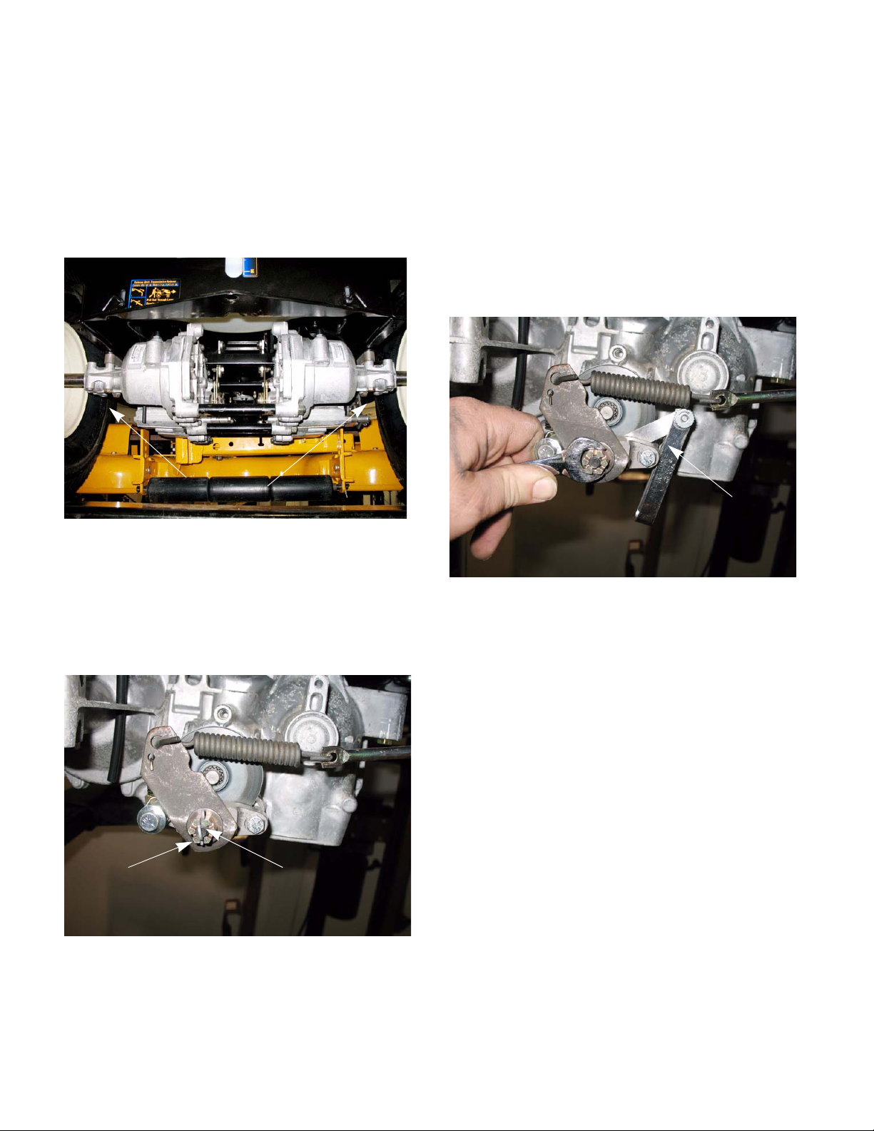
Brake adjustment - IVT transmissions
To adjust the brakes on IVT transmission:
1. Lift the rear of the tractor and safely support it
with a pair of jack stands.
2. Remove the rear wheels with a 3/4” wrench.
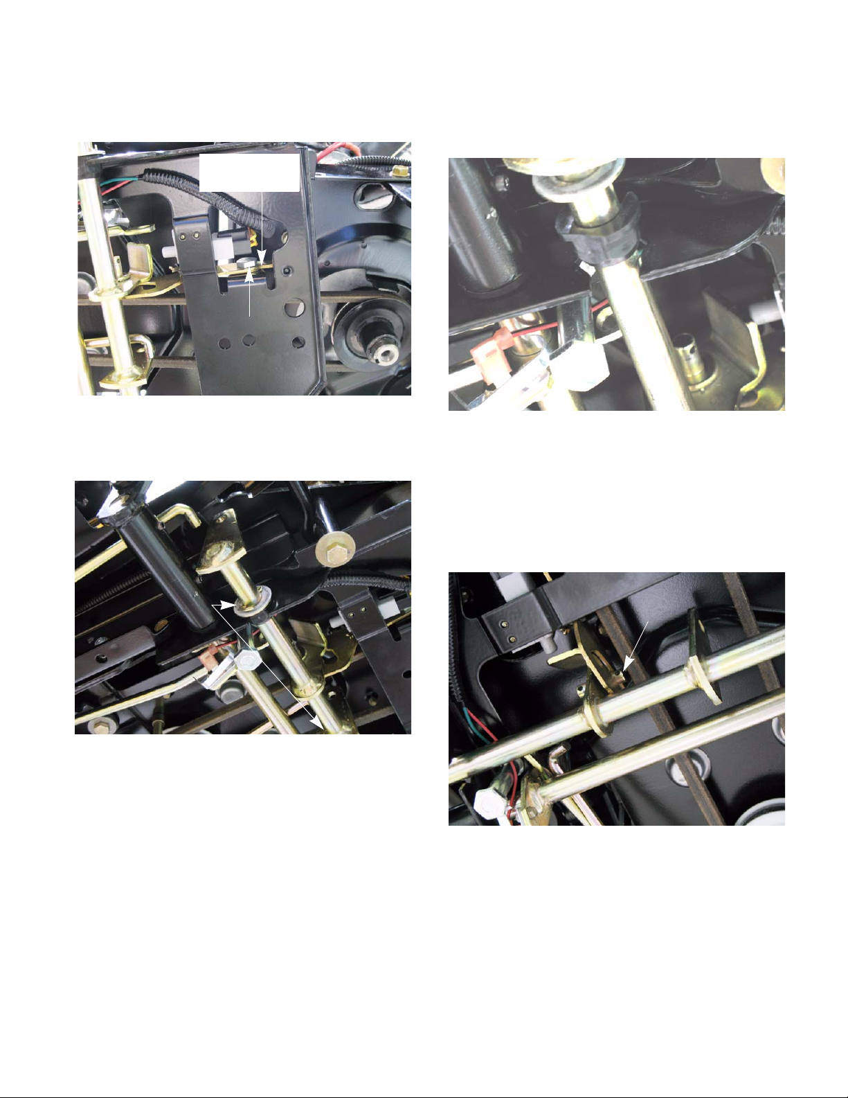
3. Release the parking brake.
4. Remove the cotter pin that retains the ferrule of
the drive control rod. See Figure 3.6.
brake disengagement block
Drive control rod
Ferrule
Brake puck/rotor replacement - HydroGear Trans-
missions
On HydroGear transmissions, the brake pucks are
a wearing part that will need to be serviced from time to
time. If a tractor is operated with the parking brake
dragging, the pucks will wear out rapidly and the brake
rotor will develop hot spots. If the tractor is operated
long enough, the rotor may have grinding marks on it
with excessively worn pucks.
If the rotor shows hot spots or any
! CA UTION! CA UTION
ure to do so can result in the failure of the brakes
The brake pucks and the rotors are serviced at the
same time. To service the brake pucks:
1. Jack up the tractor and remove the rear wheels
as described in the previous section.
2. Make sure the brakes are released.
3. Disconnect the brake rod spring. See Figure 3.7.
other signs of damage, including
warpage, it must be replaced. Fail-
Figure 3.6
5. Slide the ferrule of the drive control rod out of the
brake disengagement block.
NOTE: Once the control rod is disengaged, the
springs will clamp the brake shoes against the
drum. This will automatically center the disengagement block.
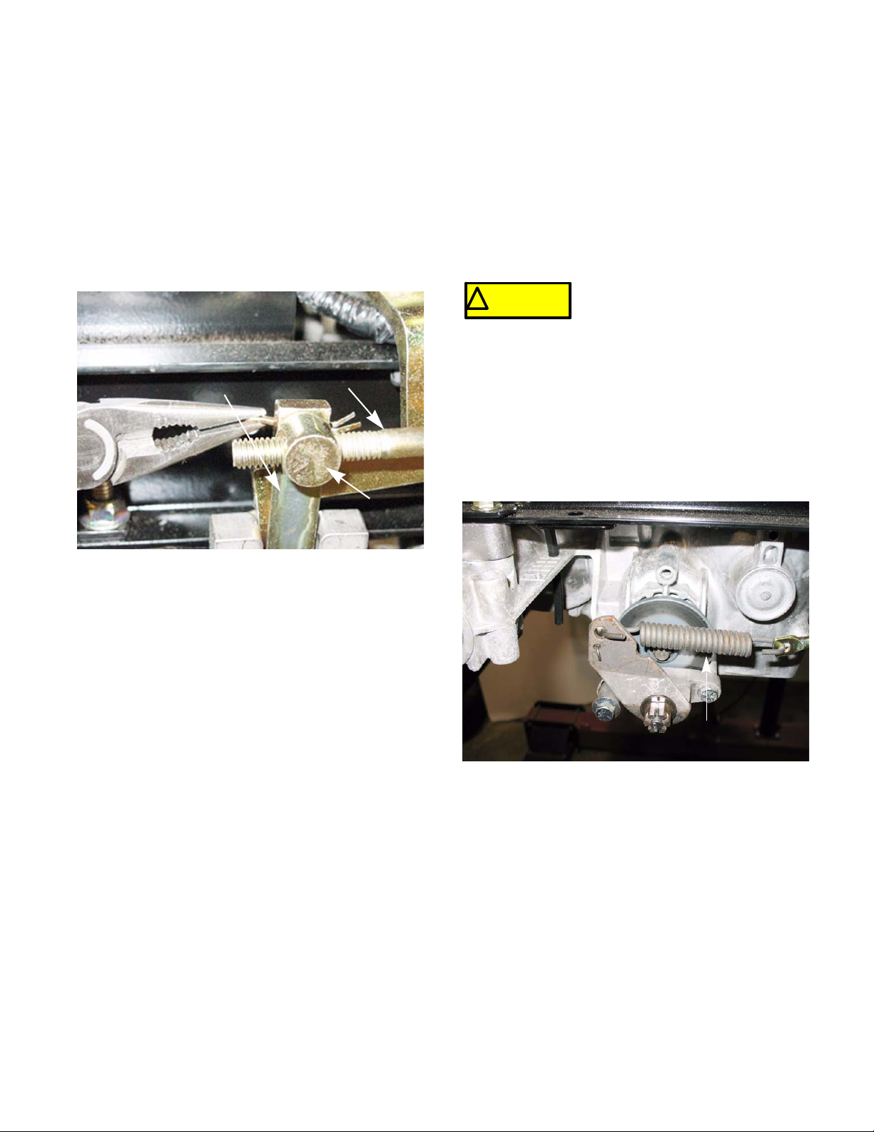
6. Adjust the ferrule until it slides into the hole in
the disengagement block with out applying pressure to it.
7. Install a new cotter pin into the ferrule to secure
it to the disengagement block.
8. Repeat the steps 4 - 6 on the other side of the
tractor.
9. Install the rear wheels. Tighten the lug nuts to a
torque of 53 - 60 ft lbs. (72 - 81 Nm).
10. Take the tractor off of the jack stands.
11. Test drive the tractor in a safe area before
returning it to service.
Disconnect this spring
Figure 3.7
9
Page 16
BRAKES
4. Loosen the rear mounting bolt. See Figure 3.8.
Remove this
bolt
Loosen this bolt
Figure 3.8
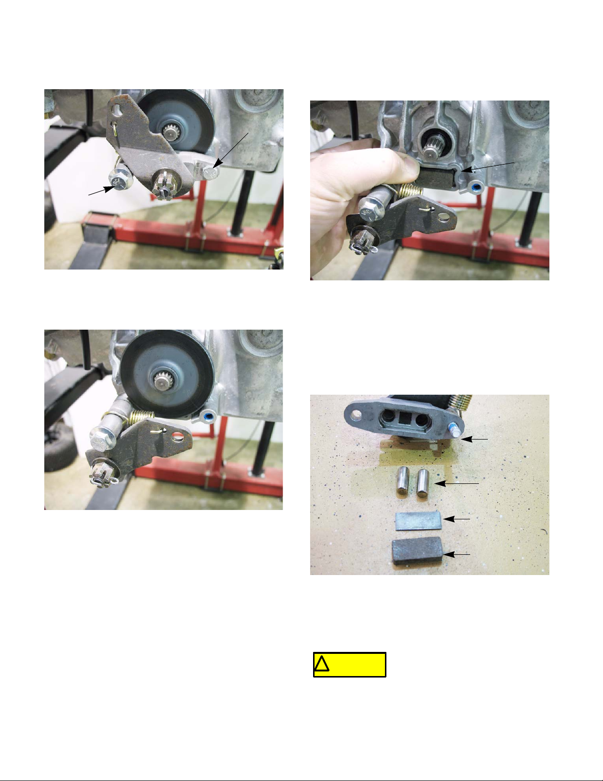
5. Remove the front mounting bolt, allowing the
caliper to swing down. See Figure 3.9.
7. Slide the brake rotor off to reach the inboard
brake puck. See Figure 3.10.
Inboard brake
puck
Figure 3.10
8. Remove the caliper for inspection when servicing the brake pucks. To do this, remove the rear
bolt loosened in step 4.
9. With the caliper on a work bench, remove the
brake puck, backing plate and the two brake
pins. See Figure 3.11.
Figure 3.9
6. The outboard brake puck should fall out when
the brake caliper swings down. If it did not, it can
be removed now.
Brake caliper
Brake pins
Backing plate
Brake puck
Figure 3.11
10. Check for free movement of the brake pins. A
dry lubricant can be used on the brake pins sparingly.
Never put grease or anti-seize on
! CA UTION! CA UTION
action of the pucks.
brake pins. It can migrate to the
brake pucks, preventing the braking
10
Page 17
BRAKES
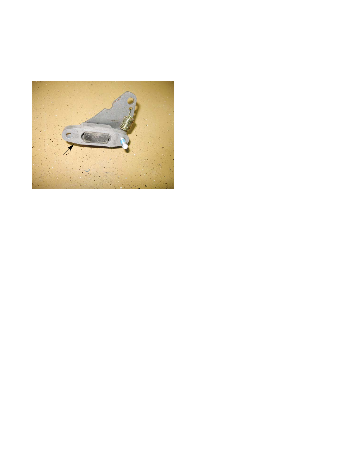
11. Slide the brake pins into the caliper.
12. Place the backing plate in the caliper.
13. Place a new puck into the caliper.
See Figure 3.12.
Brake caliper re-assembled
Figure 3.12
NOTE: A piece of scotch tape may be used to
hold the new brake pucks in place for assembly.
The tape will grind away when the brakes are
applied.
16. Mount the brake caliper to the transmission.
Apply a small amount of releasable thread locking compound such as Loctite® 242 (blue) to the
mounting bolts and tighten to a torque of 80 120 in-lbs (9 - 13.5Nm).
17. Reconnect the brake rod spring.
18. Adjust the brakes as described in the previous
section.
19. Put the wheel on.
20. Repeat steps 4-19 on the other side.
21. When both sides are completed and both wheels
are back on, take the tractor off of the jack
stands.
22. O pen the by-pass valves and check the parking
brake before returning the tractor to service.
• With the brakes released, the tractor should
have only hydraulic drag when it is pushed.
• With the brakes engaged, the wheels should
slide before they rotate when the tractor is
pushed.
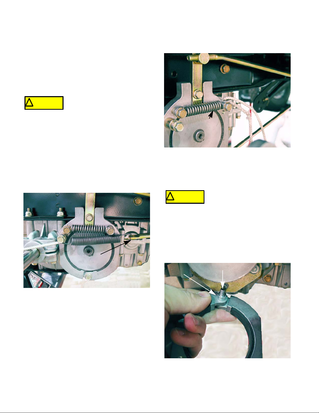
14. Place a new brake puck into the recess in the
transmission. Use a piece of scotch tape to hold
it in place.
15. Slide the brake rotor in place, shoulder out.
11
Page 18
BRAKES
Brake shoes/drum - IVT transmissions
On IVT transmissions, the brake shoes and drums
are the wearing parts that will need to be serviced from
time to time. If a tractor is operated with the parking
brake dragging, the shoes will wear out rapidly and the
brake drum will develop hot spots. If the tractor is operated long enough, the drum may have grinding marks
on it with excessively worn shoes.
If the drum shows hot spots or any
! CA UTION! CA UTION
ure to do so can result in the failure of the brakes
IMPORTANT: The brake shoes and the drums
must be replaced at the same time.
To service the brakes:
1. Jack up the tractor and remove the rear wheels
as described in the previous section.
2. Make sure the brakes are released .
3. Disconnect the brake rod spring.
See Figure 3.13.
other signs of damage, including
warpage, it must be replaced. Fail-
4. Disconnect the brake shoe spring.
See Figure 3.14.
Brake shoe
spring
Figure 3.14
NOTE: There is a lot of tension in the brake
shoe springs. A piece of starter rope can be
used to remove the spring.
Do not remove the screws to dis-
! CA UTION! CA UTION
and can cause the screw to become a projectile as it is
being removed.
connect the brake shoe springs.
The springs are under high tension
Brake rod
Figure 3.13
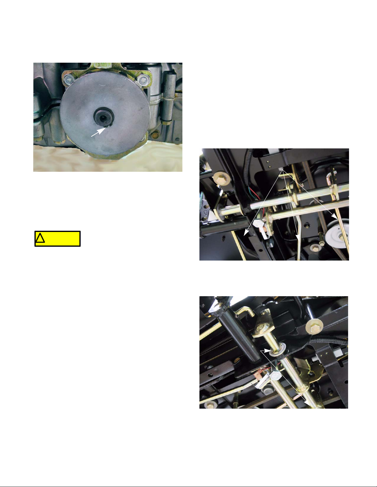
5. Remove the pivot bolt at the bottom of the brake
shoes.
NOTE: There is a spacer behind the shoes that
will fall out as the pivot bolt is removed.
See Figure 3.15.
Spacer
Pivot bolt
Figure 3.15
12
Page 19
BRAKES
6. Remove the snap ring that secures the drum
with a pair of snap ring pliers. See Figure 3.16.
Remove the snap ring
Figure 3.16
7. Install the drum and shoes by following step s 1 7 in reverse order.
8. Repeat steps 1-8 on the other side of the tractor.
Brake cross shaft assembly
The brake cross shaft assembly for the HydroGear
transmissions and the IVT transmissions are not the
same. The procedure to service them are the same.
The brake cross shaft assembly is supported by
two bushings. Excessive movement in the brak e cro ss
shaft assembly may be an indication that the bushings
are worn out.
To replace the brake cross shaft bushings:
1. Remove the cotter pins that retain the three
brake rods. Slide the brake rods out of the brake
cross shaft assembly. See Figure 3.17.
Brake rods
Never put grease or anti-seize on
! CA UTION! CA UTION
braking surfaces, preventing the braking action of the
shoes.
9. Test drive the tractor in a safe area before
returning it to service.
the brake shoe pivot screw or the
drum splines. It can migrate to the
Figure 3.17
2. Remove the cotter pins on each end of the brake
cross shaft. See Figure 3.18.
Remove cotter pins
13
Figure 3.18
Page 20
BRAKES
3. Remove the right side bushing first. This will
allow the shaft to slide far enough to the lef t to let
the other bushing to come out.
4. Install new bushings by following the above
steps in reverse order.
NOTE: Do not put grease on the bushings.
Grease can trap dirt that will accelerate the wear
of the bushing.
5. Check the operation of linkage and test drive the
tractor in a safe area before returning to service.
To remove/replace the brake cross shaft assembly:
1. Remove the brake pedal by removing the two
screws using a 1/2” wrench.
2. Remove the cotter pins that retain the three
brake rods. Slide the brake rods out of the brake
cross shaft assembly. See Figure 3.19.
Brake rods
Figure 3.19
3. Remove the four screws (two on each side) that
hold the sub-frame in place and slide it down.
See Figure 3.20.
Remove these screws
Figure 3.20
14
Page 21
BRAKES
4. Loosen the shoulder bolt that the parking brake
plate pivots on. See Figure 3.21.
Parking brake
plate
Shoulder bolt
Figure 3.21
5. Remove the cotter pin from each end of the
brake cross shaft. See Figure 3.22.
6. Slide the split bushings out of their pockets in the
sub-frame, then pull them off of the brake cross
shaft assembly. See Figure 3.23.
Figure 3.23
7. Work the brake cross shaft ou t of the sub frame .
NOTE: Take care not to bend the parking brake
plate while working the brake cross shaft out.
Make sure the shoulder bolt is loose enough to
give the shaft clearance. The plate can be
removed if necessary. See Figure 3.24.
Remove cotter pins
Slide pin out of plate
Figure 3.22
Figure 3.24
8. Replace the brake cross shaft by following the
above steps in reverse order.
9. Test drive the tractor in a safe area before
returning to service.
15
Page 22

BRAKES
16
Page 23
CHAPTER 4: BODY/CHASSIS
BODY/CHASSIS
The hood
The I-series hood uses the same hood pivot sys-
tem as the 1000 series for easy removal.
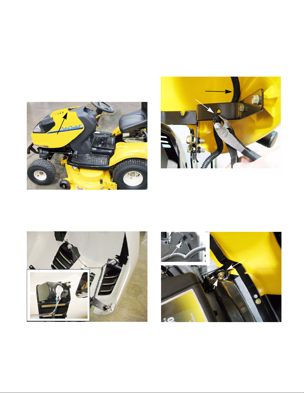
To remove the hood:
1. The hood is front-hinged. See Figure 4.1.
Lift here
Figure 4.1
2. Open the hood by lifting the rear edge to tilt it forward.
3. Disconnect the headlight wires. See Figure 4.2.
4. Cut the wire tie that secures the headlight harness to the hood. See Figure 4.3.
Headlight harness
Wire tie
Figure 4.3
5. The hood hinges on a pair of shoulder bolts on
each side that fit into slots in the hood bracket.
6. The hinge travel is limited by the top shoulder
bolt that fits into a channel in the hood bracket.
7. Open the hood far enough to align the tabs with
the slots, then lift the hood off of the tractor.
See Figure 4.5.
Inset: headlight detail
Figure 4.2
NOTE: The ground terminals and powe r te rm i-
nals on the headlights are two different sizes.
The green wires (ground) fit the larger terminals.
The red wires (power) fit the smaller terminals.
17
Slots
Bracket
Shoulder bolts
Figure 4.4
Page 24
BODY/CHASSIS
Bumper
I-series tractors come equipped with a fast attach
bumper. To remove the bumper:
1. Remove the two screws, one on each side, that
secures the bumper bracket. See Figure 4.5.
Remove screw
Bumper
Figure 4.5
Dash Removal
The dash for the I-series is easy to remove. There
are a few repair procedures, such as the cam angle
adjustment or replacing the steering gearbox, that
require the dash to be removed. The step s to remove it
are as follows:
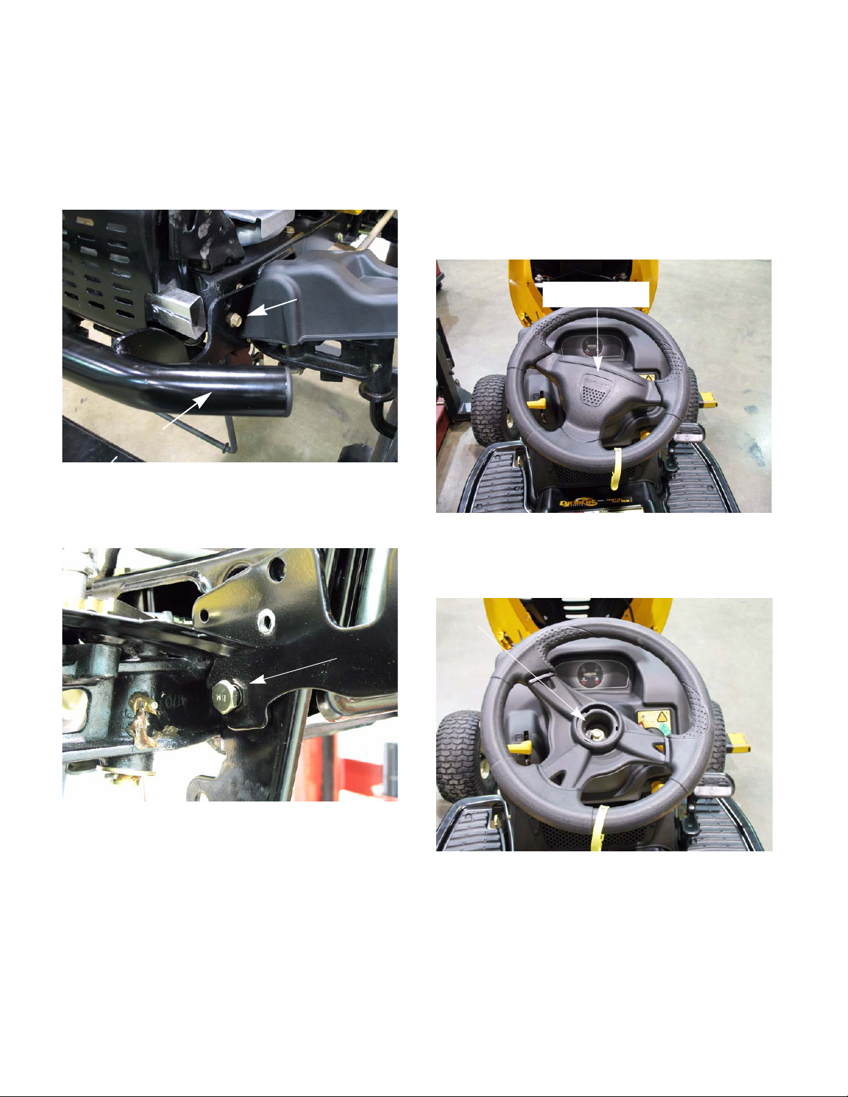
1. Remove the steering wheel:
1a. Remove the center cover. See Figure 4.7.
Center cover
2. Pull the bumper straight forward, sliding th e
bumper off of the shoulder bolts. See Figure 4.6.
Shoulder bolt
Figure 4.6
3. Install the bumper following the above steps in
reverse order.
Figure 4.7
1b. Remove the bolt with a 1/2” wrench.
See Figure 4.8.
Remove
this
bolt
Figure 4.8
NOTE: There is no puller needed for the steer-
ing wheel. Once the bolt is removed it will lift off
of the steering shaft.
18
NOTE: When replacing the steering wheel, lock
the steering gear box in neutral as described in
steering chapters (6A or 6B). This will make it
easier to center the steering wheel.
Page 25

BODY/CHASSIS
2. Remove the dash:
2a. Disconnect the key switch, module, PTO
switch and the hour meter.
See Figure 4.9.
Hour meter
PTO switch
Figure 4.9
2b. Disconnect the parking brake by removing
the hair pin clip and sliding the rod out of the
lever. See Figure 4.10.
2c. Remove the two screws attaching the dash
to the dash support. See Figure 4.11.
One on each side
Module and
key switch
Figure 4.11
2d. Remove the two screws in the cargo net
area, at the bottom of the dash.
See Figure 4.12.
Hair pin
clip
Rod
Figure 4.10
Remove these screws
Figure 4.12
NOTE: The cargo net was removed for a clearer
picture. Do not remove the net to remove the
dash.
NOTE: If removing the dash, disconnect the
throttle and choke cables at this point.
19
Page 26
BODY/CHASSIS
e
2e. Remove the screws at the bottom of the
dash, on each side. See Figure 4.13.
Screw removed
Figure 4.13
2f. The dash can now by lifted ov er the steering
shaft and placed to the side or on top of the
engine.
NOTE: If the throttle and choke cable are still
attached to the dash, care should be taken to
prevent damage to them when lifting the dash.
3. Install the dash by following the above steps in
reverse order.
Remove the fender
1. Remove the dash by following the steps
described in the previous section of this chapter.
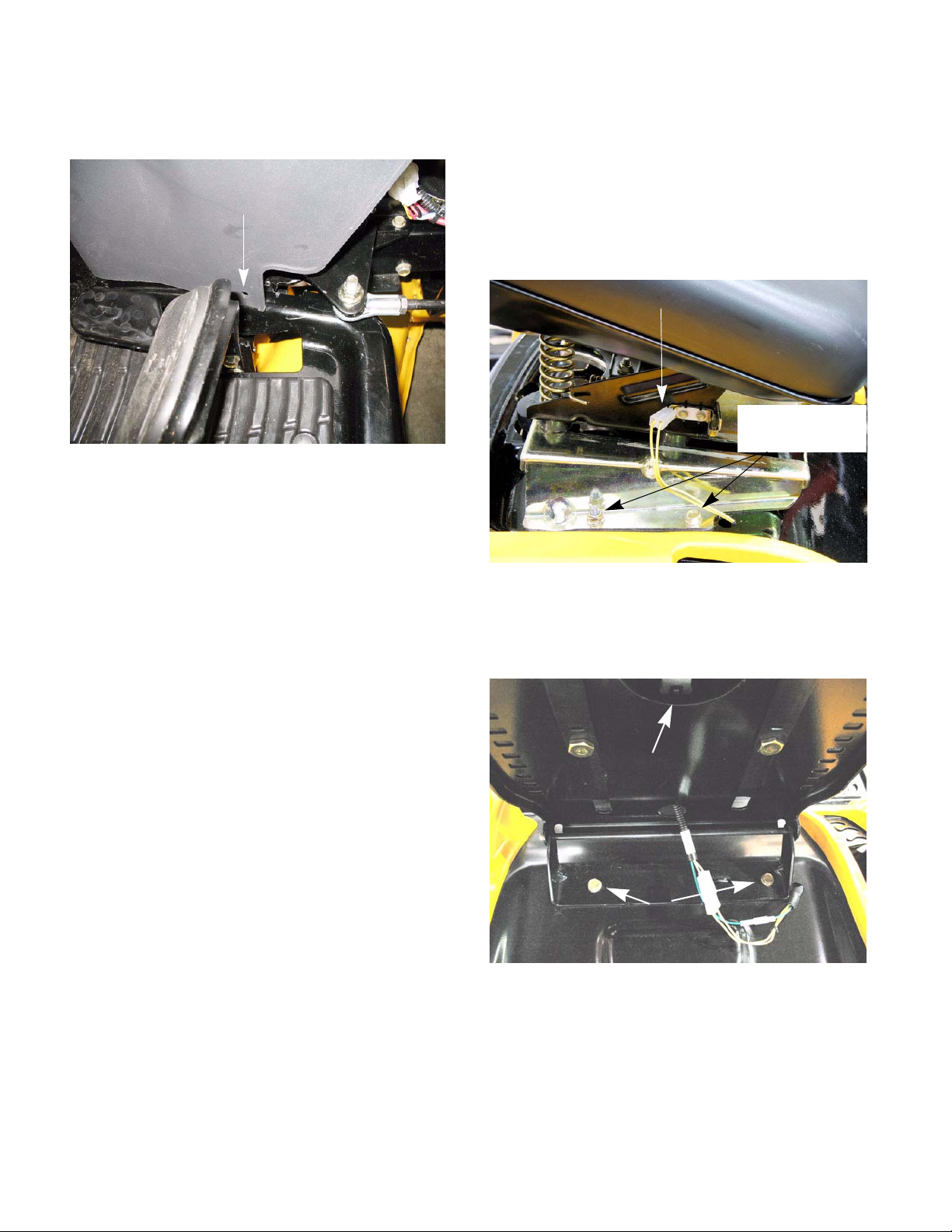
2. Disconnect the wires to the seat switch.
NOTE: Tractors built prior to 2008 have two yel-
low wires that go to a switch on the side of the
seat bracket. See Figure 4.14.
Seat switch wires
Remove the nut
and bolt to remov
seat
Figure 4.14
NOTE: Tractor built from 2008 to present have
two yellow wires and a green wire that go to a
switch inside the seat.
Seat switch
Seat bracket
mounting screws
Figure 4.15
NOTE: When reconnecting the wires, the posi-
tion of the two yellow wires does not affect the
20
operation of the tractor.
3. Remove the seat bracket and seat as one piece.
4. Remove the grip from the deck lift handle.
Page 27
BODY/CHASSIS
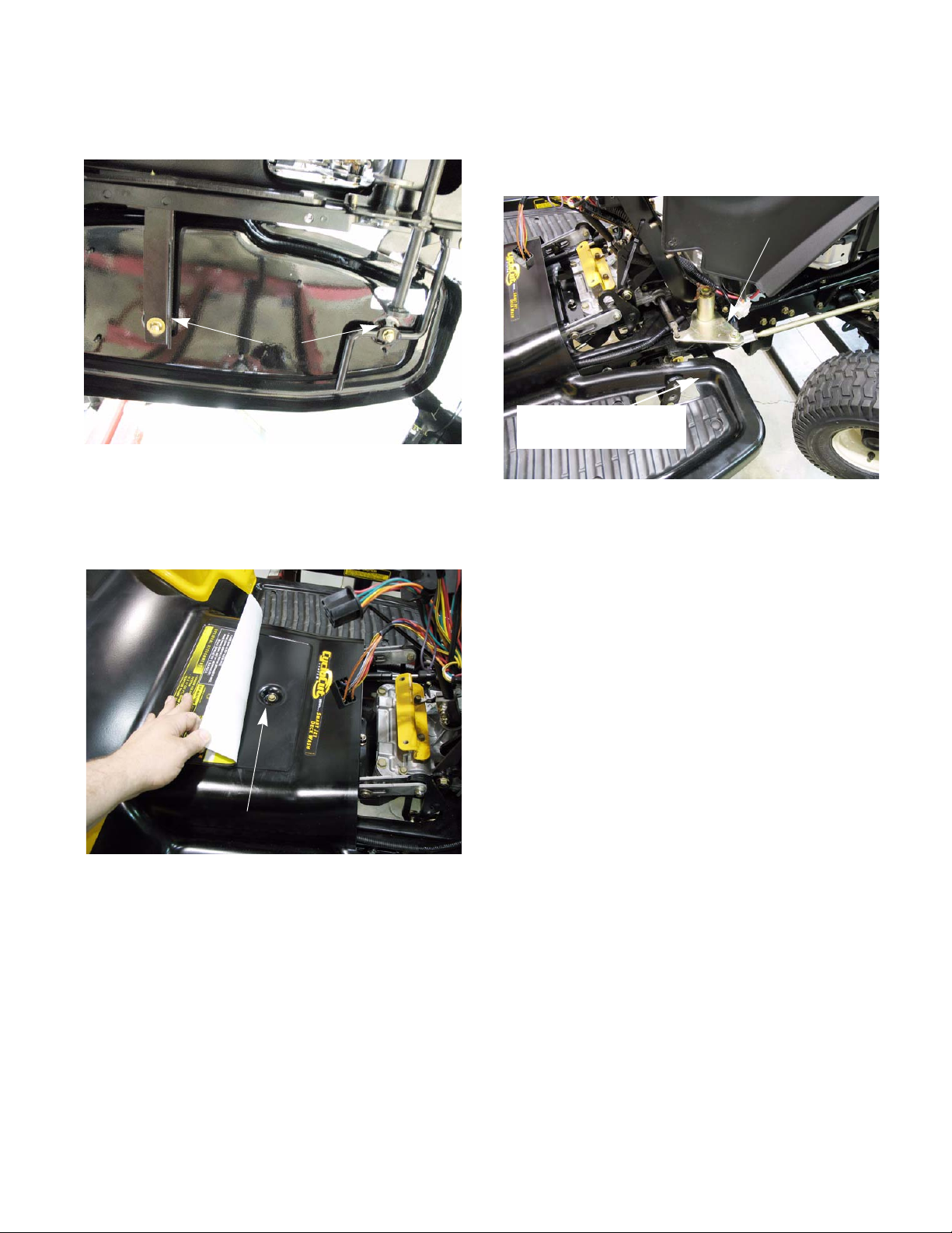
5. Remove the nuts from the under side of the foot
rests. See Figure 4.16.
Remove these nuts
Figure 4.16
6. Remove the brake and drive pedals.
7. Remove the screw from the center of the fender.
See Figure 4.17.
10. Place the steering wheel on the steering shaft.
Turn the wheels to the left and right to allow the
fenders to clear the steering arm assembly.
See Figure 4.18.
Steering arm assembly
Place some tape
here to protect the paint
Figure 4.18
NOTE: When lifting the fender off of the tractor,
clear the left side first and rotate the fender to
clear the deck lift lever.
Remove this screw
Figure 4.17
8. Remove the fuel cap.
9. Standing behind the tractor , lif t the fender up till it
clears the studs for the seat.
1 1. Install the fender by following the previous steps
in reverse.
21
Page 28

BODY/CHASSIS
22
Page 29
DRIVE SYSTEM-HYDROGEAR
CHAPTER 5A: DRIVE SYSTEM - HYDROGEAR TRANSMISSIONS
There are two drive systems available for the Iseries tractor. One system uses two HydroGear transmissions. The other system uses an Infinitrak full-toroidal Infinitely Variable Transmission (IVT). Th is chap ter
will cover the HydroGear version of the tractor.
The HydroGear version of this tractor uses two
EZT transmissions. The transmission control linkages
work in unison with the steering linkage to create the
zero-turn feature. The neutral adjustments for the
transmissions and the transmission links are covered
in chapter 6A: Steering - HydroGear.
The Hydro-gear shop manual for the EZT transmissions is form number BLN-52622.
Drive belt
The drive belt is the most common drive system
component that will need attention. To remove/replace
the drive belt:
1. Remove the deck as described in chapter 8:
Cutting Decks and Lift Shaft.
2. Set the parking brake.
3. Unplug the electric PTO harness.
See Figure 5A.1.
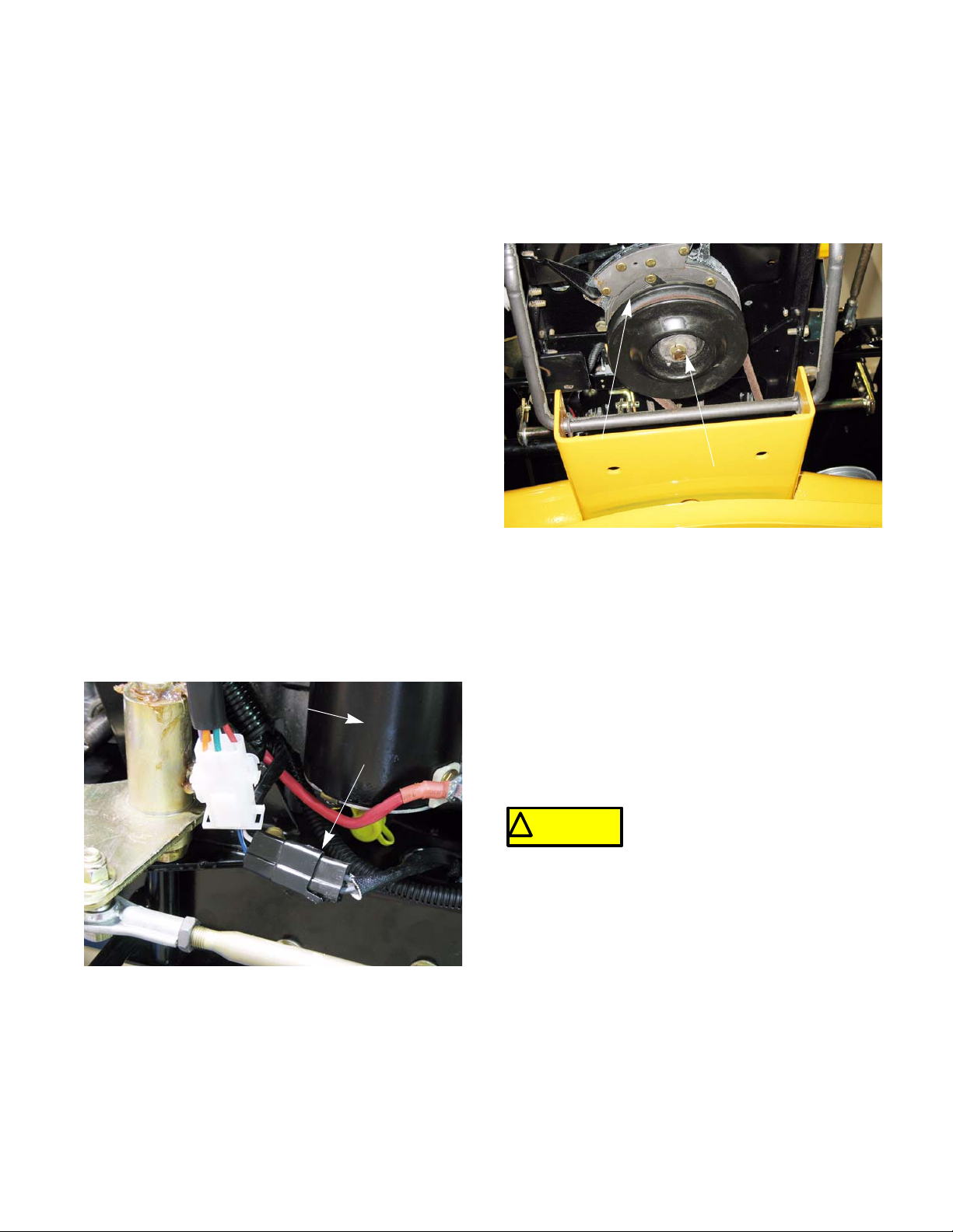
4. Unbolt the electric PTO using an impact wrench
and a 5/8” socket. See Figure 5A.2.
PTO clutch
Remove bolt with an impact wrench
Figure 5A.2
NOTE: If the PTO clutch will not slide off of the
crankshaft, thread the bolt half way into the
crankshaft. Make sure the belt keeper is in place
to prevent the clutch from rotating. Start the
engine and turn the PTO on and off several
times to shake it loose.
Starter
PTO connector
Figure 5A.1
NOTE: If the PTO will not come off using the
steps above, remove the engine mounting bolts
and slide the engine back. This will give enough
clearance to slide the belt off of the engine pulley.
Cub Cadet belts are designed to fit
! CA UTION! CA UTION
prevent the de-clutching mechanism from working
properly when the brakes are applied.
our equipment and are not standard
lengths. Use of a non-OEM belt may
23
Page 30
DRIVE SYSTEM-HYDROGEAR
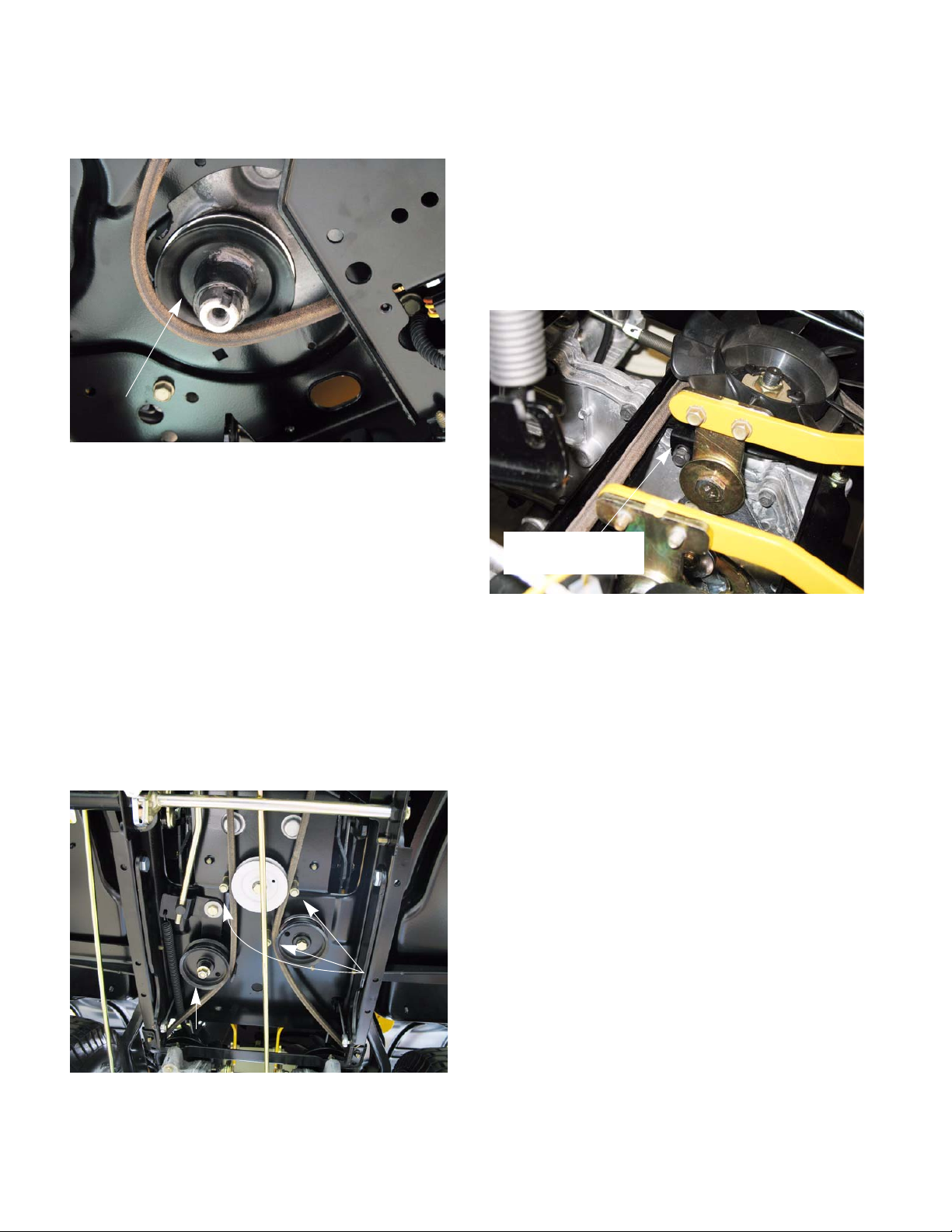
5. Slide the engine pulley down far enough to slip
the belt off of the pulley. See Figure 5A.3.
Engine pulley
Figure 5A.3
NOTE: Note the direction of the key in the
engine pulley. It should be facing down. If the
pulley is installed upside down, the belt alignment will be off.
NOTE: When installing the engine pulley and
electric PTO, coat the crank sh aft with anti-seize.
This will ease pulley and clutch removal in the
future.
NOTE: If the engine pulley is seized to the
crankshaft, the engine bolts can be removed to
slide the engine to the rear. This will provide
enough clearance to remove the belt.
7. Work belt off of the idler pulleys.
NOTE: It may be necessary to loosen the move-
able idler pulley to get the belt to clear the belt
guide on the idler bracket. See Figure 5A.4.
8. The transmission brace doubles as a belt
keeper. Remove the two screws that hold the
transmission brace to the transmission. Slide the
brace to the rear of the tractor to make enough
clearance to remove the belt. See Figure 5A.5.
Remove this
screw on each side
Figure 5A.5
9. Work belt around the transmission pulleys and
fans.
NOTE: Use care to prevent damage to the fans
when removing the belt.
6. Remove the three belt guides near the idler pulleys. See Figure 5A.4.
Belt guides
Moveable idler
Figure 5A.4
24
Page 31

DRIVE SYSTEM-HYDROGEAR
10. Remove the two screws that hold the transmission links to the shifter plate. See Figure 5A.6.
Transmission link
Remove these screws
Figure 5A.6
11. The belt can now be snaked out of the tractor.
12. Install the belt following the above steps in
reverse order.
Belt adjustment
The drive belt is tensioned by a spring loaded
moveable idler pulley. When the brakes are applied,
the drive belt is de-clutched. An adjustable linkage connects the tensioner pulley to the brake shaft. A brake
link that is out of adjustment will prevent the moveable
idler from correctly tensioning and de-tensioning the
belt.
As the belt wears and stretches, the moveable idler
needs to push the belt in further to keep proper belt
tension. To do this, the ferrule at the end of the brake
link needs to be at the middle of the slot in the idler pulley bracket. To adjust this brake link:
NOTE: The belt must be on when performing
this adjustment.
1. Release the parking brake.
2. Remove the deck as described in chapter 8 Cut-
ting Decks and Lift Shaft.
3. Remove the cotter pin and washer from the fer-
rule. See Figure 5A.7.
NOTE: Tighten the electric PTO clutch bolt to a
torque of 450 - 600 in-lbs (51 - 68 Nm).
13. Test drive the tractor before returning to service.
Cotter pin
Ferrule
Figure 5A.7
25
Page 32

DRIVE SYSTEM-HYDROGEAR
4. Slide the ferrule out of the idler bracket.
See Figure 5A.8.
Washer
Slot
Figure 5A.8
5. Adjust the ferrule so that it lines up with the rear
of the slot and slides in without pulling on the
spring. See Figure 5A.9.
Transmissions
The I-series tractor uses two EZT transmissions
from Hydro-gear. The transmissions can be removed
separately. To remove a transmission:
NOTE: The transmission model and serial number tags are located on the frame channel next
to the transmission that they refer to.
1. Remove the deck as described in chapter 8 Cut-
ting Decks and Lift Shaft.
2. Remove the drive belt as described previously in
this chapter.
NOTE: Leave the transmission links and the
transmission brace disconnected.
3. Lift and safely support the rear of the tractor.
4. Remove the rear wheels.
5. Unhook the by-pass rod. See Figure 5A.10.
Front of tractor
Figure 5A.9
6. Install the washer and a new cotter pin.
7. Test drive the tractor before returning to se rvic e.
8. Re-attach the deck.
Bad
spring
Unhook the spring
Figure 5A.10
6. Disconnect the brake rod by following the steps
described in Chapter 3: Brakes.
26
Page 33

DRIVE SYSTEM-HYDROGEAR
7. Remove the two bolts that thread into the cross
tubes. See Figure 5A.11.
Cross truss
Bolts
Figure 5A.11
8. Support the transmission to prevent it from fa lling while the mounting bolts are removed.
9. Remove the bolt holding the transmission to the
torque bracket. See Figure 5A.12.
10. Remove the two bolts that fasten the transmission to the frame. See Figure 5A.13.
Reinforcing strap
Spacer
Figure 5A.13
NOTE: The two transmission bolts pass through
a spacer and a reinforcing strap. When the bolt s
are removed, the spacer and strap can be
removed. See Figure 5A.13.
11. The transmission can now be removed from the
tractor.
Torque bracket
Bolt
Figure 5A.12
NOTE: There is a nut on the top side of the
torque bracket. Use a 7/16” wrench to hold it
while removing the bolt.
12. If replacing the transmission, remove the transmission pulley and fan assembly.
13. Remove the wheel hub assembly.
14. Install the hub on the new transmission and
tighten to a torque of 420 - 480 in-lbs (47.5 54Nm).
15. Install the transmission pulley and fan assembly
on the new transmission and tighten to a torque
of 300 - 460 in-lbs (34 - 52Nm).
16. Install the transmission by following steps 1 - 11
in reverse order.
17. Perform a neutral adjustment and wheel alignment by following the steps described in 6A:
Steering - HydroGear.
18. Test drive the tractor in a safe area before
returning to service.
27
Page 34

DRIVE SYSTEM-HYDROGEAR
Drive pedal shaft
To remove the drive pedal shaft:
1. Remove the deck as described in chapter 8 Cutting Decks and Lift Shaft.
2. Disconnect the link between the steering gear-
box and the bell crank on the drive pedal shaft.
See Figure 5A.14.
Steering gear box lever
Bell
crank
Link
Reverse switch
Figure 5A.14
6. Drive out the two roll pins that secure the drive
pedal bracket to the drive pedal shaft.
See Figure 5A.16.
Drive pedal bracket
Hex bushing
Figure 5A.16
7. Remove the hex bushing. See Figure 5A.16.
8. Slide the drive pedal shaft to the left to clear the
hole for the right side hex bushing.
See Figure 5A.17.
NOTE: It does not matter which side of the link is
disconnected.
3. Disconnect the reverse switch.
4. Remove and discard the cotter pin on the left
side of the drive pedal shaft. See Figure 5A.15.
Washer
cotter pin
Hex bushing
Figure 5A.15
Hole for hex bushing
Figure 5A.17
9. Install the drive pedal shaft by following the previous steps in reverse order.
10. Test drive the tractor before returning it to service.
5. Remove the washer and hex bushing.
See Figure 5A.15.
28
Page 35
CHAPTER 5B: DRIVE SYSTEM - IVT TRANSMISSION
DRIVE SYSTEM-IVT
There are two drive systems available for the Iseries tractor. One system uses two HydroGear transmissions. The other system uses an Infinitrak full-toroidal Infinitely Variable Transmission (IVT). This chapter
will cover the IVT version of the tractor.
The Infinitrak full-toroidal Infinitely Variable Transmission (IVT) removes the constraints of conventional
stepped ratio transmissions. Instead of using a system
of gears to determine the ratio range, the IVT uses a
variator that is made of a set of discs and rollers called
a “full toroidal” variator. In the IVT, the torque is controlled allowing optimization of the power train by allowing the engine to run at its most efficient RPM range
and stay there.
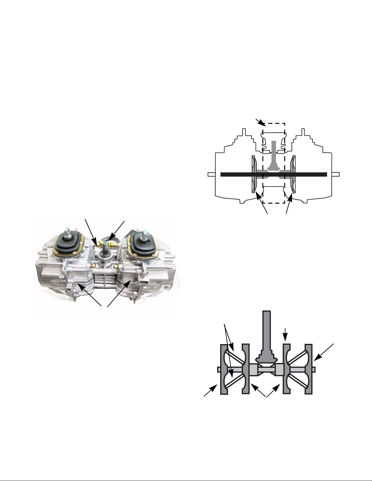
The IVT used on the I-series is a twin variator version. This means that there is one input and two outputs. See Figure 5B.1
“T” box
Input shaft
The power from the engine is transferred to the
transmission via a belt and pulleys. The power is
applied to a “T” box assembly. The “T” box output
drives the inner discs of the variator assemblies.
See Figure 5B.2
“T” box assembly
Inner disks
Figure 5B.2
Each inner disc drives a pair of rollers that drive the
output discs. The angle of the rollers determines the
speed of the output discs. When the rollers rides near
the center of the input discs, they are pressing against
the outer edge of the output discs. In this position, the
output disc will be turning at a much slower rate than
the input discs. See Figure 5B.3
Variators
Figure 5B.1
29
Rollers
Output disc
500 rpm
50 rpm
Input discs
Figure 5B.3
Page 36
DRIVE SYSTEM-IVT
NOTE: The RPM numbers used in figures 5B.2,
5B.3 and 5B.4 are not the actual measurements
of the disc speeds. They are just an example to
demonstrate the speed differences.
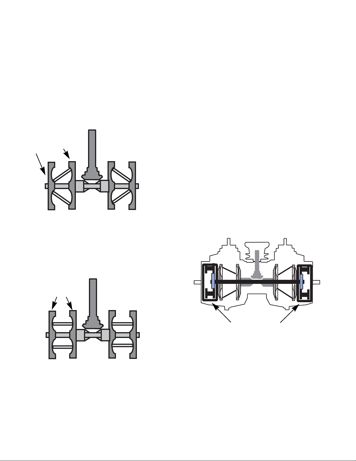
When the rollers rides near the outer edge of the
input discs, they are pressing against the center of the
output discs. In this position, the output disc will be
turning at a much faster rate than the input discs.
See Figure 5B.4
500 rpm
1,000 rpm
The key to making this work is a special traction
fluid that was developed for this transmission. A Traction fluid is a synthetic transmission fluid designed with
properties specifically for transmitting torque between
the discs and rollers.
Under normal load conditions this fluid acts like a
conventional lubricating fluid. When the fluid is subjected to extreme pressure, such as in the contact area
between the discs and rollers, the fluid changes to
exhibit its ElastoHydrodynamic Lubricant (EHL) properties. The EHL property of the traction fluid causes the
molecules in the fluid to become almost solid. This
increases the shear force transmitting properties of the
fluid.
The traction fluid in the contact area between the
rollers and discs turns into a semi-solid. This allows the
fluid to act like a gear tooth, transferring the torque
from the disc to the roller or vise versa. It also prevents
metal to metal contact extending the life of the moving
parts.
Figure 5B.4
When the rollers are in the neutral position o r in the
center of the disc valley, all of the discs are rotating at
the same speed. See Figure 5B.5
500 rpm
NOTE: Putting motor oil or hydraulic fluid in an
IVT transmission will destroy it.
Each of the variators are attached to a epicyclic,
also know as planetary, gear set. See Figure 5B.6
Epicyclic gear sets
Figure 5B.6
Figure 5B.5
30
Page 37

DRIVE SYSTEM-IVT
The output shaft of the T-box drives a sun gear in
the center of the planetary ge ars at the sa me sp eed a s
the input discs. The planetary gear carriers are
attached to the output discs. See Figure 5B.7
Output disk
Carrier
Planetary
gears
Epicyclic gear set
Figure 5B.7
The epicyclic gear set acts like an adding machine,
it subtracts the input (sun gear) speed from the output
(planetary gear carrier). See Figure 5B.8
Planetary gear
If the answer is positive, transmission drives in a
forward direction. If the answer is negative, the tra n s mission drives in reverse. If the answer is zero, the
transmission will have zero output and be in what is
known as a geared neutral state. See Figure 5B.9
Figure 5B.9
The answers from the epicyclic gear sets are collected by the transmission output shaf t s that a re dr iven
b the planetary gears. See Figure 5B.10
Carrier
Sun gear
Output shaft
Figure 5B.8
Figure 5B.10
31
Page 38

DRIVE SYSTEM-IVT
The transmission output shafts drive a pair of drop
axles assemblies.
The IVT transmissions are NOT serviceable.
The drop axles and brakes are serviceable and will be
covered in later sections of this chapter.
NOTE: Currently replacement traction fluid is n ot
available for purchase.
Drive belt
The drive belt is the most common drive system
component that will need attention. To remove/replace
the drive belt:
Cub Cadet belts are design to fit
! CAUTION! CAUTION
belt may prevent the de-clutching mechanism from
working properly when the brakes are applied.
1. Remove the deck as described in chapter 8:
Cutting Decks and Lift Shaft.
2. Lift and safely support the rear of the tractor.
3. Remove the three belt guides near the idler pul-
leys. See Figure 5B.11
our equipment and are not standard lengths. Use of a non-OEM
Belt Guides
32
Figure 5B.11
Page 39

DRIVE SYSTEM-IVT
4. Slide the retainer clip half way out of the dampener end using small flat head screw driver.
See Figure 5B.12
Moveable idler
Dampener end
Retainer clip
Figure 5B.12
5. Disconnect the dampener from the moveable
idler pulley bracket.
6. Disconnect the brake link from the moveable
idler pulley bracket.
9. Unplug the electric PTO harness.
See Figure 5B.14
Starter
PTO connector
Figure 5B.14
10. Unbolt the electric PTO using an impact wrench
and a 5/8” socket. See Figure 5B.15
7. Loosen the moveable idler pulley enough for the
belt to slip past the belt guide using a pair of
9/16” wrenches. See Figure 5B.13
Belt guide
Figure 5B.13
8. Slip the belt off of the idler pulleys.
PTO clutch
Remove bolt with an impact wrench
Figure 5B.15
NOTE: If the PTO clutch will not slide off of the
crankshaft, thread the bolt half way into the
crankshaft. Make sure the belt keeper is in place
to prevent the clutch from rotating. Plug in the
PTO clutch harness. Start the engine and turn
the PTO on and off several times to shake it
loose.
33
Page 40

DRIVE SYSTEM-IVT
11. Slide the engine pulley down far enough to slip
the belt off of the pulley. See Figure 5B.16
Engine pulley
Figure 5B.16
NOTE: If the engine pulley will not slide down
the crankshaft using the steps above, remove
the engine mounting bolts and slide the engine
back. This will give enough clearance to slide
the belt off of the engine pulley.
NOTE: Note the direction of the key in the
engine pulley. It should be facing down. If the
pulley is installed upside down, the belt alignment will be off.
NOTE: When installing the engine pulley and
electric PTO, coat the cran kshaft with anti-seize.
This will ease pulley and clutch removal in the
future.
NOTE: There is a spacer above the engine pulley. It is symmetrical and can not be put on
upside down. See Figure 5B.17
12. Remove the rear wheels.
13. Remove the transmission fan.
13a. Reach in through the wheel opening.
13b. Remove the three transmission fan screws
using a 5/16” wrench. See Figure 5B.18
Transmission
fan
Figure 5B.18
13c. Remove the transmission fan.
NOTE: Never use an impact wrench to remove
the transmission pulley. It will destroy the one
way bearing on the input shaft.
14. Remove the transmission belt guard.
14a. Remove the four screws using a 5/16”
wrench. See Figure 5B.19
Spacer
Belt guard
Engine
pulley
Figure 5B.19
14b. Remove the belt guard.
Figure 5B.17
34
Page 41

DRIVE SYSTEM-IVT
15. Slip the belt off of the transmission pulley.
16. Remove the belt from the tractor.
17. Install the belt following the previous steps in
reverse order.
Drive belt routing
Figure 5B.20
NOTE: Tighten the electric PTO clutch bolt to a
torque of 450 - 600 in-lbs (51 - 68 Nm).
18. Test drive the tractor before returning to service.
Belt adjustment
The drive belt is tensioned by a spring loaded
moveable idler pulley. When the brakes are applied,
the drive belt is de-clutched. An adjustable linkage connects the tensioner pulley to the brake shaft. A brake
link that is out of adjustment will prevent the moveable
idler from correctly tensioning and de-tensioning the
belt.
As the belt wears and stretches, the moveable idler
needs to push the belt in further to keep proper belt
tension. To do this, the ferrule at the end of the brake
link needs to be at the rear of the slot in the idler pulley
bracket.
NOTE: The moveable idler pulley has a dampener on it. The dampener allows a slow, smooth
engagement of the drive belt. See Figure 5B.21
Brake
link
Dampener
Moveable
idler
pulley
Figure 5B.21
The brake link is adjusted to the rear of the slot in
the moveable idler bracket. This allows the brake pedal
can return rapidly when the pedal is released, while the
dampener slows the engagement of the drive belt.
Operating the tractor with the idler
! CAUTION! CAUTION
the brake pedal is released.
To adjust this brake link:
NOTE: The belt must be on when performing
this adjustment.
1. Release the parking brake.
2. Remove the deck as described in chapter 8 Cut-
ting Decks and Lift Shaft.
35
pulley dampener removed will
result in the tractor lurching when
Page 42

DRIVE SYSTEM-IVT
3. Remove the cotter pin and washer from the ferrule. See Figure 5B.22
Cotter pin
Ferrule
Figure 5B.22
4. Slide the ferrule out of the idler bracket.
See Figure 5B.23
Transmissions
To remove the transmission:
1. Remove the deck as described in chapter 8 Cutting Decks and Lift Shaft.
2. Lift and safely support the rear of the tractor.
3. Remove the dash and fender by following the
steps described in Chapter 4: Body/Chassis.
4. Remove the rear wheels.
5. Remove the drive belt from the engine pulley
and the idler pulleys by following the procedures
described in the drive belt section of this chapter.
NOTE: The belt can stay on the transmission
pulley while the transmission is removed.
6. Unhook the by-pass rod spring on both sides of
the transmission. See Figure 5B.24
Washer
Slot
Figure 5B.23
5. Adjust the ferrule so that it lines up with the rear
of the slot and slides in without pulling on the
spring.
6. Install the washer and a new cotter pin.
7. Re-attach the deck.
8. Test drive the tractor before returning to se rvic e.
By-pass rod spring
Figure 5B.24
7. Disconnect the brake rods by following the steps
described in Chapter 3: Brakes.
8. Disconnect the drive control links:
36
Page 43

DRIVE SYSTEM-IVT
8a. Remove the hair and clevis pins.
See Figure 5B.25
drive control link
Hair pin clip
Clevis pin
Figure 5B.25
8b. Slide the drive control links off of the input
levers
9. Remove the two screws that fasten the expansion tank to the left side of the frame. See Figure
5B.26
10. Remove front mounting screw on each side of
the tractor using a 1/2” wrench.
See Figure 5B.27
Front mounting
screw
Figure 5B.27
NOTE: Support the transmission to prevent it
from falling while the mounting bolts are
removed.
11. Remove the two bolts that fasten the transmission to the frame and the support plate on each
side of the tractor. See Figure 5B.28
Expansion
tank
Figure 5B.26
NOTE: The seat frame plate was removed for a
clearer picture.
NOTE: Clamp off both of the lines going to the
expansion tank to help prevent loss of traction
fluid. Currently replacement traction fluid is not
available for purchase.
Support plate
Mounting bolts and nuts
Figure 5B.28
12. Lower the transmission out of the tractor.
NOTE: Avoid spilling traction fluid while moving
the transmission. Currently replacement traction
fluid is not available for purchase.
37
Page 44

DRIVE SYSTEM-IVT
13. If replacing the transmission assembly, remove
the transmission fan.
14. If only replacing the IVT (center section of the
transmission), remove the drop axles by following the procedures described in the drop axle
section of this manual.
15. Install the transmission by following the previous
steps in reverse order.
16. Perform a neutral adjustment and wheel alignment by following the steps described in 6B:
Steering - IVT.
17. Test drive the tractor in a safe area before
returning to service.
Drop axle assemblies
The drop axle assemblies on the IVT transmission
perform three functions:
• The drop axle assemblies are a gearbox that will
transmit the power of the IVT at a reduced speed
to the drive wheels.
• The drop axle contains a dog clutch assembly to
disconnect the transmission from the drive
wheel. This allowing the tractor to be pushed by
hand.
The drop axle assemblies are serviceable, sepa-
rately from the IVT.
To remove the drop axles:
1. Remove transmission assembly from the tractor
by following the procedures described in the previous section of this chapter.
2. Remove the eight screws the secure the transmission support bracket to the drop axles using
a 1/2” wrench. See Figure 5B.29
Transmission support bracket
38
Figure 5B.29
Page 45

DRIVE SYSTEM-IVT
3. Remove the four screws that secure the drop
axle assembly to the IVT, using a 1/2” wrench.
See Figure 5B.30
Remove these screws
Figure 5B.30
4. Tap the drop axle off of the alignment dowels
using a soft faced hammer. See Figure 5B.31
Rebuilding the drop axles
1. Remove the drop axle by following the procedures described in the previous section of this
chapter.
2. Remove the brake:
2a. Remove the snap ring that secures the
brake drum to the brake shaft.
See Figure 5B.32
Pivot Screw
Snap ring
Brake lever
Drop axle
Figure 5B.31
5. Install the drop axle by following the previous
steps in reverse order.
6. Test drive the tractor before returning it to service.
Figure 5B.32
2b. Remove the brake lever using a 3/8”
wrench. See Figure 5B.32
2c. Unthread the pivot bolt from the brake
mounting plate, but do not remove it.
2d. Slide the brake drum and shoes off of the
brake shaft as one assembly.
3. Remove the push nut that secures the by-pass
lever to the by-pass fork. See Figure 5B.33
By-pass lever
push nut
39
Figure 5B.33
NOTE: If the by-pass lever or fork are not being
replaced, the push nut can be left in place.
Page 46

DRIVE SYSTEM-IVT
4. Remove the by-pass lever.
NOTE: The by-pass lever has a very tight fit on
the by-pass fork. It will need to be persuaded off.
5. Remove the eleven housing screws using a 3/8”
wrench.
6. Lift the upper housing off of the gearbox.
7. Remove the drive axle assembly.
See Figure 5B.34
Drive axle
11. Remove the brake shaft assembly.
See Figure 5B.36
By-pass fork
Brake shaft assembly
Figure 5B.36
12. Slide the bushings off of the brake shaft.
13. Slide the washer and the spring off of the brake
shaft.
Figure 5B.34
8. Slide the bushing and the bearing off o f the drive
axle.
9. Remove the thrust bearing.
10. Remove the nut securing drive gear to the drive
axle. See Figure 5B.35
Drive axle
Drive gear
Thrust
bearing
Nut
Bushing
Bearing
14. Slide the dog clutch off of the brake shaft.
spur gear
Brake shaft
Washer
Bushing
NOTE: The dog clutch is spring loaded to
engage the spur gear . When the by-p ass lever is
operated, the dog clutch slides out of the spur
gear. This disconnects the Drive axle from the
IVT.
Dog
clutch
Figure 5B.37
Spring
Bushing
Figure 5B.35
NOTE: The nut is installed with Loctite #271
threadlocker.
40
Page 47

15. Separate the spur gear from the brake shaft by
$ [´
% [´
& [´
' [´
$
&
&
%
%
'
&
'
removing the retaining ring. See Figure 5B.38
DRIVE SYSTEM-IVT
NOTE: When seating the bushings of the brake
shaft in the drop axle housing, the tab on the
bushings must seat in the notch in the housing.
Retaining ring
Figure 5B.38
16. Remove the bearing. See Figure 5B.39
Input spur gear
Notch
Tab
Figure 5B.40
NOTE: Apply Loctite #271 or an equivalent
threadlocker to the threaded section of the drive
axle. Tighten the nut that secures the drive gear
to a torque of 42 - 50 ft lbs. ( 56 - 68 Nm).
NOTE: Fill the drop axle with 10.5 ounces of
737-0300A Durina
TM
grease.
NOTE: The drop axle has four different length
screws securing the housings together.Figure
5B.51 shows were the different screws go.
Bearing
Figure 5B.39
17. Remove the input spur gear. See Figure 5B.39
18. Clean and inspect all for the parts for damage
and signs of wear.
NOTE: Any parts that have damage or signs of
wear must be replaced.
19. Re-assemble the drop axle by following the previous steps in reverse order.
Figure 5B.41
NOTE: T ighten the screws to a torque of 90-120
in lbs. (10 - 14 Nm).
20. Test drive the tractor in a safe area before
returning it to service.
41
Page 48

DRIVE SYSTEM-IVT
Drive pedal shafts
The I-series tractors equipped with the IVT transmission have two drive pedal assemblies. The main
drive pedal shaft is attached to the forward drive pedal.
It operates the brakes and pulls the drive control links
in the forward direction. The reverse drive pedal shaft
is geared to the main drive shaft. When the reverse
pedal is depressed, the reverse drive pedal shaft will
rotate the main drive pedal shaft in the reverse direction.
To remove the drive pedal shafts:
1. Remove the deck as described in chapter 8 Cut-
ting Decks and Lift Shaft.
2. Remove the fender by following the steps
described in Chapter 4: Body/Chassis.
3. Put a timing mark on the gears of the two shafts.
• One mark on the fourth tooth from the bottom of
the reverse gear.
• One mark on the fourth valley from the valley of
the main drive shaft gear. See Figure 5B.42
Timing marks
4. Remove the reverse drive pedal:
NOTE: If the main drive pedal shaft is the only
part that needs to be serviced, the reverse p edal
shaft can be left in place. However Cub Cadet
recommends removing the reverse pedal shaft
and replacing the bushings at the same time.
NOTE: Worn bushings on either drive pedal
shaft will cause some loss of wheel speed.
4a. Remove the hair pin clip and washer.
See Figure 5B.43
Washer
Reverse pedal
shaft
Hair pin clip
Figure 5B.42
NOTE: The timing marks will make re-assembly
easier.
Figure 5B.43
4b. Remove the split hex bushing.
See Figure 5B.44
Split hex bushing
Figure 5B.44
42
Page 49

DRIVE SYSTEM-IVT
4c. Rotate the reverse drive pedal shaft out of
the reverse pedal support.
See Figure 5B.45
reverse drive
pedal shaft
Reverse pedal support
Figure 5B.45
5. Disconnect the right side brake link from the
brake pedal shaft by removing the cotter pin.
See Figure 5B.46
6. Disconnect both brake release rods from the
main drive pedal shaft by removing the cotter
pins. See Figure 5B.47
Brake release rod
Cotter pin
Figure 5B.47
7. Remove the cotter pin and the split hex bushing
on the left side of the main drive pedal shaft.
See Figure 5B.48
Brake link
Figure 5B.46
Cotter
pin
Split hex bushing
Figure 5B.48
43
Page 50

DRIVE SYSTEM-IVT
8. Remove the hair pin clip, washer and hex bushing from the right side of the main drive pedal
shaft. See Figure 5B.49
Washer
Hex bushing
Figure 5B.49
9. Drive out both of the roll pins securing the drive
pedal bracket to the main shaft using a 1/4” pin
punch. See Figure 5B.50
Hair pin clip
10. Remove the three screws that secure the
reverse pedal support using a 1/2” wrench.
See Figure 5B.51
Remove these screws
Figure 5B.51
11. Lift up on the outer edge of the reverse pedal
support while rotating it to the front to remove
the support.
Roll pins
Figure 5B.50
12. Slide the drive pedal bracket off of the main
shaft.
13. Remove the rear screw on both sides of the
drive pedal shaft support bracket.
See Figure 5B.52
Remove this screw
Middle hex
bushing
Figure 5B.52
14. Remove the middle hex bushing.
See Figure 5B.52
44
Page 51

DRIVE SYSTEM-IVT
15. Swing the rear of the drive pedal shaft support
bracket down.
16. Disconnect the steering gear box from the main
shaft by removing the hair pin clip.
See Figure 5B.53
Steering gearbox
arm
Hair pin clip
Figure 5B.53
To install the drive shaft assemblies:
1. Install the middle hex bushing.
See Figure 5B.55
Middle hex bushing
Figure 5B.55
2. Slide the right side of the main shaft through the
middle hex bushing. See Figure 5B.55
17. Disconnect the reverse switch.
See Figure 5B.54
Reverse switch.
Figure 5B.54
18. Drop the left side of the main shaft out of slot.
19. Slide the main shaft out of the tractor.
3. Connect the reverse switch.
4. Connect the steering gearbox:
4a. Slide the hole in the bell crank on the main
shaft over the pin on the steering gearbox
lever. See Figure 5B.56
Steering gearbox
lever
Hair pin clip
Bell crank
Figure 5B.56
45
4b. Install the hair pin clip. See Figure 5B.56
Page 52

DRIVE SYSTEM-IVT
5. Insert the main shaft into the hole for the le ft hex
bushing by sliding it through the slot.
See Figure 5B.57
Hole for
hex bushing
Slot
Figure 5B.57
NOTE: Do not install the hex bushing at this
point. It will cause the main shaft to bind while
working on the right side of the tractor.
8. Slide the drive pedal bracket onto the main
shaft.
NOTE: Do not install the roll pins at this point.
9. Install the reverse pedal support.
10. Install the hair pin clip, washer and hex bushing
on the right side of the main drive pedal shaft.
See Figure 5B.59
Washer
Hex bushing
Hair pin clip
6. Swing the rear of the drive pedal shaft support
bracket into place.
7. Install the rear screw on each side of the drive
pedal shaft support bracket. See Figure 5B.58
Rear screw
Drive pedal shaft support
bracket
Figure 5B.58
Figure 5B.59
11. Secure the drive pedal bracket to the main shaft
by driving the two roll pins.
12. Install the split hex bushing on the left side of the
main shaft. See Figure 5B.60
Left brake release rod
Cotter pin
Split hex bushing
Figure 5B.60
13. Install a new cotter pin. See Figure 5B.60
14. Install both brake release rods from the main
drive pedal shaft using new cotter pins.
See Figure 5B.60
46
Page 53
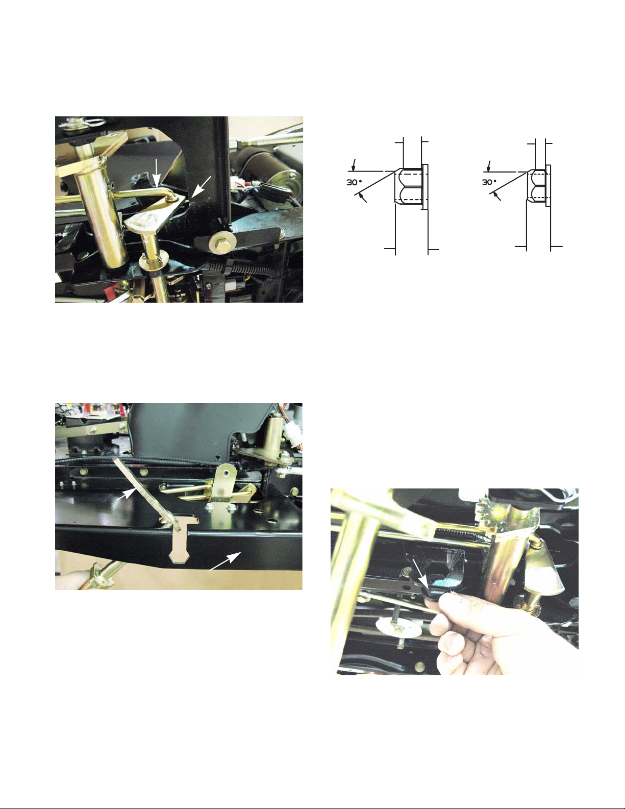
DRIVE SYSTEM-IVT
´
´
´
´
1(:
02',),('
15. Install the right side brake link onto the brake
pedal shaft using a new cotter pin.
See Figure 5B.61
Brake link
Cotter
pin
Figure 5B.61
16. Install the reverse drive pedal shaft.
16a. Rotate the reverse drive pedal shaft into
the reverse pedal support.
See Figure 5B.45
16c. Modify the hex bushing by:
• Cut or grind the bushing to an overall height
of 1/2” . See Figure 5B.63
Figure 5B.63
• Grind a 30
o
tapper on the hex end of the
bushing.
NOTE: The hex part of the bushing must be at
least 0.2” in height.
reverse drive
pedal shaft
Reverse pedal support
Figure 5B.62
16b. Install the split hex bushing.
NOTE: The split must face up while the bushing
is installed.
NOTE: Using a modified bushing will allow the
bushings on the reverse drive pedal shaft to be
serviced in the future without taking the fenders
off of the tractor.
16d. Install the modified hex bushing.
See Figure 5B.64
Modified hex bushing
Figure 5B.64
47
Page 54

DRIVE SYSTEM-IVT
16e. Slide the reverse drive pedal shaft into the
modified hex bushing while aligning the
timing marks on the gears of the two
shafts. See Figure 5B.65.
• One mark on the fourth tooth from the bottom of
the reverse gear.
• One mark on the fourth valley from the valley of
the main drive shaft gear.
Timing marks
17. Install the fender by following the steps
described in Chapter 4: Body/Chassis.
18. Test drive the tractor before returning it to service.
19. Install the deck as described in chapter 8 Cutting
Decks and Lift Shaft.
Figure 5B.65
16f. Install the washer and hair pin clip.
See Figure 5B.66
Hair pin clip
Figure 5B.66
48
Page 55

STEERING-HYDROGEAR
CHAPTER 6A: STEERING - HYDROGEAR TRANSMISSIONS
Introduction
The steering on the I-series tractor works in two
phases.
• First it will steer like any other tractor by turning
the front wheels.
• Second and more importantly, the steering linkage will control the drive output of the rear
wheels through the use of two HydroGear transmissions.
The steering gear box is connected to the front
wheels by drag links. When the steering wheel is
turned, the gear box will turn the wheels. The gear box
will slow the drive speed of the inside rear wheel. At
approximately 50
o
the steering gear box will start to
slow down the outside drive wheel. When the inside
front wheel reaches an angle of 90
o
, the rear wheel on
that side will stop driving. Turning the wheel past that
point will make the inside rear wheel go in reverse The
inside front wheel can reach a 108
o
angle and with the
transmission on the inside of the turn driving in reverse.
The tractor will then be in a zero turn.
Because the steering gear box is linked to the
transmissions, the transmission adjustments and the
wheel alignment must be addressed together. A transmission that is out of adjustment can make the steering
look out of adjustment just as a steering linkage that is
out of adjustment will affect the transmissions.
IMPORTANT: Check the tire air pressure before
attempting to diagnose any problems with the
steering or tracking of an I-series tractor. If the
tire air pressures are not equal across the same
axles, it will greatly affect the performance of the
tractor.
Cam Slot Angle Adjustment
The cam slot adjustment is a critical adjustment on
the I-series tractor, but it should only be necessary in
two cases.
1. The cam slot angle adjustment must be set if the
steering gear box is replaced.
2. In the extremely rare case that the angle is sim-
ply out of adjustment. The indications are as follows:
NOTE: Test tractor in a safe area in case the
tractor moves during testing.
A The tractor is running.
B Parking brake released.
C Feet off of the brake and drive pedals.
D Turn the steering wheel fully in both direc-
tions.
E If the tractor creeps, cam angle needs
adjusted. If the tractor does not creep, cam
slot angle adjustment is not needed. Proceed to the neutral and alignment adjustments.
The second would be a safety issue
! CA UTION! CA UTION
and must be addressed before
returning the tractor to service
To adjust the cam slot angle:
NOTE: A special tool P/N 753-05437 is needed
to make this adjustment. Do not attempt to make
this tool, if needed it can be ordered from the
Cub Cadet parts department.
1. Remove the dash and fender by following the
steps described in Chapter 4: Body/Chassis.
49
Page 56

STEERING-HYDROGEAR
2. Disconnect the transmission link from the right
side of the gear box only.
2a. Removing the nut and bolt that passes
through the double roller. See Figure 6A.1.
Remove this nut
and bolt
Cam slot
Figure 6A.1
2b. Remove the cotter pin and clevis pin.
See Figure 6A.2.
2c. Raise the transmission link away from the
cam slot.
NOTE: Catch the double roller when lifting the
transmission link away from the steering gear
box. See Figure 6A.3.
Double roller
Figure 6A.3
3. Loosen the return to neutral bolt using a 9/16”
wrench and a 1/4” hex key. See Figure 6A.4.
Cotter pin
Clevis pin
Figure 6A.2
Return to neutral bolt
Figure 6A.4
50
Page 57
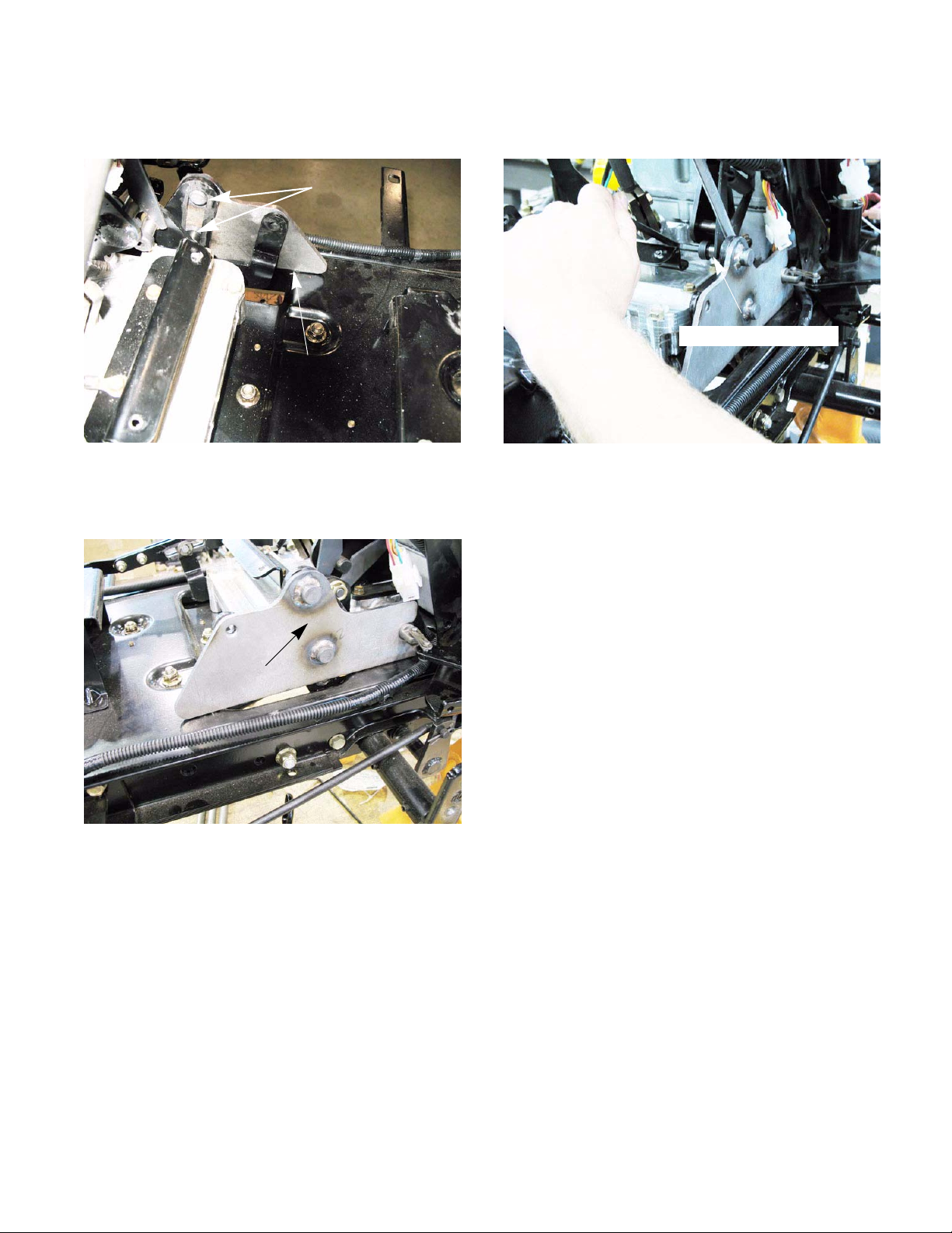
STEERING-HYDROGEAR
4. Insert the pins of the gauge block tool P/N 75305437 into the cam slot. See Figure 6A.5.
Pins
Gauge block tool
Figure 6A.5
5. Rest the tool flat against the frame.
See Figure 6A.6.
6. Tighten the return to neutral bolt.
See Figure 6A.7.
Return to neutral bolt
Figure 6A.7
7. Remove the gauge block.
8. Adjust the transmission for neutral and align the
front wheels as described in the following sections of this chapter.
P/N 753-05437
Figure 6A.6
9. Reassemble the tractor.
10. Test drive the tractor in a safe area before
returning it to service.
51
Page 58

STEERING-HYDROGEAR
Neutral and Transmission Links Adjustment
The first step is to coordinate the neutral points of
the steering gear box, both transmissions and the control linkages. The transmission links will self adjust
when the neutral adjustment and wheel alignment are
done. To establish neutral:
1. Lock Steering Gear Box in Neutral Position:
1a. Remove the 1/4”-20 plug screw from the
steering gear box centering port using a 3/8”
wrench. See Figure 6A.8.
Remove this screw
1d. Finger tighten the screw to set the screw
fully into the detent. The steering gear box is
now centered and locked. See Figure 6A.9.
2” bolt
Figure 6A.9
2. Jack the tractor up so that both rear wheels are
off of the ground. Place a pair of jack stands
under the rear transmissions.
See Figure 6A.10.
Figure 6A.8
1b. Thread a 1/4”-20x2” bolt into the steering
box centering port until you feel it touch the
steering rack.
1c. While trying to gently thread the bolt further,
slowly rotate the steering shaft back and
forth until the bolt seats into the detent in the
steering rack.
Place jack stands here
Figure 6A.10
52
Page 59

STEERING-HYDROGEAR
3. Loosen the two screws that connect each drive
control link to the shifter T-plate on each transmission. See Figure 6A.11.
Loosen these screws
Figure 6A.11
NOTE: Feel the shifter T-plate, it should be free
of any input from the transmission links. If tension is felt there, disconnect the links completely .
4. While sitting in the seat, start the tractor and run
it at full throttle. Release the brake.
The tractor engine and drive system
! CA UTION! CA UTION
Confirm that no hazards will be incurred by running the
engine or operating the drive system
5. Check the rear wheels.
NOTE: The rear wheels should not turn. If either
wheel turns, adjust the transmission for neutral
by:
must be operated to complete this
procedure.
Shifter T-plate
5a. Loosen the socket head cap screw in the
slot of the shift selector plate.
See Figure 6A.12.
Loosen this bolt
Shift selector plate
Figure 6A.12
NOTE: It is not necessary to remove the fender
for this step. The fender was removed in this
photo for clarity.
NOTE: Only loosen the screws on the side that
creeps.
5b. With the tractor still running, move the shift
selector plate until the wheel stops moving.
NOTE: For the best zero-turn performa n ce , Set
the selector plate to the reverse side of the neutral band (region where the transmission is in
neutral).
5c. Tighten the socket head cap screw.
NOTE: Leave the transmission links loose until
the wheels are aligned.
6. Perform the wheel alignment by following the
procedures described in the next section of this
manual.
53
Page 60

STEERING-HYDROGEAR
Wheel alignment
NOTE: The transmission neutral adjustment
must be done prior to adjusting the steering linkage.
1. Remove the three screws holding each steering
gear cover in place. See Figure 6A.13.
Remove
these screws
Figure 6A.13
3. Insert a 5/16” pin through the hole in the steering gear on each side. The pins should pass
through the gears, through the lower cover plate
and into the pivot bar. See Figure 6A.15.
5/16” punch
Figure 6A.15
NOTE: If the alignment is off, the holes may not
line up. If this is the case, adjust the front end by:
2. Rotate the front tires until the marks on the axle
gears and the steering gears align.
See Figure 6A.14.
Insert a 5/16” pin
here
Align the timing marks
Steering gear
Axle gear
Figure 6A.14
3a. Loosen the jam nuts on both ends of the
drag link. See Figure 6A.16.
Loosen both jam nuts
Figure 6A.16
54
Page 61

STEERING-HYDROGEAR
3b. Adjust the drag link until the holes line up
See Figure 6A.17.
Rotate to lengthen or shorten
Figure 6A.17
NOTE: The punch should slide in and out with-
out binding. As the drag links are being adjusted,
rock the tires back and forth to remove the load
created from the tires twisting on the floor.
Steering gear box removal
To replace the gear box:
1. Remove the dash and fender by following the
steps described in Chapter 4: Body/Chassis.
2. Disconnect the transmission linkages:
2a. Remove the cotter pins, washers and clevis
pins in the linkages. See Figure 3.18.
Hair pin clip
Clevis pin
3c. Tighten the jam nuts.
4. Tighten the drive control links to the T-plates.
5. Remove the 1/4”-20x2” screw from the steering
gear box.
6. Reinstall the original plug screw in the steering
gear box.
7. Install the steering gear covers.
Never allow an I-series tractor to be
! CA UTION! CA UTION
8. Test drive the tractor in a safe area before
returning it to service.
operated with out the steering gear
covers. Personal injury may result.
Figure 3.18
2b. Remove the nuts and bolts conn ecting the
transmission linkages to the levers on the
steering gear box. See Figure 6A.19.
Roller
Cam slot
Connector link
Figure 6A.19
2c. Lift the links away from the gear box.
NOTE: There are rollers in the slots. Take care
not to lose them when removing the bolts.
55
Page 62

STEERING-HYDROGEAR
3. At the bottom of the lever with the cam slot there
is a connector link. Remove the hairpin clip and
push it out of the lever. See Figur e 6A.20.
Remove hair pin
clip
Figure 6A.20
4. Disconnect the steering links on both sides:
4a. Gently pry the link retainer over the master
link. See Figure 6A.21.
5. Remove the transmission dampener cylinder
using two 1/2” wrenches. See Figure 6A.22.
Transmission dampener
Figure 6A.22
6. Remove the steering shaft by removing the two
clamp bolts in the steering shaft receiver and lifting the shaft out. See Figure 6A.23.
Steering shaft
Steering link
Figure 6A.21
Retainer
Steering shaft
Receiver
Figure 6A.23
56
Page 63

NOTE: Rotating the steering shaft bushing 90
degrees will allow the bushing to pop out, relieving the pressure on the steering shaft. This will
make it easier to remove or install the shaft.
See Figure 6A.24.
STEERING-HYDROGEAR
8. Remove the four screws holding the g ear bo x to
the frame with a 1/2” wrench. See Figure 6A.26.
Rotate the bushing 90
o
Figure 6A.24
7. Disconnect the ground wire. See Figure 6A.25.
Ground wire
Figure 6A.26
9. The new gear box should come with 1/4”-20 x 2”
screw to lock it into the neutral/centered position.
10. Bolt the gear box to the frame with the four bolts
removed in step 8.
11. Insert the steering shaft into the steering shaft
receiver. Tighten the nuts to a torque of 130 160 in lbs (14.7 - 18.0 Nm).
12. Attach the steering links. Install the retainers.
13. Attach the transmission dampener to the gear
box.
14. Place the link into the bottom of the lever with
the cam slot. Insert the hairpin clip to hold it in
place. See Figure 6A.27.
Figure 6A.25
Link connecting the
drive pedal to the
cam slot
Figure 6A.27
57
Page 64

STEERING-HYDROGEAR
15. Apply anti-seize compound to the rollers and the
cam slots on the gear box levers.
See Figure 6A.28.
Apply never seize
Figure 6A.28
16. Adjust the speed cam angle by following the
steps described in the previous section.
17. Connect the transmission links.
18. Insert the clevis pins, washers and cotter pins.
19. Align the wheels and adjust the transmission
links by following the steps described at the
beginning of this chapter.
20. Remove the 1/4”-20x2” bolt that came with the
steering gearbox, and install the short one from
the old gearbox.
21. Install the fender and dash by following the steps
described in Chapter 4: Body/Chassis.
22. Test drive the tractor in a safe area before
returning to service.
17a. Place the rollers into the cam slots and
slide the transmission links over the levers.
17b. Insert the bolt through the transmission link
and roller .
17c. Install the nut on the bolt and tighten to a
torque of 8 ft lbs (11 Nm).
See Figure 6A.29.
Roller
58
Figure 6A.29
Page 65
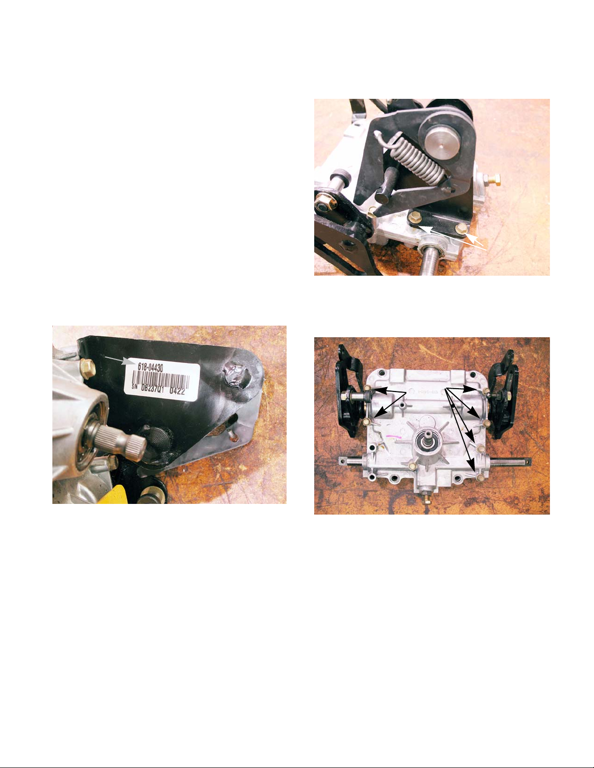
STEERING-HYDROGEAR
Rebuilding the steering gear box
There are two different gear boxes available for the
I-series tractors that are equipped with HydroGear
transmissions.
• The 618-04430 steering gear box was used until
the end of the 2007 model year.
• The 618-04634 steering gear box was used in
2008 through current production.
The procedures to rebuild both gear boxes are similar. Wh ere there are di ffe rences, they will be called ou t
in the text.
To take the steering gear box apart:
1. Remove the steering gear box by following the
procedures described in the previous section of
this chapter.
2. Identify the gearbox assembly using the serial
number tag located on the return to neutral
bracket. See Figure 6A.30.
Model number
3. Remove the return to neutral bracket using a
3/8” wrench. See Figure 6A.31.
Remove these
screws
Figure 6A.31
4. Remove the six remaining case screws using a
3/8” wrench. See Figure 6A.32.
Figure 6A.30
Remove
these
screws
Figure 6A.32
59
Page 66

STEERING-HYDROGEAR
5. Lift the upper housing off of the lower housing.
NOTE: There is no sealant between the two
housings. They should easily slip apart. If they
are stuck together, there are three pry points
cast into the housings that can be used to separate the housings. See Figure 6A.33.
Using one of the pry
points to separate the
housings.
Figure 6A.33
7. Remove the speed cam assemblies.
See Figure 6A.35.
Speed cam assemblies
Figure 6A.35
8. Separate the speed cam assemblies.
See Figure 6A.36.
6. Remove the steering rack. See Figure 6A.34.
Steering
rack
Figure 6A.34
Figure 6A.36
60
Page 67

STEERING-HYDROGEAR
9. Separate the speed cam from the output bevel
gear assembly by removing the small snap ring
from the speed cam shaft. See Figure 6A.37.
Speed cam
Output bevel gear assembly
Small snap ring
Figure 6A.37
10. Separate the output bevel gear assembly by
removing the snap ring. See Figure 6A.38.
11. Remove the washer from the input sector gear.
See Figure 6A.39.
NOTE: The 618-04430 gear boxes only
Remove the washer
Input sector
gear
Figure 6A.39
12. Remove the input sector gear.
See Figure 6A.40.
Remove this snap ring
Figure 6A.38
Figure 6A.40
61
Page 68

STEERING-HYDROGEAR
13. Inspect the input sector gear bushings for damage and/or signs of wear. If they show signs of
wear of damage, press both of the bushings out
of the input sector gear using a press.
See Figure 6A.41.
Press out the
bushings
Figure 6A.41
14. Remove the internal cam, the washer under it
and the steering shaft. See Figure 6A.42.
15. Remove both of the bevel gears.
See Figure 6A.43.
Bevel gears
Figure 6A.43
16. Remove the spiral ring from the post on the
bevel gear. Slide the roller off of the bevel gear.
See Figure 6A.44.
Washer
Internal cam
Figure 6A.42
Steering
shaft
Post
Roller
Spira l ring
Figure 6A.44
62
Page 69

STEERING-HYDROGEAR
17. Remove the snap ring from the input shaft.
See Figure 6A.45.
Figure 6A.45
18. Remove the input shaft from the inside of the
housing. See Figure 6A.46.
19. Remove the wear block.
NOTE: On early production models of the 618-
04430 and all versions of the 618-04634 steering gear boxes there is a spring that presses the
wear block against the steering rack.
See Figure 6A.47.
Wear block
Figure 6A.47
Input shaft
Figure 6A.46
NOTE: On late production models of the 618-
04430 steering gear boxes there is a bolt that
applies pressure to the wear block. When
removing the wear block; make sure to get the
washer out of it. See Figure 6A.48.
Adjustment bolt
Washer
Figure 6A.48
NOTE: Unless the upper housing or wear block
is being replaced, leave the adjustment bolt in
place.
Wear block
63
Page 70

STEERING-HYDROGEAR
20. Inspect the bearings. If they are worn or rough,
carefully drive the inner bearing out of the upper
housing using a pin punch and ha mmer.
See Figure 6A.49.
Drive out the inner bearing
Figure 6A.49
21. Drive the outer bearing out of the upper housing
using a pin or brass punch and hammer.
See Figure 6A.50.
To assemble the steering gear box:
1. Put a dab of 737-0300A Durina
TM
grease into
each of the bushings in the lower housing.
See Figure 6A.51.
Put a dab of grease in each bushing
Figure 6A.51
2. Install both of the bevel gears with the rollers line
with the center of the housing.
See Figure 6A.52.
Figure 6A.50
22. T horoughly clean and degrease all parts.
23. Inspect all parts for signs of wear or damage.
NOTE: If the part has signs of wear or damage;
discard the part.
NOTE: If the two bushings in the bottom of lower
gear box housing are worn, replace the lower
housing and press in two new bushings.
64
Rollers in line with the
center of housing
Figure 6A.52
Page 71

STEERING-HYDROGEAR
3. Insert the steering shaft. See Figure 6A.53.
Steering shaft
Figure 6A.53
4. Place the large washer over the steering shaft.
See Figure 6A.54.
5. Install the internal cam with the shoulder facing
up. The bevel gear rollers in the slots.
See Figure 6A.55.
Slots
Shoulder
Figure 6A.55
6. Apply a dab of 737-0300A Durina
TM
grease to
the side of the steering shaft. See Figure 6A.56.
Large washer
Figure 6A.54
Figure 6A.56
65
Page 72

STEERING-HYDROGEAR
7. Insert the input sector gear into the internal cam.
NOTE: The input sector gear and the internal
cam have a master spline to time the two to
each other. See Figure 6A.57.
Master
spline
Figure 6A.57
8. On the 618-04430 gear boxes, place the smaller
washer over the steering shaft.
See Figure 6A.58.
Speed cam
Shim
Bushing
Hydro arm
Figure 6A.59
9c. Place a .030” shim over the hydro arm.
See Figure 6A.59.
NOTE: The bevel gear needs to be shimmed to
a bind. That means that once the assembly is
installed in the lower housing, there is zero play
between the bushing and the bevel gear. It may
take a few attempts to get the shims correct.
9d. Place the output bevel gear on the hydro
arm with the chamfer facing away from the
hydro arm. See Figure 6A.59.
Output bevel gear
Chamfer
Smaller washer
Figure 6A.58
9. Assemble the output bevel gear assemblies.
9a. Insert the shaft of the left speed cam into the
left hydro arm. See Figure 6A.59.
9b. Place a bushing over the hydro arm with the
flange facing away from the arm.
See Figure 6A.59.
NOTE: If the output bevel gears are put on backwards it will throw off the timing of the gearbox.
NOTE: The hydro arms and output bevel gears
have master splines to time them to each other.
See Figure 6A.60.
Master spline
Figure 6A.60
66
Page 73
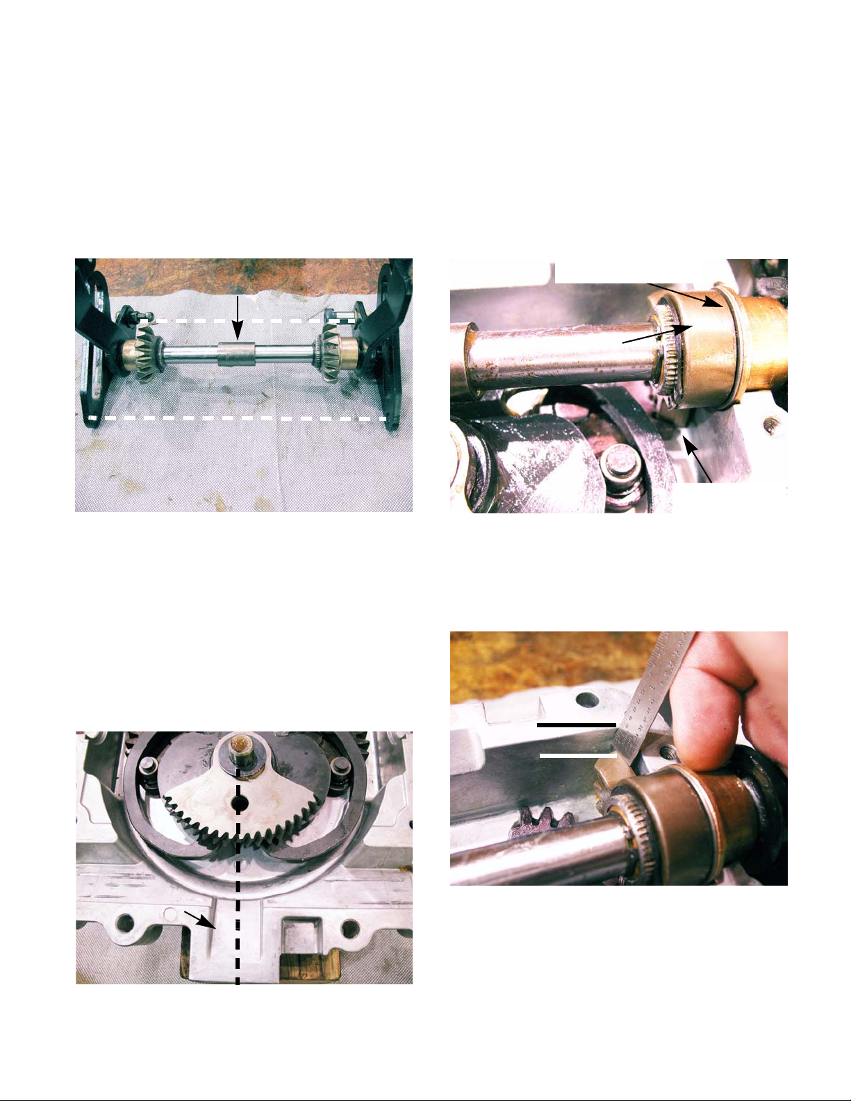
STEERING-HYDROGEAR
9e. Install both of the snap rings.
9f. Repeat for the right output bevel gear
assembly.
10. Place both output bevel gear assemblies on the
bench, facing each other. With both assemblies
resting on the same points of the speed cam,
insert both shafts into the coupler.
See Figure 6A.61.
Coupler
Both speed cam are in line
Figure 6A.61
• The bevel gears should face away from the input
sector gear.
• The first tooth of each output bevel gear should
rest in the first valley the bevel gears in the bottom of the lower housing.
• The output bevel gear should have no play once
it is installed. If it does have play go back to step
9. See Figure 6A.63.
Shimmed to a bind
Output bevel gear
Proper gear
timing
Figure 6A.63
NOTE: The coupler has a master spline, but the
speed cam shafts do not. If both speed cams are
not resting on the same points when coupled
they are out of time.
11. Insert the speed cam assemblies in the lower
housing.
• Align the hole in the input sector gear with the
the center of the square recess at the front of the
lower housing. See Figure 6A.62.
Recess
NOTE: To test proper gear timing; measure from
the farthest point of the output bevel gear to the
top of the housing. It should measure a 1/4” for
both sides. See Figure 6A.64.
1/4”
Figure 6A.64
NOTE: If one or both of the output bevel gears
are out of time; the steering rack will lose travel
on the affected side.
Figure 6A.62
67
Page 74

STEERING-HYDROGEAR
12. Fill the lower housing with 12 oz. of 737-0300A
TM
Durina
grease. See Figure 6A.65.
Figure 6A.65
13. Press in the upper ball bearing into the upper
housing. See Figure 6A.66.
Press in the upper
ball bearing
14. Press the lower ball bearing into the upper housing. See Figure 6A.67.
A socket can
be used to press
in the ball bearing
Figure 6A.67
15. Insert the input shaft thought the ball bearings
from the inside of the steering gear box.
See Figure 6A.68.
Figure 6A.66
Inset the
input shaft
Figure 6A.68
68
Page 75

STEERING-HYDROGEAR
16. Install the snap ring on the input shaft.
See Figure 6A.69.
Snap ring
Figure 6A.69
17. Install the wear block:
• For the 618-04430 steering gear boxes with the
adjustment bolt:
• For all other steering gear boxes:
17c. Insert the spring into the wear block.
17d. Set the wear block and spring into the
square recess in the upper housing.
See Figure 6A.71.
Wear block
Figure 6A.71
17a. Insert the washer into the hole in the wear
block.
17b. Slide the wear block and washer onto the
adjustment bolt. See Figure 6A.70.
wear block
Figure 6A.70
18. Slide one new bushing onto each side of the
steering rack, with the flanges facing the center
of the rack.
19. Set the steering rack into the grove in the upper
housing; trapping it between the input shaft and
the wear block. See Figure 6A.72.
NOTE: The hole in the steering rack should line
up with the hole in the housing.
See Figure 6A.72 Insert.
Align
holes
Figure 6A.72
69
Page 76

STEERING-HYDROGEAR
20. With the wear block facing the front, adjust the
steering rack until the right side measures 1.8”
from the case to the shoulder at the end of the
shaft. See Figure 6A.73.
1.8”
Figure 6A.73
21. Holding the steering rack in place, carefully set
the upper case onto the lower case.
NOTE: Removal of the return to neutral bolt and
the dampener post from the speed cam assemblies will make it a lot easier to put the upper
case half onto the lower case half.
NOTE: If removing the dampener post, mark its
location on the speed cam assembly to ensure
proper reassembly.
NOTE: The upper case should drop into place.
Do not force it.
22. Check the timing of the gear box:
22a. Turn the input shaft until the steering rack
has moved all the way to the left. The right
shoulder should be flush with the housing.
See Figure 6A.74.
Shoulder be flush
with the housing
Figure 6A.74
22b. Turn the input shaft until the steering rack
has moved all the way to the right. The left
shoulder should be flush with the housing.
23. Install the return to neutral bracket.
24. Install the remaining housing screws.
25. If the dampener post was removed, re-install it.
26. If the return to neutral bolt was removed, reinstall it.
NOTE: The return to neutral bolt does not need
to be tightened at this time. It will be adjusted
and tightened when it is installed in the tractor.
70
NOTE: On 618-04430 gear boxes with the
adjustment bolt, perform the wear block adjustment by following the steps described in the
wear bolt adjustment section of this chapter.
27. Thread a 1/4”-20x2” bolt into the hole in the gear
box to lock the gear box in neutral.
28. Install the steering gear box in the tractor and
perform the neutral adjustments, speed cam
adjustments and the wheel alignment by following the procedures described in this chapter.
29. Test drive the tractor in a safe area before
returning to service.
Page 77

STEERING-HYDROGEAR
Wear block adjustment
All of the steering gear boxes have a wear block
that presses the wear block against the steering rack to
set the back lash between the steering rack and the
input shaft. Most of the steering gear boxes have a
spring that holds a constant pressure on the wear
block.
On some of the 618-04430 steering gear boxes,
there is an adjustment bolt for the wear block. To adjust
the bolt:
NOTE: This procedure can be performed while
the steering gear box is installed in the tractor.
1. If the steering gear box is installed in the tractor,
isolate it by disconnecting both of the steering
links. See Figure 6A.75.
Retainer
Steering link
3. While turning the input shaft, tighten the adjustment bolt until increased drag is felt.
See Figure 6A.77.
Rotate
input
shaft
Tighten bolt until drag increases
Figure 6A.77
4. Back the bolt off a quarter to a half turn.
5. While holding the adjustment bolt with one
wrench, tighten the jam nut to lock it in place.
Figure 6A.75
2. Loosen the jam nut on the adjustment bolt using
a 9/16” wrench. See Figure 6A.76.
6. Check the steering gearbox by turning it through
its full range of motion. Drag should be consistent through the complete range.
7. Install the gear box in the tractor or attach the
steering links if it was already installed.
8. Test drive the tractor in a safe area before
returning to service.
Loosen the
jam nut
Figure 6A.76
71
Page 78

STEERING-HYDROGEAR
Front wheels and axles
Remove/ replace the front wheels:
1. Lift and safely support the front end of the tractor.
2. Gently pry off the hub cap. See Figure 6A.78.
Hub cap
Figure 6A.78
To replace the front wheel ball bearings:
1. Lift and safely support the front end of the tractor.
2. Remove the front wheel by following the procedures describe in the previous section of this
chapter.
3. Drive the bearings out of the wheel hub using a
drift or pin punch. See Figure 6A.80.
Ball bearing
3. Remove and discard the cotter pin.
See Figure 6A.79.
Cotter pin
Washer
Figure 6A.79
4. Remove the washer. See Figure 6A.79.
5. Slide the wheel off of the axle.
Figure 6A.80
4. Drive in the new bearings using a brass punch.
See Figure 6A.81.
Figure 6A.81
5. Install the front wheel.
6. Pump grease in the grease fitting on the front
wheel until it starts to squirt out of the hub.
7. Test drive the tractor before returning it to service.
72
Page 79

STEERING-HYDROGEAR
To remove/ replace the front axles:
1. Lift and safely support the front of the tractor.
2. Remove the front wheel by following the procedures the front wheel section of this chapter.
3. Remove the steering gear covers.
4. Insert a 5/16” pin punch into one of the alignment holes to lock the steering gears in place.
See Figure 6A.82.
Pin punch
Steering gear
7. Take the bolt all the way out.
NOTE: The axle should fall out at this point.
8. Install the axle by following the previous steps in
reverse order.
NOTE: Align the timing marks when installing
the outboard steering gear. See Figure 6A.84.
Timing marks
Figure 6A.84
Figure 6A.82
5. Loosen the bolt that holds the outboard steering
gear to the axle. Back the bolt half way out.
NOTE: The axle had a tapered double-D shaft.
The steering gear will be very tight on the shaft.
6. Strike the bolt head, using a brass punch and a
hammer. This will loosen the axle from the outboard steering gear. See Figure 6A.83.
Brass punch
9. Test drive the tractor in a safe area before
returning it to service.
Figure 6A.83
73
Page 80

STEERING-HYDROGEAR
Drag links
To remove/replace a drag link:
1. Remove the steering gear covers.
2. Remove and discard the nut holding th e dr ag
link to the inboard steering gear using two 9/16”
wrenches (one of them should be a slim-line
wrench). See Figure 6A.85.
Drag link
5. Remove the spherical rod ends.
NOTE: Count the number of turns to remove the
spherical rod ends.
6. Install new spherical rod ends.
NOTE: Install the spherical rod ends the same
number of turn as it took to remove them from
the old drag link.
NOTE: Leave the jam nuts loose.
7. Install the drag link on the tractor.
8. Perform a wheel alignment by following the procedures described in the wheel alignment section of this chapter.
9. Test drive the tractor in a safe area before
returning it to service.
Figure 6A.85
The nuts used on the drag links and
! CAUTION! CAUTION
thread locking compound. Use new nuts every time.
3. Remove the nut and bolt that secures the drag
link to the steering arm. See Figure 6A.86.
Steering arm
the tie rod are single use only. Do
not try to reuse them by applying a
Drag link
Figure 6A.86
4. Loosen the jam nuts.
74
Tie rod
Page 81

STEERING-HYDROGEAR
To remove/replace the tie rod:
1. Remove the steering gear covers.
2. Remove and discard the nut holding the tie rod
spherical rod ends to the inboard steering gear
using two 9/16” wrenches (one of them should
be a slim-line wrench). See Figure 6A.87.
tie rod
spherical rod
end
Figure 6A.87
To remove/replace the inboard steering gear or king
pin:
1. Remove the steering gear covers.
2. Remove and discard the nut holding the tie rod
spherical rod ends to the inboard steering gear
using two 9/16” wrenches (one of them should
be a slim-line wrench). See Figure 6A.88.
3. Remove and discard the nut holding the dr a g
link to the inboard steering gear using two 9/16”
wrenches (one of them should be a slim-line
wrench). See Figure 6A.88.
Tie rod end
Bolt
Drag link
end
Timing marks
The nuts used on the drag links and
! CAUTION! CAUTION
thread locking compound. Use new nuts every time.
3. Repeat on the other side of the tractor.
4. Slide the tie rod out of the tractor.
5. Loosen the jam nuts.
6. Remove the spherical rod ends.
NOTE: Count the number of turns to remove the
spherical rod ends.
7. Install new spherical rod ends.
NOTE: Install the spherical rod ends the same
number of turns as it took to remove them from
the old tie rod.
8. Install the tie rod on the tractor using new lock
nuts.
9. Perform a wheel alignment by following the procedures described in the wheel alignment section of this chapter.
the tie rod are single use only. Do
not try to reuse them by applying a
Figure 6A.88
4. Remove the inboard steering gear by removing
the bolt using a 9/16” wrench.
5. Remove the cotter pin in the bottom of the king
pins. See Figure 6A.89.
6. Push the king pins out of the pivot bar.
King pin
Cotter
pin
10. Test drive the tractor in a safe area before
returning it to service.
Inboard steering gear
Figure 6A.89
75
Page 82
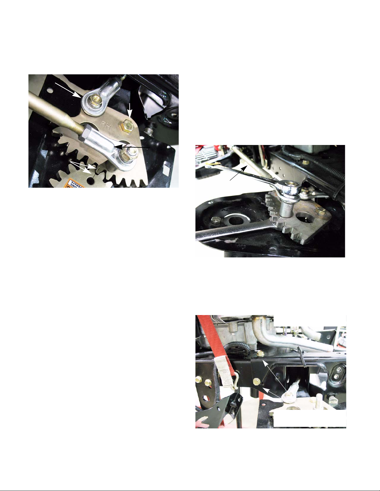
STEERING-HYDROGEAR
B
7. Install the king pin.
8. Align the timing marks and install the inboard
steering gear.
Tie rod end
Bolt
Drag link
end
Timing marks
Figure 6A.90
9. Attach the tie and drag link ends using new lock
nuts.
Pivot bar
To remove/replace the pivot bar:
1. Lift and safely support the front end of the tractor.
2. Remove the front axles by following the procedures described in the front wheels and axles
section of this chapter.
3. Remove and discard the nut holding the dr a g
link to the inboard steering gear using two 9/16”
wrenches (one of them should be a slim-line
wrench). See Figure 6A.91.
Drag link
10. Perform a wheel alignment by following the procedures described in the wheel alignment section of this chapter.
11. Test drive the tractor in a safe area before
returning it to service.
Figure 6A.91
4. Remove the muffler by following the steps
described in Chapter 2: Engine Related Parts.
5. Remove the four screws fastening the bumper
mount bracket to the frame. See Figure 6A.92.
Bumper mounting bracket
76
Remove these screws on
each side
Figure 6A.92
Page 83

STEERING-HYDROGEAR
6. Remove the pivot bar shoulder bolts.
See Figure 6A.93.
Shoulder bolts
Pivot bar bracket
Figure 6A.93
At this point there is nothing hold-
! WA RNING! WA RNING
ing the pivot bar in place. Take care
to prevent the pivot bar from falling
off of the tractor.
7. Slide the bumper mounting bracket and the pivot
bar bracket off of the tractor.
8. Remove the pivot bar.
9. Inspect the contact areas where the pivot bar
meets the frame. If there is any material that h as
erupted or any galling, sand it down. Repeat
inspection on the inside of the pivot bar bracket.
See Figure 6A.94.
10. With the pivot bar on a bench, the inboard steering gear and the tie rod can be serviced.
11. Remove the tie rod by removing and discarding
the nut holding the tie rod ends to the in board
steering gear. See Figure 6A.95.
Remove nuts
Figure 6A.95
12. Remove the inboard steering gear by removing
the bolt using a 9/16” wrench.
13. Remove the steering king pins by:
13a. Removing the cotter pins in the bottom of
the king pins.
13b. Push the king pins out of the pivot bar.
See Figure 6A.96.
Inspect contact area
Figure 6A.94
Cotter pin
King pin
Figure 6A.96
77
Page 84

STEERING-HYDROGEAR
14. Start re-assembling the pivot bar by inserting the
steering king pins into the pivot bar . Secu re them
with new cotter pins. See Figure 6A.97.
King pin
Cotter pin
Figure 6A.97
15. Install the axle assemblies.
16. Place the outboard steering gears on the axle s
and tighten to a torque of 100 - 150 in-lbs (11 17 Nm).
NOTE: The steering gears are marked LH and
RH. Make sure the LH is facing up on the left
hand side and that the RH is facing up on the
right.
18. Insert a 5/16” pin punch in the alignment holes of
the out board steering gears.
NOTE: Make sure they go all the way through
into the pivot bar to lock the gears in position.
See Figure 6A.98.
5/16” pin punch
Timing marks
Adjust tie rod end
jam nut
Figure 6A.98
19. Adjust the tie rod ends by loosening the jam nuts
and rotating the tie rod ends until they slide on to
the 1/4” bolts sticking up through the inboard
steering gears. Tighten the jam nuts to lock the
tie rod ends in place. See Figure 6A.98.
20. Install the tie rod end using a new lock nut.
17. Apply a small amount of releasable thread locking compound such as Loctite® 242 (blue) to the
bolt for the in board steering gears. Align the timing marks on the inboard and outboard steering
gears and tighten the bolt that fastens the
inboard steering gears to a torque of 380 - 450
in- lbs (43 - 51 Nm).
NOTE: Make sure the bolts for the drag link and
tie rod are in the in place before installing the
steering gears.
21. Apply high quality grease to the frame and the
inside of the pivot bar bracket, where the pivot
bar rides. See Figure 6A.99.
Apply grease here
Figure 6A.99
78
Page 85

22. Install the pivot bar by following steps 3 - 7 in
reverse order.
NOTE: When installing the pivot bar, use a
clamp to line up the screw holes in the frame,
pivot bar and bumper mounting brackets.
See Figure 6A.100.
STEERING-HYDROGEAR
Figure 6A.100
23. Slide the front wheels on and secure them with
new cotter pins.
NOTE: Make sure the washer is installed
between the wheel bearings and the cotter pin.
24. Push the hub caps on till they snap in place.
25. Take the tractor off of the jack stands.
26. Perform a neutral adjustment and wheel alignment as described in the beginning of this chapter.
27. Test drive the tractor in a safe area before
returning to service.
79
Page 86

STEERING-HYDROGEAR
80
Page 87
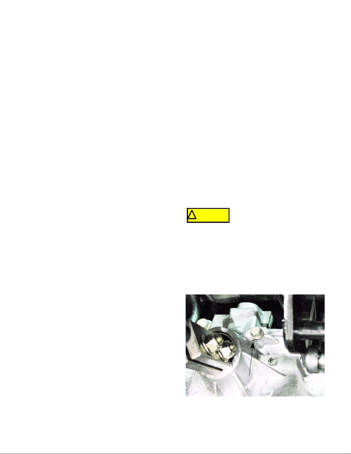
CHAPTER 6B: STEERING - IVT T RANSMISSION
STEERING-IVT
Introduction
Just like the I-series with HydroGear transmissions, the steering on the I-series tractor with the
Infinitely Variable Transmission (IVT) works in two
phases. First it will steer like any other tractor by turning the front wheels. Second and more importantly, the
steering linkage will control the drive output of the rear
wheels through the use of the IVT transmission.
The steering gear box is attached to the front
wheels by drag links. When the steering wheel is
turned, the gear box will turn the wheels. When the
wheels reaches around a 55
o
angle from straight
ahead, the gear box will start to slow the transmission
on the inside of the turn and continue turning the front
wheels. When the inside wheel reaches an angle of
o
90
, the rear wheel on that side will stop driving. Turning the wheel past that point will make the inside rear
wheel go in reverse The inside front whee l can reach a
o
108
angle. With the inside front wheel at a 108o angle
and the transmission on the inside of the turn going in
reverse, the tractor will be in a zero turn.
Because the steering gear box is linked to the
transmission, the transmission adjustments and the
wheel alignment must be addressed together. A transmission that is out of adjustment can make the steering
look out of adjustment just as a front end that is out of
adjustment will affect the adjustment of the transmission.
IMPORTANT: Check the tire air pressure before
attempting to diagnose any problems with the
steering or tracking of an I-series tractor. If the
tire air pressures are not equal across the same
axles, it will greatly affect the performance of the
tractor.
Cam Slot Angle Adjustment
The cam slot adjustment is a critical adjustment on
the I-series tractor. It should only be necessary when
replacing the steering gear box.
1. The cam slot angle adjustment must be set if the
steering gear box is replaced.
2. In the extremely rare case that the angle is sim-
ply out of adjustment. The indications are as follows:
A The tractor is running.
B Parking brake released.
C Feet off of the brake and drive pedals.
D Turn the steering wheel fully in both direc-
tions.
E If it creeps, cam angle needs adjusted.
The second would be a safety issue
! CA UTION! CA UTION
and must be addressed before
returning the tractor to service
To adjust the cam slot angle:
1. Remove the dash and fender by following the
steps described in Chapter 4: Body/Chassis.
2. Lock Steering Gear Box in Neutral Position:
2a. Remove the 1/4”-20 plug screw from the
steering gear box centering port using a 3/8”
wrench. See Figure 6B.1.
Plug screw
Figure 6B.1
81
Page 88
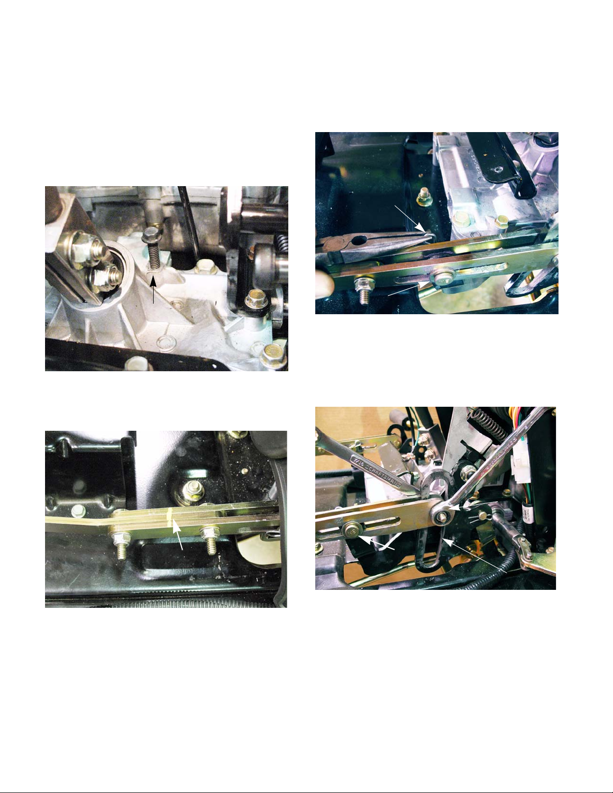
STEERING-IVT
2b. Using a 1/4”-20x2” bolt, thread it into the
steering box centering port until you feel it
touch the steering rack. While trying to gently thread the bolt further, slowly rotate the
steering shaft back and forth until the bolt
seats into the detent in the steering rack.
Finger tighten the screw to set the screw
fully into the detent. The steering gear box is
now centered and locked. See Figure 6B.2.
2” bolt
4. Loosen the two nuts and bolts on the drive control link.
5. Remove the bow tie clip and clevis pin from the
drive control link. See Figure 6B.4.
bow tie clip
Clevis pin
Figure 6B.4
6. Disconnect the drive control link from the right
side of the gear box only:
Figure 6B.2
3. Match mark the drive control link betwee n th e
two nuts and bolts. See Figure 6B.3.
Match mark
Figure 6B.3
NOTE: The match mark will make it easier to do
the neutral adjustment later on.
6a. Removing the nut and bolt.
See Figure 6B.5.
Remove this nut
and bolt
Clevis pin
Cam slot
Figure 6B.5
82
Page 89

STEERING-IVT
6b. Remove the bow tie and clevis pins.
6c. Raise the drive control link away from the
cam slot.
NOTE: Catch the double roller when lifting the
drive control link away from the steering gear
box. See Figure 6B.6.
Double roller
Figure 6B.6
8. Set the cam slot angle at 90o to the frame using
a combination square. See Figure 6B.8.
o
90
Figure 6B.8
9. Tighten the return to neutral bolt.
10. Adjust the transmission for neutral and align the
front wheels as described in the following sections of this chapter.
7. Loosen the return to neutral bolt using a 9/16”
wrench and a 1/4” hex key. See Figure 6B.7.
Return to neutral bolt
Figure 6B.7
83
Page 90

STEERING-IVT
Neutral and drive control links Adjustment
IMPORTANT: Check the tire air pressure before
attempting to diagnose any problems with the
steering or tracking of an I-series tractor. If the
tire air pressures are not equal across the same
axles, it will greatly affect the performance of the
tractor.
Because the steering gear box is linked to the
transmission, it is important to make sure the transmission is adjusted for neutral first. To establish neutral:
1. Remove the steering wheel by:
1a. Remove the center cover. See Figure 6B.9.
Center cover
NOTE: There is no puller needed for the steering wheel. Once the bolt is removed it will lift off
of the steering shaft.
2. Disconnect the parking brake by removing the
hair pin clip and sliding the rod out of the lever.
See Figure 6B.11.
Hair pin
clip
Rod
Figure 6B.11
Figure 6B.9
1b. Remove the bolt with a 1/2” wrench.
See Figure 6B.10.
Remove
this
bolt
3. Remove the two screws attaching the dash to
the dash support. See Figure 6B.12.
One on each side
Figure 6B.12
84
Figure 6B.10
Page 91

STEERING-IVT
4. Remove the two screws in the cargo net area, at
the bottom of the dash. See Figure 6B.13.
Remove these screws
Figure 6B.13
NOTE: The cargo net was removed for a clear er
picture. Do not remove the net to remove the
screws.
5. Remove the screws at the bottom of the dash,
on each side. See Figure 6B.14.
Screw removed
7. Lock Steering Gear Box in Neutral Position:
7a. Remove the 1/4”-20 plug screw from the
steering gear box centering port using a 3/8”
wrench. See Figure 6B.15.
2” screw
Figure 6B.15
7b. Using a 1/4”-20x2” bolt, thread it into the
steering box centering port until you feel it
touch the steering rack. While trying to gently thread the bolt further, slowly rotate the
steering shaft back and forth until the bolt
seats into the detent in the steering rack.
Finger tighten the screw to set the screw
fully into the detent. The steering gear box is
now centered and locked.
See Figure 6B.16.
Figure 6B.14
NOTE: Do not disconnect the wiring. Leave the
dash lose so that it can be lifted to remove the
fender.
6. Remove fender by following the steps described
in Chapter 4: Body/Chassis.
2” bolt
Figure 6B.16
85
Page 92

STEERING-IVT
8. Jack the tractor up so that both rear wheels are
off of the ground and place a pair of jack stands
under the rear transmissions.
9. Remove the rear wheels.
10. Wedge the brakes open on both sides of the
transmission. See Figure 6B.17.
Chisels used
to hold brakes
open
NOTE: If a tachometer is not available:
14a. Before starting the tractor, mark the brake
drum and shoe with a reference mark.
See Figure 6B.18.
Reference mark
Figure 6B.17
1 1. Make sure all tools and wires are away from any
moving parts.
12. Depress the brake pedal and start the tractor.
13. Release the brake pedal.
14. Measure the RPMs of the brake shaft on both
sides of the transmission.
The tractor engine and drive system
! CA UTION! CA UTION
Confirm that no hazards will be incurred by running the
engine or operating the drive system
must be operated to complete this
procedure.
Figure 6B.18
14b. Time how long it takes for the brake drum
to complete one revolution.
NOTE: The brake drum should be turning at
8RPMs or lower (more than 7.5 seconds per revolution).
NOTE: The closer to 0 RPMs the better the
steering performance will be.
86
Page 93

STEERING-IVT
If the transmission needs adjusted:
15. Turn off the engine.
16. Loosen the two nuts and bolts in the center of
the drive control linkage on the side that needs
adjusted . See Figure 6B.19.
Loosen these
nuts and bolts
Figure 6B.19
17. Depress the brake pedal and start the tractor.
18. Release the brake pedal.
19. Adjust the length of the drive control linkages
until the brake drum speed is less than 8 RPMs.
See Figure 6B.20.
20. Tighten the two nuts and bolts in the center of
the drive control linkage.
21. Reassemble the tractor.
NOTE: Leave the 1/4”-20x2” bolt thre aded in the
steering gearbox.
22. Perform the wheel alignment by following the
procedures described in the next section of this
manual.
Keep hands away from the fan and
! CAUTION! CAUTION
Keep hands
clear of the fan
NOTE: Holding the control link near the center
will help keep the technicians hands clear of the
fan and belt. See Figure 6B.20.
belt while the engine is running.
Grab at center
of the control link
Figure 6B.20
87
Page 94

STEERING-IVT
Wheel alignment
NOTE: The transmission neutral adjustment
must be done prior to adjusting the steering linkage.
1. Remove the three screws holding each steering
gear cover in place. See Figure 6B.21.
Remove
these screws
Figure 6B.21
3. Insert a 5/16” pin through the hole in the steering gear on each side. The pins should pass
through the gears, through the lower cover plate
and into the pivot bar. See Figure 6B.23.
5/16” punch
Figure 6B.23
NOTE: If the alignment is off, the holes may not
line up. If this is the case, adjust the front end by:
2. Rotate the front tires until the marks on the axle
gears and the steering gears align.
See Figure 6B.22.
Insert a 5/16” pin
here
Align the timing marks
Figure 6B.22
3a. Loosen the jam nuts on both ends of the
drag link. See Figure 6B.24.
Loosen both jam nuts
Figure 6B.24
88
Page 95

STEERING-IVT
3b. Adjust the drag link until the holes line up
See Figure 6B.25.
Rotate to lengthen or shorten
Figure 6B.25
NOTE: The punch should slide in and out with-
out binding. As the drag links are being adjusted,
rock the tires back and forth to remove the load
created from the tires twisting on the floor.
3c. Tighten the jam nuts.
4. Remove the 1/4”-20x2” screw from the steering
gear box.
5. Reinstall the original plug screw in the steering
gear box.
Steering gear box removal
To replace the gear box:
1. Remove the dash and fender by following the
steps described in Chapter 4: Body/Chassis.
2. Match mark the drive control link between the
two nuts and bolts. See Figure 6B.26.
Match mark
Figure 6B.26
NOTE: The match mark will make it easier to do
the neutral adjustment later on.
3. Remove the bow tie clip and clevis pin from both
drive control links. See Figure 6B.4.
6. Install the steering gear covers.
7. Install the dash and fender by following the procedures described in Chapter 4: Body/Chassis.
Never allow an I-series tractor to be
! CAUTION! CAUTION
8. Test drive the tractor in a safe area before
returning it to service.
! WA RNING! WA RNING
operated without the steering gear
covers. Personal injury may result.
Make sure all safety features are
working properly before returning
to service.
bow tie clip
Clevis pin
Figure 6B.27
89
Page 96
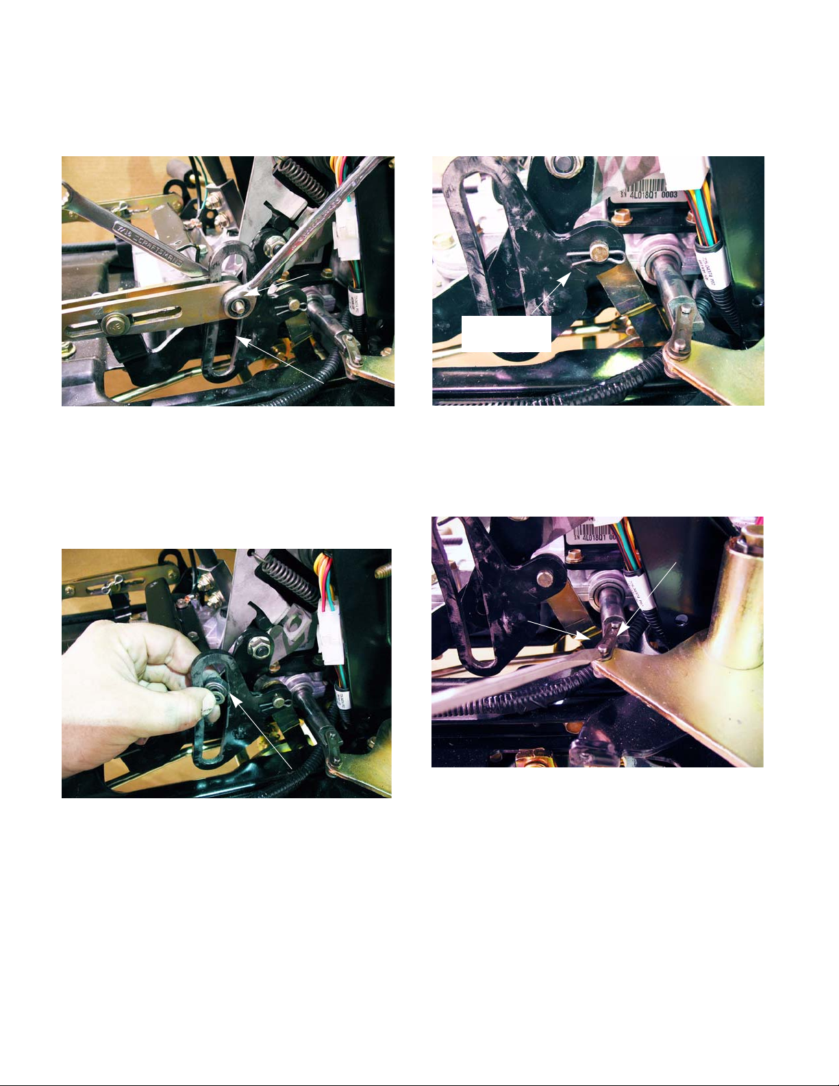
STEERING-IVT
4. Disconnect the drive control link from both sides
of the gear box by removing the nut and bolt.
See Figure 6B.5.
Remove this
nut and bolt
Cam slot
Figure 6B.28
5. Raise the drive control link away from the cam
slot.
NOTE: Catch the double roller when lifting the
drive control link away from the steering gear
box. See Figure 6B.6.
6. On the right side cam slot lever there is a connector link. Remove the hairpin clip.
See Figure 6B.30.
Remove hair
pin clip
Figure 6B.30
7. Disconnect the steering links on both sides:
7a. Gently pry the link retainer over the master
link. See Figure 6B.31.
Retainer
Figure 6B.29
Double roller
Steering link
Figure 6B.31
90
Page 97

STEERING-IVT
8. Remove the steering shaft by removing the two
clamp bolts in the steering shaft receiver and lifting the shaft out. See Figure 6B.32.
Steering shaft
Steering shaft
Receiver
Figure 6B.32
NOTE: Rotating the steering shaft bushing 90
degrees will allow the bushing to pop out relieving the pressure on the steering shaft. This will
make it easier to remove or install the shaft.
See Figure 6B.33.
9. Disconnect the ground wire. See Figure 6B.34.
Ground wire
Figure 6B.34
10. Remove the four screws holding the gear box to
the frame with a 1/2” wrench. See Figure 6B.35.
Rotate the bushing 90
Figure 6B.33
o
Figure 6B.35
11. Slide the gear box to the right to disconnect the
connector link, then lift out of the tractor.
12. The new gear box should come with 1/4”-20 x 2”
screw to lock it into the neutral/centered position.
13. Work the gear box so that the connector link can
be inserted into the hole in the cam slot lever.
14. Install the hair pin clip removed in step 5.
15. Bolt the gear box to the frame with the four bolts
removed in step 8.
16. Insert the steering shaft into the steering shaft
receiver. Tighten the nuts to a torque of 130 160 in lbs (15 - 18 Nm).
91
Page 98

STEERING-IVT
17. Attach the steering links. Install the retainers.
NOTE: If the retainers are bent or twisted, the
whole link must be replaced. The retainers are
not available separately.
18. Apply anti-seize compound to the rollers and the
cam slots on the gear box levers.
19. Adjust the speed cam angle by following the
step described in the cam slot angle section of
the chapter.
20. Connect the drive control links.
20a. Place the rollers into the cam slots and
slide the drive control links over the levers.
20b. Insert the bolt through the drive control link
and roller .
20c. Install the nut on the bolt and tighten to a
torque of 8 ft lbs (11 Nm).
21. Insert the clevis pin, washers and bow tie clips.
22. Align the wheels and adjust the drive control
links by following the steps described in the previous sections of this chapter.
23. Remove the 1/4”-20x2” bolt that came with the
steering gearbox and install the short one from
the old gearbox.
24. Install the fender and dash by following the steps
described in Chapter 4: Body/Chassis.
Rebuilding the steering gear box
To take the steering gear box apart:
1. Remove the steering gear box by following the
procedures described in the previous section of
this chapter.
2. Remove the return to neutral bolt using a 9/16”
wrench and a 1/4” hex key. See Figure 6B.36.
Figure 6B.36
3. Remove the return to neutral bracket using a
3/8” wrench. See Figure 6B.37.
25. Test drive the tractor in a safe area before
returning to service.
Make sure all safety features are
! WA RNING! WA RNING
working properly before returning to
service.
Remove these
screws
Figure 6B.37
92
Page 99

STEERING-IVT
4. Remove the six remaining case screws using a
3/8” wrench. See Figure 6B.38.
Remove
these
screws
Figure 6B.38
5. Lift the upper housing off of the lower housing.
NOTE: There is no sealant between the two
housings. They should easily slip apart. If they
are stuck together, there are three pry points
cast into the housings that can be used to separate the housings.
7. Separate the speed cam assemblies by driving
out the two roll pins using a 5/32” pin punch and
a hammer. See Figure 6B.40.
5/32” pin punch
Figure 6B.40
8. Separate the output bevel gear assembly by
removing the snap ring. See Figure 6B.41.
6. Remove the speed cam assemblies.
See Figure 6B.39.
Speed cam assemblies
Figure 6B.39
Remove this
snap ring
Figure 6B.41
93
Page 100

STEERING-IVT
9. Remove the input sector gear.
See Figure 6B.42.
Input sector gear
Figure 6B.42
10. Inspect the input sector gear bushings for damage and/or signs of wear. If they show signs of
wear or damage, press both of the bushings out
of the input sector gear using a press.
See Figure 6B.43.
11. Remove the internal cam and both of the washers on top of the cam. See Figure 6B.44.
Washers
Steering
shaft
Internal cam
Figure 6B.44
NOTE: The steering shaft is pressed into the
lower housing.
12. Remove both of the bevel gears.
See Figure 6B.45.
Press out the
bushings
Figure 6B.43
Bevel gears
Figure 6B.45
NOTE: There may be a pocket of suction
between the bevel gear and the lower housing
because of the grease. It may be necessary to
use a pry tool to lift the bevel gear out of the
lower housing.
94
 Loading...