

Page 1
O
perator’s
M
anual
Challenger 500\700
CUB CADET LLC, P.O. BOX 361131 CLEVELAND, OHIO 44136-0019
Form No. HS-01231401C
(December 4, 2017)
WARNING
READ AND FOLLOW ALL SAFETY RULES AND INSTRUCTIONS IN THIS MANUAL BEFORE ATTEMPTING TO OPER-
ATE THIS MACHINE. FAILURE TO COMPLY WITH THESE INSTRUCTIONS MAY RESULT IN PERSONAL INJURY.
Page 2
Owner’s Manual
WARNING: This symbol points out important safety instructions, which, if not followed, could
endanger the personal safety and/or property of yourself and others. Read and follow all instructions
in this manual before attempting to operate this machine. Failure to comply with these instructions
may result in personal injury
When you see this symbol, HEED ITS WARNING!
WARNING: Engine Exhaust, some of its constituents, and certain vehicle components contain or
emit chemicals known to State of California to cause cancer and birth defects or other reproductive
harm.
WARNING: Battery posts, terminals, and related accessories contain lead and lead compounds,
chemicals known to the State of California to cause cancer and reproductive harm. Wash hands after
handling
DANGER: T his machine was built to be operated according to the rules for safe operation in this
manual. As with any type of power equipment, carelessness or error on the part of the operator can
result in serious injury. Failure to observe the following safety instructions could result in serious injury
or death
.
Page 3

Owner’s Manual
INTRODUCTION
Congratulations on your purchase of the Cub Cadet Challenger U TV . Th i s Owner’s / Operator’s manual
will provide you with information regarding safe operation, operational inst ructions, maintenance and care.
Fully understanding this manual and following all of the instructions herein will provide the knowledge
needed to have safe and enjoyable UTV operation.
If you have any ques tion s re gar din g the operation or maintenance of your UTV, please consult
your Cub Cadet dealer.
IMPORTANT SAFETY MESSAGES
●
READ THIS MANUAL CAREFULLY AND COMPLETELY BEFORE OPERATING YOUR UTV. MAKE SURE
YOU UNDERSTAND ALL INSTRUCTIONS.
●
PAY CLOSE ATTENTION TO THE WARNING AND CAUTION LABELS ON THE UTV.
●
NEVER OPERATE THE UTV WITHOUT PROPER TRAINING OR INSTRUCTION.
●
THIS UTV SHOULD NOT BE OPERATED BY ANYONE UNDER 16 YEARS OF AGE.
Page 4
Owner’s Manual
IMPORTANT MANUAL INFORMATION
FAILURE TO FOLLOW THE WARNINGS CONTAINED IN THIS MANUAL CAN RESULT IN SERIOUS INJURY
OR DEATH. Particularly important information is distinguished in this manual by the following
notations:
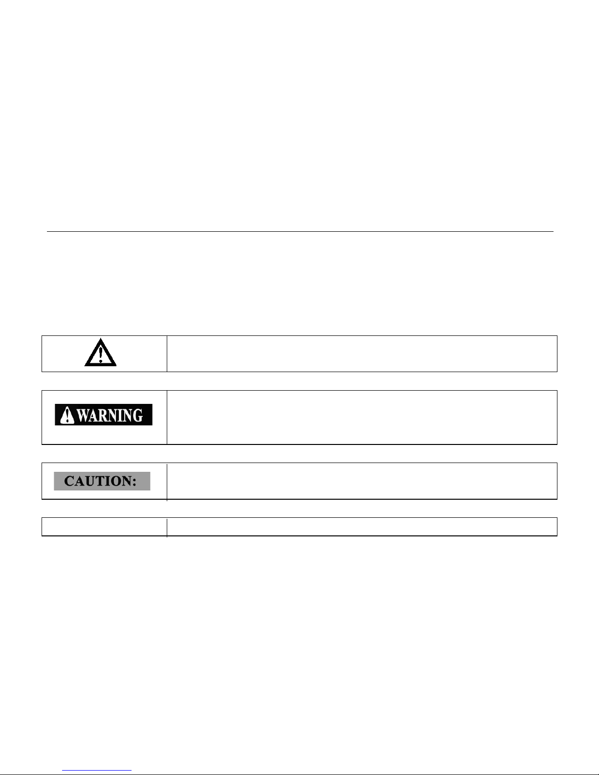
The Safety Alert Symbol means ATTENTION!
YOUR SAFETY IS INVOLVED!
Failure to follow WARNING instructions could result in severe injury or death to
the machine operator, passengers, bystanders, or any person inspecting or
repairing the machine.
A CAUTION indicates special precautions that must be taken to avoid damage
to the machine.
NOTE:
A NOTE
provides key information to make procedures easier or clearer
.
Page 5

Owner’s Manual
IMPORTANT NOTICE
This UTV is designed and manufactured for OFF - ROAD use only. It is illegal and unsafe to operate this
UTV on any public street, road or highway.
This U TV complies with all applicable OFF - ROAD noise level and spark arrester laws and regulations in
effect at the time of manufacture.
Please check your local riding laws and regulations before operating this UTV.
When the temperature is below -4°F (-20°C), park the UTV in a place where the temperature is higher
than -4°F (-20°C). Start the UTV after the UTV has warmed up. Please see page 6-3 on the warming up
process.
Follow the proper parking procedures when the temperature is higher than 100°F (38°C): turn off the
engine; make sure the radiator fan is on for 3 minutes before turning off the power switch.
Starting the UTV for the first time will take longer because the fuel will need reach the fuel injectors. To
start the UTV the first time, hold the ignition key on at 5-second intervals. Allow the starter to rest 15
seconds between each start attempt.
Page 6

1
Location of the Warning and
Specification Labels
Owner’s Manual
1-1
Accelerator Pedal
4-14
Brake Pedal
4-15
Parking Brake Lever
4-16
2
Safety Information 2-1
Description and Vehicle
3-1
Identification
Drive Select Lever
4-17
Fuel Tank Cap
4-17
Seats
4-18
On-Command Four-Wheel-Drive and
3
Identification Number Records 3-3
Seat Belts
4-19
Vehicle Identification Number
3-3
Glove Compartment
4-21
Cargo Bed
4-22
4
Control Functions
4-1
Opening and Closing the Tailgate
4-22
Main Switch
4-1
Lifting and Lowering the Cargo Bed
4-23
Indicator and Warning Lights
4-2
Front and Rear Shock Adjustment
4-25
Use of EPS system
4-4
Spring Preload
4-28
Speedometer Unit
4-5
Rebound Damping Force
4-29
Odometer and Trip Meter Modes
4-6
Compression Damping Force
4-30
Fault code indicator
4-8
Trailer Hitch Bracket
4-31
Fuel level indicator
4-9
Auxiliary DC Jack
4-31
Switches
4-10
5
Pre Operation Checks
5-1
Differential Gear Lock Switches
4-11
Brakes
5-2
Page 7

Owner’s Manual
3
0
2
Brake Fluid Level
5-2
Tire Wear Limit
5-1
Brake Fluid Leakage
5-3
Brake Operation
5-3
6 Operation 6-1
Fuel
5-4
Starting the Engine in Low
6-1
Gasohol
5-4
Temperatures
Engine Oil
5-5
Starting the Engine
6-2
Coolant
5-6
Warming Up
6-3
Final Gear Oil
5-7
Drive Select Lever Operation and
Differential Gear Oil
5-7
Driving In Reverse
Throttle Pedal
5-8
Parking
6-8
Throttle Freeplay
5-9
Parking on a Slope 6-8
Throttle Freeplay Inspection
5-9
Vehicle Break-in Period
6-9
Throttle Freeplay Adjustment
5-9
Engine Break-In 6-1
Steering Wheel Inspection
5-10
Accessories 6-11
Seat Belts
5-10
Loading
6-1
Fittings and Fasteners
5-10
Lights
5-10
7
Driving Your Vehicle 7-1
Switches
5-11
Getting to Know Your Vehicle
7-1
Tires
5-11
Learning to Operate Your Vehicle
7-5
How to Measure Tire Pressure
5-12
Turning your Vehicle
7-6
Page 8

Owner’s Manual
8
Engine Oil and Oil Filter Cartridge 8-12
Braking
7-8
To Check the Engine Oil Level
8-13
Going Uphill
7-8
To Change the Engine Oil
8-14
Going Downhill
7-10
Final Gear Oil
8-17
Crossing Through Shallow Water
7-12
Checking the Final Gear Oil Level
8-17
Riding Over Rough Terrain
7-15
Changing the Final Gear Oil
8-18
Riding in Brush or Wooded Areas
7-17
Differential Gear Oil
8-19
Encountering Obstacles on the Trail
7-17
Checking the Differential Gear Oil
Level
8-19
Changing The Differential Gear Oil
8-20
Periodic Maintenance and
8-1
Coolant
8-21
Adjustment
Axle Boots
8-23
Periodic Maintenance Chart for the
Spark Plug Inspection
8-23
Emission Control System
Removal
8-23
General Maintenance and Lubrication
Inspection
8-24
Chart
Installation
8-25
Hood
8-7
Cleaning the Air Filter Ele ments
8-26
Console
8-8
V-belt Cooling Duct Check Hose
8-30
EFI System
8-9
V-belt Case Drain Plug
8-30
ECU
8-12
Cleaning the Spark Arrester
8-31
EFI System Inspection
8-12
Valve Clearance
8-33
Page 9

Owner’s Manual
Front Brake Pad Check 8-33
Rear Brake Pad Check 8-34
Checking the Brake Fluid Level 8-34
Brake Fluid Replacement 8-35
Checking the Brake Pedal
8-35
Parking Brake Lever Free Play
8-37
Adjustment
Brake Light Switch Adjustment
8-38
Cable Inspection and Lubrication
8-39
Headlight Beam Adjustment
8-50
Tail/Brake Light Bulb Replacement 8-51
Troubleshooting 8-53
Solution to Common Problems in the
Vehicle 8-54
Cleaning and Storage 9-1
Cleaning 9-1
Storage
9-3
Brake Pedal and Accelerator Pedal
Lubrication
Rear Knuckle Upper and Lower Pivot
8-40
8-40
Specifications 10-1
Lubrication
Steering Shaft Lubrication
8-41
Wheel Removal
8-41
Fault code of Electronic Injection
System
USA EPA Emissions Limited
11-1
Wheel Installation
8-42
Battery
8-43
Battery Maintenance
8-45
Fuse Replacement
8-45
Replacing Headlight Bulb
8-47
Warranty and Standard Warranty
12-1
9
Page 10
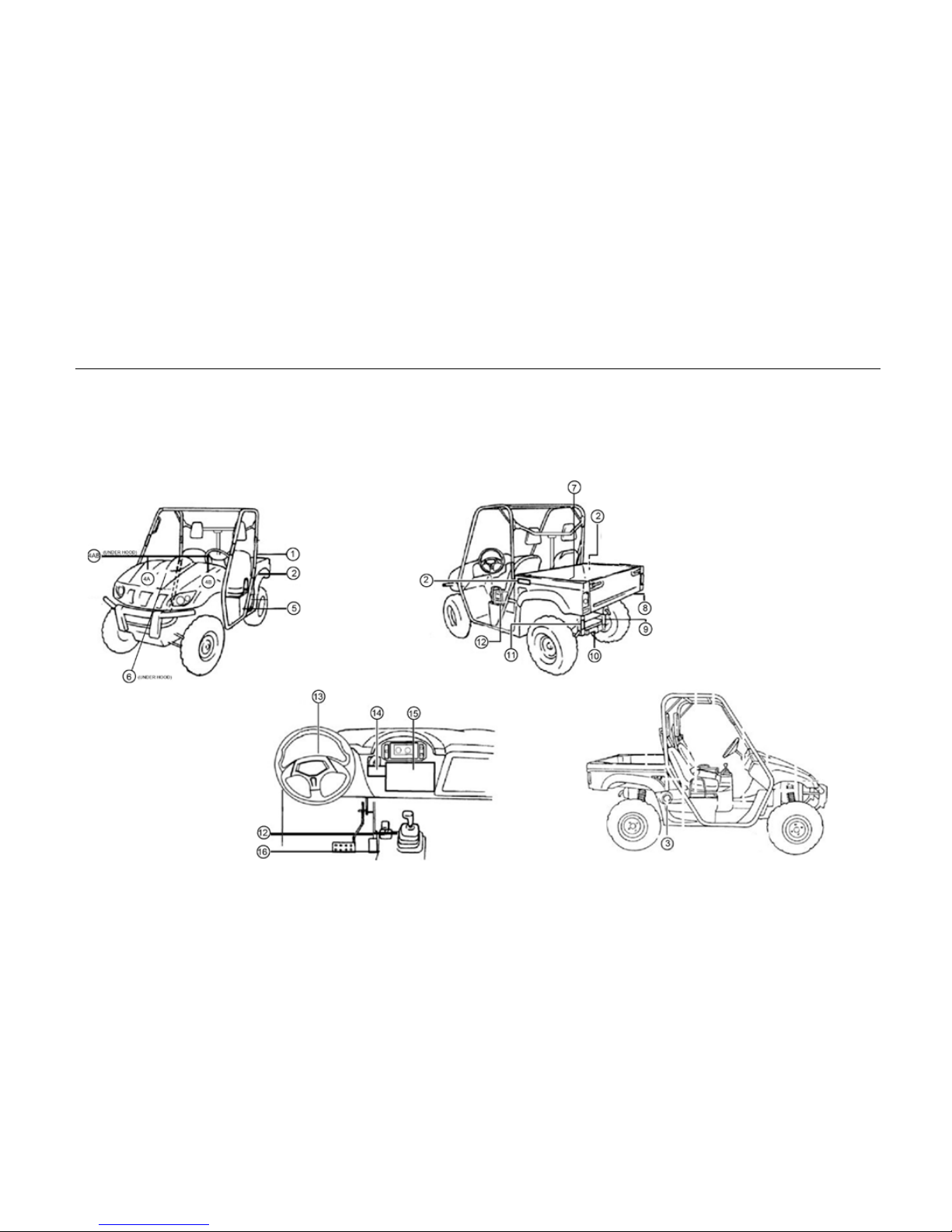
1-1 Location of the Warning and Safety Labels
Read and understand all of the labels on your vehicle. They contain important information for safe
and proper operation of your vehicle.
Never remove any labels from your vehicle. If a label becomes difficult to read or comes off, a
replacement label is available by contacting your dealer.
Page 11
Location of the W ar ni ng and Safety Labels
1-2
1
' Chongqi ng H uansong Science And Te chnol ogy I ndust r i al Co.,Ltd:
2 '
This structureme e ts ROPSr e q u ir emen ts
for
earth-moving machinery under ISO 3471 .
3
4A
,
4B
5
A
CAUTION
•Use only 91 Octane or higher
gasoline (E-10 max).
•Use Non-Ethanol gasoline when
possible for better engine
performance.
•NEVER USE E-85 gasoline, it
will damage the engine and void
the warranty.
VEHI CLE EM 1S8' 0N CO NTROL INFORM ATION
C UB CADE T L LC
ENGINE DfSPL ACEMENT :
ENGINE FAMILY:
ENGINE EXHAUST CONTROL SYSTEM:
PERM FAMILY:
FIEMD
SFl,TWC, HIX!S
ENGINETUNEUP
SPECIFICATtoNS :
IDLE MIXTURE : NON ADJUSTABLE
O
THPIESRVEAS.
O
THIS
VE I
REGUL
AS
CE
.
E
F 201 0 L
YEAR NEW
UTVS ANO IS CERTIFIED
TO 1.5 G/KM
HC + NOX, 35 GIKM CO
EXHAUST EMISSION STANDARDS
li
E
_
...
,, ,
MM
: . M
• UST.ABLE
MANUFA C TUR ED IN CHINA
IDLE SPEED: t 500 + 150 RPM
FUEL
: UNLEADED GASOLINE ONLY · 91
(R+M),"1 OCTANE OR
HIGHER
O
IL: t0W40
SEE OWNER·s MANUA L
CuJ.OuJee .
.,_
A .W....,.A......,R......,N l..,N...,.G
----t
•Keep hands and body safely
V
away when closing bed..
•NEVER operate the vehicle
with the bed up.
A
WARNING
;,
rne ;w'""" '"
''"'"d" 4w
:;:
:i h:ba l1r•
1
for
Ba el,t y
'\.,
Exhaustop ennig
Take off1herubber,u ling
capandromovof,llin . plu s
.
RoplaconibtHircapw,1h
R&mov• rul>btro • p
e
xhaust 1ub& or<ivlded
Filling elec1roly1e(acid)
f
Conneot a,hauottu be
Gr av ityof , coo!ortemperateclimale 1.270-1.280
trop 1c a l climate 1.250-1 .260
The electro
lyte temperature when fill ing mus t not be lower than 1s•c
or higher than JO" C
.
Fi
ll batter y to upper level as indicatedon the ba tterycase
Lea ve b a ttery tostand foratleast J Om
i nu tes afle r fi lling
Elect rol yte
l evelm a yf all during th isper iod. refill to upperlevel
before charg ing
Tnebatterycontar1sorerntschemcalsknown1ncertil1nqua1t1\es
to cause cancer b rthdefects o r otherre roduct 1ve harm
Improper tire pressur e or o verloading
can cause loss of control .
Loss of control can re sult in sev ere
injur y or death.
•
Cold tire pressure:
Fr on t . 10psi (70kPa )
Rear : 10psi (70kPa)
•
Ma xi mu m wei gh t cap acity:880 Ibs.(399kg )
A
WARNING
Page 12
1-3
Location of the Warning and Safety Labels
6 8
Cert1f1es tha t this ROV complies with theAmencan National Standard for
Recreational Off-Highway Vehicles, ANSI/ROHVA 1-2011 Standard
TYPE OF VEHICLE UTV
AWARNING:
EXHAUST F UMES MA Y CAUSE HARM
Engine exhaust from this product contains chemicals, known in certain
quantities to cause cancer, birth defects, or other reproductive harm.
7
9
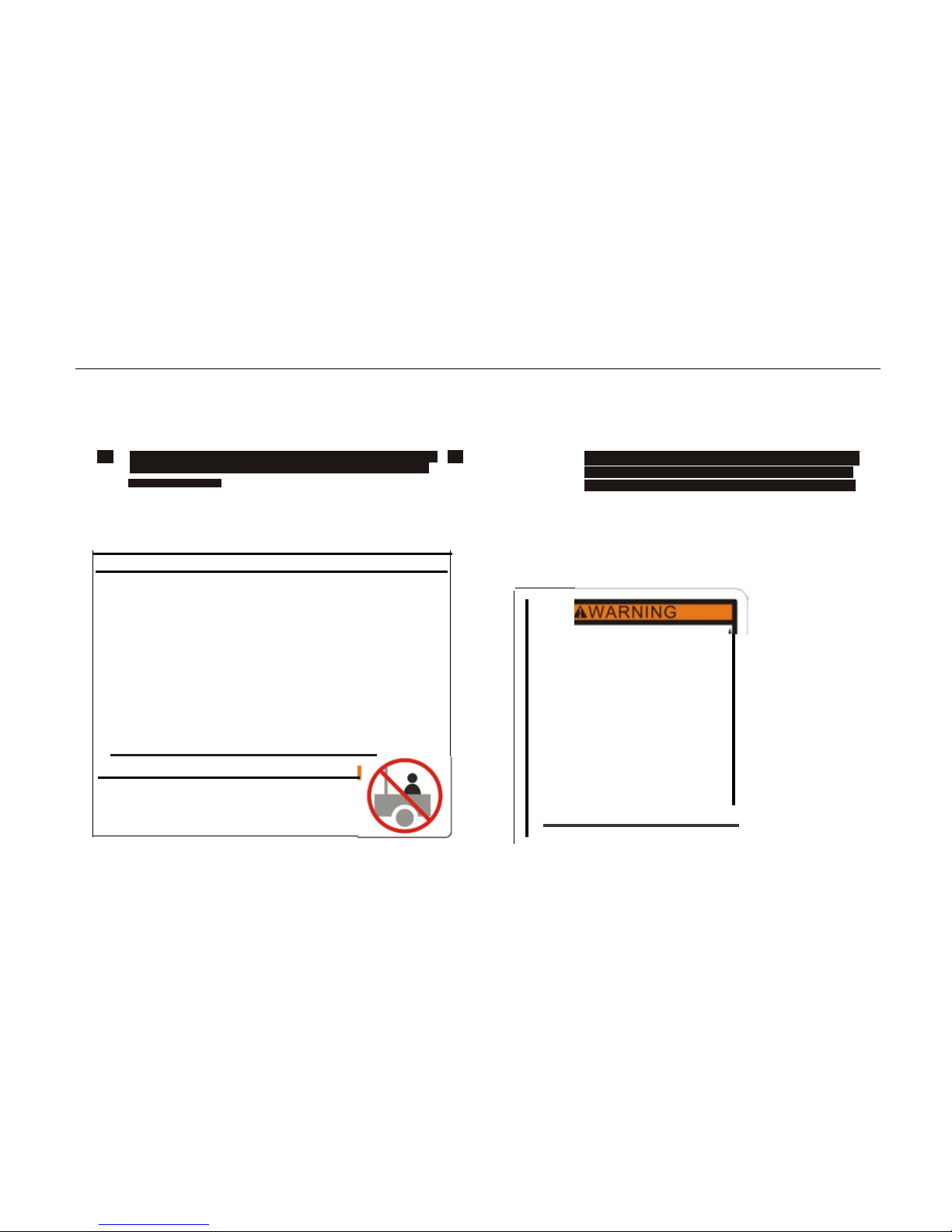
WARNING
Severe INJURY or DEATH can result if you ignore
the following guideline s :
•
Maximum load in cargo bed is 3501b ( 159kg )
• Never carry passengers in cargo bed. Passengers can
be thrown off causing serious injury or death.
•
Cargo can affect handling and stability.
•
Read Owner's Manual b ef ore loading or towing _
• When operating with cargo or towing a trailer always
reduce speed, allow more room to stop and avoid hills
and rough terrain _
•
Be
sure cargo is secured sinc e a loose load can
change vehi cle handling _
•
Keep weight in the cargo bed centered and as low and
as far for wa rd as possible.
•
Top-heavy l oads increase the risk of rollover.
WARNING
NEVER CARRY PASSEN G ERS
IN CARGO BED.
• Operat ion of this equipmen
may create sparks that can
start fires around dry
vegetation.
•
A spark arrester may be
required . The operator
should contact local fire
agencies for laws or
regulati ons relating to fire
prevention requirementsdj
- •
Page 13
•
Max towing weight:544kg(1200Ibs
•
Max tongue weight:50kg( 11Olbs)
Location of the Warning and Safety Labels 1-4
11
10
)
12
I
• •
•
_j -- .. ...
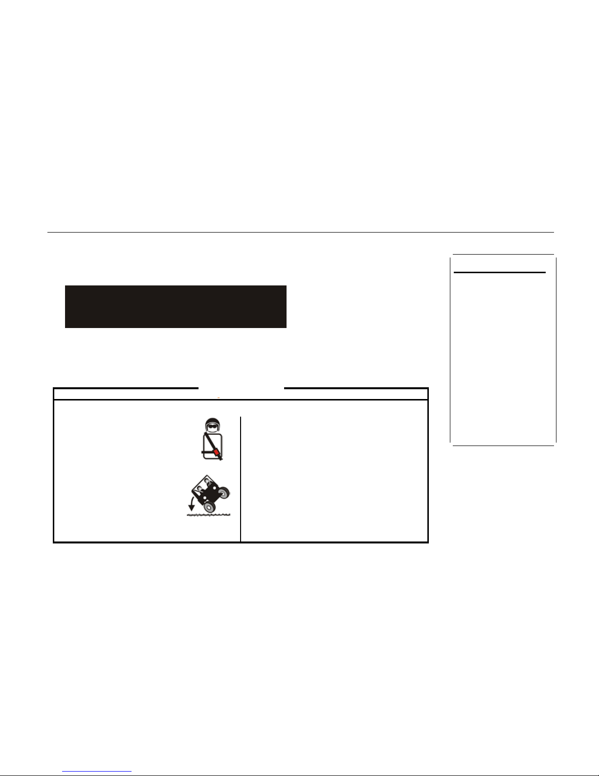
Improper Use of Off-Highway Vehicles Can Cause Severe Injury or Death
Be Prepared
•Fasten seatbelts.
•
Wear anappr oved h el m et an dp rotec tiv ege ar.
•
Eachrider must beablet os it withback ag ai ristseat,
feetflatonfloor[andfootrests],andhandsonsteering
wheel or handhold[s ](,wh ereequ ippedl, S1ay
completely inside t he vehicle.
Drive Respons ibly
Avoid losso fcontro l and rollovers:
•
Avoidabruptm aneuvers, sidew ayss lld ing, sklddi ng,
orfishta iling, andneverdodonuts.
• Slowdownbeforeenteringaturn.
•
Avoidh arda cceleration whentu rning, even
from a stop.
•
Pla nfor hills, rou ghterrai n, rut s, andoth er
changesintractionan d te rrain. Avoid
Rollovers have caused
paved surfaces.
seyerein juriesand death,
•
Avoidsidehilling( r idingacrossslopes ).
eYeno n fl at, open areas,
Be
Sure Riders
Pay
Attent
i on and
Plan
®
Ahead
If youthinkorfeelthe vehiclemayti por roll, reduceyour risk to injury:
•
Keep afi rmgriponthesteeringwheelor handholdsa ndbrace yourself.
•
Donot putanyp art ofyour b odyoutsideofthevehi cl ef oranyreason .
Require Proper Us e of Y our V e hicle
Doyou r part toprevent in1ur1es VER
•
Donot all ow carelessorreck less driving
•
Mak esureope rato
rs
arel
6orolder w1t ha vahd
U R
drivers license
1
•
Donot let peopl ed n ve or nd e after usmgalc oh ol or dr u gs
• Donot al l
owope
rat 1
ononpub l1
croads(unlessdes 1gnated
for
off-highwayvehicleaccess)··collisionswithcarsandtruckscanoccur.
•
Donot exceeds eatingcapacity: !passenger.
[Locate and] Rea d [ Owner 's Manual]
Follo w All I nstruct i on and Warning s
[ Reserve d for Ref ere nce t o Oth er Sou re s of Saf ety I nf o rmat i on ]
WARNING
•Improperly loading a
trailer and fail ure to use
extra care when pulling
trailer can cause an
accident or injury.
•
Never load more than
1101b s
(50kg) tongue
weight on the to wing
bracket.
• Do not tow more than
1200lbs (544kg) rolling
weight (trailer plus cargo).
• Operate in low-range
gears only, allow for
increased braking
distance, and use
extreme caution when
operating on inclines.
• Read carefully the
loading information and
trailer hitch sections in
the owners manual.
Page 14
1-5 Location of the Warning and Safety Labels
13
u
'14
---
A
-
WA-RN-ING
--'---
15
A.WARNING
You could be severely injured if you try to stop
a vehicle roll over using your arm or leg.
If vehicle st arts to rollover, keep arms and legs
inside vehicl e.
16
Operation takes more effort whil e the veh icle
is in 4W D -LOCK.
When in 4WD-LOCK ope ra te a t a slo w
speed
and allow extra time and di stance for
turns to
avoid loss of control.
Select gear "L"on
rough terrain and
sloped terrain.
ACAUTION
AWARNING
•
Do not drive in the water deeper than 15 in
•
Turn speed not to exceed 18 MPH/30 KPH
Page 15

Safety Information 2-1
Operation
General O p eration
Read, understand, and follow all instructions on the vehicle and in the manual before attempting to operate or service vehicle.
Keep this manual in a safe place for future and regular r eference and for ordering replacement parts.
This is an off-road utility vehicle and it should not be operated on public highways. Know and comply with all laws and
regulations governing the use of off-highway vehicles in your area.
This vehicle handles and maneuvers differently than a normal passenger car. Sharp high speed turns and abrupt maneuvers
can cause vehicle to roll over or go out of control. Slow down when turning and avoid abrupt maneuvers.
Handling and maneuvering characteristics of vehicle change depending upon cargo load. Heavy loads affect steering, braking,
stability, and overall handling of vehicle.
Be familiar with all instructions and controls and their proper operation before starting vehicle.
Never allow adults to operate this vehicle without proper instruction.
Page 16

2-2 Safety Information
Never allow children under 16 years old to operate this vehicle. Children 16 years old and over should read and understand the
operation instructions and safety rules in this manual and should be trained and supervised by a parent.
Watch for traffic when operating near or crossing roadways. This vehicle is not intended for use on any public roadway.
Do not operate this vehicle while under the influence of alcohol or drugs.
Never carry more passengers than the vehicle is designed to carry. Do not allow any passengers to ride in the cargo bed. All
passengers must be seated with their seat belts fastened at all times..
Keep all body parts (i.e. head, arms, hands, legs, feet) inside vehicle when vehicle is in motion.
Always remain seated and keep both hands on the steering wheel when driving the vehicle.
Sit on the center of the seat and keep both feet within the foot platform perimeter. Clean foot platform if dirty and remove any
debris from around foot controls, e.g. brake pedal.
Do not misuse the utility vehicle. It is an utility vehicle, not a recreation vehicle or toy. Recreational riding can lead to accidents,
severe bodily injury or death.
Page 17

Safety Information 2-3
Inspect area around vehicle before moving, especially in reverse. Back up slowly. Always look down and behind before and
while backing to avoid a back-over accident. Keep bystanders out of area.
Avoid driving through water, since loss of control may occur. Drive belt may slip if exposed to water thus reducing vehicle
pulling power and stopping vehicle entirely.
Always use vehic le lights while operating inlow l ight situations.
Do not mount or leave vehicle while it is in motion or in actual operation.
Avoid sudden starts, stops, or turns and always use a level turn-around area.
Never leave vehicle unattended with the key in the ignition. Always turn key to the "Stop" position, set the parking brake and
remove key.
Check overhead clearances carefully before driving under low hanging tree branches, wires, power lines, bridges, before entering or
leaving buildings, or in any other situation where the operator and/or operator protective structure (OPS) may be struck,
which could result in serious injury.
Page 18

2-4 Safety Information
Use the operator protective structure (OPS) and seat belt for safe operation. Overturning the utility vehicle without an operator
protective structure (OPS), or with an operator protective structure (OPS) and the seat belt unfastened, can result in death
or injury.
Always use the s eat belt, except if the operator protective structure (OPS) has been removed.
The doors and nets are designed to assist in keeping the operator and passenger inside the vehicle during operation. Do not
operate vehicle without doors and nets in place and properly secured.
Improper use of the vehicle or failure to properly maintain it could result in decreased vehicle performance or personal injury.
Engine must be stopped when cleaning, servicing, adjusting, repairing, or installing attachments on utility vehicle.
After striking foreign objects stop the unit and shut off the engine. Inspect for damage and repair the damage before restarting
and operating equipment.
Do not start or operate vehicle in an inside area, unless it is adequately ventilated. Engine exhaust contains carbon monoxide
fumes, which are very poisonous and can be deadly.
Do not change engine governor setting or over -speed the engine. The governor is set at the factory for safe operating speed.
Page 19

Safety Information 2-5
Assure safety interlock switch is adjusted correctly so engine cannot be started unless gearshift is in the neutral position.
Do not touch engine or muffler while engine is running or soon after it is stopped. They will be hot and can cause a burn.
Always inspect your vehicle each time you use it to make sure it is in safe operating condition. Always follow the inspection and
maintenance procedures and schedules described in this manual.
If situations occur which are not covered in this manual, use care and good judgment. Contact your local service center or call
toll free 1-877-282-8684for the name of your nearest service center.
Occupant Size and Capacity
Make sure operat ors are at least 16 years old and have a valid driver' s license.
Each occupant should be able to sit with their back against the seat, feet flat on the floor, and hands on the steering wheel or
handholds.
The operator should be tall enough to wear the seat belt properly and reach all contr ols.
Passengers should also be tall enough for the seat belt to fit properly and be able to brace themselves, as necessary, by placing
both feet firmly on the floor while gripping the handholds. Keep all body parts completely inside the vehicle.
Page 20
2-6 Safety Information
Dress Properly
Slope Operation
Do:
Page 21

Avoid slopes with slippery, loose, or bumpy surfaces as they are especially hazardous.
Safety Information 2-7
Use extra care while carrying c argo.It may affect the stabili ty of the vehicle. Spread the load evenly or tie down.
Do Not:
Do not travel near drop-offs, ditches or embankments. The vehicle could suddenly overturn if a wheel is over the edge of a cliff,
ditch, or if an edge caves in.
Do not stop or start suddenly when going uphill or downhill. Be especially cautious when changing direction on slopes.
Do not turn sideways to the hill.The vehicle may roll over. If you must turn, go slow and do so carefully and gradually.
Do not carry cargo on steep slopes or tow loads.
Towing
Always use an approved hitch and hitch point provided on the utility vehicle.
Do not tow more than 1200 lbs. rolling weight (i.e. trailer plus cargo).
Never load more t han 110 lbs. tongue wei ght on tow bracket provided.
Page 22
2-8 Safety Information
Cargo Box Loading/Operation
Page 23

Safety Information 2-9
Avoid sudden starts, stops, and turns which could cause load to shi ft.
Cargo Box Lift
Stop vehicle on level ground and set Parking Brake before raising cargo box.
On manual lift units, unload cargo box before raising cargo box.
Do not operate vehicle with c argo box in raised position.
Do not operate vehicle with c argo box latch unlatched. Always re-latch upon manuall y lowering cargo box.
Safety Frame (OPS)
Your vehicle is equipped with a operator protective structure (OPS) which must be maintained in a fully functional condition.
Use care when driving through doorways or spaces with a low overhead.
Never modify the OPS in any way.
Page 24

2-10 Safety Information
Never attempt to straighten or re-weld any part of the main frame or retaining brackets that have been damaged.
Doing so may weaken the structure and endanger your safety.
Never secure any parts other than Cub Cadet approved accessories on the main frame or attach the safety frame with
anything other than the special fasteners specified.
Never attach ropes, chains, or cables to the OPS for pulling purposes.
Although the OPS, when used with a properly secured seat belt, provides a crush-protective environment in the event
of a tip-over or rollover, never take unnecessary risks.
Children
Tragic accidents can occur if the operator is not alert to the presence of children. Children are often attracted to the vehicle. They
do not understand the dangers. Never assume that children will remain where you last saw them. Avoid run-over
accidents.
Page 25

Safety Information 2-11
Keep children out of the immediate area of the vehicle and in watchful care of a responsible adult other than the
operator.
Be alert and turn t he vehicle off if a child enters t he area.
Before and while backing, look behind and down for small children.
Never carry s m all children, t hey m ay fall off and be seriously injur ed or interfere with safe vehicle operation.
Use extreme care while approaching blind corners, doorways, shrubs, trees or other objects that may block your vision
of a child who may run into the path of the vehicle.
Remove key when ve hicle is unattended to prevent unauthorized operation.
Never allow children under 16 years old to operate this vehicle. Children 16 years old and over should read and understand the
operation instructions and safety rules in this manual and should be trained and supervised by a parent.
Do not let children ride in the cargo box, in the driver's or passenger's lap or anywhere other than the passenger seat. Never
give small children a ride; not even in the passenger seat. They may fall off.
Page 26
2-12 Safety Information
Safe Handling Of Fuel:
Page 27

Safety Information 2-13
Keep the nozzle in contact with the rim of the fuel tank or container opening at all times until fueling is complete. Do
not use a nozzle lock-open device.
Extinguish all cigarettes, cigars, pipes and other sources of ignition.
Never fuel machine indoors.
Never remove gas cap or add fuel while the engine is hot or running. Allow engine to cool at least two minutes before
refueling.
Never overfill fuel tank Fill tank to no more than½ inch below bottom of filler neck to allow space for fuel expansion.
Replace fuel cap and tighten securely.
If fuel is spilled, wipe it off the equipment. Move unit to another area. Wait 5 minutes before star ti ng the engine.
To reduce fire hazards, keep engine compartment and exhaust system free of grass, leaves, or other debris build-up.
Clean up oil or fuel spillage and r em ove any fuel soaked debris.
Never store the machine or fuel container inside where there is an open flame, spark or pilot light as on a water heater,
space heater, furnace, clothes dryer or other gas appliances.
Page 28

2-14 Safety Information
General Service
Never run an engine indoors or in a poorly ventilated area. Engine exhaust contains carbon monoxide, an odorless, and deadly
gas.
Before cleaning, repairing, or inspecting, make certain all moving parts have stopped. Disconnect the spark plug wires and
ground against the engine to prevent unintended starting.
Check brake oper ation frequently as it is subject ed to wear during nor m al operation. Adjust and service as required.
If equipped, the cooling system is under pressure. Never remove the radiator cap when the system is hot. Slowly turn the cap to
the first stop to release pressure before removing the cap.
Keep all nuts, bolts, and sc r ews tight to be sure th e eq u i pm e nt i s i n saf e w o rking condition.
Never tamper with the safety interlock system or other safety devices. Check their proper operation regularly.
Never attempt to make adjustments or repairs to the machine while the engine is running.
Do not change the engine governor settings or over-speed the engine. The governor controls the maximum safe operating
speed of the engine.
Page 29

Maintain or replace safety and instruction labels, as necessary.
Safety Information 2-15
According to the Consumer Products Safety Commission (CPSC) and the U.S. Environmental Protection Agency (EPA), units in
this product category have an Average Useful Life of seven (7) years, or approximately 400 hours of operation. To
extend the life of your unit, and specifically after (7) years of ownership or at 400 hours of operation, have the unit
inspected annually by an authorized service dealer to ensure that all mechanical and safety systems are working properly
and not worn excessively. Failure to do so can result in accidents, injuries or death. See Section 5 of this Operators
Manual for Maintenance and Service schedules.
Observe proper disposal laws and regulations for gas, oil, etc. to prot ect the environment.
Prior to disposal, determine t he proper method to di spose of waste from your local Environmental Protection Agency.
Recycling centers are established to properly dispose of mater ials in an environm entally safe fashion.
Use proper containers when draining fluids. Do not use food or beverage containers that may mislead someone into drinking
from them. Properly dispose of the containers immediately following the draining of fluids.
Page 30

2-16 Safety Information
DO NOT pour oil or other fluids into the ground, down a drain or into a stream, pond, lake or other body of water. Observe
Environmental Protection Agency regulations when disposing of oil, fuel, coolant, brake
fluid,
filters, batteries, tires and
other harmful waste.
Do not modify engine
To avoid serious injury or death, do not modify engine in any way. Tampering with the governor setting can lead to a runaway
engine and cause it to operate at unsafe speeds. Never tamper with factory setting of engine governor.
Notice Regarding Emissions
Where applicable, this vehicle is certified to federal EPA and California Air Resources Board (CARB) emissions standards for
Off-Highway Recreational Vehicles (OHRV). The engine owner's manual is supplied by the engine manufacturer, and
provides additional information relating to the emission system, warranty, and maintenance of the engine in accordance
with EPA and/or CARB regulations. Consult your engine manual for the fuel requirements for your engine.
Page 31

Safety Information 2-17
Gasoline powered products may be equipped with the following emission control systems: Please contact Customer Support
for information regarding the evaporative emission control configuration for your model.
Spark Arrestor
WARNING: This unit is equipped with an internal combustion engine and should not be used on or near any unimproved
forest-covered, brush-covered or grass-covered land unless the engine's exhaust system is equipped with a spark arrestor
meeting applicable local or state laws (if any).
If a spark arrestor is used, it should be maintained in effective working order by the operator. In the State of California the above is
required by law (Section 4442 of the California Public Resources Code). Other states may have similar laws. Federal laws
apply on federal lands.
A spark arrestor for the muffler is available through your nearest engine authorized service dealer or contact the service
department, P.O. Box 361131 Cleveland, Ohio 44136-0019.
Page 32

2-18 Safety Information
Page 33

3-1 Description and Vehicle Identification
1. Headlights
2. Front shock absorber assembly adjusting ring
3. Brake fluid reservoir
4. Air filter element(engine and air intake duct)
5. V-belt case
6. Driver seat
7. Driver seat belt
8. Spark plug
9. Cargo bed
10. Tail/brake lights
11. Rear shock absorber assembly adjusting ring
12. Cargo bed release levers
13. Spark arrester
14. Passenger seat belt
15. Passenger seat
16. Oil filter cartridge
17. Engine oil dipstick
18. Battery
19. Fuses
20. Coolant reservoir
21. Radiator cap
22. Fuel tank cap
Page 34

NOTE:
The vehicle you have purchased may differ slightly from
those in the figures of this manual.
Description and Vehicle Identification 3-2
23. Light switch
24. Steering wheel
25. Starter
26. Main switch
27. On-Com mand four-wheel-drive and differential lock
switches
28. Multi-function meter unit
29. Auxiliary DC jack
30. Drive select lever
31. Parking brake lever
32. Accelerator pedal
33. Brake pedal
Page 35

3-3 Description and Vehicle Identification
Identification Number Records
Record the Vehicle Identification Number and
model label information in spaces provided for
assistance when ordering spare parts from a
service center or for reference in case the
vehicle is stolen.
1. VEHICLE IDENTIFICATION NUMBER:
2. MO DEL LABEL INFORMATION
Vehicle Identification Number
The Vehicle Identification Number (VIN) is
stamped int o the frame.
1. Vehicle identification number
NOTE:
The vehicle ident ification number (VIN) is used
to identify your vehicle.
Page 36

CONTROL FUNCTIONS
Combination switch
Light switch / / ”
1.
Light switch / / ”
2.
High beam switch
3.
Low beam switch
4.
Position lamp
5.
Turning light switch
Control Functions 4-1
6.
Emergency light button
● Set the switch to ”,t o turn on the low
beam。
● Set the switch to ”,to turn on the high
beam。
● Set the switch to “OFF” to turn off all the
lights.。
● Set the switch to ”,to turn on the little
light in F/R headlights and taillights
L/R turning li ght switch
Place the L/R turning switch, the related turn
signal flash, and a buzzer may ring.
Emergency light switch
Press down the emergency light switch. Four
turning lights flash, and a buzzer ring.
Page 37

4-2 Control Functions
Main switch
1. Main switch
Functions of the respective switch positions
are as follows:
ON:
All electrical circuits are supplied with power,
and the headlights and taillights come on
when the light switch is on.
OFF:
All electrical circuits ar e switched off. The key
can be removed in this po sition.
KEY:
Turning the steering w heel can lock the
steering wheel directio n and the key can be
removed.
START:
The electric starter is en gaged by turning and
holding the key in this pos it ion. Release the
key when the engine starts.
CAUTION:
● Do not operate the electric starter
continuously for more than 5 seconds at
a time or starter damage could occur.
Wait at least 5 seconds bet ween each
start attempt.
● Do not turn the key to the “START”
position with the engine running, or
damage to the electric starter can result.
Page 38

● See starting instructions prior to starting
the engine. (See pages 6-1 - 6-3 for
details.)
Horn switch
1.Horn switch button
Press this button to activate the horn.
Control Functions 4-3
Indicator and Warning Lights
1. Four-wheel drive lock indicator light
2. EPS System Fault indicator light
3. Differential gear lock indicator
4. Coolant temperature warning light
5. Hazard light indicator
6. Reverse indica tor light “R”
7. Neutral indicator light “N”
8. High Gear indicator light “H”
9. Low Gear indicator light “L”
10. Seatbelt Warning light
11. Mechanical parking brake indicator light ”
12. Posit ion indic ator
13. High Beam light indicator
Page 39

4-4 Control Functions
Low-Range Indicator Light “L”
This indicator light co me s on w hen t he drive
select lever is in the “L” po s ition.
Mechanical Parkin g Br ake Indicator Light
“ ”
This indicator light co me s on w hen t he
mechanical parking brake is applied.
High-Range Indi cator Light “H”
This indicator light co me s on w hen t he drive
select lever is in the “H” p osition.
Neutral Indica tor Light “N”
This indicator light co me s on w hen t he drive
select lever is in the “N” p osition.
Reverse Indicator Li g ht “R”
This indicator light comes on when the drive
select lever is in the “R” reverse position.
Coolant Tem pe r ature Warnin g Li ght ”
When the coolant temperature reaches a
specified level, this light comes on to warn
that the coolant temperat ur e is too hot. If
the light comes on during oper at ion, stop the
engine as soon as it is safe t o do so and
allow the engine to cool dow n for about 15
minutes.
CAUTION:
The engine may overheat if the vehicle is
overloaded. If this happens, reduce the
load to specification.
After restarting, make sure that the light
Page 40

is out. Continuous use while the light is
on may cause damage to the engine.
High beam indi cator
The light being on means headlight is at high
beam mode.
Position light indicator
The light being on means that the position
light fixed in the front headlight has been
turned on.
Emergency ”
The light being on means em er gency lamp is
on.
Control Functions 4-5
Speedometer Unit
1. Speed indicator
2. Clock/Hour/ Fault code meter
3. RPM indicator
4. Metric/mile button
5. “TRIP/ODO” button
6. Right turn indicator light
7. Left turn indicator light
8. Clock/Hour/ Fault cod e res et button
Page 41

4-6 Control Functions
Speedometer unit fun ct ions include:
a speedometer (which show s t he speed)
an odometer (which show s t he total
distance covered)
a tripometer (which can b e cleared and
then show any new distances traveled)
an RPM indicator (which s how s t he
revolutions per minute of the engine)
a clock
an EFI fault code indicator ( w hich show s
the fault code for problems with the EFI )
Odometer and trip meter modes
On the display panel there are two large
buttons, one located on the left side and one
on the right side. Quickly pressing the
button on the left side toggles t he display
from the odometer, to the tripometer, and
then to the hours meter; then it starts the
cycle over.
The odometer displays the total distance
traveled by the UTV. The tripometer
records distances for a specific trip and can
record distances from 0 through 999.9 miles.
To reset a trip meter, select it by pressing the
left button, Press left button to switch to small
mileage (Trip/ODO), press the right button for
a long time to reset. The tripometer can be
used to estimate the distance that can be
traveled with a full tank of fuel. This
information will enable you to judge the fuel
consumption.
To change the display from miles per hour to
kilometers per hour pres s the right side
Page 42

button on the display. This will also change
the displayed mileage from miles to
kilometers.
Clock time adjustment
Press the left button and hold for three
seconds and the clock goes into the hour
‘set’ mode.
1. Press the right button t o set the hour.
2. Press the left button again and the clock
goes into the minute ‘set’ mode.
3. Press the right button t o set the minutes.
4. Press the left button again and the clock
will exit the ‘set’ mode.
Control Functions 4-7
Four-wheel drive indicat or ”
There are two 4WD indicators on the display
panel. The left 4WD indicator has a blinking
circle on the front axle when the unit is in
4WD. When the grey 4WD selector button is
pressed the “ 4WD ” function has been
activated. This position also indicates that
the 4WD is NOT locked. This allows the
wheels on the left and right sides to rotate at
different speeds to accommodate turning.
Differential gear lock indicator
The right 4WD symbol will show an ‘X’ over
the center of the front axle when the rear
differential is locked. T o lo ck the differential
Page 43

4-8 Control Functions
unit must in in 4WD mode. The level is then
moved to expose the Yellow differential lock
button. The Yellow button must be pushed
and in the out position for the rear differential
to lock. When riding an UTV on muddy and
slippery roads or when climbing a steep hill,
make sure the 4WD lock indicator is on and
the differential is loc ked.
When riding on a flat road at a comparatively
high speed, adjust the settings to
“2WD/UNLOCK”. There should be no
symbols in either of the 4WD i ndicators.
Riding an UTV while the dif ferential is is NOT
CAUTION:
When the selector is set to 4WD and Locked
Differential, the right 4W D symbol front axle
will have an ‘X’ in the middle. When riding
on good surfaces you should use the 2WD
drive mode. There should be no symbols
illuminated on the display
CAUTION:
If the display indicators flash or the
speedometer does not show the speed while
the UTV is in motion, Ask a dealer to check
the speed sensor and circuits.
locked (UNLOCKED) may improve the
stability and safety of the UTV operation.
Fault code indicator
When the EFI encounter s faults, the ECU will
Page 44

send the fault code to the inst r ument display,
and it will flash on the clock.
If there is more than one fault code, they will
be shown in a rolling sequence. When fault
codes are present, in order to see the time
press the clock button, the time will be shown.
Then after five seconds, t he fa ult code
returns again. Only after the fault is fixed, will
the time show automatically.
The description for the fau lt codes are shown
in Chapter 11 of this manual.
Fuel level indicator
The fuel level display will indicate the fuel
volume. When the fuel is getting low the fuel
pump symbol will flash.
Control Functions 4-9
1. Fuel level indicator 2. Fuel level warning indicator
Page 45

4-10 Control Functions
Switches
1. Light switch “OFF/ / ”
Light switch / ”
Set the switch to ”to turn on the low
beam and the taillights.
Set the switch to ”to turn on the high
beam and the taillights.
Set the switch to “OFF” t o t ur n off all the
lights.
Do not use the headlights with the engine
turned off for an extended period of time. The
battery may discharge t o t he point that the
starter motor will not operate properly. If this
happens, remove the battery and recharge it.
On-Command Four-Wheel–Drive and
Differential Gear Lock Switches
1. On-Command four-wheel –drive switch “2WD”/ “4 WD”
2. Differential gear lock switch “LOCK”/ “4WD”
CAUTION:
Page 46

Control Functions 4-11
This vehicle is equipped with an
On-Command four–wheel-drive switch
“2WD”/ “4WD”and a d ifferential gear lock
switch “4WD”/ “LOCK”. Select the
appropriate drive according to terrain and the
conditions.
Two-wheel drive (”2WD”): Power is sup-
plied to the rear wheels only.
Four-wheel drive (“4WD’): Power is
supplied to the rear and front wheels.
Four–wheel drive with the di ff er ent i al
gear locked (“4 WD-LOCK”): Power is
supplied to the rear and front wheels
when the differential gear is
locked.Unlike the 4WD mode, all wheels
turn at the same speed re gar dl es s of
traction.
WARNING
POTENTIAL HAZARD
Changing from 2WD to 4WD or from 2WD
to 2WD-Differential UNLOCK, or
vice-versa while the vehicle is moving.
WHAT CAN HAPPEN
The vehicle handles differently in 4WD
than in 2WD and in 2WD- Differential
UNLOCK in some circumstances.
Changing from 2WD to 4WD or from 2WD
to 2WD–Differential UNLOCK, or
vice-versa while moving may cause the
vehicle to unexpectedly handle
differently. This could di stract the
operator and increase the risk of losing
control and an accident.
HOW TO AVOID THE HAZARD
Always stop the vehicle before changing
from 2WD to 4WD or from 2WD to 2WD–
Differential UNLOCK.
Page 47
4-12 Control Functions
“2WD/4WD”
1. Select lever
2. On-Command four –wheel-drive switch “2WD/4WD”
To change from 2 WD to 4WD ,st op t he
vehicle, and then set the s w it ch t o
“4WD”.When the veh icl e is in 4WD, the
4WD indic a tor will come on in the
multi-function meter unit display .To change
from 4WD to 2WD .stop the vehicle ,be sure
then set the switch to “2WD”.
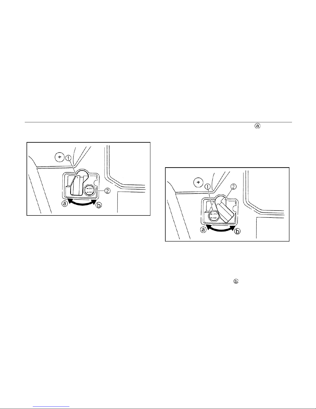
On-Command Differential Gear Lock
Switch “4WD”/”LOCK”
1. On-Command differential gear lock switch “4WD”/ “LOCK”
2. Select lever
To lock the differential gear in 4WD, stop the
vehicle, make sure the O n-Command
four-wheel-drive swit ch i s set t o “ 4WD”,
move the select lever t o , and then
On-Command four -wheel-drive switch
the select lever is set to position , and
Page 48

set the switch to “LOCK”. Whe n t he
differential gear is loc ked, t he differential
gear lock indicator light w i ll come on along
with the differential gear lock indicator in the
multifunction meter unit display .To release
the differential gear lock , stop the vehicle
and set the switch to “4WD”.
Control Functions 4-13
NOTE:
When the switch is set to “ LO CK”, the
differential gear loc k indi cator and
indicator light will flash u nt il the
differential gear is locked.
When the indicator and indicator light are
flashing, turning the steering wheel back
and forth will help the diffe r ent ial gear
lock to engage.
Riding before the differential gear lock
is properly engaged (e.g. , w hen the
HOW TO AVOID THE HAZARD
Always ride at a slow speed when the
vehicle is in 4WD-LOCK, and allow extra
time and distance for maneuvers.
WARNING
POTENTIAL HAZARD
Riding too fast while the vehicle is in
4WD-LOCK.
WHAT CAN HAPPEN
All wheels turn at the same speed when
the differential is locked, so it takes more
effort to turn the vehicle. The amount of
effort required is greater the faster you
go. You may lose control and have an
accident if you cannot make a sharp
enough turn for the speed you are
traveling.
Page 49

4-14 Control Functions
indicator and indicator light are
flashing) will cause the engine speed
to be limited until engagement is
complete.
Accelerator pedal
Press the accelerator p edal down to increase
engine speed. Spring pressure returns the
pedal to the rest position when released.
Always check that the accelerator pedal
returns normally before starting the engine.
1. Accelerator pedal
Before starting the engi ne, check the
accelerator pedal to be sure it is operating
smoothly. Make sure t he accelerator pedal
fully returns to the idle position as soon as it
is released.
Page 50

Control Functions 4-15
WARNING
1. Brake pedal
Parking brake lever
The parking brake lever is located at the right
side of the driver’s seat. It will help keep the
vehicle from moving whi le parked.
To set the parking brake, pull the lever up
POTENTIAL HAZARD
Malfunction of the accelerator pedal.
WHAT CAN HAPPEN
A faulty pedal that makes it difficul t to
speed up or slowdown could cause loss
of control.
HOW TO AVOID THE HAZARD
Check the operation of the accelerator
pedal before you start the engine .If it
does not work smoothly, check for the
cause. Correct the problem before
operating the vehicle. Consult a service
center if you cannot find or solve the
problem yourself.
Brake pedal
Press the brake pedal to slow or st op the
vehicle.
completely.
To release the parking br ake, pull up on the
lever, press the release b ut t on, and then
Page 51

4-16 Control Functions
push the lever all the way dow n. Spring
pressure helps return the lever to the
released position. Be sur e to fully release the
parking brake before start ing out, Failure to
do so may result in poor performance and
premature wearing of the rear brake and
V-belt.
1. Parking br ake lever 2. Release button
Drive select lever
The drive select lever is u s ed to shift your
vehicle into the low, high, neutral and reverse
positions. (Refer to pag es 6-4—6-6 for the
drive select lever operation.)
1. Drive select lever
Fuel tank cap
Page 52

Remove the fuel tank cap by turning it
Seats
Control Functions 4-17
counterclockwise.
1. Fuel tank cap
To remove a seat, pull its seat lock lever
upward, lift the front of the s eat , and t hen
slide the seat forward and up.
1. Driver seat 2. Passenger seat
3. Seat l ock lever (×2)
Page 53

4-18 Control Functions
To install a seat, insert t he projection on the
rear of the seat into the seat hold er s and
push down on the seat at t he front .
WARNING
POTENTIAL HAZARD
A loose seat.
WHAT CAN HAPPEN
The operator could lose control or the
operator or passenger could fall if the
seat is loose during operation.
HOW TO AVOID THE HAZARD
Make sure the seat is securely latched.
Seat belts
This vehicle is equipped with three-point seat
belts for both the operator and passenger.
Always wear the seat belt while riding in the
vehicle.
Page 54

1. Seat belt (×2) 2. Latch plate (×2)
3. Buckle (×2)
To wear the seat belt proper ly, do the
following:
1. Hold the latch plate as you pull the belt
across your lap and chest. Make sure the
belt is not twisted and is not caught on
any portion of the vehicle, your clothing,
or any equipment you are carrying.
Control Functions 4-19
2. Push the latch plate into the buckle until it
clicks. Pull up on the latch plat e t o m ake
sure it is secure.
1. Buckle 2. Latch plate
3. Put the lap portion of the belt low on your
hips. Push down on the buckle end of the
belt as you pull up on the shoulder part
so the belt is snug across your hips.
4. Position the shoulder belt over your
shoulder and across y our chest . The
Page 55

4-20 Control Functions
shoulder belt should fit against your
chest. If it is loose, pull the belt out all the
way and then let it retract.
5. To release the buckle, firmly pr ess t he
release button.
1. Buckle 2. Release button
WARNING
POTENTIAL HAZARD
Not wearing the seat belt or wearing the
seat belt improperly.
WHAT CAN HAPPEN
There is increased risk of being killed or
seriously injured in an accide n t.
HOW TO AVOID THE HAZARD
Always wear your seat belt when riding in
the vehicle.
Be sure the seat belt is close fitting
across your hips and chest and is latched
securely.
Page 56

Glove compartment
CAUTION:
To protect from damage, do not put metal
products, like tools or sh arply edged
products directly in the glove compartment. If
they must be stored, wrap them in
appropriate cushion material.
Cargo bed
Control Functions 4-21
a. Unlock b. Open.
1. Cargo bed 2. Tailgate
3. Cargo hook(×4)
Page 57

4-22 Control Functions
Opening and closing the tai lgate
1. Tailgate 2. Latch (×2)
To open
Unhook the latches, and then lower the
tailgate.
To close
Place the tailgate in the or igi nal position, and
then hook the latches.
Lifting and lowering the cargo bed
1. Cargo bed release lever
To lift
Push down cargo bed rele ase lever on left or
right side of the vehicle; sl owly lift up cargo
bed until it stops.
To lower
Lower cargo bed slowly t o it s or ig inal position
and be sure it locks into place.
Maximum load limit: 350lb ( 159kg)
Page 58

Control Functions 4-23
WARNING
POTENTIAL HAZARD
Pinch points.
WHAT CAN HAPPEN
You or someone else could be pinched
between the cargo bed and the frame
when the bed is being lowered.
HOW TO AVOID THE HAZARD
Before closing the bed, be sure others
are standing away from the vehicle. Keep
hands and fingers away from the pinch
points between the bed, frame, and OPS.
WARNING
POTENTIAL HAZARD
Overloading the cargo bed
WHAT CAN HAPPEN
Could cause changes in vehicle handling
which could lead to an accident.
HOW TO AVOID THE HAZARD
Never exceed the stated maximum load
limit for this cargo bed.
Cargo should be properly distrib uted and
securely attached.
Reduce speed when carrying cargo.
Allow greater distance for braking.
Page 59

4-24 Control Functions
WARNING
POTENTIAL HAZARD
Carrying a passenger in the cargo bed
WHAT CAN HAPPEN
The passenger could fall, be thrown out,
or be struck by objects in the cargo bed.
HOW TO AVOID THE HAZARD
Never carry a passenger in the cargo bed.
This cargo bed is designed to carry cargo
only.
Front and Rear Shock Adjustment(Option 1)
The spring preload can be adjusted to suit
the operating conditio ns.
You can reduce preload f or a softer r ide, or
increase preload if frequent bottoming out of
the UTV occurs.
CAUTION:
Frequent or severe bott oming out of the UTV
can cause increased we ar or dam age t o the
vehicle.
Adjust the spring prelo ad as follows.
To increase the spring preload, turn the
adjusting ring in directi on .
To decrease the spring preload, turn the
adjusting ring in directi on .
Page 60

Control Functions 4-25
1. Spring preload adjusting ring
2. Position indicator
NOTE:
A special wrench can be obtained at a
service center to make t hi s adju stment.
1. Special wrench
Standard position: B
A-Minimum(soft)
E-Maximum(hard)
Page 61

4-26 Control Functions
Front and Rear Shock Adjustm ent(Option 2)
WARNING
These shock absorber assemblies
contain highly pressurized nitrogen gas,
read and understand the following
information before handling the shock
absorber assemblies.
·
Do not tamper with or attempt to open
the cylinder assemblies.
·
Do not subject the shock absorber
assemblies to an open flame or other
high heat source. This may cause the unit
to explode due to excessive gas
pressure.
·
Do not deform or damage the cylinders
in any way. C ylinde r damage will result in
poor damping performance.
WARNING
POTENTIAL HAZARD
Improper shock absorber adjustment.
WHAT CAN HAPPEN
Uneven adjustment can cause poor
handling and loss of stability, which
could lead to an accident.
HOW TO AVOID THE HAZARD
Always adjust the shock absorbers o n
the left and right side to the same setting.
Page 62

Control Functions 4-27
Spring preload
The spring preload, rebound damping and
compression damping forces of the front
and rear shock absorber assemblies can be
adjusted to suit the operating conditions.
NOTE:
Never turn an adjusting mechanism beyond
the minimum and maxi mu m settings.
1. Loosen the locknut.
2. Turn the spring preload adjusting nut in
direction ⓐ to increase the spring
preload and thereby harden the
suspension, and in direction ⓑ to
decrease the spring preload and thereby
soften the suspension.
1. Locknut 2. Spring preload adjusting nut
3. Special wrench
·
Do not dispose of a damaged or worn
out shock absorber assembly yourself.
Take the shock absorber assembly to an
authorized dealer for any service.
Page 63

4-28 Control Functions
·
A special wrench can be obtained at an
authorized dealer to make this adjustment.
·
The spring preload setting is determined
by measuring distance A, shown in the
illustration. The shorter distance A is, the
lower the spring preload; the longer distance
A is, the higher the spring preload. With each
complete turn of the adjusting nut.
1. Distance A
3. Tighten the locknut.
NOTE:
Always tighten the locknut against the
adjusting nut, and then tighten it to the
specified torque.
Rebound damping force
Turn the rebound damping force adjusting
screw in direction S to increase the rebound
damping force and there by harden the
Spring travel setting(Fr ont)
Minimum(soft): 412mm(16.22 in)
Maximum(hard): 426mm(16.77 in)
Spring travel setting(Rear)
Minimum(soft): 330mm(12.99in)
Maximum(hard): 430mm(16.93 in)
Page 64

damping, and in direction F to decrease the
rebound damping force and thereby soften
the damping.
1. Rebound damping force adjusting screw
Control Functions 4-29
Compressio n damping force
Turn the compression damping force
adjusting screw (use 3.0 a lle n w r ench) in
direction ⓐ to increase the com pr ession
damping force and there by harden the
damping, and in direct ion ⓑ to decrease the
compression damping force and thereby
soften the damping.
a) C ompres si on damping force adjusting screw
Page 65

4-30 Control Functions
WARNING
·
Suspension components become hot
during operation. Never touch the
compression damping force adjusting
screw, the rebound damping force
adjusting screw or the oil reservoir with
your bare hand or skin until suspension
components have cooled.
·
Always adjust
the shock absorber
assemblies on the left and right side to
the same setting. Unev en adjustment can
cause poor handling and loss of stability,
which could lead to an accident.
Trailer hitch bracket
This vehicle is equipped with a 1 ¼ in
receiver bracket for a st andard trailer hitch.
Trailer towing equipm ent can be obtained at
a service center. (See pa ges 6-12 - 6-14 for
precaution information.)
1. Trailer hitch bracket
Page 66

Auxiliary DC jack
The auxiliary DC jack is lo cat ed at t he r ight
side of the front panel. The auxiliary DC jack
can be used for suitable wor k light s , r adi os,
etc. The auxiliary DC jack should only be
used when the engine is r unning.
Control Functions 4-31
1. Auxiliary DC jack cap
1. Set the light switch to “OFF”.
2. Start the engine. (See pages 6-1 - 6-3.)
1. Auxiliary DC jack
3. Open the auxiliary DC jack cap, and then
insert the accessory power plug into the
jack.
Maximum rated capac it y for the auxiliary
DC jack:
DC 12V, 120W (10 A)
Page 67

4-32 Control Functions
4. When the auxiliary DC jack is not being
used, cover it with the cap.
CAUTION:
Do not use accessories requir ing more
than the above maximum capacity. This
may overload the circuit and cause the
fuse to blow.
If accessories are used wit hout t he
engine running or with the headlights
turned on, the battery will lose its charge
and engine starting may become difficult.
Do not use an automotive cigarette
lighter or other accessory with a plug that
gets hot because the jack can be
damaged.
Page 68

Pre Operation Checks 5-1
Before using this vehicle, check the following items:
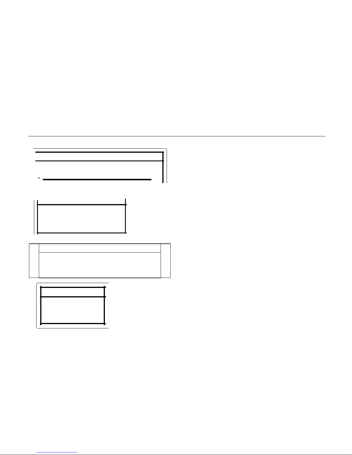
ITEM ROUTINE PAGE
Brakes
●
Check operation, free play, fluid level and fluid leakage
●
Fill with DOT 4 brake fluid if necessary
5-2 - 5-3, 8-35
Parking brake
●
Check for proper operation, condition and free play
6-8 - 6-9
Fuel
●
Check fuel level
●
Fill with fuel if necessary
5-4 - 5-5
ORS / OPS
●
Check for wear or Damage
5-10
Engine/Gear box oil
●
Check oil level
●
Fill with oil if necessary
5-5
Coolant reservoir
●
Check coolant level
●
Fill with coolant if necessary
5-6,8-21 - 8-22
Final gear oil /
Differential gear oil
● Check for leakage
5-7
Accelerator pedal
●
Check for proper accelerator pedal operation
5-8
Seat belts
●
Check for proper operation and belt wear
5-10
Steering
●
Check for proper operation
5-10
Fittings and fas teners
●
Check all fittings and fasteners
5-11
Lights and switches
●
Check for proper operation
5-11
Wheels and tires
●
Check tire pressure, wear and damage
5-11 - 5-13,8-41- 8-42
Axle boots
●
Check for damage
8-23
Instrument
●
Check for complete and correct display
4-2 - 4-8
Light/Indicator
●
Check for light / indicator operation
4-2 - 4-8
Page 69

5-2 Pre Operation Checks
Brakes
Check for correct brake pedal free play. If the
brake pedal free play is incorrect, have a
service center adjust it. (See pages 8-37 8-38.)
Check the operation of the brake pedal. It
should move smoothly and there should be a
firm feeling when the brakes are applied. If not,
have the vehicle inspected by a service center.
Brake fluid level
Check the brake fluid level. Add fluid if
necessary. (See pages 8-34)
Recommended bra ke fl ui d: DOT 4
WARNING
POTENTIAL HAZARD
Failure to inspect the vehicle before
operati ng. Fa il ure to properly maintain the
vehicle.
WHAT CAN HAPPEN
Increases the possibility of an accident or
equipment damage.
HOW TO AVOID THE HAZARD
Always inspect your vehicle each time you
use it to make sure the vehicle is in safe
operating condition. Always follow the
inspection and maintenance proce dure s
and schedules described in the Owner’s
Manual.
Page 70

Pre Operation Checks 5-3
Brake fluid leakage
Check to see if any brake fluid is leaking out of
the hydraulic brake lines, fittings, or the brake
fluid reservoir. Apply the brakes fir mly for one
minute. If there is any leakage, have the vehicle
inspected by a service center.
Brake operation
Test the brakes at slow speed after starting out
to make sure they are working properly. If the
brakes do not provide proper braking
performance, inspect the brake system. (See
pages 8-33 - 8-37.)
WARNING
POTENTIAL HAZARD
Driving with impro perly opera ting br akes .
WHAT CAN HAPPEN
You could l ose braking ability which could
lead to an accident.
HOW TO AVOID THE HAZARD
Always check the brakes at the start of
every ride. Do not operate the vehicle if you
find any problem with the brakes. If a
problem cannot be corrected by the
adjustme nt pro ced ures pr ovide d in this
manual, have the vehicle inspected by a
service center.
Page 71

5-4 Pre Operation Checks
Fuel
Make sur e ther e is sufficient gasoline in the
tank.
Use only unleaded gasoline. The use of leaded
gasoline will cause severe damage to internal
engine parts, such as the valves and piston
rings, as well as to the exhaust system.
Your engine has been designed to use regular
unleaded gasoline with a pump octane number
([R+M] /2) of 91 or higher, or research octane
number of 91 or higher. If knocking or pinging
occurs, use a different brand of gasoline or
premium unleaded fuel. Unleaded fuel will give
you longer spark plug life and reduced
maintenance cost.
Gasohol
The UTV uses an electric fuel injection system,
and its emissions meet the requirements of the
US Environment Protection Agency. Never use
E-85 fuel or any fuel containing great er than
E-10 Ethanol. Fuels cont aining greater than
E-10 Ethanol will damage the engine and void
any warranties.
Recommended fuel:
Unleaded Non Ethanol 91 Octane or
higher gasoline only. E-10 Max Fuel
Fuel tank capacity:
7.7 gal (29L)
CAUTION:
Page 72

Pre Operation Checks 5-5
Engine oil
Make sure the engine oil is at the specified level.
Add oil as necessary. (See pages 8-12)
CAUTION:
In order to prevent clutch slippage
(since the engine oil also lubricates the
clutch), do not mix any chemical
additives. Do not use oils with a diesel
specification of “CD” or oils of a
higher quality than specified. In addition,
do not use oils labeled
“ENERGYCONSERVING II” or
higher.
Make sure that no foreign material
enters the crankcase.
WARNING
POTENTIAL HAZARD
Improper care when refueling.
WHAT CAN HAPPEN
Fuel can spill, which can cause a fire and
severe injury. Fuel expands when it heats
up. If the fuel tank is overfilled, fuel could
spill out due to heat from the engine or the
sun.
HOW TO AVOID THE HAZARD
Do not overfill the fuel tank. Be careful not
to spill fuel, especially on the engine or
exhaust pipe. Wipe up any spilled fuel
immediately. Be sure the fuel tank cap is
closed securely.
Page 73

5-6 Pre Operation Checks
Recommended engine oil type and
quantity:
See page 11-2
CAUTION:
Hard water or salt water is harmful to the
engine.
You may use soft water if you cannot get
distilled water.
Coolant
Check the coolant level in the coolant reservoir
when the engine is cold. (The coolant level will
vary with engine temperature.) The coolant
level is satisfactory if it is between the minimum
and maximum level marks on the coolant
reservoir. If the coolant level is at or below the
minimum level mark, add additional coolant to
bring the level up to maximum level mark. If
coolant is not available, add distilled water.
Change the coolant every two years. (See
pages 8-21 - 8-22 for details)
Coolant reservoir cap acity
(up to the maximum level mark):
0.37 qt, (0.35L)
Page 74

Pre Operation Checks 5-7
WARNING
Final gear oil
Make sure the final gear oil is at the specified
level. Add oil as necessary. (See pages 8-17 8-18 for details)
Recommended oil:
SAE 80 API GL -4 Hy poid gear oil
If desired, an SAE 80W90 hypoid gear oil may
be used for all conditions.
NOTE:
GL-4 is a quality and additive rating, GL-5 or
GL-6 rated hypoid gear oils may also be used.
Differential gear oil
POTENTIAL HAZARD
Removing the radiator cap when the engine
and radiator are still hot.
WHAT CAN HAPPEN
You could be burned by hot fluid and steam
blown out under pressure.
HOW TO AVOID THE HAZARD
Wait for the engine to cool befor e removing
the radiator cap. Always use a
thick rag over
the cap. Allow any remaining pressure to
escape before completely removing the cap.
Make sure the differential gear oil is at the
specified level. Add oil as necessary. (See
pages 8-19 - 8-20 for details.)
Page 75

5-8 Pre Operation Checks
WARNING
Failure to check or maintain proper
operation of the throttle system can result in
an accident and lead to serious injury or
death if the throttle pedal sticks during
operation.
Never st art or operate this vehicle if it has a
sticking or improperly oper ating throttle
pedal.
Immediately contact your service center for
service if throttle problems arise.
Always check the pedal for free movement
and return before starting the engine and
occasionally during operation.
Throttle Pe dal
Check to see that the accelerator pedal
operates correctly. It must operate smoothly
and fully spring back to the idle position when
released. Have a service center repair as
necessary for proper operation.
Throttle Freeplay
If the throttle pedal has excessive play due to
cable stretch or mis-adjustment, it will cause a
delay in t hrottle response, especially at low
engine speed. The throttle may also not open
fully. If the throttle pedal has no freeplay, the
throttle may be hard to control, and the idle
speed may be erratic. Check the throttle pedal
freeplay. Adjust the freeplay if necessary.
Recommended oil:
SAE 80 API GL -5 Hy poid gear oil
Page 76

Pre Operation Checks 5-9
Throttle Freeplay Adjust m e nt
1. Remove both seats. Remove the middle
cover of the engine. (see PAGE 8-9 )
2. Loosen the nut of throttle cable on the
valve,
3. Spin the throttle cable inside (A)/ outside (B)
to increase the thrott le pedal’s moving
distance to 1/16 to 1/ 8 inches (1.5-3mm).
1.Accele rator Cable column nut
4. Tighten the the nut.
5. Reinstall the center cover and seats to their
correct and locked positions.
Steering Wheel Ins pection
Check the steering wheel for specified freeplay
and smooth operation.
1. Position the vehicle on level ground.
Throttle Freeplay Inspec t ion
1. Set the parking brake .
2. Apply the brakes. Start the engine. Allow it
to warm up thoroughly.
3. Measure the distance the throttle pedal
moves before the engine begins to pick up
speed. Freeplay should be 1/16 t o 1/8
inches (1.5-3mm).
Page 77

5-10 Pre Operation Checks
2. Lightly turn the steering wheel left and right.
3. There should be 0.8″-1.0″ (20-25 mm)
of freeplay.
If there is excessive freeplay, unusual noises, or
the steering feels rough or″catchy, ″have the
steering system inspected by an authorized
service center。
Seat belts
Make sur e that b oth seat belts are not frayed or
damaged. The seat belt must move smoothly
when pulled out and retract on its own when
released. The latch plate should click securely
into the buckle and release when the release
button is pushed firmly. Wash off any dirt or
mud which could affect operation. Have a
service center repair as necessary for proper
operation. Also check any netting in the ORS
system and the OPS stru cture for integrity.
Fittings and fas teners
Always check the tightness of chassis fittings
and fasteners before a ride. Take the vehicle to
a service center or refer to the Service Manual
for correct tightening torque.
Lights
Check the headlights and t ail/brake lights to
make sure they are in working condition. Re pair
as necessary for proper operation.
Switches
Check the operation of all switches. Have a
service center repair as necessary for proper
operation.
Page 78

POTENTIAL HAZARD
Operating this vehicle with improper tires,
or with improper or uneven tire pressure.
WHAT CAN HAPPEN
Use of improper tires on this vehicle, or
operation of this vehicle with improper or
uneven tire pressure, may cause loss of
control, i ncre as ing y our risk of accident.
HOW TO AVOID THE HAZARD
1. The tires listed below have be en
approved by Manufacturer for this
model. Other tire combinations are not
recommended.
2.
Pre Operation Checks 5-11
Tires
Type
Size
Front
26×8-12
6PR
Rear
26×10-12
6PR
WARNING
3.
The tires should be set to the
recommended pressure:
Front 10psi (70kpa, 0.7 kgf/cm
2
)
Rear 10psi (70kpa, 0.7 kgf/cm
2
)
Check and adjust tire pressures when the
tires are cold. Tire pressures must be
equal on both sides.
4.
Tire pressure below the minimum
specified could cause the tire to dislodge
from the r im under severe ridin g
conditions. The following are minimums:
Front 10psi (63 kpa, 0.64kgf/cm
2
)
Rear 10psi (63 kpa, 0.64kgf /cm
2
)
Page 79

5-12 Pre Operation Checks
Set pressure with tires cold. Set tire pressures
to the fol lowing specificatio ns:
Recommended
Pressure
Minimum Maximum
Front
10psi (70kpa
(0.70kgf/ cm2)
9 psi (63kpa,
0.64kgf/ cm2)
11 psi, (77kpa,
0.77kgf/
cm2)
Rear
10psi (70kpa
(0.70kgf/ cm2)
9 psi (63kpa,
0.64kgf/ cm2)
11 psi, (77kpa,
0.77kgf/ cm2)
How to measure tire pressure
Use the tire pressure gau ge.
NOTE:
The tire pressur e gauge is included as standard
equipment. Make two measurements of the tire
pressure an d use the s econd reading. Dust or
dirt in the gauge could cause the first reading to
be incorrect.
1. Tire pressure gauge
5. Use no more tha n the foll owing pr essur es
when seating the tire beads.
Front 36psi ( 250kpa, 2.5kgf/cm
2
)
Rear 36psi (250kpa, 2.5kgf/cm
2
)
Higher pressures may cause the tire to burst.
Inflate the tires very slowly and carefully. Fast
inflati on coul d cause the tire to burst.
Page 80

Pre Operation Checks 5-13
Tire wear limit
When the tir e groov e decreases to 0.12 in (3
mm) due to wear, replace the tire.
a. Tire wear limit
Page 81

6-1 Operation
Starting the engine in low
temperatures
1. Check the throttle cable, parking brake,
and the reverse lock out c abl e, and make
sure that they are not frozen.
2. Start the engine ( see P6-2).
WARNING
POTENTIAL HAZARD
Freezing control cables due to cold
weather conditions.
WHAT CAN HAPPEN
Loss of vehicle control, which coul d
lead to an accident or collision .
HOW TO AVOID THE HAZARD
When riding in cold weather, always
make sure all control cables work
smoothly before you begin riding.
WARNING
POTENTIAL HAZARD
Operating vehicle without being fam iliar
with all controls.
WHAT CAN HAPPEN
Loss of control, which could cause an
accident or injury.
HOW TO AVOID THE HAZARD
Read the Owner’s Manual carefully. If
there is a control or function y o u d o n ot
understand, ask your service center.
Page 82

Starting the Engine
See the “Engine Brea k-In”sectio n pr ior t o
operating the engine for the first time.
1. Turning the key to “ON”, the light in the
display will turn on, and el ectronic
injection system’s fue l pump will start to
work; wait for 10 second before the
following operation.
2. Apply the brake.
3. Shift the drive select lever into the neutral
position.
NOTE:
● When the drive select lever is in the
neutral position“N”, the neutral indicator
light should come on. If the neutral
Operation 6-2
indicator light does not come on, ask a
service center to inspect the electric
circuit.
● The engine can be started in any gear i f
the brake is applied. However, it is
recommended to shift into neutral ”N”
before starting the engine.
4. With your foot off the acceler at or pedal,
start the engine by tur ning t he key t o
“START”.
NOTE:
If the engine fails to start, r elea se the key,
and then try starting aga in . Wait a few
seconds before the next attempt. Each
cranking should be as sho r t as possible to
preserve battery ener gy. Do not crank the
engine more than 5 seconds on each
CAUTION:
Page 83

6-3 Operation
attempt.
5. Continue warming up the engine until it
idles smoothly before riding.
WARNING
POTENTIAL HAZARD
Engine idle speed exceeds the regulated
speed.
WHAT CAN HAPPEN
Will make it difficult to select the proper
gear, which could lead to loss of control,
causing serious injury or even death.
HOW TO AVOID THE HAZARD
Because of electronic injection system, the
idle speed will speed up when the voltag e
of battery is low.
Place the gear on position ‘N’, and press
Warming Up
To get maximum engine li fe, alw ays warm up
the engine before drivin g. Never accelerate
hard with a cold engine! To see whether or
not the engine is warm, check if it responds
to the throttle normally .
1. Release the brakes and press the
accelerator pedal gradually.
2. If the speed of the e ngine accelerates with
pedal steadily, the engine is warm and
the vehicle can been ridde n. Otherwise,
the throttle pedal to make the engine run at
2500RPM to charge the battery for 5-10
minutes; when the voltage of battery is over
12V, the idle speed will be normal. If the
idle speed is still high, please contact your
service center.
Page 84

go on with the third step.
3. Continue warming up the engine until it
idles smoothly.
See the “Engine break-in” section prior to
operating the engine for the first time.
Drive Select Lever Operation and
Driving In Reverse
CAUTION:
Before shifting, y ou must stop the UTV and
return the throttle lever to the closed position;
otherwise the trans mission may be
damaged.
Operation 6-4
Shifting: Neutral to High and High to Low
1. Stop the vehicle. Keep your foot off the
accelerator pedal.
2. Apply the brakes, and t hen shift by
moving the drive select l ever along the
shift guide.
NOTE:
Make sure that the driv e select lever is
completely shifted into position.
CAUTION:
Page 85

6-5 Operation
1. Drive select lever
3. Release the brakes and pr ess t he
accelerator pedal gradually.
Shifting: Neutral to Reverse
1. Stop the vehicle. Keep your foot off the
accelerator pedal.
2. Apply the brake pedal.
3. Shift from neutral to reverse or vice versa
by moving the drive select lever along
the shift guide.
NOTE:
● Always depress the brake pedal before placing
the gearshift lever to“reverse”position.
● In the brake pedal, there is a cable, which is
connected to a position pin located on the
gearshift assembly. Only when the brake pedal
is depressed, the position pin will be retracked,
and gearshifts can be removed to “reverse”
position.
1. Position pin 2.Cable 3. Adjust
Page 86

1. Drive select lever
NOTE:
● When in reverse, the reverse indicator
light should be on. If the li ght does not
come on, ask a service center to inspect
the reverse indicator lig ht electrical
circuit.
● Due to the synchronizing mecha nis m in
Operation 6-6
the engine, the light may not c ome on
until the vehicle starts moving.
4. Check behind for people o r obst ac l es,
and then release the brake pedal.
5. Press the accelerator p edal gradually
and continue to watch to the rear while
backing up.
Page 87

6-7 Operation
WARNING
POTENTIAL HAZARD
Parking on a hill or other incline.
WHAT CAN HAPPEN
The vehicle could roll out of control,
increasing the chance of an accident.
HOW TO AVOID THE HAZARD
Avoid parking on hills or other inclines. If
you must park on an incline, apply the
parking brake, and block the front and
rear wheels with rocks or other obj ects.
Never park the vehicle on hills that are
too steep.
WARNING
POTENTIAL HAZARD
Improperly operating in reverse.
WHAT CAN HAPPEN
You could hit an obstacle or person
behind you, resulting in serious injury.
HOW TO AVOID THE HAZARD
When you shift into reverse, make sure
there are no obstacles or people behind
you. When it is safe to proceed, go
slowly.
Page 88

Parking
a) When parking, stop the engine and shift
the drive select lever into t he neut r al
position.
b) Push the brake pedal down, and pull the
parking brake to top position to park the
vehicle
Parking on a Slope
Operation 6-8
1.Parking handbar
1. Bring the vehicle to a stop by applying
the brakes.
2. Stop the engine.
3. With the brakes applied, set the parking
brake.
Page 89

6-9 Operation
1.parking handbar
NOTE:
Like many other vehicles, the parking brake
acts on the rear wheels. F or t he parking
brake to operate all four w heels, shift to 4WD
before stopping the eng in e.
Vehicle Break-in Period
The break-in period for your new UTV
vehicle is the first 25 hours of operation, or
the time it takes to use the first three tanks
full of gasoline. No single action on your part
is as important as a proper break-in period.
Careful treatment of a new engine and drive
components will result i n more efficient
performance and longer l if e for t hese
components. Perfor m the following
procedures carefully.
CAUTION:
● Excessive heat build-up dur ing t he first
three hours of operation will damage
close-fitted engine parts and drive
components. Do not op er at e at ful l throttle
or high speeds during the first t hr ee hours
Page 90

of use.
● Use of any engine oil not mentioned in
this manual will cause severe dama ge to
the engine.
Engine Break-In
There is never a more important period in the
life of your vehicle than the period between 0
and 25 hours. For this rea son, we ask that
you carefully read the fo ll owing material.
Because the engine is brand new, you must
not put an excessive load on it for t he first
several hours of running.
During the first 25 hours, t he various parts in
the engine wear and polish themselves to the
correct operating cle ar ances. During this
period, prolonged ful l thr ot t le operation or
any condition which might result in excessive
engine heating must be a voided. However,
Operation 6-10
momentary (2-3 seconds maximum) full
throttle operation under load does not harm
the engine.
Each full throttle acceleration sequence
should be followed with a subs t antial rest
period for the engine by cr uis ing at l ow er
engine speed so the engi ne can r id itself of
the temporary build up of heat. If any
abnormality is notice d during this period,
consult a service center.
0-10 Hours:
Avoid continuous operation above half
throttle. Allow a cooling off period of five to
ten minutes after every hour of operation.
Vary the speed of the vehic le from time to
time. Do not operate it at one set t hr ottle
position.
Page 91

6-11 Operation
10-25 Hours:
Avoid prolonged operation above 3/4 throttle.
Rev the vehicle freely but do not use full
throttle at any time.
After break-in:
The vehicle can now be o per at ed normally.
Brake System Break-in
Apply only moderate bra king force for the
first 50 stops. Aggress iv e or overly forceful
braking when the brake system is new could
damage brake pads and rotors.
CVT Break-in (Clutches/Belt)
A proper break-in of the cl ut ches and drive
belt will ensure a longer lif e and bet ter
performance. Break in t he clutches and belt
by operating at slower sp eeds during the
break-in period as reco m me nded. Pull only
light loads. Avoid aggre ss i ve acceleration
and high speed operation during the break-in
period.
Accessories
Accessories can affect the handling and
control of your vehicle. Keep the following in
mind when considering an accessory or
operating a vehicle that h as accessories.
● Choose only accessories designe d for
your vehicle. Your service center has a
variety of genuine accessories. Other
accessories may also be available on the
market. It is not possible to test all
Page 92

nonstandard accessories, nor have any
control over the qual ity or suitability of
them. Choose only genu ine accessories,
or accessories which are equivalent in
design and quality.
● Accessories should be rigidly and
securely mounted. An accessory that can
shift position or come of f w hile you are
operating could affect your ability to
control the vehicle.
● Do not mount an accessory w her e it
could interfere with y our abil ity to control
the vehicle. Examples in c l ude ( but ar e
not limited to) an object t hat limits your
ability to turn the steering wheel or one
that limits your view.
● Use extra caution when driving a vehicle
Operation 6-12
with accessories. The vehicle may
handle differently than it does without
accessories.
Loading
Cargo or a trailer can change the stability
and handling of a vehicle. Y ou mu s t use
common sense and good judgment when
carrying cargo or towing a trailer. Keep the
following points in mind:
● Never exceed the weight limits sh own
below. An overloaded v ehicle can be
unstable.
● Choose a trailer hitch drawbar designed
for use with a 1 ¼ in receiver.(See page
4-31 for more information)
● Do not exceed the maximum tongue
Page 93

6-13 Operation
weight. You can measur e tongue weight
with a bathroom scale. Put the tongue of
the loaded trailer on the scale with the
tongue at hitch height. A dj ust the load in
the trailer, if necessar y, to reduce the
weight on hitch. If you are carrying cargo
and towing a trailer, include the tongue
weight in the maximum v ehicle load limit.
MAXIMUM LOADING LIMIT
● Vehicle loading limit (total weight of
cargo, operator, passe nger and
accessories, and tongue weight):
880 lb (399Kg)
● Cargo bed:350 lb (159Kg)
● Trailer hitch:
Pulling load (total weight of trailer
and cargo): 1,212lbf (550Kgf)
Tongue weight (vert ical weight on
trailer hitch point): 110 lbf (50Kgf)
● Load cargo in the cargo bed as close t o
the center of the vehicle a s possible and
tie it down using the cargo hooks
equipped on the cargo bed.
● Tie down cargo securely in the t r ailer.
Make sure cargo in the trailer cannot
Page 94

move around. A shifting load can cause
an accident.
● Make sure the load does not interfere
with controls or your ability to see where
you are going.
● Drive more slowly than you would without
a load. The more weight y ou car r y, the
slower you should go. Alt hough
conditions vary, it is good pract ice not to
exceed low range whenever you are
carrying heavier loads or when towing a
trailer.
● Allow more braking distance. A heav ier
vehicle takes longer t o stop.
● Avoid making sharp turns unless at v er y
slow speeds.
● Avoid hills and rough terrain. Choose
Operation 6-14
terrain carefully. Added weight affects the
stability and handling of the vehicle.
Page 95

6-15 Operation
WARNING
POTENTIAL HAZARD
Overloading this vehicle or c ar ry ing or
towing cargo improperly.
WHAT CAN HAPPEN
Could cause changes in vehicle handling
which could lead to an accident.
HOW TO AVOID THE HAZARD
Never exceed the stated load capacity for
this vehicle.
Cargo should be properly distrib uted and
securely attached.
Reduce speed when carrying cargo or
pulling a trailer. Allow greater distance
for braking.
Page 96
Your Vehicle 7-1
DRIVING YOUR VEHICLE
GETTING TO KNOW YOUR VEHICLE
This off-highway ut ility vehicle will handle
and maneuver differently form an ordinary
passenger car or other vehicle.
Before you begin to use your vehicle, be sure
you have read this Owner’
s Manual
completely and under st and all the features.
Pay particular attenti on t o t he safety
information on pages 2-1 - 2-18. Please read
all the caution and warning labels on your
vehicle.
This vehicle is designed f or t he oper at or and
one passenger. The driv er and passenger
must always wear a seat belt. Never carry
passengers in the cargo bed.
WARNING
POTENTIAL HAZARD
Not wearing the seat belt.
Wearing the seat belt improperly.
WHAT CAN HAPPEN
There is increased risk of being killed or
seriously injured in an accide n t.
HOW TO AVOID THE HAZARD
Always wear your seat belt when riding in
the vehicle.
Be sure the seat belt is close fitting
across your hips and chest and is latched
securely.
Page 97

7-2 Your Vehicle
The total weight of operator, passenger,
accessories, cargo, tr ai ler tongue weight,
and the vehicle itself must not exceed 1,880
lbs (853Kg).
WARNING
POTENTIAL HAZARD
Carrying a passenger in the cargo bed .
WHAT CAN HAPPEN
The passenger could fall or be struck by
objects in the cargo bed.
HOW TO AVOID THE HAZARD
Never carry a passenger in the cargo bed.
The cargo bed is designed to carry cargo
only.
Page 98

Your Vehicle 7-3
The driver and passenger must always wear
a seat belt, an approved motorcycle helmet,
eye protection and protective clothing,
including over-the-ankle b oot s, gloves, a
long-sleeved shirt or jacket, and long pants.
Keep hands and feet ins id e t he vehicle at all
times.
WARNING
POTENTIAL HAZARD
Overloading this vehicle or c ar rying or
towing carg o improperly.
WHAT CAN HAPPEN
Could cause changes in vehicle
handling which could lead to an
accident.
HOW TO AVOID THE HA ZARD
Never exceed the state d load capacity
for this vehicle.
Cargo should be properly distributed
and securely at t ached.
Reduce speed when carrying cargo or
pulling a trailer. Allow greater distance
for braking.
Always fol low the instructions i n your
Owner’s Manual for carr ying cargo or
pulling a trailer.
Page 99

7-4 Your Vehicle
WARNING
POTENTIAL HAZARD
Operating this vehicle without wearing an
approved motorcycle helmet, eye
protection, and protective clothing.
WHAT CAN
HAPPEN
Operating without
an approved
motorcycle helmet
increases your
chances of a severe
head injury or death
in the event of an
accident.
Operating without eye protection can
result in an accident and increases your
chances of a severe injury in the event of
an accident.
HOW TO AVOID THE HAZARD
Always wear an approved motorcycle
helmet that fits properly. You should al so
wear:
eye protection (goggles
or face shield) gloves
boots
long-sleeved shirt or jacket
long pants
Page 100

Your Vehicle 7-5
LEARNING T O OPERATE YOUR VEHICLE
You should become fam il i ar w it h t he
performance charact er istics of the vehicle in
a large, flat area that is free of ob stacles and
other vehicles. Pract ice control of the
accelerator pedal, brakes, steering, and drive
select lever. Drive at a slo w speed and
become comfortable at that speed before
gradually increasing your speed. Become
familiar with the way t he vehicle feels in low
and high ranges, first in two-wheel drive
(2WD) and then in four-w heel drive (4WD)
and four-wheel drive with the differential
locked. Practice driv ing i n reverse. Take the
time to learn basic operat i on before
attempting maneuvers that are more difficult.
Perform the Pre-Operat ion Checks on pages
5-1 - 5-11. Set the parking brake, shift to
neutral, and follow the in st r uct ions on page
6-1 to start the engine. Once it has w armed
up you are ready to begin driving your
vehicle. With the engine i dling, shift the drive
select lever into low or hig h. Then r elease the
parking brake. Press th e accelerator pedal
slowly and smoothly . The cent r i fugal clutch
will engage and you will st art to accelerate.
Avoid higher speeds until you are thoroughly
familiar with the operati on of your vehicle.
When slowing down or stopping, take your
foot off the accelerator pedal and smoothly
press the brake pedal. Improper use of the
brakes can cause the tires to lose traction,
reducing control and incr easing the
 Loading...