

Page 1
Safe Operation Practices • Set-Up • Operation • Service • Troubleshooting
OperatOr’s Manual
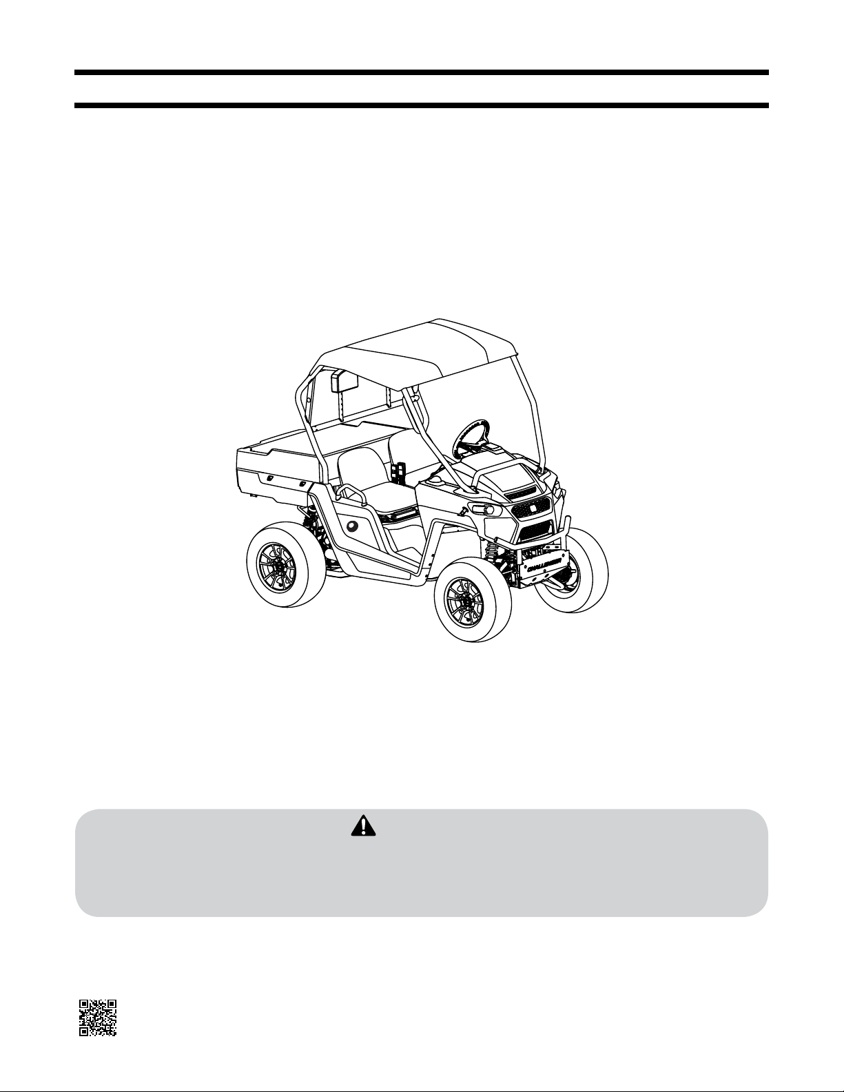
Utility Vehicle
Challenger 4 x 4
Table of Contents
Important Safe Operation Practices ..................... 2
Introduction ............................................................. 6
Set-Up ....................................................................... 7
Controls & Operation .............................................. 8
WARNING
READ AND FOLLOW ALL SAFETY RULES AND INSTRUCTIONS IN THIS MANUAL
BEFORE ATTEMPTING TO OPERATE THIS MACHINE.
FAILURE TO COMPLY WITH THESE INSTRUCTIONS MAY RESULT IN PERSONAL INJURY.
NOTE: This Operator’s Manual co vers several models. Features may vary by model. Not all features in this manual are applicable to all
models and the model depicted may differ from yours.
Product Care ...........................................................13
Specications ..........................................................21
Warranties ............................................................. 26
Form No. 769-12553
(November 2, 2017)
Page 2

Introduction
2
Thank You
Thank you for purchasing a Cub Cadet Utility Vehicle. It was carefully engineered
to provide excellent performance when properly operated and maintained.
Please read this entire manual prior to operating the vehicle. It instructs you how
to safely and easily set up, operate and maintain your vehicle. Please be sure
that you, and any other persons who will operate the vehicle, carefully follow
the recommended safety practices at all times. Failure to do so could result in
personal injury or property damage.
All information in this manual is relative to the most recent product information
available at the time of printing. Review this manual frequently to familiarize
yourself with the vehicle, its features and operation. Please be aware that this
Operator’s Manual may cover a range of product specifications for various
models. Characteristics and features discussed and/or illustrated in this manual
may not be applicable to all models. We reserve the right to change product
specifications, designs and equipment without notice and without incurring
obligation.
If applicable, the power testing information used to establish the power rating of
the engine equipped on this vehicle can be found at www.opei.org or the engine
manufacturer’s web site.
If you have any problems or questions concerning the vehicle, phone your
local Cub Cadet dealer or contact us directly. Cub Cadet’s Customer Support
telephone numbers, website address and mailing address can be found on this
page. We want to ensure your complete satisfaction at all times.
Throughout this manual, all references to right and left side of the machine are
observed from the operating position.
Product Registration and Customer Support
Please do NOT return the machine to the retailer or dealer without first contacting the Customer Support Department
Please register your product on our website, www.cubcadet.com.
If you have difficulty assembling this product, have questions regarding the controls, operation, or maintenance of this machine, want to order
replacement parts/attachments/accessories, or want to view an online How-To video; you can seek help from the experts. Have your full model number
and serial number ready. Choose from the options below:
◊ Web: www.cubcadet.com/equipment/cubcadet/service-and-parts
◊ Phone: (800) 965-4CUB
◊ Mail: Cub Cadet LLC • P.O. Box 361131 • Cleveland, OH • 44136-0019
Record Product Information
Before setting up and operating your new vehicle, please locate
the model plate on the vehicle and record the information in the
provided area to the right. You can locate the model plate under
the operator’s seat. Flip the seat forward to view the model plate.
This information will be necessary, should you seek technical
support via our web site or with your local Cub Cadet dealer.
P
RODUCTIDENTIFICATION NUMBER
MODEL NUMBER
SERIAL NUMBER
2
Page 3

Important Safe Operation Practices 2
WARNING
This symbol points out important safety instructions which, if not followed, could endanger the personal safety and/or property of yourself and others. Read and follow all instructions in this
manual before attempting to operate this machine. Failure to comply with these instructions may result in personal injury. When you see this symbol. HEED ITS WARNING!
WARNING
California Proposition 65
Engine Exhaust, some of its constituents, and certain vehicle components contain or emit chemicals known to State of California to cause cancer and birth defects or other reproductive harm.
Batter y posts, term inals, and rela ted accessorie s contain lead an d lead compound s, chemicals k nown to the State of Ca lifornia to cau se cancer and re productiv e harm. Wash hands af ter
handling.
DANGER
This mac hine was built to be o perated accor ding to the safe op eration prac tices in this man ual. As with any ty pe of power equip ment, carele ssness or error o n the part of the o perator can
result in serious injury. This machine is capable of amputating hands and feet and throwing objects. Failure to observe the following safety instructions could result in serious injury or death.
Operation
General Operation
1. Read, understand, and follow all
instructions on the vehicle and in the
manual before attempting to operate
or service vehicle. Keep this manual
in a safe place for future and regular
reference and for ordering replacement
parts.
2. This is an off-road utility vehicle and
it should not be operated on public
highways. Know and comply with all
laws and regulations governing the use
of off-highway vehicles in your area.
3. This vehicle handles and maneuvers
differently than a normal passenger
car. Sharp high speed turns and abrupt
maneuvers can cause vehicle to roll over
or go out of control. Slow down when
turning and avoid abrupt maneuvers.
4. Handling and maneuvering
characteristics of vehicle change
depending upon cargo load. Heavy
loads affect steering, braking, stability,
and overall handling of vehicle.
5. Be familiar with all instructions and
controls and their proper operation
before starting vehicle.
6. Never allow adults to operate this
vehicle without proper instruction.
7. Never allow children under 16 years
old to operate this vehicle. Children
16 years old and over should read and
understand the operation instructions
and safety rules in this manual and
should be trained and supervised by a
parent.
8. Watch for traffic when operating near
or crossing roadways. This vehicle is not
intended for use on any public roadway.
9. Do not operate this vehicle while under
the influence of alcohol or drugs.
10. Never carry more than one passenger.
This vehicle is designed to carry the
driver and one passenger only. No riders
are allowed in cargo box or anywhere
else on vehicle, except in the driver and
passenger seats.
11. Keep all body parts (i.e. head, arms,
hands, legs, feet) inside vehicle when
vehicle is in motion.
12. Always remain seated and keep both
hands on the steering wheel when
driving the vehicle.
13. Sit on the center of the seat and keep
both feet within the foot platform
perimeter. Clean foot platform if dirty
and remove any debris from around foot
controls, e.g. brake pedal.
14. Do not misuse the utility vehicle. It is an
utility vehicle, not a recreation vehicle
or toy. Recreational riding can lead to
accidents, severe bodily injury or death.
15. Inspect area around vehicle before
moving, especially in reverse. Back up
slowly. Always look down and behind
before and while backing to avoid a backover accident. Keep bystanders out of area.
16. Avoid driving through water, since loss
of control may occur. Drive belt may
slip if exposed to water thus reducing
vehicle pulling power and stopping
vehicle entirely.
17. Always use vehicle lights while operating in
low light situations.
18. Do not mount or leave vehicle while it is
in motion or in actual operation.
19. Avoid sudden starts, stops, or turns and
always use a level turn-around area.
20. Never leave vehicle unattended with the
key in the ignition. Always turn key to
the STOP position, make sure the vehicle
is in the PARK position and remove key.
21. Check overhead clearances carefully
before driving under low hanging tree
branches, wires, power lines, bridges,
before entering or leaving buildings, or
in any other situation where the operator
and/or operator protective structure
(OPS) may be struck, which could result in
serious injury.
22. Use the operator protective structure
(OPS) and seat belt for safe operation.
Overturning the utility vehicle without
a operator protective structure (OPS),
or with a operator protective structure
(OPS) and the seat belt unfastened, can
result in death or injury.
23. Always use the seat belt, except if the
operator protective structure (OPS) has
been removed.
24. Improper use of the vehicle or failure
to properly maintain it could result
in decreased vehicle performance or
personal injury.
25. Engine must be stopped when cleaning,
servicing, adjusting, repairing, or
installing attachments on utility vehicle.
26. After striking foreign objects, stop the
unit and shut off the engine. Inspect for
damage and repair the damage before
restarting and operating equipment.
27. Do not start or operate vehicle in an
inside area, unless it is adequately
ventilated. Engine exhaust contains
carbon monoxide fumes, which are very
poisonous and can be deadly.
28. Do not change engine governor setting
or over speed the engine. The governor
is set at the factory for safe operating
speed.
29. Assure safety interlock switch is adjusted
correctly so engine cannot be started
unless gearshift is in the neutral position
with the brake engaged or the PARK
position.
30. Do not touch engine or muffler while
engine is running or soon after it is
stopped. They will be hot and can cause
a burn.
31. Always inspect your vehicle each time
you use it to make sure it is in safe
operating condition. Always follow the
inspection and maintenance procedures
and schedules described in this manual.
32. If situations occur which are not covered
in this manual, use care and good
judgement. Contact your local service
center or call toll free 1-877-282-8684 for
the name of your nearest service center.
3
Page 4

Slope Operation
Slopes are a major factor related to loss of
control and rollover accidents, which can result
in severe injury or death. If a slope is steeper
than a 15° incline, do not operate this unit
on that area. Exercise extreme caution while
operating on slopes.
Do:
1. Travel straight up and down slopes, not
across. Exercise extreme caution when
changing direction on slopes.
2. Travel slowly while on a slope. Always
keep the forward speed limited when
going down slopes to take advantage of
the motor braking action.
3. Keep all movement on the slopes slow
and gradual. Avoid starting or stopping
on a slope.
4. Avoid slopes with slippery, loose, or
bumpy surfaces as they are especially
hazardous.
5. Use extra care while carrying cargo. It
may affect the stability of the vehicle.
Spread the load evenly or tie down.
Do Not:
1. Do not travel near drop-offs, ditches
or embankments. The vehicle could
suddenly turn over if a wheel is over the
edge of a cliff, ditch, or if an edge caves
in.
2. Do not stop or start suddenly when
going uphill or downhill. Be especially
cautious when changing direction on
slopes.
3. Do not turn sideways to the hill. The
vehicle may roll over. If you must turn, go
slow and do so carefully and gradually.
4. Do not carry cargo on steep slopes or
tow loads.
Tow ing
1. Always use an approved hitch and hitch
point provided on the utility vehicle.
2. Do not tow more than 1200 lbs. rolling
weight (i.e. trailer plus cargo).
3. Never load more than 180 lbs. tongue
weight on tow bracket provided.
4. Go slow and use extra care when towing
a trailer. Allow for increased braking
distance. Load trailer properly.
5. Do not tow heavy loads on slopes
greater than 5° incline. When going
downhill or turning, the extra weight
tends to push the tow vehicle and may
cause you to lose control (i.e. braking
and steering ability are reduced, towed
equipment may jack-knife and cause
utility vehicle to overturn).
Cargo Box Loading/Operation
1. Do not exceed vehicle’s Total Load
Capacity rating of 900 lbs. This includes
operator, passenger, accessories, and
cargo.
2. Do not exceed 400 lbs. load in cargo box.
3. Spread load evenly and secure to
prevent movement.
4. Do not load above height of cargo box
front panel. Load could shift forward and
injure driver or passenger.
5. Avoid loads which exceed the physical
dimensions of cargo box.
6. Go slow. Heavy loads will affect steering,
braking, stability, and overall handling of
the vehicle. Limit loads to those that can
be safely controlled.
7. Avoid sudden starts, stops, and turns
which could cause load to shift.
Cargo Box Lift
1. Stop vehicle on level ground and put the
vehicle in PARK before raising cargo box.
2. On manual lift units, unload cargo box
before raising cargo box.
3. Do not operate vehicle with cargo box in
raised position.
4. Do not operate vehicle with cargo box
latch unlatched. Always re-latch upon
manually lowering cargo box.
Safety Frame (OPS)
1. Your vehicle is equipped with a operator
protective structure (OPS) which must be
maintained in a fully functional condition.
Use care when driving through doorways
or spaces with a low overhead.
a. Never modify the OPS in any way.
b. Never attempt to straighten
or reweld any part of the main
frame or retaining brackets that
have been damaged. Doing so
may weaken the structure and
endanger your safety.
c. Never secure any parts other
than Cub Cadet approved
accessories on the main frame
or attach the safety frame with
anything other than the special
fasteners specified.
d. Never attach ropes, chains, or
cables to the OPS for pulling
purposes.
e. Although the OPS, when used
with a properly secured seat
belt, provides a crush-protective
environment in the event of a
tip-over or rollover, never take
unnecessary risks.
Children
1. Tragic accidents can occur if the
operator is not alert to the presence of
children. Children are often attracted to
the vehicle. They do not understand the
dangers. Never assume that children will
remain where you last saw them. Avoid
run over accidents.
a. Keep children out of the
immediate area of the vehicle
and in watchful care of a
responsible adult other than the
operator.
b. Be alert and turn the vehicle off if
a child enters the area.
c. Before and while backing, look
behind and down for small
children.
d. Never carry small children, they
may fall off and be seriously
injured or interfere with safe
vehicle operation.
e. Use extreme care while
approaching blind corners,
doorways, shrubs, trees or other
objects that may block your
vision of a child who may run into
the path of the vehicle.
f. Remove key when vehicle
is unattended to prevent
unauthorized operation.
2. Never allow children under 16 years
old to operate this vehicle. Children
16 years old and over should read and
understand the operation instructions
and safety rules in this manual and
should be trained and supervised by a
parent.
3. Do not let children ride in the cargo
box, in the driver’s or passenger’s lap
or anywhere other than the passenger
seat. Never give small children a ride; not
even in the passenger seat. They may
fall off.
Service
Safe Handling Of Fuel:
1. To avoid personal injury or property
damage use extreme care in handling
fuel. Fuel is ex tremely flammable and the
vapors are explosive. Serious personal
injury can occur when fuel is spilled on
yourself or your clothes which can ignite.
Wash your skin and change clothes
immediately.
a. Use only an approved fuel
container.
b. Never fill containers inside a
vehicle or on a truck or trailer bed
with a plastic liner. Always place
containers on the ground away
from your vehicle before filling.
4 Sectio n 2 — important Safe oper ation practiceS
Page 5
c. When practical, remove gas-
powered equipment
from the truck or trailer and
refuel it on the ground. If this
is not possible, then refuel such
equipment on a trailer with a
portable container, rather than
from a fuel dispenser nozzle.
d. Keep the nozzle in contact
with the rim of the fuel tank or
container opening at all times
until fueling is complete. Do not
use a nozzle lock-open device.
e. Extinguish all cigarettes, cigars,
pipes and other sources of ignition.
f. Never fuel machine indoors.
g. Never remove gas cap or add
fuel while the engine is hot or
running. Allow engine to cool
at least two minutes before
refueling.
h. Never over fill fuel tank. Fill tank
to no more than ½ inch below
bottom of filler neck to allow
space for fuel expansion.
i. Replace fuel cap and tighten
securely.
j. If fuel is spilled, wipe it off the
equipment. Move unit to another
area. Wait 5 minutes before
starting the engine.
k. To reduce fire hazards, keep
engine compartment and
exhaust system free of grass,
leaves, or other debris build-up.
Clean up oil or fuel spillage and
remove any fuel soaked debris.
l. Never store the machine or fuel
container inside where there
is an open flame, spark or pilot
light as on a water heater, space
heater, furnace, clothes dryer or
other gas appliances.
General Service
1. Never run an engine indoors or in a
poorly ventilated area. Engine exhaust
contains carbon monoxide, an odorless,
and deadly gas.
2. Before cleaning, repairing, or inspecting,
make certain all moving parts have
stopped. Disconnect the spark plug
wires and ground against the engine to
prevent unintended starting.
3. Check brake operation frequently as
it is subjected to wear during normal
operation. Adjust and service as required.
4. Keep all nuts, bolts, and screws tight to
be sure the equipment is in safe working
condition.
5. Never tamper with the safety interlock
system or other safety devices. Check
their proper operation regularly.
6. Never attempt to make adjustments or
repairs to the machine while the engine
is running.
7. Do not change the engine governor
settings or over-speed the engine. The
governor controls the maximum safe
operating speed of the engine.
8. Maintain or replace safety and
instruction labels, as necessary.
9. According to the Consumer Products
Safety Commission (CPSC) and the
U.S. Environmental Protection Agency
(EPA), units in this product category
have an Average Useful Life of seven
(7) years, or approximately 400 hours
of operation. To extend the life of your
unit, and specifically after (7) years of
ownership or at 400 hours of operation,
have the unit inspected annually by
an authorized service dealer to ensure
that all mechanical and safety systems
are working properly and not worn
excessively. Failure to do so can result
in accidents, injuries or death. See
Section 5 of this Operators Manual for
Maintenance and Service schedules.
10. Observe proper disposal laws and
regulations for gas, oil, etc. to protect
the environment.
11. Prior to disposal, determine the proper
method to dispose of waste from your
local Environmental Protection Agency.
Recycling centers are established to
properly dispose of materials in an
environmentally safe fashion.
12. Use proper containers when draining
fluids. Do not use food or beverage
containers that may mislead someone
into drinking from them. Properly
dispose of the containers immediately
following the draining of fluids.
13. DO NOT pour oil or other fluids into the
ground, down a drain or into a stream,
pond, lake or other body of water.
Observe Environmental Protection
Agency regulations when disposing
of oil, fuel, coolant, brake fluid, filters,
batteries, tires and other harmful waste.
14. We do not recommend the use of a
pressure washer or garden hose to clean
your unit. They may cause damage to
electrical components; spindles; pulleys;
bearings; or the engine. The use of water
will result in shortened life and reduce
serviceability.
Do not modify engine
To avoid serious injury or death, do not
modify engine in any way. Tampering with the
governor setting can lead to a runaway engine
and cause it to operate at unsafe speeds.
Never tamper with factory setting of engine
governor.
Notice Regarding Emissions
Where applicable, this vehicle is certified to
federal EPA and California Air Resources Board
(CARB) emissions standards for Off-Highway
Recreational Vehicles (OHRV). The engine
owner’s manual is supplied by the engine
manufacturer, and provides additional
information relating to the emission system,
warranty, and maintenance of the engine in
accordance with EPA and/or CARB regulations.
Consult your engine manual for the fuel
requirements for your engine.
Gasoline powered products may be equipped
with the following emission control systems:
Engine Modification (EM), Oxidizing Catalyst
(OC), Oxygen Sensor (O2S), Multi-port Fuel
Injection (MFI), Electronic Control Module
(ECM), Secondary Air Injection (SAI) and Three
Way Catalyst (TWC). When required, models
are equipped with low permeation fuel lines
and fuel tanks for evaporative emission
control. Please contact Customer Support
for information regarding the evaporative
emission control configuration for your model.
Spark Arrestor
WARNING
This machine is equipped with an internal combustion
engine a nd should not be us ed on or near any
unimproved forest-covered, brush-covered or grasscovered la nd unless the eng ine’s exhaust sy stem is
equipped with a spark arrestor meeting applicable
local or s tate laws (if any).
If a spark arrestor is used, it should be
maintained in effective working order by the
operator. In the State of California the above is
required by law (Section 4442 of the California
Public Resources Code). Other states may have
similar laws. Federal laws apply on federal
lands.
A spark arrestor for the muffler is available
through your nearest engine authorized
service dealer or contact the service
department, P.O. Box 361131 Cleveland, Ohio
44136 -0 019.
5Sectio n 2 — important Safe oper ation practiceS
Page 6
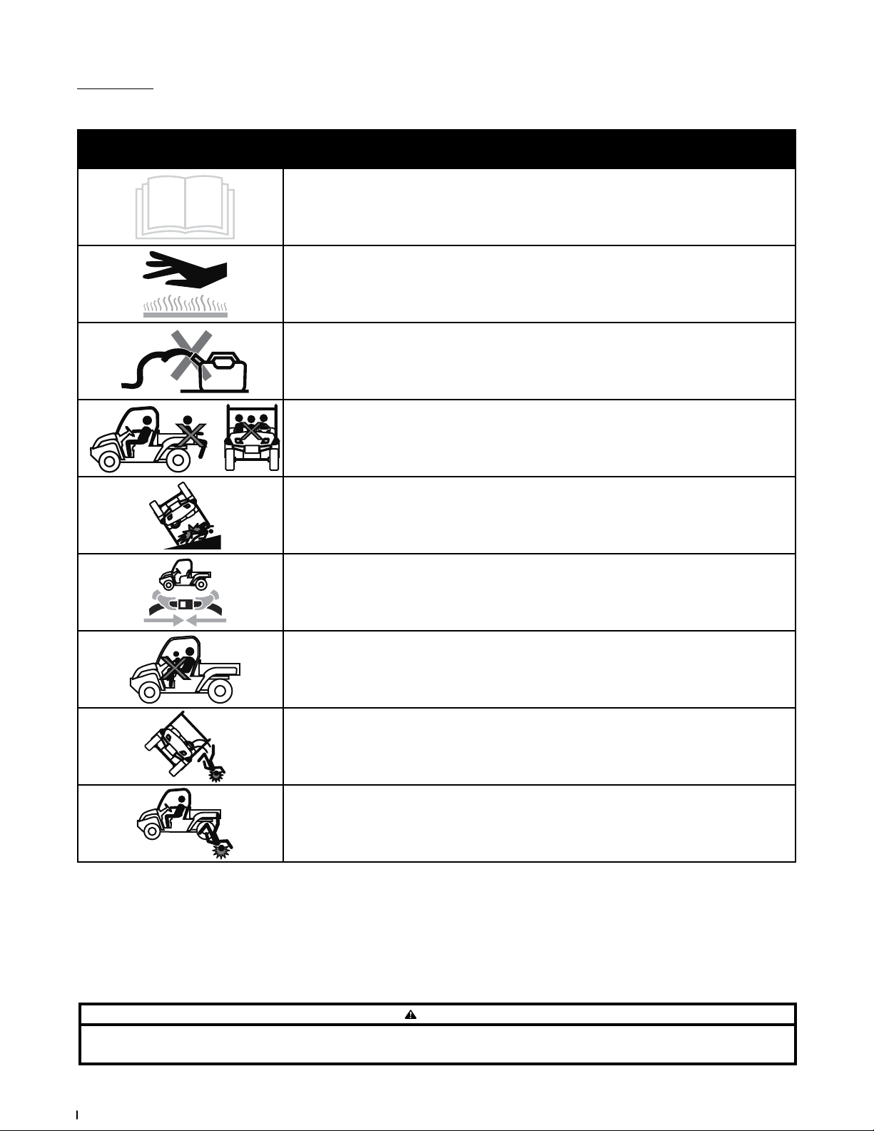
Safety Symbols
This page depicts and describes safety symbols that may appear on this product. Read, understand, and follow all instructions on the machine before
attempting to assemble and operate.
Symbol Description
READ THE OPERATOR’S MANUAL(S)
Read, understand, and follow all instructions in the manual(s) before attempting to assemble and
operate
WARNING— HOT SURFACE
Hot Surface - Do not touch.
WARNING — GAS CONTAINER
Avoid injury from explosion. Do not place gas container in cargo box when fueling.
WARNING— RIDERS MUST BE IN SEATS
No riders in cargo box or anywhere other than seats.
MAX 15º
WARNING— SLOPES
Do not operate on slopes greater than 15°.
WARNING— SEAT BELTS
Always wear the seat belt when operating the utility vehicle.
WARNING— ONE RIDER PER SEAT
Only one person in each seat.
WARNING— ROLL OVER
Falling off or rollover may cause serious injury or death.
WARNING — RIDERS FALLING
Riders can fall off and be seriously injured or killed.
WARNING
Your Responsibility — Restrict the use of this power machine to persons who read, understand and follow the warnings and instructions in this manual and on the machine.
SAVE THESE INSTRUCTIONS!
6 Sectio n 2 — important Safe oper ation practiceS
Page 7

Controls & Operation 3
(A)
(B)
(E)
(F)
(H)
(C)
(D)
(Q)
(J)
(I)
(K)
(N)
(L)
(M)
(O)
(P)
(G) (G)
(H)
(H)(H)
(R)
(R)
(S)
-
+
(c)
(a)(b)
(d)
(i)
(h)
(g)
(e)
(f)
(j) (j)
Seat Belt Warning Indicator (d)
The seat belt warning indicator located in the
instrument cluster will flash for 8 seconds once the key
is turned to the ON position to remind the operator
and passenger to fasten their seat belt. See Figure 3-2.
Low Voltage Indicator (e)
The low voltage indicator will illuminate when your
battery drops to 11.6 volts.
Fuel Level Indicator (f)
The Fuel Level is divided into 5 segments and flashes
at the lowest increment. See Figure 3-2.
Gear Position Indicator (g)
The gear position indicator displays the gear (P, R, N
or D) that the gear selector is in.
Headlight Indicator (h)
The headlight indicator illuminates when the
headlights are in use.
Differential Lock/4WD Indicator (i)
The two front wheels on the differential lock /4WD
indicator highlight when the 4WD is ac tivated. A
small “X” appears between two rear tires when the
differential lock is activated.
2WD 4WD
Figure 3-1
Read this operator’s manual, safety symbols, and
operating instructions on the vehicle before operating.
Compare the illustrations in this manual with your
unit to familiarize yourself with the location of various
controls and adjustments. Reference to the right or
left hand side of unit is observed from the operating
position. Save this manual for future reference.
IMPORTANT: Refer to the Engine Operator’s Manual
before operating this vehicle to familiarize yourself
with the engine controls and adjustments.
Instrument Cluster (A)
The instrument cluster is located in the middle of the
dash panel. It contains multiple displays, indicator
lights and mode buttons. It displays Fuel Level,
Vehicle Speed (KM/H, MPH), Gear Selection (D, N,
R or P) and the Odometer reading when the key is
turned to the “ON” position. In addition, the Seat
Belt Warning Indicator will flash for 8 seconds to
remind the operator and passenger to fasten their
seat belt.
The MODE (a) button switch changes the display
from distance driven (KM/MILE) to time of use (Hrs.).
The KM/MILE (b) button switch changes the display
from KM/H to MPH. See Figure 3-2.
Figure 3-2
Odometer/Hour Meter (c)
The odometer/hour meter is located in the instrument
cluster. To display the hour meter, press the mode
button switch to change the display from distance
driven to time of use. It records the elapsed time when
the key is in the RUN position. See Figure 3-2.
Turn Signal Indicator Lights (If Equipped) ( j)
The turn signal indicator lights flash when one of the
turn signals is activated. The turn signal indicator
lights require the installation of the trail light kit.
Choke Knob (B)
The choke knob is located to the right of the ignition
switch on the dash. The choke is used when starting
a cold engine. To set, pull out to engage, push in to
disengage.
7
Page 8

Ignition Switch (C)
High Beam
Position
RUN
Position
START
Position
WARNING
Never leave a r unning mach ine unatte nded. Always sh ift into pa rk,
stop engine and remove key to prevent unintended starting.
The ignition switch is located to the right of the
steering wheel. To start the engine, insert the
key into the ignition switch and turn clockwise to
the START position. Release the key into the RUN
position once engine has started. To use the high
beam feature, turn the key back to the high beam
position. The high beam indicator in the instrument
cluster will illuminate. See Figure 3-2 & Figure 3-3.
Refer to Starting Engine section of this manual for
detailed starting instructions.
Seats (G)
The driver’s seat can be adjusted either forward or
rearward. Push the adjustment handle to the right,
slide the seat into the desired position and release
the adjustment handle to lock the seat into place.
See Figure 3-5.
Figure 3-5
Note: The passenger seat is not adjustable.
Auxiliary Switch Panel (L)
The auxiliar y switch panel is located on the right
hand side of the dash panel above the handhold.
When adding accessories requiring switches, use
this area of the dash panel to install the desired
switches.
2WD/4WD Switch
The 2WD/4WD switch is located on the
auxiliary switch panel and is used to switch
between 2WD and 4WD. When the 4WD is
activated the front wheels will highlight on
the differential lock /4WD indicator.
Occupant Protective Structure (OPS) (M)
This utility vehicle is equipped with an Occupant
Protective Structure (OPS) and seat belts. When used
together they are effective in reducing crushing
injuries to the operator and passenger in the event
of an accidental rollover or tip-over. The safety
provided by the OPS is minimized if the seat belt is
not properly adjusted AND buckled.
Figure 3-3
Gas Pedal (D)
The gas pedal is located to the right of the brake
pedal, beneath the dash panel. See Figure 3-1.
Depressing the gas pedal will move the vehicle in
the direction selected on the shif t lever. As the pedal
is slowly depressed, speed will continue to increase
to the desired speed. Releasing the pedal will reduce
the speed, but will not completely stop the vehicle.
The brake must be applied to stop vehicle.
Brake Pedal (E)
The brake pedal is located to the left of the gas pedal,
beneath the dash panel. See Figure 3-1. Remove foot
from accelerator pedal and apply pressure to the
brake pedal until vehicle slows down and stops.
Seat Belts (F)
The seat belts are located on the outside of the
driver and passenger seats. Pull across your chest
and lap and secure it to the seat belt latch located
near the center console.
Note: Seat belt warning indicator will flash for 8 seconds
once the key is turned to the ON position to remind the
operator and passenger to fasten their seat belt.
WARNING
Always wear the seat belt when operating the utility vehicle.
The position of the lap belt portion of the seat belt
should be positioned for both the operator and the
passenger before driving. See Figure 3-4.
Figure 3-4
Bed Tie-Down Rings (H)
The bed tie-down rings can be used to secure items
for transporting.
Differential Lock Lever (I)
The differential lock lever is located in the center
console between the seats. When engaged, the
differential lever locks the rear differential, giving
equal power to both rear wheels. In addition, when
the differential lock lever is in the ON position, the
Differential Lock Indicator located in the instrument
cluster will illuminate. See Figure 3-2.
Shift Lever (J)
The shift lever is located in the center console
P
between the seats and has four positions
(PARK, REVERSE, NEUTRAL and DRIVE). The
brake pedal must be fully depressed when
moving the shift lever. One of the four gear
positions will be displayed in the instrument
R
cluster. See Figure 3-2.
IMPORTANT: Never force the shift lever or
N
attempt to shift while in motion. Doing so may
result in serious damage to the utility vehicle’s
transmission.
D
12V Power Outlet (K)
The 12V power outlet is located on the right side
of the dash panel. It is used for the convenience of
plugging in accessories that require a power source
with a maximum load of 7.5A at 12V.
WARNING
Always wear the seat belt when operating the utility vehicle.
Use the following guidelines when using a utility
vehicle equipped with OPS:
1. Be aware of overhead clearances in the area
of operation. Check for clearance of door (or
gate) openings and other overhead objects
such as utility lines and tree branches.
Overhead objects could catch the OPS and
upset the utility vehicle.
2. Do not modify the OPS by drilling holes for, or
welding accessories to the structure.
3. Do not use the OPS to pull objects with the
utility vehicle. Use ONLY the utility vehicle
hitch for pulling.
4. Do not operate the utility vehicle without the
OPS and do not remove the OPS.
5. In the event of an accident, have the OPS
carefully inspected and, if necessary, replaced
by your Cub Cadet dealer. Do not attempt to
repair the OPS.
Cup Holders (N)
The cup holders are located on top of the dash panel
on both the lef t and right hand sides.
WARNING
Never operate this vehicle while under the influence of alcohol
or drugs. Doing so can result in serious personal injury or death
Cargo Bed (O)
The cargo bed maximum capacity is 400 lbs. (181 kg),
the passenger + operator max weight is 500 lbs. (226
kg), total cargo bed + passenger/operator weight is
900 lbs. (408 kg). The max towing weight is 1200 lbs.
(544 kg) and the max tongue weight is 180 lbs. (81 kg).
The cargo bed may be tilted for dumping loads. Push
forward on the cargo bed latch lever to unlock the
bed and manually lift the cargo bed. See Figure 3-1.
Note: Access to the engine is achieved by raising the
cargo bed.
IMPORTANT: Do not exceed the vehicle’s Total
Payload Capacity of 900 lbs (408 kg), which includes
driver, passenger, accessories, tongue load and cargo.
Do not exceed 400 lbs. (181 kg) in the cargo bed.
8 Section 3— contro lS & operation
Page 9

Cargo Bed Latch Lever (P)
The cargo bed latch lever is located on the left/
drivers side of the utility vehicle and is used to
dump/tilt the cargo bed.
Hitch (Q)
The hitch is located on the rear of the utility vehicle
on the frame. The the max towing capacity is 1200
lbs. (544 kg). The max tongue weight is 180 lbs. (81
kg).
Tailgate Latches (R)
The tailgate latches are located on the tailgate and
are used to open the tailgate.
Fuel Cap (S)
The fuel cap is located on the right/passenger’s side
of the vehicle to the rear of the passenger’s door.
Operation
Tire Inflation
IMPORTANT: Inflation pressure in all tires is 12 psi.
Overinflating above recommended tire pressure can
reduce the life of the tire. Check tire pressures before
each use.
WARNING
Excess ive pressure (ab ove 12 psi) may cause the ti re/rim asse mbly
to burs t with suff icient forc e to cause sever e injury or de ath.
Starting Engine
WARNING
This is an off-road utility vehicle and it should not be operated on
public highways. Know and comply with all laws and regulations
governing the use of off-highway vehicles in your area.
IMPORTANT: Before starting the engine, read this
manual and the Engine manual thoroughly to
understand all instructions.
WARNING
Do not run a n engine in an en closed are a. Engine exh aust contai ns
carbon monoxide, which is very poisonous and can cause death.
Move the vehi cle outsid e or to a well ventil ated area.
1. While sitting in the seat with your seat belt
fastened, insert key into ignition switch.
2. The engine can be started with the shift lever
in the “P” park position or with the shift lever
in “N” Neutral and the brake held down.
3. Pull out the choke knob if engine is cold.
4. Turn key to the START position.
IMPORTANT: DO NOT run the starter
continuously for more than 5 seconds,
otherwise the batter y may discharge quickly.
5. Release key to the RUN position when engine
starts.
6. If engine does not start, wait a few seconds
and repeat steps 5 & 6.
7. After engine starts, push in choke knob.
8. Place shift lever in the desired gear, release
brake and press accelerator pedal slowly.
IMPORTANT: Do not operate the engine
under full load until engine has warmed up.
Stopping Engine
1. To stop utility vehicle, release accelerator pedal
and depress brake pedal until vehicle comes to
a complete stop.
2. Move shift lever into PARK.
3. Turn key switch to STOP position.
4. Remove the key when not in use.
WARNING
The vehic le may roll if the sh ift lever is not i n the PARK position.
Refueling Fuel Tank
WARNING
Avoid inju ry from expl osion or fire. D o not carry fue l or other
flammable liquids in vehicle or cargo bed.
1. Stop vehicle on a level surface and move the
shift lever into PARK.
2. Turn the ignition key to the STOP position and
remove key.
3. Allow engine to cool for five minutes before
adding fuel.
4. Clean area around fuel cap and remove.
5. Fill tank with fresh, unleaded, regular grade
fuel only to bottom of filler neck. Use a
minimum of 87 Octane (10% Ethanol Max.).
6. After refueling, push the fuel cap downward on
the fuel tank f ill neck and turn clockwise until it
clicks to tighten. Always re-install the fuel cap
tightly onto the fuel tank after removing.
Driving Utility Vehicle
1. Adjust the operator’s seat to the most
comfortable position that allows you to
operate all controls and pedals. See Seats
section in Controls & Features, page 8.
2. Adjust the seat belt to fit comfortably around
your lap, then buckle the seat belt.
WARNING
Do not ope rate the vehicle wi thout the OPS in pl ace and the
seat belt fastened securely around your waist and chest.
3. Start the engine as instructed earlier and
make sure the front wheels are turned to the
desired direction of travel.
4. Move the shift lever in the center console
to the desired setting. To avoid damaging
transmission, depress brake pedal fully and
make sure vehicle is completely stopped
before shifting into Forward, or Reverse.
WARNING
Do not stop or start suddenly when going uphill or downhill.
Be cautious when changing direction on slopes. Apply brakes
when going down slopes to maintain control of vehicle.
6. Release brake pedal and slowly apply pressure
to the accelerator pedal.
7. Release accelerator and apply brake pedal
evenly and firmly to slow down or stop.
Note: When travelling in reverse, the reverse
speed limiter will not allow the utility vehicle
to travel more than 10 mph.
2WD/4WD
CAUTION
When trave ling at road spe ed, use only 2WD. When d riving on
icy, wet or lo ose surface s, make sure the veh icle is corre ctly
loaded to avoid skidding and loss of steering control. Reduce
the spee d and engage fro nt wheel drive. Ac cident may
occur if t he vehicle is sud denly braked, s uch as heavy towe d
loads shifting forward causing loss of control. The braking
characteristics are different between two and four wheel
drive. Be aw are of the diff erences and op erate caref ully.
To activate the 4WD press down on the upper half of
the 2WD/4WD switch. To return to 2WD, press down
on the lower half of the 2WD/4WD switch. Switching
between 2WD and 4WD can be done while the
utility vehicle is in motion. If the wheels are slipping
and/or the utility vehicle is stuck, stop the forward
or reverse motion and then switch between 2WD
and 4WD.
Differential Lock
WARNING
To avoid transmission damage, injury, or turf damage, drive
slow when operating utility vehicle with differential lock
engaged as steering response is noticeably reduced. Also, do
not drive the utility vehicle with the differential lock engaged
on concrete, asphalt or any high traction surfaces.
The differential lock lever is located in the center
console between the seats. See Figure 3-1.
Note: The dif ferential lock can be engaged at
low speeds under low loads, but the following
instructions to engage the differential lock are
recommended.
1. To engage; stop utility vehicle, place into
NEUTRAL, and pull the lever upward into the
ON position. The differential will then lock and
remain so until it is disengaged, giving equal
power to both rear wheels.
IMPORTANT: Engage the differential as the
last option when stuck in mud or similar
situation or when the left and right side
wheels are turning at slightly different speeds.
2. To disengage the differential lock ; stop the utility
vehicle, place the shift lever in NEUTRAL, and
push the differential lock lever downward to the
OFF position.
Loading the Cargo Bed
WARNING
The utili ty vehicle may b ecome unstab le if the cargo be d is
loaded incorrectly. Avoid loose and unsecured loads or uneven
loading of material.
1. Verify cargo bed is securely latched before
loading.
2. Securely anchor all loads in cargo bed and do
not load beyond maximum capacity.
Note: The maximum box capacity is 400 lbs.
(181 kg).
3. When loading objects into cargo bed, be sure
load is securely anchored and evenly distributed.
4. Do not load above height of cargo bed.
Load could shift forward striking driver or
passenger or cause driver to lose control of
vehicle.
Section 3 — controlS & operation
9
Page 10

5. Avoid loads which exceed physical dimensions
2
1
1
2
Cargo Bed
Latch Lever
Lift Up Cargo Bed
From Here
of cargo bed.
6. Avoid concentrated loads at rear or sides of
cargo bed. Be sure load is distributed evenly.
7. Reduce load and ground speed when
operating over rough or hilly terrain. DO NOT
overload vehicle. Limit loads to those that can
be safely controlled.
Raising & Lowering the Tailgate
1. Unlatch the tailgate from cargo bed and
lower. See Figure 3-6 & Figure 3-7.
Figure 3-6
Figure 3-7
2. Raise and re-latch the tailgate to the cargo bed.
See Figure 3-7 & Figure 3-8. Do not drive the
vehicle with tailgate in the lowered position.
Figure 3-8
Raising & Lowering Cargo Bed (Dumping Loads)
To prevent the possibility of bodily injury from unintentional
lowerin g of the cargo be d, be sure vehic le is on a level and s table
surf ace and in the PARK posi tion before r aising carg o bed.
WARNING
WARNING
A loaded c argo bed can be ve ry heavy. Do not at tempt to
dump a heavily loaded cargo bed.
1. Park the vehicle safely on level ground.
2. Empty heavy cargo by hand.
3. For light loads, unlatch cargo bed by pushing
forward on the cargo bed latch lever. While
holding the latch lever forward with one
hand, lift the cargo bed with your other hand.
See Figure 3-9.
Figure 3-9
4. Once unloaded, lower bed and securely
latch before operating unit. Do not drive the
vehicle with cargo bed in the raised position.
Towing Loads
WARNING
To help preven t personal inj ury due to loss of co ntrol or
tipping, always tow a load slow enough to maintain control.
1. Do not tow a load that exceeds 1200 lbs. (544
kg) rolling weight (i.e. trailer plus cargo) and
never exceed 180 lbs. (81 kg) tongue weight.
2. Go slow when towing a heavy load. Allow
for increased braking distance. Tow load at a
speed slow enough to maintain control.
3. Do not tow on slopes greater than 5°.
4. Be cautious when towing downhill, even
on a gradual slope or when turning. The
extra weight tends to push the tow vehicle
and may cause you to lose control (braking
and steering ability are reduced; towed
equipment may jack-knife).
IMPORTANT: Extreme angles such as high
railroad crossings can place high bending
loads on hitch connection.
5. Do not modify the hitch in any way.
How to load a Utilit y Vehicle into a Truck or onto a Trailer
WARNING
Always pa rk the truck or tr ailer in a flat ar ea, set the parki ng
brake, tur n the ignition of f and chock th e wheels to preven t
any unexpected movement while loading the utility vehicle.
WARNING
Fully secure the loading ramps to the truck or trailer with
tie-do wn straps or cab les to prevent the r amps from slid ing
off wh ile loading. Kee p bystanders a nd/or helpers aw ay from
ramps while loading.
Due to the overall size and dimensions, loading a
utility vehicle into a truck or onto a trailer is a task
that requires precision and the proper equipment to
be achieved safely. By following the steps outlined
below you’ll be able to select the proper equipment
to do the job and safely load and unload your utility
vehicle.
Determine if your truck or trailer is sufficient for
the task
Loading a utilit y vehicle into a truck or trailer that
can’t suppor t its weight is extremely dangerous. It is
important that before any actual loading is done, make
sure your truck or trailer and loading ramps are sufficient
for loading and hauling the utility vehicle. Here are some
of the variables you need to take into account:
• Length and width: Measure the size of your
truck or trailer by taking width and length
measurements at the floor level. Compare these
measurements to the width and length of your
utility vehicle to make sure it will f it comfortably.
• Weight Capacity: Making sure your truck or
trailer can handle the payload of your utility
vehicle is another critical task before any
loading is done. If using a truck, the payload
capacity must be a minimum of ¾ ton. If
hauling on a trailer, remember that the towing
capacity of the vehicle will be reduced by the
added weight of the utility vehicle.
• Tailgate Considerations: If the payload
capacity is sufficient for hauling in a truck, the
last thing left to consider is your truck’s bed
length. Make certain that your truck bed is
long enough to allow the truck’s tailgate to
close completely when the utility vehicle is
loaded into the truck bed.
Choosing the proper loading ramp(s)
Choosing a reliable ramp and understanding how to
properly use it is far and above the best option for safely
loading a utility vehicle into your truck or onto your
trailer. Take a look at the considerations you should have
in mind when choosing the proper ramp(s):
• Capacity: Utility vehicles are not evenly
balanced, meaning it’s necessary to check the
axle weights before you make any choices
regarding ramps. A typical ramp’s capacity is
based upon two axles with equally distributed
loads. We recommend 3,000-lb minimum
capacity ramp(s) as the appropriate option for
your two-person utility vehicle.
• Offset track widths: Your utility vehicle
has an offset track width front and rear, it’s
important to factor this in to your ramp
placement and ramp width needs. Ramps
need to be wide enough to accommodate the
difference in the distances between the front
two wheels and the rear two wheels.
• Ground clearance and wheelbase: Utility
vehicles which have low ground clearance
(under 4”) and a relatively long wheelbase
(98” or more), make them prone to bottoming
out at the crest when using straight ramps.
As a solution to this issue we suggest using
arched ramps.
10 Section 3— contro lS & operation
Page 11

• Load Height: As with any ramp application,
the distance from the ground to the truck
bed or trailer impacts the overall length of
the ramp you will need, the greater the load
height, the longer the ramp should be. Some
ramp manufacturers and retailers provide
load height calculators to help you determine
the correct ramp length you will need to
safely load your vehicle.
Note: If you are still unsure of what types
of ramps you will need to get the job done
and are having trouble understanding these
instructions, check with your local ramp or
utility vehicle retailer for assistance.
Loading the Utility Vehicle
If your truck or trailer’s load capacity is sufficient
to transport the utility vehicle and you obtain the
proper loading ramps and equipment to safely
secure the utility vehicle to the truck or trailer, the
only thing lef t to do is load it. Here’s how to best
accomplish this task:
1. Proceed with extreme caution. It is very
difficult to overcome a mistake while in the
loading process.
2. Park the truck or trailer in a flat area, set the
parking brake, turn the ignition off and chock
the wheels.
3. Face the truck bed or trailer towards a slight
incline, which will reduce the steepness of the
loading angle by bringing the bottom of the
ramps up on the slight incline. See Figure 3-10.
4. Place the ramp fingers or plate edges on the
edge of the trailer or truck bed. See Figure 3-11.
Figure 3-11
5. Use tie-down straps or cables to secure the
ramps to the trailer or truck, via the bumper
(steel bumpers only) or trailer hitch safety
chain loops. Refer to instructions provided
with the ramp.
6. If your utility vehicle is supplied with a roof
and/or windshield, remove or fully secure
them prior to loading. Roofs and windshields
are not designed to withstand the wind
speeds that the open road can generate, so
it’s best to remove them entirely to prevent
any damage or accidents.
7. Follow all safety rules provided in this manual
along with the manuals supplied by the trailer
and ramp manufacturer. Carefully load the
utility vehicle onto the truck or trailer.
8. Once the utility vehicle is on the truck or
trailer, move the shift lever into PARK and
secure the utility vehicle to the truck or trailer.
Tie-down strap placement will depend on
your truck or trailer. Be sure to use only tie
down straps sufficient for the load capacity.
If loaded onto a truck, close the tailgate once
the utility vehicle is secured to the truck bed.
9. Stop periodically to ensure that your tie-down
straps have not loosened and that the utility
vehicle remains securely in place.
IMPORTANT: Know the total height of your
vehicle with the utility vehicle loaded
before transporting. Be sure to check for
low clearance bridges, doorways etc. prior to
traveling under them, the added height above
the height of your truck could cause clearance
issues and damage to both vehicles.
Figure 3-10
Section 3 — controlS & operation
11
Page 12

Product Care 4
Element
Latch
Cover
Cap
Before E ach Use First 10 Hours
Change Air Filter^ Inspect/Clean
Inspect Ball Joints
Inspect Brakes
Inspect Front and Rear Shocks
Lubric ate A-Arms †
Tighten Lug Nuts
Inspec t OPS and Seat Bel ts
Inspect Tires
Change Transaxle Oil
^ Change more frequently if unit is operated in extremely dusty conditions.
† Lubricate after each use if unit is run through water deeper than axle.
NOTE: For information regarding engine service, see the separate Engine Owner’s Manual included with your unit.
P
P
P
Every 20 Ho urs/2
Months
P
Every 50 Hours
P
P
Every 100 Ho urs or
Yearly
P
P
P
Every 50 0 Hours or
2 Yea rs
Service Dates
Cleaning
The body panels can scratch easily. Do not use
car wax on the body panels. The use of standard
car wash soap is acceptable for cleaning the body
panels. Avoid any abrasive cleaner or rubbing
compounds for these will damage the body panels.
Dry thoroughly to avoid water spots.
WARNING
DO NOT use a pr essure washe r. Damage may occur if d irect
hose spray comes in contact with intake openings, or any other
electrical components, i.e. at instrument cluster or under dash.
Tire Pressure
WARNING
Excess ive pressure (ab ove 12 psi) may cause the ti re/rim asse mbly
to burs t with suff icient forc e to cause sever e injury or de ath.
The recommended operating tire pressure is 12 psi
for all tires. Overinflating above recommended tire
pressure can reduce the life of the tire. Check tire
pressures before each use.
Seat Belts
Check proper function before each use. Replace
seat belt assembly if any damage is found. If damage
is noted, contact your Cub Cadet dealer.
Lug Nuts
Check torque of lug nuts after first 10 hours of use.
Tighten lug nuts in a diagonal pattern. Torque lug
nuts to 65-75 lb-ft using a torque wrench.
Air Filter
1. Pull up on latch and turn counter-clockwise to
release air cleaner cover. See Figure 4-1.
Figure 4-1
2. Remove cover. Remove and inspect air cleaner
element. If excessively dirty or damaged,
replace element.
3. Reattach cover and secure with latch.
IMPORTANT: When reattaching cover, make
certain that the cap is pointing downward.
See Figure 4-1 inset.
Engine Oil
WARNING
If the engi ne has been rece ntly run, the engi ne, muffle r and
surrou nding metal su rfaces may be hot a nd can cause bu rns
to the ski n. Allow to cool for 30 mi nutes. Exerci se caution to
avoid burns.
Refer to your Engine Owner’s Manual for how often
to check and change your engine oil. To drain the oil
follow the steps below:
1. Place the oil drain hose down through the hole
closest to the oil drain hose. See Figure 4-2.
Figure 4-2
2. Turn the plug counterclockwise and allow oil to
drain into a suitable container. See Figure 4-2.
3. Turn the plug clockwise, wipe any residue oil
from the oil drain hose and take the oil drain
hose out of the hole to return to its normal
position.
12
Page 13

4. Refill the engine with new oil as instructed in
Engine
Fill/Dipstick
Drain Plug
Fill Plug
the engine operator’s manual. See Figure 4-3
for engine fill/dipstick location.
4. Access drain plug on underside of machine
and remove plug. See Figure 4-5.
Cleaning Battery & Terminals
1. Remove battery from vehicle. Always remove
negative cable first when disconnecting.
2. Wash battery with solution of four
tablespoons of baking soda to one gallon of
water.
3. Rinse the battery with plain water and dry.
4. Clean terminals and battery cable ends with
wire brush until bright.
5. Apply petroleum jelly or silicone spray to
terminals to prevent corrosion.
6. Install battery. Always install negative cable
last when connecting.
Charging Battery
Figure 4-3
Lubrication
Use a grease-gun filled with No. 2 Multipurpose
Lithium Base Grease for the eight zerk fittings (four
on each side) on the A-Arms. See Figure 4-4.
Figure 4-4
Transaxle
Figure 4-5
5. Allow oil to drain into a suitable container.
6. Check O-ring on drain plug and replace if
missing, damaged or in poor condition.
7. Remove fill plug. See Figure 4-6.
Figure 4-6
8. Add 32 oz. (1 quart) of Shell Spirax S4 TXM
through the fill plug port.
9. Re-Install fill plug. See Figure 4-6.
Battery
WARNING
Charge b attery in a well v entilated area a nd keep away
from an o pen flame or pil ot light as on a water h eater, space
heater, fur nace, clothes dr yer or other gas ap pliances.
If the vehicle has not been put into use for an
extended period of time, charge the battery with an
automotive type 12V charger for a minimum of one
hour at six amps. The Low Voltage Indicator on the
instrument cluster will illuminate when your battery
reaches 11.6 volts.
Jumping Battery
WARNING
Do not att empt to jump st art a batte ry. Do not smoke ne ar batter y
and wear eye p rotectio n and gloves wh en handling b attery.
IMPORTANT: If your battery is dead, then follow the
instructions for charging the battery.
Fuses
1. Remove hood latches and lower the hood.
See Figure 4-7.
WARNING
The fluid for your transaxle has been specially formulated
to ensure the safe and proper operation of your vehicle.
When changing your transaxle fluid replace it with part
no. 737-05136 – Shell Spira x S4 TXM 10W/30. Failure to use
Shell Spi rax S4 TXM 10W/30 oil may r esult in a failur e of your
transaxle which could result in property damage or personal
injury. DO NOT substitute.
1. Park vehicle on level surface and move the
shift lever into PARK.
2. Allow the unit sufficient time to cool (30
minutes) before attempting any maintenance
or repairs.
3. Locate the transaxle below the cargo bed in
the rear of the vehicle.
WARNING
The bat tery produce s a flammable an d explosive ga s. Do not
smoke nea r battery. Wear eye pr otection and g loves when
handli ng the batter y. Do not allo w direct meta l contact
across b attery pos ts or between t he positive bat tery post or
termin al and adjacent me tal parts. Th e battery is se aled and
is mainte nance free. Acid l evels cannot be c hecked and flu id
can not be a dded.
WARNING
CALIFORNIA PR OPOSITION 65 WARNING: Bat tery post s, terminals,
and related accessories contain lead and lead compounds,
chemic als known to the St ate of Califo rnia to cause c ancer and
reproductive harm. Wash hands after handling.
IMPORTANT: If removing the battery for any
reason, disconnect the NEGATIVE (Black)
wire from its terminal first, followed by the
POSITIVE (Red) wire. When re-installing the
battery, always connect the POSITIVE (Red)
wire to its terminal first, followed by the
NEGATIVE (Black) wire. Be certain that the
wires are connected to the correct terminals;
reversing them could cause damage to your
engine’s charging system.
Figure 4-7
Section 4 — Produc t care
13
Page 14

2. Remove the Acc (accessory) electrical fuse and
Acc Fuse
System Fuse
Voltage
Regulator
Fuse
Mounting
Bolts
Brake Piston
Slide Pins
Brake Caliper
Assembly
Adjustment
Collar
replace if needed with proper rated amp fuse.
See Figure 4-8.
3. Loosen but do not remove the five lug nuts
from the axle hub. See Figure 4-10.
2. Remove brake caliper assembly from brake
disc. See Figure 4-12.
Figure 4-8
3. Raise and secure hood.
4. Raise the driver’s seat.
5. Remove the appropriate electrical fuse and
replace if needed with proper rated amp fuse.
See Figure 4-9.
6. Lower the seat.
Figure 4-9
Changing Brake Pads
WARNING
Using an un stable lif ting device and ve hicle suppor ts may
result i n bodily injur y. Use a safe lifti ng device and sup ports to
work on rai sed vehicle.
To gain access to the brake pads, remove the wheel
as described below. If less than .030” of material
remains on the pad, replace.
NOTE: Brake pads must be replaced as a set, i.e.,
right rear and left rear.
Removing the Wheels
1. Stop the vehicle on a level surface and move
the shift lever into the PARK position.
2. Turn the ignition key to the STOP position and
remove the key.
Figure 4-10
4. Raise the front or rear of the vehicle with a
safe lifting device and place support stands
under vehicle frame.
WARNING
When lif ting the rear of t he vehicle for any r eason, DO NOT
engage the rear wheels.
5. Remove the five lug nuts and the wheel.
To change the brake pads, follow the steps below.
Removing Brake Pads
1. Remove mounting bolts securing caliper and
brake pads to steering knuckle. See Figure 4-11.
Figure 4-11
Figure 4-12
IMPORTANT:
from the brake hose. Stressing the brake hose
can damage it and cause leaks.
3. Remove brake pads from brake caliper
assembly.
4. Clean and lube slide pins. See Figure 4-12.
5. Press in brake piston. See Figure 4-12.
IMPORTANT: When pressing in brake piston,
take care not to damage rubber piston seal.
6. Place brake pads on slide pins.
7. Move caliper into place, making sure brake
disc is between the two brake pads.
8. Apply Loctite® 242 to the threads of the bolts
removed earlier.
9. Secure caliper and brake pads with mounting
bolts. Torque the mounting bolts to 22-26 ft. lbs.
Do not let the caliper hang
Reinstalling the Wheels
1. Place the wheel on the axle hub and secure
with the four lug nuts.
2. Tighten the lug nuts diagonally until snug.
3. Remove support stands and lower vehicle.
4. Finish tightening the lug nuts to 65-75 lb-ft
using a torque wrench.
Front & Rear Shocks
All four shocks are adjustable. Adjust as needed for
comfort/load level. Turn the collar at the bottom of
the shocks to one of the five positions. Adjust the
left and right side equally. See Figure 4-13.
14 Sectio n 4— Produc t care
Figure 4-13
Page 15

See Figure 4-14. If excessive oil leakage appears,
Shock
Shock
Ball Joints
Tie Rod End
have shocks repaired or replaced by your local Cub
Cadet dealer.
Figure 4-14
Ball Joints
See Figure 4-15. If excessive wear appears, have ball
joints or tie rod ends replaced by your local Cub
Cadet dealer.
Figure 4-15
Occupant Protective Structure (OPS)
Periodically (at least every six months), visually
inspect the OPS and seat belts. It is important that
these features be inspected for damage and proper
function before each use, or daily. Contact your Cub
Cadet dealer and replace the belt assembly if any
damage is found.
If an accident has occurred which may have
damaged the OPS, have the OPS thoroughly
inspected by your Cub Cadet dealer.
WARNING
To ensure the s tructural i ntegrity of th e OPS to provide
occupant protection, do not attempt to straighten or weld
the OPS. A dam aged OPS should b e replaced.
If the OPS is removed for any reason, make sure the
proper hardware is used to reinstall it, and that the
recommended torque values are applied to the
fasteners.
If you are not installing new bolts when replacing
or reinstalling the OPS, apply Loctite ® 242 to the
threads of the bolts that were removed. Torque the
bolts to 50-55 ft. lbs using a torque wrench.
Drive Belt
IMPORTANT: See your Cub Cadet Dealer to have your
drive belt replaced.
Troubleshooting
1. Engine will not start
• Battery has low voltage.
• Loose or corroded battery connections.
• Fuse is blown.
• Spark plug wire is loose or disconnected
• Faulty spark plug or coil
• No Fuel or improper fuel.
• Plugged fuel filter.
• Defective starter solenoid.
• Open-circuit in wiring.
• Shift lever not in correct gear.
• Bad brake pressure switch/sensor.
• Brake is not depressed (when starting
in neutral).
2. Engine is difficult to star t
• Engine is cold.
• Choke not being used or adjusted
properly.
• Plugged fuel filter.
• Carburetor not adjusted properly or
dirty.
• Engine oil viscosity too heavy.
• Spark plug is fouled.
• Faulty spark plug or wire.
• Loose or corroded electrical
connections.
• Stale or improper fuel.
3. Engine misfires under load
• Faulty spark plug.
• Stale or dirty fuel.
• Plugged fuel filter.
• Faulty coil or wire.
4. Engine does not restart when warm
• Poor quality fuel.
• Very hot weather conditions.
• Fuel tank vent plugged.
• Dirt in fuel filter.
5. Entire electrical system does not work
• Blown fuse.
• Loose or corroded connections.
• Dead or Faulty battery.
6. Dead battery
• Shorted starter solenoid.
• Key switch not turned to STOP position.
• Faulty batter y.
7. Battery will not take a charge
• Dead battery.
• Loose or corroded connections.
8. Dif ficult to shift
• Idle speed too fast.
• Gears not lined up. Tap throttle and
let it return to idle. If still hard to shift,
contact your nearest Cub Cadet dealer.
9. Indicator lights do not come on when key
switch is in START position
• Faulty bulb.
• Faulty wiring.
• Faulty sensor.
10. Engine runs unevenly
• Loose electrical connections.
• Choke (if equipped) or throttle cable
sticking.
• Fuel line or fuel filter plugged.
• Stale or dirty fuel.
• Improper fuel.
• Air cleaner element plugged.
• Carburetor not adjusted correctly.
• Spark plug is fouled.
11. Engine overheats
• Air cleaner element missing or
plugged.
• Carburetor air intake tube plugged.
• Engine oil low.
• Engine operated too long at slow
engine speed.
12. Engine knocks
• Stale or low octane fuel.
• Engine overloaded.
13. Engine loses power
• Engine overheating.
• Too much oil in engine.
• Faulty spark plug.
• Fuel supply being restricted.
• Fuel filter plugged.
• Fuel line pinched or kinked.
• Fuel pump output not adjusted to
specification.
• Improper fuel.
• Air cleaner element plugged.
14. Starter does not work
• Loose or corroded connections.
• Low battery output.
• Dead or Faulty battery.
• Faulty starter.
Section 4 — Produc t care
15
Page 16

15. Starter cranks slowly
• Low battery output.
• Dead or Faulty battery.
• Engine oil too heav y.
• Loose or corroded connections.
Notes
16. Battery light comes on when engine is
running
• Low engine speed.
• Faulty voltage regulator.
• Faulty batter y.
• Faulty alternator or loose alternator
belt.
• Damaged wiring harness
17. Vehicle will not move
• Shift Lever still in Neutral.
• Shift Lever still in PARK.
• Broken or cut drive belt.
• Safely check to see if the vehicle
Attachments & Accessories
Visit cubcadet.com for all available Challenger Utility Vehicle attachments and accessories.
will go in Reverse and then try to go
Forward. If vehicle still will not move
forward, contact your nearest Cub
Cadet dealer.
16 Section 4— Product car e
Page 17

Specifications 5
Challenger 4x4 Models
NOTE: Specifications subject to change without notice.
Engine/Electrical
Make Subaru, E X40
Type/ Cylinders 4 Cycle Gas/ 1 Cylin der
Displacement 404cc
Maximum Torque 27 N-m/19.9 ft-lb*
Ignition Magneto
Lubrication Splash w/ ch ain carry
Speed (No Load) 1400 rpm (id le) 4,000 rpm (fast)
Cooling System Air-Cooled
Air Cleaner Replaceable, element
Battery 12V 14AH 230 CCA
Alternator 12V-16A Regulated
Headlights Two, 8.4 Watt LED
Wiring Automoti ve - Style Fused Con trol System
Suspension Front - A-A rm
Rear - Swing A rm
* As rated by engine manufacturer.
Transmission
Typ e Continuously Variable
Drive Belt
Ground Speed 25 mph (max.)
Tra nsax le Fully Enclosed, Oil Bath
Gear Selection Park, Reve rse, Neutral, Dr ive (4x4)
Overall Reduction Ratio Forwa rd 15.21, Reverse 16.06
Rear Axle Housing Aluminum
Features
Dual Cup Holders Standard
Additional Storage Dash Box
Power Port 12V, Dash Mounte d
Front Bumper Standard
LED Headlights Standard
Rear LED Bra ke Lights Standard
Adjustable Driver’s Seat Standard
Dimensions
Length/ Width 99.5” x 49.2 ”
Tread Center F: 41.4”/ R: 40.8”
Height (Overall) 76”
Wheelbase 69”
Weight (Not In cluding Fuel & Flu ids) 1080 lbs.
Ground Clearance
(Under Trans axle)
Ground Clearance
(Under Footboard)
Turning Radius 13.0 ft
Bed 28” L x 37” W x 12” H
6.2”
11”
Operation
Bra ke Typ e Front: Hydraulic Disc Rear: Hydraulic Disc
Parking Position Trans Park
Steering Rack & Pinion
Fuel System
Capacity 4 Gallons
Low Fuel Ind icator Dash Mounte d Indicator Gau ge, Back Lit
Capacity
Volume - Car go Bed 6.94 f t
Cargo Bed Capacity 400 lbs./181 kg (4x4)
Seating - Capacity/Type 2/ Mid B ack
Towing Capacity 1200 lbs (180 lbs. m ax tongue weight) (4x4)
Payload Capacity** 900 lb s. (4x4)
** Includes 250 lb operator, 250 lb passenger, and maximum bed capacity.
3
Tires
Trail Front 24 x 8-12 (12 psi) (4x4)
Trail Rear 24 x 9-12 (12 psi) (4x4)
Cargo Bed
Material Steel Reinforced Poly Bed
17
Page 18

FEDERAL and/or CALIFORNIA EMISSION CONTROL WARRANTY STATEMENT
YOUR WARRANTY RIGHTS AND OBLIGATIONS
MTD Consumer Group Inc, the United States Environmental Protection Agency (EPA), and for those products certified for sale in the state of
California, the California Air Resources Board (CARB) are pleased to explain the evaporative emission control system (ECS) warranty on your
2017-2018 small off-road equipment (outdoor equipment). In California, new outdoor equipment must be designed, built and equipped to
meet the State’s stringent anti-smog standards (in other states, outdoor equipment must be designed, built, and equipped to meet the U.S. EPA
small off-road spark ignition engine regulations). MTD Consumer Group Inc must warrant the ECS on your outdoor equipment for the period of
time listed below, provided there has been no abuse, neglect, or improper maintenance of the outdoor equipment.
Your ECS may include parts such as fuel tanks, fuel lines, fuel caps, valves, canisters, filters, vapor hoses, clamps, connectors, and other
associated emission-related components.
Where a warrantable condition exists, MTD Consumer Group Inc will repair your outdoor equipment at no cost to you including diagnosis,
parts, and labor.
MANUFACTURER’S WARRANTY COVERAGE:
This emission control system is warranted for two years. If any emission-related part on your outdoor equipment is defective, the part will be
repaired or replaced by MTD Consumer Group Inc.
OWNER’S WARRANTY RESPONSIBILITIES:
As the outdoor equipment owner, you are responsible for performance of the required maintenance listed in your owner’s manual. MTD
Consumer Group Inc recommends that you retain all receipts covering maintenance on your outdoor equipment, but MTD Consumer Group Inc
cannot deny warranty solely for the lack of receipts.
As the outdoor equipment owner, you should however be aware that MTD Consumer Group Inc may deny you warranty coverage if your
outdoor equipment or a part has failed due to abuse, neglect, improper maintenance, or unapproved modifications.
You are responsible for presenting your outdoor equipment to MTD Consumer Group Inc’s distribution center or service center as soon as
the problem exists. The warranty repairs should be completed in a reasonable amount of time, not to exceed 30 days. If you have a question
regarding your warranty coverage, you should contact the MTD Consumer Group Inc Service Department at 1-800-800-7310 or at
http://support.mtdproducts.com.
GENERAL EMISSIONS WARRANTY COVERAGE:
MTD Consumer Group Inc warrants to the ultimate purchaser and each subsequent purchaser that the outdoor equipment is: (1) designed,
built, and equipped so as to conform with all applicable regulations; and (2) free from defects in materials and workmanship that cause the
failure of a warranted part for a period of two years.
The warranty period begins on the date the outdoor equipment is delivered to an ultimate purchaser or first placed into service.
Subject to certain conditions and exclusions as stated below, the warranty on emission-related parts is as follows:
1. Any warranted part that is not scheduled for replacement as required maintenance in the written instructions supplied is warranted for
the warranty period stated above. If the part fails during the period of warranty coverage, the part will be repaired or replaced by MTD
Consumer Group Inc according to subsection (4) below. Any such part repaired or replaced under warranty will be warranted for the
remainder of the period.
2. Any warranted part that is scheduled only for regular inspection in the written instructions supplied is warranted for the warranty period
stated above. Any such part repaired or replaced under warranty will be warranted for the remaining warranty period.
3. Any warranted part that is scheduled for replacement as required maintenance in the written instructions supplied is warranted for the
period of time before the first scheduled replacement date for that part. If the part fails before the first scheduled replacement, the part
will be repaired or replaced by MTD Consumer Group Inc according to subsection (4) below. Any such part repaired or replaced under
warranty will be warranted for the remainder of the period prior to the first scheduled replacement point for the part.
4. Repair or replacement of any warranted part under the warranty provisions herein must be performed at a warranty station at no charge
to the owner.
5. Notwithstanding the provisions herein, warranty services or repairs will be provided at all of our distribution centers that are franchised to
service the subject engines or equipment.
6. The outdoor equipment owner will not be charged for diagnostic labor that is directly associated with diagnosis of a defective, emissionrelated warranted part, provided that such diagnostic work is performed at a warranty station.
7. MTD Consumer Group Inc is liable for damages to other engine or equipment components proximately caused by a failure under
warranty of any warranted part.
8. Throughout the off-road engine and equipment warranty period stated above, MTD Consumer Group Inc will maintain a supply of
warranted parts sufficient to meet the expected demand for such parts.
9. Any replacement part may be used in the performance of any warranty maintenance or repairs and must be provided without charge to
the owner. Such use will not reduce the warranty obligations of MTD Consumer Group Inc.
10. Add-on or modified parts that are not exempted by the Air Resources Board may not be used. The use of any non-exempted add-on or
modified parts by the ultimate purchaser will be grounds for disallowing a warranty claim. MTD Consumer Group Inc will not be liable to
warrant failures of warranted parts caused by the use of a non-exempted add-on or modified part.
Page 19

WARRANTED PARTS:
The repair or replacement of any warranted part otherwise eligible for warranty coverage may be excluded from such warranty coverage
if MTD Consumer Group Inc demonstrates that the outdoor equipment has been abused, neglected, or improperly maintained, and that
such abuse, neglect, or improper maintenance was the direct cause of the need for repair or replacement of the part. That notwithstanding,
any adjustment of a component that has a factory installed, and properly operating, adjustment limiting device is still eligible for warranty
coverage. Further, the coverage under this warranty extends only to parts that were present on the off-road equipment purchased.
The following emission warranty parts are covered (if applicable):
1. Fuel Metering System
• Fuel pump
• Fuel tank
2. Evaporative Control
• Fuel hose
• Fuel hose clamps
• Tethered fuel cap
• Carbon canister
• Vapor lines
063015 Rev. E
Page 20

CUB CADET LLC
MANUFACTURER’S LIMITED WARRANTY FOR
UTILITY VEHICLES
The limited warranty set forth below is given by Cub Cadet LLC with
respect to new merchandise purchased and used in the United States,
its possessions and territories, and by MTD Products Limited with
respect to new merchandise purchased and used in Canada and/or its
territories and possessions.
This warranty is in addition to any applicable emissions warranty
provided with your product.
For non-commercial use: Cub Cadet warrants this product (excluding
Batteries, as described below) against defects in material and
workmanship for a period of one (1) year from the date of original retail
purchase or lease.
For commercial uses and applications: Cub Cadet warrants this product
(excluding Batteries, as described below) against defects in material
and workmanship for a period of six (6) months from the date of
original retail purchase or lease.
“Cub Cadet” will, at its option, repair or replace, free of charge, any
part found to be defective in materials or workmanship. This limited
warranty shall only apply if this product has been operated and
maintained in accordance with the Operator’s Manual furnished with
the product, and has not been subject to misuse, abuse, neglect,
accident, improper maintenance, alteration, vandalism, theft, fire,
water, or damage because of other peril or natural disaster. Damage
resulting from the installation or use of any part, accessory or
attachment not approved by Cub Cadet for use with the product(s)
covered by this manual will void your warranty as to any resulting
damage.
Batteries have a one-year prorated limited warranty against defects in
material and workmanship, with 100% replacement during the first
three months. After three months, the battery replacement credit is
based on the months remaining in the twelve (12) month period dating
back to the original date of original sale or lease. Any replacement
battery will be warranted only for the remainder of the original
warranty period.
Attachments — Cub Cadet warrants its approved attachments against
defects in material and workmanship for a period of one (1) year,
commencing on the date of the attachment’s original purchase or
lease. Attachments include, but are not limited to items such as:
Electric Winch, Dozer Blade and Windshield.
HOW TO OBTAIN SERVICE: Warranty service is available, WITH PROOF
OF PURCHASE, through your local authorized service dealer. To locate
the dealer in your area:
In the U.S.A.
To locate the dealer in your area, check your Yellow Pages, or contact
Cub Cadet LLC at P.O. Box 361131, Cleveland, Ohio 44136-0019, or call
1-877-282-8684, or log on to our Web site at www.cubcadet.com.
In Canada
Contact MTD Products Limited, Kitchener, ON N2G 4J1, or call 1-800668-1238 or log on to our Web site at www.mtdcanada.com.
This limited warranty does not provide coverage in the following cases:
a. The engine or component parts thereof. These items may
carry a separate manufacturer’s warranty. Refer to applicable
manufacturer’s warranty for terms and conditions.
b. Routine maintenance items such as lubricants, filters, tune-ups,
brake adjustments, clutch adjustments and normal deterioration
of the exterior finish due to use or exposure.
c. Cub Cadet does not extend any warranty for products sold or
exported outside of the United States and/or Canada, and their
respective possessions and territories, except those sold through
Cub Cadet’s authorized channels of export distribution.
d. Replacement parts that are not genuine Cub Cadet parts.
e. Service completed by someone other than an authorized service
dealer.
f. Transportation charges and service calls.
No implied warranty, including any implied warranty of
merchantability of fitness for a particular purpose, applies after
the applicable period of express written warranty above as to the
parts as identified. No other express warranty, whether written or
oral, except as mentioned above, given by any person or entity,
including a dealer or retailer, with respect to any product, shall
bind Cub Cadet. During the period of the warranty, the exclusive
remedy is repair or replacement of the product as set forth above.
The provisions as set forth in this warranty provide the sole
and exclusive remedy arising from the sale. Cub Cadet shall
not be liable for incidental or consequential loss or damage
including, without limitation, expenses incurred for substitute
or replacement lawn care services or for rental expenses to
temporarily replace a warranted product.
Some states do not allow the exclusion or limitation of incidental
or consequential damages, or limitations on how long an implied
warranty lasts, so the above exclusions or limitations may not apply to
you.
In no event shall recovery of any kind be greater than the amount of
the purchase price of the product sold. Alteration of safety features
of the product shall void this warranty. You assume the risk and
liability for loss, damage, or injury to you and your property and/or to
others and their property arising out of the misuse or inability to use
the product.
This limited warranty shall not extend to anyone other than the original
purchaser or to the person for whom it was purchased as a gift.
HOW STATE LAW RELATES TO THIS WARRANTY: This limited
warranty gives you specific legal rights, and you may also have other
rights that vary in different jurisdictions.
IMPORTANT: Owner must present Original Proof of Purchase to obtain
warranty coverage.
GDOC-100094 REV. C
Cub Cadet LLC, P.O. BOX 361131 CLEVELAND, OHIO 44136-0019; Phone: 1-877-282-8684
MTD Canada Limited - KITCHENER, ON N2G 4J1; Phone 1-800-668-1238
 Loading...