

Page 1

Professional Shop Manual
Model 188 and CC 500 BAT Cordless Mower
NOTE: These materials are for use by trained technicians who are experienced in the service and repair of outdoor power
equipment of the kind described in this publication, and are not intended for use by untrained or inexperienced individuals.
These materials are intended to provid e su pp lem ental information to assist the trained technician. Untrained or inexperienced individuals should seek the assistance of an experienced and tr ained professional. Read, understand, a nd follow all
instructions and use common sense when working on power equipment. This includes the contents of the product’s Operators Manual, supplied with the equipment. No liability can be accepted for any inaccuracies or omission in this publication,
although care has been taken to make it as complete a nd accura te as possib le at the time of publica tion. However, due to
the variety of outdoor power equipment and continuing product changes that occur over time, updates will be made to these
instructions from time to time. Therefore, it may be necessary to obtain the latest materials before servicing or repairing a
product. The company reserves the right to make changes at any time to this publication without prior notice and without
incurring an obligation to make such changes to previously published versions. Instructions, photographs and illustrations
used in this publication are for reference use only and may not depict actual model and component parts.
© Copyright 2007 MTD Products Inc. All Rights Reserved
MTD Products Inc - Product Training and Education Department
FORM NUMBER - 769-03397
08/2007
Page 2

Page 3

Table of Contents
Chapter 1: Introduction ......................................................................................................1
Professional Shop Manual Intent..................................................................................... 1
About the text format .......................................................................................................1
Fasteners .......................................................................................................................... 2
Assembly .........................................................................................................................2
Understanding model and serial numbers........................................................................ 2
Chapter 2: ELECTRICAL System ....................................................................................3
The first electrical value to be discussed is Voltage. .......................................................3
The second electrical value is Current............................................................................. 3
The third and final value is Resistance............................................................................ 3
Ohm’s law ........................................................................................................................3
Kirchhoff’s current law ....................................................................................................4
Kirchhoff’s voltage law ................................................................................................... 4
How the system is wired together ....................................................................................4
Equipment needed to diagnosis an electrical system....................................................... 4
Equipment that may be useful ......................................................................................... 4
Digital volt ohm meter..................................................................................................... 5
Inductive amp meter ........................................................................................................5
Wiring or a schematic diagram........................................................................................ 5
Fused jumper wires ..........................................................................................................5
Types of circuits ...............................................................................................................5
Series ................................................................................................................................6
Parallel ............................................................................................................................. 6
Series/parallel ...................................................................................................................6
Types of failures ..............................................................................................................6
Shorts ............................................................................................................................... 6
Opens ...............................................................................................................................6
Increased resistance ......................................................................................................... 6
Switches ...........................................................................................................................7
Diodes ..............................................................................................................................7
Fuses ................................................................................................................................ 8
Initial trouble shooting .....................................................................................................9
Checking the motor ........................................................................................................10
Testing the switch box and harness ..............................................................................11
Batteries and charger .....................................................................................................15
Batteries .........................................................................................................................15
Charging the battery .......................................................................................................15
To test the battery pack.................................................................................................. 15
Battery charger ...............................................................................................................17
Battery indicator ............................................................................................................17
Returning to service .......................................................................................................19
System schematic drawing .............................................................................................20
Page 4

Chapter 3: Repair Procedures ..........................................................................................21
General safety warning ..................................................................................................21
Blades .............................................................................................................................21
Switch box assembly ..................................................................................................... 23
To replace the switch box.............................................................................................. 24
Motor .............................................................................................................................25
Motor mount ..................................................................................................................26
Page 5

CHAPTER 1: INTRODUCTION
INTRODUCTION
Professional Shop Manual Intent
This Manual is intended to provide service dealers with
an introduction to the electrical and mechanical
aspects of the new cordless electric mower for both
MTD and Cub Cadet.
Disclaimer: This manual was written using a pilot unit.
The information contained in this manual is correct at
the time of writing. Both the product and the information about the product are subject to change without
notice.
This manual covers the newly designed th ird generation of 19” DC powered (cordless) electric mowers. The
mower is to be designated 18A-188-xxx and is to be
introduced during the 2007-2008 season.
MTD Products has made two previous models of cordless mowers. The first model was produced from 1995
to 1997. it was designated 185-708-xxx, 186-708-xxx
and 18A-708-xxx. The second model was produced in
the same time period. The model numbers were 185798-xxx, 186-798-xxx and 18A-798-xxx.
The first model used a bail operated switch and the
second used a lever operated switch. Very few parts
are interchangeable between the mowers.
The electrical theory is the same for all three models of
cordless mower. However the test procedures will vary
between the different generations. The servic e procedures for the first two models of cordless mower can be
found in the 1996 Service Update Seminar Book (form
number 770-8877L).
About the text format
NOTE: is used to point-out information that is
relevant to the procedure, but does not fit as a
step in the procedure.
CAUTION: Indicates a potent ially hazardous situation that, if not avoided, may result in minor or
moderate injury. It may also be used to alert
against unsafe practices.
DANGER: Indicates an imminently hazardous
situation that, if not avoided, will result in death
or serious injury. This signal word is to be limited to the most extreme situations.
WARNING: Indicates a potentially hazardous
situation that, if not avoided, could result in
death of serious injury.
• Bullet points: indicate sub-steps or points.
Disclaimer: This Professional Shop Manual is
intended for use by trained, professional technicians.
• Common sense in operation and safety is
assumed.
• In no event shall MTD or Cub Cadet be liable for
poor text interpretation, or poor execution of the
procedures described in the text.
• If the person using this manual is uncomfortable
with any procedures they encounter, they should
seek the help of a qualified technician, MTD or
Cub Cadet Technical Support.
1
Page 6

INTRODUCTION
Fasteners
• Most of the fasteners used on the vehicle are
sized in fractional inches. Some are metric.
For this reason, wrench sizes are frequently
identified in the text, and measurements are
given in U.S. and metric scales.
• If a fastener has a locking feature that has
worn, replace the fastener or apply a small
amount of releasable thread locking compound
such as Loctite® 242 (blue).
• Some fasteners like cotter pins are single-use
items that are not to be reused. Other fasteners
such as lock washers, retaining rings, and internal cotter pins (hairpin clips) may be reused if
they do not show signs of wear or damage. This
manual leaves that decision to the judgement of
the technician.
Assembly
Torque specifications may be noted in the part of the
text that covers assembly or they may also be summarized in tables along with special instructions regarding
locking or lubrication. Whichever method is more
appropriate will be used. In many cases, both will be
used so that the manual is handy as a quick-reference
guide as well as a step-by-step procedure guide that
does not require the user to hunt for information.
The level of assembly instructions provided will be
determined by the complexity and of reassembly, and
by the potential for unsafe conditions to arise from mistakes made in assembl y.
Some instructions may refer t o other parts of the manual for subsidiary procedures. This avoids repeating
the same procedure two or three times in the manual.
Understanding model and serial numbers
The model number is 18A-188-710. The break d own of
what the number mean is as follows:
• 18 - - - - - - - - - indicates that this is an electric
mower
• - - A - - - - - - - - indicates the sales level
• - - - - 18 - - - - - indicates the series and trim
• - - - - - - 8 - - - - indicates it is DC powered (cordless)
• - - - - - - - - 710 indicates that it is a Cub Cadet
The serial number is 1J056G10005. The serial number
reads as follows:
1...........................engineering level
..J.........................month of production (J = October)
.....05....................day of the month
.........6..................last digit of the year
...........G................plant it was built in
..............1.............assembly line number
.................0005.....number of unit built
Additional technical and service information may also
be available to our company authorized service center
personnel through our company corporate offices,
regional parts distributors and regional service center
field support personnel. Please contact the de signated
support office in your area or our corporate offices
directly should further service information be needed.
For Cub Cadet
Cub Cadet LLC
P.O. Box 368022
Cleveland, OH 44136
Telephone: (330) 273-8669
www.cubcadet.com
Or for MTD Brands
MTD Products LLC
P.O. Box 368022
Cleveland, OH 44136
Telephone: (800) 800-7310
www.mtdproducts.com
2
Page 7

CHAPTER 2: ELECTRICAL SYSTEM
ELECTRICAL SYSTEM
ELECTRICAL THEORY
In order to diagnosis any electrical system there are
few things the technician must know:
• Basic electrical values.
•Ohm’s law.
• Kirchhoff’s current law.
• Kirchhoff’s voltage law.
• How the system is wired together.
The first electrical value to be discussed is Voltage.
• Voltage is the “pressure” that electricity has. It is
the amount of force pushing electrons through a
circuit.
• This pressure is measured in volts.
• The capital letter “V” is used to represent volts.
The second electrical value is Current:
• Current is the “flow” of electricity. It is the amount
of electrons flowing in circuit.
• The flow of current is measured in Ampe res or
Amps for short.
• The capital letter “I” is used to represent Amps.
Ohm’s law
Ohm’s law state that voltage is the product of resistance times current. It is written as V=IxR. An example
of how ohm’s law works goes like this: It takes 1 volt to
push 1 amp through a resistance of 1 ohm (1=1x1).
Ohm’s law can be drawn in a triangle. When using the
triangle, cover the value to be found, and the two values left exposed signify how to obtain that value.
See Figure 2.1.
V
I
Figure 2.1
R
The third and final value is Resistance:
• Resistance is the opposition to current flow. It is
a restriction that slows down the flow of current.
• Resistance is measured in Ohm’s.
• The greek letter omega “
Ohm’s.
Ω” is used to represent
As an example if the “R” is covered, the “V” is over the
“I” which means V is divided by I. If the “V” is covered,
“I” and “R” is exposed, meaning IxR and so on.
3
Page 8

ELECTRICAL SYSTEM
Kirchhoff’s current law
Kirchhoff’s current law deals with nod es. No des a re th e
junction of two or more wires or the junction of a wire to
a component.
Kirchhoff’s current law states that what ever current
goes into a node must come out.
As an example: Three wires are connected with a wire
nut. one wire has 5 amps going into the wire nut. The
sum of the current coming out of the other two wires
must equal 5 amps. That could be 3 amps in one wire
and 2 amps in the other or it could be 2.5 amps in each
wire, but the total must be the same as the current
coming in. See Figure 2.2.
Node
5 Amps
3 Amps
2 Amps
How the system is wired together
All circuits have some basic rules that must be followed:
1. All circuits must have at least one voltage
source. It is could be a battery, an altenator or
both.
2. All circuits must have a load. To make a circuit
with out a load is the same as shorting out the
power source. A load could be:
• light
• motor
•resistor
•starter
• etc....
3. All circuits must have a complete path back to
the voltage source. This is also known as having
continuity.
NOTE: On outdoor power equipment, the frame
of the machine is used as the return path to the
battery. This is referred to as grounding the
machine. Any point on the frame should be the
same as the negative post of the battery (Electrically), unless there is a bad connection between
the battery and the frame.
Figure 2.2
Kirchhoff’s voltage law
Kirchhoff’s voltage law deals with voltage drops. A voltage drop is the amount of voltage used up or “dropped ”
by a resistance in the circuit. Ohm’s law stated that V =
IxR, every component in a circuit has resistance, even
the wires. T o push current through a resistance, it takes
voltage. Kirchhoff’s voltage law states that the sum of
all the voltage drops equals the source voltage.
An example: a circuit has a battery of 12V, a light bulb
that creates 3 ohms of resistance and there is 4 amps
of current in the circuit. The wires are assumed to have
0 ohms, if the proper size wire is used and there is no
corrosion in the wire, the resistance will be too small to
worry about. The light bulb uses 12 volts (4 amps x 3
ohms = 12 volts). the battery has 12 volts that equals
the 12 volts used by the light bulb.
4. Most circuits have additional components like
switches and fuses.
Equipment needed to diagnosis an electrical system:
• Digital volt ohm meter
• Wiring or a schematic diagram.
Equipment that may be useful:
• Fused jumper wires.
• Hand tools to gain access to components.
• Flash light.
CAUTION: A test light can not be used on this
mower. The system voltage is 48 volts. It will
destroy the test light and may result in injury to
the technician.
4
Page 9
ELECTRICAL SYSTEM
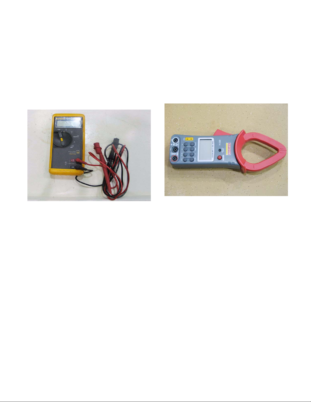
Digital volt ohm meter
Digital volt ohm meters or DVOMs are the most useful
tool to troubleshoot any electrical system. Depending
on the model of DVOM used, DVOMs can measure
Volts, Amps, Ohms and more. DVOMs are a must
when working on circuits with solid state components
(microchips). They have very high impedance, that
means they have very high resistance and pull very little current from the circuit. Use of analog equipment or
test lights will pull enough current to damage the microchips in the circuit. See Figure 2.3.
Inductive amp meter
An inductive amp meter, sometimes referred to as an
“amp clamp” or clamp meter, measures current following through a wire by the magnetic field created around
the wire. Clamp meters are very important when dealing with currents over 10 amps. A DVOM typically can
not measure current over 10 amps. Clamp meters are
also helpful because they can read current in a circuit
without opening it up to hook the meter into the circuit.
See Figure 2.4.
Figure 2.3
When measuring volts, always hook the meter in parallel with the circuit. That means do not disconnect the
component where measuring voltage.
When measuring current the meter must be connected
in series with the component to be measured. That
means opening the circuit and having the circuit go
through the meter.
NOTE: The only exception to this is when us ing
an inductive amp clamp.
When measuring resistance, the component must be
isolated from the circuit.
CAUTION: The meter has it’s own power source
to measure resistance. connecting the meter to
a component that has current going through it
will damage the meter (usually beyond repair).
NOTE: When measuring resistance and there is
no continuity, the meter will read infinity. This is
represented in a few different ways like: OL
(open line) or 1.0 displayed to the far left. Check
the operator’s manual for th e DVOM to see how
it is represented on your meter..
Figure 2.4
Wiring or a schematic diagram
A wiring or a schematic diagram is very important in
troubleshooting a circuit. The diagram shows how the
circuit was designed and what paths the electricity is
suppose to flow.
Fused jumper wires
Fused jumper wires are handy to he lp find b ad groun ds
or to jump across switches for testing purposes.
CAUTION: Only use fused jumper wires. If there
is a short in the circuit, using an unfused jump
could damage components in the circuit further.
Types of circuits
There are three ways a circuit can be wired. They are:
•Series
• Parallel
• Series/parallel
5
Page 10

ELECTRICAL SYSTEM
Series
• Series circuits are wired so that the current has
only one path to follow. See Figure 2.5.
Switch
Bulb
Battery
Figure 2.5
Parallel
Parallel circuits are wired so that current has multiple
paths to follow. See Figure 2.6.
Series/parallel
Series/parallel circuits have some sections wired in
series and some in parallel. See Figure 2.7.
Figure 2.7
Types of failures
There are three types of failures that can occur in an
electrical circuit:
Figure 2.6
1. Shorts
2. Opens
3. Increased resistance
Shorts
A short is when electricity takes a path that it was not
designed to take bypassing a component in the cir cuit.
An common example of a short is the wire that chafed
through. The bare copper will short the circuit when it
touches a ground source.
Opens
An open is when current can not complete its p ath back
to the power source.
A common example of this is a blown fuse.
Increased resistance
Increased resistance is as the name implies, an
increase in resistance.
Arguably the most common electrical failure, and the
hardest to find, it is when there is a loose connectio n or
corrosion. It is not an open because there is some current that can get through, but the increase in resistance
is enough to affect the circuit
6
Page 11
ELECTRICAL SYSTEM
Switches
To test a switch:
1. Remove the switch from the circuit.
2. Set the DVOM to the ohms scale (
3. With the switch in the off position touch one
probe to one of the tabs and the other probe to
the other tab.
4. For a NC switch there should be zero resist ance.
For a NO switch the meter should show an open
circuit.
5. With the probes still attached, turn the switch on.
The readings should reverse, NO should have
zero resistance and a NC switch should indicate
an open circuit.
6. Repeat for all the circuits in the switch
7. If the switch fails in any of the tests, replace the
switch.
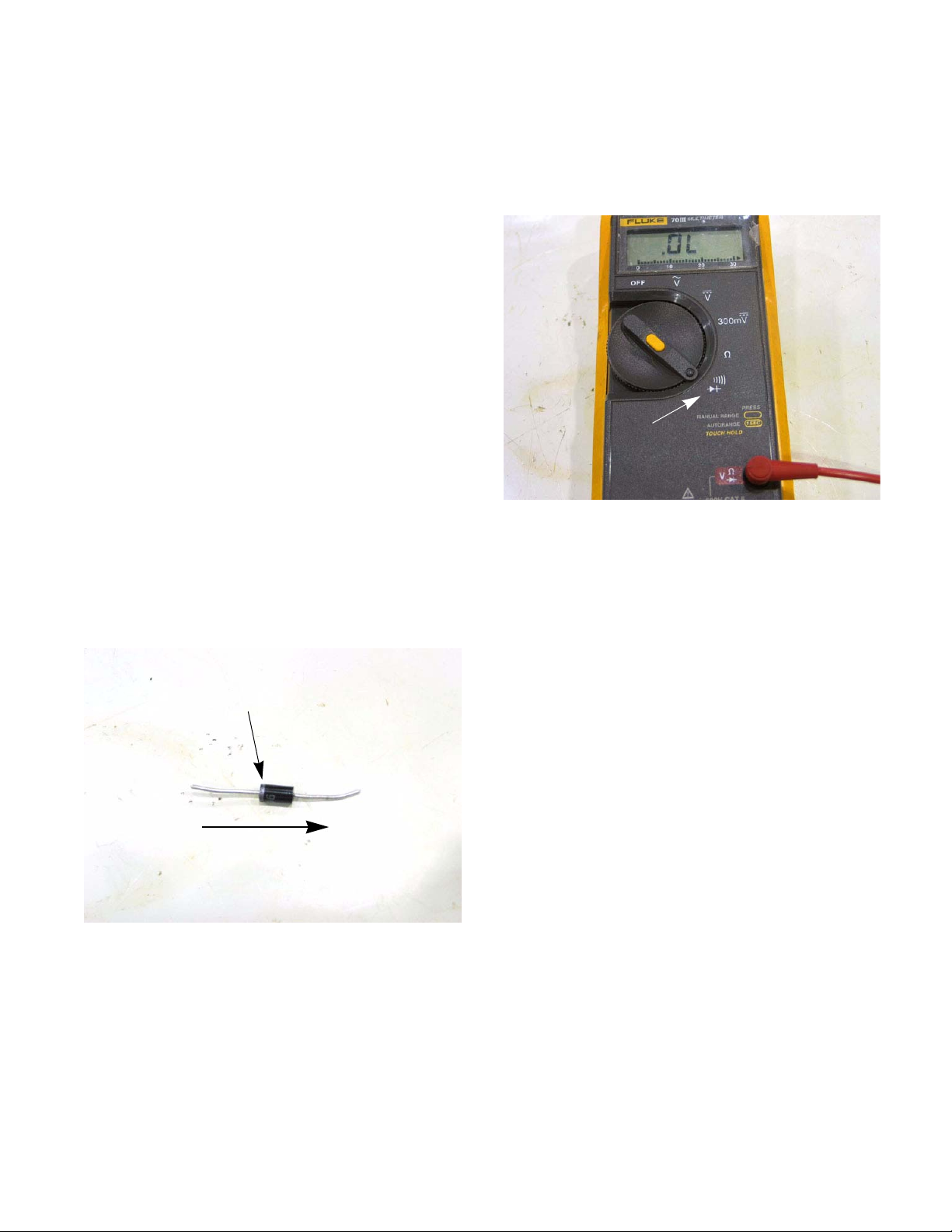
Diodes
A diode acts like a one way valve. They allow current to
flow in only one direction. There will be a band on one
end of the diode. This indicates the negative side o f th e
diode. Most DVOMs have the ability to test a diode.
See Figure 2.8.
Silver band
Ω).
Testing a diode:
1. Isolate the diode in the circuit.
2. Set the DVOM to the diode scale.
See Figure 2.9.
Diode scale
Figure 2.9
NOTE: A diode requires and uses a small
amount of voltage before it allows current to follow through it. When testing a diode the Ohms
(Ω) scale can be used, but it will read resistance
in both directions. One side will be higher then
the other. the reading are hard to interpret without the datasheets of the diode, therefore the
diode scale is the preferred method of testing.
3. Attach the negative lead of the DVOM to the side
of the diode with a band on it.
(-)
electrons flow from the negative to the positive.
Figure 2.8
(+)
4. Place the positive lead on the other side of the
diode.
7
Page 12

ELECTRICAL SYSTEM
5. There should be continuity. See Figure 2.10.
Continuity
Silver band
(-)
Figure 2.10
6. Switch the leads.
7. The meter should indicate no continuity.
See Figure 2.11.
No continuity
(+)
Fuses
Fuses can be visually inspected to indicate they are
bad/blown (a dark spot or the element inside will be in
two pieces). Some times a fuse can be bad and not
show signs of this visually. Any time a fuse is removed
from a circuit, it should be tested for continuity with an
ohm meter before reinstalling. See Figure 2.12.
Figure 2.12
Silver band
(-)
Figure 2.11
8. If the results do not match the above, replace
the diode.
(+)
8
Page 13

ELECTRICAL SYSTEM
Initial trouble shooting
The first step in trouble shooting this mower is to make
sure the circuit breaker is set. To do this, first make
sure the mower is cold (has not been operated for at
least five minutes). Next push the breaker in.
See Figure 2.13.
Safety key
Breaker
Figure 2.13
After assuring the breaker is set and the safety key is in
place, remove the motor cover by following the steps
outlined in Chapter 3: Repair Procedures, and check
the fuse. If the fuse is ok, then troubleshoot the electrical system of this mower by looking at three components:
• The switch box assembly
• The batteries
• The motor
NOTE: Before attempting to trouble shoot this
mower, make sure the batteries are fully
charged.
Next, make sure the safety key is in place. The safet y
key acts as a fulcrum for the switch. With out it, the
switch can not operate. See Figure 2.14.
Safety key
Figure 2.14
9
Page 14

ELECTRICAL SYSTEM
Checking the motor
To test the motor:
1. Remove the motor cover by follo wing the steps
described in Chapter 3: Repair Procedures.
2. Disconnect the motor from the harness.
See Figure 2.15.
Motor connector
Figure 2.15
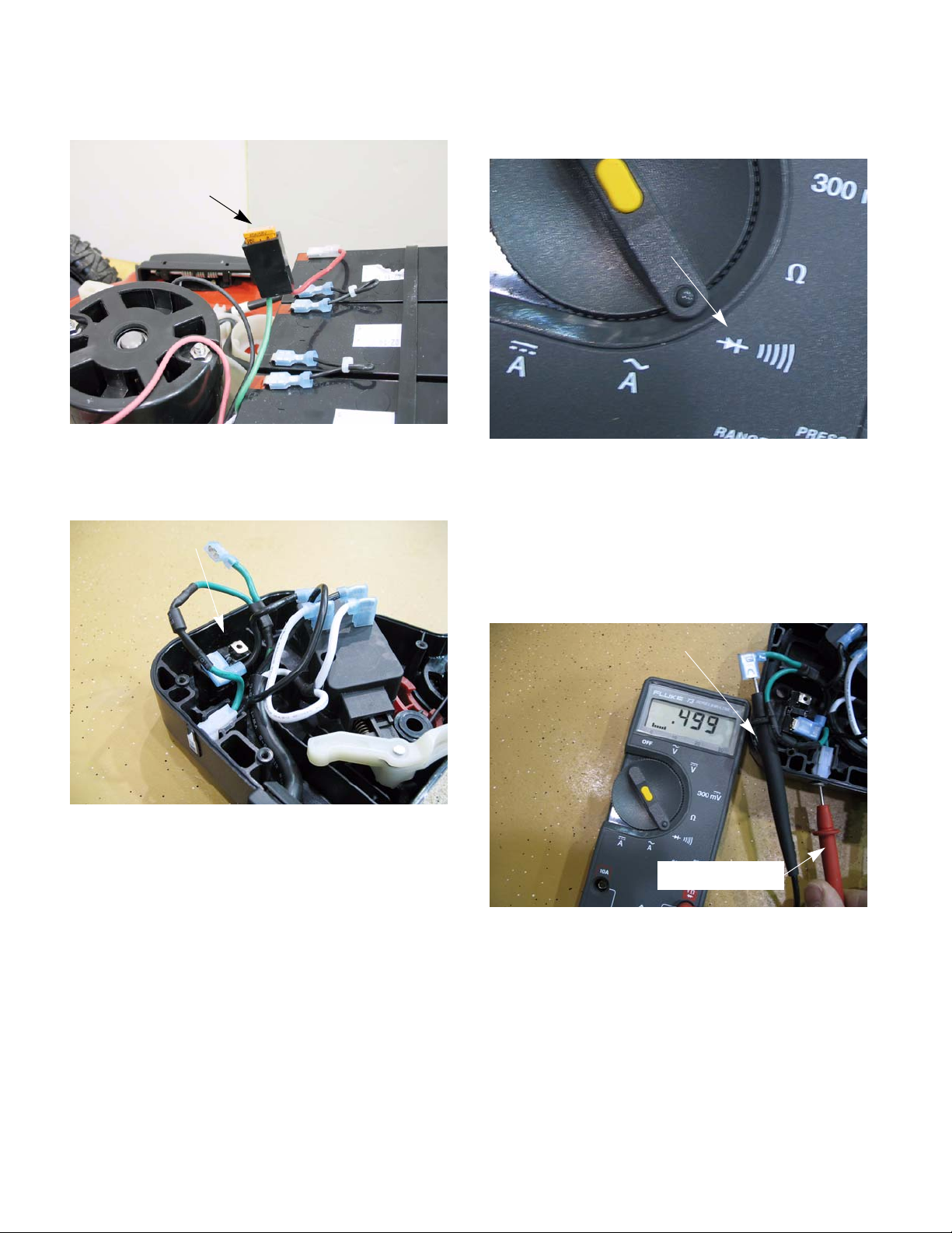
5. The reading on the meter should be within .1
volts of the battery voltage. If it is, the switch box
is working properly and by process of elimination, the motor is the problem.
NOTE: The motor is not serviceable.
NOTE: If the reading is between .1 volt to 5 volts
look for lose or corroded connections.
NOTE: If there is no voltage reading, check the
fuse at the motor before testing further.
See Figure 2.17.
3. Engage the safety bail and hold it in place with a
spring clamp.
4. Connect a volt meter to the two spades in the
harness connector. See Figure 2.16.
Harness connector
Figure 2.16
Figure 2.17
10
Page 15
ELECTRICAL SYSTEM
Testing the switch box and harness
IMPORTANT: If the mower is within the warranty
period, Do Not open the switch box. Replace the
entire switch box for warranty. Outside of warranty, the switch box is serviceable.
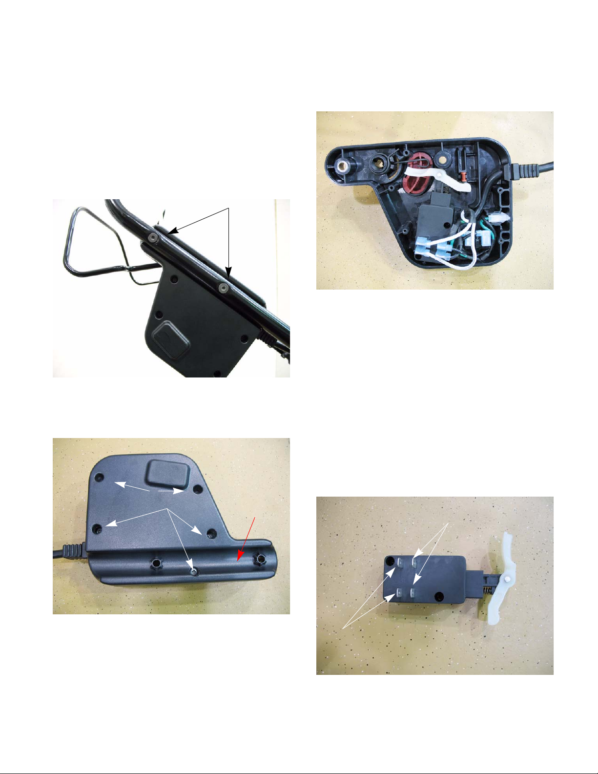
1. To test the components inside the switch box,
remove and open the switch box by:
1a. Remove the two mounting screws with a T-
25 torx driver. See Figure 2.18.
Remove these screws
1c. Carefully separate the halves of the switch
box. Remove the side that fits against the
handle bar.. See Figure 2.20.
Figure 2.20
2. Test the switch.
NOTE: The switch is a double pole single throw
switch. That means that it controls two separate
circuits at the same time.
Figure 2.18
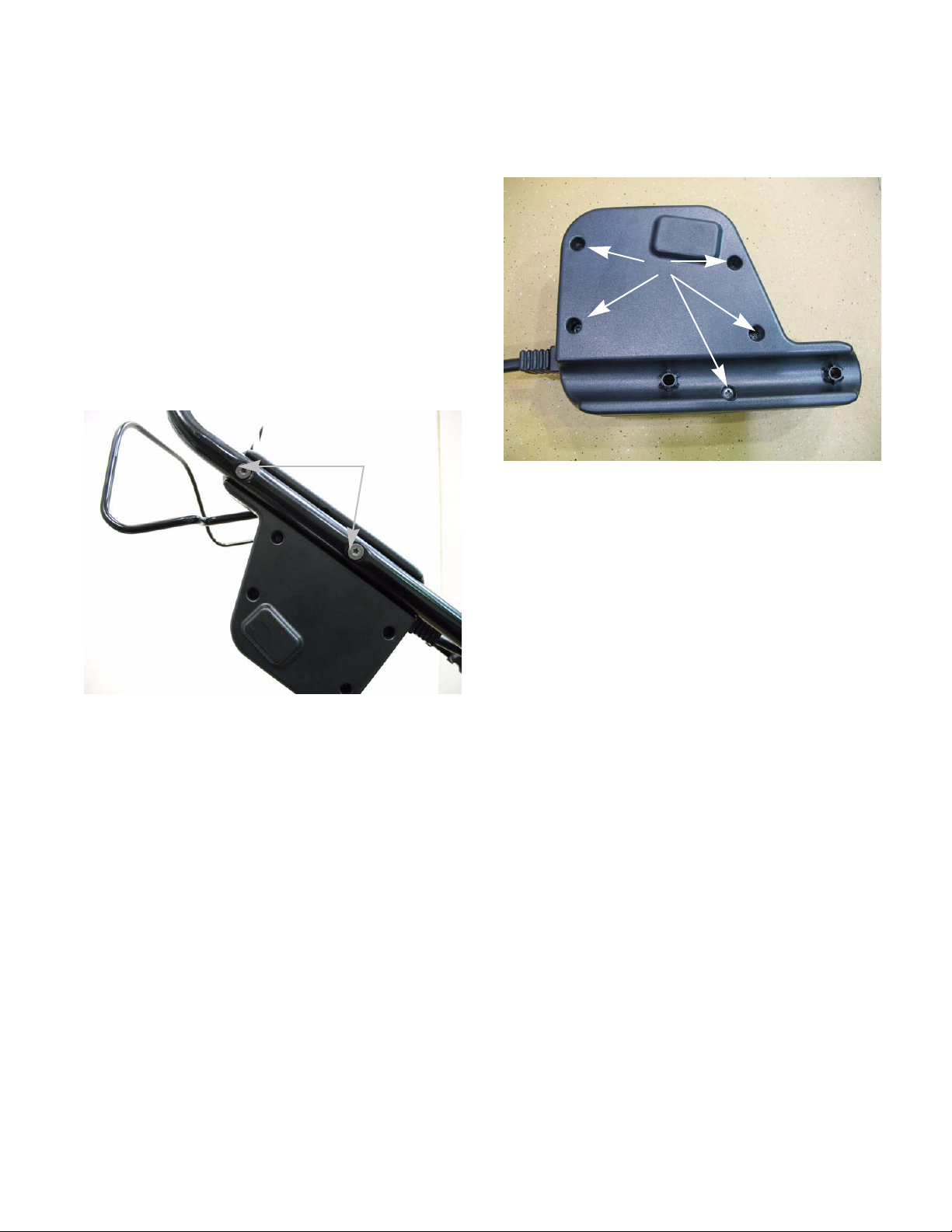
1b. Remove the five screws that hold the switch
assembly together. See Figure 2.19.
Remove these
screws
Figure 2.19
Handle bar
grove
2a. Mark and disconnect all four wires.
NOTE: Mark the wires to ensure they go back on
the proper spades. If the wires are put on wrong
the mower will not work properly, if at all.
2b. Test each circuit separately.
NOTE: Unlike most MTD switches, the terminals
that are in-line with each other, edge to edge,
are in the same circuit. See Figure 2.21.
Circuit 2
Circuit 1
11
Figure 2.21
Page 16

ELECTRICAL SYSTEM
2c. Circuit 1 is a normally closed circuit. That
means there should be continuity through
that circuit when the switch is at rest.
2d. To test that part of the switch, attach a
DVOM to the circuit. Set the meter to the
Ohms or “Ω
read zero ohms. See Figure 2.22.
2e. With the DVOM still attached, press in the
switch. The meter should read infinity.
See Figure 2.23.
” scale. The meter should
Figure 2.22
2f. Circuit 2 is a normally open circuit. That
means there should not be continuity
through that circuit when the switch is at
rest.
2g. To test that part of the switch, attach a
DVOM to the circuit. Set the meter to the
Ohms or “Ω” scale
read infinity. See Figure 2.24.
Figure 2.24
2h. With the DVOM still attached, press in the
switch. The meter should read zero or
near zero resistance. See Figure 2.25.
. The meter should
Figure 2.23
Figure 2.25
2i. If the switch has any reading different than
what is described above, replace the
switch.
2j. Reconnect the wires to the switch. Make
sure the wires are attached to the proper
terminals.
12
Page 17

ELECTRICAL SYSTEM
3. Test the circuit breaker.
NOTE: Make sure the circuit breaker is cool and
pressed in before testing it.
3a. Disconnect the two wires from the circuit
breaker. See Figure 2.26.
Figure 2.26
Circuit
breaker
4. Test the diode.
NOTE: There is a diode between the charger
jack and the circuit breaker. It has two jobs. First
it protects the batteries from a short in the
charger jack, like a child inserting something into
the charger jack. Secondly it helps to protect the
charger from a back-feed when the mower is
operated with the charger plugged in.
See Figure 2.28.
Diode
Charger
jack
3b. Attach a DVOM to the circuit breaker. Set
the meter to the Ohms or “Ω” scale
should read zero or near zero Ohms.
See Figure 2.27.
Figure 2.27
3c. If the meter reads anything over 0.1 Ohms,
replace the circuit breaker.
. It
Figure 2.28
CAUTION: Do not operate the mower with the
charger plugged in.
NOTE: An open diode will prevent the batteries
from charging. A shorted diode could allow the
batteries to short out or damage the charger.
4a. When testing the diode, make sure the
charger or any thing else is not plugged
into the charger jack.
13
Page 18
ELECTRICAL SYSTEM
4b. Remove the fuse. See Figure 2.29.
Fuse
Figure 2.29
4c. Disconnect the circuit breaker.
See Figure 2.30.
Unplug the circuit breaker
4d. Set the DVOM to the diode test scale.
See Figure 2.31.
Diode test scale
Figure 2.31
4e. Insert the positive probe of the DVOM into
the port of the charger jack that has the
green wire.
4f. Insert the negative probe into the connector
of the wire disconnected from the circuit
breaker. See Figure 2.32.
Figure 2.30
NOTE: By unplugging the fuse and circuit
breaker, the diode has been isolated. It is not
necessary to remove the heat shrink tubing from
the diode to test it.
NOTE: Diodes can be tested by using the Ohms
or “Ω” scale of a DVOM, but because of the way
diodes are constructed this is not an accurate
way to test them. When testing diode using the
“Ω” scale, it will read continuity in both directions. One direction will be high resistance and
the other direction will be a relatively low resistance. These readings will not tell you if the
diode is leaking.
Negative probe
Positive probe
Figure 2.32
14
Page 19

ELECTRICAL SYSTEM
4g. The DVOM should read less than 1 Ohm.
4h. Reverse the leads. See Figure 2.33.
Positive probe
Negative probe
Figure 2.33
4i. The DVOM should read open line or “OL”.
4j. If either reading varies from the values listed
above, replace the harness.
5. If all the components in the switch box are working properly and battery voltage still does not get
to the motor, replace the harness.
Batteries and charger
Batteries
Before an electrical system can be diagnosed, the bat-
tery must be fully charged and in good working order.
Charging the battery
NOTE: Batteries on most modern outdoor power
equipment are 12 volts. This mower uses a bank
of four, sealed 12 volt lead-acid batteries. The
four act as one and should be looked at and
treated as one big battery .
IMPORTANT: Do not replace individual batteries. Replace all four batteries with new batteries
that are the same age. This will prevent weaker
batteries overworking the strong batteries and
prolong the life of all of them.
IMPORTANT: The voltage of the battery bank is
over 48 volts for a fully charged battery bank. To
ensure that the batteries in the battery bank are
evenly charged, only use the charger that came
with the mower.
To test the battery pack:
CAUTION: The mower must run in order to test
the battery pack, move the mower to a safe location when operating it.
NOTE: The battery charger will charge the batteries to a voltage higher than then can maintain
on their own. Once the charger is unplugged, the
battery pack will start to bleed of excess voltage.
Allow 10 minutes for the batteries to normalize
after unplugging from a charger before measuring voltage.
1. Remove the motor cover by following the steps
described in Chapter 3: Repair Proc edures.
2. Attach a DVOM to the harness by back probing
where the connection at the battery pack and
place the DVOM in a secure location.
NOTE: Make a note of the battery voltage at this
point. A fully charged battery will read between
50.4 - 54.0 volts.
15
Page 20

ELECTRICAL SYSTEM
3. Attach a digital amp clamp to either one of the
motor leads (the current will be positive or negative depending on which LED is used).
Figure 2.34
4. Start the mower and run it for 10 seconds then
read both meters. See Figure 2.35.
NOTE: Do not operate the mow er in g r ass wh en
testing the battery pack. The measurements are
meant to be take with the blade as the only load
on the motor.
Interpreting the results
Table 1:
Voltage Current Possible reasons
>47.0 < 9.5 Normal readings
>47.0 >9.5 High load on
motor, a short in
the harness or
motor worn out.
Check for grass
build up underneath the deck.
44.0-47.0 < 9.5 Battery pack low
or one battery
going bad, charge
the battery pack
and retest.
< 44.0 < 9.5 Battery pack is
bad.
< 44.0 < 44.0 short in system
Figure 2.35
16
Page 21

ELECTRICAL SYSTEM
Battery charger
The batteries in the battery pack are wired in series
resulting in a 48 volt system. The battery charger for
this mower has an output of 54.5 volts so that the
whole battery pack is charged at one time.
To test the battery charger:
1. Disconnect the charger from the mower.
2. Plug the charger to an appropriate AC outlet.
3. Set a DVOM to the volts DC scale.
4. Attach the DVOM to the charger jack, the red (+)
lead to the pin next to the clip and the black(-)
lead on the other pin. See Figure 2.36.
Clip
Battery indicator
This mower is equipped with a battery level indicator.
The indicator has five LEDs, the n umber of LEDs that
are lit is an indication of the voltage level of the battery.
It will only light up when the mower is in operation.
To test the battery indicator, a cheap tester can be
made from parts around the shop or buying the parts
from an electronic supply store. The components
needed are:
•10K Ω variable resistor.
NOTE: A potentiometer, rheostat or a dash light
dimmer switch from a car can be used as a variable resistor. If using a rheostat or a potentiometer, multi-turn works best.
• A fuse holder with a small fuse.
NOTE: A 1 amp fuse is recommended.
• 1 alligator clips.
• 1 female spade connector.
• A jumper wire (to be used with the tester).
•Wire.
Figure 2.36
5. The meter should read 54.5 volts (+
the readings do not match this, replace the
charger.
NOTE: This charger is a two stage charger. The
initial stage will charge a battery pack at a voltage at a voltage of 57.6 volts (+
stage is used when the battery pack is fully discharged. When the battery pack is charged, the
charger will switch to a float charge mode,
charging the battery pack at a voltage of 54.5
volts (+
) .5 volts.
) .5 volts. this
To build the tester:
1. Solder a one lead of the fuse holder to the center
tap pin of the variable resistor. See Figure 2.37.
The package of the variable resistor will have
a schematic drawing. In the drawing this is
the center tap.
) .5 volts. If
Figure 2.37
2. Solder an additional length of wire to the other
lead of the of the fuse holder.
NOTE: The over all length of the additional wire
and the fuse holder should be at least 12”.
3. Crimp the female spade connector onto the end
of the new fuse holder lead.
17
Page 22

ELECTRICAL SYSTEM
4. Attach an alligator clip on to a piece of wire, at
least 12” in length.
5. Solder the piece of wire onto one of the other
two pins on the variable resistor. See Figure
2.38.
Alligator clip
Female spade
10K potentiometer
Fuse holder
Figure 2.38
Testing the battery indicator
NOTE: The battery pack should be fully charged
to test the battery indicator.
1. Disconnect the charger from the mower.
2. Remove the motor cover by following the steps
described in Chapter 3: Repair Procedures.
3. Unplug the wires from the battery indicator.
NOTE: The wire connectors are two different
sizes to help prevent getting them crossed when
plugging them in. See Figure 2.39.
Small tab is positive
Big tab is negative
Figure 2.39
4. Disconnect the battery pack.
5. Attach the spade end of the tester to the positive
tab of the indicator.
6. Attach the other end of the tester to the positive
post of the battery pack.
7. Attach one end of the jumper wire to the negative tab of the indicator and the other end to the
negative post of the battery pack.
18
Page 23

ELECTRICAL SYSTEM
8. Attach the positive lead of a DVOM to the positive (smaller) tab of the indicator. See Figure
2.40.
Positive lead of
DVOM
Tester leads
Figure 2.40
9. Attach the negative lead of the DVOM to the
negative post of the battery pack.
10. Set the DVOM to the DC volts scale and place it
close to the indicator so that both can be seen at
the same time.
12. Compare the results to Table 2.
Table 2:
LED
LED 1LED 2LED 3LED 4LED
operation
Voltage
green green green green red
52 - 47.9 ON ON ON ON OFF
47.9-
OFFONONONOFF
46.7
46.7-
OFF OFF ON ON OFF
45.2
45.2-
OFF OFF OFF ON OFF
40.4
40.4-28 OFF OFF OFF OFF ON
NOTE: If the results do not match the above
table, replace the indicator. If they do match the
above results, check the harness.
Returning to service
5
11. Slowly turn the variable resistor and note the
reading on the DVOM when the different LEDs
light up or go out. See Figure 2.41.
Monitor LEDs and DVOM
Figure 2.41
After diagnosing and repairing any fault in an electrical
circuit and any other repairs needed, the following
steps should be taken:
1. Test run the machine to verify that the condition
has been fix.
2. Cycle the circuit at least ten times.
3. Allow the machine to cool down for a couple of
hours.
4. Re-test the machine to verify the co ndition does
not re-appear.
5. If the condition does not re-appear, return the
machine back to service.
19
Page 24

ELECTRICAL SYSTEM
System schematic drawing
Circuit
Breaker
20
Page 25

CHAPTER 3: REPAIR PROCEDURES
REPAIR PROCEDURES
General safety warning
Whenever working on a cordless lawn mower, remove
the safety key. Only leave the key in if it is needed to
perform a test.
CAUTION: Use caution while working around
this lawn mower. A cordless lawn mower may
start unexpectedly.
Blades
The condition of the blades will greatly effect the quality
of the cut.
The blades should be sharpened and balanced after
every hour of cutting, depending on local conditions. A
dull blade tears the grass instead of cutting it. Torn
grass blades leaves a rough look and makes the grass
vulnerable to diseases.
Blades need to be examined for damage before sharpening. Blades must be balanced after sharpening to
reduce the vibrations felt from the deck.
Bent blades are a sign of a blade impact. When a bent
blade is found, the blades must be replaced and the
motor inspected for a bent shaft and cracked motor
mount.
To replace the blade:
WARNING: When removing the cutting blade for
sharpening or replacement, protect your hands
with a pair of heavy gloves or use a heavy rag to
hold the blade.
1. Disconnect the power supply to the mower and
turn the mower on its side.
2. Block the blade to prevent it from turning when
the bolt is removed. See Figure 3.1.
NOTE: The blade can be blocked using a piece
of wood between the blade and the mower deck
or use of a commercially available blade locking
device.
Blade holder
The cutting deck on this mower is mounted with a slight
rake, meaning that the front of the deck is a 1/4” - 3/8”
lower than the rear of the deck. T his is very important
to get the proper air flow in the deck so that the blades
can make the grass blades stand up to get cut.
The air flow in the cutting deck is generated by the
spinning blades. If the blades are mounted upside
down, the air flow will be reversed pushing the grass
down instead of standing up.
NOTE: Blades that are mounted upside down,
increase the risk of blade damage from struck
objects.
NOTE: The blade also act s as the cooling fan for
the motor. The motor will over heat if the blade is
mounted upside.
Figure 3.1
NOTE: The blade locking tool pictured above is
available through MTD parts. The part number is
BB-100.
21
Page 26

REPAIR PROCEDURES
3. Loosen and remove the blade bolt, locking plate,
and blade using a 24 mm wrench. See Figure
3.2.
24 mm wrench
Figure 3.2
NOTE: Make certain to replace the parts in the
exact order in which they were removed. When
installing the cutting blade, be sure it is installed
with the curved ends pointing towards the
mower deck and not towards the ground. See
Figure 3.3.
4. The blade can be sharpened with a file or on a
grinding wheel.
NOTE: To properly sharpen the cutting blades,
remove equal amounts of metal from both ends
of the blades along the cutting edges, parallel to
the trailing edge, at a 25° to 30° angle.
WARNING: An unbalanced blade will cause
excessive vibration when rotating at high
speeds. It may cause damage to mower and
could break causing personal injury.
5. Place the cutting blade, locking plate, and blade
bolt on the motor shaft.
Figure 3.3
6. Tighten the blade bolt to a torque of 170-220 inlbs (19 - 25Nm).
WARNING: The blade hardware is not only used
to attach the blade assembly, but is also an insulated safety device and should never be altered
in any way. If replacement is necessary, use
original equipment parts.
7. Test run the mower before returning to service.
22
Page 27
REPAIR PROCEDURES
Switch box assembly
The switch box assembly is located on the upper handle bar. The switch and circuit breaker are housed
inside of it. To service the switch box assembly:
NOTE: Opening the switch box assembly will
void the warranty on this mower. For warranty
repairs, replace the switch box and harness as
an assembly.
1. Remove the safety key.
2. Slide the safety bail out of the switch box assembly.
3. Remove the two mounting screws usin g a T-27
Torx driver. See Figure 3.4.
Mounting screws
5. Remove the five screws holding the housing
together using a #2 phillips screwdriver. See Figure 3.5.
Remove screws
Figure 3.5
6. Separate the housing to reach the internal components.
NOTE: The test procedures for the components
of the switch box are in Chapter 2 Electrical system.
Figure 3.4
4. Unhook the harness from the clips on the handle
bar.
7. Install the switch box by following the above
steps in reverse order.
8. Test run the mower before returning it to service.
23
Page 28

REPAIR PROCEDURES
To replace the switch box:
1. Remove the safety key.
2. Slide the safety bail out of the switch box assembly.
3. Remove the motor cover by follo wing the steps
describe in the motor section of this chapter.
NOTE: For safety reasons it is a good idea to
remove the fuse whenever the motor cover is
removed.
4. Disconnect the battery pack and the motor.. See
Figure 3.7.
Motor connector
Battery
connection points
5. Remove the two mounting screws using a T-27
Torx driver. See Figure 3.8.
Mounting screws
Figure 3.8
6. Unhook the harness from the clips on the handle
bar.
7. Install the switch box assembly by following the
above steps in reverse order.
Figure 3.7
8. Test run the mower before returning to service.
24
Page 29

REPAIR PROCEDURES
Motor
The motor on this mower is a DC permanent magnet
motor. It is not serviceable. The test procedures for this
motor are covered in chapter 2 Electrical system.
To replace the motor:
1. Remove the safety key.
2. Remove the motor cover by:
2a. Place a flat head screwdriver into one of the
four slots in the cover. See Figure 3.9.
Push in tab
with a flat head screwdriver
3. Remove the blade by following the steps
described in the blade section of this chapter.
4. Remove the fan and blade hub from the motor
shaft. See Figure 3.11.
Blade hub
Figure 3.11
5. Unplug the motor. See Figure 3.12.
Figure 3.9
2b. Press in the tab while lifting on the cover.
Repeat steps 2a and 2b on the other slots.
NOTE: For safety reasons it is a good idea to
remove the fuse when ever the motor cover is
removed. See Figure 3.10.
Motor connector
Figure 3.12
Figure 3.10
25
Page 30

REPAIR PROCEDURES
6. Remove the four mounting screws. See Figure
3.13.
Mounting screws
Figure 3.13
7. Install the motor by following the above steps in
reverse order.
8. Test run the mower before returning it to service.
Motor mount
To replace th e mo to r mo u nt :
1. Remove the safety key.
2. Remove the motor by following the steps
described in the previous section of this manual.
3. Remove the three mounting screws using T-40
torx driver. See Figure 3.14.
Mounting screws
Figure 3.14
4. Remove the motor mount from the deck of the
mower.
5. Install the motor mount by following the above
steps in reverse order.
NOTE: tighten the motor mount screws to a
torque of 170-200 in-lbs (19 - 22.5 Nm).
6. Test run the mower before returning to service.
26
 Loading...