

Page 1
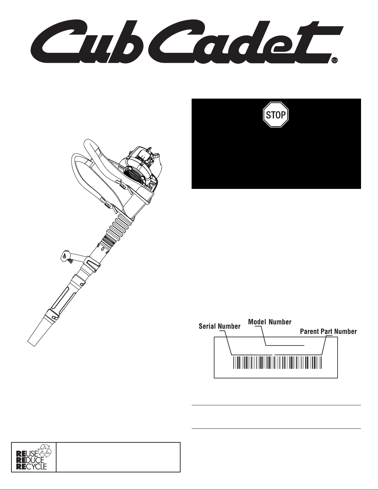
Operator’s Manual
2-Cycle Backpack Blower
BP226
P/N 769-04595 P00 (01/09)
For service call 1-877-282-8684, or 1-800-668-1238 in Canada to
obtain a list of authorized service dealers near you. For more details
about your unit, visit our website at www.cubcadet.com or
www.cubcadet.ca.
DO NOT RETURN THE UNIT TO THE RETAILER. PROOF OF
PURCHASE WILL BE REQUIRED FOR WARRANTY SERVICE.
THIS PRODUCT IS COVERED BY ONE OR MORE U.S. PATENTS.
OTHER PATENTS PENDING.
Service on this unit both within and after the warranty period should be
performed only by an authorized and approved service dealer.
Copy the serial number here:
Copy the model and parent part number here:
All information, illustrations, and specifications in this manual are based on
the latest product information available at the time of printing. We reserve
the right to make changes at any time without notice.
Copyright© 2009 MTD SOUTHWEST INC, All Rights Reserved.
TABLE OF CONTENTS
Service Information . . . . . . . . . . . . . . . . . . . . . . . . . . . . . . . . . . . .1
Rules for Safe Operation . . . . . . . . . . . . . . . . . . . . . . . . . . . . . . . .2
Know Your Unit . . . . . . . . . . . . . . . . . . . . . . . . . . . . . . . . . . . . . . .5
Assembly Instructions . . . . . . . . . . . . . . . . . . . . . . . . . . . . . . . . . .5
Oil and Fuel . . . . . . . . . . . . . . . . . . . . . . . . . . . . . . . . . . . . . . . . . .6
Starting/Stopping Instructions . . . . . . . . . . . . . . . . . . . . . . . . . . . .6
Operating Instructions . . . . . . . . . . . . . . . . . . . . . . . . . . . . . . . . . .6
Maintenance and Repair Instructions . . . . . . . . . . . . . . . . . . . . . .7
Cleaning and Storage . . . . . . . . . . . . . . . . . . . . . . . . . . . . . . . . . . .7
Troubleshooting . . . . . . . . . . . . . . . . . . . . . . . . . . . . . . . . . . . . . . .8
Specifications . . . . . . . . . . . . . . . . . . . . . . . . . . . . . . . . . . . . . . . . .8
Warranty Information . . . . . . . . . . . . . . . . . . . . . . . . . . . . . . . . .E12
SAVE THESE INSTRUCTIONS
Before beginning, locate the unit’s model plate. It lists the model and
serial numbers of your unit. Refer to the sample plate below and
copy the information for future reference.
In an effort to reduce the impact on the forests,
and reduce carbon and greenhouse gas
emissions, MTD is using less paper by reducing
the text size of this manual.
DO NOT RETURN
THIS PRODUCT
For Assistance please call 1-877-282-8684 (U.S.) or
1-800-668-1238 (Canada)
or visit www.cubcadet.com / www.cubcadet.ca
MODEL :
S/N :
ITEM :
Page 2
2
• Add fuel in a clean, well-ventilated area outdoors where there are
no sparks or flames. Slowly remove the fuel cap only after
stopping engine. Do not smoke while fueling. Wipe up any spilled
fuel from the unit immediately.
• Avoid creating a source of ignition for spilled fuel. Do not start
the engine until fuel vapors dissipate.
• Move the unit at least 30 feet (9.1 m) from the fueling source and site
before starting the engine. Do not smoke. Keep sparks and open
flames away from the area while adding fuel or operating the unit.
WHILE OPERATING
• Never start or run the unit inside a closed room or building.
Breathing exhaust fumes can kill. Operate this unit only in a wellventilated outdoor area.
• Wear safety glasses or goggles that are marked as meeting ANSI
Z87.1–1989 standards and are marked as such. Wear ear/hearing
protection when operating this unit.
• Never run the unit without the the proper equipment attached.
• To reduce the risk of hearing loss associated with sound level(s),
always wear ear/hearing protection when operating this unit.
• Wear heavy long pants, boots, gloves, and a long sleeve shirt. Do
not wear loose clothing, jewelery, short pants, sandals or go
barefoot. Secure hair above shoulder level.
• To avoid static electricity shock, do not wear rubber gloves or
any other insulated gloves while operating this unit.
• Use the unit only in daylight or good artificial light.
• Keep outside surfaces free from oil and fuel.
• Avoid accidental starting. Be in the starting position whenever
pulling the starter rope. The operator and unit must be in a stable
position while starting. Refer to Starting/Stopping Instructions.
READ ALL INSTRUCTIONS BEFORE OPERATING
• Read the instructions carefully. Be familiar with the controls and
proper use of the unit.
• Read this operating instruction manual carefully. Be thoroughly
familiar with the controls and the proper use of the equipment.
Know how to stop the unit and disengage the controls quickly.
• Do not operate this unit when tired, ill, or under the influence of
alcohol, drugs, or medication.
• Never allow children to operate the equipment. Never allow
adults unfamiliar with the instructions to use the unit. Never allow
adults to operate the equipment without proper instruction.
• All blower tubes must be installed properly before operating the
unit.
SPECIAL SAFETY WARNINGS FOR GAS ENGINES
• Store fuel only in containers specifically designed and approved
for the storage of such materials.
• Always stop the engine and allow it to cool before filling the fuel tank.
Never remove the cap of the fuel tank, or add fuel, when the engine
is hot. Never operate the unit without the fuel cap securely in place.
Loosen the fuel tank cap slowly to relieve any pressure in the tank.
• IMPORTANT SAFETY INSTRUCTIONS •
Read the Operator’s Manual and follow all warnings and safety instructions. Failure to do so can result in serious injury to the
operator and/or bystanders.
FOR QUESTIONS, CALL 1-877-282-8684 IN U.S. OR 1-800-668-1238 in CANADA
The purpose of safety symbols is to attract your attention to possible
dangers. The safety symbols, and their explanations, deserve your
careful attention and understanding. The safety warnings do not by
themselves eliminate any danger. The instructions or warnings they
give are not substitutes for proper accident prevention measures.
NOTE: Advises you of information or instructions vital to the
operation or maintenance of the equipment.
SAFETY ALERT:
Indicates danger, warning or
caution. Attention is required in order to avoid serious
personal injury. May be used in conjunction with other
symbols or pictographs.
DANGER:
Failure to obey a safety warning will result
in serious injury to yourself or to others. Always follow
the safety precautions to reduce the risk of fire, electric
shock and personal injury.
WARNING:
Failure to obey a safety warning can
result in injury to yourself and others. Always follow the
safety precautions to reduce the risk of fire, electric
shock and personal injury.
CAUTION:
Failure to obey a safety warning may
result in property damage or personal injury to yourself
or to others. Always follow the safety precautions to
reduce the risk of fire, electric shock and personal injury.
RULES FOR SAFE OPERATION
SYMBOL MEANING
WARNING:
When using the unit, you must follow the
safety rules. Please read these instructions before operating
the unit in order to ensure the safety of the operator and any
bystanders. Please keep these instructions for later use.
WARNING:
Gasoline is highly flammable, and its
vapors can explode if ignited. Take the following
precautions:
SPARK ARRESTOR NOTE
NOTE: For users on U.S. Forest Land and in the states of
California, Maine, Oregon and Washington. All U.S. Forest Land
and the state of California (Public Resources Codes 4442 and
4443), Oregon and Washington require, by law that certain internal
combustion engines operated on forest brush and/or grass-covered
areas be equipped with a spark arrestor, maintained in effective
working order, or the engine be constructed, equipped and
maintained for the prevention of fire. Check with your state or local
authorities for regulations pertaining to these requirements. Failure
to follow these requirements could subject you to liability or a fine.
This unit is factory equipped with a spark arrestor. If it requires
replacement, ask your LOCAL SERVICE DEALER to install the
Accessory Part #753-05945 Muffler Assembly.
CALIFORNIA PROPOSITION 65 WARNING
WARNING
THE ENGINE EXHAUST FROM THIS PRODUCT CONTAINS
CHEMICALS KNOWN TO THE STATE OF CALIFORNIA TO
CAUSE CANCER, BIRTH DEFECTS OR OTHER
REPRODUCTIVE HARM.
Page 3

3
RULES FOR SAFE OPERATION
• Do not set unit on any surface except a clean, hard area while
engine is running. Debris such as gravel, sand, dust, grass, etc.
could be picked up by the air intake and thrown out by the
discharge opening, damaging unit, property, or causing serious
injury to bystanders or operator.
• Use the right tool. Only use this tool for its intended purpose.
• Do not force unit. It will do the job better and with less likelihood
of injury at a rate for which it was designed.
• Do not overreach or use from unstable surfaces such as ladders,
trees, steep slopes, rooftops, etc. Always keep proper footing
and balance.
• Always hold the unit with a firm grip when operating.
• Keep hands, face, and feet away from all moving parts. Do not
touch or try to stop the impeller when it is rotating. Do not
operate without guards in place.
• Do not put any object into openings. Do not use with any
opening blocked; keep free of dirt, debris, and anything that may
reduce the air flow.
• Do not touch the engine or muffler. These parts get extremely
hot from operation, even after the unit is turned off.
• Do not operate the engine faster than the speed needed to do
the job. Do not run the engine at high speed when not in use.
• Always stop the engine when operation is delayed or when
walking from one location to another.
• Stop the engine for maintenance, repair, to install or remove the
blower tubes. The unit must be stopped and the impeller no
longer turning to avoid contact with the rotating blades.
• If you strike or come into contact with a foreign object, stop the
engine immediately and check for damage. Do not operate
before repairing damage. Do not operate the unit with loose or
damaged parts.
• Use only replacement parts recommended for this tool that are
sold by a Cub Cadet outlet. Use of any replacement parts
purchased elsewhere may be hazardous, and will also void your
warranty.
• Never use this unit for spreading chemicals, fertilizers or other
substances which may contain toxic materials.
• To reduce fire hazard, replace faulty muffler and spark arrestor.
Keep the engine and muffler free from grass, leaves, excessive
grease or carbon build up.
• Turn the engine off and disconnect the spark plug for
maintenance or repair.
• Never point the blower or blowing debris in the direction of
people, animals, or in the direction of windows. Always direct the
blowing debris away from people, animals, and windows. Use
extra caution when blowing debris near solid objects such as
trees, automobiles, walls, etc.
OTHER SAFETY WARNINGS
• Always disconnect the spark plug before performing
maintenance or accessing movable parts. See Replacing the
Spark Plug.
• Never store the unit, with fuel in the tank, inside a building where
fumes may reach an open flame (pilot lights, etc.) or sparks
(switches, electrical motors, etc.).
• Allow the engine to cool before storing or transporting. Be sure
to secure the unit while transporting.
• Store the unit in a dry place, secured, or at a height to prevent
unauthorized use or damage. Keep out of the reach of children.
• Never douse or squirt the unit with water or any other liquid.
Keep handles dry, clean, and free from debris. Clean after each
use, see Cleaning and Storage instructions.
• Keep these instructions. Refer to them often and use them to
instruct other users. If you loan this unit to others, also loan
these instructions to them.
SPECIAL NOTE: Exposure to vibrations through prolonged use of
gasoline powered hand tools could cause blood vessel or nerve
damage in the fingers, hands, and joints of people prone to
circulation disorders or abnormal swelling. Prolonged use in cold
weather has been linked to blood vessel damage in otherwise
healthy people. If symptoms occur such as numbness, pain, loss
of strength, change in skin color or texture, or loss of feeling in the
fingers, hands or joints, discontinue use of this tool and seek
medical attention. A reduced vibration system does not guarantee
avoidance of these problems. Users who operate power tools on a
regular basis must closely monitor their physical condition and the
condition of this tool.
SAVE THESE INSTRUCTIONS
Page 4
4
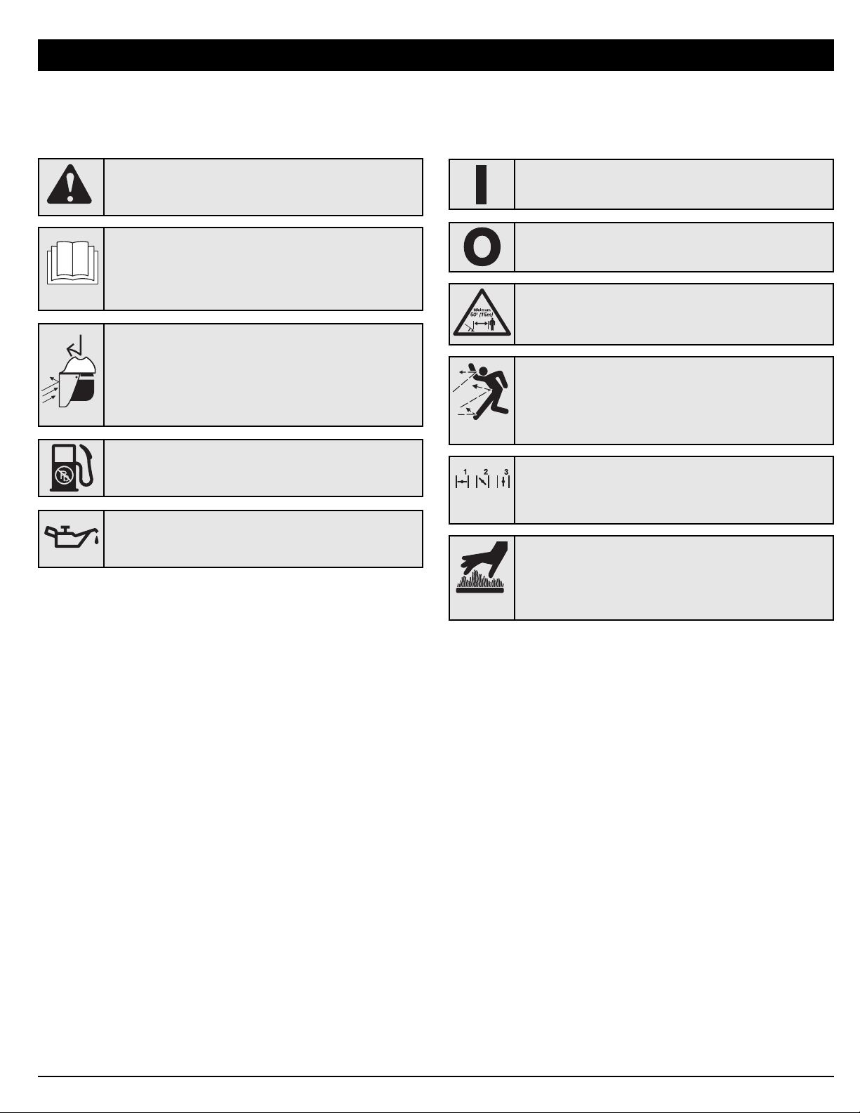
• SAFETY AND INTERNATIONAL SYMBOLS •
This operator's manual describes safety and international symbols and pictographs that may appear on this product. Read the operator's
manual for complete safety, assembly, operating, maintenance,` and repair information.
RULES FOR SAFE OPERATION
• READ OPERATOR'S MANUAL
WARNING: Read the operator’s manual(s) and
follow all warnings and safety instructions. Failure to
do so can result in serious injury to the operator
and/or bystanders.
• KEEP BYSTANDERS AWAY
WARNING:
Keep all bystanders, especially children
and pets, at least 50 feet (15 m.) from the operating area.
SYMBOL MEANING
• THROWN OBJECTS CAN CAUSE SEVERE INJURY
WARNING: Keep clear of blower outlet. Never
point the blower at yourself or others. Objects can
be thrown from blower. Do not operate unit without
proper attachments and guards in place.
• SAFETY ALERT SYMBOL
Indicates danger, warning or caution. May be used in
conjunction with other symbols or pictographs.
SYMBOL MEANING
• WEAR EYE AND HEARING PROTECTION
WARNING: Thrown objects and loud noise can
cause severe eye injury and hearing loss. Wear eye
protection meeting ANSI Z87.1–1989 standards and
ear protection when operating this unit. Use a full
face shield when needed.
•OIL
Refer to operator’s manual for the proper type of oil.
• UNLEADED FUEL
Always use clean, fresh unleaded fuel.
• ON/OFF STOP CONTROL
OFF or STOP
• ON/OFF STOP CONTROL
ON / START / RUN
• HOT SURFACE
WARNING: Do not touch a hot surface. You may
get burned. These parts get extremely hot from
operation. They remain hot for a short time after the
unit is turned off.
• CHOKE CONTROL
1. • FULL choke position
2. • PARTIAL choke position
3. • RUN choke position
Page 5
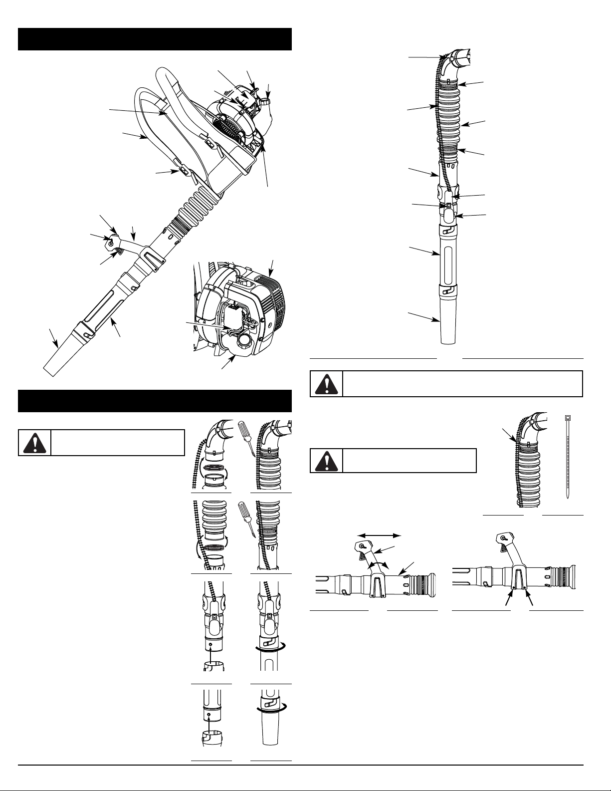
5
Stand
On/Off Switch
Starter Rope
Handle
Muffler
Air Filter Cover
KNOW YOUR UNIT
Primer Bulb
Suspension System
Fuel Tank
Choke Lever
Fuel
Cap
Trigger
Blower Tube
Shoulder Support Buckle
Cruise Control
Nozzle
ASSEMBLY INSTRUCTIONS
ASSEMBLING THE BLOWER TUBE
Installing the Flex Tube
1. Place a hose clamp over the end of the Flex Tube (Fig. 1, A).
2. Slide the end of the Flex Tube with the clamp on it over the
elbow tube (Fig. 1, B).
3. Tighten the screw on the hose clamp to secure the Flex Tube
to the elbow tube (Fig. 1, C).
Installing the Upper Blower Tube
1. Place a hose clamp over the other end of the Flex Tube (Fig.
2, A).
2. Slide the end of the hose with the clamp on it over the top
end of the upper blower tube (Fig. 2, B).
3. Tighten the screw on the hose clamp to secure the Flex Tube
to the upper blower tube (Fig. 2, C).
Installing the Lower Blower Tubes and Nozzle
1. Align the bump slot on the end of the first lower blower tube
with the bump on the bottom end of the upper blower tube
(Fig. 3, A).
2. Insert the bump on the upper blower tube into the bump slot
on the tube extension (Fig. 3, A).
3. Twist the extension tube clockwise around the upper blower
tube until the handle tube bump locks into place (Fig. 3, B).
4. Align the bump slot on the top end of the nozzle with the
bump on the bottom end of the second lower blower tube
(Fig. 4, A).
5. Insert the bump on the second lower blower tube into the
bump slot on the nozzle (Fig. 4, A).
6. Twist the nozzle clockwise around the second lower blower
tube until the nozzle bump locks into place (Fig. 4, B).
Fig. 1
B
A
C
Fig. 2
B
A
C
WARNING:
To avoid serious personal injury
and damage to the unit, shut the unit off before
removing or installing the blower tubes.
A
B
Fig. 3
Shoulder Support
Fig. 5
Adjusting the Throttle Grip
1. Move the throttle grip to a location on the upper blower
tube that is comfortable for you (Fig. 7).
2. Using a Torx T-20 Torx screwdriver, tighten the two screws
at the bottom of the throttle grip (Fig. 8).
Flex Tube
Hose Clamp
Elbow Tube
Upper Blower Tube
Lower Blower Tube
Nozzle
Throttle Cables
Hose Clamp
Cruise Control
Throttle Grip
Fig. 7
A
Fig. 8
Throttle Grip
Fig. 4
B
A
Secure the Throttle Cables
Place a zip tie around the elbow tube and the throttle cables
(Fig. 6) as shown, making sure not to crimp the cables.
The completed blower tube should look like Figure 5.
Fig. 6
Zip Tie
Zip Tie
WARNING:
Do not rotate the handle clockwise
to adjust. This may cause the throttle cables to
disconnect from the throttle grip or the engine.
WARNING:
To avoid serious personal injury, make sure that all four parts of the
blower tube are locked in place or firmly installed.
Throttle Grip
Upper Blower Tube
On/Off Switch
Page 6
Using the Cruise Control
1. Once the engine has started and warmed up, squeeze the trigger
to accelerate the unit as needed (Fig. 11A).
2. For longer periods of operation and to eliminate possible finger fatique, move the cruise control
toward the fast position to incrementally increase or maintain the unit’s engine speed (Fig. 11A).
When the cruise control is pressed, the trigger will recede into the handle.
3. To decrease engine speed, move the cruise control to the idle position and the trigger will return to
idle position (Fig. 11B).
6
OIL AND FUEL MIXING INSTRUCTIONS
Old and/or improperly mixed fuel are the main reasons for the unit
not running properly. Be sure to use fresh, clean unleaded fuel.
Follow the instructions carefully for the proper fuel/oil mixture.
Definition of Blended Fuels
Today's fuels are often a blend of gasoline and oxygenates such
as ethanol, methanol, or MTBE (ether). Alcohol-blended fuel
absorbs water. As little as 1% water in the fuel can make fuel
and oil separate. It forms acids when stored. When using
alcohol-blended fuel, use fresh fuel (less than 60 days old).
Using Blended Fuels
If you choose to use a blended fuel, or its use is unavoidable, follow recommended precautions:
• Always use the fresh fuel mix explained in your operator's manual
• Always agitate the fuel mix before fueling the unit
• Drain the tank and run the engine dry before storing the unit
Using Fuel Additives
The bottle of 2-cycle oil that came with your unit contains a fuel additive which will help inhibit corrosion
and minimize the formation of gum deposits. It is recommended that you use our 2-cycle oil with this
unit. If unavailable, use a good 2-cycle oil designed for air-cooled engines along with a fuel additive,
such as STA-BIL® Gas Stabilizer or an equivalent. Add 0.8 oz. (23 ml.) of fuel additive per gallon of fuel
according to the instructions on the container. NEVER add fuel additives directly to the unit's fuel tank.
Thoroughly mix the proper ratio of 2-cycle engine oil with unleaded gasoline in a separate fuel can. Use a
40:1 fuel/oil ratio. Do not mix them directly in the engine fuel tank. See the table below for specific gas
and oil mixing ratios.
NOTE: One gallon (3.8 liters) of unleaded gasoline mixed with one 3.2 oz. (95 ml.) bottle of 2-cycle oil
makes a 40:1 fuel/oil ratio.
NOTE: Dispose of the old fuel/oil mix in accordance to Federal, State and Local regulations.
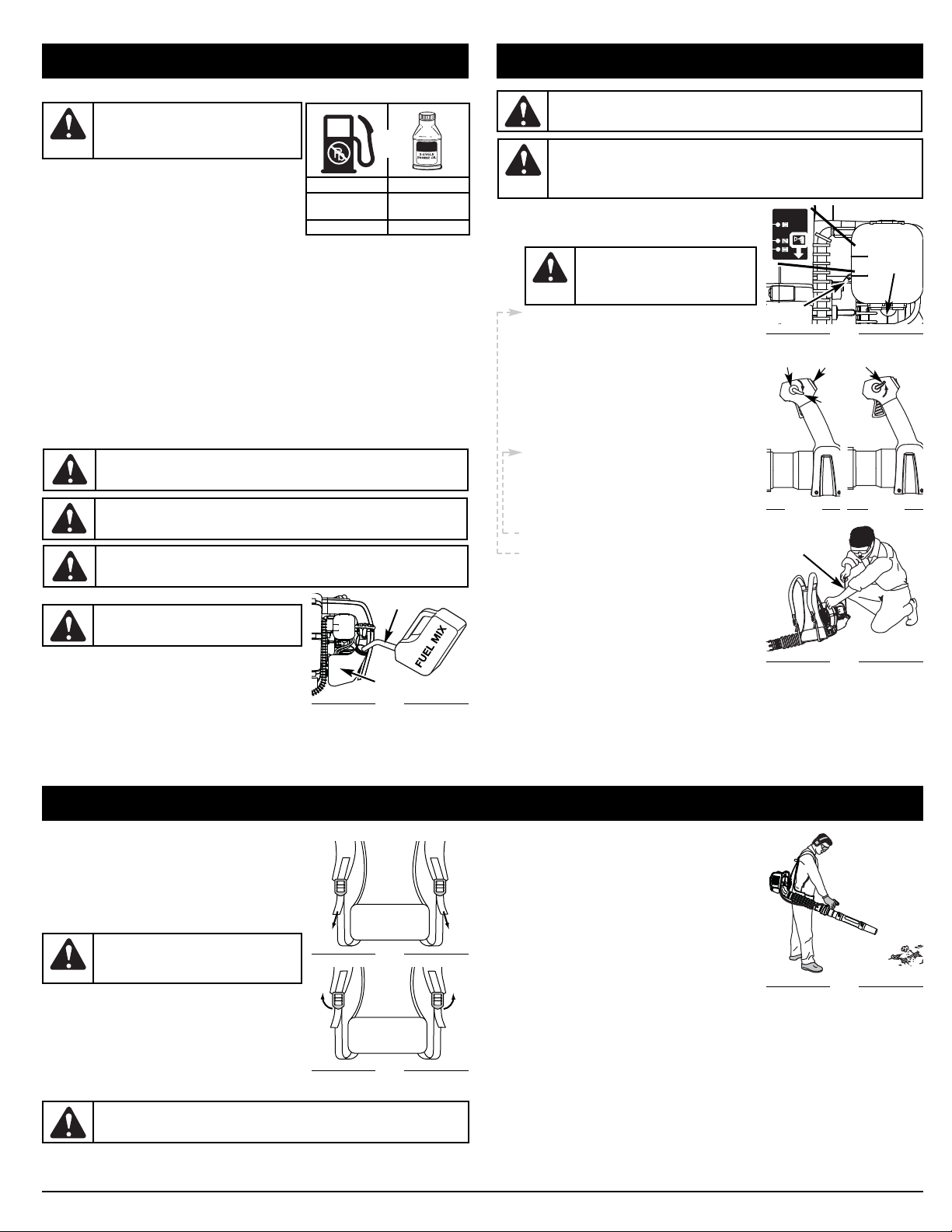
FUELING THE UNIT
1. Remove the fuel cap.
2. Place the gas container’s spout into the fill hole on the fuel
tank (Fig. 9) and fill the tank.
NOTE: Do not overfill the tank.
3. Wipe up any fuel that may have spilled.
4. Reinstall the fuel cap.
5. Move the unit at least 30 ft. (9.1 m) from the fueling source and site before starting the engine.
NOTE: Dispose of the old fuel mixture in accordance to Federal, State and Local regulations.
OIL AND FUEL INFORMATION
Fig. 9
WARNING:
Remove fuel cap slowly to avoid
injury from fuel spray. Never operate the unit
without the fuel cap securely in place.
STARTING INSTRUCTIONS
STARTING/STOPPING INSTRUCTIONS
1. Mix gas with oil. Fill fuel tank with fuel/oil mixture.
See Oil and Fuel Mixing Instructions.
2. Fully press and release the primer bulb 10 times,
slowly. Some amount of fuel should be visible in the
primer bulb and fuel lines (Fig. 10). If you can’t see
fuel in the bulb, press and release the bulb as many
times as it takes until you can see fuel in it.
3. Place the red choke lever in Position 1 (Fig. 10).
4. Press down the cruise control to lock the trigger in
the run position (Fig. 11A).
5. Crouch in the starting position (Fig. 12) and pull the
starter rope 5 times in a smooth and rapid motion.
6. Place the red choke lever in Position 2 (Fig. 10).
7. Pull the starter rope in a smooth and rapid motion
until the engine starts.
8. Allow the engine to warm up for 30 to 60 seconds.
NOTE: Engine may take longer to warm up and reach
maximum operating speed at colder temperatures.
NOTE: Unit is properly warmed up when engine
accelerates without hesitation.
9. Once the engine is warmed up, place the red choke
lever in Position 3 (Fig. 10).
10. Raise the cruise control to return the trigger to the
idle position (Fig. 11B). The unit is ready for use.
IF... the engine hesitates, return the red choke lever to
Position 2 (Fig. 11) and continue warm-up.
IF... the engine does not start, go back to step 2.
IF... the engine fails to start after a few attempts, place
the red choke lever in Position 3 (Fig. 10) and press
down the cruise control. Pull the starter rope briskly 3
to 8 times. The engine should start. If not, repeat.
IF WARM... If the engine is already warm, start the unit
with the red choke lever in Position 2 (Fig. 10). After
the unit starts, move the red choke lever to Position
3 (Fig. 10) and raise the cruise control.
WARNING:
Avoid accidental starting. Make sure you are in the starting position when
pulling the starter rope (Fig. 12). To avoid serious injury, the operator and unit must be
in a stable position while starting.
To avoid serious personal injury, make sure that the blower tube is locked in place or
firmly installed.
WARNING:
Operate this unit only in a well-ventilated outdoor area. Carbon monoxide
exhaust fumes can be lethal in a confined area.
Fig. 10
Primer
Bulb
Choke
Lever
Fig. 12
Starter Rope
OPERATING INSTRUCTIONS
ADJUSTING THE SUSPENSION SYSTEM
1. Place the unit’s shoulder supports over the shoulders while
the unit is behind you.
2. Pull the shoulder support handles to tighten the shoulder
supports (Fig. 13).
Releasing the Suspension System
1. To release the shoulder supports, pull up on bottom tab of
the shoulder support buckles (Fig. 14).
HOLDING THE BLOWER
Before operating the unit, stand in the operating position (Fig. 15).
Check for the following:
• Operator is wearing proper clothing, such as boots, safety
glasses or goggles, ear/hearing protection, gloves, long pants
and long sleeve shirt.
• If the conditions are dusty, the operator is wearing a dust
mask or face mask.
• The unit is in good working condition.
• The tubes are in place and secure.
OPERATING TIPS
• Assure the unit is not directed at anybody or any loose debris before starting the unit.
• Verify that the unit is in good working condition. Make sure the tubes are in place and secure.
• Always hold the unit securely when operating.
WARNING:
To avoid serious personal injury,
wear goggles or safety glasses at all times when
operating this unit. Wear a face mask or dust
mask in dusty locations.
Fuel Can Spout
Fuel Tank
• To reduce the risk of hearing loss associated with sound
level(s), hearing protection is required.
• Operate power equipment only at reasonable hours— not
early in the morning or late at night when people might be
disturbed. Comply with times listed in local ordinances. Usual
recommendations are 9:00 am to 5:00 pm, Monday through
Saturday.
• To reduce noise levels, limit the number of pieces of
equipment used at any one time.
• To reduce noise levels, operate power blowers at the lowest
possible speed to do the job.
• Check your equipment before operation, especially the
muffler, air intakes and air filters.
• Use rakes and brooms to loosen debris before blowing.
• In dusty conditions, slightly dampen surfaces or use a mister
attachment when water is available.
• Conserve water by using power blowers instead of hoses for many lawn and garden applications,
including areas such as screens, patios, grills, porches, and gardens.
• Watch out for children, pets, open windows or freshly washed cars, and blow debris safely away.
• Use the full blower nozzle extension so the air stream can work close to the ground.
• Clean up after using blowers and other equipment. Dispose of debris appropriately.
• Use the cruise control (Fig. 11, A) to keep the trigger depressed while operating to make continuous
operation easier.
APPLICATIONS
1 Use the blower for trees, shrubs, flower beds and hard-to-clean areas.
2. Use the unit around buildings and for other normal cleaning procedures.
3. Use the blower around walls, overhangs, fences and screens.
WARNING:
To prevent serious personal injury or damage to the unit, make sure
blower tubes are in place before you operate the unit.
Fig. 15
CAUTION:
For proper engine operation and
maximum reliability, pay strict attention to the oil
and fuel mixing instructions on the 2-cycle oil
container. Using improperly mixed fuel can
severely damage the engine.
Fig. 13
Fig. 14
Trigger
in Run
Position
Fig. 11A
On/Off
Switch
Fig. 11B
Cruise
Control
Trigger
in Idle
Position
SLOW
FAST
STOPPING INSTRUCTIONS
1. Release your hand from the trigger or raise the cruise control. Allow the engine to cool down by idling.
2. Press the On/Off Switch in the OFF (O) position and hold until the engine comes to a complete stop
(Fig. 11A).
MIXING RATIO - 40:1
UNLEADED GAS* 2 CYCLE OIL
1 GALLON U.S.
(3.8 LITERS)
3.2 FL. OZ.
(95 ml)
1 LITER 25 ml
+
WARNING:
Gasoline is extremely flammable. Ignited vapors may explode. Always
stop the engine and allow it to cool before filling the fuel tank. Do not smoke while filling
the tank. Keep sparks and open flames at a distance from the area.
WARNING:
Add fuel in a clean, well ventilated outdoor area. Wipe up any spilled fuel
immediately. Avoid creating a source of ignition for spilt fuel. Do not start the engine
until fuel vapors dissipate.
*
WARNING: DO NOT USE E85 FUEL IN THIS UNIT. It has been proven that fuel
containing greater than 15% ethanol will likely damage this engine and void the warranty.
WARNING:
DO NOT USE E85 FUEL
IN THIS UNIT. It has been proven that
fuel containing greater than 15% ethanol
will likely damage this engine and void
the warranty.
3
2
1
Page 7

7
MAINTENANCE AND REPAIR INSTRUCTIONS
AIR FILTER MAINTENANCE
Cleaning the Air Filter
Clean and re-oil the air filter every 25 hours of operation. It is an important item to maintain. Failure to maintain
your air filter properly can result in poor performance or can cause permanent damage to your engine.
1. Open the air filter cover. Push the locking tab on the top of the cover inward, then pull the air filter
cover out and down. (Fig. 16).
2. Remove the air filter (Fig. 17).
3. Wash the filter in detergent and water (Fig. 18). Rinse the filter thoroughly and allow it to dry.
4. Apply enough clean SAE 30 motor oil to lightly coat the filter (Fig. 19).
5. Squeeze the filter to spread and remove excess oil (Fig. 20).
6. Replace the filter (Fig. 17).
NOTE: If the unit is operated without the air filter, you will VOID the warranty.
7. Reinstall the air filter cover. Position the slots on the bottom of the air filter cover onto the tabs at
the bottom of the back plate (Figs. 17).
8. Swing the cover up until the tab on the air filter backplate snaps into place in the slot on the air filter
cover (Fig. 21).
CARBURETOR ADJUSTMENT
The idle speed of the engine is adjustable. An idle adjustment
screw is between the air filter cover and the engine starter
housing (Fig. 22).
NOTE: Careless adjustments can seriously damage your unit. An
authorized service dealer should make carburetor
adjustments.
Check Fuel
Old and/or improperly mixed fuel is usually the reason for improper
unit performance. Drain and refill the tank with fresh, properly-mixed
fuel prior to making any adjustments. Refer to Oil and Fuel Information.
Clean Air Filter
The condition of the air filter is important to the operation of the unit.
A dirty air filter will restrict air flow. This is often mistaken for an out of adjustment carburetor. Check the
condition of the air filter before adjusting the idle speed screw. Refer to Air Filter Maintenance.
FREQUENCY MAINTENANCE REQUIRED SEE
Before using Fill fuel tank with fresh fuel* p 6
Every 25 hrs
Clean and re-oil air filter
Check spark plug condition and gap
p 7
p 7
Every 125 hrs Clean spark arrestor p 7
MAINTENANCE SCHEDULE
Perform these required maintenance procedures at the frequency stated in the table. These procedures
should also be a part of any seasonal tune-up.
NOTE: Some maintenance procedures may require special tools or skills. If you are unsure about these
procedures take your unit to a Cub Cadet or other qualified service dealer.
NOTE: Maintenance, replacement, or repair of the emission control devices and system may be
performed by a Cub Cadet or other qualified service dealer.
In order to assure peak performance of your engine, inspection of the engine exhaust port may be
necessary after 125 hours of operation. If you notice lost RPM, poor performance or general lack of
acceleration, this service may be required. If you feel your engine is in need of this inspection, refer service
to a Cub Cadet or other qualified service dealer for repair. DO NOT attempt to perform this process
yourself as engine damage may result from contaminants involved in the cleaning process for the port.
WARNING:
To prevent serious injury, never perform maintenance or repairs with unit
running. Always service and repair a cool unit. Disconnect the spark plug wire to ensure
that the unit cannot start. See Replacing the Spark Plug.
Fig. 17
Air Filter
Back
Plate
Tab s
Locking Tab
Fig. 16
Locking Tab
Air Filter
Cover
Fig. 18
Fig. 19
Fig. 21
Locking Tab
Air Filter
Cover
Fig. 20
Fig. 22
Idle Adjustment
Screw
Adjust Idle Speed Screw
If, after checking the fuel and cleaning the air filter, the engine still will not idle, adjust the idle speed
screw as follows:
1. Start the engine and let it run at a high idle for a minute to warm up. Refer to Starting/Stopping
Instructions.
2. Release the throttle trigger and let the engine idle. If the engine stops, insert a small phillips in
between the Air Filter Cover and the Engine Cover (Fig. 22). Turn the idle speed screw in, clockwise,
1/8 of a turn at a time (as needed) until the engine idles smoothly.
Checking the fuel mixture, cleaning the air filter, and adjusting the idle speed should solve most engine
problems. If not and all of the following are true:
• the engine will not idle
• the engine hesitates or stalls on acceleration
• there is a loss of engine power
Have the carburetor adjusted by an authorized service dealer.
REPLACING THE SPARK PLUG
Use a Champion #RDZ4H or a replacement part number 75305784 spark plug. The correct air gap is 0.025 in. (0.635 mm).
Remove the plug after every 25 hours of operation and check its
condition.
1. Stop the engine and allow it to cool.
2. Grasp the plug wire firmly and pull the cap from the spark plug.
3. Clean dirt from around the spark plug. Remove the spark
plug from the cylinder head by turning a 5/8 in. socket
counterclockwise.
4. Replace cracked, fouled or dirty spark plug. Set the air gap at
0.025 in. (0.635 mm) using a feeler gauge (Fig. 23).
5. Install a correctly-gapped spark plug in the cylinder head.
Turn the 5/8 in. socket clockwise until snug.
If using a torque wrench torque to:
110-120 in.•lb. (12.3-13.5 N•m)
Do not over tighten.
SPARK ARRESTOR MAINTENANCE
Inspect the spark arrestor after every 125 hours of operation.
1. Stop the engine and allow it to cool. Remove the four (4)
screws on the back of the engine cover with a flat-head
screwdriver or T-25 Torx bit (Fig. 24).
2. With a
Phillips
screwdriver, remove the screws attaching the
spark arrestor cover to the muffler (Fig. 25).
3. Remove the spark arrestor cover.
4. Remove the spark arrestor screen from the spark arrestor
cover (Fig. 25).
5. Clean the spark arrestor screen with a wire brush or replace it.
6. Reinstall the spark arrestor screen, spark arrestor cover and screws.
CLEANING
Use a small brush to clean off the outside of the unit. Do not use strong detergents. Household cleaners
that contain aromatic oils such as pine and lemon, and solvents such as kerosene, can damage plastic
housing or handle. Wipe off any moisture with a soft cloth.
STORAGE
• Never store the unit with fuel in the tank where fumes may reach an open flame or spark.
• Allow the engine to cool before storing.
• Lock up the unit to prevent unauthorized use or damage.
• Store the unit in a dry, well-ventilated area.
• Store the unit out of the reach of children.
LONG TERM STORAGE
If you plan on storing the unit for an extended time, use the following storage procedure:
1. Drain all fuel from the fuel tank into a container with the same 2-cycle fuel mixture. Do not use fuel
that has been stored for more than 60 days. Dispose of the old fuel/oil mix in accordance to Federal,
State and Local regulations.
2. Start the engine and allow it to run until it stalls. This ensures that all fuel has been drained from the
carburetor.
3. Allow the engine to cool. Remove the spark plug and put 1 oz. (30 ml) of any high quality motor oil
or 2-cycle oil into the cylinder. Pull the starter rope slowly to distribute the oil. Reinstall the spark
plug.
NOTE: Remove the spark plug and drain all of the oil from the cylinder before attempting to start the
trimmer after storage.
4. Thoroughly clean the unit and inspect it for any loose or damaged parts. Repair or replace damaged
parts and tighten loose screws, nuts or bolts. The unit is ready for storage.
TRANSPORTING
• Allow the engine to cool before transporting
• Drain fuel from unit
• Tighten fuel cap before transporting
• Secure the unit while transporting
Fig. 24
T- 25
Screws
T- 25
Screws
Fig. 23
0.025 in.
(0.635 mm)
WARNING:
Do not sand blast, scrape or
clean electrodes. Grit in the engine could
damage the cylinder.
*
DO NOT use E85 fuel in this unit. It has been proven that fuel containing greater than
15% ethanol will likely damage this engine and void the warranty.
Fig. 25
Muffler
Spark Arrestor
Screen
Spark Arrestor
Cover
Philips Head
Screws
WARNING:
To avoid serious personal injury,
always turn your unit off and allow it to cool
before you clean or service it.
Page 8

8
TROUBLESHOOTING
If further assistance is required, contact your authorized service dealer.
CAUSE ACTION
Air filter is plugged Replace or clean the air filter
Old or improperly mixed fuel Drain fuel tank and add fresh fuel mixture
Improper carburetor adjustment Adjust according to the Carburetor Adjustments
section or take to an authorized service dealer
for an adjustment
CAUSE ACTION
Empty fuel tank Fill fuel tank with properly mixed fuel
Primer bulb wasn't pressed enough Press primer bulb fully and slowly 10 times
Old or improperly mixed fuel Drain fuel tank and add fresh fuel mixture
Fouled spark plug Replace or clean the spark plug
Plugged spark arrestor Clean or replace spark arrestor
CAUSE ACTION
Old or improperly mixed fuel Drain fuel tank and add fresh fuel mixture
Improper carburetor adjustment Adjust according to the Carburetor Adjustments
section or take to an authorized service dealer
for an adjustment
Dirty air filter Clean or replace the air filter
Plugged spark arrestor Clean or replace spark arrestor
ENGINE WILL NOT START
ENGINE WILL NOT IDLE
ENGINE WILL NOT ACCELERATE
ENGINE LACKS POWER OR STALLS
SPECIFICATIONS
* All specifications are based on the latest product information available at the time of printing. We
reserve the right to make changes at any time without notice.
ENGINE*
Engine Type. . . . . . . . . . . . . . . . . . . . . . . . . . . . . . . . . . . . . . . . . . . . . . . . . . . . . . . . . Air-Cooled, 2-Cycle
Displacement . . . . . . . . . . . . . . . . . . . . . . . . . . . . . . . . . . . . . . . . . . . . . . . . . . . . . . . . . . . . . . . . . . . . 27 cc
Idle Speed RPM. . . . . . . . . . . . . . . . . . . . . . . . . . . . . . . . . . . . . . . . . . . . . . . . . . . . . . . . 3,800–4,200 rpm
Operating RPM . . . . . . . . . . . . . . . . . . . . . . . . . . . . . . . . . . . . . . . . . . . . . . . . . . . . . . . . 7,800–8,200 rpm
MPH. . . . . . . . . . . . . . . . . . . . . . . . . . . . . . . . . . . . . . . . . . . . . . . . . . . . . . . . . . . . . . . . . . . . . . . . . 150–175
CFM. . . . . . . . . . . . . . . . . . . . . . . . . . . . . . . . . . . . . . . . . . . . . . . . . . . . . . . . . . . . . . . . . . . . . . . . . 450–500
Ignition Type. . . . . . . . . . . . . . . . . . . . . . . . . . . . . . . . . . . . . . . . . . . . . . . . . . . . . . . . . . . . . . . . . Electronic
Ignition Switch . . . . . . . . . . . . . . . . . . . . . . . . . . . . . . . . . . . . . . . . . . . . . . . . . . . . . . . . . . . Rocker Switch
Spark Plug Gap . . . . . . . . . . . . . . . . . . . . . . . . . . . . . . . . . . . . . . . . . . . . . . . . . . . . . 0.025 in. (0.635 mm)
Lubrication . . . . . . . . . . . . . . . . . . . . . . . . . . . . . . . . . . . . . . . . . . . . . . . . . . . . . . . . . . . . . Fuel/Oil Mixture
Fuel/Oil Ratio. . . . . . . . . . . . . . . . . . . . . . . . . . . . . . . . . . . . . . . . . . . . . . . . . . . . . . . . . . . . . . . . . . . . . 40:1
Carburetor . . . . . . . . . . . . . . . . . . . . . . . . . . . . . . . . . . . . . . . . . . . . . . . . . . . . . . . Diaphragm, All-Position
Starter . . . . . . . . . . . . . . . . . . . . . . . . . . . . . . . . . . . . . . . . . . . . . . . Spring Assist Starting™ Auto Rewind
Muffler . . . . . . . . . . . . . . . . . . . . . . . . . . . . . . . . . . . . . . . . . . . . . . . . . . . . . . . . . . . . . . Baffled with Guard
Throttle . . . . . . . . . . . . . . . . . . . . . . . . . . . . . . . . . . . . . . . . . . . . . . . . . . . . . . . . . . . Manual Spring Return
Fuel Tank Capacity . . . . . . . . . . . . . . . . . . . . . . . . . . . . . . . . . . . . . . . . . . . . . . . . . . . . . . . . 20 oz. (591 ml)
Page 9

Manuel de L'utilisateur
Souffleur à dos à 2-temps
BP226
P/N 769-04595 P00 (01/09)
Copiez le numéro de série ici :
Copiez le numéro de modèle / pièce mère ici :
Toutes les informations, illustrations et spécifications contenues dans
ce manuel tiennent compte des dernières informations techniques
disponibles au moment de mettre sous presse. Nous nous réservons
le droit d'y apporter des modifications à tout moment, sans préavis.
Copyright© 2009 MTD SOUTHWEST INC., Tous droits réservés.
Obtenez la liste des concessionnaires agréés appelez le 1-877-282-8684
aux États-Unis ou le 1-800-668-1238 au Canada. Pour de plus amples
informations à propos de votre appareil, visitez www.cubcadet.com
ou www.cubcadet.ca.
NE RETOURNEZ PAS L'APPAREIL AU DÉTAILLANT CHEZ QUI
VOUS L'AVEZ ACHETÉ. TOUT SERVICE SOUS GARANTIE
NÉCESSITE UNE PREUVE D'ACHAT.
CE PRODUIT EST COUVERT PAR UN OU PLUSIEURS BREVETS
AMÉRICAINS, ET D’AUTRES SONT EN INSTANCE.
Tout entretien effectué sur cet appareil pendant et après la période
de garantie doit être fait par un concessionnaire agréé uniquement.
Avant d'assembler votre nouvel équipement, repérez la plaque
signalétique de l'appareil et copiez ses informations dans l'espace cidessous. Ces informations sont essentielles si vous désirez obtenir de
l'aide auprès de notre service technique ou d'un distributeur agréé. Un
exemple de plaque signalétique est présenté ci-dessous.
CONSERVER CES INSTRUCTIONS
TABLE DES MATIÈRES
Service technique . . . . . . . . . . . . . . . . . . . . . . . . . . . . . . . . . . . . .F1
Consignes de sécurité . . . . . . . . . . . . . . . . . . . . . . . . . . . . . . . . .F2
Familiarisez-vous avec l’appareil . . . . . . . . . . . . . . . . . . . . . . . . .F5
Instructions de montage . . . . . . . . . . . . . . . . . . . . . . . . . . . . . . .F5
Informations sur l’huile et le carburant . . . . . . . . . . . . . . . . . . . .F6
Instructions de démarrage et d’arrêt . . . . . . . . . . . . . . . . . . . . . .F6
Mode d’emploi . . . . . . . . . . . . . . . . . . . . . . . . . . . . . . . . . . . . . . .F6
Entretien et réparations . . . . . . . . . . . . . . . . . . . . . . . . . . . . . . . .F7
Nottoyage et entreposage . . . . . . . . . . . . . . . . . . . . . . . . . . . . . .F7
Tableau de dépannage . . . . . . . . . . . . . . . . . . . . . . . . . . . . . . . . .F8
Caractéristiques . . . . . . . . . . . . . . . . . . . . . . . . . . . . . . . . . . . . . .F8
Garantie . . . . . . . . . . . . . . . . . . . . . . . . . . . . . . . . . . . . . . . . . . .E12
Dans un effort de réduire l’impact sur les forets et
réduire les émissions de gaz carbonique ainsi
que les émissions de gaz à effet de serre, MTD
utilise moins de papier en réduisant la taille du
texte de ce manuel.
NE RETOURNEZ
PAS CE PRODUIT
Pour une assistance, veuillez appeler le 1-877-282-8684
(E.U.) ou le 1-800-668-1238 (Canada)
ou visitez : www.cubcadet.com / www.cubcadet.ca
MODEL :
S/N :
ITEM :
Page 10

F2
• IMPORTANTES CONSIGNES DE SÉCURITÉ •
• Toujours arrêter le moteur et le laisser refroidir avant faire l’appoint de
carburant. Ne jamais retirer le bouchon du réservoir de carburant ou
faire l’appoint pendant que le moteur est chaud. Ne jamais utiliser
l’outil sans que le bouchon du réservoir soit bien en place. Desserrer
le bouchon lentement afin de relâcher la pression du réservoir.
• Ajoutez le carburant dans un endroit bien aéré et propre, en plein
air, à l’abri des sources d’étincelles ou flammes vives. Ne retirer
(lentement) le bouchon du réservoir d’essence qu’après avoir
arrêté le moteur. Ne pas fumer pendant l’approvisionnement de
carburant. Essuyer immédiatement le carburant répandu sur l’outil.
• Éviter de créer une source d’allumage pour le carburant répandu.
Ne pas lancer le moteur avant que toutes les vapeurs se soient
dissipées, afin d’éviter de créer une source d’allumage pour le
carburant répandu.
• Éloigner l’outil d’au moins 9 m (30 pi) du point d’approvisionnement
en carburant avant de démarrer le moteur. Ne pas fumer et éloigner
toute source d’étincelles ou de flammes vives du point
d’approvisionnement ou d’utilisation de l’outil.
PENDANT L’UTILISATION
• Ne jamais démarrer ou utiliser l’outil dans un local clos.
L’inhalation des vapeurs d’échappement peut être mortelle.
N’utiliser l’outil qu’à l’extérieur, dans un endroit bien aéré.
• Pour réduire les risques de blessures par des objets projetés, porter
des lunettes de sécurité conformes à la norme ANSI Z87.1–1989.
• Ne jamais utiliser l’outil s’il n’est pas équipé des accessoires
nécessaires.
• Pour réduire les risques de perte de l’ouïe causée par le niveau de
bruit, toujours porter une protection auditive lors de l’utilisation.
• Portez des pantalons épais et longs, des bottes, des gants et une
chemise à manches longues. Ne marchez pas pieds nus et évitez
LISEZ TOUTES LES INSTRUCTIONS AVANT L'UTILISATION
• Veuillez lire les instructions avec soin. Familiarisez-vous avec les
commandes et l'utilisation correcte de cet appareil.
• Veuillez lire le manuel de l'utilisateur attentivement. Familiarisez-vous avec
les commandes et l'utilisation correcte de l’appareil. Sachez comment
arrêter l’appareil et désactiver les commandes rapidement.
• N'utilisez pas l'appareil si vous êtes fatigué, malade ou sous
l'effet de l'alcool, de drogues ou de médicaments.
• Ne laissez pas les enfants faire fonctionner l’appareil. Ne laissez jamais
des adultes qui ne se sont pas familiarisés avec les instructions utiliser
l’appareil. Ne laissez jamais des adultes n'ayant jamais reçu les
instructions nécessaires faire fonctionner l’appareil.
• Tous les tubes du soffleur doivent être correctement installés
avant d'utiliser cet appareil.
AVERTISSEMENTS DE SÉCURITÉ SPÉCIAUX POUR TÊTES
D’ENTRAÎNEMENT À ESSENCE
• Ne conserver le carburant que dans des récipients spécialement
conçus et homologués pour le stockage de ce type de produit.
Lisez le(s) manuel(s) de l'utilisateur et suivez tous les avertissements et consignes de sécurité. Vous pourriez à défaut entraîner des
blessures graves pour vous ou d'autres personnes.
SI VOUS AVEZ DES QUESTIONS, APPELEZ LE
1-877-282-8684
AUX ÉTATS-UNIS, OU LE 1-800-668-1238 AU CANADA
Les symboles de sécurité attirent votre attention sur des dangers
potentiels. Ces symboles et leurs détails explicatifs méritent que
vous les lisiez et compreniez bien. Les avertissements de
sécurité ne peuvent éviter les dangers de par eux-mêmes. Les
consignes ou mises en garde qu'ils donnent ne remplacent pas
des mesures préventives appropriées contre les accidents.
REMARQUE: donne des informations ou des instructions vitales
pour le fonctionnement ou l'entretien de l'équipement.
ALERTE DE SÉCURITÉ :
Indique un danger, un
avertissement ou une mise en garde. Soyez vigilant afin
d'éviter toute blessure grave. Ce symbole peut être
combiné à d'autres symboles ou pictogrammes.
DANGER :
l e non-respect d’un avertissement peut
causer dommages matériels ou blessures graves pour
tous. Respectez les consignes de sécurité afin de réduire
les risques d'incendie, d'électrocution et de blessures.
AVERTISSEMENT :
le non-respect d’un avertissement
peut causer dommages matériels ou blessures graves pour
tous. Respectez les consignes de sécurité afin de réduire les
risques d'incendie, d'électrocution et de blessures.
MISE EN GARDE :
le non-respect d’un avertissement
peut causer dommages matériels ou blessures graves pour
tous. Respectez toujours les consignes de sécurité afin de
réduire les risques d'incendie, d'électrocution et de
blessures.
CONSIGNES DE SÉCURITÉ
SYMBOLE SIGNIFICATION
AVERTISSEMENT :
Suivez soigneusement les
consignes de sécurité lorsque vous utilisez cet appareil.
Dans l'intérêt de votre sécurité et de celle des personnes
à proximité, prenez soin de lire ces instructions avant de
faire fonctionner la machine. Veuillez garder les
instructions en lieu sûr pour usage ultérieur.
AVERTISSEMENT :
L'essence est extrêmement
inflammable et ses vapeurs peuvent exploser si on y
met le feu. Veuillez prendre les précautions suivantes.
PARE-ÉTINCELLES
REMARQUE : à l'intention des utilisateurs opérant dans les
terres forestières des États-Unis et dans les états de Californie,
du Maine, de l'Orégon et de Washington. Toutes les terres
forestières des États-Unis et de l'état de Californie (Codes sur les
ressources publiques 4442 et 4443), de l'Orégon et de Washington
exigent de par la loi que certains moteurs à combustion interne
utilisés dans des zones couvertes de taillis ou d'herbe soient
équipés d'un pare-étincelles en parfait état de fonctionnement, ou
qu'ils soient conçus, équipés et entretenus pour la prévention des
incendies. Renseignez-vous auprès des autorités de votre province
ou de votre municipalité concernant la réglementation en vigueur.
Vous pourriez être passible d'une amende ou être tenu responsable
si vous ne respectez pas cette réglementation. Cet appareil est
équipé d'un pare-étincelles en usine. Si silencieux, réf. 753-05945,
doit être remplacé, communiquez avec le service technique.
AVERTISSEMENT DE LA PROPOSITION 65 DE CALIFORNIE
AVERTISSEMENT
LES GAZ D'ÉCHAPPEMENT DU MOTEUR DE CET
APPAREIL CONTIENNENT DES PRODUITS CHIMIQUES
CONSIDÉRÉS PAR L'ÉTAT DE CALIFORNIE COMME
POUVANT CAUSER LE CANCER, DES MALFORMATIONS
CONGÉNITALES OU D'AUTRES EFFETS NOCIFS SUR
L'APPAREIL DE REPRODUCTION.
Page 11

F3
CONSIGNES DE SÉCURITÉ
les vêtements lâches, bijoux, pantalons courts et sandales. Relevez
les cheveux au-dessus des épaules.
• Ne pas porter de gants en caoutchouc ou isolés pour éviter les
décharges d’électricité statique lors de l’utilisation.
• N’utiliser l’outil qu’en plein jour ou sous bon éclairage artificiel.
• Garder l’extérieur de l’outil exempt d’huile et de carburant.
• Éviter tout démarrage accidentel. Toujours se tenir en position
de démarrage avant de tirer la corde de démarrage. L’opérateur
et l’outil doivent tous deux être en position d’équilibre lors du
démarrage. Voir les instructions de Démarrage et arrêt.
• L’outil doit toujours être posé sur une surface propre et ferme.
Les matériaux tels que le gravier, le sable, la poussière, l’herbe,
etc. peuvent être aspirés par l’admission d’air et projetés par la
sortie de l’outil, ce qui peut endommager l’outil, causer des
dégâts matériels et des blessures graves à l’utilisateur ou aux
personnes se trouvant à proximité.
• Toujours utiliser un outil adéquat pour l’application. Ne pas
utiliser cet outil pour un usage pour lequel il n’est pas conçu.
• Ne pas forcer l’outil. Il fonctionnera plus efficacement et sera
moins dangereux si sa capacité nominale n’est pas dépassée.
• Ne pas essayer de travailler hors de portée ou en se tenant sur
une surface instable, telle qu’une échelle, un arbre, un toit, une
pente abrupte, un toit, etc. Toujours se tenir bien campé, en
position d’équilibre.
• Toujours tenir l’outil fermement pendant l’utilisation.
• Garder les mains, le visage et les pieds à l’écart des pièces en
mouvement. Ne pas essayer de toucher ou d’arrêter l’hélice en
rotation. Ne pas utiliser l’outil si les dispositifs de protection ne
son pas en place.
• Ne jamais introduire quoi que ce soit dans les ouvertures. Garder
les ouvertures dégagées, exemptes de poussières et de débris
ou autres risquant de réduire la circulation d’air.
• Ne toucher ni le moteur, ni le silencieux. Ces pièces deviennent
très chaudes pendant le fonctionnement. Elles restent brûlantes
pendant quelques temps après l’arrêt.
• Ne pas faire fonctionner le moteur à un régime plus qu’il n’est
nécessaire pour s’acquitter de la tâche. Ne pas faire tourner le
moteur à haut régime à vide.
• Toujours arrêter le moteur si le travail est interrompu ou avant de
se déplacer d’un endroit à un autre.
• Arrêter le moteur et débrancher avant toute opération d’entretien
ou réparation et avant d’installer ou retirer les tubes de
souffleuse. Le moteur et les pales de l’hélice doivent être
parvenus à l’arrêt complet pour éviter tout danger de blessure
par les pièces en rotation.
• Si l’appareil heurte ou se prend dans un objet, arrêtez le moteur
immédiatement et vérifiez que l’appareil n’a pas été
endommagé. Ne pas utiliser avant d’avoir réparé les dommages.
Ne pas utiliser l’appareil avec des pièces ayant du jeu ou qui
sont endommagées.
• N'utilisez que des pièces de équipement original rechange du
fabricant pour cet appareil. Elles sont disponibles auprès de votre
concessionnaire agréé. L'utilisation de pièces ou accessoires
autres que ceux de éqiupement original peut causer des
blessures graves, endommager l’appareil et annuler sa garantie.
• Ne jamais utiliser cet outil pour répandre des produits chimiques,
engrais ou matériaux pouvant contenir des substances toxiques.
• Afin de réduire les risques d’incendie, remplacer tout silencieux
ou pare-étincelles défectueux et garder le moteur et le silencieux
exempts d’herbe, de feuilles et d’accumulation excessive de
graisse ou de calamine.
• Éteignez le moteur et débranchez la bougie pour effectuer son
entretien ou sa réparation.
• Ne jamais diriger le tube de la souffleuse vers des personnes,
animaux domestiques ou fenêtres. Toujours souffler les débris en
direction opposée des personnes, animaux domestiques et
fenêtres. Redoubler de prudence lors du travail à proximité
d’objets massifs tels que des arbres, véhicules, murs, etc.
AUTRES AVERTISSEMENTS DE SÉCURITÉ
• Toujours débrancher la bougie avant de travailler sur les pièces
mobiles.
• N’entreposez jamais l’appareil avec de l’essence dans le
réservoir à l’intérieur d’un bâtiment où les vapeurs peuvent
entrer en contact avec toute source de flammes (lampes témoin,
etc.) ou d’étincelles (interrupteurs, moteurs électriques, etc.).
• Laisser le moteur refroidir avant de remiser ou transporter l’outil.
Bien arrimer l’outil pour le transport.
• Remiser l’outil dans un endroit sec pouvant être verrouillé ou en
hauteur afin d’empêcher des dommages ou un usage non
autorisé. Garder l’outils hors de portée des enfants.
• Ne jamais immerger l’outil et ne jamais l’arroser avec de l’eau ou
tout autre liquide. Garder les poignées sèches, propres et
exemptes de débris. Nettoyer après chaque usage. Voir les
sections Nettoyage et Remisage.
• Conserver ces instructions. Les consulter fréquemment et les
utiliser pour instruire d’autres utilisateurs. Si l’outil est prêté, il
doit être accompagné de ces instructions.
REMARQUE SPÉCIALE: L’exposition à des vibrations due à un
usage prolongé d’outils à essence peut entraîner une lésion des
vaisseaux sanguins ou des nerfs au niveau des doigts, mains et
articulations des personnes prédisposées aux troubles de la
circulation et aux tuméfactions anormales. L’utilisation prolongée
en eau froide a été reliée aux lésions des vaisseaux sanguins chez
des personnes normalement en santé. En cas de symptômes tel
qu’engourdissement, douleur, perte de force, changement de
couleur ou de texture de la peau, perte de sensation dans les
doigts, les mains ou les articulations, cessez l’utilisation de
l’appareil et consultez un médecin. Un système anti-vibration ne
garantit pas que ce genre de problème puisse être évité. Les
individus utilisant des outils mécaniques de manière régulière
doivent surveiller attentivement leur état physique et celui de
l’appareil.
CONSERVER CES INSTRUCTIONS
Page 12

F4
• SYMBOLES DE SÉCURITÉ ET INTERNATIONAUX •
Ce manuel de l'utilisateur décrit les symboles et pictogrammes de sécurité et internationaux pouvant apparaître sur ce produit. Consultez le
manuel de l'utilisateur pour les informations concernant la sécurité, le montage, le fonctionnement, l'entretien et les réparations.
CONSIGNES DE SÉCURITÉ
• LISEZ LE MANUEL DE L'UTILISATEUR
AVERTISSEMENT : Lisez le manuel de
l'utilisateur et suivez tous les avertissements et
consignes de sécurité. Vous pourriez à défaut
entraîner des blessures graves pour vous ou d'autres
personnes.
SYMBOLE SIGNIFICATION
• SYMBOLE ALERTE DE SÉCURITÉ
Indique un danger, un avertissement ou une mise en
garde. Ce symbole peut être combiné à d'autres
symboles ou pictogrammes.
SYMBOLE SIGNIFICATION
• COMMANDE MARCHE/ARRÊT
ARRÊT
• COMMANDE MARCHE/ARRÊT
ALLUMAGE / DÉMARRAGE / MARCHE
• NIVEAU D'HUILE
Voir le manuel de l'utilisateur pour le type d'huile
approprié.
• CARBURANT SANS PLOMB
Utilisez toujours du carburant sans plomb frais et
propre.
• ÉLOIGNEZ LES SPECTATEURS
AVERTISSEMENT : Éloignez tout spectateur,
les enfants et les animaux domestiques en
particulier, d'au moins 15 m (50 pieds) de la zone de
coupe.
•
LES OBJETS PROJETÉS
PEUVENT CAUSER DES
BLESSURES GRAVES
AVERTISSEMENT : Tenez-vous à l'écart de la
sortie de souffleuse. Ne dirigez jamais la souffleuse vers
vous ou vers les autres. La souffleuse peut projeter des
objets. Ne faites pas fonctionner l'appareil sans les
accessoires et protections nécessaires.
• CONTRÔLE DE L'ÉTRANGLEUR
1. • Position d’ÉTRANGLEMENT MAXIMUM
2. • Position d’ÉTRANGLEMENT PARTIEL
3. • Position MARCHE
• SURFACE CHAUDE
AVERTISSEMENT : Ne pas toucher aux
surfaces chaudes. Vous pourriez vous brûler. Ces
pièces deviennent très chaudes à l'utilisation. Elles
restes chaudes brièvement après l'arrêt.
• PORTEZ DES PROTECTIONS (TÊTE, YEUX ET
OREILLES)
AVERTISSEMENT : Les objets projetés et les
bruits forts peuvent endommager la vue et l’ouïe.
Portez une visière de norme ANSI Z87.1–1989 et des
protège-oreilles pendant l'utilisation. la chute d’objets
peut causer des blessures graves à la tête. Protégezvous la tête pendant l'utilisation de l'appareil.
Page 13

F5
SAVOIR VOTRE UNITÉ
Pied
Commande
Marche/Arrêt
Poignée du
cordon du
démarreur
Silencieux
Couvercle du filtre
à air/silencieux
Poire
d'amorçage
Système de support
Réservoir
Levier
d’étranglement
Bouchon
du
carburant
Gâchette
Tube de soufflage
Boucle de la support d’épaule
Régulateur de
vitesse
Poignée de la
manette des gaz
Buse
ASSEMBLAGE DU TUBE DU SOUFFLEUR
Installer le Flex Tube
1. Placer un collier de serrage à l’extrémité du tube flexible (Fig. 1, A).
2. Glisser l’extrémité du tube flexible avec le collier de serrage en
place sur la sortie de la buse du logement de l’hélice (Fig. 1, B).
3. Aligner la bosse sur le tube flexible avec la bosse de la buse
du moteur (Fig. 1, C).
4. Serrer la visse du collier de serrage pour fixer le tube flexible
à buse de sortie de l’hélice (Fig. 1, C).
Installer le tube de soufflage supérieur
1. Placer un collier de serrage à l’autre extrémité du tube flexible
(Fig. 2, A).
2. Glisser cette extrémité du tube avec le collier de serrage en
place sur l’extrémité supérieure du tube de soufflage
supérieur (Fig. 2, B).
3. Serrer la visse du collier de serrage pour fixer le tube flexible
au tube de soufflage supérieur (Fig. 2, C).
Installer les tubes de soufflage inférieurs et la buse
1. Aligner l’encoche sur l’extrémité du premier tube de soufflage
inférieur avec la bosse sur l’extrémité inférieure du tube de
soufflage supérieur (Fig. 3, A).
2. Insérer la bosse sur le tube de soufflage supérieur dans
l’encoche sur le tube d’extension (Fig. 3, A).
3. Pivoter le tube d’extension dans le sens des aiguilles d’une
montre autour du tube de soufflage supérieur jusqu’à ce que
la bosse du tube se verrouille en place (Fig. 3, B).
4. Aligner l’encoche sur la partie supérieure de la buse avec la
bosse sur l’extrémité inférieure du second tube de soufflage
inférieur (Fig. 4, A).
5. Insérer la bosse sur le tube de soufflage supérieur dans
l’encoche de la buse (Fig. 4, A).
6. Pivoter la buse dans le sens des aiguilles d’une montre autour
du tube de soufflage inférieur jusqu’à ce que la bosse de la
buse se verrouille en place (Fig. 4, B).
Fig. 1
B
A
C
Fig. 2
B
A
C
AVERTISSEMENT :
Afin d’éviter de graves
blessures et éviter d’endommager l’appareil,
coupez le moteur avant de retirer ou d’installer
les tubes du souffleur.
A
B
Fig. 3
Supports d’épaules
Fig. 5
Ajuster la prise de la manette des gaz
1. Bougez la prise de la manette des gaz vers un endroit sur le
tube de soufflage supérieur qui vous est confortable (Fig. 7).
2. A l’aide d’un tournevis Torx T-20, serrez les deux vis au bas
de la prise de la manette des gaz (Fig. 8).
Tube flexible
Collier de serrage
Tube en coude
Tube de soufflage
supérieur
Tube de soufflage
inférieur
Buse
Câbles des gaz
Collier de serrage
Régulateur de vitesse
Poignée de la manette
des gaz
AVERTISSEMENT :
Afin d’éviter de graves blessures assurez-vous que les parties
du tube du souffleur sont bien verrouillées et serrées en place.
Fig. 4
B
A
INSTRUCTIONS DE MONTAGE
Attachez bien les câbles de la manette des gaz
1. Placez une attache autobloquante autour du tube coudé
et des câbles de la manette des gaz (Fig. 6), tel qu’indiqué,
en vous assurant de ne pas pincer la gaine des câbles.
Fig. 6
Attache
autobloquante
Attache
autobloquante
Le souffleur assemblé devrait ressembler à la Figure 5.
AVERTISSEMENT :
Ne pas tourner la
manette dans le sens des aiguilles d’une montre
pour l’ajuster. Ceci pourrait déconnecter les
câbles de la manette des gaz ou du moteur.
Fig. 7
A
Fig. 8
Poignée de la
manette des gaz
Tube de soufflage
supérieur
Commande
Marche/Arrêt
Page 14

F6
INFORMATIONS SUR L’HUILE ET LE CARBURANT
INSTRUCTIONS DE DÉMARRAGE ET ARRÊT
MÉLANGE D'HUILE ET DE CARBURANT
En général, si l'appareil ne fonctionne pas correctement, c'est que
le carburant est vieux ou mal mélangé. Prenez soin d'utiliser de
l’essence sans plomb fraîche et propre. Suivez à la lettre les
instructions de mélange de carburant et d'huile.
Définition des carburants mélangés
Les carburants d'aujourd'hui sont souvent un mélange d'essence
et d'oxygénés comme l'éthanol, le méthanol ou l'éther MTBE. Un
carburant mélangé à l'alcool absorbe l'eau. Il suffit de 1 % d'eau
pour séparer le carburant et l'huile. Cela forme de l’acide pendant
le stockage. Si vous devez utiliser ce type de carburant, servezvous de carburant frais (moins de 60 jours).
Usage de carburants mélangés
Si vous choisissez d'utiliser ou ne pouvez éviter d'utiliser un carburant mélangé, suivez les conseils suivants :
• Utilisez toujours un mélange de carburant frais selon le manuel de l'utilisateur.
• Agitez toujours le mélange de carburant avant d'alimenter l'appareil.
• Videz le réservoir et faites marcher le moteur jusqu'à l’assécher avant d'entreposer l'appareil.
Utilisation d'additifs de carburant
La bouteille d'huile 2-temps livrée avec l’appareil contient un additif permettant d'empêcher la corrosion et de minimiser
la formation de résidus de gomme. Nous vous recommandons d’utiliser ce type d’huile uniquement. Si cela n’est pas
disponible, utilisez une bonne huile 2-temps conçue pour les moteurs à 2-temps refroidis par air en y ajoutant un additif,
tel que le stabilisant de gaz STA-BIL ou un produit équivalent Ajoutez 23 ml (0,8 oz) d'additif par 4 litres (1 gallon) de
carburant selon les instructions du récipient. N'ajoutez JAMAIS d'additifs directement dans le réservoir de l'appareil.
Mélangez soigneusement l'huile moteur 2-temps avec de l'essence sans plomb dans un bidon séparé.
Utilisez un rapport 40:1 d'essence/huile. Ne les mélangez pas directement dans le réservoir de carburant.
Voir le tableau ci-dessous pour les rapports de mélange d’essence et d’huile.
REMARQUE : 3,8 litres (1 gallon) d'essence sans plomb mélangés avec une bouteille de 95 ml (3.2 oz) d'huile
2-temps donnent un rapport d’essence/huile de 40:1.
REMARQUE : Éliminez le vieux mélange de carburant conformément aux règlements fédéral, provincial
et municipal en vigueur.
AJOUR DE CARBURANT
1. Déposez le bouchon à essence.
2. Placez le bec du récipient d’essence dans l’orifice du
réservoir et remplissez celui-ci (Fig. 9).
REMARQUE : Ne remplissez pas trop le réservoir.
3. Essuyez tout déversement d’essence.
4. Remettez le bouchon du réservoir.
5. Éloignez l'appareil d'au moins 9,1 m (30 pi) de la source et du site de ravitaillement en essence avant
de démarrer le moteur.
REMARQUE : Éliminez le vieux mélange de carburant conformément aux règlements fédéral, provincial
et municipal en vigueur.
Fig. 9
AVERTISSEMENT :
Enlevez le bouchon du
réservoir lentement pour ne pas être blessé par
les jets d'essence. Ne faites pas marcher
l'appareil sans que le bouchon soit bien mis.
1. Mélangez l’essence avec l’huile. Remplissez le
réservoir d’essence avec le mélange essence/huile.
Consultez les Instructions de mélange huile/essence.
2. Appuyez lentement et dix fois de suite sur la poire
d’amorce. Une certaine quantité de carburant devrait
être visible dans la poire d'amorce et les tuyaux
d’essence (Fig. 10). Si le carburant n’est pas visible
dans la poire d’amorce, appuyez dessus autant de
fois que nécessaire jusqu’à ce l’essence arrive.
3. Placez le levier d’étranglement rouge en position 1 (Fig. 10).
4. Poussez sur le régulateur de vitesse pour verrouiller la
manette dans la position Marche (Fig. 11A).
5. Accroupissez-vous dans la position de démarrage
(Fig. 12) et tirez le cordon du démarreur 5 fois dans
un mouvement rapide et régulier.
6. Placez le levier d’étranglement rouge en position 2 (Fig. 10).
7. Tirez le cordon du démarreur dans un mouvement
rapide et régulier jusqu’à ce que le moteur démarre.
8. Laisser le moteur chauffer pendant 30 à 60 secondes.
REMARQUE : Il se peut que par temps froid le moteur
prenne plus de temps à chauffer jusqu’à sa
température d'utilisation.
REMARQUE : L’appareil est suffisamment chaud lorsque
le moteur accélère sans accrocs.
9. Dès que le moteur est chaud, placez le levier
d’étranglement rouge dans la position 3 (Fig. 10).
10. Relâchez le régulateur de vitesse pour remettre la
manette en position de ralenti (Fig. 11B). L’appareil
est prêt pour l’utilisation.
SI...si le moteur fait des accros, remettez le levier de
l’étranglement rouge dans la position 2 (Fig. 10) et
continuez à chauffer le moteur.
SI... le moteur ne démarre pas, retourner à l’étape 2.
SI... le moteur ne démarre pas après plusieurs tentatives,
remettrez le levier d’étranglement en position 3 (Fig.
10) et poussez sur le régulateur de vitesse. Tirez sur
le cordon du démarreur d’un coup sec de 3 à 8 fois
de suite. Le moteur devrait démarrer. Sinon, répétez
SI CHAUD... Si le moteur est déjà chaud, démarrez le moteur avec le levier d’étranglement
rouge dans la position 2 (Fig. 10). Après le démarrage du moteur, poussez le levier de
l’étrangleur en position 3 (Fig. 10) et relâchez le régulateur de vitesse.
AVERTISSEMENT :
éviter le démarrage accidentel. Se tenir en position de
démarrage pour lancer le moteur (Fig. 12). Lors du démarrage, l’opérateur et l’outil
doivent être en position d’équilibre afin d’éviter le risque de blessures graves. Afin
d’éviter de graves blessures et éviter d’endommager l’appareil, s’assurer que les tubes
de soufflage sont bien en place avant d’utiliser l’appareil.
AVERTISSEMENT :
n’utiliser l’outil qu’à l’extérieur, dans un endroit bien aéré. Les
émanations d’oxyde de carbone dans un endroit confiné peuvent être mortelles.
Bec du récipient d’essence
Reservoir d’essence
INSTRUCTIONS D’UTILISATION
AJUSTER LE SYSTEME DE SUPPORT
1. Placer les supports d’épaules de l’appareil sur les épaules
et l'appareil sur le dos.
2. Tirez sur les poignées du support d’épaules pour les resserrer
(Fig. 13).
Enlever le système de support
1. Pour libérer les supports d’épaules, tirez sur la languette
inférieure des boucles des supports d’épaules (Fig. 14).
TENUE DE LA SOUFFLEUSE/ASPIRATEUR
Avant d’utiliser l’outil, se tenir en position de travail et effectuer
les vérifications suivantes (Fig. 15) :
• L’utilisateur doit porter une tenue appropriée, c’est-à-dire des
chaussures de travail, des lunettes de sécurité, une protection
auditive, des gants, des pantalons longs et une chemise à
manches longues.
• Si l’endroit est poussiéreux, porter un masque anti-poussière.
• S’assurer que l’outil est en bon état de marche.
• Vérifier que les tubes sont en place et bien assujettis.
CONSEILS PRATIQUES
• Lors du démarrage, veiller à ne pas diriger l’outil vers des personnes ou des débris.
Fig. 13
Fig. 14
• S’assurer que l’outil est en bon état de marche. Vérifier que
les tubes et protection sont en place et bien assujettis.
• Lorsque la souffleuse est utilisée à hauteur des hanches ou dans une
position inhabituelle, il est recommandé de la tenir à deux mains.
• Utiliser une protection auditive pour éviter les risques de perte
de l’ouïe causée par un niveau de bruit élevé.
• N’utiliser l’outil qu’à des heures raisonnables, c’est-à-dire pas
trop tôt le matin ou tard le soir lorsque cela peut déranger les
personnes vivant aux environs. Se conformer aux
réglementations locales qui sont habituellement de 9 à 17
heures, du lundi au samedi.
• Pour réduire le niveau sonore, utiliser le moins possible
d’outils motorisés en même temps.
• Pour réduire le niveau sonore utiliser la souffleuse au régime
minimum permettant de s’acquitter de la tâche.
• Vérifier l’équipement avant de commencer le travail, en particulier le
silencieux, l’admission d’air et les filtres à air.
• Utiliser un râteau ou un balai pour séparer les débris avant de les souffler.
• Dans les endroits poussiéreux, humecter légèrement l’aire de travail ou utiliser un accessoire de
pulvérisation si une source d’eau est disponible.
• Conserver l’eau en utilisant la souffleuse au lieu d’un tuyau d’arrosage pour le nettoyage des endroits
tels que les gouttières, moustiquaires, patios, grills, porches et jardins.
• Prendre garde aux enfants, animaux domestiques, fenêtres ouvertes et véhicules fraîchement lavés,
et souffler les débris à l’opposé de tels obstacles.
• Utiliser la tubulure complète afin que l’embout reste près du sol.
• Après utilisation d’une souffleuse ou d’autres outils motorisés, Nettoyer la zone de travail. Jeter les
débris dans des poubelles.
• Utilisez le régulateur de vitesse (Fig. 11A) pour maintenir cette dernière enfoncée pour en faciliter
l'opération continue.
UTILISATION DE LA SOUFFLEUSE
1 Utiliser la souffleuse pour le déblayage des arbres, buissons, massifs de fleurs et autres endroits difficiles à nettoyer.
2. Utiliser l’outil pour le nettoyage des bâtiments et autres applications normales.
3. Utiliser la souffleuse pour le nettoyage des murs, surplombs, palissades et moustiquaires.
AVERTISSEMENT :
Afin d’éviter de graves blessures et éviter d’endommager
l’appareil, s’assurer que les tubes de soufflage sont bien en place avant d’utiliser
l’appareil.
Fig. 15
MISE EN GARDE :
Pour assurer un bon
fonctionnement et une fiabilité maximale du moteur,
suivez à la lettre les instructions de mélange d'huile et
de carburant du récipient d'huile 2-temps. L'emploi de
carburant mal mélangé peut endommager le moteur
sérieusement.
Fig. 10
Poire
d'amorçage
Levier
d’étrangleur
Gâchette
en position
rapide
Fig. 11A
Commande
Marche
Fig. 11B
Régulateur
de vitesse
Gâchette
en position
lente
LENTE
RAPIDE
CONSIGNES POUR LE DEMARRAGE
Utiliser le régulateur de vitesse
1. Dès que le moteur a démarré et qu’il est chaud, actionnez la manette des gaz pour accélérer
l’appareil (Fig. 11A).
2. Pour des périodes d’utilisation plus longues et pour éviter la fatigue des doigts, poussez le régulateur de vitesse
vers la position RAPIDE pour agmenter systématiquement ou maintenir la vitesse du moteur de l'appareil (Fig.
11A). Lorsque le régulateur de vitesse est poussé, la manette des gaz s’enfoncera dans la poignée.
3. Pour diminuer la vitesse du moteur, déplacez le régulateur de vitesse vers la position LENT et la
manette des gaz retournera le moteur au ralenti (Fig. 11B).
AVERTISSEMENT :
Pour éviter les risques
de blessures, toujours porter des lunettes de
sécurité lors de l’utilisation de cet outil. Porter un
masque respiratoire dans les endroits poussiéreux.
CONSIGNES POUR ARRETER L’APPAREIL
1. Relâcher la gâchette ou régulateur de vitesse et laisser le moteur refroidir en le faisant tourner au ralenti.
2. Appuyer et maintenir la commande Marche/Arrêt enfoncée en position ARRET (O) jusqu’à ce que le
moteur soit complètement arrêté (Fig.
11A
).
Fig. 12
Corde de
démarrage
AVERTISSEMENT :
Ajoutez d’essence dans un lieu propre et bien aéré en plein air.
Essuyez immédiatement tout déversement d’essence. Évitez de mettre le feu au essence
déversé. Ne démarrez pas le moteur avant dissipation des vapeurs d’essence.
AVERTISSEMENT : L'essence est extrêmement inflammable et les vapeurs qui
s'en dégagent peuvent exploser si on y met le feu. Arrêtez toujours le moteur et laissezle refroidir avant de remplir le réservoir. Ne fumez pas en remplissant le réservoir.
Éloignez toute source d'étincelles ou de flammes vives de la zone.
*
AVERTISSEMENT : NE UTILISEZ PAS DE L’ESSENCE E85 DANS CET
APPAREIL. Il a été prouvé que l’utilisation de carburant contenant plus de 15%
d’éthanol est susceptible d’endommager ce moteur et annulera la garantie.
RAPPORT DE MÉLANGE O - 40:1
ESSENCE SANS
PLOMB*
HUILE 2-TEMPS
3.8 LITRES
(1 GALLON US)
95 ml
(3.2 FL. OZ.)
1 LITRE 25 ml
+
AVERTISSEMENT:
NE UTILISEZ
PAS DE L’ESSENCE E85 DANS CET
APPAREIL. Il a été prouvé que l’utilisation
de carburant contenant plus de 15%
d’éthanol est susceptible d’endommager
ce moteur et annulera la garantie.
3
2
1
Page 15

F7
ENTRETIEN DU FILTRE A AIR
Nettoyage du filtre à air
Nettoyez et imbibez le filtre à air d’huile à chaque intervalle de 25 heures d’opération. Son entretien est vital. Tout
manquement à sons entretien peur entraîner une baisse de performance ou des dégâts permanents au moteur.
1 Ouvrez le couvercle du filtre à air. Appuyez vers l’intérieur sur la languette de fermeture sur la partie
supérieure du couvercle, tirez ensuite sur le couvercle du filtre à air vers l’extérieur et le bas. (Fig. 16).
2. Sortez le filtre à air (Fig. 17).
3. Lavez le filtre avec du détergent et de l’eau (Fig. 18). Rincez le filtre soigneusement et laissez-le sécher.
4. Appliquez suffisamment d’huile moteur propre SAE 30 pour recouvrir le filtre d’une fine couche (Fig. 19).
5. Pressez le filtre pour étendre et enlever l’excès d'huile (Fig. 20).
6. Remettez le filtre en place (Fig. 17).
REMARQUE : Si vous opérez l’appareil sans filtre à air, vous rendez la garantie nulle et non avenue.
7. Remettez le couvercle du filtre à air en place. Positionnez les fentes dans la partie inférieure du
couvercle du filtre à air sur les languettes sur la partie inférieure de la face arrière (Figs. 17).
8. Faites pivoter le couvercle jusqu’à ce que la languette sur la face arrière du filtre arrière se loge
dans la fente sur le couvercle du filtre à air (Fig. 21).
RÉGLAGE DU CARBURATEUR
La vitesse de ralenti du moteur est réglable à l’aide d’une vis de
réglage accessible par un trou situé sur le dessus du couvercle
du moteur (Fig. 22).
REMARQUE : Un réglage négligé peut sérieusement
endommager l'appareil. Confiez les réglages de
carburateur à un concessionnaire agréé.
Vérification du carburant
En général, si l'appareil ne fonctionne pas correctement, c'est que
le carburant est vieux ou mal mélangé. Videz puis remplissez le
réservoir de carburant frais et bien mélangé avant d'effectuer des
réglages. Voir la section Informations sur l'huile et le carburant.
Nettoyage du filtre à air
L'état du filtre à air est très important pour le fonctionnement de l'appareil. Un filtre à air sale restreint le débit
d'air et affecte le mélange de carburant/air. On confond souvent cela avec un mauvais réglage du
carburateur. Vérifiez l'état du filtre à air avant de régler la vis de réglage de ralenti. Voir Entretien du filtre à air.
FREQUENCE MAINTENANCE REQUIRED VOIR
Avant utilisation Aajoutez du mélange du carburant frais* F6
Toutes les 25 heures
Nettoyez le filtre à air et lubrifiez-le nouveau
Vérifier l’état de la bougie ainsi que l’espacement de cette dernière
F7
F7
Toutes les 125 heures Nettoyez le pare-étincelles F7
CALENDRIER D’ENTRETIEN
Effectuez les étapes d’entretien obligatoires en suivant le tableau d’entretien. Ces procédures devraient
avoir lieu en début de saison.
REMARQUE : Certaines procédures d’entretien peuvent nécessiter des outils ou compétences
spécifiques. Si vous n’êtes pas certain d’être capable d’effectuer ces procédures, emmenez
l’appareil dans un magasin Cub Cadet ou chez un concessionnaire agréé.
REMARQUE : L’entretien, le remplacement, ou la réparation des dispositifs et systèmes de commande
peuvent être effectués dans un magasin Cub Cadet ou chez un concessionnaire agréé.
Afin d’assurer la performance optimale de votre moteur, l’inspection du système d’échappement du moteur
peut s’avérer nécessaire après 125 heures d’utilisation. Si vous observez une baisse de régime du moteur, une
baisse de performance ou une accélération moins prononcée, de telles mesures peuvent s'avérer nécessaires.
Si vous pensez que le moteur a besoin d’être inspecté, emmenez votre appareil à réparer dans un magasin
Cub Cadet ou chez un concessionnaire agréé. NE PAS essayer d’effectuer ces procédures vous-même car
une panne de moteur peut être due à des agents contaminants liés au nettoyage de la voie d’échappement.
AVERTISSEMENT :
Afin d’éviter les blessures graves, n’effectuez jamais de réparation
ou n’entretenez jamais l’appareil lorsqu’il est en fonctionnement. Les réparations et l’entretien
doivent toujours être effectués lorsque l’appareil est froid. Déconnectez le fil de la bougie pour
vous assurer que l’appareil ne se mette pas en marche. Voir Remplacement de la Bougie.
Fig. 17
Couvercle du filtre à air
Plaque
arrière
Languettes
Languette
verrouillant
Fig. 16
Languette
Couverc
le du
filtre à
air
Fig. 19
Fig. 21
Languette
verrouillant
Couvercle du
filtre à air
Fig. 20
Fig. 22
Vis de réglage
du ralenti
ENTRETIEN ET RÉPARATIONS
Réglage de la vis de réglage de ralenti
Si le moteur ne se met toujours pas au ralenti après vérification du carburant et nettoyage du filtre à
air, réglez la vis de ralenti comme suit :
1. Démarrez le moteur et laissez-le tourner à haut régime pendant une minute pour se réchauffer.
2. Relâchez le levier d'accélérateur et laissez le moteur au ralenti. Si le moteur s'arrête, insérez un
petit tournevis à embout cruciforme ou à tête plate dans le trou du couvercle du moteur (Fig. 24).
Vissez la vis de 1/8 de tour à la fois (selon le besoin), jusqu'à ce que le moteur tourne au ralenti.
La vérification du mélange de carburant, le nettoyage du filtre à air et le réglage de la vis de ralenti
devraient résoudre la plupart des problèmes de moteur. Dans le cas contraire et si :
• le moteur ne se met pas au ralenti
• le moteur hésite ou cale lors d'une accélération
• le moteur perd de sa puissance
Faites régler le carburateur par un distributeur agréé.
REMPLACEMENT DE LA BOUGIE
Utilisez Champion #RDZ4H ou une bougie 753-05784.
L'écartement correct est de 0,635 mm (0,025 po). Retirez la
bougie après 25 heures de fonctionnement et vérifiez son état.
1. Arrêtez le moteur et laissez-le refroidir.
2. Déconnectez le câble de la bougie.
3. Nettoyez toute saleté de la bougie. Retirez la bougie de la
culasse en tournant la 5/8-po douille à gauche.
4. Remplacez toute bougie fendillée, encrassée ou sale.
Réglez l'écartement à 0,635 mm (0,025 po) à l'aide d'une
jauge d'épaisseur (Fig. 23).
5. Installez la bougie ajustée dans la culasse. Tournez la douille
de 16mm (5/8 po) à droite jusqu'à bien la visser.
Si vous utilisez une clé dynamométrique, vissez selon les
valeurs suivantes :
12,3-13,5 Nom (110-120 poolb).
Évitez de trop serrer.
ENTRETIEN DU PARE-ÉNTINCELLES
Inspectez le pare-etincelles après toutes les 125 heures d'opération.
1. Arrêtez le moteur et laissez-le refroidir. Enlevez les quatre (4)
vis du haut du couvercle du moteur à l’aide d’un 5/16-po clé
hexagonale ou T-25 Torx (Fig. 24).
2. Retirez les 2 vis retenant le couvercle du pare-étincelles au
silencieux à l'aide d'un tournevis à Phillips (Fig. 25).
3. Retirez le couvercle du pare-étincelles.
4. Retirez l’écran du pare-étincelles du couvercle de celui-ci
(Fig. 25).
5. Nettoyez l’écran du pare-étincelles avec une brosse
métallique ou remplacez-le.
6. Replacez l’écran, le couvercle et la vis du pare-étincelles.
NETTOYAGE DE L’APPAREIL
Nettoyez les évents ou l’extérieur de l’appareil avec une petite brosse. N'employez pas de détergents
concentrés ou de nettoyants à base de pétrole tel le kérosène. Certains nettoyants ménagers
contenant des huiles aromatiques tel que le pin et le citron peuvent endommager les boîtiers ou
poignées en plastique. Essuyez toute trace d'humidité à l'aide d'un tissu doux.
ENTREPOSAGE
• Ne rangez jamais l'appareil plein de carburant dans un lieu où les vapeurs peuvent atteindre une
flamme vive ou des étincelles.
• Laissez le moteur se refroidir avant de l'entreposer.
• Rangez l'appareil dans un lieu verrouillé pour éviter toute utilisation ou accident indésirable.
• Rangez l'appareil dans un lieu sec et bien aéré.
• Rangez l'appareil hors de la portée des enfants.
ENTREPOSAGE DE LONGUE DURÉE
Si vous comptez entreposer l'appareil pendant une longue période, appliquez la procédure suivante:
1. Videz tout le carburant du réservoir dans un récipient contenant le même mélange 2-temps.
N'utilisez pas de carburant stocké pendant plus de 60 jours. Éliminez le vieux mélange de
carburant conformé-ment aux règlements fédéral, provincial et municipal en vigueur.
2. Démarrez le moteur, puis laissez-le tourner jusqu'à ce qu'il cale. Cela permet de s'assurer que le
carburateur s'est vidé de son carburant.
3. Laissez le moteur refroidir. Retirez la bougie et versez environ 30 ml (1 oz) d'huile moteur ou
d'huile moteur 4-temps de qualité dans le cylindre. Tirez lentement sur la corde de démarrage
pour bien distribuer l'huile. Replacez la bougie.
REMARQUE : retirez la bougie et videz toute l'huile du cylindre avant de mettre en marche la
désherbeuse après une période d'entreposage.
4. Nettoyez soigneusement l'appareil et vérifiez qu'il ne comporte pas de pièces desserrées ou
endommagées. Réparez ou remplacez lespièces endommagées, puis serrez les vis, crous et
boulons desserrés. L'appareil est alors prêt pour l'entreposage.
TRANSPORT
• Laissez le moteur refroidir avant le transport.
• Attachez bien l'appareil lors du transport.
• Videz tout le carburant de l’appareil.
• Serrez le bouchon du réservoir avant le transport.
Fig. 24
T-25 Vis
T-25 Vis
Fig. 23
0,635 mm
(0,025 po.)
AVERTISSEMENT :
évitez de sabler, gratter
ou nettoyer les électrodes car de la saleté dans le
moteur pourrait endommager le cylindre.
AVERTISSEMENT :
pour éviter des blessures graves, éteignez toujours le coupebordures et laissez-la refroidir avant tout nettoyage ou entretien.
Fig. 18
*
NE UTILISEZ pas de l’essence E85 dans cet appareil. Il a été prouvé que l’utilisation de carburant
contenant plus de 15% d’éthanol est susceptible d’endommager ce moteur et annulera la garantie.
Fig. 25
Silencieux
Écran du pare-
etincelles
Couvercle du
pare-etincelles
Vis
Page 16

F8
Si vous avez besoin d'aide, contactez votre concessionnaire agréé.
CAUSE SOLUTION
Filtre à air bouché Remplacez ou nettoyez-le
Carburant vieux ou mal mélangé Drainez le réservoir et ajoutez du mélange du
carburant frais
Mauvais réglage du carburateur Ajustez selon l'instruction ou faites-le régler par
un concessionnaire agréé
CAUSE SOLUTION
Réservoir de carburant vide Remplissez-le de carburant frais
La poire d'amorçage n'a pas été pressée assez fort Pressez-la complètement et lentement de 10 fois
Carburant vieux ou mal mélangé Drainez le réservoir et ajoutez du mélange du
carburant frais
Bougie encrassée Remplacez ou nettoyez-la
Pare-étincelles colmaté Nettoyez ou remplacez le pare-étincelles
CAUSE SOLUTION
Carburant vieux ou mal mélangé Drainez le réservoir et ajoutez du mélange du
carburant frais
Mauvais réglage du carburateur Ajustez selon l'instruction ou faites-le régler par
un concessionnaire agréé
Filtre à air sale Remplacez ou nettoyez-le
Pare-étincelles colmaté Nettoyez ou remplacez le pare-étincelles
LE MOTEUR REFUSE DE DÉMARRER
LE MOTEUR REFUSE D’ACCÉLÉRER
* Toutes les spécifications contenues dans ce manuel tiennent compte des dernières informations
techniques disponibles au moment de mettre sous presse. Nous nous réservons le droit d'y apporter
des modifications à tout moment, sans préavis.
MOTEUR*
RÉSOLUTION DES PROBLÈMES
LE MOTEUR REFUSE DE SE METTRE AU RALENTI
LE MOTEUR MANQUE DE PUISSANCE OU SE CALE DURANT LA COUPE
SPÉCIFICATIONS
Type de moteur . . . . . . . . . . . . . . . . . . . . . . . . . . . . . . . . . . . . . . . . . . . . . . . . . . Refroidi par air, 2-temps
Cylindrée . . . . . . . . . . . . . . . . . . . . . . . . . . . . . . . . . . . . . . . . . . . . . . . . . . . . . . . . . . . . . . . . . . . . . . . 27 cc
Régime ralenti . . . . . . . . . . . . . . . . . . . . . . . . . . . . . . . . . . . . . . . . . . . . . . . . . . . . . . . . 3.800–4.200 tr/min
Régime de fonctionnement . . . . . . . . . . . . . . . . . . . . . . . . . . . . . . . . . . . . . . . . . . . . . 7.800–8.200 tr/min
MPH. . . . . . . . . . . . . . . . . . . . . . . . . . . . . . . . . . . . . . . . . . . . . . . . . . . . . . . . . . . . . . . . . . . . . . . . . 150–175
CFM. . . . . . . . . . . . . . . . . . . . . . . . . . . . . . . . . . . . . . . . . . . . . . . . . . . . . . . . . . . . . . . . . . . . . . . . . 450–500
Type d'allumage. . . . . . . . . . . . . . . . . . . . . . . . . . . . . . . . . . . . . . . . . . . . . . . . . . . . . . . . . . . . Électronique
Contact d'allumage . . . . . . . . . . . . . . . . . . . . . . . . . . . . . . . . . . . . . . . . . . . . . . . . . . . Interrupteur berceau
Écartement de la bougie . . . . . . . . . . . . . . . . . . . . . . . . . . . . . . . . . . . . . . . . . . . . . . 0,635 mm (0,025 po)
Lubrification. . . . . . . . . . . . . . . . . . . . . . . . . . . . . . . . . . . . . . . . . . . . . . . . . . . . . . Mélange carburant/huile
Rapport carburant/huile . . . . . . . . . . . . . . . . . . . . . . . . . . . . . . . . . . . . . . . . . . . . . . . . . . . . . . . . . . . . 40/1
Carburateur . . . . . . . . . . . . . . . . . . . . . . . . . . . . . . . . . . . . . . . . . . . . . . . . . . . Membrane, toutes positions
Démarreur . . . . . . . . . . . . . . . . . . . . . . . . . . . . . . . . . Spring Assist Starting™ rembobinage automatique
Silencieux . . . . . . . . . . . . . . . . . . . . . . . . . . . . . . . . . . . . . . . . . . . . . . . . . . . . . . . Chicane avec protection
Accélérateur . . . . . . . . . . . . . . . . . . . . . . . . . . . . . . . . . . . . . . . . . . . . . . . . . . . . . . . . . . Rappel par ressort
Capacité du réservoir de carburant . . . . . . . . . . . . . . . . . . . . . . . . . . . . . . . . . . . . . . . . . . . 591 ml (20 oz)
Page 17

Soplador de mochila de 2 ciclos
BP226
Manual del Operador
P/N 769-04595 P00 (01/09)
Copie el número de serie aquí:
Copie el número del modelo/ pieza del fabricante aquí:
Llame 1-877-282-8684 en EE.UU. o al 1-800-668-1238 en Canada
para obtener una lista de distribuidores de servicio localizados cerca
de usted. Para obtener más detalles sobre su unidad, visite nuestro
sitio en www.cubcadet.com o www.cubcadet.ca.
NO REGRESE SU UNIDAD AL VENDEDOR. PARA SOLICITAR
SERVICIO POR LA GARANTIA, DEBERA PRESENTAR PRUEBA DE
SU COMPRA.
ESTE PRODUCTO ESTA CUBIERTO POR UNA O MAS PATENTES DE
EE.UU., OTRAS PATENTES EN TRAMITE.
El servicio de esta unidad, ya sea durante o después del período
cubierto por la garantía, debe ser realizado solamente por un
proveedor de servicios autorizado y aprobado.
Antes de que empiece a ensamblar su nuevo equipo, por favor
ubique la placa que contiene el modelo de la unidad y escriba esa
información en el espacio en blanco aquí debajo. Aquí debajo se
explica la muestra de una placa del modelo.
CONSERVE ESTAS INSTRUCCIONES
Toda la información, las ilustraciones y las especificaciones contenidas
en este manual se basan en la información más reciente disponible
en el momento de impresión del manual. Nos reservamos el derecho
de hacer cambios en cualquier momento sin aviso previo.
Copyright© 2009 MTD SOUTHWEST INC. Todos los derechos reservados.
INDICE DE CONTENIDOS
Llamadas a apoyo al cliente . . . . . . . . . . . . . . . . . . . . . . . . . . . .E1
Normas para una operación segura . . . . . . . . . . . . . . . . . . . . . .E2
Conozca su unidad . . . . . . . . . . . . . . . . . . . . . . . . . . . . . . . . . . .E5
Instrucciones de ensamble . . . . . . . . . . . . . . . . . . . . . . . . . . . . .E5
Información del aceite y del combustible . . . . . . . . . . . . . . . . . .E6
Instrucciones de arranque y apagado . . . . . . . . . . . . . . . . . . . . .E6
Instrucciones de operación . . . . . . . . . . . . . . . . . . . . . . . . . . . . .E6
Instrucciones de mantenimiento y reparación . . . . . . . . . . . . . . .E7
LImpieza y almacenamiento . . . . . . . . . . . . . . . . . . . . . . . . . . . .E7
Cuadro de solución de problemas . . . . . . . . . . . . . . . . . . . . . . . .E8
Especificaciones . . . . . . . . . . . . . . . . . . . . . . . . . . . . . . . . . . . . .E8
Garantía . . . . . . . . . . . . . . . . . . . . . . . . . . . . . . . . . . . . . . . . . . .E12
En un esfuerzo por reducir el impacto en los
bosques, y reducir las emisiones de carbono y de
gas de efecto invernadero, MTD está utilizando
menos papel reduciendo el tamaño del texto de
este manual.
NO DEVUELVA ESTE
PRODUCTO
Para asistencia, llame al 1-877-282-8684 (EE.UU.) o
al 1-800-668-1238 (Canadá)
o visite www.cubcadet.com / www.cubcadet.ca
MODEL :
S/N :
ITEM :
Page 18

E2
LEA TODAS LAS INSTRUCCIONES ANTES DE LA OPERACIÓN
• Lea todas las instrucciones con cuidado. Conozca bien los
controles y el uso correcto de la unidad.
• Lea este manual de instrucciones de funcionamiento
detenidamente. Familiarícese completamente con los controles y
el uso apropiado del equipo. Sepa cómo apagar la unidad y
desactivar los controles con rapidez.
• No opere esta unidad si está cansado, enfermo, o bajo los
efectos del alcohol, drogas o medicamentos.
• Nunca permita que los niños manejen el equipo. Nunca permita que
los adultos usen la unidad cuando no estén familiarizados con las
instrucciones. Nunca permita que las personas adultas manejen el
equipo si no cuentan con las instrucciones apropiadas.
• Se debe instalar adecuadamente todos los tubos de la sopladora
antes de hacer funcionar la unidad.
ADVERTENCIAS DE SEGURIDAD ESPECIALES PARA LAS
UNIDADES MOTRICES A GAS
• Guarde el combustible únicamente en recipientes designados especialmente y aprobados para el almacenamiento de dichos materiales.
• Apague siempre el motor y espere que se enfríe antes de llenar el
tanque de combustible. Nunca quite la tapa del tanque de
combustible ni abastezca combustible mientras la unidad esté
caliente. No opere nunca esta unidad sin la tapa del combustible
bien apretada en su lugar. Afloje la tapa del tanque de combustible
lentamente para desahogar la presión del tanque.
• Abastezaca el combustible en un área limpia, bien ventilada en exteriores
donde no haya chispas ni llamas. Quite la tapa del combustible
lentamente sólo después de parar el motor. No fume mientras abastece
el combustible. Seque todo el combustible que se derrame de la unidad
de inmediato.
• Evite crear una fuente de encendido con el combustible derramado. No
arranque el motor hasta que los gases se hayan disipado.
• Mueva la unidad a por lo menos 30 pies (9.1 m) de distancia de la
fuente y punto de abastecimiento de combustible antes de arrancar el
motor. No fume, mantenga las chispas y llamas fuera del área mientras
carga o el combustible o mientras opera la unidad.
DURANTE LA OPERACION
• No arranque ni opere la unidad en una sala o edificio cerrado.
Los gases de escape de monóxido de carbono pueden ser
letales en un área cerrada. Opere esta unidad sólo en un área
exterior bien ventilada.
• Use lentes o gafas de protección que cumplan con las normas
ANSI Z87.1–1989, y protección para sus oídos/audición mientras
opere esta unidad. Use siempre una máscara facial o para
protegerse contra el polvo si la operación levanta polvo.
• Nunca opere la unidad sin haber conectado el equipo adecuado.
• Para reducir el peligro de pérdida de audición relacionada con
nivel(es) de ruido, use siempre protección para los
oídos/audición al operar esta unidad.
Lea el manual del operador y siga todas las advertencias e instrucciones de seguridad. De no hacerlo, el operador y/o los
espectadores pueden sufrir graves lesiones.
SI TIENE PREGUNTAS, LLAME AL 1-877-282-8684 EN EE.UU. O AL 1-800-668-1238 EN CANADA
Los símbolos de seguridad se utilizan para llamar su atención
sobre posibles peligros. Los símbolos de seguridad y sus
explicaciones merecen toda su atención y comprensión. Los
símbolos de seguridad no eliminan ningún peligro por sí mismos.
Las instrucciones o advertencias que ofrecen no substituyen las
medidas adecuadas de prevención de accidentes.
REMARQUE: Le ofrece información o instrucciones que son
esenciales para la operación o mantenimiento del equipo.
ALERTA DE SEGURIDAD :
Indica peligro,
advertencia o precaución. Debe prestar atención para
evitar sufrir graves lesiones personales. Puede ser
utilizado junto con otros símbolos o figuras.
PELIGRO :
El no obedecer una advertencia de
seguridad puede conducir a que usted u otras personas
sufran graves lesiones. Siga siempre las precauciones de
seguridad para reducir el riesgo de incendio, descarga
eléctrica y lesiones personales.
ADVERTENCIA :
El no seguir una advertencia de
seguridad puede conducir a que usted u otras
personas sufran lesiones. Siga siempre las
precauciones de seguridad para reducir el riesgo de
incendio, descarga eléctrica y lesiones personales.
PRECAUCIÓN :
El no seguir una advertencia de
seguridad puede conducir a daño patrimonial o a que usted
u otras personas sufran lesiones personales. Siga siempre
las precauciones de seguridad para reducir el riesgo de
incendio, descarga eléctrica y lesiones personales.
SIMBOLO SIGNIFICADO
NORMAS PARA UNA OPERACIÓN SEGURA
• IMPORTANTE INFORMACION DE SEGURIDAD •
ADVERTENCIA:
Se debe seguir las siguientes
reglas de seguridad cuando use la unidad. Por favor lea
estas instrucciones para su propia seguridad y las de
los espectadores, antes de hacer funcionar la unidad.
Por favor mantenga estas instrucciones en un lugar
seguro para uso futuro.
ADVERTENCIA:
La gasolina es muy inflamable y
sus gases pueden explotar si se encienden. Tome las
siguientes precauciones:
PARACHISPAS
NOTA: Para los usuarios en tierras forestales de los EE.UU. y en los
estados de California, Maine, Oregon y Washington. Todos los terrenos
forestales de los EE.UU. y el estado de California (Códigos de Recursos
Públicos 4442 y 4443), Oregon y Washington, requieren por decreto, que
ciertos motores de combustión interna que se hagan funcionar en zonas
boscosas y/o zonas cubiertas por pastizales, estén equipados con un
parachispas, que sean mantenidos en buen estado de funcionamiento o
que el motor sea construido, esté equipado y sea mantenido para evitar
incendios. Consulte los reglamentos pertinentes a esos requisitos con las
autoridades estatales o locales. El incumplimiento de esos requisitos
puede responsabilizarle o someterle a la imposición de una multa. Esta
unidad fue equipada en la fábrica con un parachispas. Si requiere
sustitución, hay una silenciador disponible, Pieza # 753-05945 al
contactar el departamento de servicio.
PROPOSICIÓN 65 DE CALIFORNIA
ADVERTENCIA
LAS EMISIONES DEL MOTOR DE ESTE PRODUCTO
CONTIENEN SUBSTANCIAS QUIMICAS QUE EL ESTADO DE
CALIFORNIA CONOCE COMO CAUSANTES DECANCER,
DEFECTOS DE NACIMIENTO U OTROS DAÑOS
REPRODUCTIVOS.
Page 19

E3
NORMAS PARA UNA OPERACIÓN SEGURA
• Use pantalones largos y gruesos, botas, guantes y camisa de manga
larga. No use ropa holgada, alhajas, pantalones cortos, sandalias ni
esté descalzo. Sostenga el cabello sobre el nivel de los hombros.
• Para evitar una descarga de electricidad estática, no use guantes de
goma ni otros guantes con aislamiento mientras opera esta unidad.
• Use la unidad únicamente con la luz del día o con buena luz artificial.
• Mantenga las superficies exteriores libres de aceite y combustible.
• Evite los arranques accidentales. Colóquese en la posición de
arranque siempre que tire de la cuerda de arranque. El operador
y la unidad deben estar en una posición estable al comenzar.
Vea las instrucciones de Arranque / Apagado.
• Mientras el motor esté funcionando, no coloque el equipo sobre
ninguna superficie, excepto un área limpia y sólida. Los
escombros como gravilla, arena, polvo, hierba, etc. pudieran ser
recogidos por la toma de aire y luego lanzados por la abertura
de descarga, dañando de esta forma a la unidad, la propiedad u
ocasionando lesiones graves a los transeúntes o al operador.
• Use la herramienta correcta. Use esta herramienta solamente
para el propósito debido.
• No fuerce el equipo. El equipo funcionará mejor y con menos
probabilidad de peligro de lesiones a la velocidad para la cual se
diseñó.
• No intente alcanzar demasiado lejos ni lo use desde superficies
inestables como escaleras, árboles, pendientes pronunciadas,
techos, etc. Mantenga siempre una posición y equilibrio adecuados.
• Sostenga siempre la unidad con firmeza cuando esté funcionando.
• Mantenga las manos, la cara y los pies lejos de todas las partes
móviles. No toque ni trate de detener el impelente cuando esté
girando. No opere la unidad sin tener los protectores instalados.
• No ponga ningún objeto en las aberturas. No opere la unidad
con ninguna abertura bloqueada; manténgala libre de suciedad,
residuos, y cualquier objeto que pueda reducir el flujo de aire.
• No toque el motor, el bastidor del engranaje ni el silenciador.
Estas partes se calientan mucho con la operación. Luego de
apagar la unidad, permanecen calientes durante un tiempo breve.
• No opere el motor a una velocidad mayor que la necesaria para
realizar el trabajo. No haga funcionar el motor a alta velocidad
cuando no lo esté usando.
• Apague siempre el motor cuando demore el corte o cuando
camine de un punto a otro.
• Apague el motor para realizar el mantenimiento, reparaciones o
para instalar o quitar los tubos del soplador. La unidad tiene que
detenerse y el impelente dejar de girar para evitar contacto con
las hojas que giran.
• Si golpea o se enreda con un objeto extraño pare el motor de
inmediato y compruebe si ha habido algún daño. No haga
funcionar el equipo antes de reparar el daño. No opere la unidad
si tiene piezas flojas o dañadas.
• Use sólo piezas y accesorios de repuesto del fabricante del equipo
original para esta unidad. Puede obtenerlos en su proveedor de
servicio autorizado. El uso de piezas y accesorios que no son
equipo origina; puede causar graves lesiones al operador o el daño
de su unidad, y la cancelación de su garantía.
• Nunca use esta unidad para rociar productos químicos, fertilizantes
u otras sustancias que puedan contener materiales tóxicos.
• Para reducir el riesgo de incendio, cambie los silenciadores y
amortiguadores de chispas defectuosos, mantenga el motor y el
silenciador libre de pasto, hojas, grasa excesiva o
acumulaciones de carbono.
• Apague el motor y desconecte la bujía para realizar mantenimiento
o reparaciones.
• Nunca apunte la sopladora hacia a la gente, mascotas o ventanas.
Dirija siempre el soplado de desechos lejos de la gente, animales y
ventanas. Tenga mucho cuidado cuando sople desechos cerca de
objetos sólidos como árboles, automóviles, paredes, etc.
OTRAS ADVERTENCIAS DE SEGURIDAD
• Desconecte la bujía en todo momento antes de hacerle
mantenimiento o alcanzar las piezas movibles. Vea el Cambio
de la bujía de encendido.
• Nunca guarde la unidad con combustible en el tanque dentro de un
edificio en donde los gases puedan alcanzar una llama expuesta
(pilotos, etc) o chispas (interruptores, motores eléctricos, etc.).
• Permita que el motor se enfríe antes de guardarla o transportarla.
Asegúrese de sujetar la unidad mientras la transporta.
• Guarde la unidad en un lugar seco, bien sea bajo llave o
suficientemente alto para que evite el uso no autorizado o
daños. Manténgala fuera del alcance de los niños.
• Nunca remoje o chorree la unidad con agua o cualquier otro
líquido. Mantenga los mangos secos, limpios y libres de
escombros. Límpiela después de cada uso, vea las Instrucciones
de Limpieza y Almacenamiento.
• Conserve estas instrucciones. Consúltelas con frecuencia y
úselas para instruir a otros usuarios. Si le presta esta unidad a
otras personas, también incluya las instrucciones.
NOTA ESPECIAL: La exposición a las vibraciones mediante el
uso prolongado de herramientas manuales a gasolina puede
causar daños en los vasos sanguíneos o nervios de los dedos,
manos y articulaciones en las personas que presentan una
predisposición a trastornos circulatorios o inflamaciones
anormales. Por otra parte, el uso prolongado en el clima frío ha
sido relacionado con el daño de vasos sanguíneos en personas
sanas. En caso de ocurrir síntomas como adormecimiento, dolor,
pérdida de fuerza, cambio en el color o textura de la piel o pérdida
de sensación en los dedos, manos o articulaciones, abandone el
uso de esta herramienta y obtenga atención médica. Un sistema
antivibratorio no garantiza la prevención de estos problemas. Los
usuarios que operan herramientas motrices en forma regular y
continua deben controlar con cuidado su condición física y la
condición de esta herramienta.
GUARDE ESTAS INSTRUCCIONES
Page 20

E4
• LEA EL MANUAL DEL OPERADOR
ADVERTENCIA: Lea el manual del operador y
siga todas las advertencias e instrucciones de
seguridad. De no hacerlo, el operador y/o los
espectadores pueden sufrir graves lesiones.
SÍMBOLO SIGNIFICADO
• USE PROTECCIÓN OCULAR Y AUDITIVA
ADVERTENCIA: Los objetos arrojados por la
unidad y el ruido fuerte pueden causar graves lesiones
oculares y pérdida auditiva. Utilice protección ocular que
cumpla con las normas ANSI Z87.1–1989 y protección
auditiva cuando opere esta unidad. Use una careta
completa cuando la necesite.
• SIMBOLO DE ALERTA DE SEGURIDAD
Indica peligro, advertencia o precaución. Puede ser
utilizado junto con otros símbolos o figuras.
SÍMBOLO SIGNIFICADO
NORMAS PARA UNA OPERACIÓN SEGURA
• SIMBOLOS DE SEGURIDAD E INTERNACIONALES •
Este manual del operador describe los símbolos y figuras de seguridad e internacionales que pueden aparecer en este producto. Lea el
manual del operador para obtener información completa acerca de la seguridad, ensamble, operación y mantenimiento y reparación.
• SUPERFICIE CALIENTE
ADVERTENCIA: No toque una superficie que
esté caliente. Puede quemarse. Estas partes se
calientan mucho con el uso. Luego de apagarse
permanecen calientes durante un corto tiempo.
• CONTROL DE ENCENDIDO Y APAGADO
APAGADO o PARADO
• CONTROL DE ENCENDIDO Y APAGADO
ENCENDIDO /ARRANQUE /MARCHA
• INDICADOR DE ACEITE
Consulte el manual del operador para obtener
información acerca del tipo correcto de aceite.
• COMBUSTIBLE SIN PLOMO
Use siempre combustible limpio, nuevo y sin plomo.
• MANTENGA ALEJADOS A LOS ESPECTADORES
ADVERTENCIA: Mantenga a todos los
espectadores, en especial a niños y animales domésticos
a por lo menos 15 m (50 pies) del área de corte.
•
LOS OBJETOS DESPEDIDOS PUEDEN CAUSAR
GRAVES LESIONES
ADVERTENCIA: Manténgase alejado de la salida
del soplador. Nunca dirija el soplador hacia usted
mismo ni hacia los demás. Los objetos pueden salir
despedidos del soplador. No opere esta unidad sin los
accesorios y protecciones adecuados en su lugar.
• CONTROL DE ESTRANGULACIÓN
1. • Posición de ESTRANGULACIÓN COMPLETA
2. • Posición de ESTRANGULACIÓN PARCIAL
3. • Posición de MARCHA
Page 21

E5
CONOZCA SU UNIDAD
Soporte
Control de encendido
y apagado
Manija de la
cuerda de
arranque
Silenciador
Cubierta de
filtro de aire
Bombilla del
cebador
Sistema de soporte
Tanque de combustible
Palanca del
obturador
Tapa del
combustible
Gatillo
Tubo de la
sopladora
Manija de los soportes
de los hombros
Control de crucero
Mango de control
del regulador
Boquilla
ENSAMBLAJE DEL TUBO DE LA SOPLADORA
Instalación del tubo flexible
1. Coloque una abrazadera de manguera sobre el extremo del
tubo flexible (Fig. 1, A).
2. Deslice el extremo del tubo flexible con la abrazadera
colocada sobre la boquilla de la caja de impelente (Fig. 1, B).
3. Apriete el tornillo situado en la abrazadera de la manguera
para asegurar el tubo flexible a la boquilla de salida del
impelente (Fig. 1, C).
Instalación del tubo superior de la sopladora
1. Coloque una abrazadera de manguera sobre el otro extremo
del tubo flexible (Fig. 2, A).
2. Deslice el extremo de la manguera con la abrazadera
colocada sobre el extremo superior del tubo superior de la
sopladora (Fig. 2, B).
3. Apriete el tornillo de la abrazadera de la manguera para asegurar
el tubo flexible al tubo superior de la sopladora (Fig. 2, C).
Instalación de los tubos inferiores de la sopladora y la boquilla
1. Alinee la ranura de tope en el extremo del primer tubo inferior
de la sopladora con el tope en el extremo inferior del tubo
superior de la sopladora (Fig. 3, A).
2. Inserte el tope del tubo superior de la sopladora en la ranura
de tope de la extensión del tubo (Fig. 3, A).
3. Haga girar el tubo de extensión en el sentido de las agujas
del reloj alrededor del tubo superior de la sopladora hasta
que el tope del tubo de la manija caiga en su lugar (Fig. 3, B).
4. Alinee la ranura de tope del extremo superior de la boquilla
con el tope del extremo inferior del tubo inferior de la
sopladora (Fig. 4, A).
5. Inserte el tope del segundo tubo inferior de la sopladora en la
ranura de tope de la boquilla (Fig. 4, A).
6. Haga girar la boquilla en el sentido de las agujas del reloj
alrededor del segundo tubo inferior de la sopladora hasta que
el tope de la boquilla del concentrador caiga en su lugar (Fig.
4, B).
Fig. 1
B
A
C
Fig. 2
B
A
C
ADVERTENCIA:
Para evitar lesiones
personales graves y daños a la unidad, apague
la unidad antes de quitar o instalar los tubos de
la sopladora.
A
B
Fig. 3
Soportes de los hombros
Fig. 5
Ajuste del mango de control del regulador
1. Mueva el mango de control del regulador a un lugar en el
tubo superior de la sopladora que le quede cómodo a usted
(Fig. 7).
2. Utilizando un destornillador Torx T-20, apriete los dos
tornillos que están en la parte inferior del mango de control
del regulador (Fig. 8).
Tubo flexible
Abrazadera de la
manguera
Tubo del codo
Tubo superior de la
sopladora
Primer tubo inferior
de la sopladora
Boquilla
Cables del
regulador
Abrazadera de la
manguera
Control de crucero
Mango de control del
regulador
ADVERTENCIA:
Para evitar lesiones personales graves, asegúrese de que las
cuatro partes del tubo de la sopladora estén fijadas en su lugar o firmemente instaladas.
Fig. 4
B
A
INSTRUCCIONES DE MONTAJE
Asegure los cables del regulador
Coloque un cincho de plástico alrededor del tubo del codo y
los cables del regulador (Fig. 6) como se muestra,
asegurándose de no engarzar los cables.
Fig. 6
Cincho de
plástico
Cincho de
plástico
ADVERTENCIA:
No gire la manija hacia la
derecha para ajustar. Esto puede ocasionar que
los cables del regulador se desconecten del
mango de control del regulador o del motor.
El tubo terminado de la sopladora debe parecer como en la Figura 5.
Fig. 7
A
Fig. 8
Mango de control
del regulador
Tubo superior de la
sopladora
Control de encendido
y apagado
Page 22

INSTRUCCIONES DE OPERACIÓN
E6
INFORMACION DEL ACEITE Y DEL COMBUSTIBLE
MEZCLAR EL ACEITE Y EL COMBUSTIBLE
El combustible viejo o mal mezclado son los motivos principales
del mal funcionamiento de la unidad. Asegúrese de usar
combustible nuevo, limpio y sin plomo. Siga las instrucciones en
detalle para mezclar correctamente el aceite y el combustible.
Definición de los combustibles de mezcla
Los combustibles actuales con frecuencia son una mezcla de gasolina
y oxigenantes como por ejemplo etanol, metanol o MTBE (éter). El
combustible mezclado con alcohol absorbe agua. Una cantidad tan
pequeña como el 1% de agua en el combustible puede causar la
separación del combustible y el aceite. Forma ácidos cuando está almacenado. Cuando use combustible mezclado
con alcohol, use combustible nuevo (de menos de 60 días).
Uso de combustibles de mezcla
Si usted opta por usar un combustible de mezcla o si su uso es inevitable, tome las precauciones recomendadas.
• Use siempre una mezcla fresca de combustible según lo indica su manual del operador.
• Agite siempre la mezcla de combustible antes de cargarlo en la unidad.
• Drene el tanque y haga funcionar el motor en seco antes de guardar la unidad.
Uso de aditivos en el combustible
La botella de aceite de 2 ciclos que vino con su unidad contiene un aditivo en el combustible que ayudará a
inhibir la corrosión y a reducir la formación de depósitos de goma. Se recomienda que use sólo el aceite de
2 ciclos con esta unidad. Si es inevitable, use un buen aceite de 2 ciclos elaborado para motores enfriados
por aire junto con un aditivo para el combustible como por ejemplo el estabilizador de gasolina STA-BIL® o
similar. Agregue 23 mL (0,8 onzas) de aditivo de combustible por galón de combustible de acuerdo con las
instrucciones del envase. NUNCA agregue aditivos directamente en el tanque de combustible de la unidad.
Mezcle bien la proporción correcta de aceite para motor de 2 ciclos y gasolina sin plomo en una lata de combustible
por separado. Use una proporción de 40:1 de combustible y aceite. No los mezcle directamente en el tanque de
combustible de la unidad. Consulte las proporciones específicas de mezcla de gasolina y aceite en la tabla siguiente.
NOTA: 3,8 litros (un galón) de gasolina sin plomo mezclada con una botella de 95 mL (3,2 onzas) de aceite
de 2 ciclos es una proporción de 40:1 de combustible y aceite.
NOTA: Elimine la mezcla vieja de aceite y combustible de acuerdo con los reglamentos federales, estatales y locales.
CARGA DE COMBUSTIBLE EN LA UNIDAD
1. Saque la tapa de la gasolina.
2. Coloque el pico del recipiente de gasolina en el orificio de
llenado del tanque de gasolina (Fig. 9) y llene el tanque.
NOTA: No llene el tanque demasiado.
3. Limpie toda la gasolina que pueda haberse derramado.
4. Vuelva a instalar la tapa de la gasolina.
5. Mueva la unidad por lo menos 9,1 m (30 pies) de la fuente y sitio de carga antes de arrancar el motor.
NOTA: Elimine la mezcla del combustible vieja de acuerdo a los reglamentos federales, estatales y locales.
ADVERTENCIA:
Cargue el combustible en un área exterior limpia y bien ventilada.
Limpie de inmediato todo combustible que se haya derramado. Evite crear una fuente
de encendido con el combustible derramado. No arranque el motor hasta que se hayan
evaporado los gases del combustible.
ADVERTENCIA:
La gasolina es muy inflamable. Los gases pueden explotar si se
encienden. Apague siempre el motor y espere que se enfríe antes de cargar el tanque de
combustible. No fume mientras llena el tanque. Mantenga las chispas y las llamas lejos del área.
Fig. 9
ADVERTENCIA:
Saque la tapa del
combustible lentamente para evitar lesionarse
con el rociado del combustible. No opere nunca
la unidad sin la tapa del combustible firmemente
colocada en su lugar.
INSTRUCCIONES DE ARRANQUE
ADVERTENCIA:
Evite los arranques accidentales. Colóquese en posición de inicio
cuando tire de la cuerda de arranque (Fig. 12). El operador y la unidad deben estar en
una posición estable al arrancar la unidad para evitar graves lesiones personales. Para
evitar lesiones personales graves, asegúrese de que los tubos de la sopladora estén
colocados antes de hacer funcionar la unidad.
ADVERTENCIA:
Use esta unidad sólo en un área exterior bien ventilada. Los gases
de escape de monóxido de carbono pueden ser letales en un área cerrada.
inyector del envase del gasolina
Tanque de combustible
INSTRUCCIONES DE ARRANQUE Y APAGADO
AJUSTE DEL SISTEMA DE SOPORTE
1. Coloque los soportes de la unidad sobre los hombros
mientras la unidad esté detrás de usted.
2. Tire de las manijas de los soportes de los hombros para
apretar los soportes de los hombros (Fig. 13).
Desconexión del sistema de soporte
1. Para desconectar los soportes de los hombros, tire hacia
arriba de la lengüeta inferior de las hebillas de los soportes
de los hombros (Fig. 14).
SOSTENIMIENTO DE LA SOPLADORA
Antes de operar esta unidad, párese en la posición de operación.
Verifique lo siguiente (Fig. 15):
• El operador está vestido con la ropa apropiada tal como
botas, gafas de protección, protección auditiva, guantes,
pantalones largos y camisa de manga larga.
• Si las condiciones son polvorientas, el operador lleva puesta
una máscara.
• La unidad se encuentra en buen estado de funcionamiento.
• Los tubos están puestos y asegurados en su lugar.
CONSEJOS ÚTILES SOBRE LA OPERACIÓN
• Asegúrese que la unidad no apunte hacia desechos sueltos o personas antes de ponerla en marcha.
• Compruebe que la unidad se encuentre en buen estado de funcionamiento. Verifique que los tubos
Fig. 13
Fig. 14
estén puestos y asegurados en su lugar.
• Se recomienda sostener la unidad con ambas manos cuando
maneje la sopladora a la altura de la cintura o en ángulos incómodos.
• Se requiere el uso de protección auditiva para reducir el
riesgo de pérdida auditiva asociada con los niveles de sonido.
• Opere el equipo solamente durante horas razonables—no muy
temprano en las mañanas ni muy tarde en las noches, cuando la
gente se pueda molestar. Acate las horas detalladas en las
ordenanzas locales. La recomendación usual es de 9:00 am a 5:00
pm, de lunes a sábado.
• Limite el número de equipos que se usen simultáneamente,
para reducir los niveles de ruido.
• Opere las sopladoras motorizadas a la menor velocidad posible, para
hacer el trabajo y reducir los niveles de ruido.
• Verifique el estado del equipo antes del funcionamiento,
especialmente el tubo de escape, tomas de aire y filtros de aire.
• Use rastrillos y escobas para esparcir los desechos antes de soplarlos.
• Remoje ligeramente las superficies o use un aditamento para rociar cuando haya agua disponible y
se encuentre bajo condiciones polvorientas.
• Conserve agua mediante el uso de sopladoras motorizadas en vez de usar mangueras para muchas
de las aplicaciones de prados y ajardinado, incluyendo áreas tales como canales, mallas, patios,
parrillas, pórticos y jardines.
• Tenga cuidado con los niños, animales domésticos, ventanas abiertas y automóviles recién lavados,
y sople los desechos en forma segura.
• Use la extensión completa de la boquilla sopladora de manera que el chorro de aire salga cerca al suelo.
• Limpie después de usar las sopladoras y otros equipos. Deposite los desechos en recipientes para la basura.
• Use la control de crucero (Fig. 11A) para mantener el gatillo oprimido mientras esté trabajando para
facilitar el funcionamiento continuo.
PROCEDIMIENTO DE OPERACIÓN PARA LA SOPLADORA
1 Use la sopladora para árboles, arbustos, macizos de flores y zonas de limpieza difícil.
2. Use la unidad alrededor de edificios y para otras limpiezas normales.
3. Use la sopladora para paredes, salientes, cercas y mallas.
ADVERTENCIA:
Para evitar lesiones personales graves o daño a la unidad, asegúrese
de que los tubos de la sopladora estén colocados antes de hacer funcionar la unidad.
Fig. 15
PRECAUCIÓN:
Para que el motor funcione
correctamente y con la mayor fiabilidad, preste
mucha atención a las instrucciones de mezcla de
aceite y combustible del envase de aceite de 2
ciclos. El uso de combustible mezclado en forma
incorrecta puede dañar seriamente el motor.
1. Mezcle la gasolina con aceite. Llene el tanque de combustible con una mezcla de combustible/aceite. Vea las
instrucciones sobre cómo mezclar el aceite y el combustible.
2. Oprima completamente y libere la pera del cebador 10
veces, lentamente. Deberá verse alguna cantidad de
combustible en la pera del cebador y en las tuberías
de combustible (Fig. 10). Si no puede ver combustible
en la pera, oprima y suelte la pera tantas veces como
sea necesario hasta que vea combustible en la misma.
3. Coloque la palanca roja del obturador en la Posición 1
(Fig. 10).
4. Oprima el control de crucero hacia abajo para trabar
el gatillo en la posición de funcionamiento (Fig. 11A).
5. Colóquese en la posición de arranque (Fig. 12) y tire
de la cuerda de arranque 5 veces con un movimiento
suave y rápido.
6. Coloque la palanca roja del obturador en la Posición 2
(Fig. 10).
7. Tire de la cuerda de arranque con un movimiento
suave y rápido hasta que el motor arranque.
8. Deje que el motor se caliente durante 30 a 60 segundos.
NOTA: A temperaturas más frías, es posible que el motor
tarde más tiempo en calentarse y alcanzar la
velocidad de funcionamiento máxima.
NOTA: La unidad se ha calentado debidamente cuando el
motor acelera sin fallar.
9. Una vez que el motor esté caliente, coloque la
palanca roja del obturador en la Posición 3 (Fig. 10).
10. Levante el control de crucero para que el gatillo
regrese a la posición de marcha en vacío (Fig. 11B).
La unidad está lista para ser utilizada.
SI... el motor funciona con fallas, vuelva a colocar la
palanca roja del obturador en la Posición 2 (Fig. 12) y
continúe calentando el motor.
SI... el motor no arranca, regrese al paso 2.
SI... el motor no arranca después de unos cuantos
intentos, coloque la palanca roja del obturador en la
Posición 3 (Fig. 10) y oprima el control de crucero
hacia abajo. Tire de la cuerda de arranque fuertemente de 3 a 8 veces. El motor debe
arrancar. Si no lo hace, repita el procedimiento.
SI ESTÁ CALIENTE... Si el motor ya está caliente, arranque la unidad con la palanca roja del
obturador en la Posición 2 (Fig. 10). Después que la unidad arranque, mueva la palanca
roja del obturador a la Posición 3 (Fig. 10) y evante el control de crucero.
Cómo usar el control de crucero
1. Una vez que el motor haya arrancado y esté caliente, oprima el gatillo para acelerar la unidad
según sea necesario (Fig. 11A).
2. Para períodos de funcionamiento más prolongados y para eliminar la posibilidad de fatiga en el dedo, mueva
el control de crucero hacia la posición RÁPIDO para aumentar poco a poco o mantener la velocidad del
motor de la unidad (Fig. 11A). Cuando se oprima el control de crucero, el gatillo retrocederá hacia la manija.
3. Para disminuir la velocidad del motor, mueva el control de crucero hacia la posición LENTO y el
gatillo regresará a la posición de marcha en vacío (Fig. 11B).
INSTRUCCIONES DE PARADA
1. Libere el gatillo o el control de crucero. Deje que el motor se enfríe dejándolo funcionar en mínima.
2. Oprima y mantenga oprimido el Control de encendido y apagado en la posición APAGADO (O)
hasta que el motor se detenga por completo (Fig. 11A).
Fig. 12
Cuerda de
arranque
Fig. 10
Pera del
cebador
Palanca del
obturador
Gatillo en
posición
de rápido
Fig. 11A
Control de
encendido
Fig. 11B
Control de
crucero
Gatillo en
posición
de lento
LENTO
RÁPIDO
ADVERTENCIA:
Para evitar lesiones personales
graves, póngase gafas de seguridad en todo momento
cuando maneje esta unidad. Póngase una máscara o
máscara para polvo en sitios que sean polvorientos.
PROPORCION DE LA MEZCLA = 40:1
GASOLINA SIN
PLOMO*
ACEITE DE 2
CICLOS
3,8 LITROS
(1 GALON de
EE.UU.)
95 mL
(3,2 ONZAS
FLUIDAS)
1 LITRO 25 ml
+
ADVERTENCIA:
NO UTILICE
GASOLINA E85 EN ESTA UNIDAD. Se
ha demostrado que el combustible que
contiene más del 15% de etanol
probablemente ocasionará daños al
motor y anulará la garantía.
*
ADVERTENCIA: NO UTILICE GASOLINA E85 EN ESTA UNIDAD. Se ha
demostrado que el combustible que contiene más del 15% de etanol probablemente
ocasionará daños al motor y anulará la garantía.
3
2
1
Page 23

E7
INSTRUCCIONES DE MANTENIMIENTO Y REPARACIÓN
MANTENIMIENTO DEL FILTRO DE AIRE
Limpieza del filtro de aire
Limpie y engrase de nuevo el filtro de aire cada 25 horas de funcionamiento. Es importante darle
mantenimiento a este componente. El no dar mantenimiento al filtro de aire correctamente puede hacer
que funcione mal o puede dañar de manera permanente a su motor.
1. Abra la tapa del filtro de aire. Empuje la lengüeta de traba situada en la parte superior de la tapa
hacia adentro, y luego tire de la tapa del filtro de aire hacia afuera y hacia abajo (Fig. 16).
2. Quite el filtro de aire (Fig. 17).
3. Lave el filtro con detergente y agua (Fig. 18). Enjuague bien el filtro y déjelo secar.
4. Aplique suficiente cantidad de aceite de motor SAE 30 limpio para revestir ligeramente el filtro (Fig. 19).
5. Oprima el filtro para esparcir y eliminar el exceso de aceite (Fig. 20).
6. Reemplace el filtro (Fig. 17).
NOTA: Si se hace funcionar la unidad sin el filtro de aire, usted ANULARÁ la garantía.
7. Vuelva a instalar la tapa del filtro de aire. Coloque las ranuras en la parte inferior de la tapa del filtro
de aire sobre las lengüetas en la parte inferior de la placa posterior (Fig. 17).
8. Gire la tapa hacia arriba hasta que la lengüeta que está en la placa posterior del filtro de aire caiga
en su lugar en la ranura que está sobre la tapa del filtro de aire (Fig. 21).
AJUSTE DEL CARBURADOR
La velocidad mínima del motor puede ser ajustada. Puede tener
acceso al tornillo de ajuste de mínima a través de un orificio en la
parte superior de la cubierta del motor (Fig. 22).
NOTA: Los ajustes descuidados pueden dañar su motor
seriamente. Los ajustes del carburador deben ser
realizados por un proveedor de servicio autorizado.
Inspección del Combustible
Una mezcla incorrecta o vieja de combustible es en general el
motivo por el cual la unidad no funciona adecuadamente. Drene
y vuelva a llenar el tanque con combustible nuevo y bien
mezclado antes de hacer ningún ajuste. Consulte la Información
sobre Aceite y Combustible.
Limpieza del Filtro de Aire
La condición del filtro de aire es importante para el funcionamiento de la unidad. Un filtro de aire sucio
limitará el flujo de aire y cambiará la mezcla de aire y combustible. Con frecuencia esto se confunde con
FREQUENCIA MANTENIMIENTO REQUERIDO VEA
Antes de usar Llene el tanque de combustible con combustible fresco* E6
Cada 25 horas
Limpie y vuelva a engrasar el filtro de aire
Revise el estado y la abertura de la bujía de encendido
E7
E7
Cada 125 horas Limpie el parachispas E7
PROGRAMA DE MANTENIMIENTO
Lleve a cabo estos procedimientos de mantenimiento requeridos con la frecuencia indicada en la tabla.
Estos procedimientos también deben formar parte de cualquier puesta a punto.
NOTA: Es posible que algunos procedimientos de mantenimiento requieran herramientas o habilidades
especiales. Si no está seguro sobre estos procedimientos, lleve la unidad a un Cub Cadet o a
otro proveedor de servicio calificado.
NOTA: Los trabajos de mantenimiento, reemplazo o reparación del sistema y los dispositivos de control
de emisiones pueden ser realizados por un Cub Cadet u otro proveedor de servicio calificado.
A fin de garantizar que su motor funcione de forma óptima, es posible que sea necesario inspeccionar la lumbrera de
escape del motor después de transcurridas 125 horas de funcionamiento. Si observa que ha perdido revoluciones,
un mal funcionamiento o falta general de aceleración, es posible que sea necesario realizar este trabajo de
mantenimiento. Si cree que su motor necesita esta inspección, encárguele el mantenimiento a un Cub Cadet o a
otro proveedor de servicio calificado para que haga las reparaciones. NO trate de realizar este procedimiento usted
mismo ya que puede dañar el motor debido a los contaminantes que conlleva el proceso de limpieza de la lumbrera.
ADVERTENCIA:
Para evitar lesiones personales graves, nunca realice mantenimiento ni
reparaciones con la unidad funcionando. Realice siempre el mantenimiento y las reparaciones
con la unidad fría. Desconecte el cable de la bujía de encendido para cerciorarse de que la
unidad no arrancará. Lea Cambio de la Bujía de Encendido.
Fig. 17
Filtro de aire
Bastidor
del filtro
de aire
Ranuras
Orejeta
Fig. 16
Orejeta
Cubierta
del filtro
de aire
Fig. 21
Orejeta
Cubierta
del filtro
de aire
Fig. 20
un carburador fuera de ajuste. Inspeccione la condición del filtro de aire antes de ajustar el tornillo de
velocidad mínima. Consulte la sección de Mantenimiento del Filtro de Aire.
Ajuste del Tornillo de Velocidad Mínima
Si después de inspeccionar el combustible y limpiar el filtro de aire el motor aún no funciona en mínima,
ajuste el tornillo de velocidad mínima según se indica a continuación.
1. Arranque el motor y déjelo funcionar a una mínima alta durante un minuto para que se caliente.
2. Suelte el traba del gatillo y deje que el motor funcione en mínima. Si el motor se para, inserte un
destornillador Phillips pequeño en el orificio de la cubierta del motor (Fig. 24).
El control de la mezcla de combustible, la limpieza del filtro de aire y el ajuste del tornillo de marcha en
vacío deben resolver la mayoría de los problemas del motor. Si esto no sucede, y:
• El motor no funciona en mínima
• El motor fluctúa o se ahoga al acelerarlo
• Existe una pérdida de fuerza motriz
Lleve el carburador a ajustar a un proveedor de servicio autorizado.
CAMBIO DE LA BUJIA DE ENCENDIDO
Use Champion #RDZ4H o una bujía de encendido 753-05784. La
separación correcta es de 0,635 mm (0,025 pulg). Retire la bujía
luego de cada 25 horas de operación e inspeccione su estado.
1. Apague el motor y espere que se enfríe.
2. Desconecte el cable de la bujía de encendido.
3. Limpie alrededor de la bujía de encendido. Saque la bujía de
encendido de la cabeza del cilindro girando una llave de
casquillo de 16 mm (5/8 de pulgada) en sentido antihorario.
4. Cambie las bujías que estén rajadas, sucias o deterioradas.
Fije la separación de aire a 0,635 mm (0,025 pulg.) utilizando
un calibrador (Fig. 23).
5. Instale una bujía de encendido con la separación correcta en
la cabeza del cilindro. Ajuste girando el 5/16-po llave de
casquillo hasta que esté ajustada sin huelgo.
Si usa una llave de torsión, ajuste a:
110-120 pulg.•libras (12,3-13,5 N•m)
No ajuste demasiado.
MANTENIMIENTO DEL AMORTIGUADOR DE CHISPAS
Inspeccione el amortiguador de chispas después de cada 125
horas de la operación.
1. Apague el motor y espere que se enfríe. Quite los quatro (4)
tornillos de encima de la tapa del motor con un
destornillador de vástago plano o Torx T25 (Fig. 24).
2. Con un destornillador de Phillips, saque el 1 tornillo que
conecta la cubierta del amortiguador de chispas al
silenciador (Fig. 25).
3. Retire la cubierta del amortiguador de chispas.
4. Saque la pantalla del amortiguador de chispas de la cubierta
del amortiguador de chispas (Fig. 25).
5. Limpie la pantalla del amortiguador de chispas con un
cepillo de alambre, o cámbiela.
6. Vuelva a instalar la pantalla del amortiguador de chispas, la
cubierta del amortiguador de chispas y el tornillo.
LIMPIEZA
Use un cepillo pequeño para limpiar la parte exterior de la unidad. No use detergentes fuertes. Los
limpiadores domésticos que contienen aceites aromáticos como pino y limón, y con solventes como el
queroseno pueden dañar el bastidor de plástico y la manija. Seque toda la humedad con un paño suave.
ALMACENAMIENTO
• No guarde nunca la unidad con combustible en el tanque donde los vapores puedan llegar a una llama o chispa.
• Espere que el motor se enfríe antes de guardar la unidad.
• Guarde la unidad bajo llave para prevenir el uso por
personas no autorizadas y su daño.
• Guarde la unidad en un área seca y bien ventilada.
• Guarde la unidad fuera del alcance de los niños.
ALMACENAMIENTO POR LARGOS PERIODOS DE TIEMPO
Si planea guardar la unidad durante un largo período de tiempo, siga el siguiente procedimiento para su
almacenamiento.
1. Drene todo el combustible del tanque de combustible en un recipiente que contenga la misma mezcla de
combustible de 2 ciclos. No use combustible que haya permanecido guardado durante más de 60 días.
Deseche la mezcla vieja de combustible y aceite de acuerdo a las regulaciones federales, estatales y locales.
2. Arranque el motor y déjelo funcionar hasta que se ahogue. Esto asegura que todo el combustible ha
sido drenado del carburador.
3. Espere que el motor se enfríe. Retire la bujía de encendido y coloque alrededor de 30 ml (1 onza) de
cualquier aceite para motor de 2 ciclos de buena calidad dentro del cilindro. Tire de la cuerda de
arranque lentamente para esparcir el aceite. Vuelva a instalar la bujía de encendido.
NOTA: Saque la bujía de encendido y drene todo el aceite del cilindro antes de intentar arrancar el
recortador después de su almacenamiento.
4. Limpie bien la unidad e inspeccione para ver si existen partes flojas o dañadas. Repare o cambie
las partes dañadas y ajuste los tornillos, tuercas o pernos que puedan estar flojos. La unidad está
ahora lista para ser guardada.
TRANSPORTE
• Espere que el motor se enfríe antes de su transporte.
• Drene el combustible de la unidad.
• Ajuste la tapa del combustible antes del transporte.
• Asegure la unidad durante su transporte.
Fig. 24
T- 25
Tornillos
T- 25
Tornillos
Fig. 23
0,635 mm
(0,025 pulg.)
PRECAUCIÓN:
No limpie con chorro de
arena, ni raspe ni limpie los electrodos. El motor
podría dañarse si penetran pequeñas partículas
en el cilindro.
ADVERTENCIA:
Para evitar graves lesiones personales, apague siempre su unidad
y espere que se enfríe antes de limpiarlo o realizar cualquier tipo de mantenimiento.
Fig. 19
Fig. 18
Fig. 22
Tornillo de ajuste
de minima
*
NO UTILICE gasolina E85 en esta unidad. Se ha demostrado que el combustible que contiene
más del 15% de etanol probablemente ocasionará daños al motor y anulará la garantía.
Fig. 25
Silenciador
Pantalla del
amortiguador
de chispas
Cubierta del
amortiguador
de chispas
Tornillos
Page 24

E8
* Toda las especificaciones contenidas en este manual se basan en la información más reciente
disponible en el momento de impresión del manual. Nos reservamos el derecho de hacer cambios en
cualquier momento sin aviso previo.
MOTOR*
Tipo de motor . . . . . . . . . . . . . . . . . . . . . . . . . . . . . . . . . . . . . . . . . . . . . . . . . . . Enfriado por aire, 2 ciclos
Desplazamiento . . . . . . . . . . . . . . . . . . . . . . . . . . . . . . . . . . . . . . . . . . . . . . . . . . . . . . . . . . . . . . . . . . 27 cc
R.P.M. de velocidad mínima . . . . . . . . . . . . . . . . . . . . . . . . . . . . . . . . . . . . . . . . . . . . . 3.800–4.200 r.p.m.
R.P.M. de operación . . . . . . . . . . . . . . . . . . . . . . . . . . . . . . . . . . . . . . . . . . . . . . . . . . . 7.800–8.200 r.p.m.
MPH. . . . . . . . . . . . . . . . . . . . . . . . . . . . . . . . . . . . . . . . . . . . . . . . . . . . . . . . . . . . . . . . . . . . . . . . . 150–175
CFM. . . . . . . . . . . . . . . . . . . . . . . . . . . . . . . . . . . . . . . . . . . . . . . . . . . . . . . . . . . . . . . . . . . . . . . . . 450–500
Tipo de encendido . . . . . . . . . . . . . . . . . . . . . . . . . . . . . . . . . . . . . . . . . . . . . . . . . . . . . . . . . . . Electrónico
Interruptor de encendido . . . . . . . . . . . . . . . . . . . . . . . . . . . . . . . . . . . . . . . . . . . . . . . Interruptor oscilante
Separación de la bujía de encendido. . . . . . . . . . . . . . . . . . . . . . . . . . . . . . . . . . . 0,635 mm (0,025 pulg)
Lubricación . . . . . . . . . . . . . . . . . . . . . . . . . . . . . . . . . . . . . . . . . . . . . . . . Mezcla de combustible y aceite
Proporción de combustible - aceite . . . . . . . . . . . . . . . . . . . . . . . . . . . . . . . . . . . . . . . . . . . . . . . . . . . 40:1
Carburador . . . . . . . . . . . . . . . . . . . . . . . . . . . . . . . . . . . . . . . . . . . . . . . . . . . . Diafragma, multiposicional
Arranque. . . . . . . . . . . . . . . . . . . . . . . . . . . . . . . . . . . . . . . . Spring Assist Starting™ obinado automático
Silenciador. . . . . . . . . . . . . . . . . . . . . . . . . . . . . . . . . . . . . . . . . . . . . . . . . . . . Amortiguado con protección
Regulador. . . . . . . . . . . . . . . . . . . . . . . . . . . . . . . . . . . . . . . . . . . . . . . . . . . . . Retorno manual del resorte
Capacidad del tanque de combustible . . . . . . . . . . . . . . . . . . . . . . . . . . . . . . . . . . . . . 591 ml (20 onzas)
RESOLUCIÓN DE PROBLEMAS
ESPECIFICACIONES
Si necesita asistencia adicional, comuníquese con su proveedor de servicio autorizado.
CAUSA ACCIÓN
El filtro de aire está obstruido Cambie o limpie el filtro de aire
El combustible es viejo o está mal mezclado Drene el tanque de gasolina y agregue mezcla de
combustible nueva
El carburador no está ajustado en forma correcta Ajuste según las instrucciones o lleve la unidad a
un proveedor de servicio autoriza do para hacer un
ajuste de carburador
CAUSA ACCIÓN
El tanque de combustible está vacío Llene el tanque con combustible bien mezclado
La bombilla de cebado no fue oprimida lo suficiente Oprima la bombilla de cebado de 10 veces
El combustible es viejo o está mal mezclado Drene el tanque de gasolina y agregue mezcla de
combustible nueva
La bujía de encendido está arruinada Cambie o limpie la bujía de encendido
Parachispas obstruido Limpie o cambie el parachispas
CAUSA ACCIÓN
El combustible es viejo o está mal mezclado Drene el tanque de gasolina y agregue mezcla de
combustible nueva
El carburador no está ajustado en forma correcta Ajuste según las instrucciones o lleve la unidad a
un proveedor de servicio autoriza do para hacer
un ajuste de carburador
El filtro de aire está sucio Limpie o cambie el filtro de aire
Parachispas obstruido Limpie o cambie el parachispas
EL MOTOR NO ARRANCA
EL MOTOR NO TIENE SUFICIENTE POTENCIA
EL MOTOR NO DUNCIONA EN MINIMA
EL MOTOR NO ACELERA
Page 25

E9
NOTES
Page 26

E10
NOTES
Page 27

E11
NOTES
Page 28

Cub Cadet LLC concede la garantía limitada establecida debajo para mercancías nuevas que sean compradas y usadas en los Estados Unidos, sus posesiones y territorios.
Cub Cadet LLC garantiza este producto contra defectos en el material y la mano de obra durante un período de dos (2) años, a partir de la fecha de compra original y a su entera discreción, arreglará o substituirá sin costo alguno
cualquier pieza cuyo material o mano de obra se considere defectuoso. Esta garantía limitada se deberá aplicar únicamente si este producto ha sido manejado y mantenido de acuerdo al Manual del Operario incluido con el producto y,
si no ha sido sometido a mal uso, abuso, uso comercial, negligencia, accidente, mantenimiento inapropiado, alteración, vandalismo, hurto, fuego, agua o daños debidos a otros riesgos o desastre natural. Los daños ocasionados por la
instalación o el uso de cualquier accesorio o aditamento que no esté aprobado por Cub Cadet y que sea usado con el (los) producto(s) contemplados en este manual, anularán la garantía con respecto a cualquier daño resultante. Esta
garantía está limitada a noventa (90) días a partir de la fecha de compra original al detalle de cualquier producto Cub Cadet que se use para alquiler, para propósitos comerciales o cualquier otro propósito que genere ingresos.
CÓMO OBTENER SERVICIO: El servicio de garantía está disponible A TRAVÉS DE SU DISTRIBUIDOR DE SERVICIO LOCAL AUTORIZADO, AL PRESENTAR EL COMPROBANTE DE COMPRA. Para localizar al
distribuidor en su área, visite nuestro sitio en Internet en www.cubcadet.com or www.cubcadet.ca, busque el aviso clasificado en las Páginas Amarillas, llame al 1-877-282-8684 en EE.UU. o al 1-800-668-1238 en
Canada, o escriba a Cub Cadet LLC, PO Box 361131, Cleveland, OH 44136-0019.
Esta garantía limitada no ofrece cobertura en los siguientes casos:
A. Sincronizaciones - bujías, ajustes de carburadores, filtros.
B. Artículos de desgaste, perillas percusivas, carretes externos, línea de corte, carretes internos, polea de arranque, cuerdas de arranque, correas motoras.
C. Cub Cadet no le ofrece ninguna garantía a los productos que sean vendidos o exportados fuera de los Estados Unidos de América, sus posesiones y territorios, excepto aquellos que se vendan a través de los
canales de distribución para exportación autorizados por Cub Cadet.
Cub Cadet se reserva el derecho a cambiar o mejorar el diseño de cualquier producto Cub Cadet, sin adoptar ninguna obligación para modificar cualquier producto fabricado con anterioridad.
Ninguna garantía implícita es aplicable después del período de aplicabilidad de la garantía expresa escrita con anterioridad, incluyendo cualquier garantía implícita de comerciabilidad o idoneidad para un propósito
particular con respecto a las piezas identificadas. Exceptuando lo mencionado anteriormente, ninguna otra garantía expresa bien sea escrita o verbal con respecto a cualquier producto que sea concedida por
cualquier persona o entidad, incluyendo al distribuidor o minorista, deberá comprometer a Cub Cadet LLC durante el período de la Garantía, el remedio exclusivo es el arreglo o la sustitución del producto según lo
establecido anteriormente. (Algunos estados no permiten limitaciones en cuanto al período de duración de una garantía implícita, de manera que puede que la limitación anterior no sea aplicable en su caso.)
Las estipulaciones establecidas en esta Garantía ofrecen la solución única y exclusiva que resulte de las ventas. Cub Cadet no deberá ser responsable de pérdidas o daños incidentales o consecuentes que incluyan,
sin limitación, gastos incurridos debido a la sustitución de servicios de mantenimiento de prados, transporte o gastos relacionados, o gastos de alquiler para reemplazar temporalmente un producto bajo garantía.
(Algunos estados no permiten limitaciones en cuanto al período de duración de una garantía implícita, de manera que puede que la limitación anterior no sea aplicable en su caso.)
Ningún tipo de recuperación deberá ser superior al precio de compra del producto vendido, en ningún caso. La alteración de las características de seguridad del producto deberá anular esta Garantía. Usted adopta el
riesgo y la obligación de la pérdida, daño o lesión en su persona o a su propiedad y/o la de otras personas y sus propiedades, que se origine a raíz del uso o mal uso, o la incompetencia para usar el producto.
Esta garantía limitada no deberá cubrir a ninguna otra persona distinta al comprador original, arrendatario original, o la persona para la cual se compró en calidad de regalo.
Relación de las leyes estatales con esta Garantía: Esta garantía le confiere derechos legales específicos, y puede que usted también tenga otros derechos, los cuales varían en cada estado.
Para localizar al distribuidor de servicio local más cercano, marque el número 1-877-282-8684 en EE.UU. o al 1-800-668-1238 en Canada.
Cub Cadet LLC
PO Box 361131
Cleveland, OH 44136-0019
La garantie limitée énoncée ci-après est accordée par Cub Cadet LLC et concerne les marchandises neuves achetées et utilisées aux États-Unis, ses possessions et territoires.
Cub Cadet LLC garantit ce produit contre tout vice de matière ou de façon pendant une période de deux (2) ans à compter de la date d'achat initiale et elle se réserve le choix de réparer ou de remplacer, à titre
gratuit, toute pièce présentant un vice de matière ou de façon. Cette garantie limitée ne s'appliquera que dans la mesure où le produit aura été utilisé et entretenu conformément au Manuel de l'utilisateur fourni avec
le produit et n'aura pas fait l'objet d'un usage inadéquat, abusif, commercial ou négligent, d'un accident, d'un entretien inadéquat, d'une modification, de vandalisme, d'un vol, d'un incendie, de dégâts d'eau ou d'un
endommagement résultant d'un autre péril ou d'un désastre naturel. Les dommages résultats de l'installation ou de l'utilisation de tout accessoire ou équipement non approuvé par Cub Cadet pour une utilisation avec
le(s) produit(s) couvert(s) par le présent manuel annuleront la garantie en ce qui concerne les dommages qui en résulteraient éventuellement. La présente garantie est limitée à quatre-vingt-dix (90) jours à compter de
la date d'achat au détail initiale pour tout produit Cub Cadet utilisé à des fins locatives ou commerciales, ou toute utilisation produisant des revenus.
POUR L'OBTENTION DU SERVICE DE GARANTIE : le service au titre de la garantie est disponible, SUR PRÉSENTATION D'UNE PREUVE D'ACHAT, AUPRÈS DU DISTRIBUTEUR AGRÉÉ LOCAL. Pour trouver un
distributeur dans votre région, visitez notre site Web www.cubcadet.com or www.cubcadet.ca, consultez les Pages Jaunes, appelez le 1-877-282-8684 aux États-Unis ou le 1-800-668-1238 au Canada, ou écrivez à
l'adresse Cub Cadet LLC, PO Box 361131, Cleveland, OH 44136-0019.
La garantie limitée n'offre aucune couverture dans les cas suivants :
A. Mises au point : bougies, réglages de carburateur, filtres
B. Éléments pouvant s'user : boutons de butée, bobines extérieures, fil de coupe, moulinets intérieurs, poulie du démarreur, cordons de démarrage, courroies d'entraînement
C. Cub Cadet LLC n'accorde aucune garantie pour les produits vendus ou exportés des États-Unis d'Amérique, de leurs possessions et territoires, exception faite en ce qui concerne les produits vendus par
l'intermédiaire de ses canaux agréés de distribution à l'exportation.
Cub Cadet LLC se réserve le droit de modifier ou d'améliorer la conception de ses produits sans pour autant assumer l'obligation de modifier tout produit d'une fabrication plus ancienne.
Aucune garantie implicite, y compris toute garantie de valeur marchande ou d'adaptation à une fin particulière, ne s'applique après la période applicable de garantie expresse écrite ci-dessus concernant
les pièces qui sont identifiées. Aucune autre garantie ou caution expresse, écrite ou orale, à l'exception de celle mentionnée ci-dessus, accordée par toute personne ou entité, y compris tout distributeur
ou détaillant, concernant tout produit n'engagera la responsabilité de Cub Cadet LLC. Pendant la période de garantie, le recours exclusif est la réparation ou le remplacement du produit dans les
conditions énoncées ci-dessus. (Certains états ne permettent pas la limitation de la garantie implicite, il est donc possible que la limitation ci-dessus ne s'applique pas à vous.)
Les clauses énoncées dans la présente Garantie constituent le recours unique et exclusif inhérent aux ventes. Cub Cadet LLC ne sera en aucun cas tenue pour responsable de tout dommage indirect ou consécutif ou de
dommages comprenant, entre autres, les dépenses encourues du fait du recours à des services de remplacement ou de substitution pour l'entretien des pelouses, le transport ou des frais connexes, ou les frais entraînés
par une location destinée à remplacer provisoirement un produit sous garantie. (Certains états ne permettent pas la limitation de la garantie implicite, il est donc possible que la limitation ci-dessus ne s'applique pas à vous.)
Aucun recouvrement, quel qu'il soit, ne sera d'un montant supérieur au prix du produit vendu. Toute modification des dispositifs de sécurité du produit annulera la présente Garantie. Vous assumez tout risque et toute
responsabilité résultant de la perte, de l'endommagement ou du préjudice que vous et votre propriété et/ou d'autres et leur propriété pourront encourir d'un fait de l'utilisation normale, de la mauvaise utilisation ou de
l'incapacité d'utiliser le produit.
La présente garantie limitée n'est accordée qu'à l'acheteur initial, au preneur initial ou à la personne à laquelle le produit a été offert.
Le Droit des États vis à vis de la présente garantie : la présente garantie vous confère certains droits juridiques et vous pouvez bénéficier d'autres droits lesquels varient d'un état à l'autre.
Pour obtenir l'adresse du distributeur réparateur le plus proche, composez le : 1-877-282-8684 aux États-Unis ou le 1-800-668-1238 au Canada.
MANUFACTURER’S LIMITED WARRANTY FOR:
GARANTIE LIMITÉE DU FABRICANT POUR:
GARANTÍA LIMITADA DEL FABRICANTE PARA:
The limited warranty set forth below is given by Cub Cadet LLC (Cub Cadet) with respect to new merchandise purchased and used in the United States, its possessions and territories.
Cub Cadet warrants this product against defects in material and workmanship for a period of two (2) years commencing on the date of original purchase and will, at its option, repair or replace, free of charge, any part
found to be defective in material or workmanship. This limited warranty shall only apply if this product has been operated and maintained in accordance with the Operator’s Manual furnished with the product, and has
not been subject to misuse, abuse, commercial use, neglect, accident, improper maintenance, alteration, vandalism, theft, fire, water or damage because of other peril or natural disaster. Damage resulting from the
installation or use of any accessory or attachment not approved by Cub Cadet for use with the product(s) covered by this manual will void your warranty as to any resulting damage. This warranty is limited to ninety
(90) days from the date of original retail purchase for any Cub Cadet product that is used for rental or commercial purposes, or any other income-producing purpose.
HOW TO OBTAIN SERVICE: Warranty service is available, WITH PROOF OF PURCHASE THROUGH YOUR LOCAL AUTHORIZED SERVICE DEALER. To locate the dealer in your area, visit our website at
www.cubcadet.com or www.cubcadet.ca, check for a listing in the Yellow Pages, call 1-877-282-8684 or 1-800-668-1238 in Canada, or write to P.O. Box 361131, Cleveland, OH 44136-0019.
This limited warranty does not provide coverage in the following cases:
A. Tune-ups - Spark Plugs, Carburetor Adjustments, Filters
B. Wear items - Bump Knobs, Outer Spools, Cutting Line, Inner Reels, Starter Pulley, Starter Ropes, Drive Belts, Saw Chain, and Chain Bar
C. Cub Cadet does not extend any warranty for products sold or exported outside of the United States of America, its possessions and territories, except those sold through Cub Cadet’s authorized channels of export distribution.
Cub Cadet reserves the right to change or improve the design of any Cub Cadet Product without assuming any obligation to modify any product previously manufactured.
No implied warranty, including any implied warranty of merchantability or fitness for a particular purpose, applies after the applicable period of express written warranty above as to the parts as identified. No other
express warranty or guaranty, whether written or oral, except as mentioned above, given by any person or entity, including a dealer or retailer, with respect to any product shall bind Cub Cadet During the period of
the Warranty, the exclusive remedy is repair or replacement of the product as set forth above. (Some states do not allow limitations on how long an implied warranty lasts, so the above limitation may not apply to you.)
The provisions as set forth in this Warranty provide the sole and exclusive remedy arising from the sales. Cub Cadet shall not be liable for incidental or consequential loss or damages including, without
limitation, expenses incurred for substitute or replacement lawn care services, for transportation or for related expenses, or for rental expenses to temporarily replace a warranted product. (Some states do
not allow limitations on how long an implied warranty lasts, so the above limitation may not apply to you.)
In no event shall recovery of any kind be greater than the amount of the purchase price of the product sold. Alteration of the safety features of the product shall void this Warranty. You assume the risk and liability for
loss, damage, or injury to you and your property and/or to others and their property arising out of the use or misuse or inability to use the product.
This limited warranty shall not extend to anyone other than the original purchaser, original lessee or the person for whom it was purchased as a gift.
How State Law Relates to this Warranty: This warranty gives you specific legal rights, and you may also have other rights which vary from state to state.
To locate your nearest service dealer dial 1-877-282-8684 or 1-800-668-1238 in Canada.
 Loading...