

Page 1

www.mymowerparts.com
2004 Technical Update
Cub Cadet Big Country
IMPORTANT: READ SAFETY RULES AND INSTRUCTIONS CAREFULLY
This Service Manual is not a substitute for the Operator’s Manual. You must read, understand
and follow all of the directions in this manual as well as the Operator’s Manual before working
on this power equipment.
CUB CADET LLC, P.O. BOX 361131, CLEVELAND, OH 44136-0019
PRINTED IN USA
K&T Saw Shop 606-678-9623 or 606-561-4983
FORM NO.769-00971
(11/2003)
Page 2

www.mymowerparts.com
K&T Saw Shop 606-678-9623 or 606-561-4983
Page 3

www.mymowerparts.com
TABLE OF CONTENTS
Battery Drain.....................................................................................................1
Bed Lift Switch ..................................................................................................3
New Wiring Harness..........................................................................................4
General Improvements......................................................................................6
Opening Price Point Unit................................................................................... 11
K&T Saw Shop 606-678-9623 or 606-561-4983
Page 4

www.mymowerparts.com
K&T Saw Shop 606-678-9623 or 606-561-4983
Page 5
www.mymowerparts.com
Big Country 6 x 4 and 4 X 2 Update
1. ISSUE: BATTERY DRAIN IN LONG TERM STORAGE (CC 431)
Some first-year production Big country Utility Vehicles
(prior to serial number 1A013B000001) may experience an electrical draw that drains the battery. The
problem will generally occur when the Big Country is
not in use for a month or more. If a customer has complained of this situation, the following change should be
made to the wiring harness.
1.1. Turn the engine off and remove the key from the
key switch. Tilt the driver’s seat forward and
check the serial number. If the serial number is
not legible, identify the wiring harness.
1.2. Remove the bolts, flat washers, and rubber
washers that secure the hood in the closed position using a 1/2” wrench. Open the hood.
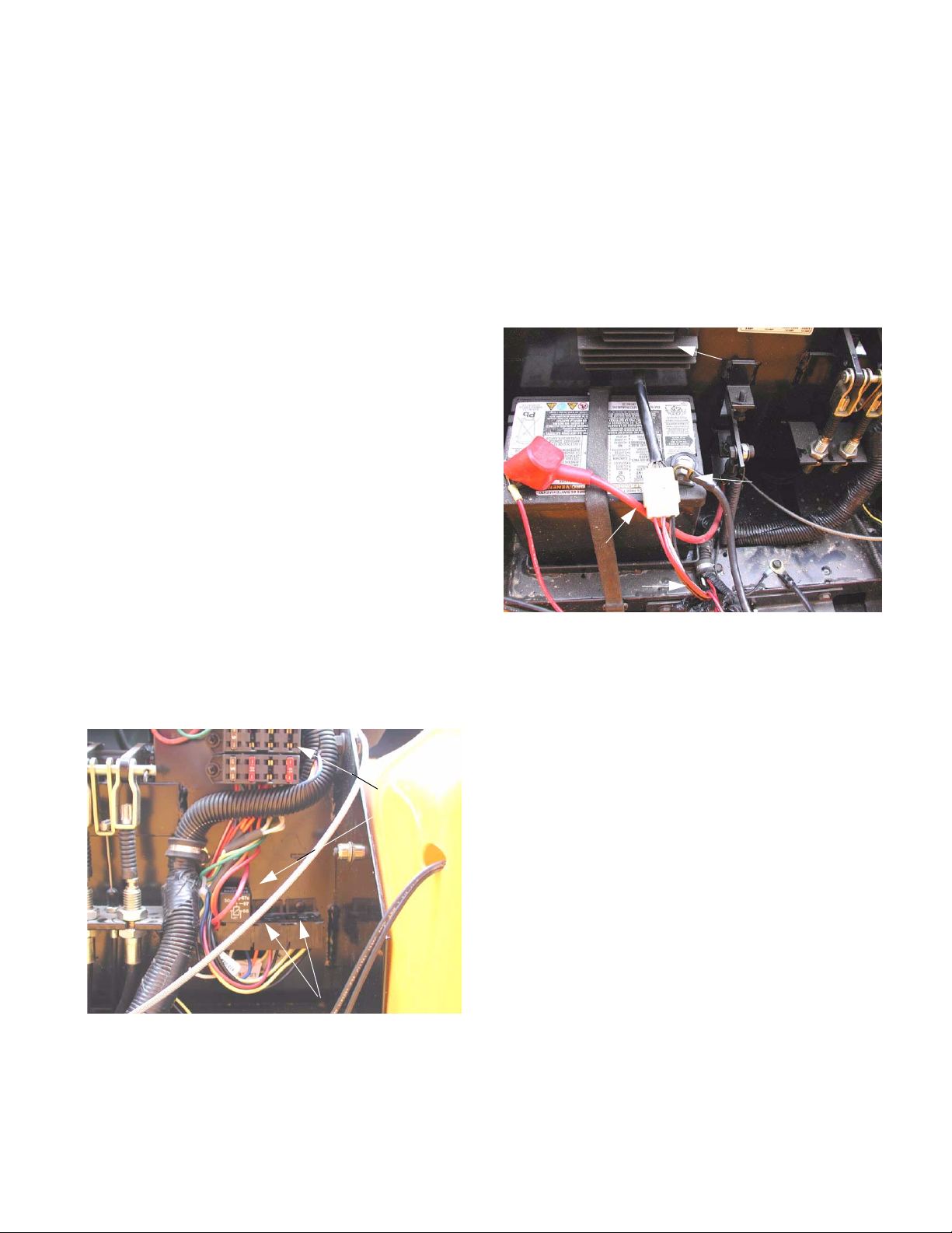
1.3. Vehicles equipped with the wiring harness that is
subject to his occurrence are readily identifiable
by the location of the fuse box, relays and voltage regulator-rectifier. The fuse box is mounted
under the hood in a vertical position on driver’s
side of the firewall. Directly beneath it are
molded plugs for three relays. The regulatorrectifier is located under the hood on the passenger’s side firewall, directly above the battery. See Figure 1.3.
1.4. If not equipped with the effected harness further
diagnosis is necessary. If equipped with the
effected harness, disconnect the negative battery cable using a 7/16” wrench.
1.5. Unplug the harness connector from the pigtail on
the regulator-rectifier. See Figure 1.5.
Regulator rectifier
Negative
battery cable
Harness
plug
Cut here
Figure 1.5
1.6. Cut the two red wires that enter the harness
connector roughly 6” from the connector.
NOTE: It may be necessary to remove some of
the protective covering (conduit) from the harness.
Bed lift relay location
Figure 1.3
K&T Saw Shop 606-678-9623 or 606-561-4983
Fuses
Accessory
Relay
1.7. Strip 1/4” of insulation from the loose ends of the
red wires that are attached to the harness plug.
1.8. Twist the stripped ends together, and crimp them
securely into the yellow butt connector.
1.9. Strip 1/2” of insulation from the end of the red
wire provided in the kit.
1
Page 6

www.mymowerparts.com
Big Country 6 x 4 and 4 X 2 Update
1.10. Fold the stripped end back on itself, and crimp it
securely into the other end of the yellow butt
connector. See Figure 1.10.
Harness
connector
2 Original
red wires
Yellow butt
connector
New red wire
Figure 1.10
1.11. Remove the accessory relay from the relay block
on the firewall. See Figure 1.11.
1.14. Strip 1/4” of insulation from the ends of the two
lengths of white wire and 1/2” of insulation from
the loose end of the red wire that was previously
added to the harness connector.
1.15. Twist the two stripped ends of the white wire
together and crimp them securely into the second yellow butt connector.
1.16. Fold the stripped end of the red wire back on
itself, and crimp it securely into the other end of
the yellow butt connector. See Figure 1.16.
White
wires
Yellow butt
connector
Red
wire
Accessory relay
Mounting
White wire
Figure 1.11
1.12. Remove the relay block from the firewall using a
phillips head screwdriver, and separate it from
the other two relay blocks.
NOTE: The relay blocks have interlocking channels on each side.
1.13. Cut the white wire that enters the accessory
relay block. Leave enough length accessible on
each side of the cut to strip the insulation from
the wire and install a butt connector.
crews
Figure 1.16
1.17. Install the relay block back on the firewall, and
plug-in the relay.
1.18. Plug the voltage regulator-rectifier connector
back into the harness connector.
1.19. Connect the negative battery cable to the negative battery terminal.
1.20. Close and secure the hood.
1.21. Test-run the Big Country 6 X 4 before returning it
to service.
NOTE: It may be necessary to remove some of
the protective covering (conduit) from the harness.
K&T Saw Shop 606-678-9623 or 606-561-4983
2
Page 7
www.mymowerparts.com
Big Country 6 x 4 and 4 X 2 Update
2. ISSUE: REVERSED OPERATION OF ACCESSORY (BED LIFT) SWITCH (CC 438)
Some first-year production Big country Utility Vehicles
(after serial number 1A013B000001) may have been
made with mis-wired accessory connectors in the wiring harness. If this situation exists, rocking the bed lift
switch up will lower the bed, and rocking the bed lift
switch down will tilt the bed. If a customer has complained of this situation, the following change should be
made to the wiring harness:
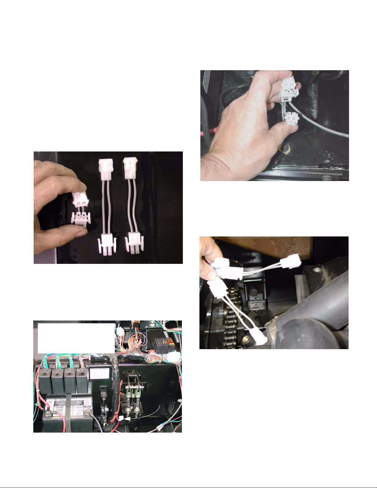
2.1. The service kit consists of three adaptors that
reverse the polarity of the connections.
See Figure 2.1.
Three adaptors
contained in
CC348 kit
2.4. Install one adaptor from the service kit as an
interface connector between the harness and
the accessory. See Figure 2.4.
Figure 2.4
2.5. Raise the bed. The final two connectors are
located among the bundle near the right rear
corner of the engine compartment, at the top of
the frame. See Figure 2.5.
Figure 2.1
2.2. Remove the two wing screws that secure the
hood, and open the hood.
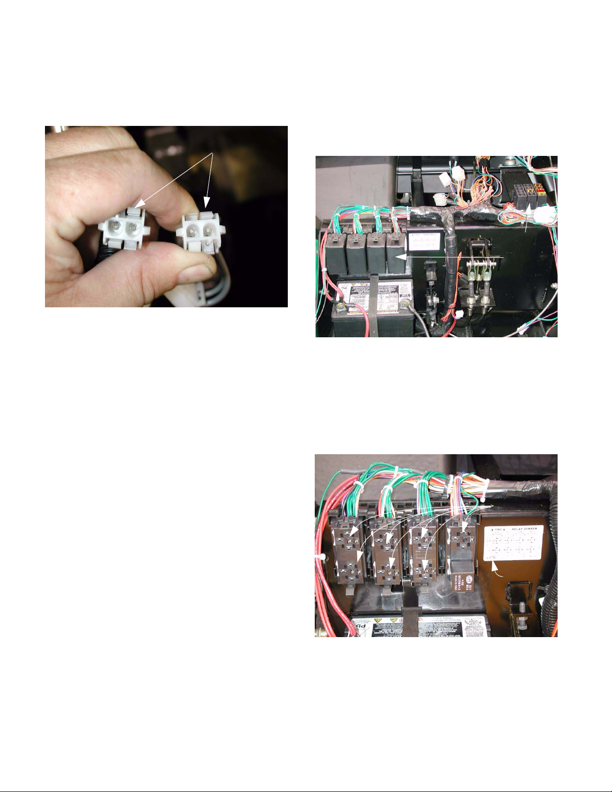
2.3. Identify the front accessory relay connector.
See Figure 2.3.
The front accessory relay
connector has one red wire
and one red wire with a
white trace.
Front
accessory
relay
connector
Figure 2.3
Figure 2.5
2.6. Identify the connector that joins the lift motor to
the lift motor relays. It has one red wire and
one yellow wire. Install the second adaptor as
an interface connector between the lift motor
and the harness connection to the lift motor
relays.
2.7. Identify the rear accessory relay connector, and
install the third adaptor to it in similar fashion to
the first two adaptors. The rear accessory relay
connector has one purple wire and one black
wire.
3
K&T Saw Shop 606-678-9623 or 606-561-4983
Page 8
y
_
www.mymowerparts.com
Big Country 6 x 4 and 4 X 2 Update
2.8. The adaptors will reverse the polarity of the connections. If reveres action of accessories or bed
lift is not encountered, the adaptors are not necessary on that unit. See Figure 2.8.
Polarity reversed
Figure 2.8
2.9. Lower the bed. Close and secure the hood.
2.10. Test the operation of the bed lift and accessories
before returning the unit to service.
3. FEATURE: NEW WIRING HARNESS
3.1. The relays have been consolidated into a relay
center above the battery, in the place formerly
occupied by the voltage regulator-rectifier. The
fuse block has been moved from the vertical surface of the firewall. See Figure 3.1.
Fuse block
Relay
center
Figure 3.1
NOTE: The 4 X 2 and 6 X 4 use the same wiring
harness after serial number 1A013B000001. the
features listed apply to both models.
3.2. The relays and their sockets in the relay centered protected by plastic covers.
See Figure 3.2.
Accessory relay
sockets (covers
off)
Key to rela
center
Figure 3.2
4
K&T Saw Shop 606-678-9623 or 606-561-4983
Page 9

www.mymowerparts.com
Big Country 6 x 4 and 4 X 2 Update
3.3. One relay in this block is used by the original
equipment. The rest of the sockets accommodate pre-wired accessories. See Figure 3.3.
Detail of key to relay center
Figure 3.3
3.4. The relay covers go on in one direction only.
There is a notch in each cover that matches a
notch in the relay socket. See Figure 3.4.
3.5. The one relay that is not in this group is the
starter relay, which is located on the outside of
the harness, just below the center of the upper
cross-member at the front of the engine compartment. See Figure 3.5.
Figure 3.5
NOTE: The starter relay is different from the
other relays on the Big country 6 X 4, but is interchangeable with the relays used on the 2000
series, 3000 series, and the recent 1000 series.
Wrong
Figure 3.4
Right
3.6. The fuse block has been moved to the horizontal
surface at the top of the firewall on the driver’s
side of the vehicle. See Figure 3.6.
Fuse
block
Dashboard
Front of vehicle
Key to
fuse block
Figure 3.6
5
K&T Saw Shop 606-678-9623 or 606-561-4983
Page 10

www.mymowerparts.com
Big Country 6 x 4 and 4 X 2 Update
3.7. The fuse block also contains capacity for expansion, allowing the easy addition of accessories
See Figure 3.7.
Detail of key to fuse block
Figure 3.7
3.8. The voltage regulator-rectifier has been relocated to the right side of the cross-member at
the top front corner of the engine compartment.
See Figure 3.8.
3.10. The 4 X 2 and the 6 X 4 use the same wiring harness. The 6 X 4 has a mechanical gear selector
system while the 4 X 2 has an electrically controlled, vacuum actuated gear selector system.
The harness connections that join the push-button gear selector to the main harness in the 4 X
2 exist in the 6 x 4 as well. They are secured
behind the dashboard, but are not connected to
anything. See Figure 3.10.
Blanks for accessory
switches
4 X 2
gear
selector
button
holes
Controller and buttoner
connections for 4 x 2
gear selector
Figure 3.10
Instrument panel
Regulator / Rectifier
Figure 3.8
3.9. The instrument panel has been revised slightly,
and may be further revised for ‘04 production.
4. FEATURES: GENERAL IMPROVEMENTS
NOTE: Most of the features listed in this section
are present on the 4 X 2 and the 6 X 4. Lessons
learned in the first year of production have been
applied to all models.
4.1. Suspension travel has been increased.
See Figure 4.1.
Old front
suspension
travel
New front
suspension travel
Figure 4.1
6
K&T Saw Shop 606-678-9623 or 606-561-4983
Page 11
www.mymowerparts.com
Big Country 6 x 4 and 4 X 2 Update
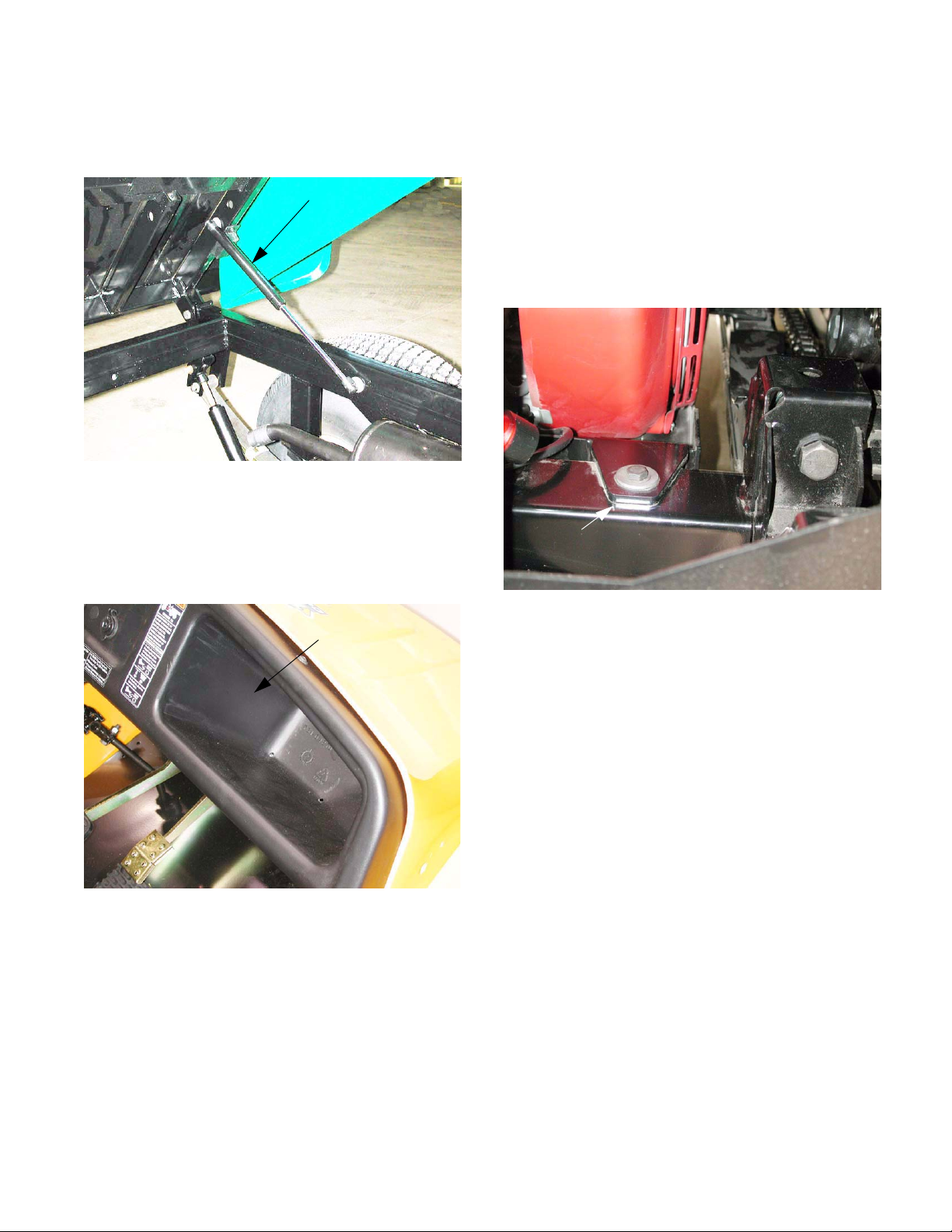
4.2. The manually operated lift bed now features a
gas charged lift assist cylinder on the 6 X 4 as
well as the 4 X 2. See Figure 4.2.
Lift cylinder
Figure 4.2
4.3. The heat shield will move from the bed to the
muffler tor reduce vibration noise.
4.4. The dashboard and glove box are now a single
piece instead of two. See Figure 4.4.
Integrated
dashboard and
glove box
4.6. The two mounting systems are not interchangeable. The rear mounting points on the frame are
not drilled and cut to accept the rubber isolator
mounts. The front mounting points have
changed substantially. Inserting rubber isolator
mounts between the frame and the the engine
and transmission support bracket on a Big
Country 6 X 4 that was not meant to have them
will also create clearance issues between the
bed and the intake system. See Figure 4.6.
Solid rear mounting point
Figure 4.6
NOTE: The solid mounts may allow slightly
higher vibration at idle than the rubber mounts.
Figure 4.4
4.5. The engine and transmission support bracket (6
X 4) are solid mounted to the frame. Early versions (prior to serial number 1A013B000001)
used rubber isolated engine and transmission
support brackets. The solid mountings maintain
more consistent alignment between the transmission and the suspension. Mis-alignment
allows drive-shaft whip, causing vibration under
load, and accelerated wear.
4.7. All of this year’s production will have the smaller
headlights with better optics than last year. This
was a running change during ‘03 model year
production.
7
K&T Saw Shop 606-678-9623 or 606-561-4983
Page 12

www.mymowerparts.com
Big Country 6 x 4 and 4 X 2 Update
4.8. This year’s fenders will also be high-cut compared to last year’s fenders. This was a running
change during ‘03 model year production.
See Figure 4.8.
Figure 4.8
4.9. A seal has been added to the rear edge of the
hood.
4.12. Last year, if the optional brush guard was fitted,
it was necessary to remove it before opening the
hood. See Figure 4.12.
Figure 4.12
4.13. The new hood is mounted on a bracket that
slides into brackets on the frame, rather than a
piano hinge previously used. See Figure 4.13.
4.10. A more subtle change to the front fenders
involves the contour where the hood meets the
fender. The previous fender did not have the
extra ridge to help locate the edge of the hood.
See Figure 4.10.
Contour added for the edge of the
hood to seat in
Figure 4.10
4.11. Mossy Oak
flage will be an available finish for bodywork on
the Big country.
TM Dark Forrest Floor Pattern camou-
Frame bracket
Slide to remove
hood bracket
Figure 4.13
4.14. The pin is retained by a washer and hairpin clip.
Remove hairpin clip
and washer
8
K&T Saw Shop 606-678-9623 or 606-561-4983
Page 13

www.mymowerparts.com
Big Country 6 x 4 and 4 X 2 Update
4.15. The bed of the 4 X 2 is rated to carry 800 lbs, as
opposed to 1,000 lbs for the 6 X 4. The 4 X 2
bed is 39” long (internal) compared to 47” (internal) for the 6 X 4. See Figure 4.15.
Figure 4.15
4.16. The tailgate of the 4 X 2 bed differs from that of
the 6 X 4 in that of the 6 X 4 in that it is held in
place by 4 J-pins. See Figure 4.16.
4.17. It can be released at the top for loading or dumping. See Figure 4.17.
Tailgate bumpers
Tailgate lanyard
Figure 4.17
4.18. If the operator wishes to spread the contents of
the bed, the two bottom J-pins can be released.
This will allow the bottom of the tailgate to swing
away from the bed, while the top edge remains
fixed. See Figure 4.18.
J-pins
Figure 4.16
Figure 4.18
9
K&T Saw Shop 606-678-9623 or 606-561-4983
Page 14

www.mymowerparts.com
Big Country 6 x 4 and 4 X 2 Update
4.19. Travel limiters are installed on the 4 X 2 bed
hinge point to keep the bed from tilting beyond
the intended range. Under no circumstances
should a Big Country 4 X 2 be placed in service
without those components in place.
See Figure 4.19.
Travel limiter
Figure 4.19
4.20. There have been some complaints of rattling tailgates. This issue will be addressed for ‘04 production.
4.23. For ‘04, the structure of the frame forward of the
engine bay will change. Instead of one hollow
channel beneath the floor, three separate channels will increase the rigidity of the structure.
Suspension pick-up points and mounting locations will remain unchanged. Some firewall
bracketry will be simplified. See Figure 4.23.
4.24. The pedal mounting brackets will also be simplified. See Figure 4.24.
Figure 4.23
4.21. For ‘04, the 4 X 2 Big Country will use a cable
operated shift mechanism instead of the electrically controlled, vacuum operated system currently in place.
4.22. The electrically controlled, vacuum operated differential lock will remain for the ‘04 season.
Figure 4.24
4.25. For ‘04, the front wheel mounting (lugs) and size
may be standardized to match the rear wheels.
4.26. For ‘04, the hood will be held down with a rubber
strap fastener. This will eliminate easy-to-lose
wing bolts, and it will hold the hood more firmly
in position.
10
K&T Saw Shop 606-678-9623 or 606-561-4983
Page 15

www.mymowerparts.com
5. OPENING PRICE POINT
5.1. An OPP (opening price point) version of the 4 X
2 will be introduced for the 2004 model season.
5.2. It will use the same platform as the standard 4 X
2, with the possible exception of closed panels
on the side. See Figure 5.2.
Big Country 6 x 4 and 4 X 2 Update
Figure 5.2
5.3. The opening price point model may have a polymer bed.
5.4. The opening price point model may have four
four-bolt wheels. They will be smaller than those
found on the heavy duty 4 X 2.
5.5. Turf tread may be the only tire available for the
OPP model.
5.6. The opening price point model may feature a
translucent fuel tank.
5.7. The opening price point model will have a 9.5
H.P. single-cylinder Kawasaki engine and transaxle.
5.8. The engine and transmission cradle (OPP only)
will be changed to fit the Kawasaki drive train.
5.9. The rear spring rates of the OPP model will be
changed to reflect lighter usage.
5.10. The wiring harness will be pared-down for the
OPP model. Accessory harnesses must be
added for accessories.
11
K&T Saw Shop 606-678-9623 or 606-561-4983
 Loading...