

Page 1
BDU-10/21
Hydrostatic Transmissions
Service and Repair Manual
BLN-50327
January 2009
Page 2

BDU-10/21
Table of Contents
Table of Contents
Description Page
Introduction ......................................................................................................3
General Description.......................................................................................3-5
Fluids...............................................................................................................6
Safety Precautions ...........................................................................................6
Maintenance....................................................................................................6
Troubleshooting Diagram.................................................................................. 7
Troubleshooting Chart....................................................................................... 8
Minor Repairs ............................................................................................. 9-14
General Information......................................................................................9
Shaft Seals............................................................................................. 9-10
Charge Check V alves.............................................................................10-11
Bypass Valves ............................................................................................11
Easy Ride V alves ........................................................................................11
Charge Pumps ..................................................................................... 12-14
Major Repairs ........................................................................................... 14-21
General Information.................................................................................... 14
Disassembly Procedures....................................................................... 15-17
Reconditioning & Replacement of Components ............................................ 17
Assembly Procedures ........................................................................... 17-21
BDU-10S Parts Drawing & Parts List........................................................... 22-23
BDU-10L Parts Drawing & Parts List. .......................................................... 24-25
BDU-21L Parts Drawing & Parts List. .......................................................... 26-27
Page 2
BDU-10/21
Page 3
Introduction/General Description
Introduction
BDU-10/21
The purpose of this manual is to provide information useful
in servicing the BDU Hydrostatic Transmission product
line. This manual includes unit and component description, troubleshooting, maintenance, and repair procedures.
A transmission normally will not require servicing, other
than the vehicle manufacturer’s recommended fluid and
filter changes during the life of the vehicle in which it is
installed. Should other servicing be required, the unit must
be removed from its installed location and thoroughly
cleaned before beginning most procedures.
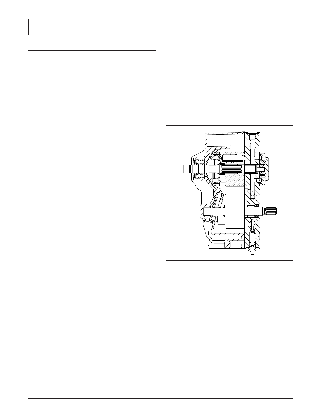
General Description
The BDU Hydrostatic Transmission is designed for the
transfer and control of power. It provides an infinitely
variable speed range between zero and maximum in both
forward and reverse modes of operation. The BDU transmission can be mounted to a variety of transaxles including
most HYDRO-GEAR models.
The BDU transmission is a “U” style transmission with a
variable displacement pump and a fixed displacement
motor. The variable displacement pump features a cradle
swashplate with a direct-proportional displacement control. Reversing the direction of tilt of the swashplate
reverses the flow of oil from the pump and thus reverses the
direction of the motor output rotation. The fixed displacement motor uses a fixed swashplate. The pump and motor
are of the axial- piston design and utilize spherical- nosed
pistons which are held against a thrust race by internal
compression springs.
The fluid supply for the BDU-10L/21L transmission is
contained in an external reservoir and passes through an
external filter prior to entering the transmission and feeding
the fixed displacement gerotor charge pump. Excess fluid
in the charge circuit is discharged over the charge relief
valve back to the charge pump inlet. Constant flow across
a small fixed orifice connecting the charge circuit to the
transmission housing supplements the cooling flow.
BDU-10L Transmission
The BDU-10S transmission has a self-contained fluid
supply and an integral filter. The fluid is forced through the
filter by positive “head” on the fluid in the housing/reservoir
with an assist by the negative pressure created in the pump
pistons as they operate.
BDU-10/21
Charge check valves in the center section are used to
control the makeup flow of fluid to the low pressure side of
the loop.
A spool type bypass valve is utilized in the transmission to
permit moving the vehicle for short distances at low speeds
(2mph) (3.2 km/hr) without starting the engine.
Page 3
Page 4

BDU-10/21
The BDU-21L transmission offers an optional Implement
(auxiliary) pump. The auxiliary circuit provides a rated flow
of 1.5 gpm (5.67 l/min) and 500 PSI (34.5 bar) operating
pressure at a 3200 RPM pump speed.
Fluid from the charge pump flows first to the implement
control valve, then to the charge relief valve and charge
check valves in the center section. This requires an “open
center” type control valve to allow fluid flow to return to the
transmission. A check valve is included to allow oil to be
drawn into the charge circuit should flow returning from the
implement circuit be insufficient to charge the closed loop.
A relief valve must be included in addition to the implement
control valve.
The BDU-21L offers an Easy Ride Valve option. The Easy
Ride Valve acts like a high pressure spike suppressor in
the system loop. The valve opens under high acceleration
loads. The result is a dampening of the aggressiveness,
without affecting the overall efficiency of the transmission.
General Description
BDU-21L Transmission with Easy Ride Valve
Option
BDU-10S Hydrostatic Flow Illustration
BDU-10/21Page 4
Page 5
General Description
BDU-10/21
BDU-10L/21L Hydrostatic Flow Illustration
BDU-21L/A Hydrostatic Flow Illustration
BDU-10/21
Page 5
Page 6

BDU-10/21
Maintenance
Fluids
The fluids used in HYDRO-GEAR products have been
carefully selected, and only equivalent, or better products
should be substituted.
Typically, an engine oil with a minimum rating of 9.0 cSt
(55 SUS) at 230°F (110°C) and an API classification of SJ/
CD is recommended. A 20W-50 engine oil has been
selected for use by the factory and is recommended for
normal operating temperatures. For colder climate operation (see chart), a change to a 10w-40 engine oil may be
necessary. Another alternative that will provide excellent
all climate performance and extended time between oil
changes is a 15W-50 synthetic engine oil.
SAE VISCOCITY GRADES
20W-50
10W-40
15W-50 Synthetic
-35
o -5o
AMBIENT AIR TEMPERATURE oF
15o 60
o
100
o
Maintenance
Check the transmission cooling fan for broken or distorted
blades, and check to see that the fan is securely fastened.
Replace the fan if damaged.
Keep the transmission clean. Grass clippings and dirt will
influence the cooling efficiency of the fins on the transmission housings. Avoid high pressure fluid washes, compressed air is the preferred method of removing loose
debris. Avoid the immediate area of the lip seals or damage
may occur.
Check to make sure the bypass valve and linkage is
operational. The bypass valve should be fully released
before operating the vehicle. It should extend approximately 0.22" (5.588mm) from the hex nut.
Inspect the transmission for leaks at the lip seals, damage
to fittings, hoses, the filter, or to the housings. Check the
oil level and add oil as necessary to bring it up to the proper
level. Refer to vehicle owners manual.
Safety Precautions
Certain procedures may require the vehicle to be disabled
(wheels raised off the ground, engine disconnected, etc.)
in order to prevent possible injury to the technician and
bystanders.
Some cleaning solvents are flammable. To avoid possible
fire, do not use cleaning solvents in an area where a source
of ignition may be present.
The loss of hydrostatic driveline power may result in the
loss of hydrostatic braking capacity. Proper brake maintenance becomes very important should this condition
develop.
BDU-10L
BDU-21L/A
BDU-10/21Page 6
Page 7
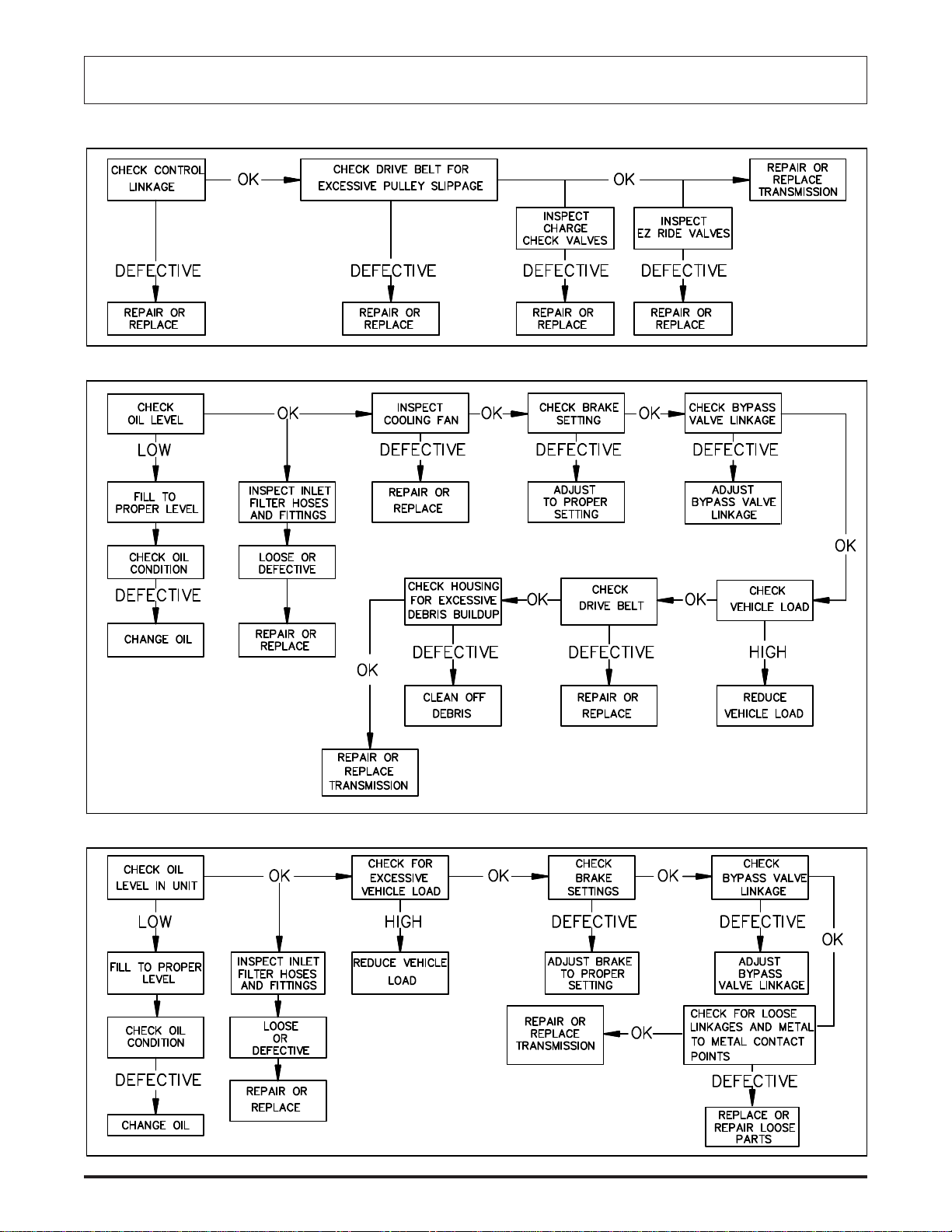
Troubleshooting Diagram
OPERATES IN ONE DIRECTION ONLY
OPERATING HOT/LOSING POWER
BDU-10/21
BDU-10/21
NOISY UNDER LOAD
Page 7
Page 8

BDU-10/21
Troubleshooting Chart
WARNING!!!
THE VEHICLE SHOULD BE ON LEVEL GROUND AND
THE ENGINE DISABLED BEFORE PERFORMING ANY ADJUSTMENTS
SYMPTOM - OPERATES IN ONE DIRECTION ONLY
POSSIBLE CAUSE CORRECTIVE ACTION
-Inspect control linkage -Repair or replace
-Inspect drive belt & pulleys -Repair or replace
-Inspect check valves -Repair or replace
-Inspect easy ride valves -Repair or replace
SYMPTOM - NOISY
POSSIBLE CAUSE CORRECTIVE ACTION
-Check oil level & condition -Fill to proper level or change oil
-Check for excessive loading -Reduce vehicle loading
-Check brake setting -Adjust brake to proper setting
-Check for loose parts -Repair or replace loose parts
-Check bypass valve operation -Repair or replace valve or linkage
-Check inlet flow conditions -Repair or remove obstruction or leaks
-Inspect check valves -Repair or replace
-Inspect easy ride valves -Repair or replace
-Inspect auxillary circuit -Repair or replace
SYMPTOM - LOW POWER
POSSIBLE CAUSE CORRECTIVE ACTION
-Check engine RPM -Adjust to correct setting
-Check drive belt & pulleys -Repair or replace
-Check oil level & condition -Fill to proper level or change oil
-Check for excessive loading -Reduce vehicle loading
-Check brake setting -Adjust brake to proper setting
-Check for loose parts -Repair or replace loose parts
-Check bypass valve operation -Repair or replace valve or linkage
-Check inlet flow conditions -Repair or remove obstruction or leaks
-Check operating temperature -Repair or replace unit
-Inspect check valves -Repair or replace
-Inspect easy ride valves -Repair or replace
-Inspect auxillary circuit -Repair or replace
SYMPTOM - OPERATING HOT
POSSIBLE CAUSE CORRECTIVE ACTION
-Check bypass valve operation -Repair or replace
-Check for debris buildup -Clean off debris
-Check oil level & condition -Fill to proper level or change oil
-Check for excessive loading -Reduce vehicle loading
-Check brake setting -Adjust brake to proper setting
-Check cooling fan for damage -Repair or replace
-Inspect check valves -Repair or replace
-Inspect easy ride valves -Repair or replace
-Inspect auxillary circuit -Repair or replace
Page 8
BDU-10/21
Page 9
Minor Repair
Minor Repair
BDU-10/21
General Information
Minor repairs may be performed, following the procedures
in this section, without voiding the unit warranty.
Cleanliness is a primary means of assuring satisfactory life
on either new or repaired units. Cleaning parts by using
solvent wash and air drying is usually adequate. As with
any precision equipment, all parts must be kept free of
foreign materials and chemicals.
Protect all exposed sealing surfaces and open cavities
from damage and foreign material. The outer surfaces must
be cleaned before beginning any repairs.
It is recommended that all O-rings and seals be replaced.
Lightly lubricate all O-rings and seals with a clean petroleum jelly prior to assembly.
Plug/Fitting Torques
If any plugs were removed during servicing, they should be
torqued as indicated in the accompanying table:
Shaft Seals
Lip type seals are used on the pump input shaft, pump
through shaft (not all models use the through shaft), motor
output shaft and displacement control shaft. These seals
can be replaced without major disassembly of the unit.
However, replacement of the seals generally requires
removal of the transmission from the machine.
To replace the pump input shaft seal, first remove the
retaining ring from the housing.
Carefully pull the seal out of the housing bore. A “hook” type
tool may be used to grasp the seal and pull it out, or a slide
hammer type puller may be used to remove the seal. Care
must be taken so as not to damage the housing bore, shaft
sealing surface, or bearing. Once removed, the seal is not
reusable.
NOITAREPOEUQROTNOITPIRCSEDTRAP
gulPssapyB
)s(gulPkcehC
gulPedirysaE
gnittiF/gulPleetS
01(
gnittiF/gulPleetS
gnittiF/gulPleetS
gnittiF/gulPleetS
bl042-081
SNOITACIFICEPSEUQROT
nibl021-48
)mN5.31-5.9(
nibl042-081
)mN72-02(
nibl042-081
)mN72-02(
nibl021-69
)mN5.31-8.
nibl042-081
)mN72-02(
ni
)mN72-02(
nibl042-081
)mN72-02(
SEAS81-61/9
daerhTthgiartSEAS02-61/7
Retaining Ring Removal
daerhTthgiart
daerhTthgiartSEAS61/9
daerhTthgiartSEAS61/7
daerhTthgiartSEAS61/9
daerhTthgiartSEAS4/3
daerhTthgiartSEAS8/7
Lip Seal Removal
BDU-10/21
Page 9
Page 10

BDU-10/21
Minor Repair
Shaft Seals
Inspect the sealing area on the shaft for rust, wear, or
contamination. Polish the sealing area on the shaft if
necessary.
Wrap the spline or keyed end of the shaft with with a thin
plastic or cellophane to prevent damage to the seal lip
during installation.
Lubricate the new seal with petroleum jelly and slide the
seal over the shaft and press it into the housing bore. Be
careful not to damage the seal.
Install the retaining ring in the housing.
The pump through shaft, motor output shaft and displace-
ment control shaft may be replaced following a similar
procedure as outlined for the pump input shaft seal. These
seals are not held in position by a retaining ring.
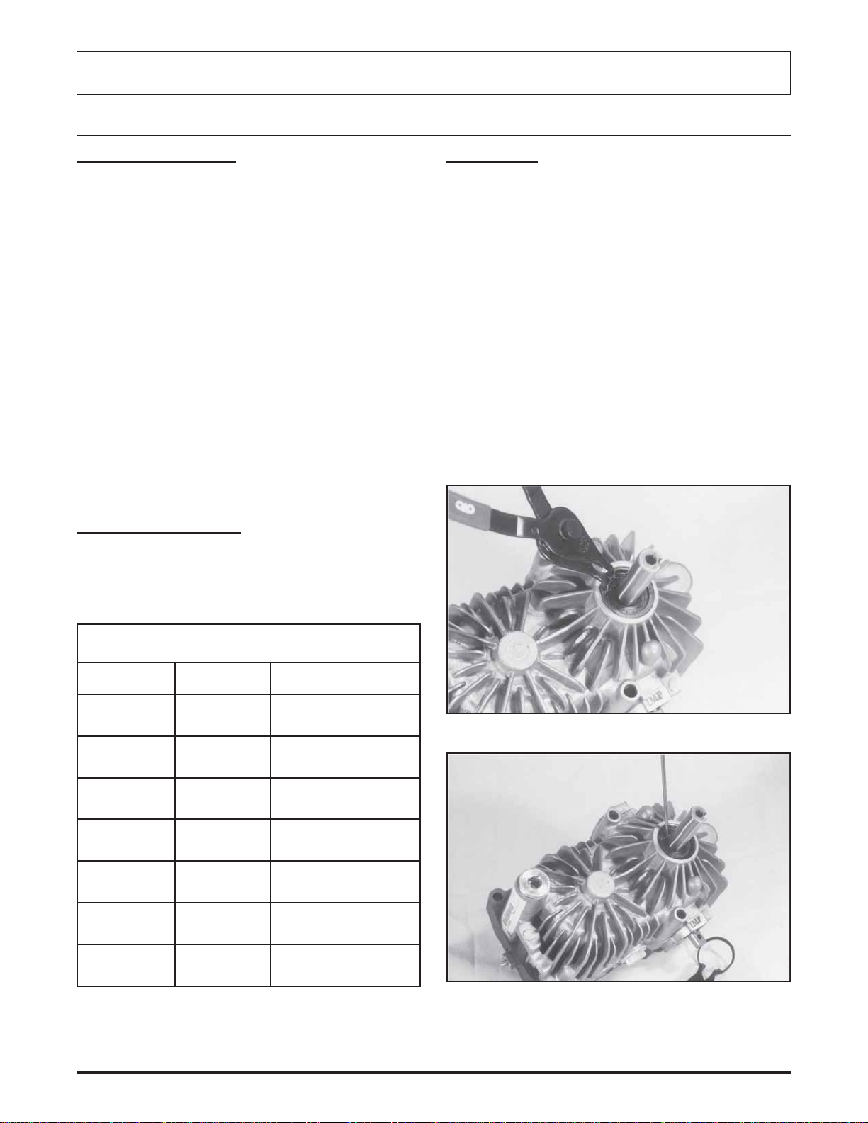
Charge Check Valves
Remove the check valve plug with a 1/4" internal hex
wrench.
Remove the check valve spring and check ball (or poppet)
from the center section.
CAUTION: Do not allow the check ball to fall into the
closed loop passages in the center section. Removal
may be difficult but can be accomplished with a
magnet, or by removing the plug from the end of the
center section. Do not allow contaminants to be
introduced to the system.
Lip Seal Installation
Retaining Ring Installation Check Valve Options
Page 10
Check Valve Removal/ Installation
BDU-10/21
Page 11

BDU-10/21Minor Repair
Inspect the check balls (or poppets) and mating seats in
the center section for damage or foreign material.
Position the transmission so that the check valve port will
be in the upright position (as shown) and install the check
ball (or poppet), spring and plug (with o-ring) into the center
section. Make sure the plug stem is properly positioned
into the poppet or damage and failure will occur. Be certain
the check ball does not fall into the closed loop passage.
Torque the plug to 15-20 ft.lbs (20-27 Nm).
Turn the unit over and repeat the procedure for the other
side.
Bypass Valve
Remove the bypass valve plug with a 9/16" hex wrench.
Retain the valve spring to the valve spool with petroleum
jelly. Install the valve spool, spring and plug (with o-ring)
into the center section. Torque the plug to 7-10 ft.lbs.
(9.5-13.5 Nm).
Depress the bypass valve several times to insure that it
operates smoothly and fully closes. The bypass “button”
should extend from the hex plug approximately 0.22"
(5.588 mm) when fully released (closed).
Easy Ride Valves
Remove the Easy Ride valve plug with a 11/16" open end
wrench or socket.
Remove the spring, piston and sleeve from the center
section.
Inspect the piston nose for damage.
Inspect the piston sleeve and spring for damage. The
piston should slide freely in the sleeve, but should fit tight
enough to create a vacuum.
Remove the bypass valve plug, spool and spring from the
transmission center section.
Inspect the valve spool and mating bore in the center
section for damage or foreign material. The spool must
move freely. It is recommended that the o-rings be replaced.
Inspect the valve seat in the center section for damage. If
the valve seat is damaged the center section must be
replaced. Refer to the Major Repair section of this manual.
Install the piston, sleeve and valve spring.
Install the hex plug and torque to 15-20 ft.lbs. (20-27 Nm).
Bypass Valve Easy Ride Valve
BDU-10/21
Page 11
Page 12

BDU-10/21
Charge Pump
Minor Repair
The correct charge pump orientation is determined by the
rotation of the pump shaft (CW or CCW). Before removing
the charge pump, make note of, and/or mark its position to
simplify the reassembly process.
BDU-10L CCWBDU-10L CW
NOTE: Unlike the BDU-10L, some BDU-21L transmis-
sions have an implement circuit designed into the charge
pump cover. These covers are different and are
reversible. It is very important that they are reassembled in
the same orientation as they were removed.
BDU-10L With Through Shaft Charge Pump
not
BDU-21L CW
Page 12
BDU-21L Aux. CW
BDU-21L Aux. CCWBDU-21L CCW
BDU-10/21
Page 13

Minor Repair
BDU-10/21
Disassembly Procedures
Using a 5 or 6mm internal hex wrench, remove the two (2)
screws holding the charge pump cover to the center
section.
Remove the charge pump cover and o-ring. Avoid turning
or twisting the charge cover during removal, or damage
to the charge relief valve spring may occur.
Remove the charge pump gerotor assembly.
For BDU-21L with implement circuit: Remove the
charge pump shim, two aligning pins, two o-rings, the
gerotor assembly and the charge pump drive pin. Make
note of the top and/or bottom of the gerotor assembly.
For BDU-21L: Remove the charge pump drive pin.
For BDU-10L with a through shaft: Remove the charge
pump drive pin, spacer plate and o-ring. Make note of the
top and/or bottom of the spacer plate.
Remove the charge relief valve spring and ball.
For BDU-21L: Install the charge relief valve spring and ball.
Install the drive pin. Install the gerotor assembly. Install a
new o-ring and the charge pump cover. NOTE:The charge
relief spring must enter the recessed hole in the charge
pump cover. Torque the bolts evenly to 12-15 ft.lbs.
(16.3-20.3 Nm).
BDU-10L Charge Pump Components
NOTE: The BDU-21L with implement circuit has the charge
relief valve spring and ball in the charge pump cover.
Inspect the gerotor assembly, charge pump cover, and
center section (or spacer plate) for abnormal wear, damage
or foreign material. Inspect the charge relief valve ball and
spring. Inspect the charge relief valve seat in the center
section for damage or foreign material.
Assembly Procedures
Prior to reassembly of the charge pump, apply a small
quantity of petroleum jelly to the I.D., O.D., and faces of the
gerotor assembly.
NOTE: Improper assembly of the charge relief valve spring
and ball, or the incorrect orientation of the charge cover will
cause a priming failure. If assembled properly, the charge
pressure should be maintained at 25 to 70 PSI
(1.72-4.82 bar) at 3000 RPM pump speed.
For BDU-10L Install the charge relief valve spring and ball.
Install the gerotor assembly. Install a new o-ring and the
charge pump cover. NOTE:The charge relief spring must
enter the recessed hole in the charge pump cover. Torque
the bolts evenly to 7-10 ft.lbs. (9.5-13.5 Nm).
BDU-10L Through Shaft Charge Pump Components
For BDU-10L models with through shaft: Install the
charge relief valve spring and ball. Install a new o-ring and
the spacer plate onto the aligning pins paying attention to
the correct orientation. NOTE:The charge relief spring
must enter the recessed hole in the spacer plate. Install the
charge pump drive pin. Install the gerotor assembly. Install
a new o-ring and charge pump cover. Torque the bolts
evenly to 7-10 ft.lbs. (9.5-13.5 Nm).
BDU-10/21
Page 13
Page 14

BDU-10/21
Major Repair
Charge Pump
Assembly Procedures
For BDU-21L with implement circuit: Install the drive
pin. Install a new o-ring on each side of the gerotor
assembly and position the gerotor assembly onto the
aligning pins in the same orientation as it was removed.
Install the charge pump shim and the charge pump cover.
Torque the bolts evenly to 18-25 ft.lbs.(24.4-33.9 Nm).
Major Repair
General Information
Major repairs described in the following sections are for the
complete disassembly and reassembly (Major Repair) of
the transmission and will void all product warranty, unless
license to perform said major repairs was previously
obtained from an authorized representative of HYDROGEAR.
Cleanliness is a primary means of assuring satisfactory life
on repaired units. Cleaning parts by using solvent wash
and air drying is usually adequate. As with any precision
equipment, all parts must be kept free of foreign materials
and chemicals.
Protect all exposed sealing surfaces and open cavities
from damage and foreign material. The outer surfaces
should be cleaned before beginning any repairs.
It is recommended that all O-rings and seals be replaced.
Lightly lubricate all O-rings and seals with a clean petroleum jelly prior to assembly.
BDU-21L Charge Pump Components
BDU-21L/A CW Charge Pump Components
It is recommended that parts requiring replacement be
replaced with the complete assembly (kit) as shown in the
service parts drawings on pages 22-27.
Prior to performing major repairs on the BDU Hydrostatic
Transmission, remove the transmission from its installed
location and remove any external components such as a
cooling fan and input pulley or frame mounting hardware.
NOTE: Thoroughly clean all exposed surfaces prior to any
further disassembly.
Remove the oil lines (hoses and fittings) so that as much
oil as possible can be drained from the housing.
BDU-21L/A CCW Charge Pump Components
BDU-10/21Page 14
Page 15

Disassembly Procedures
Prior to performing major repairs on the BDU remove the
external components as described in the Minor Repairs
section of this manual. These include the following:
Bypass Valve
Charge Check Valves
Charge Pump Assembly
Using a 6 mm internal hex wrench, remove the eight
screws which retain the center section to the housing.
BDU-10S Center Section Removal
The internal springs of the pistons should separate the
center section from the housing. Remove the center
section from the housing.
BDU-10/21Major Repair
For BDU-10S remove the filter element, filter washer and
spring from the housing.
BDU-10S Filter Removal
Remove the pump cylinder block kit from the pump shaft.
Inspect the splines on the shaft and in the pump block for
damage or excessive wear. Check the pistons and block
bores for excessive wear. The pistons should fit with very
little side clearance in the block bores, but must slide
freely. NOTE:The correct bore diameter for 21cc blocks is
0.6776 to 0.6784 while the 10cc blocks should be 0.6295
to 0.6303. 21cc pistons should be 0.6770 to 0.6767 and the
10cc pistons should be 0.6291 to 0.6288.
Remove the pump cylinder block spring and thrust washer
from the pump shaft.
CAUTION: The cylinder blocks may stick to the surface of the center section. Exercise caution to prevent damage to the components.
Remove the gasket and two aligning pins from the housing.
The gasket will not be reusable.
BDU-10S Aligning Pins and Gasket
BDU-10/21
Remove the motor cylinder block kit and shaft assembly
from the housing. Check the pistons and block bores for
excessive wear. The pistons should fit with very little side
clearance in the block bores, but must slide freely. Inspect
the splines for damage or unusual wear. Replacement of
the complete assembly is recommended if damage or
excessive wear is found.
Remove Cylinder Blocks
Page 15
Page 16

BDU-10/21
Major Repair
Disassembly Procedures
10CC and 21CC Cylinder Block Kit Components
Remove the motor thrust bearing assembly from the
housing.
Remove the swashplate assembly and cradle bearings
(BDU-10 only) from the housing.
NOTE: The cradle bearings in newer BDU-21L transmissions are not removable from the housing. If damage is
present, a new housing kit is necessary.
Remove the input shaft lip seal retaining ring.
Pull the lip seal out of the housing bore. A hook type tool
may be used to pry the seal out. Care must be taken to
avoid damage to the housing bore, shaft sealing surface or
bearing. Once removed, the seal is not reusable.
Remove the bearing spacer washer.
Remove the pump shaft assembly from the housing.
Inspect the splines on the shaft for damage or unusual
wear.
Inspect the bearing. Replacement of the assembly is
recommended if any damage or excessive wear is found.
Inspect the cradle bearing’s low friction coating for wear.
Inspect the swashplate and thrust bearing for any unusual
wear or damage. If damage to the swashplate or cradle
bearings is found then inspect the housing for possible
damage. Replace complete assemblies as necessary.
Remove the slot guide block from the displacement control
shaft.
BDU-10 Pump Shaft Components
BDU-21 Pump Shaft Components
Remove the displacement control shaft from the housing.
Remove the displacement control shaft lip seal from the
housing. Care must be taken to avoid damage to the
housing bore.
Swashplate, Cradle Bearings, Block Spring and
Washer Removed
Page 16
Inspect the housing for damage.
BDU-10/21
Page 17

Major Repair
BDU-10/21
Disassembly Procedures Reconditioning and Replacement of Parts
After disassembly, all parts should be thoroughly cleaned
in a suitable solvent.
Inspect all parts for damage, nicks or unusual wear
patterns. Replace all parts having unusual, excessive wear
or discoloration.
Inspect the sealing surfaces, bearing surfaces, and shaft
splines. Polish the sealing areas on the shafts if necessary. Replace any worn or damaged parts.
The running surfaces of the cylinder blocks MUST be flat
and free from scratches. If scratches or wear are found on
the running surface of the cylinder block or center section,
replace the parts.
Housing, Control Arm and Lip Seal
Assembly Procedures
Inspect the control shaft journal bearing for excessive
wear. The BDU 10 control shaft journal bearing should be
0.4722 to 0.4733 while the BDU 21 control shaft journal
bearing should be 0.5904 to 0.5908.
Inspect the BDU-10 motor shaft journal bearing for excessive wear. The BDU 10 motor shaft journal bearing should
be 0.4961 to 0.4998.
Inspect the BDU-21 motor shaft needle bearing for damage.
If excessive wear or damage is found, replace the complete
housing assembly.
Inspect the center section for damage to the cylinder block
running surface.
Inspect the BDU-10 pump shaft journal bearing for excessive wear. The journal bearing should be 0.4998 to 0.4961.
Inspect the needle bearing for damage. If any damage or
excessive wear is found, replace the complete center
section assembly.
Clean and lightly oil parts prior to assembly of the BDU
transmission.
Be sure to torque all threaded parts to the recommended
torque levels.
Replace all o-rings, gaskets and shaft seals.
CAUTION: Most parts have critical high tolerance
surfaces. Care must be exercised to prevent damage
to these surfaces during assembly. Protect exposed
surfaces, openings, and ports from damage or foreign material.
Install the displacement control shaft.
BDU-10/21
Page 17
Page 18

BDU-10/21
Major Repair
Assembly Procedures
BDU-10 Control Arm Installation
Install the swashplate into the housing. The slot on the
swashplate must engage the slot guide block on the
displacement control shaft. Use a tool such as a screwdriver or scribe to hold the guide block in position while
installing the swashplate.
BDU-10 Pump Shaft Installation
Install the pump shaft assembly into the housing.
Install the bearing spacer washer.
Install the lip seal and retaining ring as described in the
minor repair section.
Install the cradle bearings. (BDU-10 only)
Install the slot guide block onto the displacement control
shaft.
BDU-10 Swashplate Components
BDU-10 Swashplate Installation
NOTE: As a product improvement, since July 1, 1993 the
BDU-21 thrust bearings for both the motor and pump are
now the same. They are not interchangeable with the old
versions. New housing kits, or new swashplate kits will be
necessary to accomodate new thrust bearings.
Page 18
BDU-10/21
Page 19

BDU-21 Swashplate Components
BDU-10/21Major Repair
BDU-21 with Swashplate Installed
Old Styles
BDU-21 Swashplate Changes
Hold the swashplate in position and measure the end play
of the displacement control shaft using a dial indicator or
a depth guage. Using a suitable sleeve, press the control
shaft bearing into the housing until the control shaft end
play is between 0.020" and 0.060" (.508-1.52 mm).
New Styles
Install the thrust washer and pump cylinder block spring
onto the pump shaft.
Install the springs piston washers and pistons into the
cylinder block. The pistons must move freely in their bores.
Measure Control Arm End Play BDU-10 Cylinder Block Kit
BDU-10/21
Page 19
Page 20

BDU-10/21
Major Repair
Assembly Procedure
NOTE: To simplify the installation of both the motor block
and the pump block kits, wrap a rubber band snuggly
around the pistons. This is intended to hold the pistons in
their bores as the block kits are handled during installation.
Install the motor thrust bearing into the housing.
NOTE: It will be necessary to have a DRY journal bearing
to prevent a hydraulic lock while installing the motor shaft.
Install the motor shaft/cylinder block kit. Use caution to
prevent damage to the journal bearing while guiding the
shaft into position. Once installed, it will be necessary to
hold the assembly in position until the center section has
been installed.
BDU-21 Cylinder Block Kit with Rubber Band
With the swashplate in the “neutral” (0 angle) position and
the transmission housing laying on its side, install the
pump cylinder block kit onto the pump shaft in the housing.
BDU-10 Motor Shaft Kit Installation
BDU-21 Motor Shaft Kit Installation
BDU-10 with Pump Block Installed
Page 20
BDU-10/21
Page 21

Major Repair
For BDU-10 Check to see that the piston springs are
centered in the cylinder block bores. If necessary, position
them with a small screwdriver. Use caution to avoid
damage to the cylinder block face.
For BDU-10S Install the filter spring, washer and new filter
element.
Install the two aligning pins, and install a new gasket onto
the housing.
BDU-10/21
BDU-10 Center Section Assembly
Install the eight bolts and torque evenly to 10-15 ft.lbs.
(13.56-20.34 Nm).
Rotate the shafts a minimum of two turns to assure correct
assembly. When properly assembled the shafts should
require minimal torque to turn, approximately 15 in. lbs.
(1.7 Nm) maximum.
BDU-10
Lubricate the running surfaces of the cylinder blocks and
the center section.
Position the housing with the housing opening UP, and
install the center section onto the housing while holding the
motor shaft in position in the housing journal bearing.
CAUTION: Make sure all parts are properly aligned.
Do not use excessive force.
Refer to the Minor Repairs section in this manual to
complete reassembly of the BDU transmission.
BDU-10/21
Page 21
Page 22

BDU-10/21
BDU-10S Parts Drawing & Parts List
Page 22
BDU-10/21
Page 23

PARTS LIST
.ONNOITPIRCSED.ONNOITPIRCSED
1TFAHSPMUP52ETALPHSAWSELBAIRAV
2GNIRGNINIATERERIW03LAESPIL
BDU-10/21BDU-10S Parts Drawing & Parts List
3GNIRAEBLLABTFAHS23YLBMESSAK
4RECAPS73SSELDAEHTHGIARTS-NIP
5LAESPIL83TEKSAGNOITCESRETNEC
6GNIRGNINIATER93RETLIF
8GNIRAEBELDARC04REHSAWTSURHT
2
1LAESPIL14GNIRPSRETLIF
31MRANOINNURT24TIKEVLAVKCEHC
41EDIUGTOLS74WERCSPACDAEHTEKCOS
51TIKGNISUOH15LARIPS-NIP
71YSSAGNI
91YLBMESSANOITCESRETNEC06GNIRPSKCOLB
12LAESPIL86RELEVEL
RAEBLLABTSURHT35TIKEVLAVSSAPYB
COLB
BDU-10/21
22TFAHSROTOM96
32REHSAWTSURHTKCOLB
CILEH
GNIRPS
NOISSERPMOCLA
Page 23
Page 24

BDU-10/21
BDU-10L Parts Drawing & Parts List
Page 24
BDU-10/21
Page 25

PARTS LIST
.ONNOITPIRCSED.ONNOITPIRCSED
1TFAHSPMUP73SLDHTSNIP
2GNIRGNINIATERERIW83TEKSAGNOITCESRETNEC
BDU-10/21BDU-10L Parts Drawing & Part s List
3GNIRAEBLLABTFAHS24TIKEVL
4RECAPS44TIKFEILEREGRAHC
5LAESPIL74WERCSPACDAEHTEKCOS
6GNIRGNINIATER35TIKEVLAVSSAPYB
21LAESPIL06GNIRPSKCOLB
31M
41EDIUGTOLS36TIKPMUPEGRAHC
51TIKGNISUOH46YLBMESSAROTOREG
71YSSAGNIRAEBLLABTSURHT76WERCSPAC
91YLBME
12LAESPIL96GNIRPSPMOCLACILEH
22TFAHSROTOM57ETALPRECAPS
32REHSAWTSURHTKCOLB77PIL-LAES
52ETAL
23YLBMESSAKCOLB
RANOINNURT26GNIR-O
SSANOITCESRETNEC86RELEVEL
PHSAWSELBAIRAV87NIPSSELDAEH
AVKCEHC
BDU-10/21
Page 25
Page 26

BDU-10/21
BDU-21L Parts Drawing & Parts List
Page 26
BDU-10/21
Page 27

PARTS LIST
.ONNOITPIRCSED.ONNOITPIRCSED
1TFAHSPMUP13ETALPHSAWSELBAIRAV
2GNIRGNINIATER93GNIR-O
3GNIRGNINIATER04TIKPMUPEGRAHC
BDU-10/21BDU-21L Parts Drawing & Part s List
4RECA
5GNIRAEBTFAHS24TIKEVLAVKCEHC
6LAESPILTFAHSPMUP44TIKEVLAVFEILEREGRAHC
21LAESPILNOINNURT54TIKEVLAVFEIL
31MRANOINNURT64NIP
41EDIUGTOLS94TIKKCEHC/SSAPYBXUA
51TIKGNISUOH05TIKEVLAVSSAPYB
71YSSAGNIRAEBLLABTSURHT25GULP
91R
02GNIRPSKCOLB75WERCSPACDAEHTEKCOS
12TIKKCOLBREDNILYCPMUP85WERCSPACDAEHTEKCOS
22TFA
PS14TIKROTOREG
ERXUA
EHSAWTSURHTKCOLB45TIKRETLIFXUA
HSROTOM66GULP
BDU-10/21
32LAESPIL76REVOCRETLIF
52TIKNOITCESRETNEC96NIP
62NIP57MIHSPMUPEGRAHC
72TEKSAGNOITCESRETNEC48TIKEVLAVEDIRY
83TIKKCOLBREDNILYCROTOM
SAE
Page 27
Page 28

© 2009 HYDRO-GEAR
Printed in U.S.A.
Rev. P5
 Loading...