

Page 1

Safe Operation Practices • Set-Up • Operation • Maintenance • Service • Troubleshooting • Warranty
ATOR S
ANUAL
RZT Series Tractor m Moclel RZT54
CUB CADET LLC, P.O. BOX 361131 CLEVELAND, OHiO 44136-0019
PrintedIn USA FormNo.769-06543
(October14,2010)
Page 2
ToTheOwner
ThankYou
Thank you for purchasing a Cub Cadet Zero-Turn Tractor. it was
carefully engineered to provide excellent performance when
properly operated and maintained.
Please read this entire manual prior to operating the equipment.
It instructs you how to safely and easily set up, operate and
maintain your machine. Please be sure that you, and any other
persons who will operate the machine, carefully follow the
recommended safety practices at all times. Failure to do so could
result in personal injury or property damage.
All information in this manual is relative to the most recent
product information available at the time of printing. Review this
manual frequently to familiarize yourself with the machine, its
features and operation.
Tableof Contents
Safe Operation Practices ........................................ 3
Assembly & Set-Up .................................................. 9
Controls & Features ................................................ 12
Operation ................................................................ 15
Maintenance & Adjustment. ................................. 21
1
Please be aware that this Operator's Manual may cover a range
of product specifications for various models. Characteristics and
features discussed and/or illustrated in this manual may not be
applicable to all models. We reserve the right to change product
specifications, designs and equipment without notice and
without incurring obligation.
If you have any problems or questions concerning the machine,
phone your local Cub Cadet dealer or contact us directly. Cub
Cadet's Customer Support telephone numbers, website address
and mailing address can be found on this page. We want to
ensure your complete satisfaction at all times.
Throughout this manual, all references to right and left side of the
machine are observed from the operating position.
Service .................................................................... 26
Troubleshooting ..................................................... 31
Replacement Parts ............................................... 32
Attachments & Accessories .................................. 34
Warranties ............................................................. 38
RecordProductinformation
Before setting up and operating your new equipment, please
locate the model plate on the equipment and record the
information in the provided area to the right. This information
will be necessary, should you seek technical support via our web
site or with your local Cub Cadet dealer. Pivot the seat assembly
forward to locate the model plate on the underside of the seat
pivot bracket.
MODEL NUMBER
FllqFllqFllqFllqFllqD
SERIAL NUMBER
F1FIF1FIF1FIF1FIF1FID
CustomerSupport
If you have difficulty assembling this product or have any questions regarding the controls, operation, or maintenance of
this machine, you can seek help from the experts. Choose from the options below:
0 Visit us on the web at www.cubcadet.com
0 Locate your nearest Cub Cadet Dealer at (877) 282-8684
0 Write us at Cub Cadet LLC • EO. Box 361131 • Cleveland, OH • 44136-0019
Page 3
ImportantSafeOperationPractices
WARNING! This symbol points out important safety instructions which, if not followed,
could endanger the personal safety and/or property of yourself and others. Read and follow
all instructions in this manual before attempting to operate this machine. Failure to comply
with these instructions may result in personal injury.
When you see this symbol. HEED ITS WARNING!
CALIFORNIA PROPOSITION 65
WARNING! Engine Exhaust, some of its constituents, and certain vehicle components
contain or emit chemicals known to State of California to cause cancer and birth defects
or other reproductive harm.
WARNING! Battery posts, terminals, and related accessories contain lead and lead
,A
compounds, chemicals known to the State of California to cause cancer and reproductive
harm. Wash hands after handling
DANGER! This machine was built to be operated according to the safe operation practices in
this manual. As with any type of power equipment, carelessness or error on the part of the
operator can result in serious injury. This machine is capable of amputating hands and feet
and throwing objects. Failure to observe the following safety instructions could result in
serious injury or death.
2
GeneralOperation
1. Read, understand, and follow all instructions on the
machine and in the manual(s) before attempting to
assemble and operate. Keep this manual in a safe place for
future and regular reference and for ordering replacement
parts.
2. Be familiar with all controls and their proper operation.
Know how to stop the machine and disengage them
quickly.
3. Never allow children under 14 years of age to operate this
machine. Children 14 and over should read and understand
the instructions and safe operation practices in this manual
and on the machine and should be trained and supervised
by an adult.
4. Never allow adults to operate this machine without proper
instruction.
5_
To help avoid blade contact or a thrown object injury,
keep bystanders, helpers, children and pets at least 75 feet
from the machine while it is in operation. Stop machine if
anyone enters the area.
6. Thoroughly inspect the area where the equipment is to be
used. Remove all stones, sticks, wire, bones, toys, and other
foreign objects which could be picked up and thrown by
the blade(s). Thrown objects can cause serious personal
injury.
7. Plan your mowing pattern to avoid discharge of material
toward roads, sidewalks, bystanders and the like. Also,
avoid discharging material against a wall or obstruction
which may cause discharged material to ricochet back
toward the operator.
8. Always wear safety glasses or safety goggles during
operation and while performing an adjustment or repair
to protect your eyes. Thrown objects which ricochet can
cause serious injury to the eyes.
9. Wear sturdy, rough-soled work shoes and close-fitting
slacks and shirts. Loose fitting clothes and jewelry can be
caught in movable parts. Never operate this machine in
bare feet or sandals.
10. Be aware of the mower and attachment discharge direction
and do not point it at anyone. Do not operate the mower
without the discharge cover or entire grass catcher in its
proper place.
11. Do not put hands or feet near rotating parts or under the
cutting deck. Contact with the blade(s) can amputate
hands and feet.
Page 4

12. Amissingordamageddischargecovercancauseblade
contactorthrownobjectinjuries.
13. Stoptheblade(s)whencrossinggraveldrives,walks,or
roadsandwhilenotcuttinggrass.
14. Watchfortrafficwhenoperatingnearorcrossing
roadways.Thismachineisnotintendedforuseonany
publicroadway.
15. Donotoperatethemachinewhileundertheinfluenceof
alcoholordrugs.
16. Mowonlyindaylightorgoodartificiallight.
17. Nevercarrypassengers.
18. Backupslowly.Alwayslookdownandbehindbeforeand
whilebackingtoavoidaback-overaccident.Beaware
andpayattentiontothesafetysystemfunctionthat
stopspowertothebladeswhendrivinginreverse.Ifnot
fuctioningproperly,contactanauthorizeddealerforsafety
systeminspectionandrepair.
19. Slowdownbeforeturning.Operatethemachinesmoothly.
Avoiderraticoperationandexcessivespeed.
20. Disengageblade(s),setparkingbrake,stopengineandwait
untiltheblade(s)cometoacompletestopbeforeremoving
grasscatcher,emptyinggrass,uncloggingchute,removing
anygrassordebris,ormakinganyadjustments.
21. Neverleavearunningmachineunattended.Alwaysturnoff
blade(s),placedrivecontrolleversinneutral,setparking
brake,stopengineandremovekeybeforedismounting.
22. Useextracarewhenloadingorunloadingthemachineinto
atrailerortruck.Thismachineshouldnotbedrivenupor
downramp(s),becausethemachinecouldtipover,causing
seriouspersonalinjury.Themachinemustbepushed
manuallyonramp(s)toloadorunloadproperly.
23.
Mufflerandenginebecomehotandcancauseaburn.Do
nottouch.
24.
Checkoverheadclearancescarefullybeforedrivingunder
lowhangingtreebranches,wires,dooropeningsetc.,
wheretheoperatormaybestruckorpulledfromthe
machine,whichcouldresultinseriousinjury.
25.
Disengageallattachmentclutches,settheparkingbrake
tothe'ON'positionandmovetheRHandLHdrivecontrol
leverstotheneutralpositionbeforeattemptingtostartthe
engine.
26.
Yourmachineisdesignedtocutnormalresidentialgrassof
aheightnomorethan10".Donotattempttomowthrough
unusuallytall,drygrass(e.g.,pasture)orpilesofdryleaves.
Drygrassorleavesmaycontacttheengineexhaustand/
orbuilduponthemowerdeckpresentingapotentialfire
hazard.
27. Useonlyaccessoriesandattachmentsapprovedforthis
machinebythemachinemanufacturer.Read,understand
andfollowallinstructionsprovidedwiththeapproved
accessoryorattachment.
28. Dataindicatesthatoperators,age60yearsandabove,are
involvedinalargepercentageofridingmower-related
injuries.Theseoperatorsshouldevaluatetheirability
tooperatetheridingmowersafelyenoughtoprotect
themselvesandothersfromseriousinjury.
29. Ifsituationsoccurwhicharenotcoveredinthismanual,use
careandgoodjudgment.Contactyourcustomerservice
representativeforassistance.
SlopeOperation
Slopes are a major factor related to loss of control and tip-over
accidents which can result in severe injury or death. All slopes
require extra caution. If you cannot back up the slope or if you
feel uneasy on it, do not mow it.
For your safety, use the slope gauge included as part of this
manual to measure slopes before operating this machine on
a sloped or hilly area. If the slope is greater than 15 degrees as
shown on the slope gauge, do not operate this machine on that
area or serious injury could result.
Do:
I.
Mow across slopes, not up and down. Exercise extreme
caution when changing direction on slopes.
2. Watch for holes, ruts, bumps, rocks, or other hidden
objects. Uneven terrain could overturn the machine. Tall
grass can hide obstacles.
3. Use slow speed. Choose a low enough speed so that you
will not have to stop while on the slope. Avoid starting
or stopping on a slope. If the tires are unable to maintain
traction, disengage the blades and proceed slowly and
carefully straight down the slope.
4. Follow the manufacturer's recommendations for wheel
weights or counterweights to improve stability.
5. Use extra care with grass catchers or other attachments.
These can change the stability of the machine.
6. Keep all movement on the slopes slow and gradual. Do
not make sudden changes in speed or direction. Rapid
acceleration or deceleration could cause the front of the
machine to lift and rapidly roll over backwards, which
could cause serious injury.
DoNot:
I. Do not turn on slopes unless necessary; then turn slowly
uphill and use extra care while turning.
2. Do not mow near drop-offs, ditches or embankments. The
mower could suddenly turn over if a wheel is over the edge
of a cliff, ditch, or if an edge caves in.
3. Do not try to stabilize the machine by putting your foot on
the ground.
4. Do not use a grass catcher on steep slopes.
5. Do not mow on wet grass. Reduced traction could cause
sliding.
6. Do not tow heavy pull behind attachments (e.g. loaded
dump cart, lawn roller, etc.) on slopes greater than 5
degrees. When going down hill, the extra weight tends
to push the tractor and may cause you to loose control
(e.g. tractor may speed up, braking and steering ability are
reduced, attachment may jack-knife and cause tractor to
overturn).
4 I SECTION 2 -- IMPORTANT SAFE OPERATION PRACTICES
Page 5
Children
1. Tragic accidents ca n occur if the operator is not alert to the
presence of children. Children are often attracted to the
machine and the mowing activity. They do not understand
the dangers. Never assume that children will remain where
you last saw them.
a. Keep children out of the mowing area and in
watchful care of a responsible adult other than the
operator.
b. Be alert and turn machine off if a child enters the
area.
c. To avoid back-over accidents, always look behind
and down for small children.
d. Never carry children, even with the blade(s) shut off.
They may fall offand be seriously injured or interfere
with safe machine operation.
e. Use extreme care when approaching blind corners,
doorways, shrubs, trees or other objects that may
blockyour vision of a child who may run into the
path of the machine.
f. Keep children away from hot or running engines.
They can suffer burns from a hot muffler.
g. Remove key when machine is unattended to
prevent unauthorized operation.
2. Never allow children under 14 years of age to operate this
machine. Children 14 and over should read and understand
the instructions and safe operation practices in this manual
and on the machine and should be trained and supervised
by an adult.
Towing
1. Tow only with a machine that has a hitch designed for
towing. Do not attach towed equipment except at the
hitch point.
2. Follow the manufacturers recommendation for weight
limits for towed equipment and towing on slopes.
3. Never allow children or others in or on towed equipment.
4. On slopes, the weight of the towed equipment may cause
loss of traction and loss of control.
5.
Travel slowly and allow extra distance to stop.
6.
Do not shift to neutral and coast downhill.
7.
Do not tow heavy pull behind attachments (e.g. loaded
dump cart, lawn roller, etc.) on slopes greater than 5
degrees. When going down hill, the extra weight tends
to push the tractor and may cause you to loose control
(e.g. tractor may speed up, braking and steering ability are
reduced, attachment may jack-knife and cause tractor to
overturn).
Service
SafeHandling of 6as01ine:
1. To avoid personal injury or property damage use extreme
care in handling gasoline. Gasoline is extremely
flammable and the vapors are explosive. Serious
personal injury can occur when gasoline is spilled on
yourself or your clothes which can ignite. Wash your skin
and change clothes immediately.
a. Use only an approved gasoline container.
b. Never fill containers inside a vehicle or on a truck
or trailer bed with a plastic liner. Always place
containers on the ground away from your vehicle
before filling.
c. When practical, remove gas-powered equipment
from the truck or trailer and refuel it on the ground.
If this is not possible, then refuel such equipment on
a trailer with a portable container, rather than from a
gasoline dispenser nozzle.
d. Keep the nozzle in contact with the rim of the fuel
tank or container opening at all times until fueling is
complete. Do not use a nozzle lock-open device.
e. Extinguish all cigarettes, cigars, pipes and other
sources of ignition.
f. Never fuel machine indoors.
g. Never remove gas cap or add fuel while the engine
is hot or running. Allow engine to cool at least two
minutes before refueling.
h. Never over fill fuel tank. Fill tank to no more than 1/2"
below bottom of filler neck to allow space for fuel
expansion.
i. Replace gasoline cap and tighten securely.
j. If gasoline is spilled, wipe it off the engine and
equipment. Move machine to another area. Wait 5
minutes before starting the engine.
k. To reduce fire hazards, keep machine free of grass,
leaves, or other debris build-up. Clean up oil or fuel
spillage and remove any fuel soaked debris.
I. Never store the machine or fuel container inside
where there is an open flame, spark or pilot light
as on a water heater, space heater, furnace, clothes
dryer or other gas appliances.
m. Allow a machine to cool at least five minutes before
storing.
6eneral Service
1. Never run an engine indoors or in a poorly ventilated area.
Engine exhaust contains carbon monoxide, an odorless,
and deadly gas.
2. Before cleaning, repairing, or inspecting, make certain the
blade(s) and all moving parts have stopped. Disconnect the
spark plug wire and ground against the engine to prevent
unintended starting.
3. Periodically check to make sure the blades come to
complete stop within approximately (5) five seconds after
operating the blade disengagement control. If the blades
do not stop within the this time frame, your machine
should be serviced professionally by an authorized dealer.
4. Regularly check the safety interlock system for proper
function, as described later in this manual. If the safety
interlock system does not function properly, have your
machine serviced professionally by an authorized dealer.
SECTION 2 -- IMPORTANT SAFE OPERATION PRACTICES S
Page 6
5. Check the blade(s) and engine mounting bolts at frequent
intervals for proper tightness. Also, visually inspect blade(s)
for damage (e.g., excessivewear, bent, cracked). Replace
the blade(s) with the original equipment manufacturer's
(O.E.M.)blade(s) only, listed in this manual. "Use of parts
which do not meet the original equipment specifications
may lead to improper performance and compromise
safety!"
6. Mower blades are sharp. Wrap the blade or wear gloves,
and useextra caution when servicing them.
7. Keep all nuts, bolts, and screws tight to be sure the
equipment isin safeworking condition.
8. Never tamper with the safety interlock system or other
safety devices. Check their proper operation regularly.
9. After striking a foreign object, stop the engine, disconnect
the spark plug wire(s) and ground against the engine.
Thoroughly inspect the machine for any damage. Repair
the damage before starting and operating.
10. Never attempt to make adjustments or repairs to the
machine while the engine is running.
11. Grasscatcher components and the discharge cover are
subject to wear and damage which could expose moving
parts or allow objects to be thrown. For safety protection,
frequently check components and replace immediately
with original equipment manufacturer's (O.E.M.)parts only,
listed in this manual. "Useof parts which do not meet the
original equipment specifications may lead to improper
performance and compromise safety!"
12. Do not change the engine governor settings or over-speed
the engine. The governor controls the maximum safe
operating speed of the engine.
13. Maintain or replace safety and instruction labels, as
necessary.
14. Observe proper disposal laws and regulations for gas,oil,
etc. to protect the environment.
15. According to the Consumer Products Safety Commission
(CPSC)and the U.S.Environmental Protection Agency (EPA),
this product hasan Average Useful Life of seven (7)years,
or 270 hours of operation. At the end of the Average Useful
Life have the machine inspected annually by an authorized
service dealer to ensure that all mechanical and safety
systems are working properly and not worn excessively.
Failure to do so can result in accidents, injuries or death.
Donot modifyengine
To avoid serious injury or death, do not modify engine in any
way. Tampering with the governor setting can lead to a runaway
engine and cause it to operate at unsafe speeds. Never tamper
with factory setting of engine governor.
NoticeRegardingEmissions
Engines which are certified to comply with California and federal
EPA emission regulations for SORE (Small Off Road Equipment)
are certified to operate on regular unleaded gasoline, and
may include the following emission control systems: Engine
Modification (EM) and Three Way Catalyst (TWC) if so equipped.
SparkArrestor
internal combustion engine and should not be used
i_lh WARNING! This machine is equipped with an
effective working order by the operator. In the State of California
the above is required by law (Section 4442 of the California
Public Resources Code). Other states may have similar laws.
Federal laws apply on federal lands.
A spark arrestor for the muffler is available through your
nearest engine authorized service dealer or contact the service
department, RO. Box 361131 Cleveland, Ohio 44136-0019.
on or near any unimproved forest-covered, brush-
covered or grass-covered land unless the engine's
exhaust system is equipped with a spark arrestor
meeting applicable local or state laws (if any).
If a spark arrestor is used, it should be maintained in
6 I SECTION 2 -- IMPORTANT SAFE OPERATION PRACTICES
Page 7
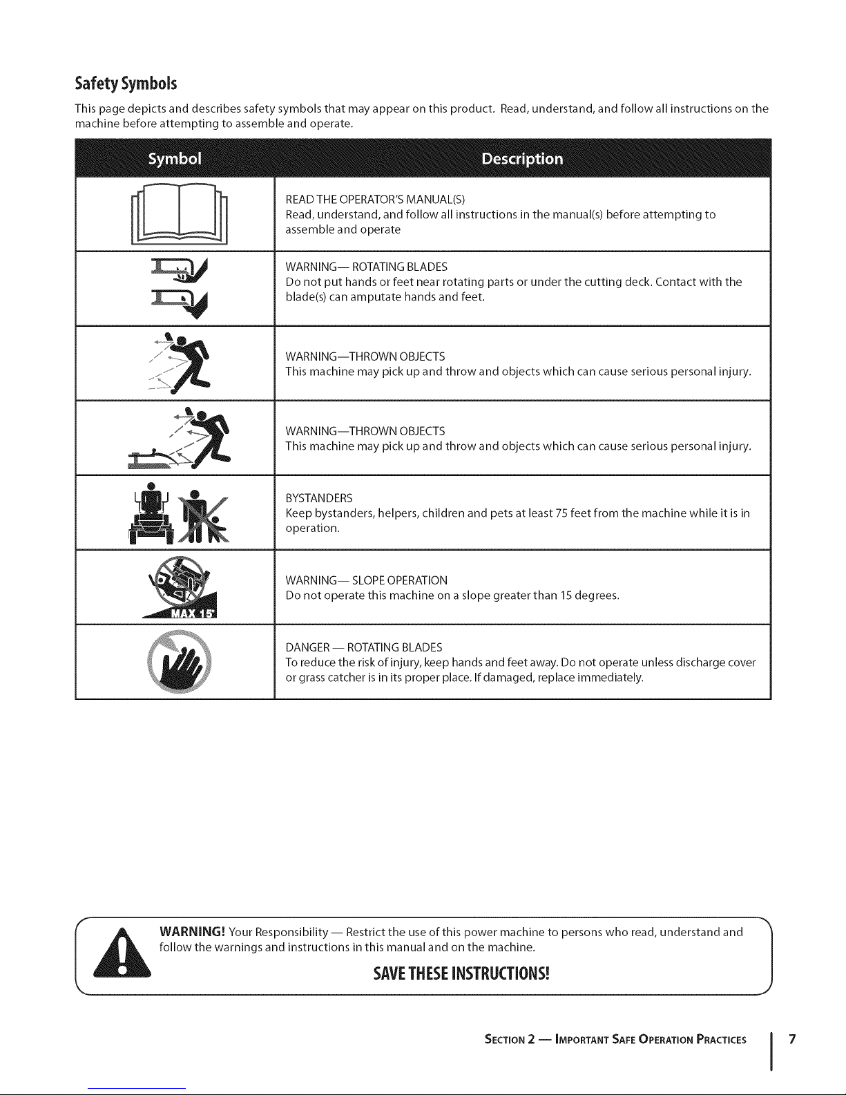
Safety Symbols
This page depicts and describes safety symbols that may appear on this product. Read, understand, and follow all instructions on the
machine before attempting to assemble and operate.
READ THE OPERATOR'S MANUAL(S)
Read, understand, and follow all instructions in the manual(s) before attempting to
assemble and operate
M
®
!!l"
N
WARNING-- ROTATING BLADES
Do not put hands or feet near rotating parts or under the cutting deck. Contact with the
blade(s) can amputate hands and feet.
WARNING--THROWN OBJECTS
This machine may pick up and throw and objects which can cause serious personal injury.
WARNING--THROWN OBJECTS
This machine may pick up and throw and objects which can cause serious personal injury.
BYSTANDERS
Keep bystanders, helpers, children and pets at least 75 feet from the machine while it is in
operation.
WARNING-- SLOPE OPERATION
Do not operate this machine on a slope greater than 15 degrees.
DANGER -- ROTATING BLADES
To reduce the risk of injury, keep hands and feet away. Do not operate unless discharge cover
or grass catcher is in its proper place. If damaged, replace immediately.
WARNING! Your Responsibility-- Restrict the use of this power machine to persons who read, understand and
follow the warnings and instructions in this manual and on the machine.
SAVETHESEINSTRUCTIONS!
SECTION 2 -- IMPORTANT SAFE OPERATION PRACTICES 7
Page 8
co
R
-4
6
Z
I
o
6
Z
-4
!
|
|
|
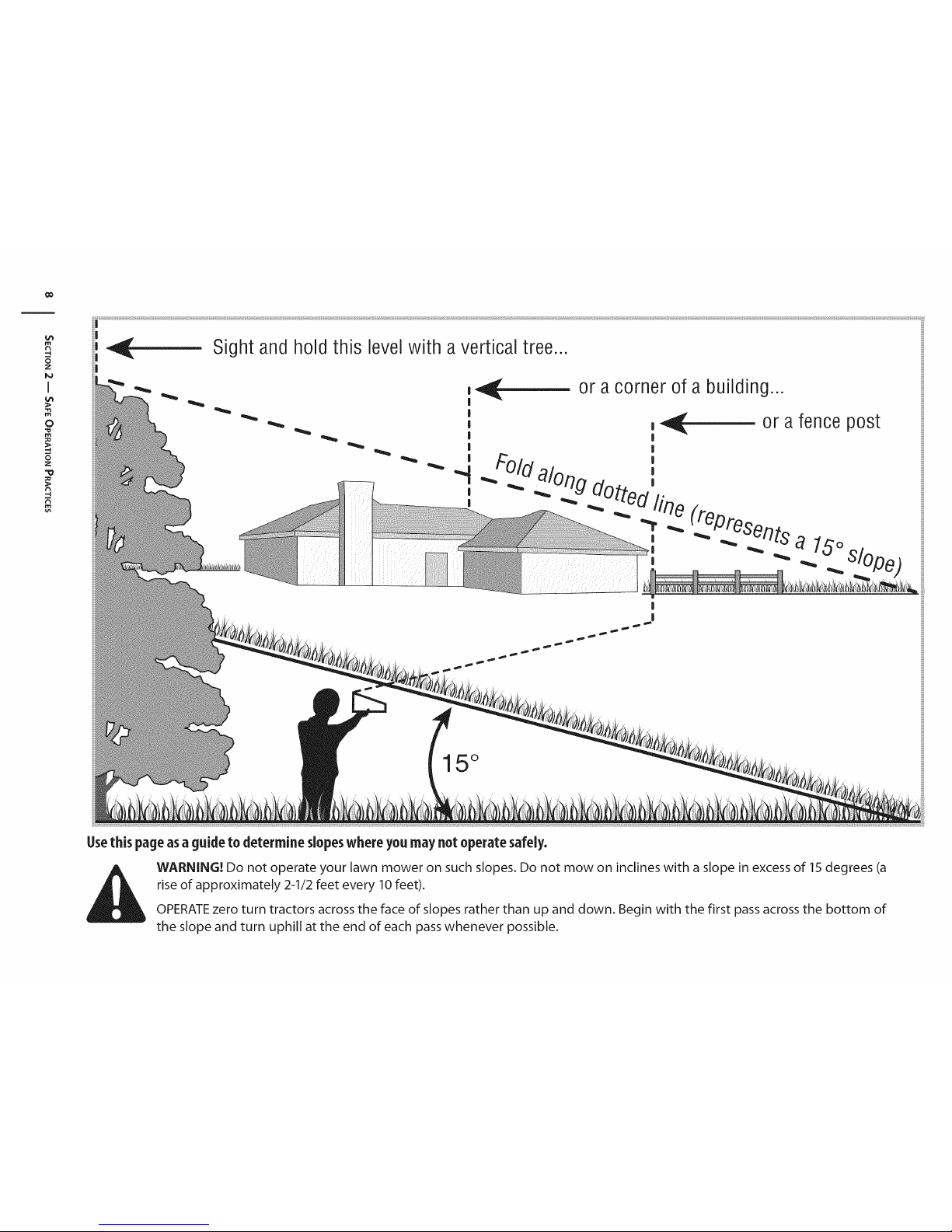
or a corner of a building...
|
15°
Use this page as a guide to determine slopes where you may not operate safely.
WARNING! Do not operate your lawn mower on such slopes. Do not mow on inclines with a slope in excess of 15 degrees (a
rise of approximately 2-1/2 feet every 10 feet).
OPERATE zero turn tractors across the face of slopes rather than up and down. Begin with the first pass across the bottom of
the slope and turn uphill at the end of each pass whenever possible.
Page 9
Assembly&Set-Up
Contents of Crate
3
One RZT Tractor
One RZT Tractor Operator's
Manual
NOTE:This Operator's Manual covers several models. Tractor
features may vary by model. Not all features in this manual are
applicable to all tractor models and the tractor depicted may
differ from yours.
One Oil Drain Tube
One Engine Operator's Manual
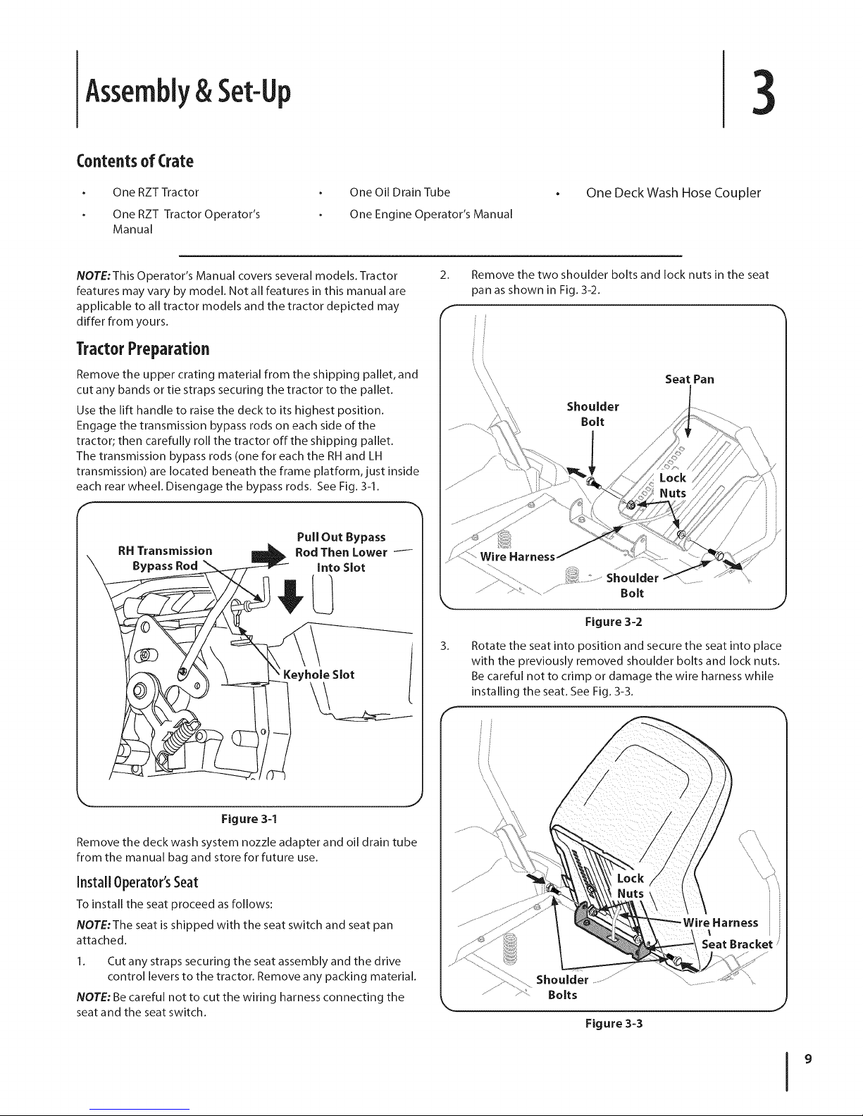
TractorPreparation
Remove the upper crating material from the shipping pallet, and
cut any bands or tie straps securing the tractor to the pallet.
Use the lift handle to raise the deck to its highest position.
Engage the transmission bypass rods on each side of the
tractor; then carefully roll the tractor off the shipping pallet.
The transmission bypass rods (one for each the RH and LH
transmission) are located beneath the frame platform, just inside
each rear wheel. Disengage the bypass rods. See Fig. 3-1.
RH Transmission
Bypass Rod
Pull Out Bypass
Rod Then Lower i
Into Slot
One Deck Wash Hose Coupler
2. Remove the two shoulder bolts and lock nuts in the seat
pan as shown in Fig. 3-2.
Seat Pan
Shoulder
Bolt
Bolt
Figure 3-2
3.
Rotate the seat into position and secure the seat into place
with the previously removed shoulder bolts and lock nuts.
Be careful not to crimp or damage the wire harness while
installing the seat. See Fig. 3-3.
J
Figure 3-1
Remove the deck wash system nozzle adapter and oil drain tube
from the manual bag and store for future use.
Install Operator'sSeat
To install the seat proceed as follows:
NOTE:The seat is shipped with the seat switch and seat pan
attached.
1. Cut any straps securing the seat assembly and the drive
control levers to the tractor. Remove any packing material.
NOTE: Be careful not to cut the wiring harness connecting the
seat and the seat switch.
J
Harness
Seat Bracket _
Shoulder
\
Bolts
J
Figure 3-3
Page 10
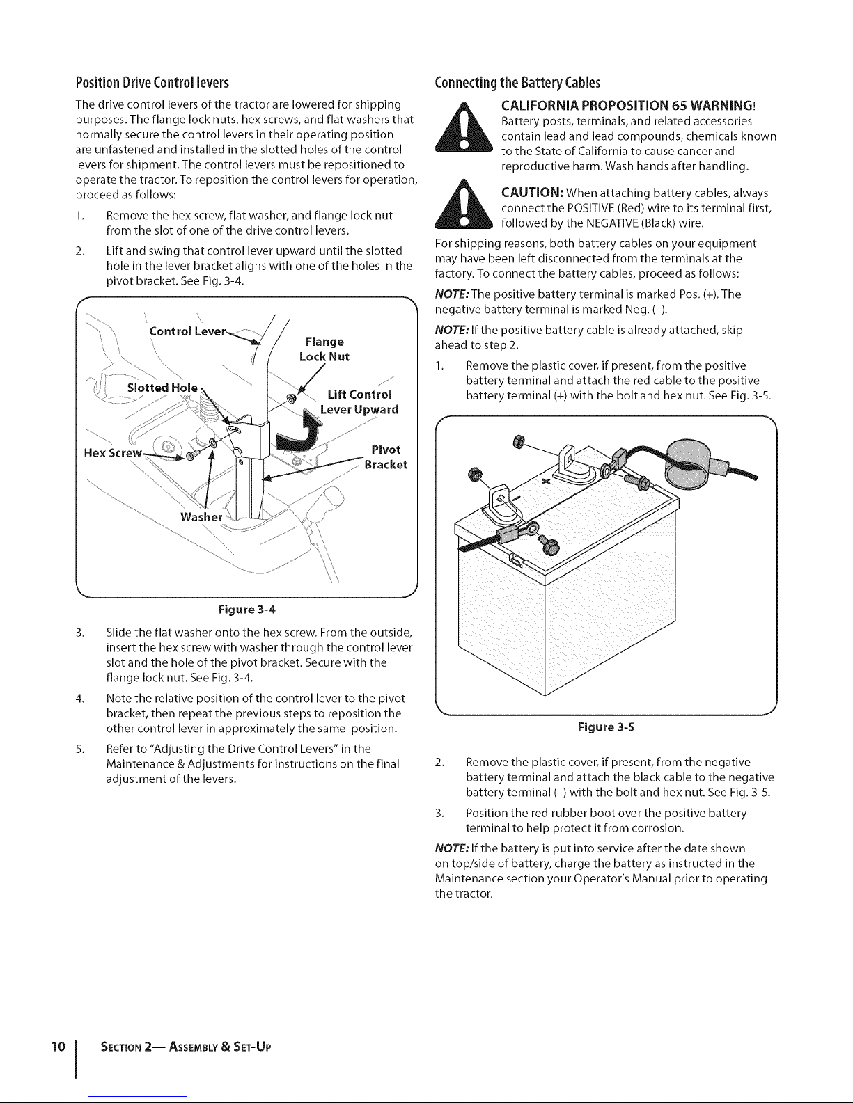
Position DriveControllevers
The drive control levers of the tractor are lowered for shipping
purposes. The flange lock nuts, hex screws, and flat washers that
normally secure the control levers in their operating position
are unfastened and installed in the slotted holes of the control
levers for shipment. The control levers must be repositioned to
operate the tractor. To reposition the control levers for operation,
proceed as follows:
1. Remove the hex screw, flat washer, and flange lock nut
from the slot of one of the drive control levers.
2.
Lift and swing that control lever upward until the slotted
hole in the lever bracket aligns with one of the holes in the
pivot bracket. See Fig. 3-4.
Lift Control
Lever Upwa rd
_s f_
Connectingthe Battery Cables
Battery posts, terminals, and related accessories
CALIFORNIA PROPOSITION 65 WARNING!
contain lead and lead compounds, chemicals known
to the State of California to cause cancer and
reproductive harm. Wash hands after handling.
connect the POSITIVE (Red) wire to its terminal first,
CAUTION: When attaching battery cables, always
followed by the NEGATIVE (Black) wire.
For shipping reasons, both battery cables on your equipment
may have been left disconnected from the terminals at the
factory. To connect the battery cables, proceed as follows:
NOTE:The positive battery terminal is marked Pos. (+). The
negative battery terminal is marked Neg. (-).
NOTE: If the positive battery cable is already attached, skip
ahead to step 2.
1. Remove the plastic cover, if present, from the positive
battery terminal and attach the red cable to the positive
battery terminal (+) with the bolt and hex nut. See Fig. 3-5.
F
Hex Screw.
Figure 3-4
3.
Slide the flat washer onto the hex screw. From the outside,
insert the hex screw with washer through the control lever
slot and the hole of the pivot bracket. Secure with the
flange lock nut. See Fig. 3-4.
4.
Note the relative position of the control lever to the pivot
bracket, then repeat the previous steps to reposition the
other control lever in approximately the same position.
5.
Refer to "Adjusting the Drive Control Levers" in the
Maintenance & Adjustments for instructions on the final
adjustment of the levers.
Pivot
Figure 3-5
2. Remove the plastic cover, if present, from the negative
battery terminal and attach the black cable to the negative
battery terminal (-) with the bolt and hex nut. See Fig. 3-5.
3. Position the red rubber boot over the positive battery
terminal to help protect it from corrosion.
NOTE: If the battery is put into service after the date shown
on top/side of battery, charge the battery as instructed in the
Maintenance section your Operator's Manual prior to operating
the tractor.
SECTION 2-- ASSEMBLY& SET-UP
Page 11
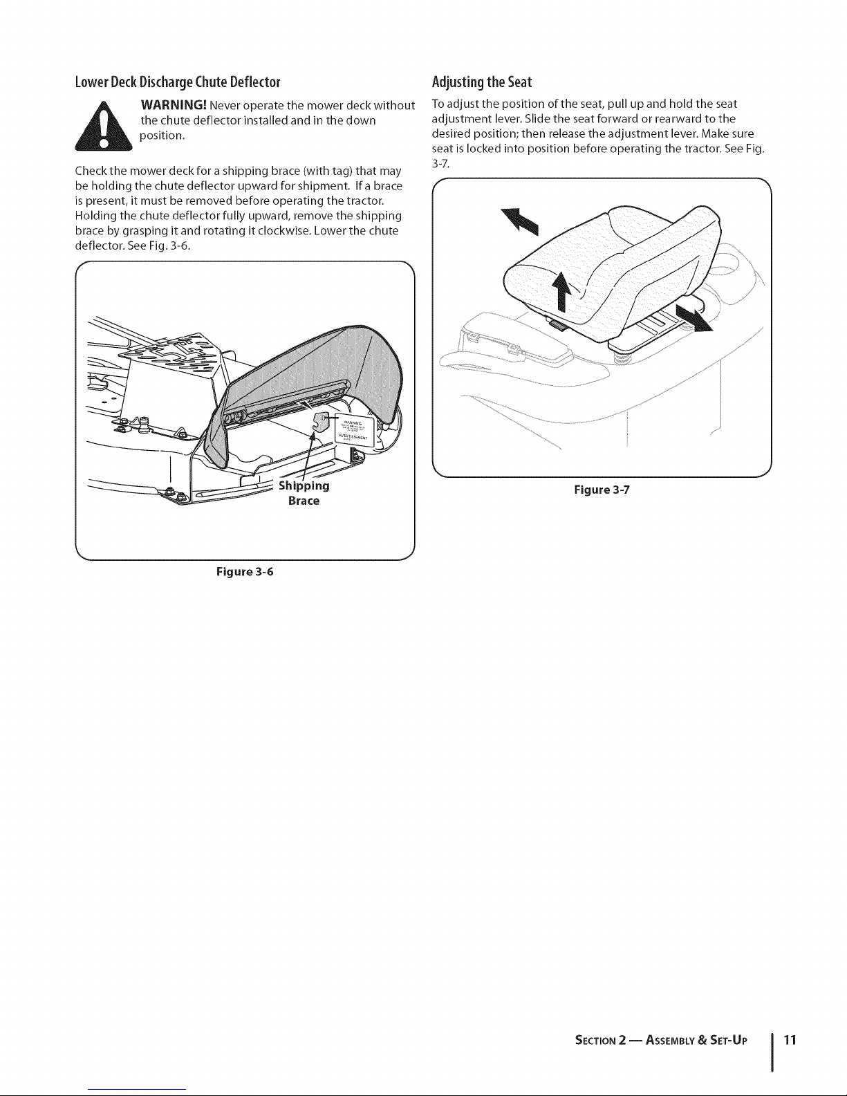
LowerDeckDischargeChuteDeflector
the chute deflector installed and in the down
_[_ ARNING! Never operate the mower deck without
Check the mower deck for a shipping brace (with tag) that may
be holding the chute deflector upward for shipment. Ifa brace
is present, it must be removed before operating the tractor.
Holding the chute deflector fully upward, remove the shipping
brace by grasping it and rotating it clockwise. Lower the chute
deflector. See Fig.3-6.
position.
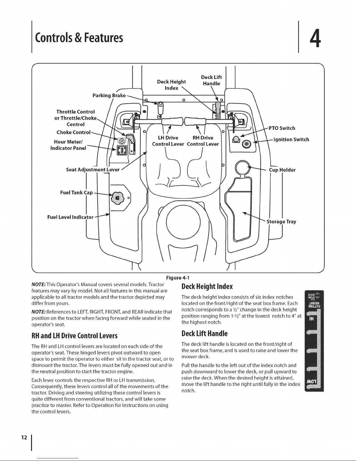
Adjusting the Seat
Toadjust the position of the seat, pull up and hold the seat
adjustment lever.Slide the seatforward or rearward to the
desired position; then release the adjustment lever. Make sure
seat is locked into position before operating the tractor. SeeFig.
3-7.
f
Figure 3-6
Figure 3-7
SECTION 2 -- ASSEMBLY& SET-UP 11
Page 12
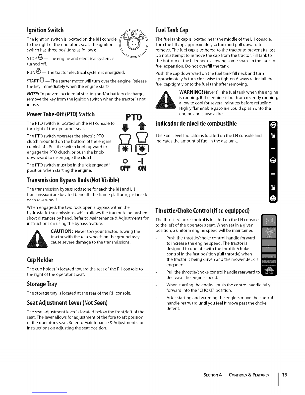
Controls& Features
F
4
Throttle Control
or Throttle/Choke
Control
Choke
Hour Meter/
indicator Panel
Seat Adjustment Lever
Fuel Tank Cap
I
I
Parking
Deck Height
index
LHDrive RH Drive
Control Lever Control Lever
Deck Lift
Handle
nition Switch
Cup Holder
Storage Tray
Figure 4=1
NOTE:This Operator's Manual covers several models. Tractor
features may vary by model. Not all features in this manual are
applicable to all tractor models and the tractor depicted may
differ from yours.
NOTE: References to LEFT, RIGHT, FRONT, and REAR indicate that
position on the tractor when facing forward while seated in the
operator's seat.
RHand[HDriveControl Levers
The RH and LH control levers are located on each side of the
operator's seat. These hinged levers pivot outward to open
space to permit the operator to either sit in the tractor seat, or to
dismount the tractor. The levers must be fully opened out and in
the neutral position to start the tractor engine.
Each lever controls the respective RH or LH transmission.
Consequently, these levers control all of the movements of the
tractor. Driving and steering utilizing these control levers is
quite different from conventional tractors, and will take some
practice to master. Refer to Operation for instructions on using
the control levers.
DeckHeightIndex
The deck height index consists of six index notches
located on the front/right of the seat box frame. Each
notch corresponds to a 1/S'change in the deck height
position ranging from 1-1/2"at the lowest notch to 4" at
the highest notch.
DeckLift Handle
The deck lift handle is located on the front/right of
the seat box frame, and is used to raise and lower the
mower deck.
Pull the handle to the left out of the index notch and
push downward to lower the deck, or pull upward to
raise the deck. When the desired height is attained,
move the lift handle to the right until fully in the index
notch.
Page 13
ignition Switch
The ignition switch is located on the RH console
to the right of the operator's seat. The ignition
switch has three positions as follows:
STOP _-- The engine and electrical system is
turned off.
RUN _-- The tractor electrical system is energized.
START _-- The starter motor will turn over the engine. Release
the key immediately when the engine starts
NOTE:To prevent accidental starting and/or battery discharge,
remove the key from the ignition switch when the tractor is not
in use.
PowerTake-Off(PTO)Switch
The PTO switch is located on the RH console to
the right of the operator's seat.
The PTO switch operates the electric PTO
clutch mounted on the bottom of the engine
crankshaft. Pull the switch knob upward to
engage the PTO clutch, or push the knob
downward to disengage the clutch.
The PTO switch must be in the "disengaged"
position when starting the engine.
PTO
• Q
NI
0 -I
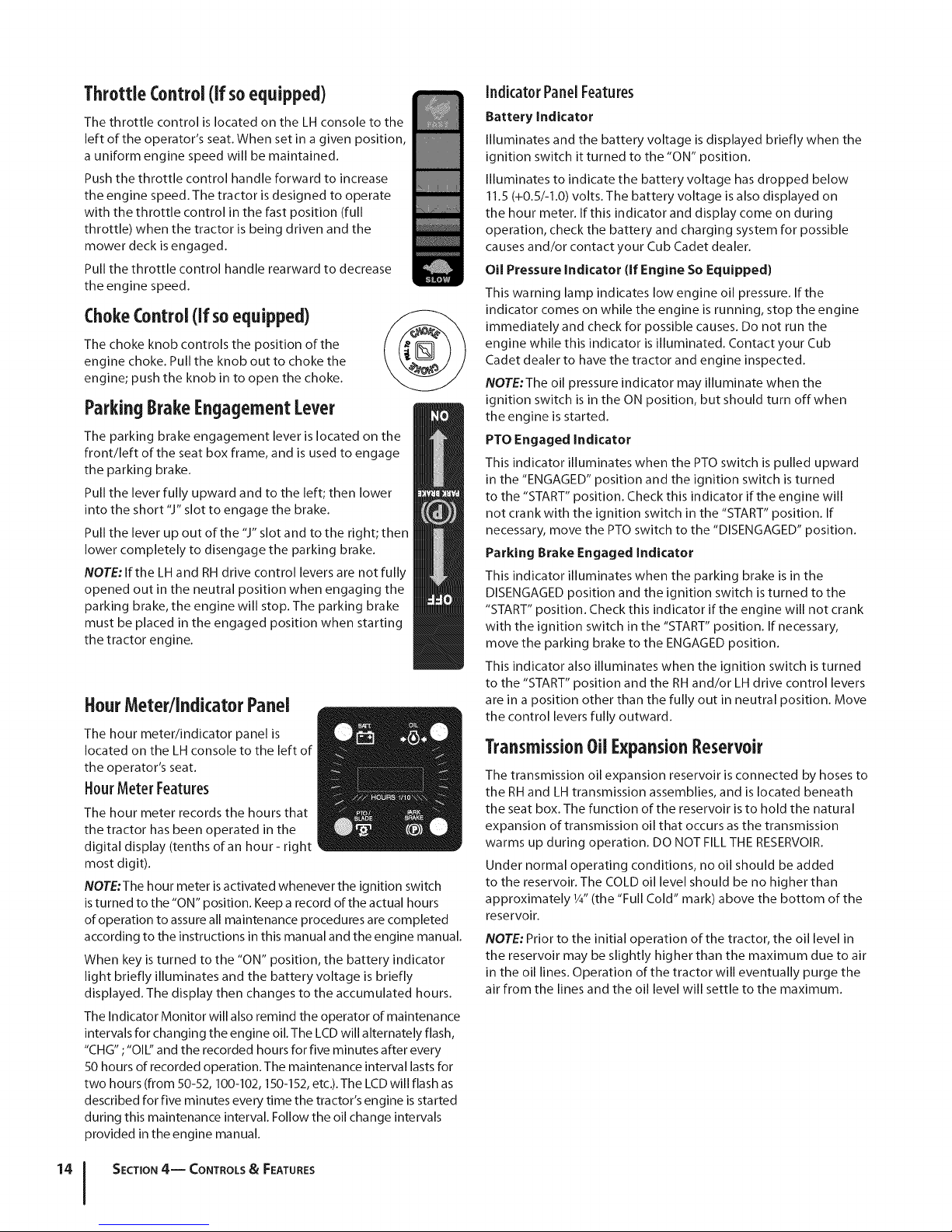
FuelTankCap
The fuel tank cap is located near the middle of the LH console.
Turn the fill cap approximately 1/4turn and pull upward to
remove. The fuel cap is tethered to the tractor to prevent its loss.
Do not attempt to remove the cap from the tractor. Fill tank to
the bottom of the filler neck, allowing some space in the tank for
fuel expansion. Do not overfill the tank.
Push the cap downward on the fuel tank fill neck and turn
approximately 1/4turn clockwise to tighten Always re-install the
fuel cap tightly onto the fuel tank after removing.
is running. If the engine is hot from recently running,
i_li WARNING! Never fill the fuel tank when the engine
allow to cool for several minutes before refueling.
Highly flammable gasoline could splash onto the
engine and cause a fire.
Indicador de nivei decombustible
The Fuel Level Indicator is located on the LH console and
indicates the amount of fuel in the gas tank.
Transmission BypassRods(Not Visible)
The transmission bypass rods (one for each the RH and LH
transmission) are located beneath the frame platform, just inside
each rear wheel.
When engaged, the two rods open a bypass within the
hydrostatic transmissions, which allows the tractor to be pushed
short distances by hand. Refer to Maintenance & Adjustments for
instructions on using the bypass feature.
tractor with the rear wheels on the ground may
CAUTION: Never tow your tractor. Towing the
causeseveredamage to the transmissions.
CupHolder
The cup holder is located toward the rear of the RH console to
the right of the operator's seat.
StorageTray
The storage tray is located at the rear of the RH console.
SeatAdjustmentLever(NotSeen)
The seat adjustment lever is located below the front/left of the
seat. The lever aIlows for adjustment of the fore to aft position
of the operator's seat. Refer to Maintenance & Adjustments for
instructions on adjusting the seat position.
Throttle/ChokeControl (if soequipped)
The throttle/choke control is located on the LH console
to the left of the operator's seat. When set in a given
position, a uniform engine speed will be maintained.
Push the throttle/choke control handle forward
to increase the engine speed. The tractor is
designed to operate with the throttle/choke
control in the fast position (full throttle) when
the tractor is being driven and the mower deck is
engaged.
Pull the throttle/choke control handle rearward to
decrease the engine speed.
When starting the engine, push the control handle fully
forward into the "CHOKE" position.
After starting and warming the engine, move the control
handle rearward until you feel it move past the choke
detent.
SECTION 4 -- CONTROLS & FEATURES 13
Page 14
ThrottleControl (if soequipped)
The throttle control is located on the LH console to the
left of the operator's seat. When set in a given position,
a uniform engine speed will be maintained.
Push the throttle control handle forward to increase
the engine speed. The tractor is designed to operate
with the throttle control in the fast position (full
throttle) when the tractor is being driven and the
mower deck is engaged.
Pull the throttle control handle rearward to decrease
the engine speed.
ChokeControl(if soequipped)
The choke knob controls the position of the
engine choke. Pull the knob out to choke the
engine; push the knob in to open the choke.
ParkingBrakeEngagementLever
The parking brake engagement lever is located on the
front/left of the seat box frame, and is used to engage
the parking brake.
Pull the lever fully upward and to the left; then lower
into the short "J" slot to engage the brake.
Pull the lever up out of the "J" slot and to the right; then
lower completely to disengage the parking brake.
NOTE: If the LH and RH drive control levers are not fully
opened out in the neutral position when engaging the
parking brake, the engine will stop. The parking brake
must be placed in the engaged position when starting
the tractor engine.
HourMeter/IndicatorPanel
The hour meter/indicator panel is
located on the LH console to the left of
the operator's seat.
HourMeter Features
The hour meter records the hours that
the tractor has been operated in the
digital display (tenths of an hour- right
most digit).
NOTE:The hour meter is activated whenever the ignition switch
is turned to the "ON" position. Keep a record of the actual hours
of operation to assure all maintenance procedures are completed
according to the instructions in this manual and the engine manual.
When key is turned to the "ON" position, the battery indicator
light briefly illuminates and the battery voltage is briefly
displayed. The display then changes to the accumulated hours.
The Indicator Monitor will also remind the operator of maintenance
intervals for changing the engine oil. The LCD will alternately flash,
"CHG" ;"Oli:' and the recorded hours for five minutes after every
50 hours of recorded operation. The maintenance interval lasts for
two hours (from 50-52, 100-102, 150-152, etc.). The LCD will flash as
described for five minutes every time the tractor's engine is started
during this maintenance interval. Follow the oil change intervals
provided in the engine manual.
Indicator PanelFeatures
Battery Indicator
Illuminates and the battery voltage is displayed briefly when the
ignition switch it turned to the "ON" position.
Illuminates to indicate the battery voltage has dropped below
11.5 (+0.5/-1.0) volts. The battery voltage is a Iso displayed on
the hour meter. If this indicator and display come on during
operation, check the battery and charging system for possible
causes and/or contact your Cub Cadet dealer.
Oil Pressure Indicator (If Engine So Equipped)
This warning lamp indicates low engine oil pressure. If the
indicator comes on while the engine is running, stop the engine
immediately and check for possible causes. Do not run the
engine while this indicator is illuminated. Contact your Cub
Cadet dealer to have the tractor and engine inspected.
NOTE:The oil pressure indicator may illuminate when the
ignition switch is in the ON position, but should turn offwhen
the engine is started.
PTO Engaged Indicator
This indicator illuminates when the PTO switch is pulled upward
in the "ENGAGED" position and the ignition switch is turned
to the "START" position. Check this indicator if the engine will
not crank with the ignition switch in the "START" position. If
necessary, move the PTO switch to the "DISENGAGED" position.
Parking Brake Engaged Indicator
This indicator illuminates when the parking brake is in the
DISENGAGED position and the ignition switch is turned to the
"START" position. Check this indicator if the engine will not crank
with the ignition switch in the "START" position. If necessary,
move the parking brake to the ENGAGED position.
This indicator also illuminates when the ignition switch is turned
to the "START" position and the RH and/or LH drive control levers
are in a position other than the fully out in neutral position. Move
the control levers fully outward.
TransmissionOilExpansionReservoir
The transmission oil expansion reservoir is connected by hoses to
the RH and LH transmission assemblies, and is located beneath
the seat box. The function of the reservoir is to hold the natural
expansion of transmission oil that occurs as the transmission
warms up during operation. DO NOT FILL THE RESERVOIR.
Under normal operating conditions, no oil should be added
to the reservoir. The COLD oil level should be no higher than
approximately 1/4"(the "Full Cold" mark) above the bottom of the
reservoir.
NOTE: Prior to the initial operation of the tractor, the oil level in
the reservoir may be slightly higher than the maximum due to air
in the oil lines. Operation of the tractor will eventually purge the
air from the lines and the oil level will settle to the maximum.
SECTION 4-- CONTROLS & FEATURES
Page 15
Operation
5
GeneralSafety
RECEIVE INSTRUCTION -- Entirely read this operator's
manual. Learn to operate this machine SAFELY.Do not risk
INJURY or DEATH. Allow only those who have become
competent in its usage to operate this tractor.
Before starting the engine or beginning operation, be familiar
with the controls. The operator should be in the operator's
seat. The PTO switch must be in the disengaged position,
the parking brake engaged, and the RH and LH drive control
levers moved fully outward in the neutral position.
Keep all shields in place. Keep away from moving parts.
NO RIDERS! Keep all people and pets a safe distance away.
Look behind and down to both sides of the tractor before
and while backing up.
DO NOT direct the mower discharge at people.
Avoid slopes where possible. Never operate on slopes
greater than 15°. Slopes with a greater incline present
dangerous operating conditions. Tractors can be rolled over.
Before leaving the operator's seat: Shut off the PTO, move
the RH and LH drive control levers fully outward in the
neutral position, engage the parking brake, shut offthe
engine and remove the ignition key. Wait for all movement
to stop before servicing or cleaning.
Operate the drive control levers smoothly and avoid
any sudden movements of the levers when starting and
stopping. Keep a firm grip on the control levers.
Be careful when operating near roadways. Stop the tractor
motion and wait for vehicles to pass before operating
along the road.
Do not operate the tractor with the mower deck removed.
Removal of the deck will change the balance of the tractor,
and could contribute to a tractor rollover.
Avoid operation on traction surfaces that are unstable; use
extreme caution if the surface is slippery.
Slow down before turning and come to a complete stop
before any zero turn maneuver.
Do not stop the tractor or park the tractor over
combustible materials such as dry grass, leaves, debris, etc.
Do not fill the fuel tank when the engine is running or
while the engine is hot. Allow the engine several minutes
to cool before refueling. Tighten the fuel cap securely.
BeforeOperatingYourTractor
Before you operate the tractor, study this manual carefully
to familiarize yourself with the operation of all the
instruments and controls. It has been prepared to help you
operate and maintain your tractor efficiently.
This engine is certified to operate only on clean, fresh,
unleaded regular gasoline. For best results, fill the fuel
tank with only clean, fresh, unleaded gasoline with a pump
sticker octane rating of 87 or higher.
Unleaded gasoline is recommended because it leaves less
combustion chamber deposits and reduces harmful exhaust
emissions. Leaded gasoline is not recommended and must
not be used where exhaust emissions are regulated.
NOTE: Purchase gasoline in small quantities. Do not use
gasoline left over from the previous season, to minimize
gum deposits in the fuel system.
Gasohol (up to 10% ethyl alcohol, 90% unleaded gasoline
by volume) isan approved fuel. Other gasoline/alcohol
blends are not approved.
Methyl Tertiary Butyl Ether (MTBE) and unleaded gasoline
blends (up to a maximum of 15% MTBE by volume) are
approved fuels. Other gasoline/ether blends are not approved.
Check the engine oil level.
Clean the air cleaner element if necessary.
Check the tire inflation pressures.
Adjust the seat for operator's maximum comfort, visibility
and for maintaining complete control of the tractor.
SafetyinterlockSystem
This tractor is equipped with a safety interlock system for the
protection of the operator. If the interlock system should ever
malfunction, do not operate the tractor. Contact your authorized
Cub Cadet Dealer.
The safety interlock system prevents the engine from
cranking or starting unless the RHand LH drive control
levers are moved fully outward in the neutral position, the
parking brake is engaged, and the PTO is disengaged.
To avoid sudden movement when disengaging the parking
brake, the safety interlock system will shut offthe engine
if the RH and/or LH drive control levers are moved to a
position other than the fully out in the neutral position
when the parking brake is engaged.
The safety interlock system will shut off the engine if the
operator leaves the seat before engaging the parking brake.
The safety interlock system will shut off the engine if the
operator leaves the seat with the PTO engaged, regardless
of whether the parking brake is engaged.
NOTE:The PTO switch must be moved to the "STOP"
position to restart the engine.
The safety interlock system will shut off the PTO and the
mower blades will stop if both drive control levers are
moved into the reverse position. The PTO will re-engage
when one or both of the levers are moved back to the
neutral or forward position.
15
Page 16
Startingthe Engine
WARNING! This tractor is equipped with a safety
interlock system designed for the protection of the
operator. Do not operate the tractor if any part of
the interlock system is malfunctioning. Periodically
check the functions of the interlock system for
proper operation.
WARNING! For personal safety, the operator must
be sitting in the tractor seat when starting the
engine.
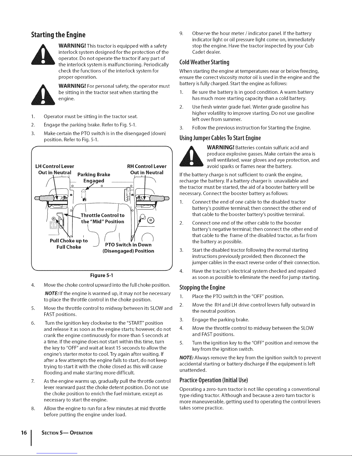
1. Operator must be sitting in the tractor seat.
2. Engage the parking brake. Refer to Fig. 5-1.
3. Make certain the PTO switch is in the disengaged (down)
position. Refer to Fig. 5-1.
LH Control Lever
Out in Neutral .....
j_______ l-arKing BraKe
_\ o_ Engaged
_ _----_L Throttle Control to
(_ . 11
Pull Choke up to 1 _ ,
FulIChoke -J PTO Switch
(Disengagedl Position
k_ j
Figure 5-1
4. Move the choke control upward into the full choke position.
NOTE: If the engine is warmed up, it may not be necessary
to place the throttle control in the choke position.
5. Move the throttle control to midway between its SLOW and
FAST positions.
6. Turn the ignition key clockwise to the "START" position
and release it as soon as the engine starts; however, do not
crank the engine continuously for more than 5 seconds at
a time. If the engine does not start within this time, turn
the key to "OFF" and wait at least 15 seconds to allow the
engine's starter motor to cool. Try again after waiting. If
after a few attempts the engine fails to start, do not keep
trying to start it with the choke closed as this will cause
flooding and make starting more difficult.
7. As the engine warms up, gradually pull the throttle control
lever rearward past the choke detent position. Do not use
the choke position to enrich the fuel mixture, except as
necessary to start the engine.
8. Allow the engine to run for a few minutes at mid throttle
before putting the engine under load.
RH Control Lever
Out in Neutral
in Down
9.
Observe the hour meter/indicator panel. If the battery
indicator light or oil pressure light come on, immediately
stop the engine. Have the tractor inspected by your Cub
Cadet dealer.
C01dWeatherStarting
When starting the engine at temperatures near or below freezing,
ensure the correct viscosity motor oil is used in the engine and the
battery is fully charged. Start the engine as follows:
I. Be sure the battery is in good condition. A warm battery
has much more starting capacity than a cold battery.
2. Use fresh winter grade fuel. Winter grade gasoline has
higher volatility to improve starting. Do not use gasoline
left over from summer.
3. Follow the previous instruction for Starting the Engine.
UsingJumperCablesToStart Engine
produce explosive gasses. Make certain the area is
WARNING! Batteries contain sulfuric acid and
well ventilated, wear gloves and eye protection, and
avoid sparks or flames near the battery.
If the battery charge is not sufficient to crank the engine,
recharge the battery. Ira battery charger is unavailable and
the tractor must be started, the aid of a booster battery will be
necessary. Connect the booster battery as follows:
I. Connect the end of one cable to the disabled tractor
battery's positive terminal; then connect the other end of
that cable to the booster battery's positive terminal.
2. Connect one end of the other cable to the booster
battery's negative terminal; then connect the other end of
that cable to the frame of the disabled tractor, as far from
the battery as possible.
3. Start the disabled tractor following the normal starting
instructions previously provided; then disconnect the
jumper cables in the exact reverse order of their connection.
4. Have the tractor's electrical system checked and repaired
as soon as possible to eliminate the need for jump starting.
Stoppingthe Engine
I. Place the PTO switch in the "OFF" position.
2. Move the RH and LH drive control levers fully outward in
the neutral position.
3. Engage the parking brake.
4. Move the throttle control to midway between the SLOW
and FAST positions.
5. Turn the ignition key to the "OFF" position and remove the
key from the ignition switch.
NOTE; Always remove the key from the ignition switch to prevent
accidental starting or battery discharge if the equipment is left
unattended.
PracticeOperation(Initial Use)
Operating a zero-turn tractor isnot like operating a conventional
type riding tractor. Although and because a zero turn tractor is
more maneuverable, getting used to operating the control levers
takes some practice.
SECTION S-- OPERATION
Page 17
It is strongly recommended that you locate a reasonably large,
level and open "practice area" where there are no obstructions,
pedestrians, or animals. You should practice operating the
tractor for a minimum of 30 minutes.
Carefully move (or have moved) the tractor to the practice area.
When performing the practice session, the PTO should not be
engaged. While practicing, operate the tractor at approximately
1/2-3Athrottle and at less than full speed in both forward and
reverse.
Carefully practice maneuvering the tractor using the instructions
in the following section "Driving the Tractor." Practice until you
are confident that you can safely operate the tractor.
Drivin9 the Tractor
WARNING! Avoid sudden starts, excessive speed
and sudden stops.
1. Adjust the operator's seat to the most comfortable
position that allows you to operate the controls. See seat
adjustment in the Assembly & Set-Up section.
2. Release the parking brake.
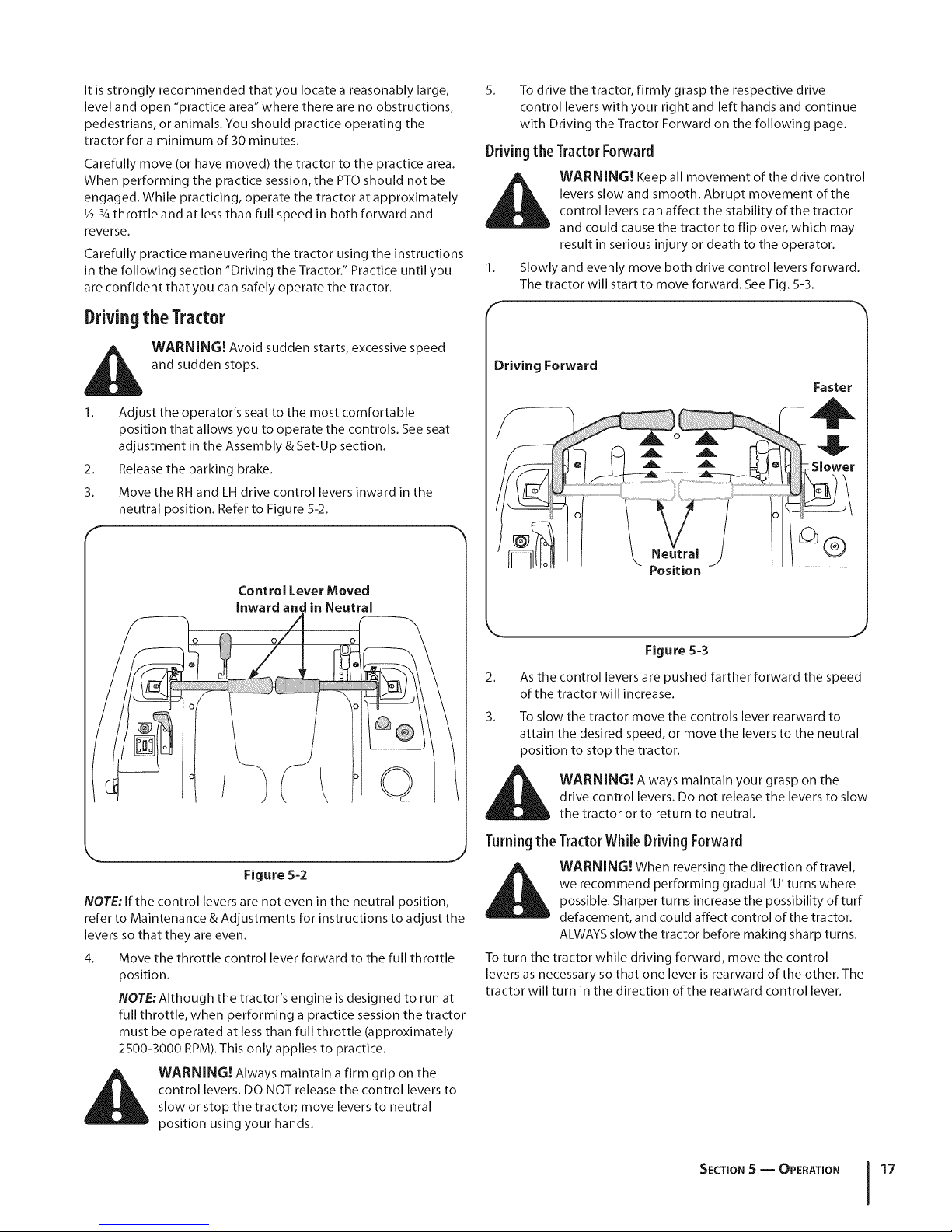
3. Move the RH and LH drive control levers inward in the
neutral position. Refer to Figure 5-2.
5.
To drive the tractor, firmly grasp the respective drive
control levers with your right and left hands and continue
with Driving the Tractor Forward on the following page.
Drivingthe TractorForward
levers slow and smooth. Abrupt movement of the
_ ARNING! Keep all movement of the drive control
control levers can affect the stability of the tractor
and could cause the tractor to flip over, which may
result in serious injury or death to the operator.
Slowly and evenly move both drive control levers forward.
The tractor will start to move forward. See Fig. 5-3.
F
Driving Forward
Faster
Control Lever Moved
Inward and in Neutral
/ Q
Figure 5-2
NOTE: If the control levers are not even in the neutral position,
refer to Maintenance & Adjustments for instructions to adjust the
levers so that they are even.
4. Move the throttle control lever forward to the full throttle
position.
NOTE:Although the tractor's engine is designed to run at
full throttle, when performing a practice session the tractor
must be operated at less than full throttle (approximately
2500-3000 RPM). This only applies to practice.
_] o Position
Figure 5-3
2. As the control levers are pushed farther forward the speed
of the tractor will increase.
3. To slow the tractor move the controls lever rearward to
attain the desired speed, or move the levers to the neutral
position to stop the tractor.
WARNING! Always maintain your grasp on the
drive control levers. Do not release the levers to slow
the tractor or to return to neutral.
Turningthe TractorWhile DrivingForward
WARNING! When reversing the direction of travel,
we recommend performing gradual 'U' turns where
possible. Sharper turns increase the possibility of turf
defacement, and could affect control of the tractor.
ALWAYS slow the tractor before making sharp turns.
To turn the tractor while driving forward, move the control
levers as necessary so that one lever is rearward of the other. The
tractor will turn in the direction of the rearward control lever.
control levers. DO NOT release the control levers to
_ WARNING! Always maintain a firm grip on the
slow or stop the tractor; move levers to neutral
position using your hands.
SECTION S -- OPERATION 17
Page 18
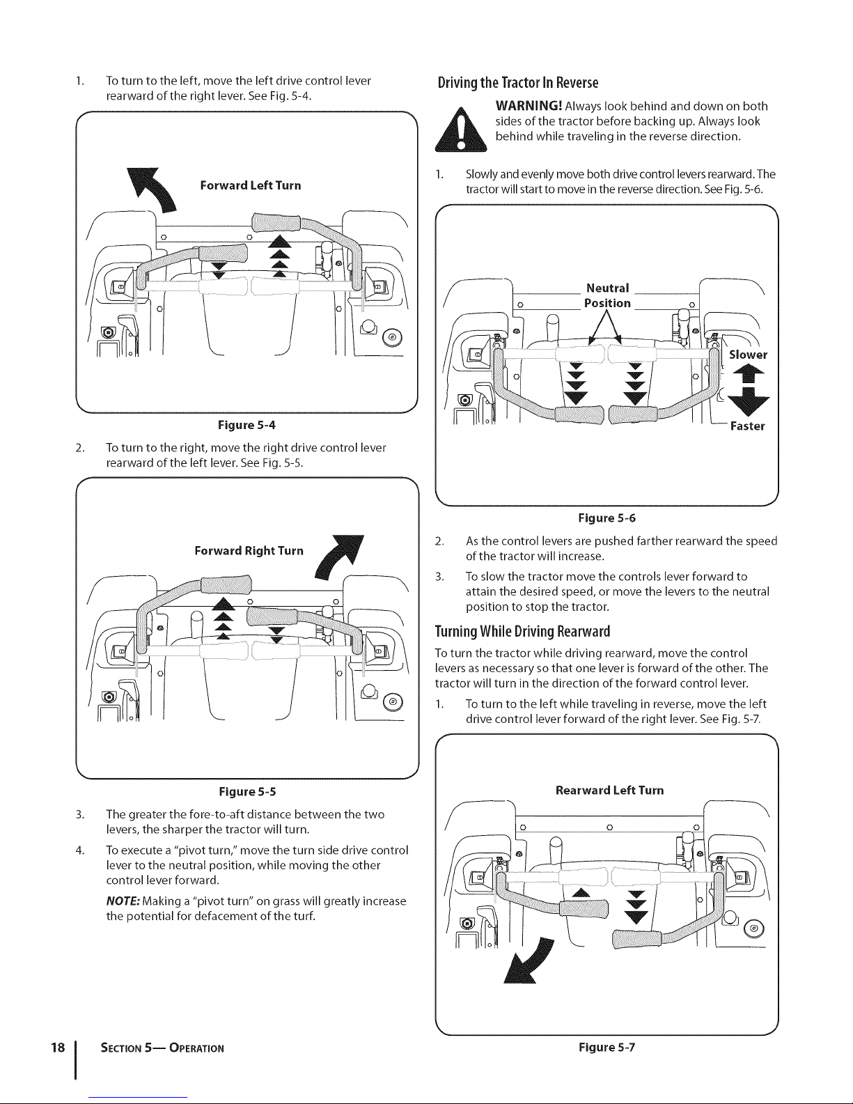
1. To turn to the left, move the left drive control lever
rearward of the right lever. See Fig. 5-4.
Forward Left Turn
Figure 5-4
2. To turn to the right, move the right drive control lever
rearward of the left lever. See Fig. 5-5.
Drivingthe Tract0rIn Reverse
WARNING! Always look behind and down on both
behind while traveling in the reverse direction.
sides of the tractor before backing up. Always look
1. Slowly and evenly move both drive control levers rearward. The
tractor will start to move in the reverse direction. See Fig. 5-6.
F
/f--h .eu,ra,
__//----- tlll_ Position o l
t li<_f If k........ ; ..... f 11 Slower
Hot \'_ "_l iol'/ I_-
Forward Right Turn
........] 1°
Figure 5-5
3. The greater the fore-to-aft distance between the two
levers, the sharper the tractor will turn.
4. To execute a "pivot turn," move the turn side drive control
lever to the neutral position, while moving the other
control lever forward.
NOTE: Making a "pivot turn" on grass will greatly increase
the potential for defacement of the turf.
Figure 5-5
2.
As the control levers are pushed farther rearward the speed
of the tractor will increase.
3. To slow the tractor move the controls lever forward to
attain the desired speed, or move the levers to the neutral
position to stop the tractor.
TurningWhile DrivingRearward
To turn the tractor while driving rearward, move the control
levers as necessary so that one lever is forward of the other. The
tractor will turn in the direction of the forward control lever.
1. To turn to the left while traveling in reverse, move the left
drive control lever forward of the right lever. See Fig. 5-7.
F
Rea rwa rd Left Turn
o o
SECTION 5-- OPERATION
\
Figure 5-7
Page 19
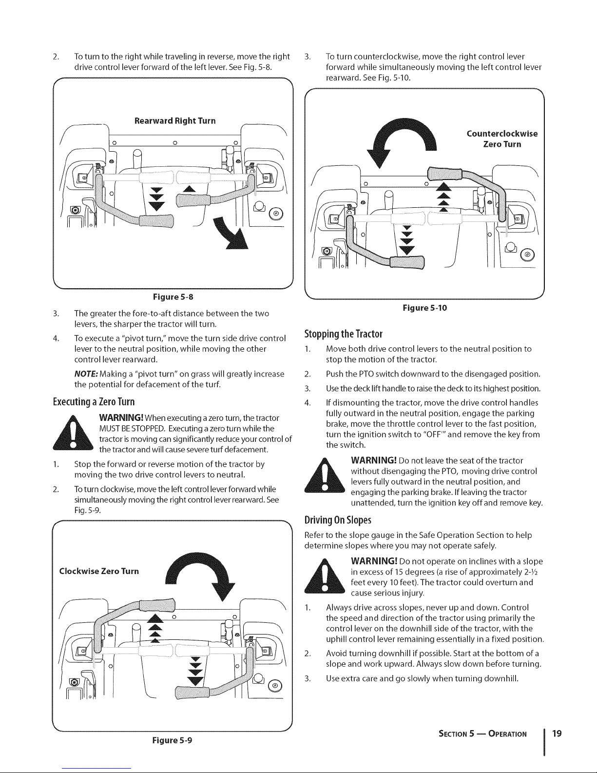
2. To turn to the right while traveling in reverse, move the right
drive control lever forward of the left lever. See Fig. 5-8.
Rearward Right Turn
k. _ j
Figure 5-8
3. The greater the fore-to-aft distance between the two
levers, the sharper the tractor will turn.
4. To execute a "pivot turn," move the turn side drive control
lever to the neutral position, while moving the other
control lever rearward.
NOTE: Making a "pivot turn" on grass will greatly increase
the potential for defacement of the turf.
Executinga Zer0Turn
MUST BESTOPPED. Executing a zero turn while the
_ ARNING! When executing azero turn, the tractor
1. Stop the forward or reverse motion of the tractor by
2. To turn clockwise, move the left control lever forward while
tractor is moving can significantly reduce your control of
the tractor and will cause severe turf defacement.
moving the two drive control levers to neutral.
simultaneously moving the right control lever rearward. See
Fig. 5-9.
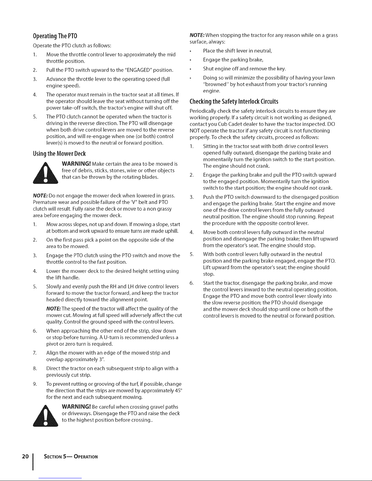
3.
To turn counterclockwise, move the right control lever
forward while simultaneously moving the left control lever
rearward. See Fig. 5-10.
f
Counterclockwise
Zero Turn
Figure 5=10
Stoppingthe Tractor
1. Move both drive control levers to the neutral position to
stop the motion of the tractor.
2. Push the PTO switch downward to the disengaged position.
3. Use the deck lift handle to raise the deck to its highest position.
4. If dismounting the tractor, move the drive control handles
fully outward in the neutral position, engage the parking
brake, move the throttle control lever to the fast position,
turn the ignition switch to "OFF'" and remove the key from
the switch.
without disengaging the PTO, moving drive control
WARNING! Do not leave the seat of the tractor
levers fully outward in the neutral position, and
engaging the parking brake. If leaving the tractor
unattended, turn the ignition key offand remove key.
DrivingOnSlopes
Refer to the slope gauge in the Safe Operation Section to help
determine slopes where you may not operate safely.
Clockwise Zero Turn
Figure 5-9
in excess of 15 degrees (a rise of approximately 2-_/2
WARNING! Do not operate on inclines with a slope
feet every 10 feet). The tractor could overturn and
cause serious injury.
1. Always drive across slopes, never up and down. Control
the speed and direction of the tractor using primarily the
control lever on the downhill side of the tractor, with the
uphill control lever remaining essentially in a fixed position.
2. Avoid turning downhill if possible. Start at the bottom of a
slope and work upward. Always slow down before turning.
3. Use extra care and go slowly when turning downhill.
J
SECTION S -- OPERATION 19
Page 20
OperatingThePTO
Operate the PTO clutch as follows:
1. Move the throttle control lever to approximately the mid
throttle position.
2. Pull the PTO switch upward to the "ENGAGED" position.
3. Advance the throttle lever to the operating speed (full
engine speed).
4. The operator must remain in the tractor seat at all times. If
the operator should leave the seat without turning off the
power take-off switch, the tractor's engine will shut off.
5. The PTO clutch cannot be operated when the tractor is
driving in the reverse direction. The PTO will disengage
when both drive control levers are moved to the reverse
position, and will re-engage when one (or both) control
lever(s) is moved to the neutral or forward position.
Usingthe Mower Deck
i_ WARNING! Make certain the area to be mowed is
NOTE: Do not engage the mower deck when lowered in grass.
Premature wear and possible failure of the 'V" belt and PTO
clutch will result. Fully raise the deck or move to a non grassy
area before engaging the mower deck.
1. Mow across slopes, not up and down. If mowing a slope, start
2. On the first pass pick a point on the opposite side of the
3. Engage the PTO clutch using the PTO switch and move the
4. Lower the mower deck to the desired height setting using
5. Slowly and evenly push the RH and LH drive control levers
6. When approaching the other end of the strip, slow down
7. Align the mower with an edge of the mowed strip and
8. Direct the tractor on each subsequent strip to align with a
9. To prevent rutting or grooving of the turf, if possible, change
free of debris, sticks, stones, wire or other objects
that can be thrown by the rotating blades.
at bottom and work upward to ensure turns are made uphill.
area to be mowed.
throttle control to the fast position.
the lift handle.
forward to move the tractor forward, and keep the tractor
headed directly toward the alignment point.
NOTE:The speed of the tractor will affect the quality of the
mower cut. Mowing at full speed will adversely affect the cut
quality. Control the ground speed with the control levers.
or stop before turning. A U-turn is recommended unless a
pivot or zero turn is required.
overlap approximately 3".
previously cut strip.
the direction that the strips are mowed by approximately 45°
for the next and each subsequent mowing.
NOTE: When stopping the tractor for any reason while on a grass
surface, always:
Place the shift lever in neutral,
Engage the parking brake,
Shut engine off and remove the key.
Doing so will minimize the possibility of having your lawn
"browned" by hot exhaust from your tractor's running
engine.
Checkingthe SafetyInterlock Circuits
Periodically check the safety interlock circuits to ensure they are
working properly. Ira safety circuit is not working as designed,
contact you Cub Cadet dealer to have the tractor inspected. DO
NOT operate the tractor if any safety circuit is not functioning
properly. To check the safety circuits, proceed asfollows:
1. Sitting in the tractor seat with both drive control levers
opened fully outward, disengage the parking brake and
momentarily turn the ignition switch to the start position.
The engine should not crank.
2. Engage the parking brake and pull the PTO switch upward
to the engaged position. Momentarily turn the ignition
switch to the start position; the engine should not crank.
3. Push the PTO switch downward to the disengaged position
and engage the parking brake. Start the engine and move
one of the drive control levers from the fully outward
neutral position. The engine should stop running. Repeat
the procedure with the opposite control lever.
4. Move both control levers fully outward in the neutral
position and disengage the parking brake; then lift upward
from the operator's seat. The engine should stop.
5. With both control levers fully outward in the neutral
position and the parking brake engaged, engage the PTO.
Lift upward from the operator's seat; the engine should
stop.
6. Start the tractor, disengage the parking brake, and move
the control levers inward to the neutral operating position.
Engage the PTO and move both control lever slowly into
the slow reverse position; the PTO should disengage
and the mower deck should stop until one or both of the
control levers is moved to the neutral or forward position.
i_ WARNING! Be careful when crossing gravel paths
or driveways. Disengage the PTO and raise the deck
to the highest position before crossing..
SECTION S-- OPERATION
Page 21
Maintenance&Adjustments
MaintenanceSchedule
6
Before
Eachuse
CheckEngineintakeScreen/Cover
CleanHood/DashLouvers _
CleanBattery Terminals _
LubeFrontPivot AxleandCasterAxles _
CleanEngineCoolingFins V/" V/"
LubeFrontDeckWheels V / V/
NOTE:This Operator's Manual covers several models. Tractor 2.
features may vary by model. Not all features in this manual are
applicable to all tractor models and the tractor depicted may
differ from yours. 3.
,/
Maintenance
WARNING! Before performing any maintenance or
repairs, disengage the PTO, move the drive control
levers fully outward in the neutral position, engage
the parking brake, stop the engine and remove the
key to prevent unintended starting.
Every
lOHours
f
Every
25 Hours
Move the tractor to an area within reach of the hose where the
dispersal of wet grass clippings is acceptable to you. Disengage
the PTO,engage the parking brake and stop the engine.
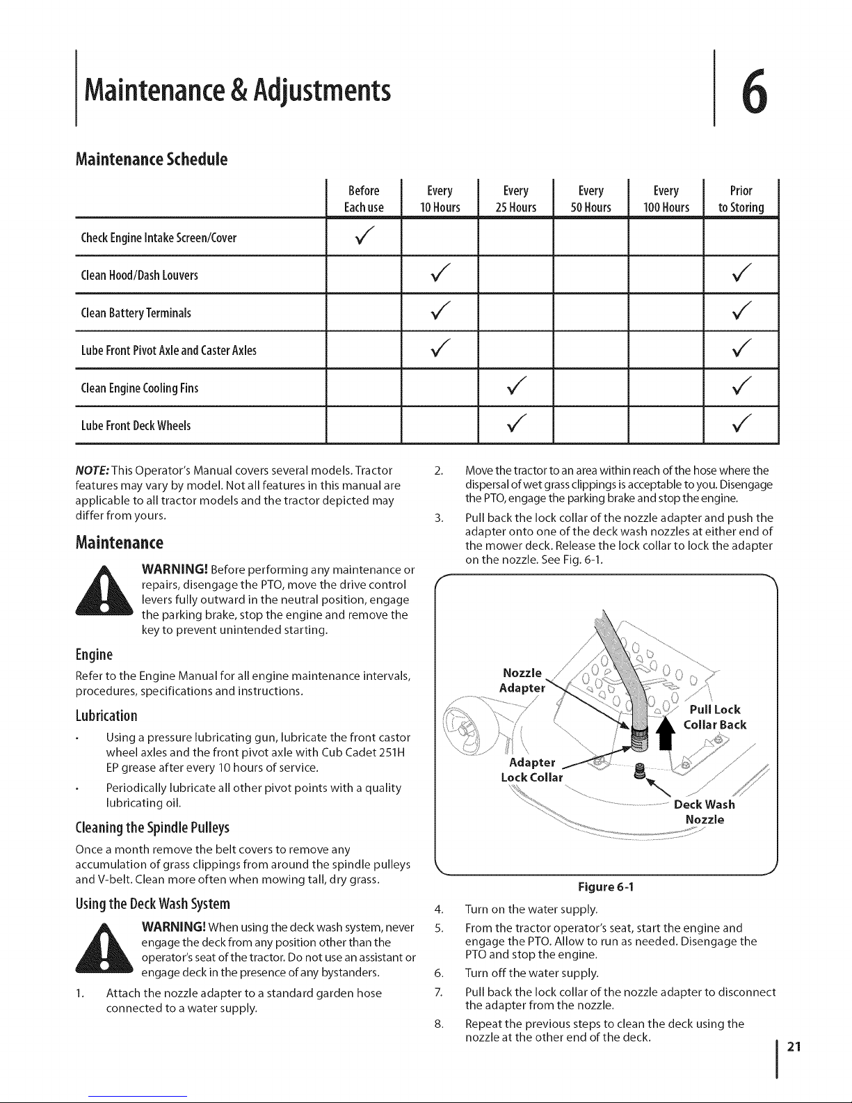
Pull back the lock collar of the nozzle adapter and push the
adapter onto one of the deck wash nozzles at either end of
the mower deck. Release the lock collar to lock the adapter
on the nozzle. See Fig. 6-1.
Every
50 Hours
Every
I00 Hours
toStoring
Prior
Engine
Refer to the Engine Manual for all engine maintenance intervals,
procedures, specifications and instructions.
Lubrication
Using a pressure lubricating gun, lubricate the front castor
wheel axles and the front pivot axle with Cub Cadet 251H
EP grease after every 10 hours of service.
Periodically lubricate all other pivot points with a quality
lubricating oil.
Cleaningthe SpindlePulleys
Once a month remove the belt covers to remove any
accumulation of grass clippings from around the spindle pulleys
and V-belt. Clean more often when mowing tall, dry grass.
Usingthe DeckWashSystem
WARNING! When using the deck wash system, never
engage the deck from any position other than the
operator's seat of the tractor. Do not use an assistant or
engage deck in the presence of any bystanders.
1. Attach the nozzle adapter to a standard garden hose
connected to a water supply.
Nozzle
Aria
Pull Lock
Collar Back
Adapter
L j
Figure 6=1
4. Turn on the water supply.
5. From the tractor operator's seat, start the engine and
engage the PTO. Allow to run as needed. Disengage the
PTO and stop the engine.
6. Turn off the water supply.
7. Pull back the lock collar of the nozzle adapter to disconnect
the adapter from the nozzle.
8. Repeat the previous steps to clean the deck using the
nozzle at the other end of the deck.
21
Page 22
TireMaintenance
Check the tire air pressure after every 50 hours of operation or
weekly. Keep the tires inflated to the recommended pressures.
Improper inflation will shorten the tire service life. See the tire side
wall for proper inflation pressures. Observe the following guidelines:
Do not inflate a tire above the maximum pressure shown
on the sidewall of the tire.
Do not reinflate a tire that has been run flat or seriously under
inflated. Have it inspected and serviced bya qualified tire
mechanic.
GeneralBattery Information
_lh WARNING!
, Should battery acid accidentally splatter into
the eyes or onto the skin, rinse the affected area
immediately with clean cold water. If there is any
further discomfort, seek prompt medical attention.
If acid spills on clothing, first dilute it with clean
water, then neutralize with a solution of ammonia/
water or baking soda/water.
NEVER connect (or disconnect) battery charger
clips to the battery while the charger is turned on, as
it can cause sparks.
Keep all sources of ignition (cigarettes, matches,
lighters) away from the battery. The gas generated
during charging can be combustible.
As a further precaution, only charge the battery
in a well ventilated area.
Always shield eyes and protect skin and clothing
when working near batteries.
Batteries contain sulfuric acid and may emit
explosive gases. Use extreme caution when handling
batteries. Keep batteries out of the reach of children.
4.
Recharge the battery before returning to service. Although
the tractor may start, the engine charging system may not
fully recharge the battery.
Usingthe TransmissionBypassRods
If for any reason the tractor will not drive or you wish to move the
tractor, the two hydrostatic transmissions are equipped with a bypass
rod that will allow you to manually move the tractor short distances.
bypass rod engaged. Serious transmission damage
WARNING! Do not tow the tractor, even with the
will result from doing so.
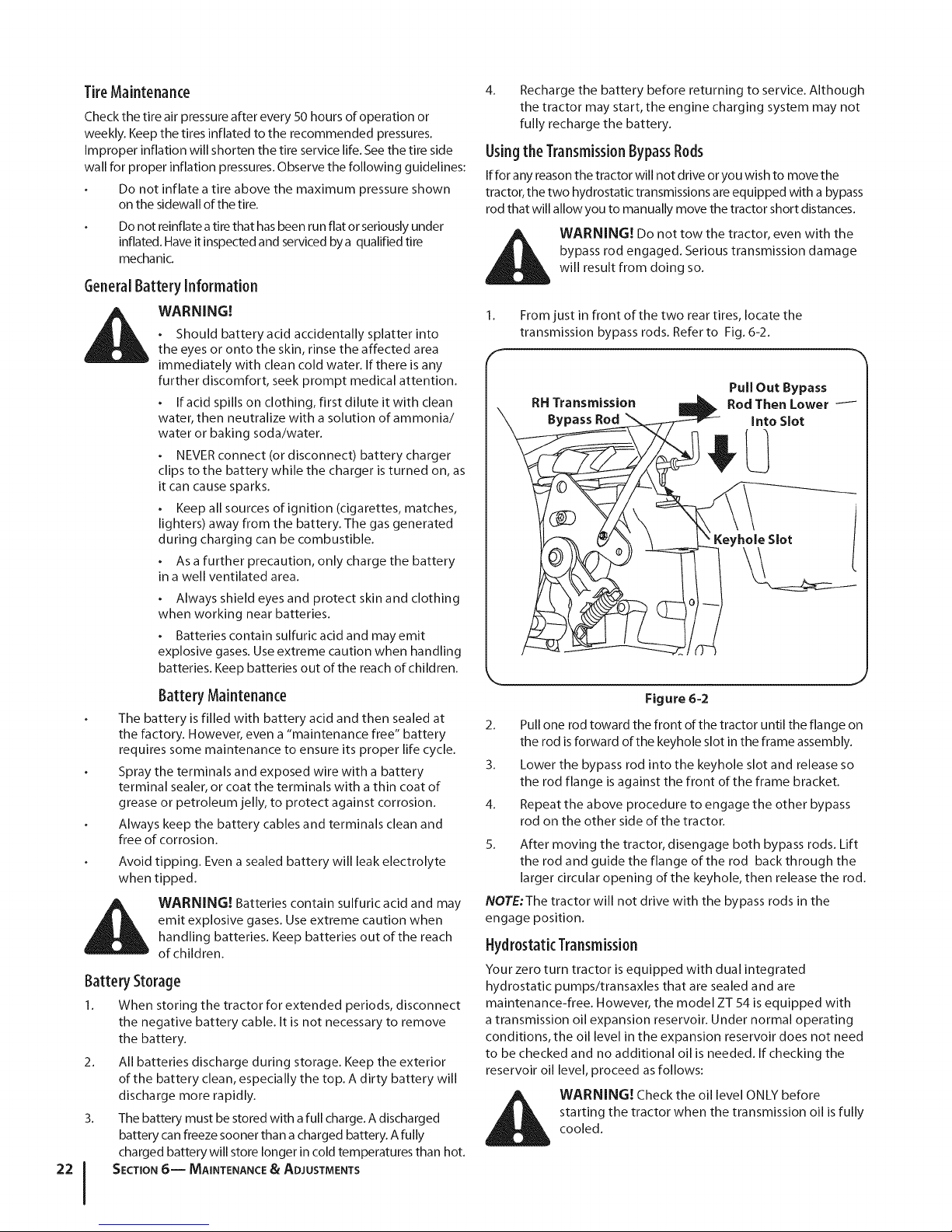
1. From just in front of the two rear tires, locate the
transmission bypass rods. Refer to Fig. 6-2.
RH Transmission
Bypass Rod
Pull Out Bypass
Rod Then Lower i
Into Slot
Keyhole Slot
Battery Maintenance
The battery is filled with battery acid and then sealed at
the factory. However, even a "maintenance free" battery
requires some maintenance to ensure its proper life cycle.
Spray the terminals and exposed wire with a battery
terminal sealer, or coat the terminals with a thin coat of
grease or petroleum jelly, to protect against corrosion.
Always keep the battery cables and terminals clean and
free of corrosion.
Avoid tipping. Even a sealed battery will leak electrolyte
when tipped.
WARNING! Batteries contain sulfuric acid and may
emit explosive gases. Use extreme caution when
handling batteries. Keep batteries out of the reach
of children.
Battery Storage
1. When storing the tractor for extended periods, disconnect
the negative battery cable. It is not necessary to remove
the battery.
2. All batteries discharge during storage. Keep the exterior
of the battery clean, especially the top. A dirty battery will
discharge more rapidly.
3. The battery must be stored with a full charge. A discharged
battery can freeze sooner than a charged battery. A fully
charged battery will store longer in cold temperatures than hot.
SECTION6-- MAINTENANCE& ADJUSTMENTS
Figure 6-2
2. Pull one rod toward the front of the tractor until the flange on
the rod is forward of the keyhole slot in the frame assembly.
3. Lower the bypass rod into the keyhole slot and release so
the rod flange is against the front of the frame bracket.
4. Repeat the above procedure to engage the other bypass
rod on the other side of the tractor.
5. After moving the tractor, disengage both bypass rods. Lift
the rod and guide the flange of the rod back through the
larger circular opening of the keyhole, then release the rod.
NOTE:The tractor will not drive with the bypass rods in the
engage position.
Hydrostatic Transmission
Your zero turn tractor is equipped with dual integrated
hydrostatic pumps/transaxles that are sealed and are
maintenance-flee. However, the model ZT 54 is equipped with
a transmission oil expansion reservoir. Under normal operating
conditions, the oil level in the expansion reservoir does not need
to be checked and no additional oil is needed. If checking the
reservoir oil level, proceed as follows:
_ WARNING! Check the oil level ONLY before
starting the tractor when the transmission oil is fully
cooled.
Page 23
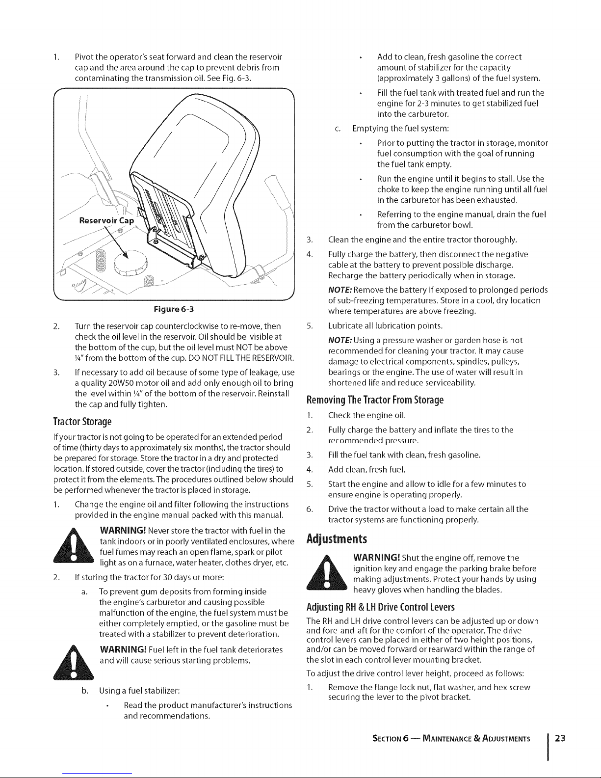
Pivottheoperator'sseatforwardandcleanthereservoir
capandtheareaaroundthecaptopreventdebrisfrom
contaminatingthetransmissionoil.SeeFig.6-3.
Figure 6-3
2. Turn the reservoir cap counterclockwise to re-move, then
check the oil level in the reservoir. Oil should be visible at
the bottom of the cup, but the oil level must NOT be above
1A"from the bottom of the cup. DO NOT FILL THE RESERVOIR.
3. If necessary to add oil because of some type of leakage, use
a quality 20W50 motor oil and add only enough oil to bring
the level within 1/4"of the bottom of the reservoir. Reinstall
the cap and fully tighten.
TractorStorage
If your tractor is not going to be operated for an extended period
of time (thirty days to approximately six months), the tractor should
be prepared for storage. Store the tractor in a dry and protected
location. If stored outside, cover the tractor (including the tires) to
protect it from the elements. The procedures outlined below should
be performed whenever the tractor is placed in storage.
1. Change the engine oil and filter following the instructions
provided in the engine manual packed with this manual.
WARNING! Never store the tractor with fuel in the
tank indoors or in poorly ventilated enclosures, where
fuel fumes may reach an open flame, spark or pilot
light as on a furnace, water heater, clothes dryer, etc.
If storing the tractor for 30 days or more:
a. To prevent gum deposits from forming inside
the engine's carburetor and causing possible
malfunction of the engine, the fuel system must be
either completely emptied, or the gasoline must be
treated with a stabilizer to prevent deterioration.
WARNING! Fuel left in the fuel tank deteriorates
and will cause serious starting problems.
b. Using a fuel stabilizer:
Read the product manufacturer's instructions
and recommendations.
Add to clean, fresh gasoline the correct
amount of stabilizer for the capacity
(approximately 3 gallons) of the fuel system.
Fill the fuel tank with treated fuel and run the
engine for 2-3 minutes to get stabilized fuel
into the carburetor.
C_
Emptying the fuel system:
Prior to putting the tractor in storage, monitor
fuel consumption with the goal of running
the fuel tank empty.
Run the engine until it begins to stall. Use the
choke to keep the engine running until all fuel
in the carburetor has been exhausted.
Referring to the engine manual, drain the fuel
from the carburetor bowl.
3. Clean the engine and the entire tractor thoroughly.
4. Fully charge the battery, then disconnect the negative
cable at the battery to prevent possible discharge.
Recharge the battery periodically when in storage.
NOTE: Remove the battery if exposed to prolonged periods
of sub-freezing temperatures. Store in a cool, dry location
where temperatures are above freezing.
5. Lubricate all lubrication points.
NOTE: Using a pressure washer or garden hose is not
recommended for cleaning your tractor. It may cause
damage to electrical components, spindles, pulleys,
bearings or the engine. The use of water will result in
shortened life and reduce serviceability.
RemovingTheTractorFromStorage
1. Check the engine oil.
2. Fully charge the battery and inflate the tires to the
recommended pressure.
3. Fill the fuel tank with clean, fresh gasoline.
4. Add clean, fresh fuel.
5. Start the engine and allow to idle for a few minutes to
ensure engine is operating properly.
6. Drive the tractor without a load to make certain all the
tractor systems are functioning properly.
Adjustments
ignition key and engage the parking brake before
_k ARNING! Shut the engine off, remove the
AdjustingRH& LHDriveControlLevers
The RH and LH drive control levers can be adjusted up or clown
and fore-and-aft for the comfort of the operator. The drive
control levers can be placed in either of two height positions,
and/or can be moved forward or rearward within the range of
the slot in each control lever mounting bracket.
To adjust the drive control lever height, proceed as follows:
making adjustments. Protect your hands by using
heavy gloves when handling the blades.
Remove the flange lock nut, flat washer, and hex screw
securing the lever to the pivot bracket.
SECTION 6 -- MAINTENANCE & ADJUSTMENTS 23
Page 24

2. While supporting the control lever to keep it from falling, 3.
remove the flange lock nut and shoulder screw from the
bottom of the control lever and pivot bracket. Refer to Fig.6-4.
3. Reposition the control lever to align with the other set of holes
in the pivot bracket and insert the shoulder screw removed 4.
earlier. Fasten with the flange lock nut and tighten until snug.
4. Insert the hex screw with washer through the control lever
slot and the pivot bracket. Thread the flange lock nut onto
the screw, but do not tighten now.
5. If you are going to adjust the control levers forward or rearward,
proceed to the next step. If not, fully tighten the flange lock nut.
To adjust the drive control levers forward/rearward, proceed asfollows:
1. If not already loose, loosen the flange lock nut and rotate
the control lever either forward or rearward to the desired
position. See Fig. 6-4.
Pivot Bracket
Measure the distance from the outside left blade tip to the
ground and the distance from the outside right blade tip to
the ground. The measurements should be equal. If they're
not, proceed to the next step.
Comparing the two measurements, determine whether the
left side of the deck must be raised or lowered.
5.
Loosen, but do not remove, the hex cap screw on the left
deck hanger bracket. See Fig. 6-5.
\\
Figure 6-4
NOTE: If the control lever is too tight to move, slightly
loosen the hex insert flange lock nut and shoulder screw at
the bottom of the control lever.
2. Tighten the flange lock nut to fix the control lever in the
adjusted position
3. Repeat the above procedure to adjust the other control
lever into the same position. Adjust so that both levers are
even with each other when in the neutral position.
Levelingthe Mower Deck
When correctly adjusted the mower deck should be level side to
side, and the front of the deck should be approximately 1/4"lower
than the rear of deck.
NOTE: Check the tractor's tire pressure before performing any deck
leveling adjustments. See tire side wall for proper inflation pressures.
Side to Side Leveling
If the cutting deck appears to be mowing unevenly, a side to side
adjustment can be performed. Adjust if necessary as follows:
1. With the tractor parked on a firm, level surface, place the deck
lift handle in the top notch (highest position) and rotate both
outer blades so that they are perpendicular to the tractor frame.
2. Lower the deck to the middle height position.
Figure 6=5
6. Levelthe deck by usinga wrench to turn theadjustment gear
(found immediately behind the hexcap screwjust loosened)
clockwise to raisethe left sideof the deck,or counterclockwise
to lower the left side ofthe deck. SeeFig.6-5.
7. The deck is properly leveled when left and right blade tip
measurements are equal.
8. Retighten the hex cap screw on the left deck hanger
bracket when proper adjustment is achieved.
Front to Back Leveling.
1. The front of the deck should be approximately 1/4"lower
than the rear of the deck. Adjust if necessary asfollows:
2. With the deck raised off of the ground, rotate the outer
blades so that they are parallel to the frame of the tractor.
3. If the side to side leveling was done correctly, measuring
just the right blade should be acceptable to attain the
correct back to front pitch of the deck.
4. Measure the distance from the front tip of the blade to the
ground and the distance from the rear tip to the ground.
The front distance should be approximately 1/4"lessthan
the rear.If it is not, proceed to the next step.
SECTION 6-- MAINTENANCE & ADJUSTMENTS
Page 25

5. From the front of the tractor, loosen the outer hex nuts on
the deck front hanger rod and turn them away from the
inner nuts. Refer to Fig. 6-6.
Adjusting the FrontGaugeWheelsand RearRollers
discharge opening of the cutting deck.
_ WARNING!: Keep hands and feet away from the
inner
Hex Nut
\
Outer
Hex Nut
Rod Bracket
Figure 6=6
6. If the front of the deck was too low, turn the inner hex nuts
clockwise against the hanger bracket to shorten the front
hanger rod and raise the front of the deck. Refer to Fig. 6-6.
7. If the front of the deck was too high, turn the hex nuts
counterclockwise to lengthen the front hanger rod and
lower the front of the deck.
NOTE:The deck front hanger rod should be at the front of
the slots of the front deck bracket. If one side of the rod is
not at the front of its slot, turn the inner hex nut on that
side until rod just touches the front of the slot. Then re-
measure and re-adjust the front hanger rod as necessary.
8.
When the correct pitch of the deck is acquired, secure the inner
hex nuts with a wrench and tighten the outer hex nuts against
the inner hex nuts to lock them in the adjusted position.
an anti-scalp feature, and should not ride on the ground. The
The front gauge wheels on the mower deck are
front gauge wheels should be approximately 1A"to 1/2"above the
ground when the deck is set in the desired height setting.
The rear deck rollers can be set in either the low or high position.
Using the lift handle, set the deck in the desired height setting,
then check the gauge wheel distance from the ground below. If
necessary adjust the front gauge wheels as follows:
1. Visually check the distance between the front gauge
wheels and the ground. If the gauge wheels are near or
touching the ground, they should be raised. If more than
1/2"above the ground, they should be lowered.
2. Remove the lock nut securing one of the front gauge wheel
shoulder screws to the deck. Remove the gauge wheel and
shoulder screw. See Fig. 6-7.
Shoulder
Screw
Lock
Nut
J
Figure 6=7
3. Insert the shoulder screw into the one of four index holes
in the front gauge wheel bracket that will give the gauge
wheel a 1A"to 1/2"clearance with the ground.
4. Note the index hole of the just adjusted wheel, and adjust
the other front gauge wheel into the respective index hole
of the other front gauge wheel bracket.
SECTION 6 -- MAINTENANCE & ADJUSTMENTS 2S
Page 26

The position on the rear deck rollers is generally not changed. In
the low position the rollers will roll the grass. In the high position,
the rollers are in a storage position and do little or no rolling of
the grass. Change the roller position as follows:
1. Remove the cotter pin from the left end of the roller shaft.
See Fig. 6-8.
High
Cotter
Position
Pin
\
Roller _'_ _ "
Low Position
Right Rear
Roller Bracket
Roller Shaft
Figure 6-10
2. Slide the roller shaft to the right and remove the rollers
as the shaft is fully withdrawn from the right rear roller
bracket. See Fig. 6-8.
3. Insert the roller shaft through the other roller bracket hole.
Slide the rollers onto the shaft as you slide the shaft to the left.
4. If necessary, rotate the roller shaft to align the flat area on
the left end of the shaft with the flat of the hole in the left
roller bracket. Slide the shaft through the left roller bracket
and secure with the cotter pin.
J
SECTION 6-- MAINTENANCE & ADJUSTMENTS
Page 27

Service
7
Battery Removal
i_ WARNING! Battery posts, terminals and related
The battery is located on the right/rear of the tractor beneath the
seat box frame. To remove the battery:
1. Remove the two hex tapping screws from the battery
accessories contain lead and lead compounds. Wash
hands after handling.
hold-down bracket and remove the bracket. Use care to
avoid losing the trim strip from the bottom of the bracket.
See Fig. 7-1.
Battery Hold Down Bracket
He× Tap Screw
Chargingthe Battery
Test and, if necessary, recharge the battery after the tractor has
been stored for a period of time.
A voltmeter or load tester should read 12.6 volts (DC) or
higher across the battery terminals. See Fig. 7-2.
Voltmeter Stateof Charging
Reading Charge Time
12.7 100% Full Charge
12.4 75% 90 Min.
12.2 50% 180 Min.
12.0 25% 280 Min.
Figure 7-2
Charge the battery with a 12-volt battery charger at a
MAXIMUM rate of 10 amps.
ServicingElectricalSystem
A fuse is installed to protect the tractor's electrical system from
damage caused by excessive amperage. Always use the same
capacity fuse for replacement. If the electrical system does not
function, check for a blown fuse.
If you have a recurring problem with blown fuses, have the tractor's
electrical system checked byyour Cub Cadet Service Dealer.
Figure 7-1
2. Remove the hex cap screw and sems nut securing the black
negative battery lead to the negative battery post (marked
NEG). Move the cable away from the negative battery post.
3. Remove the hex cap screw and seres nut securing the red
positive battery lead to the positive battery post (marked
POS).
4. Carefully lift the battery out of the tractor.
5. Install the battery by repeating the above steps in the
reverse order.
WARNING! Always connect the positive lead to the
battery before connecting the negative lead. This
will prevent sparking or possible injury from an
electrical short caused by contacting the tractor
body with tools being used to connect the cables.
RelaysandSwitches
There are several safety switches in the electrical system. Ira
function of the safety interlock system described earlier is not
functioning properly, have the electrical system checked by your
Cub Cadet Service Dealer.
DeckRemoval
Remove the mower deck from the tractor as follows:
1. Move the tractor to a level surface, disengage the PTO, stop
the engine, and set the parking brake.
2. Move the deck gauge wheels or rollers to their highest
setting (lowest deck setting).
3. Remove the 'V' belt from the PTO pulley, located on the bottom
of the engine, using one of the following two methods.
may be extremely hot, and could causeserious
WARNING! The muffler at the rear of the tractor
burns. Useextreme caution when near the muffler.
Allow the muffler to fully cool before removing the
belt from the PTO pulley.
ReleasingBelt Tensionwith the Idler Pulley
1. Using the deck lift handle, raise the deck to the position
that provides the most horizontal run of the belt between
the deck idler pulleys and the PTO pulley on the bottom of
the engine.
27
Page 28

2.
Working from the middle of the tractor, pivot the idler
bracket and movable idler pulley rearward away from the
backside of the 'V" belt just far enough to lift the belt up
and over the idler pulley. See Fig. 7-3.
4. While still holding the belt downward, continue turning the
PTO pulley until the belt is rolled off the pulley. Refer to Fig. 7-4.
F
PTO Pulley
Pull Idler
Pulley
Rearward
Movable
Idler
Pulley
Idler Bracket
Figure 7-3 5.
3. From beneath the rear of the tractor, slide the belt off of
the PTO pulley on the bottom of the engine.
Rolling the Belt offthe PTOPulley
I. Using the deck lift handle, raise the deck to the position that
provides the most horizontal run of the belt between the deck
idler pulleys and the PTO pulley on the bottom of the engine.
2. Sitting behind the tractor facing forward, reach beneath
the tractor to grasp the belt at the front of the PTO pulley.
PTOBelt
Transmission
Tube
Figure 7-4
J
Lower the deck to the ground using the deck lift handle.
6.
Locate the LH and RH deck support pins on each side of the
deck. Pull the deck support pins outward and lock in the
disengaged position to release the deck from the tractor's
LH and RH deck lift arms. Refer to Fig. 7-5.
F
-- Rear Deck Deck Lift Arm
Hanger Bracket
_ ARNING! Use caution to avoid pinching your
3.
fingers when rolling the belt offthe PTO pulley.
Pull the left side of the belt rearward and downward while
manually turning the PTO pulley to the right until the belt
rides out onto the edge of the lower sheave of the pulley.
NOTE: If pulling the right side of the belt, turn the pulley left.
SECTION7-- SERVICE
Deck
Support __ Rear Hanger
Pin Bracket Slot
j
Figure 7-5
7. Raise the deck lift arms out of the rear hanger bracket slots
by raising the deck lift handle on the tractor to its highest
position. Refer to Fig. 7-5.
8. Slide the deck forward sothat the deck front hanger rod can
be lifted out of the two slots of the front deck bracket. After
lifting the front hanger rod out of the slots, slide the deck
rearward so that the rod can no longer engage the slots.
9. Using care to prevent the front hanger rod from falling
back into the deck bracket slots, carefully slide the cutting
deck (from the right side) out from underneath the tractor.
Page 29

DeckInstallation
To install the mower deck, proceed as follows:
1. While holding the deck front hanger rod upward, carefully
slide the deck underneath the right side of the tractor.
2. While still holding the front hanger rod, slide the deck
forward until the front hanger rod can be lowered into the
slots of the front deck bracket.
3. Lower the front ha nger rod into the slots of the front deck
bracket, then slide the deck rearward.
4. Maneuver the deck so that the slots in the two rear deck
hanger brackets approximately align with the deck lift arms
of the tractor. Refer to Fig. 7-5.
5. Use the tractor deck lift handle to lower the deck lift arms
into the slots of the rear deck hanger brackets.
6. Pull the deck support pins outward and maneuver the deck
as necessary to align the holes in the deck lift arms with the
pins. Refer to Fig. 7-5.
7. When aligned, push each pin fully inward through the lift
arms to secure the arms in the rear hanger bracket slots.
8. Make certain the 'V' belt is in the spindle pulleys on the
deck; then route the belt rearward beneath the tractor
frame, above the transmission tube(s), to the PTO pulley on
the bottom of the engine.
9. Install the 'V' belt onto the PTO pulley using one of the
following two methods.
4. Pull the right side of the belt rearward and place the
narrow V side of the belt into the PTO pulley. See Fig. 7-4.
5. While holding the belt and pulley together, rotate the pulley
to the left (See Fig. 7-4). Continue holding and rotating the
pulley and belt until the belt is fully rolled into the PTO pulley.
Replacing the Deck Drive Belt
1. Remove the deck from beneath the tractor, (refer to Deck
Removal on page 26).
2. Remove the hex tapping screws securing the belt covers
to the deck and remove the belt from the spindle pulleys.
Refer to Fig. 7-6.
BeltCover /3J_
Hex Tap
He× Tap __ Screw
Sc_Irew _J
may be extremely hot, and could cause serious burns.
L_ WARNING! The muffler at the rear of the tractor
Use extreme caution when near the muffler. Allow
the muffler to fully cool before installing the belt.
Usingthe Idler Pulleyto Tensionthe Belt.
I. Using the deck lift handle, raise the deck to the position that
provides the most horizontal run of the belt between the deck
idler pulleys and the PTO pulley on the bottom of the engine.
2. Install the belt in the PTO pulley on the bottom of the engine.
3. Route the backside of the belt around the fixed idler pulley
of the deck. Refer to Fig. 7-3.
4. Working from the middle of the tractor, pivot the idler
bracket/movable pulley rearward against the spring
tension and slide the backside of the belt onto the movable
idler pulley. Refer to Fig. 7-3.
Rolling the Belt onto the PTOPulley.
I. Using the deck lift handle, raise the deck to the position
that provides the most horizontal run of the belt between
the deck idler pulleys and the PTO pulley on the bottom of
the engine.
2. Make certain the belt is in the spindle pulleys of the deck,
and that the backside of the belt is against both the fixed
and movable idler pulleys. Refer to Fig. 7-3.
3. Sitting behind the tractor, facing forward, make certain the
belt is not twisted; then reach beneath the tractor to grasp
the belt and pull it toward the PTO pulley.
WARNING! Use caution to avoid pinching your
fingers when rolling the belt onto the PTO pulley.
Figure 7-6
3. Install the new belt around the spindle pulleys asshown in
Fig.7-6 and reinstall the belt covers.
4. Routethe belt rearward between the two idlerpulleys and
reinstallthe deck following the instructions in Deck Installation.
MowerBladeCare
_1 ARNING! Before performing any maintenance,
The cutting blades must be kept sharp at all times. Sharpen the
cutting edges of the blades evenly sothat the blades remain
balanced and the same angle of sharpness is maintained.
Ifthe cutting edge of a blade has already been sharpened many
times, or if any metal separation is present, it is recommended
that new blades be installed. New blades areavailable at your
authorized dealer.
The blades may be removed as follows.
1. Remove the deck from beneath the tractor, (refer to Deck
placethe PTOswitch in the "OFF"position, engage the
parking brake lever,turn the ignition keyto the "OFF"
position and remove the keyfrom the switch. Protect
your hands by using heavy gloves when handling the
blades.When servicing the mower deck, be careful not
to cut yourself on the sharpened blades.
Removal on page 26) then gently flip the deck over to
expose its underside.
SECTION7 -- SERVICE 29
Page 30

2.
Usea 15A6"wrench to hold the hexnut on top of the spindle
assembly when loosening the hex nut securing the blade.
A block of wood may be placed between the deck housing
and the cutting edge of the blade to help in breaking loose
the hex nut securing the blade. See Fig. 7-7.
Wood Block /
//
Hex Flange Nut
Spindle Assembly
J
Figure 7-7
3. When reinstalling the blades,besurethey are installedsothat
the wings are pointing upward toward the top of the deck.
4. Tighten the blade nuts to 70-90 ft. Ibs.
5. Reinstall the deck (refer to Deck Installation on page 28).
TransmissionDriveBelt
Ifthe transmission drive belt becomes worn and causesthe drive
transmissions to slip, the drive belt must be replaced. To replace
the drive belt, proceed asfollows:
1. Remove thedeck drivebelt from the PTOclutchon the bottom
ofthe engine following the instructions in Deck Removal.
2. From beneath the rear of the tractor, insert a%"drive ratchet
into the square hole of the drive idler bracket. SeeFig. 7-8.
Transmission
Drive Pulley
3. Using the ratchet for leverage, pivot the idler bracket and idler
pulley awayfrom the backside of the 'V" belt;then lift the belt
offand above the engine pulley and offthe idler pulley.
4. With the belt loose, lift the belt off, up and over the two
transmission drive pulleys. Remove the belt from the
engine and idler pulleys.
5. Loop the new belt and slide over and onto the two
transmission pulleys.
6. Route the belt above the idler bracket back to the engine
drive pulley. Lift the belt over the PTOpulley and above the
engine drive pulley.
7. Using the ratchet for leverage, pivot the idler bracket and
idler pulley against the spring tension; then slip the belt
down into the engine drive pulley and onto the idler pulley.
8. Releasethe idler bracket sothat the idler pulley tightens
against the back side of the belt and tensions the drive belt.
9. Reinstall the deck drive belt.
TractorCreeping
Creeping is the slight forward or backward movement of the
tractor when the engine is running at high idle and the drive
control levers are opened out in the neutral position.
If after operating the tractor for some time, it begins to creep
while in the neutral position, adjust the transmission control rods
as follows.
1. Place the front of the tractor against an immovable object
(e.g. wall, post, etc.).
2. Jack up the rear of the tractor so that both rear wheels are
approximately one inch of the ground.
3. With the engine running at high idle and the drive control
levers opened out in the neutral position, and the parking
brake disengaged, check the rear wheels for rotation.
4. If only one wheel is rotating, locate the transmission
control rod beneath the frame at the front of the rear tire. If
both wheels rotate, locate both control rods. See Fig. 7-9.
RH Transmission
Control
J
Y
--_-_,:_F [
_quare Hole
Idler
Bracket
Spring .J
Figure 7-8
30 I SECTION7-- SERVICE
I
Engine
Pulley
Flange
Lock Nut
Transmission
Control Arm
Figure 7-9
Page 31

5_
Remove the flange lock nut and hex screw securing the
transmission control rod to the transmission control arm.
Wheel rotation should stop. If it does not, contact your Cub
Cadet Service Dealer.
6_
If the rotation stops, adjust the control rod up or down as
necessary to align with the hole in the transmission control
arm. Re-insert the hex nut into the hole in the control arm
and secure with the hex lock nut.
7_
If necessary, repeat the previous two steps to adjust the
other transmission control rod.
8.
Lower the tractor and remove the jack.
TractorHighSpeedTracking
If the tractor tracks to one side with both drive control levers fully
forward, adjust the control levers as follows:
1. Check for proper and balanced air pressure in both front
and rear tires. Refill tires if necessary.
2. Perform the first three steps in the previous sub-section,
Tractor Creeping, to verify that the tractor is not creeping. If
creeping, adjust following the instructions in that sub-section.
3_
Recheck the tracking after making any adjustments to the
transmission control rods.
4.
If uneven tracking persists, note which direction the tractor
is tracking. If the tractor tracks to the right, adjust the control
lever stop bolt on the left side. If the tractor tracks to the
left, adjust the control lever stop bolt on the right side.
5_
Locate the applicable stop bolt on the left or right console.
See Fig. 7-10.
Figure 7-10
6. Loosen the jam nut on the stop bolt, then turn the stop
bolt counterclockwise to make it longer. Recheck the
tracking and fine tune the adjustment as necessary.
NOTE: If the stop bolt is adjusted too far, the tracking
problem will change sides. Make fine tuning adjustments
by shortening the same bolt.
7. Tighten the jam nut against the console and reposition the
control lever as necessary to make the two control handles
even with each other.
Bolt
SECTION7 -- SERVICE 31
Page 32

Troubleshooting
Problem
Excessive vibration
Uneven cut
Mower will not mulch grass
(If Equipped w/Mulching Kit)
Cause
Cutting blade loose or unbalanced. 1.
2.
Damaged or bent cutting blade. 2.
1.
Deck not leveled properly. 1.
2.
Dull blade. 2.
3.
Uneven tire pressure. 3.
1.
Engine speed too low. 1,
2. Wet grass.
3. Excessively high grass,
4. Dull blade.
Remedy
Tighten blade and spindle.
Replace blade.
Perform side-to-side deck adjustment.
Sharpen or replace blade.
Check tire pressure in all four tires.
Place throttle in FAST (rabbit) position.
2.
Do not mulch when grass is wet.
3.
Mow once ata high cutting height, then
mow again at desired height or make a
narrower cutting swath.
4.
Sharpen or replace blade.
Page 33

ReplacementParts
Component / Part Number and Description
9
1-
_:_ KM-BPR4ES Spark Plug (Kawasaki)
759-3336 Spark Plug (Kohler)
KM-11013-7049 Air Filter (Kawasaki)
KH-32-883-03-$1 Air Filter Element & Pre-Cleaner (Kohler)
KM-49065-7007 Oil Filter (Kawasaki)
KH-12-050-01-S Oil Filter (Kohler)
KM-49019-7005 Fuel Filter (Kawasaki)
KH-25-050-22-$1 Fuel Filter (Kohler)
954-04138A Drive Belt (Mowing Deck)
954-04043A Drive Belt (Transmissions)
942-0677B Deck Blade
918-04608A Deck Spindle
Phone (800) 965-4CUB to order replacement parts or a complete Parts Manual (have your full model number and serial number
ready). Parts Manual downloads are also available free of charge at www.cubcadet.com
33
Page 34

Component
l Part Number and Description
734-04155 Deck Wheel
925-1707D Battery
751-10703A Fuel Tank Cap
746-04214 Choke Control Cable (Kawasaki)
@
946-04581
746-04539
925-2054A Ignition Key
631-04070A Discharge Chute Assembly
N/A
934-0246A
934-0255
734-1873
Throttle Control Cable (Kawasaki)
Throttle/Choke Control Cable (Kohler)
Complete Wheel Assembly
Rim Assembly, 8.0 x 6.19
Tubeless Air Valve
Tire, 20 x 10x8
Phone (800) 965-4CUB to order replacement parts or a complete Parts Manual (have your full model number and serial number
ready). Parts Manual downloads are also available free of charge at www.cubcadet.com
SECTION 9 -- REPLACEMENT PARTS
634-04321A Caster Wheel Assembly
Page 35

Attachments&Accessories
The following attachments and accessories are compatible with your Cub Cadet RZT tractor. See your Cub Cadet dealer or the retailer
from which you purchased your tractor for information regarding price and availability.
1
/
Part Number / Part
19A700041 O0 Double Bagger
190-193-000 Mulch Plug
19A-115-100 Rear Bumper
19A-116-100 Rear Spreader
190-117-100 Sun Shade
35
Page 36

11
Page 37

SECTION11 = NOTES 37
Page 38

FEDERAL and/or CALIFORNIA EMISSION CONTROL WARRANTY STATEMENT
YOUR WARRANTY RIGHTS AND OBLIGATIONS
MTDConsumerGroupInc,the UnitedStatesEnvironmentalProtectionAgency(EPA),and,forthose productscertifiedfor salein the stateof California,the
CaliforniaAirResourcesBoard(CARB)are pleasedtoexplainthe emission(evaporativeand/orexhaust)controlsystem(ECS)warrantyonyouroutdoor2006
andlater smalloff-roadspark-ignitedengineandequipment(outdoorequipmentengine)InCalifornia,new outdoorequipmentenginesmustbedesigned,builtand
equippedtomeetthe State'sstringentanti-smogstandards(inotherstates,1997andlater modelyear equipmentmustbedesigned,built, andequippedto meet
theU.S.EPAsmalloff-road,sparkignitionengineregulations.MTDConsumerGroupIncmustwarrantthe ECSonyour outdoorequipmentengineforthe periodof
timelistedbelowprovidedtherehasbeenno abuse,neglector impropermaintenanceofoutdoorequipmentengine.
YourECSmayincludeparts suchasthecarburetor,fuel-injectionsystem,the ignitionsystem,catalyticconverter,fueltanks,fuel lines,fuelcaps,valves,canisters,
filters,vaporhoses,clamps,connectors,andotherassociatedemission-relatedcomponents.
Wherea warrantableconditionexists,MTDConsumerGroupIncwill repairyouroutdoorequipmentengineat nocostto youincludingdiagnosis,parts andlabor.
MAN UFACTURER'S WARRANTY COVERAGE:
Thisemissioncontrolsystemiswarrantedfortwoyears.Ifanyemission-relatedpartonyour outdoorequipmentengineisdefective,thepart willberepairedor
replacedby MTDCONSUMERGROUPINC.
OWNER'S WARRANTY RESPONSIBILITIES:
Asthe outdoorequipmentengineowner,youare responsiblefor performanceofthe requiredmaintenancelistedinyour owner'smanual.MTDConsumerGroup
Increcommendsthat youretainallreceiptscoveringmaintenanceonyouroutdoorequipmentengine,butMTDConsumerGroupInc cannotdenywarrantysolely
forthe lackof receipts.
Asthe outdoorequipmentengineowner,youshouldhoweverbe awarethat MTDConsumerGroupInc maydenyyouwarrantycoverageifyouroutdoorequipment
engineor apart hasfaileddue toabuse,neglect,or impropermaintenanceor unapprovedmodifications.
Youare responsiblefor presentingyouroutdoorequipmentengineto MTDConsumerGroupInc'sdistributioncenterorservicecenterassoon asthe problem
exists.Thewarrantyrepairsshouldbecompletedin a reasonableamountof time,nottoexceed30 days.If youhaveaquestionregardingyourwarrantycoverage,
youshouldcontactthe MTDConsumerGroupIncServiceDepartmentat 1-800-800-7310orvia emailathttp://support.mtdproducts.com
GENERAL EMISSIONS WARRANTY COVERAGE:
MTDConsumerGroupIncwarrantsto the ultimatepurchaserand eachsubsequentpurchaserthattheoutdoorequipmentengineis: Designed,builtandequipped
soasto conformwithall applicableregulations;and freefromdefectsin materialsandworkmanshipthatcausethe failureofa warrantedparttobe identicalin all
materialrespectstothatpartasdescribedinMTDConsumerGroupInc'sapplicationforcertification.
Thewarrantyperiodbeginsonthedate theoutdoorequipmentengineis deliveredto anultimatepurchaserorfirst placedintoservice.Thewarrantyperiodistwo
years.
Subjecttocertainconditionsand exclusionsasstated below,thewarrantyonemission-relatedpartsis asfollows:
1. Anywarrantedpartthat isnotscheduledfor replacementasrequiredmaintenanceinthewritten instructionssupplied,is warrantedforthe warrantyperiod
statedabove.Ifthe partfails duringthe periodof warrantycoverage,thepartwill berepairedor replacedbyMTDConsumerGroupIncaccordingto subsection
(4)below.Anysuch part repairedorreplacedunderwarrantywillbewarrantedforthe remainderoftheperiod.
2. Anywarrantedpartthat isscheduledonlyfor regularinspectionin the writteninstructionssuppliediswarrantedforthe warrantyperiodstatedabove.Anysuch
partrepairedor replacedunderwarrantywill bewarrantedforthe remainingwarrantyperiod.
3. Anywarrantedpartthat isscheduledforreplacementas requiredmaintenancein thewritteninstructionssuppliediswarrantedfor theperiodof timebeforethe
firstscheduledreplacementdatefor that part.Ifthe partfailsbeforethefirst scheduledreplacement,the partwillbe repairedorreplacedbyMTDConsumer
GroupIncaccordingto subsection(4)below.Anysuchpartrepairedor replacedunderwarrantywill bewarrantedforthe remainderofthe periodpriorto the
firstscheduledreplacementpointfor thepart.
4. Repairor replacementofanywarrantedpart underthewarrantyprovisionshereinmustbeperformedat a warrantystationatno chargetothe owner.
5. Notwithstandingthe provisionsherein,warrantyservicesor repairswill beprovidedatallof ourdistributioncentersthatare franchisedtoservicethe subject
enginesor equipment.
6. Theoutdoorequipmentengineownerwill notbe chargedfordiagnosticlaborthatisdirectlyassociatedwithdiagnosisof adefective,emission-relatedwar-
rantedpart, providedthatsuchdiagnosticworkis performedata warrantystation.
7. MTDConsumerGroupIncisliablefor damagestootherengineor equipmentcomponentsproximatelycausedbyafailureunderwarrantyof anywarranted
part.
8. Throughouttheoff-roadengineandequipmentwarrantyperiodstatedabove,MTDConsumerGroupIncwillmaintaina supplyofwarrantedpartssufficientto
meetthe expecteddemandforsuchparts.
9. Anyreplacementpart maybe usedinthe performanceof anywarrantymaintenanceorrepairsand mustbeprovidedwithoutchargetotheowner.Suchusewill
notreducethe warrantyobligationsof MTDConsumerGroupInc.
10.Add-onor modifiedpartsthat arenotexemptedbythe AirResourcesBoardmaynot beused.The useofany non-exemptedadd-on ormodifiedpartsby the
ultimatepurchaserwillbegroundsfordisallowinga warrantyclaims.MTDConsumerGroupIncwill notbeliableto warrantfailuresof warrantedpartscaused
bythe useofa non-exemptedadd-onormodifiedpart.
Page 39

WARRANTED PARTS:
Therepairor replacementofanywarrantedpart otherwiseeligiblefor warrantycoveragemaybeexcludedfromsuch warrantycoverageif MTDConsumerGroup
Incdemonstratesthatthe outdoorequipmentenginehasbeenabused,neglected,orimproperlymaintained,andthatsuchabuse,neglect,or impropermainte-
nancewasthe directcauseof the needforrepairor replacementofthe part.Thatnotwithstanding,any adjustmentofa componentthat hasa factoryinstalled,
andproperlyoperating,adjustmentlimitingdeviceisstilleligiblefor warrantycoverage.Further,the coverageunderthiswarrantyextendsonlyto partsthat were
presentonthe off-roadengineand equipmentpurchased.
Thefollowingemissionwarrantypartsare covered(if applicable):
(1)FuelMeteringSystem
• Coldstart enrichmentsystem(softchoke)
• Carburetorandinternalparts(or fuel injectionsystem)
• Fuelpump
• Fueltank
(2)Air InductionSystem
• Aircleaner
• Intakemanifold
(3) IgnitionSystem
• Sparkplug(s)
• Magnetoignitionsystem
(4) ExhaustSystem
• Catalyticconverter
• SAI(Reedvalve)
(5) MiscellaneousItemsUsedin AboveSystem
• Vacuum,temperature,position,timesensitivevalvesand switches
• Connectorsandassemblies
(6) EvaporativeControl
• Fuelhose
• Fuelhoseclamps
• Tetheredfuel cap
• Carboncanister
• Vapor lines
GDOC-100223Rev.A
Page 40

CUB CADET LLC
MANUFACTURER'S LiMiTED WARRANTY FOR
RESiDENTiAL ZERO-TURN ("RZT") MOWERS
IMPORTANT: To obtain warranty coverage owner must present an
original proof of purchase andapplicable maintenance records to the
servicing dealer. Pleaseseethe operator's manualfor informationon
required maintenance and service intervals.
The limited warranty set forth below is given by CubCadetLLCwith
respect to new merchandise purchased or leasedand used in the
United States and/or its territories and possessions, and by MTD
Products Limited with respect to new merchandise purchased or
leasedand used in Canadaand/or its territories and possessions
(either entity respectively, "Cub Cadet").
CubCadet warrants this product (excluding its NormalWearParts,
BatteriesandAttachmentsas described below) against defects in
material andworkmanship for aperiod of three (3) years or one
hundred twenty (120) operation hours, whichever comes first,
commencing on the date of original retail purchaseor leaseand will,
at its option, repair or replace, free of charge, any part found to be
defective in materials orworkmanship.
Normal WearPartsarewarranted to befree from defects in material
andworkmanship for a period of thirty (30) days from the dateof
original purchase or lease. Normal wear parts include, but are not
limited to itemssuch as: belts, blades, bladeadapters, grass bags,
rider deck wheels, seats, and tires.
Batteries havea one-year prorated limited warranty against defects
in material and workmanship, with 100% replacement during the
first three months. After three months, the battery replacement
credit is basedon the months remaining in the twelve (12) month
period dating backto the original date of original sale or lease.Any
replacement battery will bewarranted only for the remainder of the
original warranty period.
Attachments-- CubCadetwarrants attachments for this product
against defects in material and workmanship for a period of one (1)
year, commencing on the date of the attachment's original purchase
or lease.Attachments include, but are not limited to items such as:
grass collectors and mulch kits.
This limited warranty shall only apply if this product has been
operated and maintained inaccordance with the Operator's Manual
furnished with the product, and has not beensubject to misuse,
abuse, neglect, accident, improper maintenance,alteration,
vandalism, theft, fire, water, or damage because of other peril or
natural disaster. Damage resulting from the installation or use of any
part, accessory or attachment not approved byCub Cadetfor use
with the product(s) covered by this manual will void your warranty as
to any resulting damage. In addition, Cub Cadetmay deny warranty
coverage if the hour meter, or any part thereof, isaltered, modified,
disconnected or otherwise tampered with.
HOWTO OBTAINSERVICE:Warranty service is available, WITH
PROOFOFPURCHASEANDAPPLICABLE MAINTENANCERECORDS,
through your local authorized service dealer. To locatethe dealer in
your area:
In the U.S.A.:
Checkyour Yellow Pages, or contact Cub Cadet LLCat P.O.Box
361131, Cleveland,Ohio 44136-0019, call 1-877-282- 8684
or log on to our website at www.cubcadet.com.
In Canada:
Contact MTD Products Limited, Kitchener, ON N2G4J1, call
1-800-668-1238 or log on to our website at www.mtdcanada.com.
Without limiting the foregoing, this limited warranty does not provide
coverage in the following cases:
a. Routine maintenance items such as lubricants, filters, blade
sharpening, tune-ups, brake adjustments, clutch adjustments,
deck adjustments, and normal deterioration of the exterior finish
dueto use or exposure.
b. Service completed by someone other than an authorized service
dealer.
c. CubCadet does not extend any warranty for products sold or
exported outside ofthe United States and/or Canada,and their
respective possessions and territories, exceptthose sold through
CubCadet's authorized channels of export distribution.
d. Replacement parts and\or accessories that are not genuine Cub
Cadetparts.
e. Transportation charges and service calls.
There are no impJiedwarranties, incJudingwithout Jimitation any
implied warranty of merchantability or fitness for a particular
purpose. No warranties shall apply after the applicable period
of express written warranty above. No other express warranties
beyond those mentioned above, given by any personor entity,
includinga dealer or retailer, with respect to any product, shall
bind CubCadet. The exclusive remedy is repair or replacement of
the productas set forth above. The terms of this warranty provide
the sole and exclusive remedy arising from the sale and/or lease
of the productscoveredhereby. CubCadet shall not he liable for
any incidental or consequentialloss or damage including, without
limitation, expenses incurred for substitute or replacement lawn
care services or for rental expenses to temporarily replace a
warranted product.
Some jurisdictions do not allow the exclusion or limitation of
incidental or consequential damages, or limitations on how long an
implied warranty lasts, so the aboveexclusions or limitations maynot
apply to you.
In no event shall recovery of any kind be greater than the amount of
the purchase price ofthe product sold. Alteration of safety features of
the product shall void this warranty. Youassume the risk and liability
for loss, damage, or injury to you and your property and/or to others
andtheir property arising out of the misuse or inability to use the
product.
This limited warranty shall not extend to anyone other than the
original purchaser or to the person for whom it was purchased as a
gift.
HOWLOCAL LAWSRELATETOTHIS WARRANTY:This limited
warranty givesyou specific legal rights, andyou mayalso have other
rights that vary in different jurisdictions.
Cub Cadet LLC, P.O. BOX 361131 CLEVELAND, OHiO 44136-0019, Phone: 1=877-282=8684
MTD Products Limited, Kitchener, ON N2G 4J1, Phone: 1=800-668-1238
GDOOq00013 REV. B
Page 41

Medidas importantes de seguridad • Configuraci6n • Funcionamiento • Mantenirniento • Servicio • Solu
ANUAL
EL OPE
Tractor Serie RZT m Moclelo RZTS0
CUB CADET LLC, P.O. BOX 361131 CLEVELAND, OHiO 44136-0019
ImpresoenEstadosUnidosdeAmerica
FormularioNo.769-06543
(Octubre22,2010)
Page 42

A!propietario
Gracias
Gracias por comprar una Cadet RZT tractor de la serie. La misma
ha sido diseffada cuidadosamente para brindar excelente
rendimiento si se la opera y mantiene correctamente.
Pot favor lea todo este manual antes de operar el equipo. Le indica
c6mo configurar, operary mantener la m_quina con seguridad
y f_cilmente. Pot favor asegurese de seguir cuidadosamente y
en todo momento las pr_cticas de seguridad recomendadas, y
hac@selas seguir a cualquier otra persona que opere la m_quina.
En caso de no hacerlo podrian producirse lesiones personales o
daffos materiales.
Toda la informaci6n contenida en este manual hace referencia
a la m_s reciente informaci6n de producto disponible en el
momento de la impresi6n. Revise el manual frecuentemente para
familiarizarse con la unidad, sus caracteristicas y funcionamiento.
Por favor tenga en cuenta que este Manual del Operador puede
cubrir una gama de especificaciones de productos de diferentes
modelos. Las caracteristicas y funciones incluidas y/o ilustradas
en este manual pueden no set aplicables a todos los modelos.
indice
1
Reservamos el derecho de modificar las especificaciones de los
productos, los diseffos y el equipo est_ndar sin previo aviso y sin
generar responsabilidad por obligaciones de ningOn tipo.
Si tiene algun problema o duda respecto a la unidad, Ilame a
un distribuidor de servicio Cub Cadet autorizado o p6ngase en
contacto directamente con nosotros. Los numeros de tel_fono,
direcci6n del sitio weby direcci6n postal de la Asistencia al Cliente
de Cub Cadet se encuentran en esta p_gina. Queremos garantizar
su entera satisfacci6n en todo momento.
En este manual, las referencias al lado derecho o izquierdo de la
m_quina seobservan desde la posici6n del operador.
El fabricante del motor es el responsable de todas las
cuestiones relacionadas con el rendimiento, potencia de salida,
especificaciones, garantia y mantenimiento del motor. Para
obtener mayor informaci6n consulte el Manual del Propietario/
Operador entregado porel fabricante del motor, que se envia, en
un paquete pot separado, junto con su unidad.
Medidas importantes de seguridad ...................... 3
Montaje y ConfJguraci6n ........................................ 9
Controles y Caractefisticas .................................... 12
Funcionamiento ..................................................... 15
gegistrodeinforrnaci6ndei producto
Antes de configura r y operar su equipo nuevo, pot favor busque
la placa del modelo en el equipo y registre la informaci6n en el
_rea situada a la derecha. Esta informaci6n va a set necesario,
debe solicitar soporte t6cnico a trav6s de nuestro sitio web o con
su distribuidor local de Cub Cadet. Gire el co@unto del asiento
hacia adelante para Iocalizar la placa del modelo en la parte
inferior del soporte de pivote del asiento.
Mantenimiento y Ajustes ....................................... 21
Servicio ................................................................... 27
Soluci6n de problemas ......................................... 32
Garantias ............................................................... 34
NUIViERO DEMODELO
N[31313131313131313D
NOMERO DE SERIE
DDDDDDDDDDD
Asistendaal Cliente
Porfavor,NOdevuelva la unidad al rninoristaodistribuidorsinponerse en contactoprimero conel Departarnento de
Asistencia al Cliente.
En caso de tener problemas para montar este producto o de tenet dudas con respecto a los controles, funcionamiento o
mantenimiento del mismo, puede solicitar la ayuda de expertos. Elija entre las opciones que se presentan a continuaci6n:
0 Visite nuestro sitio web en www.cubcadetcom
0 Llame a un representante de Asistencia al Cliente al (800) 965-4CUB
0 Escribanos a Cub Cadet LLC • P.O. Box 36] 131 • Cleveland, OH • 44136-0019
Page 43

Medidasimportantes deseguridad
ADVERTENCIA" La presencia de este s[mbolo indica que se trata de instrucciones
importantes de seguridad que se deben respetar para evitar poner en peligro su seguridad
personal y/o material y la de otras personas. Lea y siga todas las instrucciones de este manual
antes de poner en funcionamiento esta m_quina. Si no respeta estas instrucciones puede
provocar lesiones personales. Cuando vea este s[mbolo, iTENGA EN CUENTAS LAS
ADVERTENCIAS!
PROPOSICION 65 DE CALIFORNIA
ADVERTENCIA: El escape del motor de este producto, algunos de sus componentes y
algunos componentes del veh[culo contienen o liberan sustancias qu[micas que el estado
de California considera que pueden producir c_ncer, defectos de nacimiento u otros
problemas reproductivos.
ADVERTENCIA: Los bornes de la bater[a y los accesorios afines contienen plomo y
compuestos de plomo, sustancias qu[micas que seg0n Io establecido por el Estado de
California causan c_ncer y darqos en el sistema reproductivo. Ldvese las manos despuds de
estar en contacto con estos componentes.
2
PELIGRO: Esta m_quina est_ diser_ada para set utilizada respetando las normas de seguridad
contenidas en este manual. AI igual que con cualquier tipo de equipo motorizado, un
descuido o error pot parte del operador puede producir lesiones graves. Esta m_quina es
capaz de amputar manos y pies y de arrojar objetos con gran fuerza. De no respetar las
instrucciones de seguridad siguientes se pueden producir lesiones graves o la muerte.
FundonamientoGeneral
1. Lea, entienda y cumpla todas las instrucciones incluidas en
la m_quina y en los manuales antes de intentar montarla
y utilizarla. Guarde este manual en un lugar seguro para
consultas futuras y peri6dicas, asi como para solicitar
repuestos.
2. Familiaricese con todos los controles y con el uso adecuado
de los mismos. Sepa c6mo detener la m_quina y desactivar
los controles r_pidamente.
3. No permita nunca que los niEos menores de 14aEos
utilicen esta m_quina. Los niEos de 14 aEos en adelante
deben leery entender las instrucciones de operaci6n y
normas de seguridad contenidas en este manual, yen la
m_quina y deben set entrenados y supervisados pot un
adulto.
4_
Nunca permita que los adultos operen esta m_quina sin
recibir antes la instrucci6n apropiada.
5.
Para ayudar a evitar el contacto con las cuchillas o una
lesi6n pot algun objeto que sea arrojado, mantenga a los
observadores, a los ayudantes, ni_os y mascotas alejados
al menos 25 metros de la m_quina mientras est_ en
funcionamiento. Detenga la m_quina si alguien se acerca.
6. Inspeccione minuciosamente el _rea donde utilizar_ el
equipo. Retire todas las piedras, palos, cables, huesos,
juguetes y otros objetos extrahos que podrian set
recogidos y arrojados pot la accidn de las cuchillas. Los
objetos arrojados pot la m_quina pueden producir lesiones
graves.
7. Planifique el patr6n de corte del c_sped que ha de seguir
para evitar la descarga de material hacia los caminos, las
veredas, los observadores, etc. Evite adem_s descargar
material contra las paredes u obstrucciones que podrian
hacer que el material descargado rebote contra el
operador.
8. Para protegerse los ojos utilice siempre anteojos o
antiparras de seguridad mientras opera la m_quina o
mientras la ajusta o repara. Los objetos arrojados que
rebotan pueden producir lesiones oculares graves.
9. Utilice zapatos de trabajo resistentes, de suela fuerte,
asi como pantalones y camisas ajustados. Las prendas
sueltas o las alhajas pueden quedar atrapadas en las
piezas movibles. Nunca opere la m_quina descalzo o con
sandalias.
Page 44

10. Est@atentoalacortadorayaladirecci6ndeladescargade
losaditamentosynoapunteanadie.Nuncahagafuncionar
lacortadoradec@spedsinqueest@ncolocadoslacubierta
dedescargaotodoelcolectorderecortesdec@sped.
11. Nopongalasmanosolospiescercadelaspiezasrotatorias
odebajodelaplataformadecorte.Elcontactoconlas
cuchillaspuedeproducirlaamputaci6ndemanosypies.
12. Unacubiertadedescargafaltanteodahadapuede
provocarelcontactoconlacuchillaolesionespotobjetos
arrojados.
13. Detengala(s)cuchilla(s)cuandoatraviesesenderos,sendas
ocaminosdegravaycuandonoest@cortandoelc@sped.
14. Vigileeltr_nsitovehicularcuandoest(_operandocercade
oencrucesdecaminos.Estam_quinanodebeutilizarseen
laviapublica.
15.
Noopereestam_quinabajolosefectosdelalcoholode
drogas.
16.
Corteelc@spedsolamenteconluzdediaoconunabuena
luzartificial.
17.
Nuncatransportepasajeros.
18.
Retrocedalentamente.Siempremirehaciaabajoyhacia
atr_santesymientrasretrocede,paraevitaraccidentes.
Est_atentoyvigilelafunci6ndelsistemadeseguridadque
cortalaenergiadelascuchillasalconducirmarchaarras.
Sinofuncionacorrectamente,p6ngaseencontactocon
undistribuidorautorizadodeparaqueinspeccioneny
reparenelsistemadeseguridad.
19.
Reduzcalavelocidadantesdedarlavuelta.Operela
m_quinasuavemente.Evitelaoperaci6nerr_ticayla
velocidadexcesiva.
20. Desenganchela(s)cuchilla(s),coloqueelfrenode
estacionamiento,detengaelmotoryesperehastaquela(s)
cuchilla(s)sedetenga(n)potcompletoantesderetirarel
colectordec_sped,vaciarlosrecortes,destaparelcanal,
retirarrestosdec_spedodesechos,ohacercualquier
ajuste.
21. Nuncadejelam_quinaenfuncionamientosinvigilancia.
Apaguesiemprelascuchillas,coloquelaspalancasde
controldetransmisidnenneutral,coloqueelfrenode
mano,detengaelmotoryretirelaIlaveantesdebajarsedel
vehiculo.
22. Tengasumocuidadoalcargarodescargarlam_quinaen
unremolqueocami6n.Estaunidadnodebeconducirse
enascensoodescensoderampas,porquepodrialadearse
yprovocarlesionespersonalesgraves.Enlasrampasla
m_quinase debe empujar manualmente para cargarla o
descargarla correctamente.
23. El silenciador y el motor se calientan y pueden causar
quemaduras. No los toque.
24. Revise el espacio libre pot encima de la cabeza antes de
conducir debajo de las ramas bajas de _rboles, cables,
entradas de puertas, etc. en los cuales el operador podria
atorarse o set tirado fuera de la m_quina, Io cual podria
resultar en lesiones graves.
25. Desenganche todos los embragues de los accesorios,
coloque el freno de mano en posici6n 'on'y mueva las
palancas de control de transmisi6n totalmente hacia afuera
a la posici6n neutral antes de intentar arrancar la m_quina.
26. La m_quina est_ diseflada para cortar c6sped residencial
normal, con una altura no mayor a 10 pulgadas. No intente
cortar c6sped demasiado crecido, seco (pot ej., pastura)
ni pilas de hojas secas. Elc6sped y las hojas secas pueden
entrar en contacto con el escape del motor y/o acumularse
en la plataforma de la cortadora de c6sped, convirti6ndose
en un peligro de incendio.
27. Utilice solamente accesorios y aditamentos aprobados
para esta m_quina por el fabricante de la misma. Lea,
comprenda y siga todas las instrucciones proporcionadas
con los accesorios o aditamentos aprobados.
28. Los datos estadisticos muestran que los operadores de 60
ahos en adelante est_n involucrados en un alto porcentaje
de lesiones relacionadas con tractores cortac6sped. Estos
operadores deben evaluar su capacidad para operar el
tractor cortac6sped en forma suficientemente segura para
protegerse ellos mismos y a los demos contra lesiones
graves.
29. Si se presentan situaciones que no est_n previstas en este
manual, tenga cuidado y use el sentido comun. Si necesita
ayuda, p6ngase en contacto con su representante de
asistencia al cliente.
Fundonamiento en pendientes
Las pendientes son un factor importante relacionado con
accidentes pot derrape y vuelcos que pueden producir lesiones
graves e incluso la muerte. La operaci6n en pendiente requiere
mayor precaucidn. Si no puede retroceder en la pendiente o si no
se siente seguro, no realice ninguna operaci6n de torte.
Para su seguridad, use el indicador de pendientes que se incluye
como parte de este manual para medir la pendiente antes de
operar la m_quina en una zona inclinada. Si la pendiente es
mayor de 15 grados segun el medidor, no opere esta m_quina en
ese sector, pues podria causar lesiones graves.
Haga1.l0siguiente:
Corte de forma transversal alas pendiente, no hacia arriba
ni hacia abajo. Tenga mucho cuidado cuando al cambiar de
direcci6n en pendiente.
2. Est_ atento a los hoyos, surcos, baches, rocas u otros
objetos ocultos. El terreno desnivelado puede voltear la
m_quina. El c_sped alto puede ocultar obst_culos.
3. Vaya a baja velocidad. Elija una velocidad Io
suficientemente baja, de modo que no tenga que
detenerse mientras est_ en la pendiente. Evite arrancar o
detenerse en una pendiente. Si los neum_ticos no pueden
mantener la tracci6n, desenganche las cuchillas y avance
lentamente y con cuidado bajando la pendiente.
4. Siga las recomendaciones del fabricante para los pesos o
contrapesos de las ruedas, para mejorar la estabilidad de la
m_quina.
5. Tenga especial cuidado con los colectores de c_sped
u otros aditamentos. Los mismos pueden modificar la
estabilidad de la m_quina.
4 I SECCION _ -- IV_EDIDAS IMPORTANTES DE SEGURIDAD
Page 45

6.
Haga que todos los movimientos en las pendientes sean
lentos y graduales. No cambie repentinamente la velocidad
ni la direcci6n. La aceleraci6n o la reducci6n repentina
de velocidad puede hacer que el frente de la m_iquina
se levante y d_ una voltereta hacia atr_is, Io que podria
producir lesiones graves.
2.
No permita nunca que los niffos menores de 14 afros
utilicen esta m_iquina. Los niffos de 14 afros en adelante
deben leery entender las instrucciones de operacidn y
normas de seguridad contenidas en este manual, yen la
m_iquina y deben ser entrenados y supervisados por un
adulto.
Nohaga 1osiguiente:
I. No gire en pendiente a menos que sea necesario; si Io hace,
gire lentamente cuesta arriba y tenga sumo cuidado al
girar.
2. No corte el c_sped cerca de barrancas, zanjas o terraplenes.
La cortadora de c_sped puede volcarse repentinamente
si una de las ruedas est,1 sobre el borde de un acantilado,
zanja o si un horde se desmorona.
3. No intente estabilizar la m_iquina poniendo el pie en el
suelo.
4.
No utilice un colector de c_sped en pendientes empinadas.
5.
No pode el c_sped hOmedo. Una menor tracci6n podria
causar derrapes.
6.
No remolque cargas pesadas detr_s de los aditamentos
(carrito de basura cargado, podadora de rodillos, etc) en
pendientes mayores de 5 grados. Cuando se desplaza
pendiente abajo, el peso adicional tiende a empujar el
tractor y puede hacer que se pierda el control del mismo
(por ejemplo, el tractor se puede acelerar, se reduce la
capacidad para frenar y maniobrar, los accesorios pueden
plegarse como un cortaplumas y hacer que el tractor
vuelque).
Ni_0s
1. Pueden ocurrir accidentes tr_igicos si el operador no
est,1 atento a la presencia de niffos. Por Io general, los
niffos se sienten atraidos por este tipo de m_iquinas y su
funcionamiento. No entienden los riesgos ni los peligros.
Nunca suponga que los niffos permanecer_in en el mismo
lugar donde los vio por Oltima vez.
a. Mantenga a los niffos fuera del _irea de trabajo y bajo
estricta vigilancia de un adulto responsable adem_is
del propio operador.
b. Est_ alerta y apague la m_iquina si un niffo ingresa al
_irea.
c. Para evitar accidentes al retroceder, siempre mire
hacia atr_is y abajo por si hay niffos.
d. Nunca transporte niffos, aOn con lascuchillas
apagadas. Podrian caerse y resultar gravemente
heridos o interferir con la operaci6n segura de la
m_iquina.
e. Tenga extrema precauci6n cuando se aproxime a
esquinas ciegas, portales, arbustos, _irboles u otros
objetos que puedan impedirle vera un niffo que se
cruce en el recorrido de la m_iquina.
fl Mantenga a los niffos alejados de los motores en
marcha o calientes. Pueden sufrir quemaduras con
un silenciador caliente.
g. Retire la Ilave cuando deje la m_iquina sin vigilancia,
evite que una persona sin autorizaci6n la maneje.
Rem01que
I. Remolque unicamente con una m_iquina que cuente con
un enganche diseffado para remolcar. No acople equipo
remolcado excepto en el punto de enganche.
2. Siga las recomendaciones del fabricante en Io que respecta
a los limites de peso de los equipos a remolcar y al
remolque en pendientes.
3. Nunca permita la presencia de niffos u otras personas
dentro o sobre los equipos remolcados.
4. En las pendientes, el peso del equipo remolcado puede
causar p_rdida de tracci6n y p_rdida de control de la
m_iquina.
5.
Despl_icese lentamente y deje distancia adicional para
frenado.
6.
No cambie a transmisi6n neutral para descender.
Servicio
Manej0segur0 de la gas01ina:
I. Para evitar lesiones personales o daffos materiales tenga
mucho cuidado cuando trabaje con gasolina. La gasolina
es sumamente inflamable y sus vapores pueden causar
explosiones. Se puede lesionar gravemente si derrama
gasolina sobre usted o sobre la ropa, ya que _sta se puede
incendiar. L_ivese la piel y c_imbiese de ropa de inmediato.
a. Utilice s61o los recipientes para gasolina autorizados.
b. Nunca Ilene los recipientes en el interior de
un vehiculo o cami6n o caja de remolque con
recubrimiento pl_istico. Coloque siempre los
recipientes en el piso y lejos del vehiculo antes de
realizar la carga.
c. Cuando sea factible, retire el equipo a gasolina del
cami6n o remolque y II_nelo en el suelo. Si esto no
es posible, Ilene el equipo en un remolque con un
contenedor port_itil, en vez de con una boquilla
dispensadora de gasolina.
d. Mantenga la boquilla de Ilenado en contacto con el
borde del dep6sito de combustible o con la abertura
del recipiente en todo momento, hasta terminar
la carga. No utilice un dispositivo de boquilla de
apertura/cierre.
e.
Apague todos los cigarrillos, cigarros, pipas y otras
fuentes de combusti6n.
fl
Nunca cargue combustible en la m_quina en un
espacio cerrado.
g. Nunca saque la tapa de la gasolina ni agregue
combustible mientras el motor est_ caliente o en
marcha. Deje que el motor se enfrie por Io menos
dos minutos antes de volver a cargar combustible.
h. Nunca Ilene en exceso el dep6sito de combustible.
SECCION 2 -- JV_EDIDAS IMPORTANTES DE SEGURIDAD
Page 46

Llene el tanque no m_s de 1/2pulgada por debajo
de la base del cuello del tap6n de carga, para dejar
espacio para la expansi6n del combustible.
Vuelva a colocar la tapa de la gasolina y ajustela
bien.
Limpie el combustible que se haya derramado sobre
el motor y el equipo. Traslade la m_quina a otra
zona. Espere 5 minutos antes de encender el motor.
k_
Para reducir el riesgo de incendio, mantenga la
m_quina limpia de pasto, hojas y de acumulaci6n
de otros residuos. Limpie los derrames de aceite o
combustible y saque todos los residuos embebidos
en combustible.
I. Nunca guarde la m_quina o el recipiente de
combustible en un espacio cerrado donde haya
fuego, chispas o luz piloto, como pot ejemplo de
calentadores de agua, calefactores de ambientes,
hornos, secadores de ropa u otros aparatos a gas.
m. Deje que la m_quina seenfHe cinco minutos pot Io
menos antes de guardarla.
Servki0 general
1. Nunca encienda el motor en espacios cerrados o en una
zona con poca ventilaci6n. El escape del motor contiene
mon6xido de carbono, un gas inodoro y letal.
2. Antes de limpiar, reparar o inspeccionar la m_quina,
compruebe que In(s) cuchilla(s) y todas Ins partes en
movimiento se hayan detenido. Desconecte el cable de la
bujia y p6ngalo haciendo masa contra el motor para evitar
que se encienda accidentalmente.
3. Revise peri6dicamente para asegurarse que Ins cuchillas
se detengan pot completo en aproximadamente cinco (5)
segundos despu6s de accionar el control de desenganche
de Ins mismas. Si Ins cuchillas no se detienen dentro de
este lapso de tiempo, su unidad deber_ set reparada pot su
distribuidor de servicio autorizado.
4. Controle peri6dicamente el funcionamiento del sistema
de bloqueo de seguridad, como se describe m_s adelante
en este manual. Si el sistema de bloqueo de seguridad no
funciona correctamente, pidale a su distribuidor autorizado
de que le haga un service profesional.
5. Revise los pernos de montaje de In(s) cuchilla(s) y del
motor a intervalos ffecuentes para verificar que est_n
bien apretados. Adem_s, inspeccione visualmente In(s)
cuchilla(s) en busca de da_os (pot ejemplo, desgaste
excesivo, abolladuras, rajaduras, etc.). Reemplace la(s)
cuchilla(s) unicamente con Ins cuchillas del fabricante del
equipo original (O.E.M.) listadas en este manual. "El uso de
piezas que no cumplen con las especificaciones del equipo
original podria resultar en un rendimiento incorrecto y
adem_s poner en riesgo la seguridad".
6. Las cuchillas de Ins podadoras son muy afiladas. Envuelva
la cuchilla o utilice guantes y extreme Ins precauciones
cuando efectue mantenimiento.
Mantenga todos los pernos, tuercas y tornillos bien
ajustados para asegurarse de que la m_quina se encuentra
en condiciones seguras de operaci6n.
8_
Nunca modifique el sistema de bloqueo de seguridad ni
otros mecanismos de seguridad. Controle peri6dicamente
que funcionen correctamente.
9_
Despu6s de golpear con algun objeto extraflo, detenga el
motor, desconecte el cable de la bujia y conecte el motor a
masa. Inspeccione minuciosamente la m_quina para vet si
est_ daflada. Repare el daflo antes de arrancar y utilizar la
m_quina.
10.
Nunca trate de hacer ajustes o reparaciones a la m_quina
mientras el motor est_ en marcha.
11.
Los componentes del colector de c6sped y la cubierta
de descarga, est_n sujetos a desgaste y daflos que
podrian dejar expuestas partes m6viles o permitir que
se arrojen objetos. Para proteger su seguridad, verifique
frecuentemente todos los componentes y reempl_celos
inmediatamente s61o con piezas del fabricante del equipo
original, listados en este manual. "El uso de piezas que
no cumplen con Ins especificaciones del equipo original
podria resultar en un rendimiento incorrecto y adem_s
poner en riesgo la seguridad".
12.
No cambie la configuraci6n del regulador del motor ni Io
opere a sobrevelocidad. El regulador del motor controla la
velocidad m_xima de funcionamiento seguro del motor.
13.
Mantenga o reemplace las etiquetas de seguridad e
instrucciones segun sea necesario.
14.
Respete Ins normas referentes a la disposici6n correcta y Ins
reglamentaciones sobre gasolina, aceite, etc. para proteger
el medio ambiente.
15.
Segun la Comisi6n de Seguridad de Productos para el
Consumidor de los Estados Unidos (CPSC) y la Agencia
de Protecci6n Ambiental de los Estados Unidos (EPA),
este producto tiene una vJda _tJlmedJa de siete (7) aflos
6 270 horas de funcionamiento. AI finalizar la vJda _til
media, adquiera una m_quina nueva o haga inspeccionar
anualmente 6sta por un distribuidor de servicio autorizado
para cerciorarse de que todos los sistemas mec_nicos y de
seguridad funcionan correctamente y no tienen excesivo
desgaste. Si no Io hace, pueden producirse accidentes,
lesiones o muerte.
Nomodifique el motor
Para evitar lesiones graves o la muerte, no modifique el motor
bajo ninguna circunstancia. Si cambia la configuraci6n del
regulador del motor el motor puede descontrolarse y operar a
velocidades peligrosas. Nunca modifique la configuraci6n de
f_brica del regulador del motor.
Avisoreferidoa emisiones
Los motores que est_n certificados y cumplen con las
regulaciones de emisiones federales EPAy de California para
SORE (Equipos peque_os todo terreno) est_n certificados para
operar con gasolina comun sin plomo y pueden incluir los
siguientes sistemas de control de emisiones: Modificaci6n de
motor (EM) y catalizador de tres vias (TWC) si est_n equipados de
esa manera.
I SECCION _ -- IV_EDIDAS IMPORTANTES DE SEGURIDAD
Page 47

AmortiguMordechispas
ADVERTENCIA: Esta m_iquina est,1 equipada con un
motor de combusti6n interno y no debe ser utilizada
en o cerca de un terreno agreste cubierto por bosque,
malezas o hierba excepto que el sistema de escape del
motor est_ equipado con un amortiguador de chispas
que cumpla con las leyes locales o estatales
correspondientes (en caso de existir).
Si se utiliza un amortiguador de chispas el operador Io debe
mantener en condiciones de uso adecuadas. En el Estado
de California las medidas anteriormente mencionadas son
exigidas pot ley (Articulo 4442 del C6digo de Recursos POblicos
de California). Es posible que existan leyes similares en otros
estados. Las leyes federales se aplican en territorios federales.
Puede conseguir el amortiguador de chispas para el silenciador
a trav_s de su distribuidor autorizado de motores o poni_ndose
en contacto con el departamento de servicios, RO. Box 361131
Cleveland, Ohio 44136-0019.
SafetySymbols
This page depicts and describes safety symbols that may appear on this product. Read, understand, and follow all instructions on the
machine before attempting to assemble and operate.
LEA ELMANUAL(S) DEL OPERADOR
leido, entienda, y siga todas las instrucciones en el manual(s) antes de procurar montar y
funcionar
J
0
!!l"
PELIGRO-- DE EL CORTE DE PIE
Guarde manos y pies lejos de hacer girar partes.
PELIGRO-- ESCOMBROS LANZADOS
Quite objetos que pueden ser lanzados por la I_imina en cualquier direcci6n. Lleve gafas de
seguridad..
PELIGRO-- ESCOMBROS LANZADOS
Quite objetos que pueden ser lanzados por la I_imina en cualquier direcci6n. Lleve gafas de
seguridad.
ERSONAS PRESENTES
Guarde alas personas presentes, a los ayudantes y a nihos por Io menos 75 pies lejos.
PELIGRO-- CUESTAS
Use extra la precauci6n en cuestas. No siegue cuestas mayores que 15°.
PELIGRO-- GIRANDO HOJAS
Para reducir el riesgo de herida, guarde manos y pies lejos. No funcione a menos que la tapa
de descarga o el receptor de hierba est_n en su lugar apropiado. De ser dahado, sustituya
inmediatamente.
ADVERTENCIA: Suresponsabilidad--Restrinja el uso de esta m_iquina motorizada a las personas que lean,
comprendan y respeten las advertencias e instrucciones que figuran en este manual y en lam_iquina.
GUARDEESTASINSTRUCCIONES
SECCION :2 -- IV_EDIDAS IMPORTANTES DE SEGURIDAD 7
Page 48

Z
I
C
I
I
15°
Vseestap,_ginacomo guiaparadeterminar enqudpendientes nopuedeoperarel tractor demanera segura.
ADVERTENCIA: No opere la cortadora de c_sped en dichas pendientes. No corte en inclinaciones mayores de 15 grados
(elevaci6n aproximada de 2 1/2 pies por cada 10 pies). El tractor cortac_sped podrfa voltearse y causar lesiones graves. En
las pendientes opere con los tractores cortac_sped hacia arriba y abajo, nunca de forma transversal.
FUNCIONE los tractores de la vuelta de RZT cero a trav_s de la cara de cuestas algo que hacia arriba y hacia abajo. Comience
con el primer paso a trav_s de la parte inferior de la cuesta y d_ vuelta cuesta arriba en el extremo de cada paso siempre
que sea posible.
Page 49

M0ntajeyC0nfiguraci6n
Contenidodeicaj6n
Un tractor corta c6sped
Un Manual del operador del tractor
RZT Manual
Un tubo de drenaje de aceite
Un Manual del operador del motor
3
Un acoplador de manguera para
lavado de plataforma
NOTA: Este Manual abarca varios modelos, caracteristicas 2.
del tractor pueden variar segun el modelo. No todas las
caracteristicas de este manual son aplicables a todos los modelos
de tractor y el tractor se muestra puede ser diferente de la suya. (_
Preparaci6ndeitractor
Retire el material de embalaje superior del p_let de embarque, y
corte cualquier banda o tira que fije el tractor al p_let.
Use la manija de elevaci6n para levantar la plataforma a su
posici6n m_s alta. Enganche las varillas de derivaci6n de la
transmisi6n que se encuentran a cada lado del tractor; luego
haga rodar el tractor con cuidado fuera del p_let de embarque.
Las varillas de derivaci6n de la transmisi6n (una para cada
transmisi6n, lado derecho y lado izquierdo) est_n ubicadas
debajo de la plataforma del marco, justo dentro de cada rueda
trasera. Desenganche las varillas de derivaci6n. Vea la Fig. 3-1.
Tire de la varilla de
derivaci6n hacia
VarUla de derivaci6n de la afuera, luego
DERECHO •b_jela dentro de la
ranura
Ranura posicionadora
Quite los dos pernos de reborde y tuercas de sujeci6n en la
m6nsula del asiento como se muestra en la Fig. 3-2.
asiente
la
cacerola
Pernos de
hornbro
cables
Pernos de
k_, hornbro _J
Figura 3=2
Gire el asiento en su posici6n y asegure el asiento en su lugar con
los pernos de reborde y tuercas de sujeci6n que extrajo antes.
Tenga cuidado de no doblar o da_ar el cableado mientras instala
el asiento. Vea la Fig. 3-3.
r
Figura 3=1
Retire el adaptador del pico del sistema de lavado de la
plataforma y el tubo de drenaje de aceite de la bolsa manual y
gu_rdelos para uso futuro.
Instale el asient0 del 0perad0r
Para instalar el asiento proceda de la siguiente manera:
NOTA: El asiento es enviado con el interruptor de asiento y
contenedor de asiento anexado.
1. Corte cualquiera de las tiras que fijan el conjunto del
asiento y las palancas de control de la transmisidn al
tractor. Quite cualquier material de empaque.
NOTA:Tenga cuidado de no cortar accidentalmente el cableado
que conecta el asiento al interruptor del asiento.
Pernos de
hornbro
Figura 3-3
Page 50

Coloquelaspalancasde controlde latransmBi6n en posici6n.
Las palancas de control de la transmisi6n del tractor se bajan
para el embarque. Las tuercas de seguridad con brida, los
tornillos hexagonales y las arandelas planas que normalmente
fijan las palancas de control en su posici6n operativa se aflojan e
instalan en los orificios ranurados de las palancas de control para
el envio. Las palancas de control se deben volver a colocar en su
posici6n para hater funcionar el tractor. Para volver a colocar las
palancas de control en posici6n de operaci6n haga Io siguiente:
1. Quite el tornillo hexagonal, la arandela plana y la tuerca de
seguridad con brida de la ranura de una de las palancas de
control de transmisi6n.
2. Levante y gire esa palanca de control hacia arriba hasta que
el orificio ranurado del soporte de la palanca se alinee con
uno de los orificios del soporte de pivote. Vea la Fig. 3-4.
': Palancade
\
Orificio ranurado ...............................
TornUlo
hexagonal
'\'4
control Tuerca de seguridad
con brida
Levante la
........\ palanca de
control hacia
arriba
Soporte
..................de pivote
Instalaci6n del cablede la baterias
PROPUESTA 65 DE CALIFORNIA
ADVERTENCIA! Los postes de la bateria,
terminales y accesorios relacionados contienen
plomo y compuestos quimicos, conocidos pot el
Estado de California que causan c_ncer y daEos en la
reproducci6n. L_vese las manos despu&s de la
manipulaci6n.
PRECAUCION: AI conectarse cables de bateria,
siempre conectar los terminales positivo (rojo) de
alambre a su terminal en primer lugar, seguido por
el negativo (Negro) alambre.
Por razones de envio, tanto los cables de la bateria de tu equipo
puede haber sido desconectado de la izquierda de las terminales
en la f_brica. Para conectar los cables de la bateria, haga Io
siguiente:
NOTA: El borne positivo de la bateria est_ marcado como Pos (+).
El borne negativo de la bateria est_ marcado como Neg (-).
NOTA: Si el cable de bateria positivo ya est_ conectado, vaya
directamente al paso 2
1. Retire la cubierta de pl_stico, si est_ presente, desde la
terminal de la bateria positivo y adjuntar el cable rojo a la
terminal de la bateria positivo (+) con el tornillo y la tuerca
hexagonal. Vet Fig. 3-5.
Arandela
Figura 3-4
3. Deslice la arandela plana hacia el tornillo hexagonal.
Desde afuera, inserte el tornillo hexagonal con arandela
a trav&s de la ranura de la palanca de control y el orificio
del soporte de pivote. Fije con la tuerca de seguridad con
brida. Vea la Fig. 3-4.
4. Observe la posici6n relativa de la palanca de control
respecto del soporte de pivote, luego repita los pasos
previos para volver a colocar en posici6n la otra palanca de
control en aproximadamente la misma posici6n.
5. Consulte las instrucciones para el ajuste final de las
palancas en la Secci6n de Mantenimiento y Ajustes bajo el
titulo "Ajuste de las palancas de control de transmisi6n'L
J
Figure 3-5
2. Retire la cubierta de pl_stico, si est_ presente, a partir de la
negativa terminal de la bateria y conectar el cable negro
a la terminal de la bateria negativo (-) con el tornillo y la
tuerca hexagonal. Vet Fig. 3-5.
3. Coloque el caucho rojo de arranque en la terminal de la
bateria positivo para ayudar a proteger de la corrosi6n.
NOTA: Si la bateria se pone en funcionamiento despu_s de la
fecha indicada en su parte superior o al costado de la misma,
c_rguela siguiendo las instrucciones de la secci6n Mantenimiento
y Ajustes de este manual antes de operar el tractor.
SECClON 2 -- MONTAJE Y CONFIGURACION
Page 51

Bajeel deflector delcanalde descargade la plataforma
Ajustes
cortadora sin el deflector de descarga instalado yen
_ ADVERTENCIA! Nunca opere la plataforma de la
Inspeccione la plataforma de la cortadora para ver si hay una
traba de seguridad (con etiqueta) que puede estar sujetando
el deflector del canal hacia arriba para el envio. Si hay una
traba, se la debe extraer antes de hacer funcionar el tractor.
Mientras sostiene el deflector del canal de descarga totalmente
hacia arriba, extraiga la traba de seguridad utilizada en el envio
tom_indola y rot_indola en el sentido de las agujas del reloj. Baje
el deflector del canal de descarga. Vea la Fig. 3-6.
posici6n baja.
Traba de seguridad
utilizada en el envio
Ajuste del asiento del operador
Para ajustar la posici6n del asiento, tirelo hacia arriba y sostenga
la palanca de ajuste del asiento. Deslice el asiento hacia adelante
o hacia atr_is a la posici6n deseada; luego suelte la palanca de
ajuste. Asegurese de que el asiento est_ fijo en su posici6n antes
de operar el tractor. Vea la Fig. 3-7.
/
........¸¸¸¸3
J
Figura 3-7
Figura 3-6
SECCION 2 -- MONTAJE Y CONFIGURACION 11
Page 52

ControlesyCaracter sticas
Posicionamiento Manija de I I
de la altura dela elevaci6n de
plataforma la plataforma
Control del regulador
o Del aceleraclor y del
estrangulaclor
Estrangulador_
Medidor horatio/
Panel indicador
control de control de
transmisi6n transmisi6n
izquierda derecha
4
Interruptor de
_otencia de arranque
de Pa
Interruptor
Palanca de ajuste del asiento
I
Tapdn del tanque
de combustible
Indicador de
de combustible
NOTA: Este Manual abarca varios modelos, caracteristicas
del tractor pueden variar segun el modelo. No todas las
caracteristicas de este manual son aplicables a todos los modelos
de tractor y el tractor se muestra puede ser diferente de la suya.
NOTA: Las referencias a IZQUIERDA, DERECHA, ADELANTE Y
ATRAS indican esa posici6n desde el asiento del operador en el
tractor, mirando hacia adelante.
Palancasdecontrolde transmisi6n LADODERECHO
yLADOIZQUIERDO
Las palancas de control del LADO DERECHO y del LADO
IZQUIERDO se encuentran a cada lado del asiento del operador.
Estas palancas abisagradas giran hacia afuera, hacia el espacio
abierto, para permitir al operador sentarse en el asiento del tractor
o descender del mismo. Laspalancas deben estar totalmente
abiertas yen posici6n neutral para arrancar el motor del tractor.
Cada palanca controla la transmisi6n respectiva del lado derecho
o del lado izquierdo. En consecuencia, estas palancas controlan
todos los movimientos del tractor. La conducci6n del tractor
y la realizaci6n de maniobras con estas palancas de control
difieren mucho de las funciones respectivas de los tractores
convencionales, y es necesario practicar para poder dominar
las mismas. Consulte la Secci6n Funcionamiento para obtener
instrucciones sobre el uso de las palancas de control.
12
I
Portacubeta
Bandeja de
almacenamiento
4=1
Figura
Poskionamientodelaalturadelaplataforma
El posicionamiento de la altura de la plataforma
consiste en seis muescas de posici6n ubicadas en la
parte delantera del marco del asiento, del lado derecho.
Cada muesca corresponde a 1/2"de variaci6n en la
posici6n de la altura de la plataforma desde 1-1/2"en la
muesca m_is baja hasta 4 pulgadas en la muesca m_is
alta.
Manijadeelevaci6ndeiaplatdorma
La manija de elevaci6n de la plataforma se encuentra
adelante del marco del asiento, del lado derecho,
y se utiliza para levantar y bajar la plataforma de la
cortadora.
Tire de la manija hacia la izquierda para sacarla de la
muesca y empuje hacia abajo para bajar la plataforma
o hacia arriba para levantarla. Cuando alcance la altura deseada,
mueva la manija de elevaci6n hacia la derecha para que encaje
totalmente en la muesca de posicionamiento.
Page 53

Interruptordeencendido
El interruptor de encendido est_ ubicado
en la consola del lado derecho, a la derecha
del asiento del operador. El interruptor de
encendido tiene tres posiciones.
PARADA _-- Se apagan el motor y el sistema
el_ctrico.
SOBRE _ -- Se activa el sistema el_ctrico del tractor.
ARRANQUE _-- El motor de arranque enciende el motor. Suelte
la Ilave apenas arranca el motor.
NOTA: Para evitar el arranque accidental y/o la descarga
de la bateria, quite la Ilave del interruptor de encendido
cuando el tractor no se encuentra en uso.
Interruptordeia potenciadearranque(PTO)
El interruptor de .a potencia dearranque (PTO) PTO
est_ ubicado en la consola del lado derecho, a
la derecha del asiento del operador, t
El interruptor de la potencia de arranque _
(PTO) hace funcionar el embrague el_ctrico
de potencia de arranque (PTO) montado en la
base del cigOe_al del motor. Tire de la perilla
del interruptor hacia arriba para enganchar
el embrague de la potencia de arranque 0 --I
(PTO), o empuje la perilla hacia abajo para _
desenganchar el embrague.
AI arrancar el motor, el interruptor de la potencia de arranque
(PTO) debe estar en posici6n "desenganchada".
M
L./
Tap6ndei tanque de combustible
El tap6n del dep6sito de combustible est_ ubicado cerca de
la parte media de la consola del lado izquierdo. Gire el tap6n
aproximadamente 1/4de vuelta y tire hacia arriba para extraerlo.
El tap6n del combustible est_ amarrado al tractor para impedir
que se pierda. No intente retirar el tap6n del tractor.
Empuje el tap6n hacia abajo sobre el cuello de Ilenado del
dep6sito de combustible y girelo aproximadamente Y4de vuelta
en el sentido de las agujas del reloj para ajustarlo. Siempre
vuelva a colocar el tap6n de manera segura en el dep6sito de
combustible luego de quitarlo.
IADVERTENCIA! Nunca realice la recarga de
combustible en el dep6sito si el motor est_ en
funcionamiento. Si el motor est& caliente por
haber funcionado hasta hace poco, d_jelo enfriar
varios minutos antes de cargar combustible. La
gasolina es muy inflamable y podria salpicar el
motor y causar un incendio.
Indicadorde nivei decombustible
El Indicador de nivel de combustible se encuentra en
la consola del lado izquierdo e indica la cantidad de
combustible en el tanque de gasolina.
Variilasdederivaci6ndetransmisi6n
Las varillas de derivaci6n de la transmisi6n (una para cada
transmisi6n, lado derecho y lado izquierdo) est&n ubicadas debajo
de la plataforma del marco, justo dentro de cada rueda trasera.
AI estar enganchadas, las dos varillas abren una derivaci6n
dentro de las transmisiones hidrost&ticas, Io cual permite
empujar el tractor a mano a Io largo de distancias cortas.
Consulte la Secci6n Mantenimiento y Ajustes para obtener
instrucciones sobre el uso del dispositivo de derivaci6n.
remolca el tractor con las ruedas traseras apoyadas
PRECAUCION: Nunca remolque su tractor. Si se
en el suelo se pueden causar dahos graves alas
transmisiones.
Portacubeta
La portacubeta est& ubicada hacia la parte trasera de la consola
del lado derecho, a la derecha del asiento del operador.
8andeja dealmacenamiento
La bandeja de almacenamiento est_ ubicada en la parte
posterior de la consola del lado derecho.
Palancadeajustedeiasiento
La palanca de ajuste del asiento est_ ubicada debajo del asiento,
adelante a la izquierda. La palanca permite el ajuste del asiento
del operador, hacia adelante o hacia atr_s. Consulte la Secci6n
Mantenimiento y Ajustes para obtener instrucciones sobre el
ajuste de la posici6n del asiento.
Delaceleradorydelestrangulador(SiIotiene)
El acelerador / estrangulador se encuentra en la
consola del lado izquierdo a la izquierda del asiento
del operador. Cuando se pone en una posici6n
determinada, una velocidad uniforme del motor se
mantendr_.
Empuje el acelerador / cebador palanca de control
hacia adelante para aumentar la velocidad del
motor. El tractor est_ diseEado para funcionar
con el acelerador/cebador en la posici6n r_pido
(aceleraci6n m_xima) cuando el tractor se
conduce y la plataforma de corte est_ activado.
Tire el acelerador / cebador palanca de control hacia atr_s
para reducir la velocidad del motor.
AI arrancar el motor, empuje la palanca de control
completamente hacia adelante en la "CHOKE".
Despu&s de iniciar el calentamiento y el motor, mueva
la palanca de control hacia atr_s hasta que sienta que se
mueven m_s all_ de la estrangulaci6n de retenci6n.
SECCION 4 -- CONTROLES Y CARACTERiSTICAS 13
Page 54

Controldeiregulador (Siiotiene)
El control del regulador est,1 ubicado en la consola del
lado izquierdo, a la izquierda del asiento del operador.
Cuando se Io coloca en cierta posici6n, se mantiene una
velocidad de motor uniforme.
Empuje la manija de control del regulador hacia
adelante para aumentar la velocidad del motor. El
tractor se ha dise_ado para operar con el control del
regulador en posici6n de velocidad r_ipida (aceleraci6n
m_ixima) de marcha del tractor con la plataforma de la
cortadora enganchada.
Tire de la manija de control del regulador hacia atr_is para reducir
la velocidad del motor.
Controldeicebador(Siio tiene)
La perilla del cebador controla la posici6n del
cebador del motor. Tire de la perilla hacia afuera
para cebar el motor; tire de la perilla hacia adentro
para abrir el cebador.
Palancade enganchedeifreno de mano
La palanca de enganche del freno de mano est,1
ubicada hacia adelante/a la izquierda del marco del
asiento, y se la usa para colocar el freno de mano.
Tire de la palanca totalmente hacia arriba y a la
izquierda; luego b_ijela dentro de la ranura corta "J"
para colocar el freno.
Tire de la palanca hacia arriba para sacarla de la ranura
"J", y hacia la derecha; luego b_ijela completamente
para desenganchar el freno de mano.
NOTA: Si las palancas de control de transmisidn del
lado izquierdo y del lado derecho no est_in totalmente
abiertas en posicidn neutral al enganchar el freno de
mano, el motor se detiene. El freno de mano se debe
colocar en posicidn enganchado al arrancar el motor
del tractor.
Medidorhorario/Paneiindicador
El medidor horario/panel indicador
est,1 ubicado en la consola del lado
izquierdo, a la izquierda del asiento
del operador.
Caracteristicasdel medid0r horario
El medidor horario registra las horas
que el tractor ha funcionado en el
visor digital (digito m_is cercano alas
d_cimas de hora).
NOTA: El medidor horario se activa cuando el interruptor de
encendido se coloca en posici6n "ON" (encendido). Lleve el
registro de las horas reales de operaci6n para asegurar que se
realicen todos los procedimientos de mantenimiento segun las
instrucciones de este manual y del manual del motor.
Cuando se gira la Ilave a la posici6n "ON" (encendido), el indicador
de bateria se ilumina brevemente y aparece el voltaje de la bateria
pot unos segundos. Elvisor luego muestra las horas acumuladas.
El monitor del indicador tambi6n le recuerda al operador los
intervalos de mantenimiento para el cambio de aceite del motor.
La pantalla de cristal liquido parpadea alternativamente, "CHG"
(cambio), "OIL" (aceite) y las horas registradas durante cinco
minutos, cada 50 horas de operaci6n registradas. El intervalo
de mantenimiento dura dos horas (entre 50-52, 100-102,
150-152, etc.) La pantalla de cristal liquido tambi_n parpadea
seg0n se describe m_isarriba, durante cinco minutos, cada vez
que el motor del tractor se enciende durante el intervalo de
mantenimiento. Respete los intervalos entre cada cambio de
aceite seg0n se indica en el manual del motor.
Caracteristkasdel panel indicador
Indicador de bateria
Se ilumina y muestra brevemente el voltaje de la bateria cuando el
interruptor de encendido se coloca en posici6n "ON" (encendido).
Se ilumina para indicar que el voltaje de la bateria ha bajado pot
debajo de 11,5 (+0,5/-1,0) voltios de CC (el voltaje de la bateria
tambi_n se muestra en el medidor horatio). Si este indicador y el
visor se encienden durante la operacidn, controle la bateria y el
sistema de carga para detectar las causas posibles y/o p6ngase
en contacto con el distribuidor.
Indicador de presi6n de aceite (Si el motor estuviera
equipado con)
Esta I_impara de advertencia indica que hay baja presi6n de aceite
del motor. Siel indicador seenciende mientras el motor est,1
funcionando, detenga el motor inmediatamente y controle para
encontrar las causas posibles. No haga funcionar el motor mientras
el indicador permanece iluminado. P6ngase en contacto con el
distribuidor para que se realice la inspecci6n del tractor y del motor.
NOTA: El indicador de presi6n de aceite se puede iluminar
cuando el interruptor de encendido seencuentra en posici6n ON
(encendido), pero se debe apagar cuando arranca el motor.
Indicador de potencia de arranque (PTO) enganchada
Este indicador se ilumina cuando el interruptor de la
potencia de arranque (PTO) se Ileva hacia arriba a la posici6n
"ENGANCHADA" y el interruptor de encendido se hace girar a
la posicidn "ARRANQUE". Controle este indicador si el motor no
arranca cuando el interruptor de encendido est,1 en posici6n
de "ARRANQU E".Si es necesario, coloque el interruptor de la
potencia de arranque (PTO) en la posici6n "DESENGANCHADA".
Indicador de freno de mane enganchado
Este indicador se ilumina cuando el freno de mano est,1 en
posici6n DESENGANCHADO y el interruptor de encendido se
hace girar a la posici6n "ARRANQUE". Controle este indicador si
el motor no arranca cuando el interruptor de encendido est,1 en
posici6n de "ARRANQUE". Si es necesario, coloque el freno de
mano en la posici6n "ENGANCHADO".
Este indicador tambi6n se ilumina cuando se gira el interruptor
de encendido a la posici6n "ARRANQUE" y las palancas de
control de transmisi6n del lado derecho y/del lado izquierdo se
encuentran en una posici6n distinta de la totalmente neutral.
Mueva las palancas de control totalmente hacia afuera.
SECCION 4 -- CONTROLES Y CARACTERiSTICAS
Page 55

Funcionamiento
5
Seguridadgeneral
RECIBA LAS INSTRUCCIONES - Lea este manual del
operador en su totalidad. Aprenda a operar esta m_quina
CON SEGURIDAD. No se arriesgue a quedar expuesto a
LESIONES o a la MUERTE. Solamente se debe permitir
operar este tractor a quienes se hayan familiarizado a
rondo con el uso del mismo.
Antes de arrancar el motor o de empezar a operar,
familiaricese con los controles. Eloperador debe estar en
el asiento del operador. El interruptor de la potencia de
arranque (PTO) debe estar en posici6n desenganchada,
el freno de mano enganchado y las palancas de control
de transmisi6n del lado derecho y del lado izquierdo
totalmente hacia afuera, en posici6n neutral.
Mantenga todos los protectores en su lugar. Guarde
distancia de las partes m6viles.
iNO SEPERMITE TRASLADAR PERSONAS EN ELTRACTOR!
Mantenga a todas las personas y las mascotas a una distancia
segura de la m_quina. Siempre mire hacia atr_s y hacia abajo
a ambos lados del tractor antes de desplazarse marcha atr_s.
NO oriente ladescarga de la cortadora hacia la gente.
En Io posible evite las pendientes. Nunca opere en
pendientes mayores de 15°. Las pendientes con mayor
inclinaci6n presentan condiciones de operaci6n peligrosas.
Los tractores pueden voltearse.
Antes de dejar el asiento del operador: Desconecte la
potencia de arranque (PTO), mueva las palancas de control de
transmisi6n del lado derecho y del lado izquierdo totalmente
hacia afuera en posici6n neutral, enganche el freno de mano,
apague el motor y quite la Ilave de encendido. Antes de
realizar el mantenimiento o lalimpieza de la m_quina, espere
hasta que cese totalmente el movimiento.
Opere las palancas de control de transmisi6n de forma
pareja y evite realizar movimientos bruscos con las mismas
al arrancar y detenerse. Sujete bien las palancas de control.
Sea cuidadoso al operar cerca de rutas. Detenga el
movimiento del tractor y espere a que pasen los vehiculos
antes de operar a Io largo de la ruta.
No haga funcionar el tractor sin la plataforma de la
cortadora. Si se quita la plataforma varia el equilibrio del
tractor y 6ste podria voltearse.
Evite operar en superficies de tracci6n inestables; tenga
extrema precauci6n si la superficie es resbaladiza.
Reduzca la velocidad antes de girar y det6ngase
completamente en cualquier maniobra de giro cero.
No detenga ni estacione el tractor sobre materiales
combustibles tales como pasto u hojas secas, desechos, etc.
No Ilene el tanque de combustible con el motor en
funcionamiento o si el mismo est_ caliente. Deje enfriar el
motor varios minutos antes de la recarga de combustible.
Apriete el tap6n de combustible con firmeza.
Antesde haterfuncionar el tractor
Antes de hacer funcionar el tractor, lea este manual con
atenci6n para familiarizarse con el funcionamiento de
todos los instrumentos y controles. El manual se prepar6
con la finalidad de ayudarlo a hacer funcionar y mantener
el tractor eficientemente.
Se certifica que este motor funciona unicamente con
gasolina sin plomo, nueva y limpia. Para obtener el mejor
resultado, Ilene el dep6sito de combustible Onicamente
con gasolina sin plomo limpia y fresca, en un surtidor que
indique un octanaje igual a 87 o m_s.
Se recomienda el uso de gasolina sin plomo porque deja
menos dep6sitos en la c_mara de combusti6n y reduce las
emisiones de escape perjudiciales. No se recomienda el uso
de gasolina con plomo; no se la debe usar en los lugares en
los cuales las emisiones de escape se encuentran reguladas.
NOTA: Compre gasolina en peque_as cantidades. No utilice
gasolina sobrante de la temporada anterior, para minimizar
los dep6sitos de goma en el sistema de combustible.
El gasohol (hasta 10% de alcohol etilico, 90% de gasolina
sin plomo pot volumen) es un combustible aprobado.
El 6ter metilico terciario-butilico (MTBE) y las mezclas de
gasolina sin plomo (hasta un m_ximo de 15% de MTBE por
volumen) son combustibles aprobados. No seaprueba el
uso de otras mezclas de gasolina/6ter.
Revise el nivel de aceite del motor.
Limpie el filtro de aire si es necesario.
Controle la presi6n de inflado de los neum_ticos.
Ajuste el asiento para la mayor comodidad del operador,
para una adecuada visibilidad y para mantener el control
completo del tractor.
Sistemadebloqueodeseguridad
Este tractor est_ equipado con un sistema de bloqueo de
seguridad para protecci6n del operador. Si el sistema de bloqueo
funciona mal, no se debe hacer funcionar el tractor. P6ngase en
contacto con su Cub Cadet distribuidor autorizado.
El sistema de bloqueo de seguridad evita que el motor intente
arrancar o arranque a menos que se muevan las palancas de
control de transmisi6n del lado derecho y del lado izquierdo
totalmente hacia afuera en posici6n neutral, se enganche el
freno mano y se desenganche la potencia de arranque (PTO).
Para evitar un movimiento brusco al desenganchar el freno
de mano, el sistema de bloqueo de seguridad apaga el motor
si las palancas de control de transmisi6n del lado derecho y/o
del lado izquierdo semueven a una posici6n distinta de la
totalmente neutral con el freno de mano enganchado.
Si el operador abandona su asiento antes de colocar el freno
de mano, el sistema de bloqueo de seguridad apaga el motor.
Siel operador abandona su asiento con la potencia de arranque
(PTO)enganchada, se encuentre o no colocado el freno de
mano, el sistema de bloqueo de seguridad apaga el motor.
NOTA: Elinterruptor de la potencia de arranque (PTO) se debe
mover a la posici6n "PARADA" para volver a arrancar el motor.
El sistema de bloqueo de seguridad apaga la potencia de
arranque (PTO) y las cuchillas de la cortadora sedetienen si
las dos palancas de control de transmisi6n se mueven a la
posici6n de marcha atr_s. La potencia de arranque (PTO) se
vuelve a enganchar cuando una o las dos palancas se mueven
nuevamente a la posici6n neutral o de marcha directa.
15
Page 56

Encendidodelmotor
IADVERTENCIA!: Esta unidad est& equipada con
un sistema de bloqueo de seguridad para
protecci6n del operador. No opere el tractor si
alguna parte del sistema de bloqueo funciona mal.
Controle peri6dicamente las funciones del sistema
de bloqueo para verificar que funcionen
adecuadamente.
personal, el operador debe estar sentado en el
_ ADVERTENCIA!: Pot razones de seguridad
1.
2.
Palanca de control
del lado izquierdo
poslci6n neutral
Tire del cebador hacia
arriba a la posici6n Full
3. Verifique que el interruptor de la potencia de arranque (PTO)se
4. Tire de la perilla de control del cebador hacia arriba a la
5. Mueva el control del regulador a distancia media entre las
6. Gire la Ilave de encendido en el sentido de las agujas del
7. A medida que el motor se calienta, empuje gradualmente
8. Deje que el motor funcione unos cuantos minutos a una
asiento del tractor al arrancar el motor.
El operador debe estar sentado en el asiento del tractor.
Coloque el freno de mano. Vea la Figura 5-1.
Palanca de control
hacia afuera en
Freno de mano
eng lnchado
o
Control del regulador
totalmente hacia (_
adelante a la posici6n
de "cebador".
del lado derecho
hacia afuera en
posici6n neutral
5
Interruptor de la potencia de
arranque (PTO) en posici6n
baja (desenganchada)
Figura 5=1
encuentre en posici6n desenganchada (abajo). Vea la Figura 5-1.
posici6n cebador m_ximo. NOTA: Si el motor est_ caliente,
tal vez no sea necesario cebarlo.
posiciones VELOCIDAD LENTA y VELOCIDAD RAPIDA.
reloj a la posici6n "ARRANQUE"y su61tela cuando arranque
el motor; sin embargo, no d6 arranque continuamente
durante m_s de 5 segundos por vez. Si el motor no arranca
en este periodo, gire la Ilave a la posici6n "OFF" (apagado) y
espere pot Io menos 15 segundos para dejar que se enfrfe el
motor de arranque del motor. Int6ntelo de nuevo despu6s
de esperar. Si despu6s de unos cuantos intentos el motor no
arranca, no siga intentando ya que con el cebador cerrado se
ahogar_ el motor y el arranque ser_ m_s dificil aun.
la perilla del cebador hacia abajo para abrir el cebador. No
use el cebador para enriquecer la mezcla de combustible, a
menos que sea necesario para arrancar el motor.
aceleraci6n intermedia antes de someterlo a la carga.
SECCION 5-- FUNCIONAMIENTO
9.
Observe el medidor horario/panel indicador. Si se enciende
la luz del indicador de baterfa o de presi6n de aceite,
detenga el motor inmediatamente. Haga controlar el
tractor por el distribuidor Cub Cadet.
Arranque del motor en clima frio
AI arrancar el motor a temperaturas cercanas o inferiores al punto
de congelamiento, aseg0rese de que se use aceite de motor
de viscosidad correcta y que la batena tenga carga completa.
Arranque el motor de la siguiente forma:
1. Asegurese de que la baterfa se encuentre en buen estado.
Una bateria caliente tiene una capacidad de arranque
mucho mayor que una baterfa fHa.
2. Use combustible fresco para uso invernal. La gasolina para
uso invernal tiene mayor volatilidad a los efectos de mejorar el
arranque. No use gasolina que le haya quedado del verano.
3. Siga las instrucciones previas para ARRANCAR EL MOTOR.
Usode cablesde puente para arrancar el motor
_ ADVERTENCIA! Las baterias contienen _cido sulfurico
-- evite chispas o llamas cerca de labateria.
arranque al motor, vuelva a cargar la bateria. Si no dispone de un
cargador de batena y debe arrancar el tractor, puede ser necesario
usar una batena de urgencia. Conecte la baterfa de urgencia de la
siguiente forma:
1. Conecte el extremo de un cable al borne positivo de la batena
2. Conecte un extremo del otro cable al borne negativo de la
3. Arranque el tractor que no funciona segun las instrucciones
4. Haga controlar y reparar el sistema el_ctrico del tractor Io
y producen gases explosivos. Asegurese de que el _rea
est_ bien ventilada, use guantes y protectores de ojos y
Si la carga de la batena no es suficiente para dar
del tractor que no funciona; luego conecte el otro extremo de
ese cable al borne positivo de la bateria de urgencia.
bateria de urgencia; luego conecte el otro extremo de ese
cable al bastidor del tractor que no funciona, a la mayor
distancia posible de la bateria.
de arranque normales indicadas m_s arriba; luego
desconecte los cables de puente en orden exactamente
inverso al de la conexi6n.
m_s pronto que fuere posible, para eliminar la necesidad
de usar cables de puente para arrancarlo.
Detenci6ndel motor
1. Coloque el interruptor de la potencia de arranque (PTO) en
posici6n "PARADA".
2. Coloque las palancas de control de transmisi6n del lado
derecho y del lado izquierdo totalmente hacia afuera, en
posici6n neutral.
3. Coloque el freno de mano.
4. Mueva el control del regulador a distancia media entre las
posiciones VELOCIDAD LENTA y VELOCIDAD RAPIDA.
5. Gire la Ilave de encendido a la posici6n "OFF" (apagado) y
quite la Ilave del interruptor de encendido.
NOTA: ASiempre quite la Ilave del interruptor de encendido
para evitar el arranque accidental o la descarga de la bateria si el
equipo queda sin supervisi6n.
Practique el modo deoperaci6nconeltractor (usoinicial)
Operar un tractor con radio de giro cero no es Io mismo que operar
un tractor convencional. Si bien precisamente un tractor con radio
de giro cero es m_s maniobrable, es necesario practicar la operaci6n
de las palancas de control para acostumbrarse alas mismas.
Page 57

Recomendamosenf_iticamentequeencuentreun"_ireade
pr_ictica"desuperficierazonable,niveladayabierta,enlacual
nohayaobstrucciones,peatonesnimascotas.Debepracticarla
operacidndeltractordurante30minutosporIomenos.
Lleve(ohagaquealguienIleve)eltractoral_ireadepr_icticacon
cuidado.Cuandoest6practicando,lapotenciadearranque(PTO)
nodebeestarenganchada.Mientraspractica,hagafuncionarel
tractoraaproximadamente1/2-%deaceleraci6nyamenosdela
velocidadm_iximatantoenmarchadirectacomoenmarchaatr_is.
Ejercitecuidadosamentelasmaniobrasconeltractor,usandoIns
instruccionesdelaseccidnsiguiente"Conduccidndeltractor".
Practiquehastaquesesientaconfiadodepodermanejarel
tractorconseguridad.
Conducci6ndel tractor
IADVERTENCIA! Evite arrancar subitamente,
5.
Para conducir el tractor, tome firmemente las palancas de
control de transmisi6n respectivas con Ins manos derecha
e izquierda y proceda con Conduccidn del Tractor marcha
adelante, segun las instrucciones de la p_igina siguiente.
C0nducd6ndel tractor hadaadelante
IADVERTENCIA! Todos los movimientos de las
palancas de control deben ser lentos y suaves.El
movimiento abrupto de las palancas de control
puede afectar la estabilidad del tractor y podria
hacer que eltractor sevoltee, con el resultado de
lesiones graves o incluso la muerte del operador.
Mueva las palancas de control lenta y suavemente hacia
adelante. Eltractor comenzar_i a desplazarse hacia
adelante. Vea la Fig.5-3.
f
i_ desarrollar excesiva velocidad y detenerse de
1.
2.
3.
repente.
Ajuste el asiento del operador a la posici6n m_is c6moda
que le permita operar los controles. Consulte la forma de
hacerlo en la secci6n AJUSTES.
Suelte el freno de mano.
Coloque Ins palancas de control de transmisi6n del lado
derecho y del lado izquierdo hacia adentro, en posici6n
neutral. Vea la Figura 5-2.
/ Q
k_ j
Figura 5=3
2.
A medida que Ins palancas de control se empujan m_is
hacia adelante, aumenta la velocidad del tractor.
3.
Para que el tractor se desplace m_is lentamente, mueva la
palanca de control hacia atr_is hasta alcanzar la velocidad
deseada, o coloque Ins palancas en la posici6n neutral para
detener el tractor.
k_ j
Figura 5=2
NOTA: Si Ins palancas de control no est_in niveladas en posici6n
neutral, consulte la Secci6n Mantenimiento y Ajustes para ajustar
las palancas de manera que queden niveladas.
4. Coloque la palanca de control del regulador hacia adelante,
hasta la posici6n de aceleraci6n m_ixima.
NOTA: Si bien el motor del tractor se ha dise_ado para
funcionar a m_ixima aceleraci6n, cuando practica el tractor
debe funcionar a menos del m_iximo (aproximadamente
2500-3000 RPM). Esto se aplica unicamente al
funcionamiento del motor durante la pr_ictica.
IADVERTENCIA! Siempre sujete las palancas de
control con firmeza. NO suelte las palancas de
control para desplazarse m_is despacio o para
detener el tractor; Ileve las palancas a la posici6n
neutral con las manos.
IADVERTENCIA! Siempre tome y mantenga las
palancas de control con firmeza. No suelte las
palancas para que el tractor se desplace con mayor
lentitud ni para volver a posici6n neutral.
6iro coneltractor en marchadirecta
recorrido, le recomendamos queen Io posible realice
IADVERTENCIA! AI invertir la direcci6n del
giros graduales en "U". Los giros m_is agudos
aumentan la posibilidad de que se deteriore el
c6sped y podrian afectar el control del tractor.
Conduzca SIEMPRE el tractor lentamente antes de
girar en curvas cerradas.
Para que el tractor gire mientras se desplaza hacia adelante,
mueva Ins palancas de control segun sea necesario para que
una palanca quede m_is atr_is que la otra. El tractor girard1en la
direcci6n de la palanca que queda m_is atr_is.
SECCION 5-- FUNCIONAMIENTO 17
Page 58

1.
Para girar a la izquierda, mueva la palanca de control del
lado izquierdo hacia atr_s respecto de la palanca derecha.
Vea la Fig. 5-4.
f
GIRO HACIA
LA IZQUIERDA
DESPLAZANDOSE
HACIA ADELANTE
Figura 5=4
2.
Para girar a la derecha, mueva la palanca de control del
lado derecho hacia atr_s respecto de la palanca izquierda.
Vea la Fig. 5-5.
GIROHACIA
LA DERECHA
DESPLAZANDOSE HACIA
Conducd6ndeltractor en marchaatr_s
abajo a ambos lados del tractor antes de desplazarse
IADVERTENCIA! Siempre mire hacia atr_s y hacia
marcha atr_s. Siempre mire hacia atr_s cuando se
desplaza en marcha atr_s.
1. Mueva las dos palancas de control lenta y suavemente hacia
atr_s. El tractor comenzar_ a moverse hacia atr_s. Vea la Fig. 5-6.
Io .e.tral _ '
J
Figura 5=6
2.
A medida que las palancas de control se empujan m_s
hacia atr_s, aumenta la velocidad del tractor.
3.
Para que el tractor se desplace m_s lentamente, mueva
la palanca de control hacia adelante hasta alcanzar la
velocidad deseada, o coloque las palancas en la posici6n
neutral para detener el tractor.
r_ipido
J
Figura 5=5
3.
Cuanto mayor sea la distancia de adelante hacia atr_s
entre las dos palancas, m_s cerrado ser_ el giro que dar_ el
tractor.
4.
Para realizar un "giro de pivote", mueva la palanca de
control del lado de giro a la posici6n neutral, mientras
mueve la otra palanca de control hacia adelante.
NOTA: Los "giros de pivote" sobre el pasto aumentan
significativamente el potencial de que se deteriore el
c_sped.
Realizarun giro mientrasseconducemarchaatr_s
Para que el tractor gire mientras se desplaza hacia atr_s, mueva
las palancas de control seg0n sea necesario para que una
palanca quede m_s adelante que la otra. El tractor girar_ en la
direcci6n de la palanca que queda m_s adelante.
1. Para girar a la izquierda mientras se desplaza marcha
atr_s, mueva la palanca de control del lado izquierdo hacia
adelante respecto de la palanca derecha. Vea la Fig. 5-7.
GIRO HACIA
LA IZQUIERDA
DESPLAZANDOSE
HACIA ATRAS
o o
SECCION 5-- FUNCIONAMIENTO
Figura 5=7
Page 59

2.
Para girar a la derecha mientras se desplaza marcha
atr_is, mueva la palanca de control del lado derecho hacia
adelante respecto de la palanca izquierda. Vea la Fig. 5-8.
GIRO HAClA LA DERECHA
DESPLAZANDOSE HAClA
ATRAS
o o
Figura 5=8
3. Cuanto mayor sea la distancia de adelante hacia atr_is entre
las dos palancas, m_fiscerrado ser_i el giro que dar_i el tractor.
4. Para realizar un "giro de pivote", mueva la palanca de
control del lado de giro a la posici6n neutral, mientras
mueve la otra palanca de control hacia atr_is.
NOTA: Los "giros de pivote" sobre el pasto aumentan
significativamente el potencial de que se deteriore el c6sped.
Giroderadiocero
IADVERTENaA!Para realizar un giro de radio cero, el
tractor SEDEBEDETENER. La realizaci6n de un giro de
A
1.
2.
AGUJASDEL RELOJ
radio cero con eltractor en movimiento puede reducir
significativamente el grado de control que se tenga sobre
el mismo, y dar_i lugar a un grave deterioro del c6sped.
Detenga el movimiento del tractor hacia adelante o hacia
atr_is colocando las dos palancas de control en neutral.
Para girar en el sentido de las agujas del reloj, mueva
la palanca de control del lado izquierdo hacia adelante
mientras mueve simult_ineamente la palanca de control
derecha hacia atr_fis.Vea la Fig. 5-9.
GIROCEROEN EL
SENTIDO DE LAS
3.
Para girar en sentido contrario alas agujas del reloj, mueva
la palanca de control del lado derecho hacia adelante
mientras mueve simult_ineamente la palanca de control
izquierda hacia atr_fis.Vea la Fig. 5-10.
f
GIRO CERO
EN SENTIDO
CONTRARIO A LAS
AGUJAS DEL RELOJ
J
k_ j
Figura 5=10
Detend6n del tractor
1. Mueva las dos palancas de control a la posici6n neutral
para detener el movimiento del tractor.
2. Presione el interruptor de la potencia de arranque (PTO)
hacia abajo a la posici6n desenganchada.
3. Use la manija de elevaci6n de la plataforma para levantar la
plataforma a su posici6n m&s alta.
4. Si desciende del tractor, mueva las palancas de control
totalmente hacia afuera en la posici6n neutral, enganche el
freno de mano, mueva la palanca de control del regulador
a la posici6n r&pida, gire el interruptor de encendido a
"OFF" (apagado) y retire la Ilave del interruptor.
IADVERTENCIA!No abandone el asiento del tractor
sin desenganchar la potencia de arranque (PTO);
coloque las palancas de control de transmisi6n
totalmente hacia afuera en posici6n neutral, y enganche
el freno de mano. Sideja el tractor sin vigilancia, apague
el motor girando la Ilave de encendido y retirela.
0perad6n en pendientes
Consulte indicador de pendiente en la Secci6n Funcionamiento
Seguro para determinar en qu6 pendientes no puede operar el
tractor de manera segura.
inclinaciones mayores a 15 grados (elevaci6n
_L ADVERTENCIA! No corte el c6sped en
1. Siempre conduzca el tractor de forma transversal a la
2. En Io posible evite girar cuesta abajo. Comience en la base
3. Ponga especial cuidado y conduzca lentamente al girar cuesta
aproximada de 2-1/: pies cada 10 pies). Eltractor
podria voltearse y causar lesiones severas.
pendiente, nunca hacia arriba y hacia abajo. Controle la
velocidad y la direcci6n del tractor usando principalmente
la palanca de control del lado del tractor que queda 'cuesta
abajo', mientras que la palanca de control del lado 'cuesta
arriba' permanece esencialmente fija.
de la pendiente y opere cuesta arriba. Siempre reduzca la
velocidad antes de dar la vuelta.
abajo.
k. j
Figura 5=9
SECCION 5-- FUNCIONAMIENTO 19
Page 60

Fund0namient0 de PT0
Accionar el embrague PTO de la siguiente manera:
I. Mueva la palanca de control del regulador
aproximadamente a la posici6n de aceleraci6n intermedia.
2. Tire del interruptor de la potencia de arranque (PTO) hacia
arriba a la posici6n "ENGANCHADA".
3. Adelante la palanca del regulador a la velocidad operativa
velocidad m_ixima del motor).
4. El operador debe permanecer sentado en el tractor en todo
momento. Siel operador abandona elasiento sin apagar el
interruptor de la toma de fuerza, el motor del tractor se detiene.
5. El embrague de la potencia de arranque (PTO) no funciona
cuando el tractor se desplaza en marcha atr_is. La potencia
de arranque (PTO) se desengancha cuando las dos palancas
de control se colocan en posici6n marcha atr_is, y se vuelve
a enganchar cuando una (o las dos) palanca(s) de control se
mueve(n) a la posici6n neutral o de marcha directa.
Us0de la plataf0rma de lac0rtad0ra
va a cortar est& libre de desechos, ramitas, piedras,
_ ADVERTENClA! Asegurese que el _irea donde se
IVOTA: No enganche la plataforma de la cortadora cuando est6 baja
sobre el pasto. Se produce el desgaste prematuro y la posible falla
de la correa en "V"y del embrague de la potencia de arranque (PTO).
Antes de enganchar la plataforma de la cortadora, levante totalmente
la plataforma o Ileve la m_iquina a un _ireadonde no haya c_sped.
1. Corte de forma transversal a la pendiente, no hacia arriba ni
2. AI realizar la primera pasada elija un punto del lado
3. Enganche el embrague de la potencia de arranque (PTO)
4. Baje la plataforma de la cortadora al ajuste de altura
5. Empuje las palancas de control del lado derecho y del lado
6. Cuando seacerque al otro extremo de la franja, reduzca
7. Alinee la cortadora de c_sped con un borde de la franja cortada
8. Oriente el tractor en cada franja subsiguiente de modo que
cables u otros objetos que puedan ser arrojados por
las cuchillas rotativas.
hacia abajo. Si corta el c_sped en pendiente, comience por
la base y despbicese hacia arriba para asegurar que siempre
se gire cuesta arriba.
opuesto del _irea a cortar.
usando el interruptor de la potencia de arranque (PTO) y
mueva el control del regulador a la posici6n r_ipida.
deseado usando la manija de elevaci6n.
izquierdo lentamente y de forma pareja para que el tractor
avance hacia adelante, y mantenga la orientaci6n del
tractor en linea recta hacia el punto de alineaci6n.
/VOTA: La velocidad del tractor afecta la calidad del corte
que realiza la cortadora. Si realiza el corte a gran velocidad
la calidad se ve afectada negativamente. Controle la
velocidad absoluta con las palancas de control.
la velocidad o det_ngase antes de girar. Se recomienda
realizar un giro en U a menos que sea necesario realizar un
giro de radio cero.
y superponga la pasada aproximadamente 3 pulgadas.
se alinee con la franja ya cortada.
9. Para evitar la formaci6n de surcos o ranuras en el c_sped,
en Io posible varie la direcci6n de las franjas de corte
aproximadamente 45° en cada corte subsiguiente.
senderos de grava o caminos de acceso.
IADVERTENCIA! Tenga sumo cuidado al atravesar
Desenganche la potencia de arranque (PTO) y
levante la plataforma hasta la posici6n m_is alta
antes de cruzar.
IVOTA: Siempre que detenga el tractor por cualquier raz6n en un
_irea de c&sped, haga Io siguiente:
Coloque la palanca de cambios en neutral,
Coloque el freno de mano,
Apague el motor y retire la llave.
Eso permitir_i reducir al minimo la posibilidad de que su
c_sped resulte quemado por el escape caliente del motor
en funcionamiento.
Controlde10sdrcuit0s de bl0que0 deseguridad
Controle peri6dicamente los circuitos de bloqueo de seguridad
para estar seguro de que funcionan adecuadamente. Si algun
circuito de seguridad no funciona segun dise_o, p6ngase en
contacto con el distribuidor para que inspeccione el tractor. NO
use el tractor si algun circuito de seguridad no est,1 funcionando
adecuadamente. Para controlar los circuitos de seguridad
proceda de la siguiente manera:
I. Sentado en el asiento del tractor con ambas palancas de
control totalmente abiertas hacia afuera, desenganche el
freno de mano moment_ineamente y gire el interruptor
de encendido a la posici6n de arranque. El motor no debe
intentar arrancar.
2. Enganche el freno de mano y tire del interruptor de la
potencia de arranque (PTO) hacia arriba a la posici6n
enganchada. Gire el interruptor de encendido a la posici6n
de arranque moment_ineamente; el motor no deberia
intentar arrancar.
3. Empuje el interruptor de la potencia de arranque (PTO)
hacia abajo, a la posici6n desenganchada,y coloque el
freno de mano. Arranque el motor y mueva una de las
palancas de control desde la posici6n neutral totalmente
hacia afuera. El motor debe dejar de funcionar. Repita el
procedimiento con la otra palanca de control.
4. Mueva las dos palancas de control totalmente hacia afuera
en la posici6n neutral y desenganche el freno de mano;
luego levante hacia arriba desde el asiento del operador. El
motor debe dejar de funcionar.
5. Con las dos palancas de control totalmente hacia afuera en
la posici6n neutral y el freno de mano colocado, enganche
la potencia de arranque (PTO). Levante hacia arriba desde
el asiento del operador; el motor se debe detener.
6. Arranque el tractor, desenganche el freno de mano y
mueva las palancas de control hacia adentro a la posici6n
operativa neutral. Enganche la potencia de arranque
(PTO) y mueva las dos palancas de control lentamente a
la posici6n marcha atr_is; la potencia de arranque (PTO) se
debe desenganchar y la plataforma de la cortadora se debe
detener hasta que una o las dos palancas de control se
coloca(n) en posici6n neutral o de marcha directa.
SECCION 5-- FUNCIONAMIENTO
Page 61

Mantenimientoy Ajustes
Calendario de mantenimiento
6
Antes de
Cadaus0
Inspecdonelapantalla/cubierta deentradadelmotor
Inspecdoneel niveldeaceitedelmotor V/
Lubrklueel ejede pivotedelanteroy losejesdelasrueditas _" _"
Limpielasaletasderefrigeraci6ndel motor V / V /
Lubriquelasruedasdela plataforma V / V /
NOTA: Este Manual abarca varios modelos, caracteristicas
del tractor pueden variar seg0n el modelo. No todas las
caracteristicas de este manual son aplicables a todos los modelos
de tractor y el tractor se muestra puede ser diferente de la suya.
,/
Usodel sistema de lavadode la plataforma
_lh ADVERTENClA! Cuando use el sistema de lavado
Mantenimiento
IADVERTENCIA! Antes de realizar tareas de
mantenimiento o reparaciones, desconecte la potencia
de arranque (PTO), mueva las palancas de control
totalmente hacia afuera hasta la posici6n neutral,
coloque el freno de mano, apague el motor y retire la
Ilave, para evitar el encendido accidental del motor.
Motor
Consulte los intervalos, procedimientos, especificaciones e
instrucciones de mantenimiento en Manual del operador del motor,
Transmisi6nhidrost_tka
El tractor con radio de giro cero est_ equipado con bombas
hidrost_ticas integradas dobles / transejes que est_n sellados y
no necesitan mantenimiento. No se puede controlar el nivel de
liquido ni se puede cambiar ni agregar liquido.
I. Una el adaptador del pico a una manguera dejardin
2. Desplace el tractor a un _rea al alcance de la manguera,
3. Tire hacia atr_s el collarin de ajuste del acople de la boquilla
f
Cada
10 horas
de la plataforma, nunca enganche la plataforma
desde otra posici6n que no sea la del asiento del
operador del tractor. No use un asistente ni enganche
la plataforma en presencia de ningun observador.
est_ndar conectada al suministro de agua.
en la cual la dispersi6n de recortes de pasto humedo
no presente inconvenientes para usted. Desconecte la
potencia de arranque (PTO), coloque el freno de mano y
detenga el motor.
y empuje el adaptador hacia la boquilla de lavado de la
plataforma en el extremo izquierdo de la plataforma de
corte. Suelte el collarin de ajuste para trabar el adaptador
en la boquilla. Consulte la Fig. 6-I.
Cada
25 horas
Cada
50 horas
Cada
100horas
Antesde
almacenar
Lubricaci6n
Con una pistola de lubricaci6n a presi6n, lubrique los
ejes de las ruedas pivotantes delanteras y el eje de pivote
delantero con grasa de litio multifunci6n No. 2 cada 10
horas de servicio.
Lubrique peri6dicamente todos los otros puntos de pivote
con un aceite lubricante de calidad.
Limpiezade las poleasdel husillo
Una vez por rues retire las cubiertas de la correa para quitar
cualquier acumulaci6n de recortes de c_sped que haya alrededor
de las poleas del husillo y de la correa en 'V'. Limpie con mayor
frecuencia si corta c_sped alto y seco.
Acople de
boquilla
collarin de
ajuste hacia arras
Collarin de
ajuste del
acople \ BOCluilia de lavado
\
Figura 6-1
Page 62

4. Abraelsuministrodeagua.
5. Desdeelasientodeloperadordeltractor,enciendael
motoryenganchelapotenciadearranque(PTO).Deje
funcionarsegunseanecesario.Desenganchelapotencia
dearranque(PTO)ydetengaelmotor.
6. Cierreelsuministrodeagua.
7. Tiredelcollarindeajustedeladaptadordelaboquillahacia
atr_sparadesconectareladaptadordelaboquilla.
Mantenimient0 de 10sneum_tic0s
Controle la presi6n de aire de los neum_ticos cada 50 horas de
operaci6n o una vez per semana. Mantenga los neum&ticos
inflados alas presiones recomendadas. Elinflado inadecuado
de un neum&tico reduce su vida util. Consulte los laterales de los
neum_ticos para averiguar las presiones de inflado adecuadas.
Respete las siguientes pautas:
No infle los neum_ticos per encima de la presi6n m_xima
que se muestra en el lateral del neum_tico.
No vuelva a inflar un neum_tico que se ha utilizado
desinflado o desinflado en extreme. Un gomero calificado
debe inspeccionar y reparar el neum_tico.
Inf0rmad6n general sebre la bateda
IADVERTENCIA!
, En case de que se produzca una salpicadura
accidental de &cido en los ojos o la piel, enjuague
el Mea afectada inmediatamente con agua limpia
fria. Si tiene algun malestar adicional, consulte un
m6dico inmediatamente.
Si el &cido salpica la ropa, en primer lugar diluyalo
con agua limpia, luego neutralicelo con una
soluci6n de agua/amoniaco o bicarbonato/agua.
NUNCA conecte (o desconecte) las abrazaderas
del cargador de la bateria a la bateria si el cargador
est& encendido, ya que puede causar chispas.
Mantenga todas lasfuentes de combusti6n (cigarrillos,
cerillas, encendedores) alejadas de la bateria. Elgas
generado durante la carga puede set combustible.
Come precauci6n adicional, cargue la bateria
unicamente en un _rea bien ventilada.
Siempre proteja sus ojos y su piel y vestimenta
cuando trabaje cerca de baterias.
Las baterias contienen &cido sulfurico y producen
gases explosives. Tenga extreme cuidado cuando
manipule baterias. Mantenga las baterias lejos del
alcance de los ni_os.
Mantenimiento de la bateda
La bateria se Ilena con _cido de bateria y se
sella en f&brica. Sin embargo, para asegurar un ciclo de vida
adecuado es necesario realizar cierto mantenimiento en la
bateria, aun en el case de las baterias 'sin mantenimiento'.
Rocie los bornes y el cable expuesto con un sellador de bornes
de bateria, o recubra los bornes con una capa delgada de
grasa o vaselina para protegerla contra la corrosi6n.
Siempre mantenga limpios y libres de corrosi6n los cables y
los bornes de la bateria.
Evite inclinar la bateria. Hasta una bateria sellada pierde
electrolito si se la inclina.
IADVERTENCIA. Las baterfas contienen _cido
sulfurico y pueden producir gases explosives. Tenga
extreme cuidado cuando manipule baterias.
-- Mantenga las baterias lejos del alcance de los niEos.
22 I SECCION 6 -- MANTENIMIENTO Y AJUSTES
I
Almacenamient0 de la bateda
Cuando el tractor se guarda durante periodos prolongados,
desconecte el cable negative de la bateria. No es necesario
retirar la bateria.
Todas las baterias sedescargan durante el almacenamiento.
Mantenga elexterior de la baterfa limpio, especialmente laparte
superior. Una bateria sucia se descarga con mayor rapidez.
La bateria debe guardarse con carga completa. Una bateria
descargada se puede congelar m_s pronto que una bateria
cargada. Una bateria con carga completa se guarda per m_s
tiempo en temperaturas frias queen temperaturas altas.
Vuelva a cargar la bateria antes de volver a ponerla en
servicio. Aun cuando el tractor pueda arrancar, el sistema de
carga del motor tal vez no recargue totalmente la bateria.
Llsodelasvarillas de derivad6nde latransmisi6n
Si per alguna raz6n el tractor no funciona o usted desea moverlo,
las dos transmisiones hidrost_ticas est_n equipadas con una
varilla de derivaci6n que permite mover manualmente el tractor
a Io largo de distancias cortas.
siquiera con la varilla de derivaci6n enganchada. La
IADVERTENCIA! : No remolque el tractor, ni
transmisi6n del tractor sufrir_ graves dahos.
1. Ubique las varillas de derivaci6n de transmisi6n, justo
delante de los dos neum_ticos traseros. Vea la Figura 6-2.
f ",
Varilla de derivaci6n de la
transmisi6n LADe DERECHO
Figura 6-2
2.
Tire de una varilla hacia adelante del tractor hasta
que la brida de la varilla quede adelante de la ranura
posicionadora en el conjunto del marco.
3.
Baje la varilla de derivaci6n dentro de la ranura
posicionadora y su_ltela, de mode que la brida de la varilla
quede contra el frente del soporte del marco.
4.
Repita el procedimiento indicado m_s arriba para enganchar
la otra varilla de derivaci6n del otto lade del tractor.
5.
Despu_s de mover el tractor, desenganche las dos varillas
de derivaci6n. Levante la varilla y guie la brida de la varilla
hacia atr_s a trav_s de la abertura circular m_s grande del
ojo de Ilave, luego suelte la varilla.
NOT/t: El tractor no funciona si las varillas de derivaci6n se
encuentran en posici6n enganchada.
Tire de la varilla
de derivaci6n
afuera, luego
b_jela dentro de la
_, __jranura
J
Page 63

Transmisi6nhidrost_tica
Su tractor cero a su vez est_ equipado con doble integrado
hidrost&tica bombas / transaxles que est_n sellados y est_n libres
de mantenimiento. Sin embargo, el modelo ZT 54 est_ equipado
con una transmisi6n de petr61eo dep6sito de expansi6n. En
condiciones normales de funcionamiento, el nivel de aceite en
el dep6sito de expansi6n no necesita set comprobado y no de
petr61eo adicional que se necesita. Si el control de la reserva de
nivel de aceite, haga Io siguiente:
antes de iniciar el tractor cuando el aceite de la
IADVERTENCIA! Verifique el nivel de aceite s61o
transmisi6n estotalmente refrigerado.
1.
Pivot el operador del asiento hacia adelante y limpiar el
dep6sito de la tapa y el &tea alrededor de la tapa para
evitar la contaminaci6n de los desechos de aceite de la
transmisi6n. Vet Fig. 6-3.
Figure 6-3
2. Turn tap6n del dep6sito a la izquierda para volver a mover,
y luego comprobar el nivel de aceite en el dep6sito. Aceite
debe set visible en la parte inferior de la copa, pero el nivel
de aceite no debe estar pot encima de 1/4" desde el rondo
de la taza. No Ilenar el dep6sito.
3. If necesario ahadir aceite a causa de algun tipo de fugas,
use un 20W50 calidad de aceite de motor y aEadir el aceite
s61o Io suficiente para Iograr el nivel dentro de 1/4"de
la parte inferior del dep6sito. Vuelva a instalar la tapa y
apriete plenamente.
Almacenamient0 del tractor
Si el tractor no a va a funcionar pot un periodo prolongado
(desde treinta dias hasta aproximadamente seis meses), se Io
debe preparar para el almacenamiento. Estacione el tractor en un
lugar seco y protegido. Si Io guarda afuera, cubralo (incluidos los
neum_ticos) para protegerlo de los fen6menos clim_ticos. Cada
vez que se prepara el tractor para dejarlo fuera de uso se deben
realizar los procedimientos descriptos m_s abajo.
1. Cambie el aceite yfiltro de motor segun lasinstrucciones
suministradas en el manual del motor entregado con este manual.
combustible en el dep6sito en un lugar cerrado o
con escasa ventilaci6n, donde los gases del
IADVERTENCIA!Nunca guarde el tractor con
combustible pueden generar fuego, chispas o
encender una luz piloto como la de hornos,
calentadores de agua, secadores de ropa, etc.
2. Si guarda el tractor por 30 dias o m_s:
a. Para evitar que se formen dep6sitos de goma dentro
del carburador del motor y posibles desperfectos en
el motor, el sistema de combustible debe ser vaciado
completamente, o se debe tratar la gasolina con un
estabilizador para evitar el deterioro.
IADVERTENClA! Elcombustible que queda en el
dep6sito se deteriora y causa graves problemas de
arranque.
b. Uso de un estabilizador de combustible:
Lea las instrucciones y recomendaciones del
fabricante del producto.
Agregue a la gasolina limpia y fresca la
cantidad correcta de estabilizador segun la
capacidad (aproximadamente 3 galones) del
sistema de combustible.
Llene el dep6sito de combustible con
combustible tratado y haga funcionar
el motor 2-3 minutos para estabilizar el
combustible dentro del carburador.
c. Vaciado del sistema de combustible:
Antes de guardar el tractor, observe el consumo
de combustible a los efectos de hacer funcionar
el tractor hasta que el dep6sito est_ vacio.
Haga funcionar el motor hasta que comience
a detenerse. Use el cebador para mantener el
motor en funcionamiento hasta que se haya
agotado todo el combustible del carburador.
Drene el combustible del recipiente del
carburador, consultando el manual del motor.
3. Limpie perfectamente el motor y toda la unidad.
4. Cargue totalmente la bateria, luego clesconecte el cable
negativo de la bateria para evitar posibles descargas. Vuelva a
cargar la bateria periddicamente durante el almacenamiento.
NOTA: Retire la bateria si est_ expuesta a periodos
prolongados de temperaturas inferiores al congelamiento.
Guarde en un lugar fresco y seco, donde las temperaturas
est_n por encima del punto de congelamiento.
5. Lubrique toclos los puntos de lubricacidn.
NOTA: No recomendamos el uso de una lavadora de presidn
ni de una manguera de jardin para limpiar el tractor. Pueden
producir dahos a los componentes el_ctricos, husillos, poleas,
rodamientos o al motor. El uso de agua acortar_ la vida Otil de la
m_quina y reducir_ su capacidad de servicio.
SECCION6 -- IV_ANTENIMIENTOY AJUSTES 23
Page 64

Retir0 deltractor dellugar deguarda
1. Controle el nivel de aceite.
2. Cargue totalmente la baterfa e infle los neum_ticos a la
presi6n recomendada.
3. Si se vaci6 el dep6sito de combustible antes de guardar el
tractor, 116nelo con gasolina limpia y nueva.
4. Agregue combustible limpio y fresco.
5. Arranque el motor y d_jelo andar en ralenti unos cuantos
minutos para asegurar que su funcionamiento sea adecuado.
6. Conduzca el tractor sin carga para estar seguro de que
todos los sistemas del tractor funcionan correctamente.
Ajustes
IADVERTENCIA! Apague el motor, retire la Ilave de
encendido y coloque el freno de mano antes de
hacer ajustes. Proteja sus manos utilizando guantes
reforzados cuando maneje las cuchillas.
Ajuste dePalancasdeControl
Las palancas de control del lado derecho y del lado izquierdo se
pueden ajustar hacia arriba o hacia abajo y hacia adelante y hacia
atr_s para proporcionar comodidad al operador. Las palancas de
control se pueden colocar en una de dos posiciones de altura, y/o
se pueden desplazar hacia adelante o hacia atr_s dentro del tango
de la ranura en el soporte del montaje de cada palanca de control.
Para ajustar la altura de la palanca de control, proceda de la
siguiente forma:
1. Quite latuerca de seguridad con brida, laarandela plana y el
tornillo hexagonal que sujetan la palanca al soporte de pivote.
2. Mientras sostiene la palanca de control para evitar que
caiga, quite la tuerca de seguridad con brida de bul6n
hexagonal y el tornillo con reborde de la base de la palanca
de control y soporte de pivote. Consulte la Fig. 6-4.
Palanca de
\ L control
Soporte de pivote
Tuerca de
Arandela
plana
Tornillo con
reborde
seguridad
,, conbrida
....._\
Orificios de
ajuste de
altura
\\
4. Inserte el tornillo hexagonal con arandela a trav_s de la ranura de
la palanca de control y el soporte de pivote. Enrosque la tuerca de
seguridad con brida en el tornillo, pero no ajuste todavia.
5. Siva a ajustar las palancas de control hacia adelante o hacia
atr_s, realice el paso siguiente. De Io contrario ajuste la
tuerca de seguridad con brida totalmente.
Para ajustar las palancas de control hacia adelante o hacia atr_s,
proceda de la siguiente forma:
1. Si todavia est_ apretada, afloje la tuerca de seguridad con
brida y rote la palanca de control hacia adelante o hacia
atr_s a la posici6n deseada. Vea la Fig. 6-4.
NOTA: Si la palanca de control est_ demasiado apretada y
es dificil moverla, afloje levemente la tuerca de seguridad
con brida de bul6n hexagonal y el tornillo con reborde de
la base de la palanca de control.
2. Apriete la tuerca de seguridad con brida para fijar la
palanca de control en la posici6n ajustada
3. Repita el procedimiento anterior para ajustar la otra
palanca de control en la misma posici6n. Ajuste de manera
que las dos palancas queden parejas entre si cuando se
encuentran en posici6n neutral.
Nivelaci6nde la plataformadelacortadorade c_sped
Cuando se encuentra correctamente ajustada, la plataforma de
la cortadora de c_sped debe estar nivelada de lado a lado, y la
parte delantera de la plataforma debe estar aproximadamente 1/4
de pulgada pot debajo de la parte trasera de la plataforma.
NOTA:Controle la presidn de neum_ticos del tractor antes de realizar
cualquier nivelaci6n de la plataforma. Consulte las paredes laterales
de los neum_ticos para averiguar las presiones de inflado adecuadas.
Nivelaci6n laclo a lado
Si la plataforma de corte estuviera realizando el corte de c_sped
de forma despareja, puede realizarse un ajuste lado a lado. De set
necesario, realice un ajuste de la siguiente manera:
1. Con el tractor estacionado sobre una superficie firme y
nivelada, coloque la manija de elevaci6n de la plataforma en la
muesca superior (posici6n m_s alta) y rote ambas cuchillas para
que se situen de forma perpendicular al marco del tractor.
2. Baje la plataforma a la posici6n de altura media.
3. Mida la distancia desde la parte externa de la punta de la
cuchilla izquierda hasta el piso, y desde la parte externa de
la punta de la cuchilla derecha hasta el piso. Las medidas
deben set iguales. Si no Io son, realice el siguiente paso.
4. Comparando las dos mediciones determine si el lado
derecho de la plataforma se debe levantar o bajar.
Figura 6=4
3.
Vuelva a colocar la palanca de control en posici6n alineada
con los otros juegos de orificios del soporte de pivote e
inserte el tornillo con reborde que quit6 antes. Ajuste con
la tuerca de seguridad con brida de bul6n hexagonal y
apriete hasta que quede ajustada.
SECCION 6 -- MANTENIMIENTO Y AJUSTES
Page 65

5_
Afloje, pero no extraiga, el tornillo de cabeza hexagonal
ubicado en la m_nsula de suspensi6n derecha de la
plataforma. Consulte la Fig. 6-5.
de ajuste
J
Figura 6=5
6. Nivele la plataforma con una Ilave para girar el engranaje
de ajuste (el cual se encuentra inmediatamente detr_is
del tornillo hexagonal que se acaba de aflojar) en sentido
de las agujas del relojo para bajar el lado derecho de la
plataforma o en sentido contrario alas agujas del reloj para
levantar el lado derecho de la plataforma. Vea la Fig. 6-5.
7. La plataforma seencuentra correctamente nivelada cuando las dos
mediciones tomadas antes alas puntas de lascuchillas son iguales.
8. Una vez alcanzado el ajuste necesario, vuelva a ajustar el
tornillo de cabeza hexagonal de la m_nsula de suspensi6n
derecha de la plataforma.
Nivelaci6n de adelante hacia atr_s
La parte frontal de la plataforma debe estar aproximadamente a
1/4de pulgada m_is abajo que la parte posterior de la plataforma.
De set necesario, realice un ajuste de la siguiente manera:
1. Con la plataforma levantada del suelo, rote las cuchillas
exteriores para que queden paralelas al marco del tractor.
2. Si la nivelaci6n lado a lado serealiz6 correctamente, debe set
aceptable medir unicamente la cuchilla derecha para obtener
la inclinaci6n correcta atr_is-adelante de la plataforma.
3. Mida la distancia desde la punta delantera de la cuchilla hasta
el piso, y desde la punta posterior hasta el piso. La distancia
delantera debe set aproximadamente 1/4 de pulgada menor
que la trasera. Si no es asi, realice el siguiente paso.
4_
Ubicado delante del tractor, afloje las tuercas exteriores
hexagonales de la varilla de suspensi6n delantera de la
plataforma y girelas separ_indolas de las tuercas interiores.
Consulte la Fig. 6-6.
de
Varilla de
suspensi6n
suspensi6n
delantera
delantera
/
Figura 6=6
5. Si la parte delantera de la plataforma estuviese demasiado
baja, gire las tuercas hexagonales interiores en el sentido
de las agujas del reloj contra la m_nsula de suspensi6n
para acortar la varilla de suspensi6n delantera y levantar el
frente de la plataforma. Consulte la Fig. 6-6.
6. Si la parte delantera de la plataforma estuviese demasiado
alta, gire las tuercas hexagonales en sentido contrario a
las agujas del reloj para alargar la varilla de suspensi6n
delantera y bajar el frente de la plataforma.
NOTA: La varilla de suspensi6n delantera de la plataforma
debe estar delante de las ranuras del soporte delantero de
la plataforma. Si un lado de la varilla no est,1 delante de su
ranura, gire la tuerca hexagonal interior de ese lado hasta
que la varilla apenas toque la parte delantera de la ranura.
Luego vuelva a medir y reajustar la varilla de suspensi6n
delantera segun sea necesario.
7. Cuando sealcance la inclinaci6n correcta de la plataforma,
fije las tuercas hexagonales interiores con una Ilave y
ajuste las tuercas hexagonales exteriores contra las tuercas
hexagonales interiores para que queden firmes en la
posici6n ajustada.
SECTION 6 -- MANTENIMIENTO Y AJUSTES 2S
Page 66

Ajuste delasruedasdecalibrad6n
alejados de la abertura de descarga de la plataforma
i_ IADVERTENCIA! Mantenga las manes y pies
La parte frontal medir las ruedas sobre la plataforma de corte
son un anti-caracteristica del cuero cabelludo, y no deben subir
sobre el terreno. La parte frontal medir las ruedas debe set
aproximadamente 1/4 "a 1/2" per encima del suelo cuando la
cubierta se encuentra en el ajuste de la altura deseada.The rear
deck rollers can be set in either the low or high position.
Use de manejar el ascensor, conjunto de la cubierta en el ajuste
de la altura deseada y, a continuaci6n, comprobar la rueda de
medir la distancia desde el suelo a continuaci6n. Si es necesario,
ajustar la parte delantera calibrar las ruedas de la siguiente
manera:
1. Comprobar visualmente la distancia entre las ruedas
2. Quite la tuerca de garantizar un ancho de la rueda
de corte.
delantera y medir el terreno. Si el indicador ruedas o est_n
cerca de tocar el suelo, deben ser planteadas. Si hay m_s de
1/2 "per encima del suelo, que deberia reducirse.
delantera del hombre a los tornillos de la cubierta. Retire la
rueda y ancho del hombre tornillo. Vea Fig. 6-7.
F
La posici6n en la parte trasera cubierta de los rodillos es en
general no ha cambiado. En la baja posici6n de los rodillos se
despliegue la hierba. Enel alto cargo, los rodillos se encuentran
en una posici6n de almacenamiento y hacer poco o ningun
material rodante de la hierba. Cambie la posici6n del rodillo de la
siguiente manera:
1. Retire el pasador de chaveta desde el extreme izquierdo
del rodillo eje. Vet Fig. 6-8.
f
Alta
Posici6n
Pasador
de chaveta
"\ "_
Rodillo _-_ " -
Posici6n baja
Tomillo con
reborde
calibraci6n
Rueda de
Soporte de Tuerca de
rueda de seguridaci
calibraci6n
Figura 6=7
3.
Inserte el hombre en el tornillo un indice de cuatro
agujeros en la parte frontal ancho rueda de soporte que
dar_ una rueda de medir 1/4 "a 1/2" con la limpieza de
terreno.
4.
Tenga en cuenta el indice agujero de la rueda s61o
ajustada, y ajustar el otto frente en rueda de medir el
indice respective agujero de la otra rueda delantera ancho
soporte.
k_ j
Figure6=8
2. Deslice el rodillo de eje a la derecha y eliminar los rodillos
come el _rbol est_ totalmente retirado de la derecha de la
parte trasera del rodillo soporte. Vet Fig. 6-8.
3. Inserte el eje de rodillo de los demos a trav6s de soporte de
rodillos agujero. Deslice los rodillos en el eje come usted
deslice el eje a la izquierda.
4. Si es necesario, girar el rodillo del eje para alinear el Mea
plana en el extreme izquierdo del eje con el plane del
agujero en la parte izquierda del rodillo soporte. Deslice el
eje de la izquierda a trav_s de soporte de rodillos y segura
con el pasador de chaveta.
J
SECCION 6 -- MANTENIMIENTO Y AJUSTES
Page 67

Servido
7
Retirode ia bateria
_ ADVERTENCIA! Los postes, bornes y accesorios
La baterfa est_ ubicada del lado derecho/posterior del tractor,
debajo del marco de la caja del asiento. Para retirar la baterfa:
1. Quite los dos tornillos autorroscantes hexagonales del
2. Retire el tornillo hexagonal y la tuerca Sems que fijan el
3. Retire el tornillo hexagonal y la tuerca Sems que fijan el
4. Levante con cuidado la bateria para sacarla del tractor.
5. Instale la bateria repitiendo los pasos anteriores en orden
de la bateria contienen plomo y compuestos de
plomo. L_vese las manos despu_s de estar en
contacto con estos componentes.
soporte de sujeci6n de la baterfa y retire el soporte. Preste
atenci6n para no perder el fleje de compensaci6n de la
base del soporte. Vea la Fig. 7-1.
Figura 7-1
conductor negativo negro de la bateria al borne negativo
de la bateria (marcado 'NEG'). Aleje el cable del borne
negativo de la bateria.
conductor positivo rojo de la bateria al borne positivo de la
bateria (marcado 'POS').
inverso.
IADVERTENCIA! Siempre conecte el conductor
positivo a la bateria antes de conectar el conductor
negativo. Esto evita la generaci6n de chispas o
posibles lesiones producidas pot un cortocircuito
el_ctrico causado por el contacto del cuerpo del
tractor con las herramientas que se usan para
conectar los cables.
Cargade ia bateria
Si el tractor ha estado guardado durante un tiempo, pruebe la
baterfa y, si es necesario, recMguela.
Un voltimetro o medidor de carga deberfa dar una lectura
de 12,6 voltios (CC) o m_s en todos los bornes de la baterfa.
Vea la Fig. 7-2.
Voltmeter Charging
Reading Time
12.7 Full Charge
12.4 90 Min.
12.2 180 Min.
12.0 280 Min.
Stateof
Charge
100%
75%
5O%
25%
Figura 7-2
Cargue la baterfa con un cargador de baterfa de 12voltios a
un MAXIMO de 10 amperios.
Mantenimientodel sistemael ctri¢o
El tractor tiene instalado un fusible para proteger el sistema
el_ctrico de los da_os causados pot el exceso de amperaje.
Siempre reemplace con fusibles de la misma capacidad. Si el
sistema el_ctrico no funciona, controle si hay un fusible quemado.
Si se repite el problema de los fusibles quemados, haga que el
sistema el_ctrico del tractor sea revisado por el distribuidor.
Rel_seinterruptores
Hay varios interruptores de seguridad en el sistema el_ctrico.
Si una funci6n del sistema de bloqueo de seguridad descripto
antes no funciona adecuadamente, haga que el distribuidor
revise el sistema el_ctrico.
Retirode ia plataforma
Retire la plataforma de la cortadora de c_sped del tractor de la
siguiente forma:
1. Desplace el tractor a una superficie nivelada, desenganche
la potencia de arranque (PTO), detenga el motor y coloque
el freno de mano.
2. Mueva las ruedas de calibraci6n de la plataforma o los rodillos
a su ajuste m_s alto (ajuste m_s bajo de la plataforma).
3. Retire la correa en 'V' de la polea de la potencia de
arranque (PTO), ubicada en la base del motor, usando uno
de los dos m_todos siguientes.
del tractor puede estar sumamente caliente y podria
_ IADVERTENCIA! Elsilenciador en la parte trasera
Paraaflojar latensi6n de la correaconlapoleaIota.
1. Usando la manija de elevaci6n de la plataforma, levante
causar quemaduras graves. Tenga mucho cuidado
cuando se encuentre cerca del silenciador. Deje que
el silenciador se enfrfe totalmente antes de retirar la
correa de la polea de la potencia de arranque (PTO).
la plataforma a la posici6n que le ofrece mayor recorrido
horizontal de la correa entre las poleas Iocas de la plataforma
y la polea de la potencia de arranque en la base del motor.
27
Page 68

2_
Desde la parte media del tractor, haga girar el soporte de
polea Ioca y la polea Ioca m6vil hacia atr_s, separ_ndolos
de la parte posterior de la correa en 'V' a una distancia
suficiente que permita levantar la correa hacia arriba, por
encima de la polea Ioca. Vea la Fig. 7-3.
It
4_
Mientras sostiene la correa hacia abajo, siga girando la
polea de la potencia de arranque (PTO) hasta que la correa
se deslice fuera de la polea. Consulte la Fig. 7-4.
f
arranque (PTO)
Polea de la
potencia de
Tire de la polea --,
Iota hacia atr_s
Polea
J
3.
Desde abajo de la parte trasera del tractor, deslice la correa
Figura 7=3
para sacarla de la polea de la potencia de arranque (PTO)
en la base del motor.
Hadend0r0darla (0rrea parasacarladelap01eadela
potenciadearranque (PTO).
1. Usando la manija de elevaci6n de la plataforma, levante
la plataforma a la posici6n que le ofrece mayor recorrido
horizontal de la correa entre las poleas Iocas de la plataforma
y la polea de la potencia de arranque en la base del motor.
2. Sentado detr_s del tractor, mirando hacia adelante, estire la
mano debajo del tractor para agarrar la correa pot delante
de la polea de la potencia de arranque (PTO).
IADVERTENCIAo Tenga cuidado de no pellizcarse
los dedos cuando saca la correa de la polea de la
potencia de arranque (PTO).
potencia
de arranque
Tubo de la
transmisi6n
J
Figura 7=4
5. Baje la plataforma al suelo usando la manija de elevaci6n
de la plataforma.
6. Ubique los pasadores de soporte de la plataforma del lado
izquierdo y_del lado derecho que se encuentran a cada lado
de laplataforma. Tire de los pasadores de soporte de la
plataforma hacia afuera y fijelos en posici6n desenganchada
para liberar la plataforma de los brazos de elevaci6n
izquierdo y derecho del tractor. Consulte la Fig. 7-5.
(f Brazo de elevaci6n
M_nsula de suspensi6n de la plataforrna
de la plataforma trasera
3_
Tire del lado izquierdo de la correa hacia atr_s y hacia
abajo mientras gira manualmente la polea de la potencia
de arranque (PTO) hacia la derecha hasta que la correa se
deslice hacia afuera sobre el borde inferior de la polea.
NOTA:Si tira del lado derecho de la correa, gire la polea
hacia la izquierda.
SECCION7-- SERVlCIO
Pasador de
\ \
soporte de la
plataforrna
7. Levante los brazos de elevaci6n de la plataforma
sac_ndolos de las ranuras de la m6nsula de suspensi6n
trasera, levantando la manija de elevaci6n de la plataforma
del tractor a su posici6n m_s alta. Consulte la Fig. 7-5.
8. Deslice la plataforma hacia adelante de modo clue la varilla de
suspensi6n delantera de la plataforma se pueda levantar fuera
de las dos ranuras del soporte delantero de la plataforma.
Despu6s de levantar la varilla de suspensi6n delantera fuera
de las ranuras, deslice la plataforma hacia atr_s de modo que
la varilla ya no pueda enganchar las ranuras.
9. Con cuidado para evitar que la varilla de suspensi6n
delantera caiga hacia atr_s dentro de las ranuras del soporte
de la plataforma, (desde el lado derecho) deslice lentamente
la plataforma de corte hacia afuera desde abajo del tractor.
_,\, Ranura de la
rn_nsula de
suspensi6n trasera
Figura 7=5
Page 69

Instalaci6nde iaplataforma
Para instalar la plataforma de la cortadora de c_sped, proceda de
la siguiente manera:
1. Mientras sostiene la varilla de suspensi6n delantera hacia
arriba, con cuidado deslice la plataforma debajo del lado
derecho del tractor.
2. Siga sosteniendo la varilla de suspensi6n delantera y
deslice la plataforma hacia adelante hasta que la varilla de
suspensi6n delantera se pueda bajar dentro de las ranuras
del soporte delantero de la plataforma.
3. Baje la varilla de suspensi6n delantera dentro de las ranuras
del soporte delantero de la plataforma, luego deslice la
plataforma hacia atr_is.
4. Coloque la plataforma de modo que las ranuras de las
dos m_nsulas de suspensi6n trasera de la plataforma se
alineen aproximadamente con los brazos de elevaci6n de
la plataforma del tractor. Consulte la Fig. 7-5.
5. Use la manija de elevaci6n de la plataforma del tractor para
bajar los brazos de elevaci6n de la plataforma dentro de las
ranuras de las m_nsulas de suspensi6n trasera de la plataforma.
6. Tire de los pasadores de soporte de la plataforma hacia
afuera y ubique la plataforma segun sea necesario para
alinear los orificios del brazo de elevaci6n de la plataforma
con los pasadores. Consulte la Fig. 7-5.
7. Una vez alineados, empuje cada pasador totalmente hacia
adentro a trav_s de los brazos de elevaci6n para fijar los
brazos en las ranuras de las m6nsulas de suspensi6n traseras.
8. Asegurese de que la correa en 'V' est_ en las poleas del
husillo de la plataforma, luego oriente la correa hacia
atr_is por debajo del bastidor del tractor, por encima de
los tubos de transmisi6n, hacia la polea de la potencia de
arranque (PTO) en la base del motor.
9. Instale la correa en 'V' en la polea de la potencia de
arranque (PTO) usando uno de los dos m6todos siguientes.
4. Tire del lado derecho de la correa hacia atr_is y coloque el
lado V angosto de la correa en la polea de la potencia de
arranque (PTO). Vea la Fig. 7-4.
5. Mientras sostiene la correa y la polea juntas, rote la polea
hacia la izquierda (Vea la Figura 7-4). Siga sosteniendo y
rotando la polea y la correa hasta que la correa se enrolle
totalmente en la polea de la potencia de arranque (PTO).
ReemDlazode iacorreade transrnisi6n deia
plataforma
1. Retire la plataforma desde abajo del tractor (consulte Retiro
de la plataformaen la p_igina 26).
2. Retire los tornillos autorroscantes hexagonales que fijan las
cubiertas de la correa a la plataforma y retire la correa de
las poleas del husillo. Consulte la Fig. 7-6.
Cubierta de Cubierta de
la correa la correa
Tornillo
Tornillo hexaqonal
de cabeza _ I
hexagonal
%J
tractor puede estar sumamente caliente y podria causar
quemaduras graves.Tenga mucho cuidado cuando se
__ encuentre cerca del silenciador. Deje que el silenciador
IADVERTENCIA! Elsilenciador en la parte trasera del
se enfrie totalmente antes de instalar la correa.
Usand0la polea1etaparatensar la c0rrea.
1. Usando la manija de elevaci6n de la plataforma, levante
la plataforma a la posici6n que le ofrece mayor recorrido
horizontal de la correa entre las poleas Iocas de la plataforma
y la polea de la potencia de arranque en la base del motor.
2. Instale la correa en la polea de la potencia de arranque
(PTO) en la base del motor.
3. Oriente el lado trasero de la correa alrededor de la polea
Ioca fija de la plataforma. Consulte la Fig. 7-3.
4. Desde la parte media del tractor, haga girar el soporte de
la polea Ioca/polea m6vil hacia atr_is contra la tensi6n del
resorte y deslice la parte trasera de la correa en la polea
Ioca m6vil. Consulte la Fig. 7-3.
Hadendorodarla correaparaqueingreseenlapoleade la
potencia de arranque (PTD)
1. Usando la manija de elevaci6n de la plataforma, levante
la plataforma a la posici6n que le ofrece mayor recorrido
horizontal de la correa entre las poleas Iocas de la plataforma
y la polea de la potencia de arranque en la base del motor.
2. Asegurese de que la correa est_ en las poleas del husillo de
la plataforma y que el lado trasero de la correa est_ contra
las poleas Iocas fija y m6vil. Consulte la Fig. 7-3.
3. Sentado detr_is del tractor, mirando hacia adelante,
aseg0rese de que la correa no est_ retorcida; luego estire la
mano debajo del tractor para agarrar la correa y tirar de la
misma hacia la polea de la potencia de arranque (PTO).
IADVERTENCIA! Tenga cuidado de no pellizcarse
los dedos cuando coloca la correa en la polea de la
potencia de arranque.
Figura 7=6
3. Instale la nueva correa alrededor de las poleas del husillo
tal como se muestra en la Figura 7-6 y vuelva a instalar las
cubiertas de la correa.
4. Oriente la correa hacia atr_is entre las dos poleas Iocas
y reinstale la plataforma segun las instrucciones sobre
Instalaci6n de la plataforma.
Cuidadode iascuchiilasde ia cortadoradec sped
IADVERTENCIA. Antes de realizar cualquier tarea de
mantenimiento, coloque el interruptor de la potencia
de arranque (PTO) en la posici6n "OFF" (apagado),
enganche la palanca del freno de mano, gire la Ilave de
encendido a la posici6n "OFF" (apagado) y retire la Ilave
del interruptor. Cuando realice el mantenimiento de la
plataforma de lacortadora de c_sped, tenga cuidado
para no cortarse con las cuchillas filosas.
Las cuchillas de corte deben estar siempre afiladas.
Afile los bordes de corte de las cuchillas de forma pareja de modo
que las cuchillas queden balanceadas y se mantenga el mismo
_ingulo de filo.
Si el borde de corte de una cuchilla ya se ha afilado muchas
veces, o si hay alguna separaci6n en el metal, se recomienda
instalar cuchillas nuevas. El distribuidor autorizado le puede
proveer cuchillas nuevas.
Las cuchillas se pueden extraer de la siguiente manera.
1. Extraiga la plataforma de la parte inferior del tractor,
(consulte la secci6n Extracci6n de la plataforma en la
p_igina 26); luego voltee con delicadeza la plataforma para
dejar al descubierto su parte inferior.
SECCION7-- SERVlCIO 29
Page 70

2.
Use una Ilave de 15/16"pulgadas para sostener la tuerca
hexagonal en la parte superior del conjunto del husillo
cuando afloje la tuerca hexagonal que fija la cuchilla. Se
puede colocar un bloque de madera entre el alojamiento de
la plataforma y el borde de corte de la cuchilla para ayudar a
aflojar la tuerca hexagonal que fija la cuchilla. Vea la Fig. 7-7.
2.
Desde abajo de la parte trasera del tractor, inserte una Ilave de
apriete de trinquete de %" de pulgada en el orificio cuadrado
del soporte de polea Ioca de la transmisidn. Vea la Fig. 7-8.
F
Polea de
transmisi6n
Bloque de madera
Tuerca de brida
he×a€ onal
Montaje del
husillo
Figura 7-7
3. Cuando reinstale las cuchillas, asegurese de que se instalen
de modo que las aletas de ventilaci6n se orienten hacia
arriba hacia la parte superior de la plataforma.
4. Ajuste las tuercas de las cuchillas a 70-90 pies libras.
5. Reinstale la plataforma (consulte Instalaci6n de la
plataforma en la p_igina 28).
Correadetransmisi6n
Si la correa de transmisi6n se desgasta y hace que lastransmisiones
patinen es necesario reemplazarla. Para cambiar la correa de
transmisidn proceda de la siguiente manera:
1. Retire la correa de transmisidn de la plataforma del embrague
de la potencia de arranque (PTO), en la base del motor,
siguiendo las instrucciones sobre Retiro de la plataforma.
Polea
Iota
Orificio
¢uadrado Polea de la
M_nsula
potencia de
intermedia arranque (PTO)
M_nsula Polea del motor
k_ intermedia _.2
Figura 7=8
3. Haciendo palanca con la Ilave de trinquete, gire el soporte
de polea Ioca y la polea Ioca separ_indolos del lado posterior
de la correa en 'V'; luego saque la correa levant_indola por
encima de la polea del motor y de la polea Ioca.
4. Con la correa suelta, saque la correa levant_indola pot
encima de las dos poleas de transmisi6n. Retire la correa
del motor y de las poleas Iocas.
5. Enganche la nueva correa y p_isela pot encima de las dos
poleas de transmisi6n.
6. Dirija la correa pot encima del soporte de polea Iota y de
vuelta a la polea de transmisi6n del motor. Levante la correa
pot encima de la polea Ioca de la potencia de arranque (PTO)
y pot encima de la polea de transmisi6n del motor.
7. Haciendo palanca con la Ilave de trinquete, gire el soporte
de polea Ioca y la polea Ioca contra la tensi6n del resorte;
luego calce la correa en la polea de transmisidn del motor y
en la polea Ioca.
8. Suelte el soporte de polea Ioca de modo que la polea Ioca
se ajuste contra la parte posterior de la correa y tensione la
correa de transmisidn.
9. Vuelva a instalar la correa de transmisidn de la plataforma.
SECCION7-- SERVlCIO
Desplazamientolentodeltractor
Desplazamiento lento es el movimiento del tractor hacia adelante o
hacia atr_is cuando el motor funciona en ralenti alta y las palancas de
control de transmisi6n est_in abiertas hacia afuera en posici6n neutral.
Si despu_s de funcionar un tiempo el tractor comienza a
desplazarse lentamente mientras se encuentra en posici6n neutral,
ajuste las varillas de control de la transmisi6n de la siguiente forma.
1. Coloque el frente del tractor contra un objeto inamovible
(pot ejemplo, una pared, un poste, etc.).
2. Levante con el gato la parte trasera del tractor de modo
que las dos ruedas traseras queden aproximadamente a
una pulgada del suelo.
3. Con el motor funcionando a ralenti alta y las palancas de
control de transmisi6n abiertas hacia afuera en posici6n
neutral y el freno de mano desenganchado, inspeccione la
rotaci6n de las ruedas traseras.
Page 71

4. 5. Ubique el perno de parada correspondiente en la consola
Si solamente gira una rueda, ubique la varilla de control
de transmisi6n debajo del bastidor, delante del neum&tico
trasero. Si las dos ruedas rotan, ubique las dos varillas de
control. Vea la Fig. 7-9.
izquierda o derecha. Vea la Fig. 7-10.
Varilla de control de
transm|s|on derecha
Consola
Tuerca de
fijaci6n del
reborde,
Perno de parada
Figura 7-10
Figura 7-9
5_
Quite el tornillo de la tuerca de fijacidn y del maleficio del
reborde que asegura la barra de control de la transmisi6n
al brazo de control de la transmisidn. La rotacidn de la
rueda debe parar. Si no hace, entrar en contacto con a su
distribuidor autorizado del servicio del Cub Cadet.
6. Si la rotaci6n para, ajuste la barra de control hacia arriba
o hacia abajo cuanto sea necesario para alinear con el
agujero en el brazo de control de la transmisi6n. Reinserte
la tuerca de maleficio en el agujero en el brazo de control y
asegurela con la tuerca de fijaci6n del maleficio.
7. Si es necesario, repita los dos pasos previos para ajustar la
otra varilla de control de transmisi6n.
8. Baje el tractor y quite el gato.
6. Afloje la contratuerca del perno de parada, luego gire el
perno de parada en sentido contrario alas agujas del reloj
para alargarlo. Vuelva a controlar la desviaci6n y retoque el
ajuste segun sea necesario.
NOTA:Si el perno de parada se ajusta demasiado, el
problema de desviaci6n pasar_ al otto lado. Realice los
ajustes minimos necesarios acortando el mismo perno.
7. Apriete la contratuerca contra la consola y vuelva a
posicionar la palanca de control si es necesario para que las
dos manijas de control est_n emparejadas.
Desviodeitractor a alta veloddad
Si el tractor se desvia hacia un lado cuando ambas palancas de
control de transmisi6n est_n totalmente hacia adelante, ajuste
las palancas de control de la siguiente forma:
1. Controle que la presi6n de aire est_ balanceada y que
sea adecuada en las ruedas delanteras y traseras. Infle los
neum_ticos si es necesario.
2_
Realice los primeros tres pasos de la subsecci6n anterior,
'Desvio del tractor' para verificar que el tractor no se est_
desviando. Sies asi, realice los ajustes necesarios segun se
describe en esa subsecci6n.
3. Vuelva a inspeccionar la desviaci6n despu6s de realizados
los ajustes de las varillas de control de la transmisi6n.
4. Si persiste el problema de desviaci6n, observe hacia qu6
direcci6n se desvia el tractor.
a. Siel tractor deja huellas hacia el lado derecho, ajuste
el perno de parada de la palanca de control del lado
izquierdo.
b. Siel tractor deja huellas hacia el lado izquierdo,
ajuste el perno de parada de la palanca de control
del lado derecho.
SECCION7-- SERVlCIO 31
Page 72

Soluci6ndeProblemas
Problema
Vibrad6n excesiva
Corte desagual
La cortadora de c_sped no
procesa los recortes como
abono
(siest_equipadaconkitde
abono)
Causa
1. Cuchllla de corte floja o descentrada.
2. Cuchilla daffada o curvada.
1. La plataforma no est,1 correctamente
nivelada.
2. La cuchilla de la cortadora no est_qafilada.
3. Presi6n de neum_iticos desiguaL
1. La veloddad del motores demasiado lenta.
2. C6sped hOmedo.
3. C6sped excesivamente alto.
4,
La cuchilla de la cortadora no est.1 afilada. 4.
Solud6n
I. Apriete [a cuchilla y el husillo.
2. Reemplace [a cuchilla.
I. Haga un ajuste de la plataforma de lado a
lado.
2. Afile o cambie la cuchilla.
3. Verifique la presi6n de los cuatro neum_ihcos.
1. Coloque el control del reguladoren
la poslci6n FAST (velocidad r_ipida,
representada pot una hebre).
2,
No procese abono cuando el pasto est.1
mojado.
3.
Pode una veza una altura de corte elevada
y luego vuelva a realizar el corte a la altura
deseada, o siga una ruta de corte m_qs
estrecha.
Afile o cambie la cuchllla.
Page 73

Notas
9
33
Page 74

DECLARACION FEDERAL y/o DE CALIFORNIA SOBRE GARANTJAS EN EL CONTROL DE EIVIISIONES
SUS DERECHOS Y OBLIGACIONES EN CUANTO A LA GARANTJA
MTDConsumerGroupInc,laAgenciadeProtecci6nMedioambientaldelosEstadosUnidos(EPA),y paraaquellosproductoscertificadosparasu ventaen el es-
tadode California,el Departamentode losRecursosdelAire deCalifornia(CARB)secomplacenenexplicarla garanfiaque cubrealsistemade control(ECS)de
emisiones(evaporativasy/ode escape)de su equipoy motor(motordeequiposdeexteriores)deencendidopot chispaparatodoterreno,peque_o,deexteriores
dela_o2006y a_osposterioresEnCalifornia,losnuevosmotoresde equiposdeexterioresdebenestardise_ados,construidosyequipadosparacumplircon las
estrictasnormasantipoluci6ndel Estado(en otrosestados,losequiposdela_o 1997y modelosposterioresdebenserestardise_ados,construidosy equipados
paracumplirconlas regulacionesdemotoresdeencendidoporchispaparatodoterrenopeque_osde laAgenciade Protecci6nMedioambientaldelosEstados
Unidos,(EPA).MTDConsumerGroupInc.debegarantizarel sistemadecontroldeemisiones(ECS)desu motorde equiposdeexteriorespot elperiodode
tiempoindicadom_sabajo,siempreycuando noexistauso incorrecto,negligenciaomantenimientoinadecuadodedicho motor.
SuECSpuedeincluirpiezastalescomo elcarburador,elsistemade inyecci6ndecombustible,el sistemadeencendido,el convertidorcatalitico,losdep6sitos
decombustible,laslineasdecombustible,lostaponesdecombustible,lasv_lvulas,contenedores,filtros,manguerasdevapor,abrazaderas,conectoresyotros
componentesafinesrelacionadosconlasemisiones.
Dondeexistaunacondici6ncubiertaporlagarantia,MTDConsumerGroupInc.reparar_su motordeequiposde exterioressincostoalgunoincluyendoel
diagn6stico,las piezasy la manodeobra.
COBERTURA DE LA GARANTJA DEL FABRICANTE:
Estesistemadecontroldeemisionessegarantizaporel t@minode dosaSos.Si algunapiezarelacionadacon lasemisionesdesu motordeequiposde
exterioresesdefectuosa,MTDCONSUMERGROUPINC.reparar_osustituir_dichapieza.
RESPONSABILIDADES DEL PROPIETARIO SEGUN LA GARANTJA:
Ensu car_cterdepropietariodel motordeequiposdeexteriores,ustedes responsabledel mantenimientorequeridoqueseespecificaenel manualdel propieta-
rio.MTDConsumerGroupIncle recomiendaqueconservetodoslosrecibosquecubrenel mantenimientode su motor,noobstanteIocual MTDConsumerGroup
Incnopodr_denegarel cumplimientode lagarantia Qnicamentepor lafaltade los recibos.
Comopropietariodel motordeequiposde exteriores,usteddebesaberqueMTDConsumerGroupInc.puededenegarlacoberturade lagarantiasisumotoro
unapiezadel mismofallandebidoa uso incorrecto,negligencia,mantenimientoindebidoo amodificacionesnoaprobadas.
Ustedesresponsablede presentarsumotoralcentrodedistribuci6no serviciotecnicode MTDConsumerGroupInc.tanprontocomoaparezcael problema.Las
reparacionescubiertaspor lagarantiasedebenIlevaracaboen unlapsorazonableque noexcedade30 dias.Sitiene algunapreguntarespectode lacobertura
dela garantia,p6ngaseencontactoconel DepartamentodelServicioT@nicode MTDConsumerGroupInc.al telefono1-800-800-7310opotcorreoelectr6nico
enhttp://support.mtdproducts.com
COBERTURA DE LA GARANTJA DE EMISIONES GENERALES:
MTDConsumerGroupIncgarantizaal compradorfinaly a cadacompradorsubsiguientequeel motordeequiposde exteriores:est_dise_ado,construidoy
equipadodemododecumplircontodaslasregulacionesaplicablesyquese encuentralibrededefectosdematerialesyde fabricaci6nque pudierencausarla
falladeunapiezagarantizadaidentica,entodoslosaspectosmaterialesala piezadescriptaen lasolicitudde certificaci6ndeMTDConsumerGroupInc.
El periododegarantiacomienzaenlafechade entregadelmotoral compradorfinalo en lafechaenquela m_quinaseponeenfuncionamientopotprimeravez.
El periododegarantiaes de dosaSos.
Sujetoa ciertascondicionesyexclusionesquese indicana continuaci6n,lagarantiadelas piezasrelacionadascon lasemisioneseslasiguiente:
1. Cualquierpiezagarantizadaquenoesteprogramadaparaser reemplazadacomopartedel mantenimientorequeridoen lasinstruccionesescritassuminis-
tradassegarantizaporel periododegarantiaarribamencionado.Sila piezafalla duranteelperiodo decoberturade lagarantia,la mismaser_reparada
oreemplazadapor MTDConsumerGroupInc.deacuerdoconel parrafo(4)a continuaci6n.Cualquierpiezareparadao reemplazadasegQnlagaranfiase
garantizar_potel restodelperiodode garantia.
2. Cualquierpiezagarantizadaqueeste programadasolamenteparainspecci6nregularenlas instruccionesescritassuministradassegarantizapotel periodo
degarantiaarribamencionado.Cualquierpiezareparadao reemplazadasegQnla garantiasegarantizar_pot el restodel periodo.
3. Cualquierpiezagarantizadaqueeste programadaparareemplazosegQnel mantenimientorequeridodeconformidadcon lasinstruccionesescritassuminis-
tradas,se garantizaporel periododetiempoanteriora laprimerafechade reemplazoprogramadaparaesapieza.Si la piezafallaantes delprimerreemplazo
programado,la mismaser_reparadao reemplazadapot MTDConsumerGroupInc.de acuerdoconel parrafo(4)a continuaci6n.Cualquierpiezareparadao
reemplazadabajogarantiasegarantizar_potel restodelperiodoanterioral primerreemplazoprogramaticpuntualparaesapieza.
4. Lareparaci6noel reemplazodecualquierpiezagarantizadadeconformidadconlasdisposicionesde lagarantiaqueaquise estipulase debenrealizarenun
centrodegarantiasin costoalgunoparael propietario.
5. Noobstantelas disposicionesqueaquise estipulan,losservicioso reparacionesbajo garantiasesuministrar_nentodos nuestroscentrosdedistribuci6nbajo
franquiciademantenimientoparalos motoreso equiposencuesti6n.
6. El propietariodelmotorde equiposdeexterioresno deber_pagarel trabajodediagn6sticodirectamenteasociadoconunapiezagarantizadadefectuosaen
relaci6nconlas emisiones,siempreycuandodichotrabajode diagn6sticoserealiceen uncentrocubiertopot lagarantia.
7. MTDConsumerGroupInces responsablepotda6os causadosaotroscomponentesdemotoresoequiposderivadosde lafallabajo garantiadecualquier
piezagarantizada.
Page 75

8.Durantelatotalidaddelperiododegarantiadelmotoryequipoparatodoterrenoarribamencionado,MTDConsumerGroupIncmantendr_unsuministro
depiezasbajogarantiasuficienteparasatisfacerlademandaesperadadetalespiezas.
9.Cualquierpiezadereemplazosepodr_usarparaelcumplimientodelmantenimientoolasreparacionesbajogarantiaysesuministrar_nsincargopara
elpropietario.Dichousonoreducir_lasobligacionesdegarantiadeMTDConsumerGroupInc.
10.Nosepodr_nusarpiezasadicionalesnimodificadasquenoestenexentasdeacuerdoconelDepartamentodelosRecursosdelAire(AirResourcesBoard).
Elusodecualquierpiezaadicionalomodificadanoexentaporelcompradorfinalser_causaldeinvalidezdelosreclamosbajogaranfia.MTDConsumer
GroupIncnotendr_responsabilidadpotlagarantiadefallasdepiezasgarantizadasquefuerencausadaspotelusodeunapiezaadicionalnoexenta
omodificada.
PIEZAS GARANTIZADAS:
Lareparaci6no el reemplazodecualquierpiezagarantizadaquede otto modopudieseestarcubiertapot lagarantiapodr_set excluidadetal coberturade
garantiasi MTDConsumerGroupIncdemuestraqueel motoresobjetodeusoincorrecto,negligenciao mantenimientoinadecuado,y que taluso incorrecto,
negligenciaomantenimientoinadecuadofuecausadirectade la necesidadde reparaci6noreemplazode dichapieza.NoobstanteIo antedicho,cualquierajuste
deuncomponenteconundispositivodelimitaci6nde ajusteinstaladoenf_bricay quefuncioneadecuadamente,podr_setcubiertopot la garantia.Adem_s,
la coberturabajoestagarantiase extiendesolo apiezasqueestuvieronpresentesenel motory equipotodoterrenoadquiridos.
Est_ncubiertaslas siguientespiezascongaranfiaparaemisiones(decorresponder):
(1)Sistemademedici6nde combustible
• Sistemade mejoraparainicioenfrio (cebadosuave)
• Carburadorypiezasinternas(osistemade inyecci6npotcombustible)
• Bombadecombustible
• Dep6sitodecombustible
(2)Sistemade inducci6ndeaire
• Purificadordeaire
• Colectordeadmisi6n
(3) Sistemadeencendido
• Bujia(s) deencendido
• Sistemade encendidopot magneto
(4)Sistemade encendido
• Convertidorcatalitico
• SAl(v_lvula Reed)
(5)Componentesvariosutilizadosen el sistemaanterior
• Wlvulas e interruptoresdevacio,temperatura,posici6nsensiblesaltiempo
• Conectoresy montajes
(6) Controlevaporativo
• Manguerade combustible
• Abrazaderasdelamangueradecombustible
• Tap6ndelcombustibleatadopot correa
• Cajadecarbono
• Lineas de vapor
GDOC-100223
Page 76

CUB CADET LLC
GARANTiA LIMITADA DEL FABRICANTE PARA
CORTADORAS DE CESPED RESIDENCIALES DE RADIO DE GIRO CERO ("RZT")
IMPORTANTE: Para obtener cobertura de garantia, el propietario
debe presentar una evidencia original de lacompra y los registros
de mantenimiento correspondientes al centro de servicio t_cnico
autorizado dei distribuidor. Consuite ei manual del operador para
obtener informaci6n sobre los intervalos de mantenimiento y servicio
requeridos.
La siguiente garantia limitada es otorgada por CubCadet LLCcon
respecto a nuevos productos adquiridos o arrendados y utilizados en
los Estados Unidosy/o susterritorios y posesiones, y por MTD
Products Limited con respecto a nuevos productos adquiridos o
arrendados y utilizados enCanada,y/o sus territorios y posesiones
(cualquiera de lasentidades respectivamente "Cub Cadet").
CubCadet garantiza este producto (excluyendo las piezasdedesgaste
normal,baterfas,yaccesofios seg_n sedescribe a continuaci6n) contra
defectos en los materiales y mano de obra por un periodo de tres (3)
a_os ociento veinte (120) horas de operaci6n, Ioque suceda primero,
a partir de la fecha de compra minorista oarrendamiento original y, a
su opci6n, reparar_,o reemplazar_,,sin costo alguno, cualquier pieza
que presentedefectos en los materiales o mano deobra.
Segarantizaquelas piezas con desgaste normal est_,nlibres de
defectos en los materiaies y mano de obra por un periodo de treinta
(30) dias a partir de lafecha original de compra oarrendamiento.
Las piezas sujetas a desgaste normal incluyen pero no se iimitan a:
correas, cuchilias, adaptadores de cuchilla, bolsas recolectoras de
pasto, ruedas de plataforma, asientos y neum_,ticos.
Lasbateffastienen una garantia limitada prorrateada de un a_o contra
defectos en los materiales y mano de obra, con 100% de reemplazo
durante los tres primeros meses. Despu_sde los tres meses, ei
cr_dito por reemplazo de bateria sebasar_,en los meses remanentes
dei periodo de doce (12) moses desde la fecha original de compra
o arrendamiento. Todoreemplazo de bater[a ser_,garantizado
_nicamente por ei plazo restante dei periodo original de la garantia.
Accesofios-- Cub Cadetgarantiza que los accesorios de este
producto est_,nfibres de defectos de material y mano de obra
durante un per[odo de un (1) a_o a partir de lafecha de compra o
arrendamiento original dei accesorio. Los accesorios incluyen, pero
no se limitan a: colectores de c_sped y kits paraabono.
Esta garantia limitada s61ose aplicar_,si ei producto hasido operado
y mantenido deacuerdo con lasinstrucciones dei Manual dei
Operador que se proporciona con el producto y no ha sido objeto
de uso inapropiado, abuso, uso comercial, abandono, accidente,
mantenimiento incorrecto, aiteraci6n, vandalismo, robo, incendio,
inundaci6n o aig_n dang debido aotro peligro odesastre natural.
El dang resultante de la instalaci6n o ei uso de piezas,accesorios
o compiementos no aprobados por Cub Cadet para su uso con ei o
los productos incluido(s) en este manual anular_,la garantia en Io
que respecta a esos da_os. Adem6,s,CubCadetpuede rechazar la
cobertura de la garantia si el medidor horatio o cualquier parte del
mismo, es alterado, modificado, desconectado o de alguna otra forma
forzado.
COMOSOLICITARY OBTENERSERVlClOTECNICO: El servicio de la
garantia est,, disponible, CONPRUEBADECOMPRAY REGISTROSDE
MANTENiMIENTOCORRESPONDiENTESa trav_s de su distribuidor
local autorizado para ei mantenimiento. ParaIocalizar al distribuidor
de suzona:
En losEstados Unidos de America:
Consulte sus p_,ginasamarillas, o p6ngase en contacto con CubCadet
LLCen P.O.Box361131, Cleveland,Ohio 44136-0019, Ilame al 1-877-
282- 8684 o visite nuestro sitio web en www.cubcadet.com.
En Canada:
P6ngase encontacto con MTD Products Limited, Kitchener, ON N2G
4J1, ilame al 1-800-668-1238 o visite nuestro sitio web enwww.
mtdcanada.com.
Sin limitaci6n de Ioanteriormente dicho, esta garantia limitada no
ofrece cobertura en los siguientes casos:
a. Los articulos necesarios para ei mantenimiento de rutina como
por ejemplo lubricantes, filtros, afiladores de cuchillas, sincroni-
zaci6n dei motor, losajustes de los frenos, del embrague o de la
plataforma y el deterioro normal deiacabado exterior debido al
uso o exposici6n.
b. Mantenimiento no realizado por ei distribuidor de servicio
autorizado.
c. CubCadet no extiende ninguna garant[a para los productos
vendidos o exportados fuera de los Estados Unidos deAmerica
y/o Canad6,,y sus respectivas posesiones y territorios, excepto
para aqueilos vendidos a trav_s de los canales autorizados de
distribuci6n deexportaciones de CubCadet.
d. Piezas de reemplazo y\o accesorios que no son piezas originales
de CubCadet.
e. Gastos detransporte y visitas t_cnicas.
No existen garantias implicitas, [ncluyendo sin limitaci6n
cualquier gatantia implicita de cometciabilidad o adaptabilidad
pata an ptop6sito en particular. Nose aplicar_ ningana gatantia
despa_s del petiodo aplicable de la gatantia exptesa pot esctito
seg[_nIo indicado m_s attiba. Ninguna otta gatanfia expresa
m_s all_ de Ins mencionadas anteriormente, extendida pot
personaso personasjatidicas, inclaidos losdistribaidores o los
minoristas, conrespecto a los productos, obiigar_ a CabCadet.
Eltecutso exclusivo es teparat o teemplazat el ptodactoseg_n Io
antetiotmente establecido. Lost_rminos de esta gatanfia cabten
Ins teparaciones _nicas y exclusivas quesargon de la venta y/o
attendamiento de los ptoductos cabiertospot la presente. Cab
Cadet noser_ responsable de Ins p_tdidas o los daaos incidentales
o tesultantes, inclayendo sin limitacibn, los gastos incutfidos
pard los setvicios de mantenimiento del pasto, o los gastos de
attendamiento para reemplazar de manera transitoria an producto
bajo gatantia.
Algunas jurisdicciones no permiten la exclusi6n o limitaci6n de los
da_os y perjuicios incidentales o resultantes, o las fimitaciones sobre
la duraci6n de lasgarantias implicitas, por Io que las exclusiones
o limitacionesmencionadas anteriormente pueden no sefle de
aplicaci6n.
En ning_n caso se obtendr_,una compensaci6n mayor al monto
dei precio de compra dei producto vendido. La modificaci6n de Ins
caracteristioas de seguridad del productoanular_ estagarantia. Usted
asume el riesgo y la responsabifidad de las p_rdidas, da_os o lesiones
que sufran usted y sus bienesy / o otras personas y sus bienes como
resultado del uso incorrectoo de la falta decapacidad para usar este
producto.
Esta garantia limitada cubre solamente al comprador original, oa la
persona que recibi6 el producto de regalo.
COMOSERELACIONALA LEGISLACIONLOCALCONESTA
GARANTiA: Esta garantia fimitada leotorga derechos legales
especificos y ustedtambi_n puedetener otros derechos quevar[an de
unajurisdicci6n aotra.
Cub Cadet LLC, P.O. BOX 361131 CLEVELAND, OHIO 44136-0019, tel_fono: 1=877=282=8684
MTD Products Limited, Kitchener, ON N2G 4J1, tel_fono: 1=800=668=1238
@00100013 REV.B
 Loading...