

Page 1

Safe Operation Practices • Set-Up • Operation • Maintenance • Service • Troubleshooting • Warranty
ATOR S
ANUAL
CUB CADET LLC, P.O. BOX 361131 CLEVELAND, OHiO 44136-0019
PrintedIn USA FormNo.769-05316A
Z-Force S 48
(September16,2010)
Page 2
ToTheOwner
ThankYou
1
Thank you for purchasing a Cub Cadet Zero-Turn Tractor. It was
carefully engineered to provide excellent performance when
properly operated and maintained.
Please read this entire manual prior to operating the equipment.
It instructs you how to safely and easily set up, operate and
maintain your machine. Please be sure that you, and any other
persons who will operate the machine, carefully follow the
recommended safety practices at all times. Failure to do so could
result in personal injury or property damage.
All information in this manual is relative to the most recent
product information available at the time of printing. Review
this manual frequently to familiarize yourself with the machine,
its features and operation. Please be aware that this Operator's
Manual may cover a range of product specifications for various
models. Characteristics and features discussed and/or illustrated
in this manual may not be applicable to all models. We reserve
the right to change product specifications, designs and
equipment without notice and without incurring obligation.
Table of Contents
Safe Operation Practices ........................................ 3
Assembly & Set-Up .................................................. 9
Controls & Features ................................................ 11
Operation ................................................................ 14
Maintenance & Adjustment. ................................. 18
If you have any problems or questions concerning the machine,
phone your local Cub Cadet dealer or contact us directly. Cub
Cadet's Customer Support telephone numbers, website address
and mailing address can be found on this page. We want to
ensure your complete satisfaction at all times.
Throughout this manual, all references to right and left side of the
machine are observed from the operating position.
Service .................................................................... 24
Troubleshooting .................................................... 29
Replacement Parts ................................................ 30
Attachments & Accessories .................................. 32
Warranties ............................................................. 34
RecordProductinformation
Before setting up and operating your new equipment, please
locate the model plate on the equipment and record the
information in the provided area to the right. You can locate the
model plate by standing at the left side of the tractor, pivoting
the seat forward and looking down at the seat frame. This
information will be necessary, should you seek technical support
via our web site or with your local Cub Cadet dealer.
MODEL NUMBER
DFI[3FI[3FI[3FI[3F1D
SERIALNUMBER
[3FI[3FI[3FI[3FI[3F1D
CustomerSupport
If you have difficulty assembling this product or have any questions regarding the controls, operation, or maintenance of
this machine, you can seek help from the experts. Choose from the options below:
0 Visit us on the web at www.cubcadetcom
0 Locate your nearest Cub Cadet Dealer at (877) 282-8684
0 Write us at Cub Cadet LLC • EO. Box 361131 • Cleveland, OH • 44136-0019
Page 3
ImportantSafeOperationPractices
WARNING! This symbol points out important safety instructions which, if not followed,
could endanger the personal safety and/or property of yourself and others. Read and follow
all instructions in this manual before attempting to operate this machine. Failure to comply
with these instructions may result in personal injury.
When you see this symbol. HEED ITS WARNING!
CALIFORNIA PROPOSITION 65
WARNING! Engine Exhaust, some of its constituents, and certain vehicle components
contain or emit chemicals known to State of California to cause cancer and birth defects
or other reproductive harm.
WARNING! Battery posts, terminals, and related accessories contain lead and lead
,A
compounds, chemicals known to the State of California to cause cancer and reproductive
harm. Wash hands after handling
DANGER! This machine was built to be operated according to the safe operation practices in
this manual. As with any type of power equipment, carelessness or error on the part of the
operator can result in serious injury. This machine is capable of amputating hands and feet
and throwing objects. Failure to observe the following safety instructions could result in
serious injury or death.
2
GeneralOperation
1. Read, understand, and follow all instructions on the
machine and in the manual(s) before attempting to
assemble and operate. Keep this manual in a safe place for
future and regular reference and for ordering replacement
parts.
2. Be familiar with all controls and their proper operation.
Know how to stop the machine and disengage them
quickly.
3. Never allow children under 14 years of age to operate this
machine. Children 14 and over should read and understand
the instructions and safe operation practices in this manual
and on the machine and should be trained and supervised
by an adult.
4. Never allow adults to operate this machine without proper
instruction.
5_
To help avoid blade contact or a thrown object injury,
keep bystanders, helpers, children and pets at least 75 feet
from the machine while it is in operation. Stop machine if
anyone enters the area.
6. Thoroughly inspect the area where the equipment is to be
used. Remove all stones, sticks, wire, bones, toys, and other
foreign objects which could be picked up and thrown by
the blade(s). Thrown objects can cause serious personal
injury.
7. Plan your mowing pattern to avoid discharge of material
toward roads, sidewalks, bystanders and the like. Also,
avoid discharging material against a wall or obstruction
which may cause discharged material to ricochet back
toward the operator.
8. Always wear safety glasses or safety goggles during
operation and while performing an adjustment or repair
to protect your eyes. Thrown objects which ricochet can
cause serious injury to the eyes.
9. Wear sturdy, rough-soled work shoes and close-fitting
slacks and shirts. Loose fitting clothes and jewelry can be
caught in movable parts. Never operate this machine in
bare feet or sandals.
10. Be aware of the mower and attachment discharge direction
and do not point it at anyone. Do not operate the mower
without the discharge cover or entire grass catcher in its
proper place.
11. Do not put hands or feet near rotating parts or under the
cutting deck. Contact with the blade(s) can amputate
hands and feet.
Page 4
12. Amissingordamageddischargecovercancauseblade
contactorthrownobjectinjuries.
13. Stoptheblade(s)whencrossinggraveldrives,walks,or
roadsandwhilenotcuttinggrass.
14. Watchfortrafficwhenoperatingnearorcrossing
roadways.Thismachineisnotintendedforuseonany
publicroadway.
15. Donotoperatethemachinewhileundertheinfluenceof
alcoholordrugs.
16. Mowonlyindaylightorgoodartificiallight.
17. Nevercarrypassengers.
18. Backupslowly.Alwayslookdownandbehindbeforeand
whilebackingtoavoidaback-overaccident.Beaware
andpayattentiontothesafetysystemfunctionthat
stopspowertothebladeswhendrivinginreverse.Ifnot
fuctioningproperly,contactanauthorizeddealerforsafety
systeminspectionandrepair.
19. Slowdownbeforeturning.Operatethemachinesmoothly.
Avoiderraticoperationandexcessivespeed.
20. Disengageblade(s),setparkingbrake,stopengineandwait
untiltheblade(s)cometoacompletestopbeforeremoving
grasscatcher,emptyinggrass,uncloggingchute,removing
anygrassordebris,ormakinganyadjustments.
21. Neverleavearunningmachineunattended.Alwaysturnoff
blade(s),placedrivecontrolleversinneutral,setparking
brake,stopengineandremovekeybeforedismounting.
22. Useextracarewhenloadingorunloadingthemachineinto
atrailerortruck.Thismachineshouldnotbedrivenupor
downramp(s),becausethemachinecouldtipover,causing
seriouspersonalinjury.Themachinemustbepushed
manuallyonramp(s)toloadorunloadproperly.
23.
Mufflerandenginebecomehotandcancauseaburn.Do
nottouch.
24.
Checkoverheadclearancescarefullybeforedrivingunder
lowhangingtreebranches,wires,dooropeningsetc.,
wheretheoperatormaybestruckorpulledfromthe
machine,whichcouldresultinseriousinjury.
25.
Disengageallattachmentclutches,settheparkingbraketo
the'ON'position.
26.
Yourmachineisdesignedtocutnormalresidentialgrassof
aheightnomorethan10".Donotattempttomowthrough
unusuallytall,drygrass(e.g.,pasture)orpilesofdryleaves.
Drygrassorleavesmaycontacttheengineexhaustand/
orbuilduponthemowerdeckpresentingapotentialfire
hazard.
27. Useonlyaccessoriesandattachmentsapprovedforthis
machinebythemachinemanufacturer.Read,understand
andfollowallinstructionsprovidedwiththeapproved
accessoryorattachment.
28. Dataindicatesthatoperators,age60yearsandabove,are
involvedinalargepercentageofridingmower-related
injuries.Theseoperatorsshouldevaluatetheirability
tooperatetheridingmowersafelyenoughtoprotect
themselvesandothersfromseriousinjury.
29. Ifsituationsoccurwhicharenotcoveredinthismanual,use
careandgoodjudgment.Contactyourcustomerservice
representativeforassistance.
SlopeOperation
Slopes are a major factor related to loss of control and tip-over
accidents which can result in severe injury or death. All slopes
require extra caution. If you cannot back up the slope or if you
feel uneasy on it, do not mow it.
For your safety, use the slope gauge included as part of this
manual to measure slopes before operating this machine on
a sloped or hilly area. If the slope is greater than 15 degrees as
shown on the slope gauge, do not operate this machine on that
area or serious injury could result.
Do:
I.
Mow across slopes, not up and down. Exercise extreme
caution when changing direction on slopes.
2. Watch for holes, ruts, bumps, rocks, or other hidden
objects. Uneven terrain could overturn the machine. Tall
grass can hide obstacles.
3. Use slow speed. Choose a low enough speed so that you
will not have to stop while on the slope. Avoid starting
or stopping on a slope. If the tires are unable to maintain
traction, disengage the blades and proceed slowly and
carefully straight down the slope.
4. Follow the manufacturer's recommendations for wheel
weights or counterweights to improve stability.
5. Use extra care with grass catchers or other attachments.
These can change the stability of the machine.
6. Keep all movement on the slopes slow and gradual. Do
not make sudden changes in speed or direction. Rapid
acceleration or deceleration could cause the front of the
machine to lift and rapidly flip over backwards, which
could cause serious injury.
DoNot:
I. Do not turn on slopes unless necessary; then turn slowly
uphill and use extra care while turning.
2. Do not mow near drop-offs, ditches or embankments. The
mower could suddenly turn over if a wheel is over the edge
of a cliff, ditch, or if an edge caves in.
3. Do not try to stabilize the machine by putting your foot on
the ground.
4. Do not use a grass catcher on steep slopes.
5. Do not mow on wet grass. Reduced traction could cause
sliding.
6. Do not tow heavy pull behind attachments (e.g. loaded
dump cart, lawn roller, etc.) on slopes greater than 5
degrees. When going down hill, the extra weight tends to
push the tractor and may cause you to lose control (e.g.
tractor may speed up, braking and steering ability are
reduced, attachment may jack-knife and cause tractor to
overturn).
4 I SECTION 2 -- IMPORTANT SAFE OPERATION PRACTICES
Page 5

Children
1. Tragic accidents can occur if the operator is not alert to the
presence of children. Children are often attracted to the
machine and the mowing activity. They do not understand
the dangers. Never assume that children will remain where
you last saw them.
a. Keep children out of the mowing area and in
watchful care of a responsible adult other than the
operator.
b. Be alert and turn machine off if a child enters the
area.
c. To avoid back-over accidents, always look behind
and down for small children.
d. Never carry children, even with the blade(s) shut off.
They may fall offand be seriously injured or interfere
with safe machine operation.
e. Use extreme care when approaching blind corners,
doorways, shrubs, trees or other objects that may
blockyour vision of a child who may run into the
path of the machine.
f. Keep children away from hot or running engines.
They can suffer burns from a hot muffler.
g. Remove key when machine is unattended to
prevent unauthorized operation.
2. Never allow children under 14 years of age to operate this
machine. Children 14 and over should read and understand
the instructions and safe operation practices in this manual
and on the machine and should be trained and supervised
by an adult.
Towing
1. Tow only with a machine that has a hitch designed for
towing. Do not attach towed equipment except at the
hitch point.
2. Follow the manufacturers recommendation for weight
limits for towed equipment and towing on slopes.
3. Never allow children or others in or on towed equipment.
4. On slopes, the weight of the towed equipment may cause
loss of traction and loss of control.
5. The maximum weight on the hitch is 50 Ibs and the
maximum towed load is 500 Ibs.
6. Never allow passengers on the towed equipment.
7. Loss of traction can occur on slopes, 5° (9 %) maximum
grade.
8. Travel slowly and allow extra distance to stop.
9. Use caution during turns to avoid jack-knifing.
10. Use extra caution when operating in reverse.
11. Do not modify or repair the hitch, replace the hitch if
damaged.
12. Travel slowly and allow extra distance to stop.
13. Do not shift to neutral and coast downhill.
Service
SafeHandling of 6as01ine:
1. To avoid personal injury or property damage use extreme
care in handling gasoline. Gasoline is extremely
flammable and the vapors are explosive. Serious
personal injury can occur when gasoline is spilled on
yourself or your clothes which can ignite. Wash your skin
and change clothes immediately.
a. Use only an approved gasoline container.
b. Never fill containers inside a vehicle or on a truck
or trailer bed with a plastic liner. Always place
containers on the ground away from your vehicle
before filling.
c. When practical, remove gas-powered equipment
from the truck or trailer and refuel it on the ground.
If this is not possible, then refuel such equipment on
a trailer with a portable container, rather than from a
gasoline dispenser nozzle.
d. Keep the nozzle in contact with the rim of the fuel
tank or container opening at all times until fueling is
complete. Do not use a nozzle lock-open device.
e. Extinguish all cigarettes, cigars, pipes and other
sources of ignition.
f. Never fuel machine indoors.
g. Never remove gas cap or add fuel while the engine
is hot or running. Allow engine to cool at least two
minutes before refueling.
h. Never over fill fuel tank. Fill tank to no more than 1/2"
below bottom of filler neck to allow space for fuel
expansion.
i. Replace gasoline cap and tighten securely.
j. If gasoline is spilled, wipe it off the engine and
equipment. Move machine to another area. Wait 5
minutes before starting the engine.
k. To reduce fire hazards, keep machine free of grass,
leaves, or other debris build-up. Clean up oil or fuel
spillage and remove any fuel soaked debris.
I. Never store the machine or fuel container inside
where there is an open flame, spark or pilot light
as on a water heater, space heater, furnace, clothes
dryer or other gas appliances.
m. Allow a machine to cool at least five minutes before
storing.
6eneral Service
1. Never run an engine indoors or in a poorly ventilated area.
Engine exhaust contains carbon monoxide, an odorless,
and deadly gas.
2. Before cleaning, repairing, or inspecting, make certain the
blade(s) and all moving parts have stopped. Disconnect
the spark plug wire(s) and ground against the engine to
prevent unintended starting.
SECTION 2 -- IMPORTANT SAFE OPERATION PRACTICES S
Page 6
3. Periodically check to make sure the blades come to
complete stop within approximately (5) five seconds after
operating the blade disengagement control. If the blades
do not stop within the this time frame, your machine
should be serviced professionally by an authorized dealer.
4. Regularly check the safety interlock system for proper
function, as described later in this manual. If the safety
interlock system does not function properly, have your
machine serviced professionally by an authorized dealer.
5. Check the blade(s) and engine mounting bolts at frequent
intervals for proper tightness. Also, visually inspect blade(s)
for damage (e.g., excessive wear, bent, cracked). Replace
the blade(s) with the original equipment manufacturer's
(O.E.M.) blade(s) only, listed in this manual. "Use of parts
which do not meet the original equipment specifications
may lead to improper performance and compromise
safety!"
6. Mower blades are sharp. Wrap the blade or wear gloves,
and use extra caution when servicing them.
7. Keep all nuts, bolts, and screws tight to be sure the
equipment is in safe working condition.
8. Never tamper with the safety interlock system or other
safety devices. Check their proper operation regularly.
9. After striking a foreign object, stop the engine, disconnect
the spark plug wire(s) and ground against the engine.
Thoroughly inspect the machine for any damage. Repair
the damage before starting and operating.
10. Never attempt to make adjustments or repairs to the
machine while the engine is running.
11. Grass catcher components and the discharge cover are
subject to wear and damage which could expose moving
parts or allow objects to be thrown. For safety protection,
frequently check components and replace immediately
with original equipment manufacturer's (O.E.M.) parts only,
listed in this manual. "Use of parts which do not meet the
original equipment specifications may lead to improper
performance and compromise safety!"
12. Do not change the engine governor settings or over-speed
the engine. The governor controls the maximum safe
operating speed of the engine.
13. Maintain or replace safety and instruction labels, as
necessary.
14. Observe proper disposal laws and regulations for gas, oil,
etc. to protect the environment.
15. According to the Consumer Products Safety Commission
(CPSC) and the U.S. Environmental Protection Agency (EPA),
this product has an Average Useful Life of seven (7) years,
or 270 hours of operation. At the end of the Average Useful
Life have the machine inspected annually by an authorized
service dealer to ensure that all mechanical and safety
systems are working properly and not worn excessively.
Failure to do so can result in accidents, injuries or death.
Donot modify engine
To avoid serious injury or death, do not modify engine in any
way. Tampering with the governor setting can lead to a runaway
engine and cause it to operate at unsafe speeds. Never tamper
with factory setting of engine governor.
NoticeRegardingEmissions
Engines which are certified to comply with California and federal
EPA emission regulations for SORE (Small Off Road Equipment)
are certified to operate on regular unleaded gasoline, and
may include the following emission control systems: Engine
Modification (EM) and Three Way Catalyst (TWC) if so equipped.
SparkArrestor
internal combustion engine and should not be used
i_lh WARNING! This machine is equipped with an
effective working order by the operator. In the State of California
the above is required by law (Section 4442 of the California
Public Resources Code). Other states may have similar laws.
Federal laws apply on federal lands.
A spark arrestor for the muffler is available through your
nearest engine authorized service dealer or contact the service
department, RO. Box 361131 Cleveland, Ohio 44136-0019.
on or near any unimproved forest-covered, brush-
covered or grass-covered land unless the engine's
exhaust system is equipped with a spark arrestor
meeting applicable local or state laws (if any).
If a spark arrestor is used, it should be maintained in
6 I SECTION 2 -- IMPORTANT SAFE OPERATION PRACTICES
Page 7
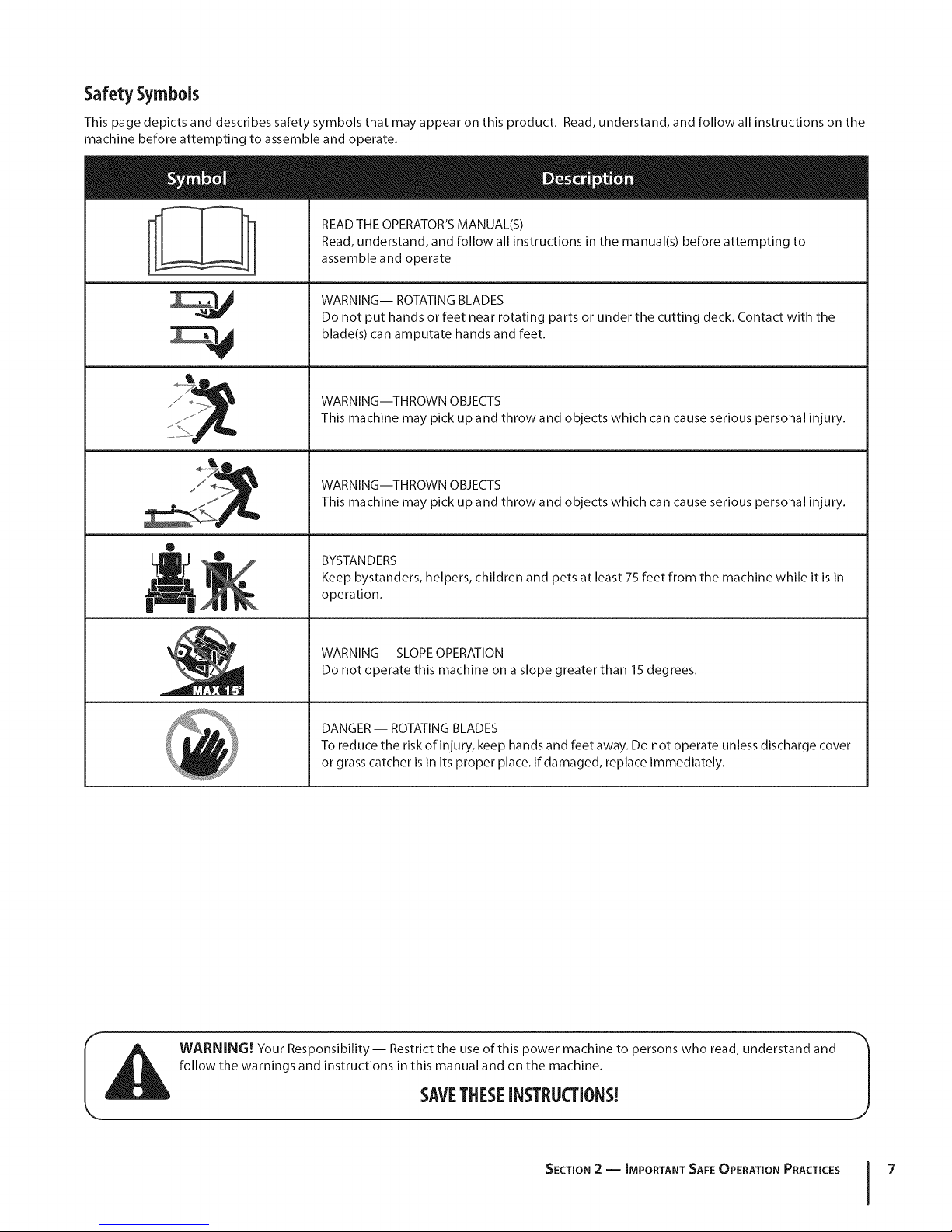
Safety Symbols
This page depicts and describes safety symbols that may appear on this product. Read, understand, and follow all instructions on the
machine before attempting to assemble and operate.
READ THE OPERATOR'S MANUAL(S)
Read, understand, and follow all instructions in the manual(s) before attempting to
assemble and operate
M
®
!!l"
N
WARNING-- ROTATING BLADES
Do not put hands or feet near rotating parts or under the cutting deck. Contact with the
blade(s) can amputate hands and feet.
WARNING--THROWN OBJECTS
This machine may pick up and throw and objects which can cause serious personal injury.
WARNING--THROWN OBJECTS
This machine may pick up and throw and objects which can cause serious personal injury.
BYSTANDERS
Keep bystanders, helpers, children and pets at least 75 feet from the machine while it is in
operation.
WARNING-- SLOPE OPERATION
Do not operate this machine on a slope greater than 15 degrees.
DANGER -- ROTATING BLADES
To reduce the risk of injury, keep hands and feet away. Do not operate unless discharge cover
or grass catcher is in its proper place. If damaged, replace immediately.
WARNING! Your Responsibility-- Restrict the use of this power machine to persons who read, understand and
follow the warnings and instructions in this manual and on the machine.
SAVETHESEINSTRUCTIONS!
SECTION 2 -- IMPORTANT SAFE OPERATION PRACTICES 7
Page 8
co
R
-4
6
Z
I
o
6
Z
-4
!
|
|
|
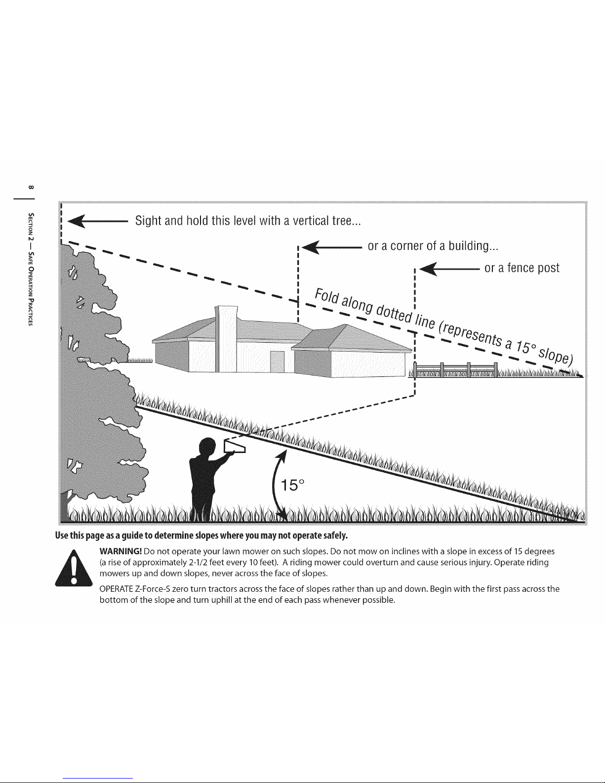
or a corner of a building...
|
15°
Usethis page as a guide to determine slopeswhere you may not operate safely.
WARNING! Do not operate your lawn mower on such slopes. Do not mow on inclines with a slope in excess of 15 degrees
(a rise of approximately 2-1/2 feet every 10 feet). A riding mower could overturn and cause serious injury. Operate riding
mowers up and down slopes, never across the face of slopes.
OPERATE Z-Force-S zero turn tractors across the face of slopes rather than up and down. Begin with the first pass across the
bottom of the slope and turn uphill at the end of each pass whenever possible.
Page 9
Assembly& Set-Up
Contents of Crate
3
One Lawn Tractor
One Z-Force-S Tractor Operator's
Manual
One Oil Drain Hose
One Engine Operator's Manual
TractorPreparation
1. Remove the upper crating material from the shipping pallet,
and cut any bands or tie straps securing the tractor to the
pallet.
2. If the deck is not in the highest mowing position (pushed all
the way forward), use the deck lift pedal to raise the deck to
its highest position. Refer to the Controls & Features section
for instructions on raising and lowering the deck.
3. Disengage the parking brake.
4. Engage the transmission bypass rods on each side of the
tractor; then carefully roll the tractor offthe shipping pallet.
The transmission bypass rods (one for each the RH and LH
transmission) are located on the rear of the tractor, just
inside each rear wheel. Disengage the bypass rods. See Fig.
3-1.
One Deck Wash Hose Coupler
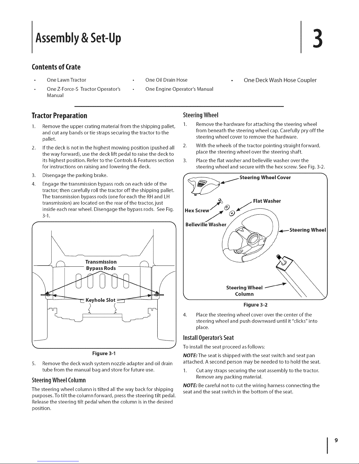
SteeringWheel
Remove the hardware for attaching the steering wheel
from beneath the steering wheel cap. Carefully pry off the
steering wheel cover to remove the hardware.
2.
With the wheels of the tractor pointing straight forward,
place the steering wheel over the steering shaft.
3. Place the flat washer and belleville washer over the
steering wheel and secure with the hex screw. See Fig. 3-2.
_ Steering Wheel Cover "_
Flat Washer
Belleville Wash_ Steering Wheel
Figure 3=1
5. Remove the deck wash system nozzle adapter and oil drain
tube from the manual bag and store for future use.
SteeringWheel Column
The steering wheel column is tilted all the way back for shipping
purposes. To tilt the column forward, press the steering tilt pedal.
Release the steering tilt pedal when the column is in the desired
position.
Steering Wheel /
Figure 3-2
4.
Place the steering wheel cover over the center of the
steering wheel and push downward until it "clicks" into
place.
Install Operator'sSeat
To install the seat proceed as follows:
NOTE:The seat is shipped with the seat switch and seat pan
attached. A second person may be needed to to hold the seat.
I. Cut any straps securing the seat assembly to the tractor.
Remove any packing material.
NOTE: Be careful not to cut the wiring harness connecting the
seat and the seat switch in the bottom of the seat.
Page 10
2. Removethetwoshoulderboltsandlocknutsintheseat
panasshowninFig.3-3.
Figure 3-3
3.
Rotate the seat into position and secure the seat into place
with the previously removed shoulder bolts and lock nuts.
Be careful not to crimp or damage the wire harness while
installing the seat. See Fig. 3-4.
Connectingthe Battery Cables
Battery posts, terminals, and related accessories
CALIFORNIA PROPOSITION 65 WARNING!
contain lead and lead compounds, chemicals known
to the State of California to cause cancer and
reproductive harm. Wash hands after handling.
connect the POSITIVE (Red) wire to its terminal first,
CAUTION: When attaching battery cables, always
followed by the NEGATIVE (Black) wire.
For shipping reasons, both battery cables on your equipment
may have been left disconnected from the terminals at the
factory. To connect the battery cables, proceed as follows:
NOTE:The positive battery terminal is marked Pos. (+). The
negative battery terminal is marked Neg. (-).
NOTE: If the positive battery cable is already attached, skip
ahead to step 2.
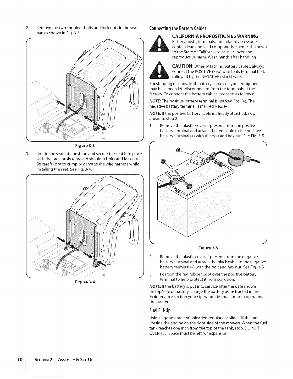
1. Remove the plastic cover, if present, from the positive
battery terminal and attach the red cable to the positive
battery terminal (+) with the bolt and hex nut. See Fig. 3-5.
F
Figure 3-4
SECTION 2-- ASSEMBLY& SET-UP
Figure 3-5
2. Remove the plastic cover, if present, from the negative
battery terminal and attach the black cable to the negative
battery terminal (-) with the bolt and hex nut. See Fig. 3-5.
3. Position the red rubber boot over the positive battery
terminal to help protect it from corrosion.
NOTE: If the battery is put into service after the date shown
on top/side of battery, charge the battery as instructed in the
Maintenance section your Operator's Manual prior to operating
the tractor.
FuelFill-Up
Using a good grade of unleaded regular gasoline, fill the tank
(beside the engine on the right side of the mower). When the fuel
tank reaches one inch from the top of the tank, stop, DO NOT
OVERFILL. Space must be left for expansion.
Page 11
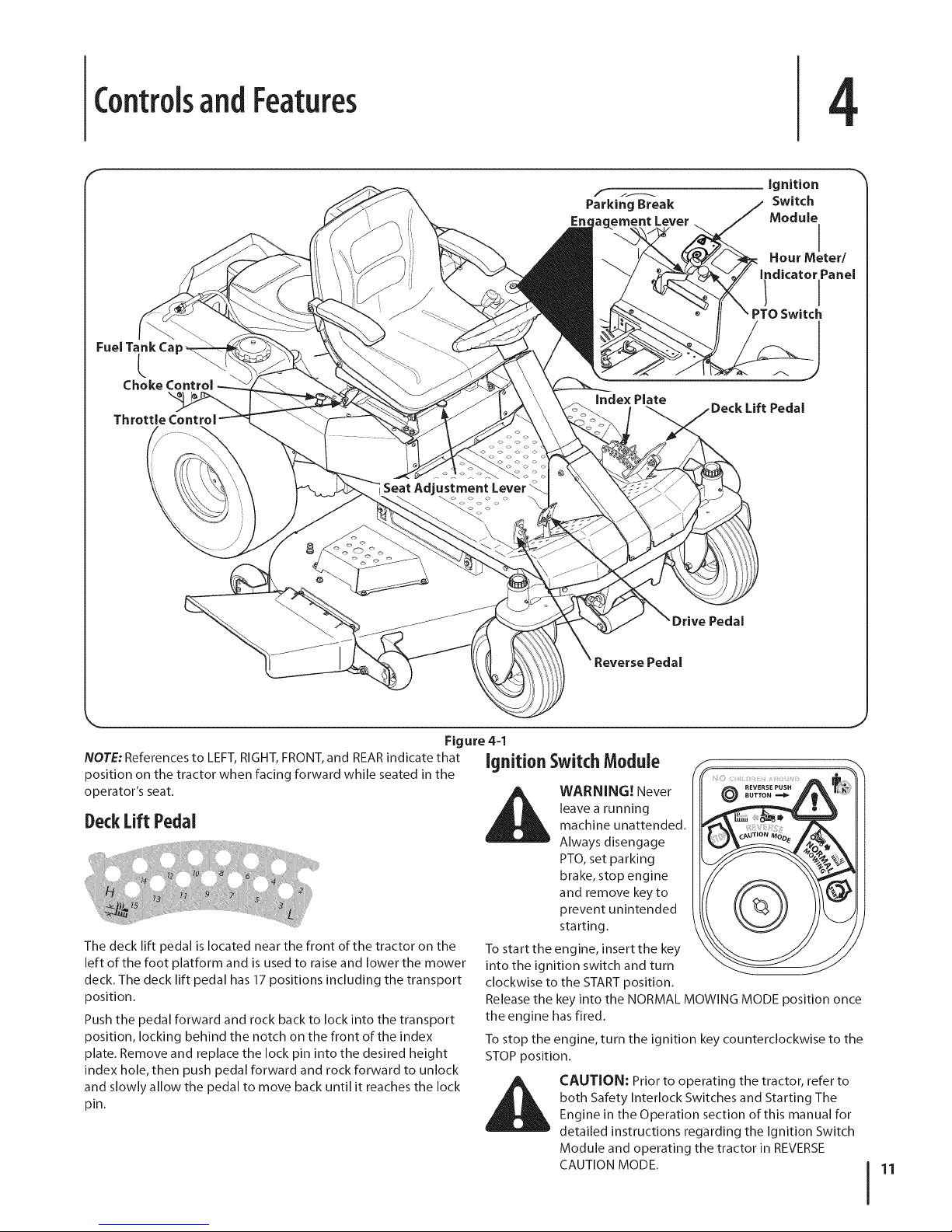
ControlsandFeatures
4
Fuel Tank Ca
f J_
Parking Break
Eric ement Lever
Ignition
Switch
Module
I
Hour Meter/
indicator Panel
NOTE: References to LEFT, RIGHT, FRONT, and REAR indicate that
position on the tractor when facing forward while seated in the
operator's seat.
DeckLift Pedal
The deck lift pedal is located near the front of the tractor on the
left of the foot platform and is used to raise and lower the mower
deck. The deck lift pedal has 17 positions including the transport
position.
Push the pedal forward and rock back to lock into the transport
position, locking behind the notch on the front of the index
plate. Remove and replace the lock pin into the desired height
index hole, then push pedal forward and rock forward to unlock
and slowly allow the pedal to move back until it reaches the lock
pin.
Reverse Pedal
Figure 4=1
Ignition SwitchModule
WARNING! Never
leave a running
machine unattended.
Always disengage
PTO, set parking
brake, stop engine
and remove key to
prevent unintended
starting.
To start the engine, insert the key
into the ignition switch and turn
clockwise to the START position.
Release the key into the NORMAL MOWING MODE position once
the engine has fired.
To stop the engine, turn the ignition key counterclockwise to the
STOP position.
CAUTION: Prior to operating the tractor, refer to
both Safety Interlock Switches and Starting The
Engine in the Operation section of this manual for
detailed instructions regarding the Ignition Switch
Module and operating the tractor in REVERSE
CAUTION MODE.
©
11
Page 12

PTO(PowerTake-Off)Switch
The PTO switch is located on the LH console to
the left of the operator's seat.
The PTO switch operates the electric PTO
clutch mounted on the bottom of the engine
crankshaft. Pull the switch knob upward to
engage the PTO clutch, or push the knob
downward to disengage the clutch.
The PTO switch must be in the "disengaged"
position when starting the engine.
PTO
• t
0 -I
Transmission BypassRods(Not Visible)
The transmission bypass rods (one for each the RH and LH
transmission) are located on the rear of the tractor, just inside
each rear wheel, below the fuel tank and the storage tray.
When engaged, the two rods open a bypass within the
hydrostatic transmissions, which allows the tractor to be pushed
short distances by hand.
tractor with the rear wheels on the ground may
CAUTION: Never tow your tractor. Towing the
cause severe damage to the transmissions.
CupHolder
The cup holder is located on the LH console to the left of the
operator's seat.
StorageTray
The storage tray is located at the rear of the LH console.
SeatAdjustment Lever
The seat adjustment lever is located below the front/left of the
seat. The lever a Ilows for adjustment of the fore to aft position
of the operator's seat. Refer to the Maintenance & Adjustments
section for instructions on adjusting the seat position.
FuelTankCap
The fuel tank cap is located on the LH console. Turn the fill cap to
remove. Always re-install the fuel cap tightly onto the fuel tank
after removing.
is running. If the engine is hot from recently running,
_ ARNING! Never fill the fuel tank when the engine
allow to cool for several minutes before refueling.
Highly flammable gasoline could splash onto the
engine and cause a fire.
HourMeter/IndicatorPanel
The hour meter/indicator panel is
located on the LH console to the left of
the operator's seat.
HourMeter Features
The hour meter records the hours that
the tractor has been operated in the
digital display (tenths of an hour- right
most digit).
NOTE:The hour meter is activated whenever the ignition switch
is turned to the "ON" position. Keep a record of the actual hours
of operation to assure all maintenance procedures are completed
according to the instructions in this manual and the engine
manual.
When key is turned to the "ON" position, the battery indicator
light briefly illuminates and the battery voltage is briefly
displayed. The display then changes to the accumulated hours.
The Indicator Monitor will also remind the operator of
maintenance intervals for changing the engine oil. The LCD
will alternately flash, "CHG" ; "OIL" and the recorded hours for
five minutes after every 50 hours of recorded operation. The
maintenance interval lasts for two hours (from 50-52,100-102,
150-152, etc.). The LCD will flash as described for five minutes
every time the tractor's engine is started during this maintenance
interval. Follow the oil change intervals provided in the engine
manual.
12 I SECTION 4-- CONTROLS AND FEATURES
Page 13
Indicator Panel Features
Battery Indicator
Illuminates and the battery voltage is displayed briefly when the
ignition switch it turned to the "ON" position.
Illuminates to indicate the battery voltage has dropped below
11.5 (+0.5/-1.0) volts. The battery voltage is aIso displayed on
the hour meter. If this indicator and display come on during
operation, check the battery and charging system for possible
causes and/or contact your Cub Cadet dealer.
Oil Pressure Indicator (If Engine So Equipped)
This warning lamp indicates low engine oil pressure. If the
indicator comes on while the engine is running, stop the engine
immediately and check for possible causes. Do not run the
engine while this indicator is illuminated. Contact your Cub
Cadet dealer to have the tractor and engine inspected.
NOTE:The oil pressure indicator may illuminate when the
ignition switch is in the ON position, but should turn offwhen
the engine is started.
PTO Engaged Indicator
This indicator illuminates when the PTO switch is pulled upward
in the "ENGAGED" position and the ignition switch is turned
to the "START" position. Check this indicator if the engine will
not crank with the ignition switch in the "START" position. If
necessary, move the PTO switch to the "DISENGAGED" position.
Parking Brake Engaged Indicator
This indicator illuminates when the parking brake is in the
DISENGAGED position and the ignition switch is turned to the
"START" position. Check this indicator if the engine will not crank
with the ignition switch in the "START" position. If necessary,
move the parking brake to the ENGAGED position.
This indicator also illuminates when the ignition switch is turned
to the "START" position and the RH and/or LH drive control levers
are in a position other than the fully out in neutral position. Move
the control levers fully outward.
ThrottleControl
The throttle control is located on the RH console
to the right of the operator's seat. When set in a
given position, a uniform engine speed will be
maintained.
Push the throttle control handle forward to increase
the engine speed. The tractor is designed to operate
with the throttle control in the fast position (full _lh
throttle) when the tractor is being driven and the
mower deck is engaged.
Pull the throttle control handle rearward to decrease the engine
speed.
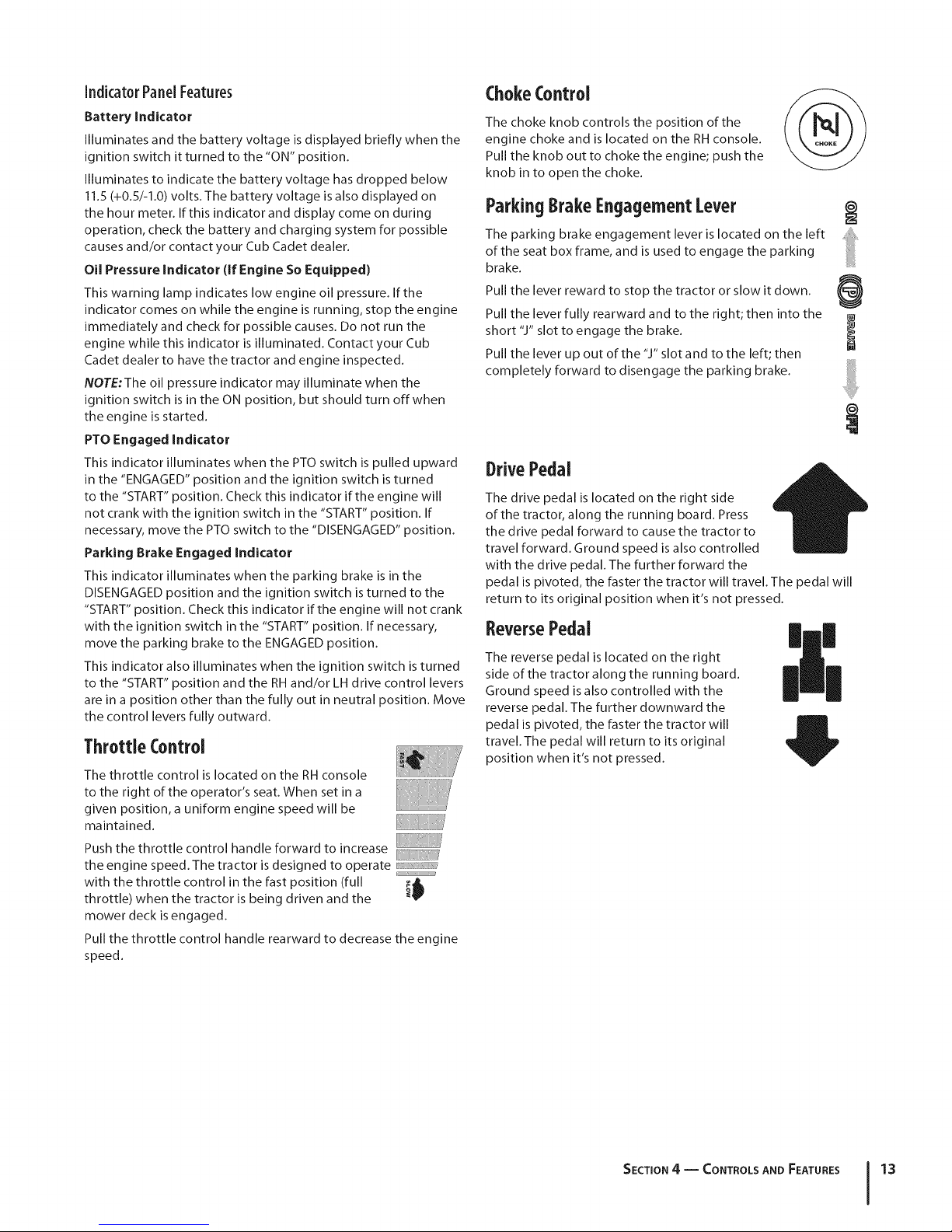
ChokeControl
The choke knob controls the position of the
engine choke and is located on the RH console.
Pull the knob out to choke the engine; push the
knob in to open the choke.
ParkingBrakeEngagementLever
The parking brake engagement lever is located on the left
of the seat box frame, and is used to engage the parking
brake.
Pull the lever reward to stop the tractor or slow it down.
Pull the lever fully rearward and to the right; then into the
short "J" slot to engage the brake.
Pull the lever up out of the "J" slot and to the left; then
completely forward to disengage the parking brake.
DrivePedal
The drive pedal is located on the right side
of the tractor, along the running board. Press
the drive pedal forward to cause the tractor to
travel forward. Ground speed is also controlled
with the drive pedal. The further forward the
pedal is pivoted, the faster the tractor will travel. The pedal will
return to its original position when it's not pressed.
ReversePedal
The reverse pedal is located on the right
side of the tractor along the running board.
Ground speed is also controlled with the
reverse pedal. The further downward the
pedal is pivoted, the faster the tractor will
travel. The pedal will return to its original
position when it's not pressed.
|
SECTION4 -- CONTROLS AND FEATURES 13
Page 14
Operation
5
GeneralSafety
RECEIVE INSTRUCTION -- Entirely read this operator's
manual. Learn to operate this machine SAFELY. Do not risk
INJURY or DEATH. Allow only those who have become
competent in its usage to operate this tractor.
Before starting the engine or beginning operation, be
familiar with the controls. The operator should be in the
operator's seat. The PTO switch must be in the disengaged
position and the parking brake engaged.
Keep all shields in place. Keep away from moving parts.
NO RIDERS! Keep all people and pets a safe distance away.
Look behind and down to both sides of the tractor before
and while backing up.
DO NOT direct the mower discharge at people.
Avoid slopes where possible. Never operate on slopes
greater than 15°. Slopes with a greater incline present
dangerous operating conditions. Tractors can be rolled
over.
Before leaving the operator's seat: Shut off the PTO and
engage the parking brake, shut off the engine and remove
the ignition key. Wait for all movement to stop before
servicing or cleaning.
Avoid any sudden movements of the steering wheel when
starting and stopping. Keep a firm grip on the steering
wheel.
Be careful when operating near roadways. Stop the tractor
motion and wait for vehicles to pass before operating
along the road.
Do not operate the tractor with the mower deck removed.
Removal of the deck will change the balance of the tractor,
and could contribute to a tractor rollover.
Avoid operation on traction surfaces that are unstable; use
extreme caution if the surface is slippery.
Slow down before turning and come to a complete stop
before any zero turn maneuver.
Do not stop the tractor or park the tractor over
combustible materials such as dry grass, leaves, debris, etc.
Do not fill the fuel tank when the engine is running or
while the engine is hot. Allow the engine several minutes
to cool before refueling. Tighten the fuel cap securely.
BeforeOperatingYourTractor
Before you operate the tractor, study this manual carefully
to familiarize yourself with the operation of all the
instruments and controls. It has been prepared to help you
operate and maintain your tractor efficiently.
This engine is certified to operate only on clean, fresh,
unleaded regular gasoline. For best results, fill the fuel
tank with only clean, fresh, unleaded gasoline with a pump
sticker octane rating of 87 or higher.
Unleaded gasoline is recommended because it leaves
less combustion chamber deposits and reduces harmful
exhaust emissions. Leaded gasoline is not recommended
and must not be used where exhaust emissions are
regulated.
NOTE: Purchase gasoline in small quantities. Do not use
gasoline left over from the previous season, to minimize
gum deposits in the fuel system.
Gasohol (up to 10% ethyl alcohol, 90% unleaded gasoline
by volume) is an approved fuel. Other gasoline/alcohol
blends are not approved.
Methyl Tertiary Butyl Ether (MTBE) and unleaded gasoline
blends (up to a maximum of 15% MTBE by volume) are
approved fuels. Other gasoline/ether blends are not
approved.
Check the engine oil level.
Clean the air cleaner element if necessary.
Check the tire inflation pressures.
Adjust the seat for operator's maximum comfort, visibility
and for maintaining complete control of the tractor.
SafetyInterlock Switches
This tractor is equipped with a safety interlock system for the
protection of the operator. If the interlock system should ever
malfunction, do not operate the tractor. Contact your Cub Cadet
dealer.
The safety interlock system prevents the engine from
cranking or starting unless the parking brake is engaged,
and the PTO (Blade Engage) knob is in the disengaged
(OFF) position.
The engine will automatically shut off if the operator leaves
the seat before engaging the parking brake.
interlock system is malfunctioning. This system was
WARNING! Do not operate the tractor if the
designed for your safety and protection.
Page 15
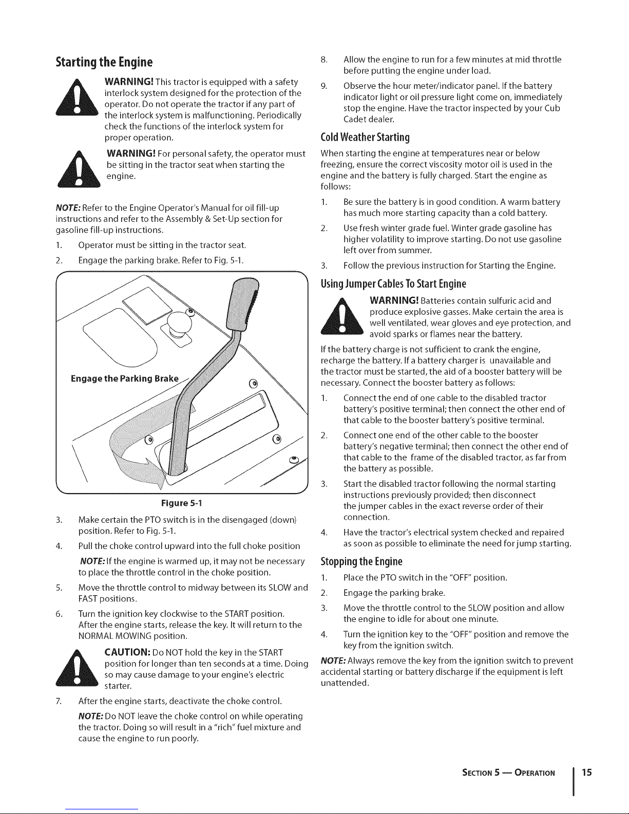
Startingthe Engine
WARNING! This tractor is equipped with a safety
interlock system designed for the protection of the
operator. Do not operate the tractor if any part of
the interlock system is malfunctioning. Periodically
check the functions of the interlock system for
proper operation.
WARNING! For personal safety, the operator must
be sitting in the tractor seat when starting the
engine.
NOTE: Refer to the Engine Operator's Manual for oil fill-up
instructions and refer to the Assembly & Set-Up section for
gasoline fill-up instructions.
1. Operator must be sitting in the tractor seat.
2. Engage the parking brake. Refer to Fig. 5-1.
Figure 5-1
3. Make certain the PTO switch is in the disengaged (down)
position. Refer to Fig. 5-1.
4. Pull the choke control upward into the full choke position
NOTE: If the engine is warmed up, it may not be necessary
to place the throttle control in the choke position.
5. Move the throttle control to midway between its SLOW and
FAST positions.
6. Turn the ignition key clockwise to the START position.
After the engine starts, release the key. It will return to the
NORMAL MOWING position.
CAUTION: Do NOT hold the key in the START
position for longer than ten seconds at a time. Doing
so may cause damage to your engine's electric
starter.
After the engine starts, deactivate the choke control.
NOTE: Do NOT leave the choke control on while operating
the tractor. Doing so will result in a "rich" fuel mixture and
cause the engine to run poorly.
8.
Allow the engine to run for a few minutes at mid throttle
before putting the engine under load.
9.
Observe the hour meter/indicator panel. If the battery
indicator light or oil pressure light come on, immediately
stop the engine. Have the tractor inspected by your Cub
Cadet dealen
C01dWeatherStarting
When starting the engine at temperatures near or below
freezing, ensure the correct viscosity motor oil is used in the
engine and the battery is fully charged. Start the engine as
follows:
1. Be sure the battery is in good condition. A warm battery
has much more starting capacity than a cold battery.
2. Use fresh winter grade fuel. Winter grade gasoline has
higher volatility to improve starting. Do not use gasoline
left over from summer.
3. Follow the previous instruction for Starting the Engine.
UsingJumperCablesToStart Engine
produce explosive gasses. Make certain the area is
WARNING! Batteries contain sulfuric acid and
well ventilated, wear gloves and eye protection, and
avoid sparks or flames near the battery.
If the battery charge is not sufficient to crank the engine,
recharge the battery. Ira battery charger is unavailable and
the tractor must be started, the aid of a booster battery will be
necessary. Connect the booster battery as follows:
I. Connect the end of one cable to the disabled tractor
battery's positive terminal; then connect the other end of
that cable to the booster battery's positive terminal.
2. Connect one end of the other cable to the booster
battery's negative terminal; then connect the other end of
that cable to the frame of the disabled tractor, as far from
the battery as possible.
3. Start the disabled tractor following the normal starting
instructions previously provided; then disconnect
the jumper cables in the exact reverse order of their
connection.
4.
Have the tractor's electrical system checked and repaired
as soon as possible to eliminate the need for jump starting.
Stoppingthe Engine
I. Place the PTO switch in the "OFF" position.
2. Engage the parking brake.
3. Move the throttle control to the SLOW position and allow
the engine to idle for about one minute.
4. Turn the ignition key to the "OFF" position and remove the
key from the ignition switch.
NOTE: Always remove the key from the ignition switch to prevent
accidental starting or battery discharge if the equipment is left
unattended.
SECTION S -- OPERATION 15
Page 16
DrivingTheTractor
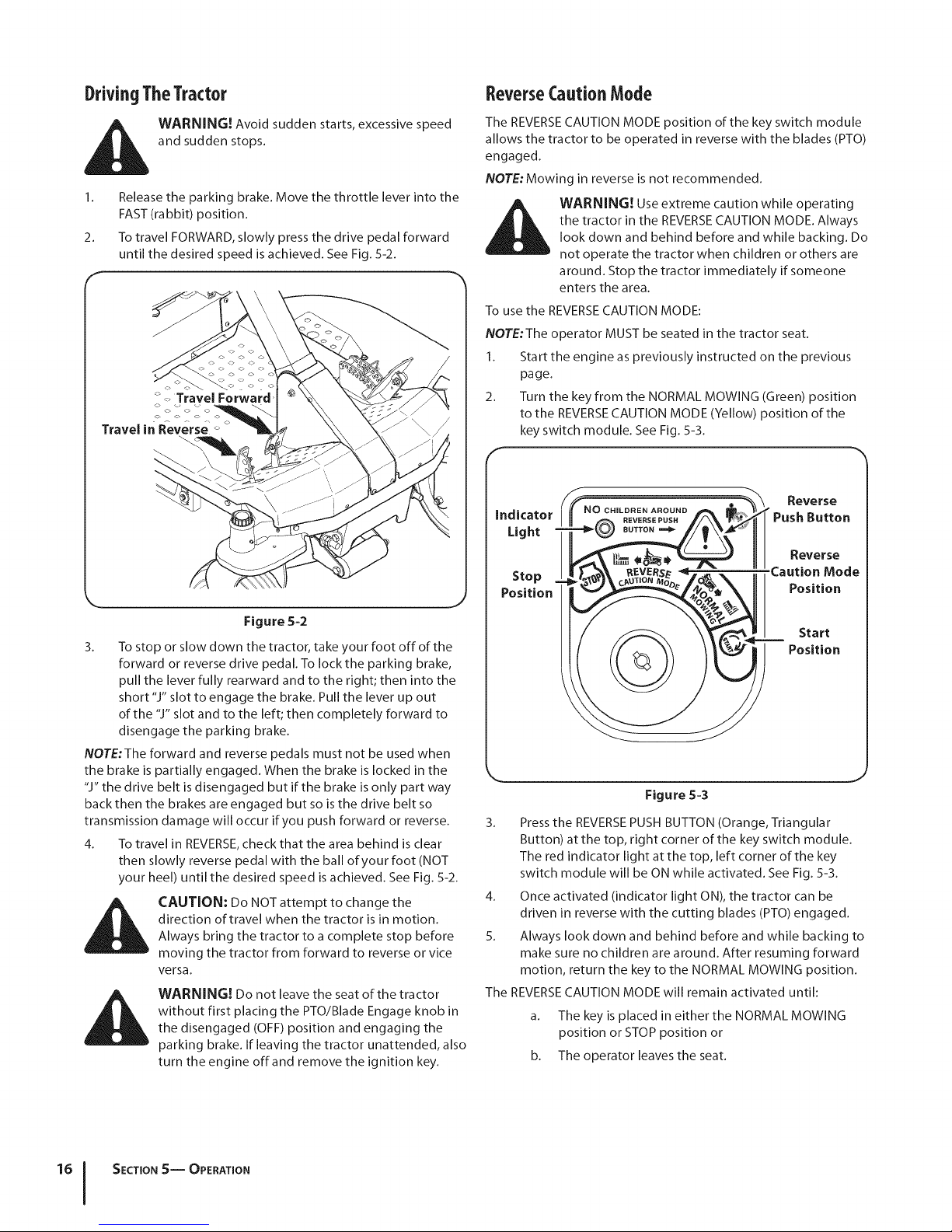
i_lk WARNING! Avoid sudden starts, excessive speed
1. Release the parking brake. Move the throttle lever into the
2. To travel FORWARD, slowly press the drive pedal forward
Travel in Reverse _
and sudden stops.
FAST (rabbit) position.
until the desired speed is achieved. See Fig. 5-2.
<>
_ Travel Forward'
ReverseCautionMode
The REVERSE CAUTION MODE position of the key switch module
allows the tractor to be operated in reverse with the blades (PTO)
engaged.
NOTE: Mowing in reverse is not recommended.
the tractor in the REVERSECAUTION MODE. Always
WARNING! Use extreme caution while operating
look down and behind before and while backing. Do
not operate the tractor when children or others are
around. Stop the tractor immediately if someone
enters the area.
To use the REVERSECAUTION MODE:
NOTE:The operator MUST be seated in the tractor seat.
1. Start the engine as previously instructed on the previous
page.
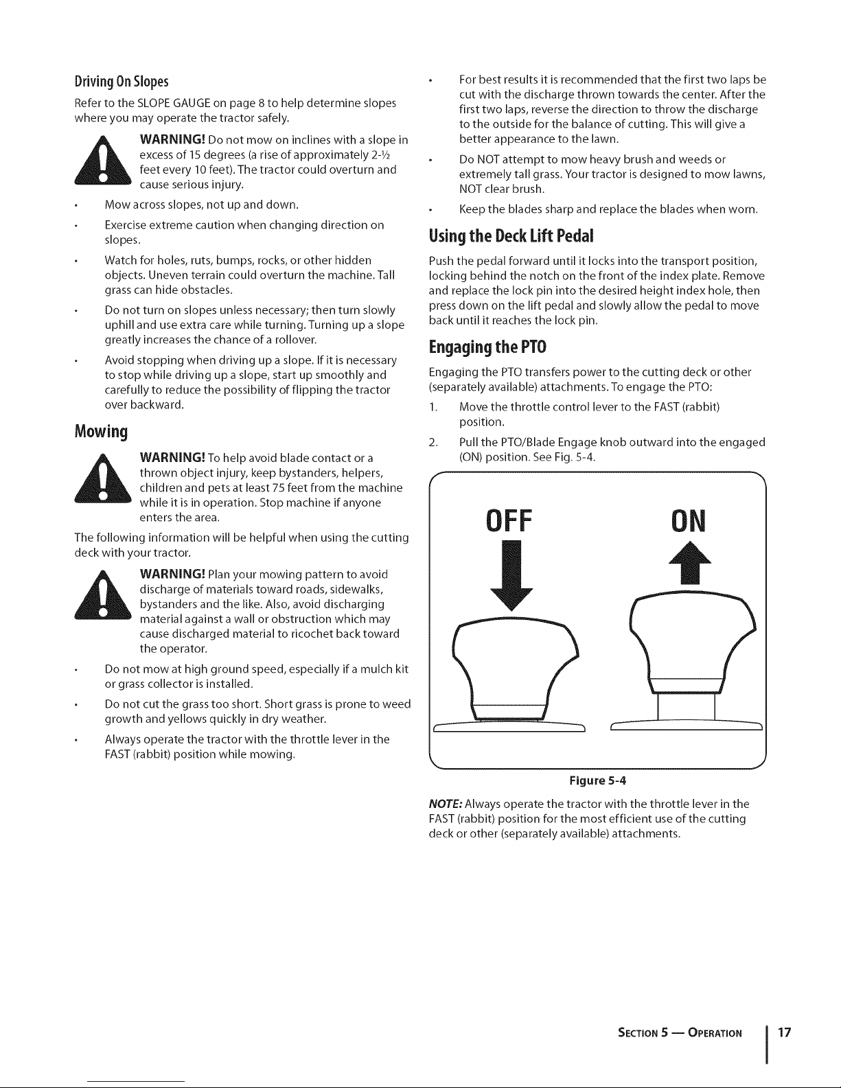
2. Turn the key from the NORMAL MOWING (Green) position
to the REVERSECAUTION MODE (Yellow) position of the
key switch module. See Fig. 5-3.
F
Figure 5-2
3. To stop or slow down the tractor, take your foot off of the
forward or reverse drive pedal. To lock the parking brake,
pull the lever fully rearward and to the right; then into the
short"J" slot to engage the brake. Pull the lever up out
of the "J" slot and to the left; then completely forward to
disengage the parking brake.
NOTE:The forward and reverse pedals must not be used when
the brake is partially engaged. When the brake is locked in the
"J" the drive belt is disengaged but if the brake is only part way
back then the brakes are engaged but so is the drive belt so
transmission damage will occur if you push forward or reverse.
4. To travel in REVERSE, check that the area behind is clear
then slowly reverse pedal with the ball of your foot (NOT
your heel) until the desired speed is achieved. See Fig. 5-2.
direction of travel when the tractor is in motion.
i_ CAUTION: Do NOT attempt to change the
Always bring the tractor to a complete stop before
moving the tractor from forward to reverse or vice
versa.
WARNING! Do not leave the seat of the tractor
without first placing the PTO/Blade Engage knob in
the disengaged (OFF) position and engaging the
parking brake. If leaving the tractor unattended, also
turn the engine offand remove the ignition key.
Indicator CHILDREN AROUND
Light BUTTON===_
Stop
Position
REVERSEPUSH
e
Reverse
PushButton
Reverse
Caution Mode
Position
Position
Start
k. j
Figure 5-3
3. Press the REVERSE PUSH BUTTON (Orange, Triangular
Button) at the top, right corner of the key switch module.
The red indicator light at the top, left corner of the key
switch module will be ON while activated. See Fig. 5-3.
4. Once activated (indicator light ON), the tractor can be
driven in reverse with the cutting blades (PTO) engaged.
5. Always look down and behind before and while backing to
make sure no children are around. After resuming forward
motion, return the key to the NORMAL MOWING position.
The REVERSE CAUTION MODE will remain activated until:
a. The key is placed in either the NORMAL MOWING
position or STOP position or
b. The operator leaves the seat.
SECTION S-- OPERATION
Page 17
DrivingOnSlopes
Refer to the SLOPE GAUGE on page 8 to help determine slopes
where you may operate the tractor safely.
i_ WARNING! Do not mow on inclines with a slope in
excess of 15 degrees (a rise of approximately 2-1/2
feet every 10 feet). The tractor could overturn and
cause serious injury.
Mow across slopes, not up and down.
Exercise extreme caution when changing direction on
slopes.
Watch for holes, ruts, bumps, rocks, or other hidden
objects. Uneven terrain could overturn the machine. Tall
grass can hide obstacles.
Do not turn on slopes unless necessary; then turn slowly
uphill and use extra care while turning. Turning up a slope
greatly increases the chance ofa rollover.
Avoid stopping when driving up a slope. If it is necessary
to stop while driving up a slope, start up smoothly and
carefully to reduce the possibility of flipping the tractor
over backward.
Mowing
WARNING! To help avoid blade contact or a
thrown object injury, keep bystanders, helpers,
children and pets at least 75 feet from the machine
while it is in operation. Stop machine if anyone
enters the area.
The following information will be helpful when using the cutting
deck with your tractor.
discharge of materials toward roads, sidewalks,
WARNING! Plan your mowing pattern to avoid
bystanders and the like. Also, avoid discharging
material against a wall or obstruction which may
cause discharged material to ricochet back toward
the operator.
Do not mowat high ground speed, especially ira mulch kit
or grass collector is installed.
Do not cut the grass too short. Short grass is prone to weed
growth and yellows quickly in dry weather.
Always operate the tractor with the throttle lever in the
FAST (rabbit) position while mowing.
For best results it is recommended that the first two laps be
cut with the discharge thrown towards the center. After the
first two laps, reverse the direction to throw the discharge
to the outside for the balance of cutting. This will give a
better appearance to the lawn.
Do NOT attempt to mow heavy brush and weeds or
extremely tall grass. Your tractor is designed to mow lawns,
NOT clear brush.
Keep the blades sharp and replace the blades when worn.
Usingthe DeckLiftPedal
Push the pedal forward until it locks into the transport position,
locking behind the notch on the front of the index plate. Remove
and replace the lock pin into the desired height index hole, then
press down on the lift pedal and slowly allow the pedal to move
back until it reaches the lock pin.
Engagingthe PTO
Engaging the PTO transfers power to the cutting deck or other
(separately available) attachments. To engage the PTO:
1. Move the throttle control lever to the FAST (rabbit)
position.
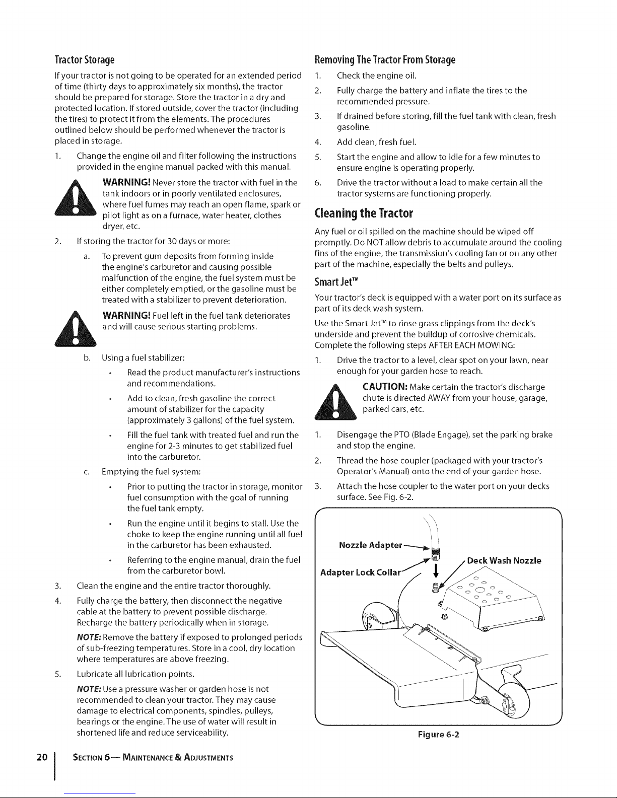
2. Pull the PTO/Blade Engage knob outward into the engaged
(ON) position. See Fig. 5-4.
OFF
ON
t
Figure 5-4
NOTE: Always operate the tractor with the throttle lever in the
FAST (rabbit) position for the most efficient use of the cutting
deck or other (separately available) attachments.
J
SECTION S -- OPERATION 17
Page 18

Maintenance&Adjustments
MaintenanceSchedule
6
Before
Eachuse
CheckEngineOilLevel y / y /
CheckAirFilterfor Dirty, LooseorDamagedParts _
CleanandRe-oilAirFilter'sFoamPredeaner _/
ReplaceAirFilterElement V /
ChangeEngineOiland ReplaceOilFilter _/
CleanBattery Terminals _" _"
LubeFrontCasterWheelsandWheelSpindles y / y /
CheckEngineCoolingFinsfor Debris(Cleanas V/ V/
Neccasary)
LubeDeckSpindles _
LubePedalPivotPoints _
Every
10Hours
Every
25Hours
Every
SOHours
Every
100Hours
Prior
toStoring
CheckSparkPlugCondition&Gap _
ReplaceFuelFilter
Maintenance
WARNING! Before performing any maintenance or
repairs, disengage PTO, set parking brake, stop
engine and remove key to prevent unintended
starting.
Refer to the Kawasaki Owner's Manual for all engine maintenance
procedures and instructions.
NOTE: Maintenance, repair, or replacement of the emission
control devices and systems which are being done at owner's
expense may be performed by any engine repair establishment
or individual. Warranty repairs must be performed by a Cub
Cadet Dealer.
Changingthe EngineOil
engine, muffler and surrounding metal surfaces will
_ ARNING! If the engine has been recently run, the
NOTE:The oil filter should be changed at every oil change
interval.
To complete an oil change, proceed as follows:
1. Run the engine for a short time to warm the engine oil. The
2. Locate the oil drain port on the right side of the engine.
be hot and can cause burns to the skin. Exercise
caution to avoid burns.
oil will flow more freely and carry away more impurities.
Use care to avoid burns from hot oil.
Page 19

3.
Pop open the protective cap on the end of the oil drain
valve to expose the drain port. Refer to Figure 6-1. Remove
the oil fill cap/dipstick from the oil fill tube.
Figure 6-1
4. Push the oil drain hose (packed with this manual) onto the
oil drain port. Route the opposite end of the hose into an
appropriate oil collection container with at least a 2.0 quart
capacity, to collect the used oil.
5. Turn the oil drain valve 1/4-turn, then pull outward to begin
draining oil. After the oil has finished draining, push the
end of the oil drain valve back in and turn 1/4-turn to secure
it back in place. Re-cap the end of the oil drain valve to
keep debris from entering the drain port.
6. After the oil has finished draining, push the end of the oil
drain valve back in, until the tabs click into place. Re-cap
the end of the oil drain valve to keep debris from entering
the drain port.
7. Replace the oil filter, and refill the engine with new oil as
instructed in the Kawasaki Owner's Manual.
Air (:leaner
Service the pre-cleaner and cartridge/air cleaner element as
instructed in the Kawasaki Owner's Manual.
SparkPlug(s)
The spark plug should be cleaned and the gap reset once a
season. Refer to the Kawasaki Owner's Manual for correct plug
type and gap specifications.
Hydrostatic Transmission
The hydrostatic transmission is sealed at the factory and is
maintenance-free. The fluid level cannot be checked and the
fluid cannot be changed.
Battery
Battery posts, terminals, and related accessories
CALIFORNIA PROPOSITION 65 WARNING!
contain lead and lead compounds, chemicals known
to the State of California to cause cancer and
reproductive harm. Wash hands after handling.
The battery is sealed and is maintenance-free. Acid levels cannot
be checked and fluid can not be added.
Always keep the battery cables and terminals clean and
free of corrosive build-up.
After cleaning the battery and terminals, apply a light coat
of petroleum jelly or grease to both terminals.
disconnect the NEGATIVE (Black) wire from its
CAUTION: If removing the battery for cleaning,
terminal first, followed by the POSITIVE (Red) wire.
When re-installing the battery, always connect the
POSITIVE (Red) wire its terminal first, followed by the
NEGATIVE (Black) wire. Be certain that the wires are
connected to the correct terminals; reversing them
could result in serious damage to your engine's
alternating system.
Battery Storage
1. When storing the tractor for extended periods, disconnect
the negative battery cable. It is not necessary to remove
the battery.
2. All batteries discharge during storage. Keep the exterior
of the battery clean, especially the top. A dirty battery will
discharge more rapidly.
3. The battery must be stored with a full charge. A discharged
battery can freeze sooner than a charged battery. A fully
charged battery will store longer in cold temperatures than
hot.
4.
Recharge the battery before returning to service. Although
the tractor may start, the engine charging system may not
fully recharge the battery.
SECTION 6 -- MAINTENANCE & ADJUSTMENTS 19
Page 20
TractorStorage
If your tractor is not going to be operated for an extended period
of time (thirty days to approximately six months), the tractor
should be prepared for storage. Store the tractor in a dry and
protected location. If stored outside, cover the tractor (including
the tires) to protect it from the elements. The procedures
outlined below should be performed whenever the tractor is
placed in storage.
1. Change the engine oil and filter following the instructions
provided in the engine manual packed with this manual.
WARNING! Never store the tractor with fuel in the
tank indoors or in poorly ventilated enclosures,
where fuel fumes may reach an open flame, spark or
pilot light as on a furnace, water heater, clothes
dryer, etc.
2_
If storing the tractor for 30 days or more:
a. To prevent gum deposits from forming inside
the engine's carburetor and causing possible
malfunction of the engine, the fuel system must be
either completely emptied, or the gasoline must be
treated with a stabilizer to prevent deterioration.
WARNING! Fuel left in the fuel tank deteriorates
and will cause serious starting problems.
b. Using a fuel stabilizer:
Read the product manufacturer's instructions
and recommendations.
Add to clean, fresh gasoline the correct
amount of stabilizer for the ca pacity
(approximately 3 gallons) of the fuel system.
Fill the fuel tank with treated fuel and run the
engine for 2-3 minutes to get stabilized fuel
into the carburetor.
Emptying the fuel system:
Prior to putting the tractor in storage, monitor
fuel consumption with the goal of running
the fuel tank empty.
Run the engine until it begins to stall. Use the
choke to keep the engine running until all fuel
in the carburetor has been exhausted.
Referring to the engine manual, drain the fuel
from the carburetor bowl.
3. Clean the engine and the entire tractor thoroughly.
4. Fully charge the battery, then disconnect the negative
cable at the battery to prevent possible discharge.
Recharge the battery periodically when in storage.
NOTE: Remove the battery if exposed to prolonged periods
of sub-freezing temperatures. Store in a cool, dry location
where temperatures are above freezing.
5. Lubricate all lubrication points.
NOTE: Use a pressure washer or garden hose is not
recommended to clean your tractor. They may cause
damage to electrical components, spindles, pulleys,
bearings or the engine. The use of water will result in
shortened life and reduce serviceability.
RemovingTheTractorFromStorage
1. Check the engine oil.
2. Fully charge the battery and inflate the tires to the
recommended pressure.
3. If drained before storing, fill the fuel tank with clean, fresh
gasoline.
4. Add clean, fresh fuel.
5. Start the engine and allow to idle for a few minutes to
ensure engine is operating properly.
6. Drive the tractor without a load to make certain all the
tractor systems are functioning properly.
Cleaningthe Tractor
Any fuel or oil spilled on the machine should be wiped off
promptly. Do NOT allow debris to accumulate around the cooling
fins of the engine, the transmission's cooling fan or on any other
part of the machine, especially the belts and pulleys.
Smart JetTM
Your tractor's deck is equipped with a water port on its surface as
part of its deck wash system.
Use the Smart Jet TM to rinse grass clippings from the deck's
underside and prevent the buildup of corrosive chemicals.
Complete the following steps AFTER EACH MOWING:
1. Drive the tractor to a level, clear spot on your lawn, near
enough for your garden hose to reach.
chute is directed AWAY from your house, garage,
CAUTION: Make certain the tractor's discharge
parked cars, etc.
1. Disengage the PTO (Blade Engage), set the parking brake
and stop the engine.
2. Thread the hose coupler (packaged with your tractor's
Operator's Manual) onto the end of your garden hose.
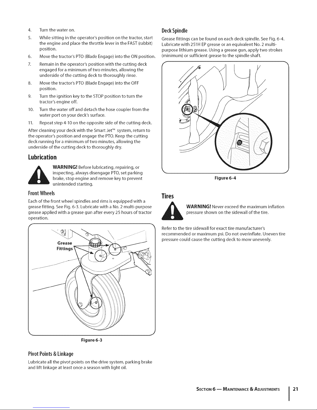
3. Attach the hose coupler to the water port on your decks
surface. See Fig. 6-2.
f
Nozzle Ada
Adapter
J
Figure 6-2
SECTION 6-- MAINTENANCE & ADJUSTMENTS
Page 21
4.
Turn the water on.
5.
While sitting in the operator's position on the tractor, start
the engine and place the throttle lever in the FAST (rabbit)
position.
6. Move the tractor's PTO (Blade Engage) into the ON position.
7. Remain in the operator's position with the cutting deck
engaged for a minimum of two minutes, allowing the
underside of the cutting deck to thoroughly rinse.
8. Move the tractor's PTO (Blade Engage) into the OFF
position.
9. Turn the ignition key to the STOP position to turn the
tractor's engine off.
10. Turn the water off and detach the hose coupler from the
water port on your deck's surface.
11. Repeat step 4-10 on the opposite side of the cutting deck.
After cleaning your deck with the Smart JetTM system, return to
the operator's position and engage the PTO. Keep the cutting
deck running for a minimum of two minutes, allowing the
underside of the cutting deck to thoroughly dry.
Lubrication
WARNING! Before lubricating, repairing, or
inspecting, always disengage PTO, set parking
brake, stop engine and remove key to prevent
unintended starting.
Front Wheels
Each of the front wheel spindles and rims is equipped with a
grease fitting. See Fig. 6-3. Lubricate with a No. 2 multi-purpose
grease applied with a grease gun after every 25 hours of tractor
operation.
f
_._ \_ ............i
Grease
Fittings _
DeckSpindle
Grease fittings can be found on each deck spindle. See Fig. 6-4.
Lubricate with 251H EP grease or an equivalent No. 2 multi-
purpose lithium grease. Using a grease gun, apply two strokes
(minimum) or sufficient grease to the spindle shaft.
f
Figure 6-4
WARNING! Never exceed the maximum inflation
pressure shown on the sidewall of the tire.
Refer to the tire sidewall for exact tire manufacturer's
recommended or maximum psi. Do not overinflate. Uneven tire
pressure could cause the cutting deck to mow unevenly.
k_ j
Figure 6-3
Pivot Points& Linkage
Lubricate all the pivot points on the drive system, parking brake
and lift linkage at least once a season with light oil.
SECTION 6 -- MAINTENANCE & ADJUSTMENTS 21
Page 22

Adjustments
NOTE: Check the tractor's tire pressure before performing
any deck leveling adjustments. Refer to Tires on page 21 for
information regarding tire pressure.
WARNING! Shut the engine off, remove the
ignition key and engage the parking brake before
making adjustments. Protect your hands by using
heavy gloves when handling the blades.
Levelingthe Deck(Sideto Side)
NOTE: Check the tractor's tire pressure before performing
any deck leveling adjustments. Refer to Tires on page 21 for
information regarding tire pressure. Always level the deck side to
side before front to rear.
NOTE:When leveling the deck side-to-side, make sure the two
rear adjustment gears are set in the middle of the adjustment
range.
If the cutting deck appears to be mowing unevenly, a side to side
adjustment can be performed. Adjust if necessary as follows:
1. With the tractor parked on a firm, level surface, place the
deck lift pedal in a middle mowing )osition and rotate
both outside blades so that they are perpendicular with the
tractor.
2. Measure the distance from the outside of the left blade
tip to the ground and the distance from the outside of the
right blade tip to the ground. Both measurements taken
should be equal. If they're not, proceed to the next step.
3. Loosen, but do NOT remove, the hex bolt on the front left
deck hanger link. See Fig. 6-5.
Levelingthe Deck(FrontToRear)
NOTE: Check the tractor's tire pressure before performing
any deck leveling adjustments. Refer to Tires on page 21 for
information regarding tire pressure. Always level the deck side to
side before front to rear.
The front of the deck should be between V4"and %" lower than
the rear of the deck. Adjust if necessary as follows:
1. Park the tractor on a firm, level surface and place the deck
lift pedal in a middle position.
2. Rotate the blade nearest the discharge chute so that it is
parallel with the tractor.
3. Measure the distance from the front of the blade tip to the
ground and the rear of the blade tip to the ground. The
first measurement taken should be between 1/4"and %" less
than the second measurement.
Determine the approximate distance necessary for proper
adjustment and proceed, if necessary.
4. Loosen, but do NOT remove, the hex bolt on the left and
right rear deck hanger brackets. See Fig. 6-5.
5. Using a wrench, raise or lower the left and right side of the
deck by turning the adjustment gears. See Fig. 6-5.
6. The deck is properly leveled when the front tip of the
blade is 1/4"lower tham the rear tip. Retighten the hex bolt
on the left and right rear deck hanger links when proper
adjustment is achieved.
Adjusting the Belt Tension
To tighten or loosen the tension on the belt, tighten or loosen
the jam nuts on the U-rod, see Fig. 6-6, until a ten-pound pull
with a spring scale deflects the belt about I/2".
f
\
Adj // ,
Gear / '
.......(
\ \_ \X
He× Bolt
Figure 6-5
NOTE:The front right deck hanger link is not adjustable
and is used to help adjust the other hanger links.
4. Using a wrench, raise or lower the left side of the deck by
turning the adjustment gears. See Fig. 6-5.
The deck is properly leveled when both blade tip measurements
are equal. Retighten the hex bolt on the front left deck hanger
bracket when proper adjustment is achieved.
SECTION 6-- MAINTENANCE & ADJUSTMENTS
Figure 6-6
Page 23

Setting the DeckWheels
Move the tractor on a firm and level surface, preferably
pavement, and proceed as follows
1. Select the height position of the cutting deck by placing
the deck lift pedal in the normally desired mowing height
setting.
2. Check the deck wheels for contact or excessive clearance
with the surface below. The deck wheels should have
between 1/4-1/2"clearance above the ground.
3. If the deck wheels have excessive clearance or contact with
the surface, adjust as follows:
a. Raise the deck lift pedal to its highest setting.
b. Remove the front and rear deck wheels by removing
the lock nuts and shoulder bolts which secure them
to the deck. See Fig. 6-7.
f
Deck Wheel
Parking BrakeAdjustment
If the tractor does not come to a complete stop when the brake
lever is completely engaged, or if the tractor's rea r wheels can
roll with the parking brake applied (and the hydrostatic relief
valve open), the brake is in need of adjustment. See your Cub
Cadet dealer to have the brake properly adjusted.
Adjusting the Seat
To adjust the position of the seat, push the seat adjustment lever
to the left. Slide the seat forward or rearward to the desired
position; then release the adjustment lever. Make sure seat is
locked into position before operating the tractor. See Fig. 6-8.
f
,%
Figure 6-7
C.
Place the deck lift pedal in the desired mowing
height setting.
d.
Reinsert the shoulder bolts (with each gauge wheel)
into the index hole that leaves approximately
1/2-inch between the bottom of the wheel and the
pavement.
Figure 6-8
SECTION 6 -- MAINTENANCE & ADJUSTMENTS 23
Page 24

Service
7
WARNING! Before performing any service, place
the PTO switch in the "OFF" position, engage the
parking brake lever, turn the ignition key to the
"OFF" position and remove the key from the switch.
Battery Removal
accessories contain lead and lead compounds. Wash
WARNING! Battery posts, terminals and related
hands after handling.
The battery is located beneath the seat box frame. To remove the
battery:
1. Push down and back on the battery hold-down bracket as
shown in Fig. 7-1 to free it from the seat mount frame.
Chargingthe Battery
Test and, if necessary, recharge the battery after the tractor has
been stored for a period of time.
A voltmeter or load tester should read 12.6 volts (DC) or
higher across the battery terminals. See Fig. 7-2.
Voltmeter Stateof Charging
Reading Charge Time
12.7 100% Full Charge
12.4 75% 90 Min.
12.2 50% 180 Min.
12.0 25% 280 Min.
Figure 7-2
Charge the battery with a 12-volt battery charger at a
MAXIMUM rate of 10 amps.
ServicingElectrical System
A fuse is installed to protect the tractor's electrical system from
damage caused by excessive amperage. Always use the same
capacity fuse for replacement. If the electrical system does not
function, check for a blown fuse.
If you have a recurring problem with blown fuses, have the
tractor's electrical system checked by your Cub Cadet Service
Dealer.
Figure 7=1
2. Remove the hex cap screw and sems nut securing the black
negative battery lead to the negative battery post (marked
NEG). Move the cable away from the negative battery post.
3. Remove the hex cap screw and seres nut securing the red
positive battery lead to the positive battery post (marked
POS).
4. Carefully lift the battery out of the tractor.
5. Install the battery by repeating the above steps in the
reverse order.
WARNING! Always connect the positive lead to the
battery before connecting the negative lead. This
will prevent sparking or possible injury from an
electrical short caused by contacting the tractor
body with tools being used to connect the cables.
RelaysandSwitches
There are several safety switches in the electrical system. Ira
function of the safety interlock system described earlier is not
functioning properly, have the electrical system checked by your
Cub Cadet Service Dealer.
Page 25

DeckRemoval
Remove the mower deck from the tractor as follows:
1. Move the tractor to a level surface, disengage the PTO, stop
the engine, and set the parking brake.
2. Place the deck lift pedal in the lowest mowing position and
replace the lock pin in front of pedal in the deck height
bracket and secure by locking the lock pin. See Fig. 7-3.
5.
Pull the cotter pins out of the four deck lift adjustment
brackets. See Fig. 7-5.
f.
Figure 7-5
/
/ /
/
i
Lowest
Mowing
/ Position
Highest
Mowing
Position
Figure 7-3
3.
Using a 1/2"drive in the idler pulley bracket, turn the wrench
towards the back of the tractor and slide the belt off the
PTO pulley. See Fig. 7-4.
Idler
Bracket
_ AUTION: The deck lift helper springs will cause
the click pin is not in front of the pedal.
6. Slide the links off the pins and then slide the deck out from
underneath the tractor to the right side.
NOTE: It may be easier to place the deck lift pedal in the
transport position when sliding the deck out from underneath
the tractor.
the deck lift pedal to slam to the highest position if
Figure 7-4
4. Once the belt is off the PTO pulley, slide the deck forward
and unhookthe U-Rod atthe nose of the deck.
SECTION7 -- SERVICE 2S
Page 26

DeckInstallation
Install the deck on the tractor as follows:
1. Place the deck lift pedal in the highest mowing position
and secure it by placing the click pin behind the pedal.
Refer to Fig. 7-3.
2. Slide the deck under the tractor on the right side of the
tractor lining up the deck lift adjustment brackets and the
deck lift brackets on the deck. See Fig. 7-6.
Deck Lift Adjustment Brackets
Deck Lift Brackets
5.
After all four cotter pins are secure, slide the deck forward
and hook the deck to the U-rod.
6.
Route the belt as shown in Fig. 7-8. After routing the belt
around the PTO pulley, use a 1/2"drive in the idler pulley
bracket and turn towards the back of the tractor to finish
routing the belt around the idler pulley.
Figure 7-8
J
Figure 7-6
3.
Once the deck is under the tractor, move the deck lift pedal
to the lowest mowing position.
NOTE:To make the brackets line up properly it may be
necessary to place a small block of wood under each side
of the deck.
4.
Once the brackets are properly aligned, slide the pin on the
deck lift adjustment bracket into the lift bracket and secure
with cotter pins. See Fig. 7-7.
f
/
Bracket Pin
................................. ,
/ /
o / /
/
/
/
/ j
\ \
\
7. Place the deck in the highest mowing position by removing
J
/
\
the click pin and push the pedal forward and rock back to
lock into the transport position, locking behind the notch
on the front of the index plate.
8. Refer to the Maintenance & Adjustments section to level
the deck if required.
9. Make sure the proper tension is on the belt. To adjust the
tension, refer to "Adjusting Belt Tension" on page 22.
NOTE: Before using the tractor double-check the belt
routing to make sure that the belt has been routed
properly.
Figure 7-7
SECTION7-- SERVICE
J
Page 27

Replacingthe Belt
1. Remove the deck from beneath the tractor, (refer to Deck
Removal on page 24).
2. Remove the hex washer screws securing the belt covers to
the deck and loosen the belt keepers enough to slide the
belt offthe pulleys. See Fig. 7-9.
He× Washer _ Belt Cover
Screws I
\
Figure 7=9
3. Remove the belt from the spindle pulleys. Refer to Fig. 7-9.
4. Install the new belt around the spindle pulleys as shown in
Fig. 7-8 and reinstall the belt covers.
5. Reinstall the deck following the instructions in Deck
Installation on page 26.
MowerBladeCare
gloves when handling the blades. When servicing
_ ARNING! Protect your hands by using heavy
The cutting blades must be kept sharp at all times. Sharpen the 1.
cutting edges of the blades evenly so that the blades remain
balanced and the same angle of sharpness is maintained.
If the cutting edge of a blade has already been sharpened many 1.
times, or if any metal separation is present, it is recommended
that new blades be installed. New blades are available at your 2.
authorized dealer.
The blades may be removed as follows.
1. Remove the deck from beneath the tractor, (refer to Deck
the mower deck, be careful not to cut yourself on
the sharpened blades.
Removal on page 25) then gently flip the deck over to
expose its underside.
2. Use a 3A"wrench to hold the hex nut on top of the spindle
assembly when loosening the hex nut securing the blade.
See Fig. 7-10.
F He×Washer "_
Spindle Assernbly_ __
Blade
Flan_
Figure 7-10
3. A block of wood may be placed between the deck housing
and the cutting edge of the blade to help in breaking loose
the hex nut securing the blade.
4. To reinstall the blades, reverse the above process and
tighten nut to 100-120 lb. ft.
5. Reinstall the deck (refer to Deck Installation on page 26 ).
NOTE:Add a small amount of multi-purpose grease to the
bolt threads to avoid corrosion and galvanic action.
that are bent should be replaced. The cutting blades
_ WARNING!: Never mow with dull blades. Blades
are sharp and can cause severe injury. Wrap the
cutting surface of the blade with a rag to avoid
injury.
Sharpeningthe Blades
Remove the deck from beneath the tractor, (refer to Deck
Removal on page 25) then gently flip the deck over to
expose its underside.
Clean any debris from the blades. Keep blades sharp and
free of build up at all times.
Sharpen blades evenly at the original 30 °angle to maintain
balanced cutting blades. Do not sharpen the underside of
the blades. Use a electric blade sharpener, a conventional
electric grinder or a hand file to sharpen the blades.
3.
Replace any blade with severe nicks or dents that cannot
be removed by filing.
4.
Check the balance of the blade after sharpening by placing
iron a blade balancer. Do not use unbalanced blades.
5.
If the blade dips on one end, file stock off of the cutting
surface on that end.
NOTE: Blades that cannot be easily balanced--REPLACE.
SECTION7 -- SERVICE 27
Page 28

Changingthe SpindleAssembly
1. Remove the deck from beneath the tractor, (refer to Deck
Removal on page 25).
2. Remove the hex washer screws securing the belt covers
to the deck and remove the belt from the spindle pulleys.
Refer to Fig. 7-10.
1. Remove the drive belt. (See Replacing the Belt)
2. Remove the blade. (See Mower Blade Care).
3. Use a 3/4"wrench to hold the hex nut on top of the spindle
assembly when loosening the hex nut securing the blade.
A block of wood may be placed between the deck housing
and the cutting edge of the blade to help in breaking loose
the hex nut securing the blade. See Fig. 7-12.
Hex
Washer-===-_'
Screw
S
Pulley
_He× Screw
Spacer
)indle Assembly
Figure 7-12
NOTE:Take note of the order that the parts composing the
assembly are placed.
4. Using a wrench or socket ratchet remove four hex washer
screws. Remove the spindle assembly. See Fig. 7-12.
5. Reverse the process to install the spindle assembly.
Changingthe TransmissionDriveBelt
Several components must be removed and special tools used in
order to change the tractor's transmission drive belt. See your
Cub Cadet dealer to have the transmission drive belt replaced.
SECTION7-- SERVICE
Page 29

Troubleshooting
Problem
Engine fails to start
Engine runs erratic
Cause
1. PTO/Blade Engage knob engaged.
2. Parking brake notengaged.
3. Spark plug wire(s) disconnected.
4. Throttle control lever not in correct starting
position.
5. Choke not activated.
6. Fuel tankempty, or stale fuel.
7. Blocked fuel line.
8. Faulty spark plug(s).
9. Engine flooded.
10. Fuse(s) blown.
1. Tractor running with CHOKE activated.
2. Spark plug wire(s) loose.
3. Blocked fuel line or stale fuel. 3.
4. Ventin gas cap plugged. 4.
5. Water or dirt in fuel system. 5.
6,
Dirty air cleaner. 6.
Remedy
1. Place knob in disengaged (OFF) position.
2. Engage parking brake.
3. Connectwlre(s) to spark plug(s).
4. Place throttle lever _nthe fast position.
5. Pull choke control into full choke position.
6. Fill tankwith clean, fresh (less than 30 days
old) gas.
7. Clean fuel line and replace fuel filter.
8. Clean, adjust gap or replace plug(s).
9. Crankengine with throttle in FAST position.
10.Replace fuse(s).
1. Push the choke control into the choke off
position.
2. Connect spark plug wire(s).
Clean fuel line; fill tank with clean, fresh
gasoline and replace fuel filter.
Clear vent or replace cap if damaged.
Drain fuel tank. Refill with clean, fresh gasoline.
Replace air cleaner paper element or clean
foam pre-cleaner.
Engine overheats
Engine hesitates at high
RPM
Engine Idles rough
Excessive vibration
Uneven cut
Mower will not mulch grass
(If Equipped w/Mulching Kit)
1. Engine oil level low.
2. Air flow restricted.
Spark plug(s) gap too close. 1.
1.
Spark plug(s) fouled, faulty or gap too wide. 1.
2.
Dirty air cleaner. 2.
],
Cutting blade loose or unbalanced. 1.
2.
Damaged or bent cutting blade. 2.
1.
Deck not leveled properly. 1.
2. Dull blade.
3, Uneven tire pressure.
1. Engine speed too low.
2. Wet grass.
3. Excessively high grass.
4. Dull blade.
1. Fill crankcase with proper amount and
weight of oil.
2. Clean grass clippings and debris from around
the engine's cooling fins and blower housing.
Remove spark plug(s) and reset the gap.
Replace spark plug(s). Set plug gap.
Replace air cleaner element and/or clean
pre-cleaner.
Tighten blade and spindle.
Replace blade.
Perform side-to-side deck adjustment.
2. Sharpen or replace blade.
3. Checktire pressure in all four tires.
1. Placethrottle in FAST(rabbit) position.
2. Do not mulch when grassis wet.
3. Mowonceata high cutting height, then
mow again at desired height or make a
narrower cutting swath.
4. Sharpen or replace blade.
29
Page 30

ReplacementParts
Component Part Number and Description
9
759-3336 Spark Plug
KM-11013-7047 Air Filter Element
KM-49019-7005 Fuel Filter
KM-49065-7007 Oil Filter
754-04044A Deck Belt
754-04250 Drive Belt
02005017 Mowing Blade
618-04426 Deck Spindle
734-04155 Deck Wheel
Page 31

Component
Part Number and Description
725-1750A Battery
0
751-3124D Gas Cap
746-04581 Throttle Control Cable
746-04235 Choke Control Cable
725-2054A Ignition Key
01006693 Chute Deflector
634-04128 Wheel Assembly
634-04629 Caster Wheel Assembly
SECTION 9 -- REPLACEMENT PARTS 31
Page 32

Attachments&Accessories
Part No. / Part
19A70011100 48" Double Bagger
19A70018100 Headlight Kit
19A70016100 Mulch Kit
1
!
Page 33

11
33
Page 34

FEDERAL and/or CALIFORNIA EMISSION CONTROL WARRANTY STATEMENT
YOUR WARRANTY RIGHTS AND OBLIGATIONS
MTDConsumerGroupInc,theUnitedStatesEnvironmentalProtectionAgency(EPA),and,forthoseproductscertifiedforsalein the stateof California,the
CaliforniaAirResourcesBoard(CARB)are pleasedtoexplainthe emission(evaporativeand/or exhaust)controlsystem(ECS)warrantyonyouroutdoor2006
andlater smalloff-roadspark-ignitedengineandequipment(outdoorequipmentengine)InCalifornia,newoutdoorequipmentenginesmustbedesigned,built and
equippedtomeettheState'sstringentanti-smogstandards(inotherstates, 1997andlatermodelyear equipmentmustbedesigned,built,andequippedto meet
theU.S.EPAsmalloff-road,sparkignitionengineregulations.MTDConsumerGroupInc mustwarrantthe ECSonyour outdoorequipmentengineforthe periodof
timelistedbelowprovidedtherehasbeennoabuse,neglector impropermaintenanceofoutdoorequipmentengine.
YourECSmayincludepartssuchasthecarburetor,fuel-injectionsystem,the ignitionsystem,catalyticconverter,fueltanks,fuel lines,fuelcaps,valves,canisters,
filters,vaporhoses,clamps,connectors,andotherassociatedemission-relatedcomponents.
Wherea warrantableconditionexists, MTDConsumerGroupIncwill repairyouroutdoorequipmentengineatno costtoyouincludingdiagnosis,partsand labor.
MAN UFACTURER'S WARRANTY COVERAGE:
Thisemissioncontrolsystemiswarrantedfortwo years.If anyemission-relatedpartonyouroutdoorequipmentengineisdefective,the partwill berepairedor
replacedby MTDCONSUMERGROUPINC.
OWNER'S WARRANTY RESPONSIBILITIES:
Asthe outdoorequipmentengineowner,youare responsiblefor performanceofthe requiredmaintenancelisted inyour owner'smanual.MTDConsumerGroup
Increcommendsthat youretainallreceiptscoveringmaintenanceonyouroutdoorequipmentengine,butMTDConsumerGroupInccannotdeny warrantysolely
forthe lackof receipts.
Asthe outdoorequipmentengineowner,youshouldhoweverbeawarethat MTDConsumerGroupInc maydenyyouwarrantycoverageifyouroutdoorequipment
engineor apart hasfaileddueto abuse,neglect,or impropermaintenanceor unapprovedmodifications.
Youare responsiblefor presentingyouroutdoorequipmentengineto MTDConsumerGroupInc'sdistributioncenterorservicecenteras soonasthe problem
exists.Thewarrantyrepairsshouldbecompletedin areasonableamountof time,notto exceed30 days.If youhavea questionregardingyour warrantycoverage,
youshouldcontactthe MTDConsumerGroupIncServiceDepartmentat1-800-800-7310orvia emailathttp://support.mtdproducts.com
GENERAL EMISSIONS WARRANTY COVERAGE:
MTDConsumerGroupIncwarrantstotheultimatepurchaserandeachsubsequentpurchaserthattheoutdoorequipmentengineis: Designed,builtandequipped
soasto conformwithall applicableregulations;and freefromdefectsin materialsandworkmanshipthatcausethe failureofa warrantedparttobe identicalin all
materialrespectstothatpartas describedin MTDConsumerGroupInc'sapplicationforcertification.
Thewarrantyperiodbeginsonthedatetheoutdoorequipmentengineisdeliveredto anultimatepurchaserorfirst placedintoservice.Thewarrantyperiodistwo
years.
Subjecttocertainconditionsand exclusionsasstated below,thewarrantyonemission-relatedpartsis asfollows:
1. Anywarrantedpartthat isnotscheduledfor replacementasrequiredmaintenancein thewritteninstructionssupplied,is warrantedforthe warrantyperiod
statedabove.Ifthe partfails duringtheperiodofwarrantycoverage,thepartwill berepairedor replacedbyMTDConsumerGroupIncaccordingto subsection
(4)below.Anysuchpart repairedorreplacedunderwarrantywillbewarrantedforthe remainderof the period.
2. Anywarrantedpartthat isscheduledonlyfor regularinspectionin thewritteninstructionssuppliediswarrantedforthe warrantyperiodstatedabove.Any such
partrepairedor replacedunderwarrantywill bewarrantedforthe remainingwarrantyperiod.
3. Anywarrantedpartthat isscheduledforreplacementasrequiredmaintenancein thewritteninstructionssuppliediswarrantedforthe periodoftimebeforethe
firstscheduledreplacementdatefor thatpart.Ifthe partfails beforethefirst scheduledreplacement,the partwill berepairedorreplacedby MTDConsumer
GroupIncaccordingto subsection(4)below.Anysuchpartrepairedor replacedunderwarrantywillbewarrantedforthe remainderofthe periodpriorto the
firstscheduledreplacementpointfor thepart.
4. Repairor replacementofanywarrantedpart underthewarrantyprovisionshereinmustbeperformedat a warrantystationatno chargetothe owner.
5. Notwithstandingthe provisionsherein,warrantyservicesor repairswill beprovidedatallof our distributioncentersthatarefranchisedto servicethe subject
enginesor equipment.
6. Theoutdoorequipmentengineownerwill notbe chargedfordiagnosticlaborthat isdirectlyassociatedwithdiagnosisof a defective,emission-relatedwar-
rantedpart, providedthatsuchdiagnosticworkis performedata warrantystation.
7. MTDConsumerGroupIncisliablefor damagestootherengineor equipmentcomponentsproximatelycausedbya failureunderwarrantyof anywarranted
part.
8. Throughouttheoff-roadengineandequipmentwarrantyperiodstatedabove,MTDConsumerGroupIncwill maintaina supplyofwarrantedpartssufficientto
meetthe expecteddemandforsuchparts.
9. Anyreplacementpartmaybe usedinthe performanceof anywarrantymaintenanceor repairsandmustbeprovidedwithoutchargetothe owner.Suchusewill
notreducethe warrantyobligationsof MTDConsumerGroupInc.
10.Add-onor modifiedpartsthat arenotexemptedbythe Air ResourcesBoardmaynot beused.The useofany non-exemptedadd-onor modifiedpartsby the
ultimatepurchaserwillbegroundsfor disallowinga warrantyclaims.MTDConsumerGroup Incwill notbeliable towarrantfailuresofwarrantedparts caused
bythe useof a non-exemptedadd-onormodifiedpart.
Page 35

WARRANTED PARTS:
Therepairor replacementofanywarrantedpart otherwiseeligibleforwarrantycoveragemaybeexcludedfromsuchwarrantycoverageif MTDConsumerGroup
Incdemonstratesthattheoutdoorequipmentenginehasbeenabused,neglected,orimproperlymaintained,and thatsuchabuse,neglect,or impropermainte-
nancewasthe directcauseof the needfor repairor replacementofthe part.Thatnotwithstanding,anyadjustmentof a componentthat hasafactoryinstalled,
andproperlyoperating,adjustmentlimitingdeviceisstill eligiblefor warrantycoverage.Further,the coverageunderthiswarrantyextendsonlyto partsthatwere
presentonthe off-roadengineandequipmentpurchased.
Thefollowingemissionwarrantypartsarecovered(ifapplicable):
(1)FuelMeteringSystem
• Cold startenrichmentsystem(softchoke)
• Carburetorand internalparts(orfuel injectionsystem)
• Fuelpump
• Fueltank
(2)Air InductionSystem
• Air cleaner
• Intakemanifold
(3) IgnitionSystem
• Sparkplug(s)
• Magnetoignitionsystem
(4) ExhaustSystem
• Catalyticconverter
• SAI(Reed valve)
(5) MiscellaneousItemsUsedin AboveSystem
• Vacuum,temperature,position,timesensitivevalvesandswitches
• Connectorsandassemblies
(6) EvaporativeControl
• Fuelhose
• Fuelhoseclamps
• Tetheredfuelcap
• Carboncanister
• Vapor lines
GDOC-100223Rev.A
Page 36

CUB CADET LLC
MANUFACTURER'S LiMiTED WARRANTY FOR
Z-FORCE S/Z-FORCE ZERO-TURN RiDiNG MOWER
iMPORTANT:Toobtain warranty coverage owner must present an
original proof of purchase and applicable maintenance records to the
servicing dealer. Pleaseseethe operator's manual for informationon
required maintenance and service intervals.
The limited warranty set forth below isgiven by CubCadet LLCwith
respect to new merchandise purchased or leasedand used in the
United States and/or itsterritories andpossessions, and by MTD
Products Limited with respect to new merchandise purchased or
leasedand used in Canadaand/or itsterritories and possessions
(either entity respectively, "Cub Cadet").
CubCadet warrants this product (excluding its NormalWearParts,
BatteriesandAttachmentsas described below) against defects in
material andworkmanship for a period of three (3) years or one
hundred eighty (180) operation hours, whichever comes first,
commencing on the date of original retail purchase or leaseand will,
at its option, repair or replace, free of charge, any part found to be
defective in materials or workmanship.
Normal WearPartsare warranted to befree from defects in material
andworkmanship for a period of thirty (30) days from the dateof
original purchase or lease. Normal wear parts include, but are not
limited to itemssuch as: belts, blades, blade adapters, grass bags,
rider deck wheels, seats, and tires.
Batteries havea one-year prorated limited warranty against defects
in material and workmanship, with 100% replacement during the
first three months. After three months, the battery replacement
credit is basedon the months remaining in the twelve (12) month
period dating back to the original date of original sale or lease.Any
replacement battery will bewarranted only for the remainder of the
original warranty period.
Attachments-- CubCadet warrants attachments for this product
against defects in material and workmanship for a period of one (1)
year, commencing on the date of the attachment's original purchase
or lease.Attachments include, but are not limited to items such as:
grass collectors and mulch kits.
This limited warranty shall only apply ifthis product has been
operated and maintained inaccordance with the Operator's Manual
furnished with the product, and has not beensubject to misuse,
abuse, neglect, accident, improper maintenance, alteration,
vandalism, theft, fire, water, or damage because of other peril or
natural disaster. Damage resulting from the installation or use of any
part, accessory or attachment not approved by Cub Cadetfor use
with the product(s) covered bythis manual will void your warranty as
to any resulting damage. In addition, Cub Cadetmay deny warranty
coverage if the hour meter, or any part thereof, is altered, modified,
disconnected or otherwise tampered with.
HOWTO OBTAINSERVICE:Warranty service is available, WITH
PROOFOFPURCHASEANDAPPLICABLE MAINTENANCERECORDS,
through your local authorized service dealer. To locatethe dealer in
your area:
In the U.S.A.:
Checkyour Yellow Pages,or contact Cub Cadet LLCat P.O.Box
361131, Cleveland,Ohio 44136-0019, call 1-877-282- 8684
or log on to our website at www.cubcadet.com.
In Canada:
Contact MTD Products Limited, Kitchener, ON N2G4J1, call 1-800-
668-1238 or log on to our website at www.mtdcanada.com.
Without limiting the foregoing, this limited warranty does not provide
coverage in the following cases:
a. Routine maintenance items such as lubricants, filters, blade
sharpening, tune-ups, brake adjustments, clutch adjustments,
deck adjustments, and normal deterioration of the exterior finish
dueto use or exposure.
b. Service completed by someone other than an authorized service
dealer.
c. CubCadet does not extend any warranty for products sold or
exported outside ofthe United States and/or Canada,and their
respective possessions and territories, except those sold through
CubCadet's authorized channels of export distribution.
d. Replacement parts and\or accessories that are not genuine Cub
Cadetparts.
e. Transportation charges and service calls.
There are no impJiedwarranties, incJudingwithout Jimitationany
implied warranty of merchantability or fitness for a particular
purpose. No warranties shall apply after the applicable period
of express written warranty above. No other express warranties
beyond those mentioned above, given by any person or entity,
includinga dealer or retailer, with respect to any product, shall
bind CubCadet. The exclusiveremedy is repair or replacement of
the productas set forth above. The terms of this warranty provide
the sole and exclusive remedy arising from the sale and/or lease
of the productscoveredhereby. CubCadet shall not he liable for
any incidental or consequentialloss or damage including, without
limitation, expenses incurred for substitute or replacement lawn
care services or for rental expenses to temporarily replace a
warranted product.
Some jurisdictions do not allow the exclusion or limitation of
incidental or consequential damages, or limitations on how long an
implied warranty lasts, so the aboveexclusions or limitations may not
apply to you.
In no event shall recovery of any kind be greaterthan the amount of
the purchase price ofthe product sold. Alteration of safety features of
the product shall void this warranty. Youassume the risk and liability
for loss, damage, or injury to you and your property and/or to others
andtheir property arising out of the misuse or inability to use the
product.
This limited warranty shall not extend to anyone other than the
original purchaser or to the person for whom it was purchased as a
gift.
HOWLOCAL LAWSRELATETOTHIS WARRANTY:This limited
warranty givesyou specific legal rights, and you may also have other
rights that vary in different jurisdictions.
Cub Cadet LLC, P.O. BOX 361131 CLEVELAND, OHiO 44136=0019, Phone: 1=877-282=8684
MTD Products Limited, Kitchener, ON N2G 4J1, Phone: 1=800=668=1238
GDOC-100090 REV.C
Page 37

Medidas importantes de seguridad • Configuraci6n • Funcionamiento • Mantenimiento • Servicio •
Soluci6n de problemas • Garantia
ANUAL
EL OPE
CUB CADET LLC, P.O. BOX 361131 CLEVELAND, OHiO 44136-0019
ImpresoenEstadosUnidosdeAmerica
Z-Force S 48
FormularioNo769-05316A
(16.9.10)
Page 38

A!propietario
Gracias
1
Gracias por comprar un tractor con radio de giro cero Cub
Cadet. El mismo ha sido diseffado cuidadosamente para brindar
excelente rendimiento si se Io opera y mantiene correctamente.
Por favor lea todo este manual antes de hacer funcionar el
equipo. Le indica c6mo configurar, operary mantener la
m_quina con seguridad y f_cilmente. Pot favor cerci6rese de
que usted o cualquier otra persona que opere la m_quina siga
cuidadosamente y en todo momento las pr_cticas de seguridad
recomendadas. En caso de no hacerlo podrian producirse
lesiones personales o da_os materiales.
Toda la informaci6n contenida en este manual hace referencia
a la m_s reciente informaci6n de producto disponible en el
momento de la impresi6n. Revise el manual frecuentemente
para familiarizarse con la m_quina, sus caracteristicas y
funcionamiento. Por favor tenga en cuenta que este Manual
del Operador puede cubrir una gama de especificaciones
de producto para diferentes modelos. Es posible que las
caracteristicas y funciones incluidas y/o ilustradas en este manual
indice
Medidas importantes de seguridad ...................... 3
Montaje y Conf_guraci6n ........................................ 9
Controles y Caractefisticas .................................... 11
Funcionamiento ..................................................... 14
no se apliquen a todos los modelos. Nos reservamos el derecho
de modificar las especificaciones de los productos, los dise_os
y el equipo sin previo aviso y sin generar responsabilidad pot
obligaciones de ningun tipo.
Si tiene algun problema o duda respecto de la m_quina, Ilame
a su distribuidor de servicio local Cub Cadet autorizado o
p6ngase en contacto directamente con nosotros. Los numeros
de tel_fono, direcci6n del sitio web y direcci6n postal de la
Asistencia al Cliente de Cub Cadet se encuentran en esta p_gina.
Queremos garantizar su entera satisfacci6n en todo momento.
En este manual, todas las referencias al lado derecho e izquierdo
de la m_quina se observan desde la posici6n del operador.
Mantenimiento y Ajustes ....................................... 18
Servicio ................................................................... 24
Soluci6n de problemas ......................................... 29
6arantias ............................................................... 30
gegistrodeinforrnaci6ndeproducto
Antes de configurar y hacer funcionar su equipo nuevo, por favor
Iocalice la placa de modelo en el equipo y registre la informaci6n
en el espacio de la derecha. Puede Iocalizar la placa de modelo
ubic_ndose de pie del lado izquierdo del tractor, haciendo girar
el asiento hacia adelante y mirando hacia abajo en el marco del
asiento. Si tiene que solicitar soporte t_cnico a trav_s de nuestro
sitio web o de un distribuidor Cub Cadet local, necesitar_ esta
informaci6n.
_0MERO DE MODELO
[3131313131313131313D
NOMERO DE SERIE
DDDDDDDDDDD
Asistenciaal Cliente
En caso de tener problemas para montar este producto o de tener dudas respecto de los controles, funcionamiento o
mantenimiento de esta m_quina, puede solicitar la ayuda de los expertos. Elija entre las opciones que se presentan a
continuaci6n:
0 Visite nuestro sitio web en www.cubcadetcom
0 Localice a su distribuidor Cub Cadet m_s cercano Ilamando al (877) 282-8684
0 Escribanos a Cub Cadet LLC • RO. Box 361131 • Cleveland, OH •44136-0019
Page 39

Medidasimportantesdeseguridad
iADVERTENCIA! La presencia de este simbolo indica que se trata de instrucciones de seguridad
importantes que se deben respetar para evitar poner en peligro su seguridad personal y/o material
y la de otras personas. Lea y cumpla todas las instrucciones de este manual antes de intentar operar
esta m_quina. Sino respeta estas instrucciones puede causar lesiones personales.
Cuando vea este simbolo, iTENGA EN CUENTA LAS ADVERTENCIAS!
PROPOSICION 65 DE CALIFORNIA
IADVERTENClA! Elescape del motor de este producto, algunos de sus componentes y algunos
componentes del vehiculo contienen o liberan sustancias quimicas que el estado de California
considera que pueden producir c_ncer, defectos de nacimiento u otros problemas reproductivos.
IADVERTENClA! Los bornes de la bateria y los accesorios afines contienen plomo y compuestos
de plomo, sustancias quimicas que segun Io establecido pot el Estado de California causan
c_ncer y da_os en el sistema reproductivo. Ldvese las manos despu_s de estar en contacto con estos
componentes.
IPELIGRO! Esta m_quina est_ diseEada para set utilizada respetando las normas de seguridad
contenidas en este manual. AI igual que con cualquier tipo de equipo motorizado, un descuido o
error pot parte del operador puede producir lesiones graves. Esta m_quina es capaz de amputar
manos y pies y de arrojar objetos con gran fuerza. De no respetar las instrucciones de seguridad
siguientes se pueden producir lesiones graves o la muerte.
2
Fundonamientogeneral
1. Lea, comprenda y respete todas las instrucciones que figuran en
la m6quina yen el o los manuales antes de proceder a armada y
hacerla funcionar. Guarde este manual en un lugar seguro para
consultas futuras y peri6dicas, asi como para solicitar repuestos.
2. Familiaricese con todos los controles y su correcto
funcionamiento. Sepa c6mo detener la m_quina y c6mo
desconectar los controles r_pidamente.
3. No permita nunca que los nirqos menores de 14 arqos utilicen esta
m_quina. Los nirqos de 14 arqos en adelante deben leer y entender
las instrucciones de operaci6n y normas de seguridad contenidas
en este manual yen la m_quina y deben set entrenados y
supervisados pot un adulto.
4. Nunca permita que un adulto sin los conocimientos adecuados
opere la m_quina.
5. Para ayudar a evitar el contacto con las cuchillas o una lesi6n pot
algun objeto que sea arrojado, mantenga alas personas que Io
observan, a los ayudantes, ni_os y mascotas alejados al menos 25
metros de la m6quina mientras est_ en funcionamiento. Detenga
la m_quina si alguien se acerca.
6. Revise minuciosamente el _rea donde se va a usar el equipo.
Retire todas las piedras, palos, cables, huesos,juguetes y otros
objetos extraffos que podrian set recogidos y arrojados pot la
acci6n de las cuchillas. Los objetos arrojados pot la m_quina
pueden causar lesiones graves.
7. Planifique el patr6n de corte para evitar que la descarga
de material se realice hacia los caminos, las veredas, los
observadores, etc. Evite adem_s descargar material contra una
pared u obstrucci6n que podria hacer que el material descargado
rebote contra el operador.
8. Para protegerse los ojos, utilice siempre galas o anteojos de
seguridad mientras opera la m_quina o mientras la ajusta o
repara. Los objetos arrojados que rebotan pueden causar lesiones
oculares graves.
9. Utilice zapatos de trabajo resistentes, de suela fuerte, y pantalones
y camisas ajustados. Las prendas sueltas o las alhajas pueden
quedar atrapadas en las piezas m6viles. Nunca opere la m_quina
descalzo o con sandalias.
10. Est6 atento a la cortadora de c6sped y a la direcci6n de la descarga
de los aditamentos y no apunte a nadie. Nunca opere la cortadora
de c_sped sin que est_n en su lugar apropiado la cubierta de
descarga o el colector de recortes de c_sped.
11. No ponga las manos ni los pies cerca de las piezas rotatorias ni
debajo de la plataforma de corte. El contacto con la(s) cuchilla(s)
puede resultar en la amputaci6n de una mano o de un pie.
Page 40

12.
Unacubiertadedescargaquefalteoest_dafladapuedeprovocar
[esionespotcontactocon[acuchi[[aoporobjetosarrojados.
13.
Detenga[a(s)cuchi[[a(s)cuandocrucecaminosdegravi[[a,
senderosocaminosycuandonoest_cortandoe[c_sped.
14.
Vigi[ee[tr_nsitovehicu[arcuandoest_operandocercade
caminosoencruces.Estam_quinanodebeuti[izarseen[avia
pQblica.
15.
Noopereestam_quinaestandobajo[osefectosde[alcoholode
drogas.
16.
Corteelc_spedsolamentecon[uzdediaoconunabuena[uz
artificial.
17.
Nuncatransportepasajeros.
18.
Retrocedalentamente.Siempremirehaciaabajoyhaciaatr_s
antesderetrocederymientras1ohace,paraevitaraccidentes
potmanejarmarchaatr_s.Est_atentoyvigileelfuncionamiento
delsistema de seguridad que corta la energia de [as cuchillas al
conducir marcha atr_s. Si no funciona correctamente, p6ngase en
contacto con un distribuidor autorizado para que inspeccionen y
reparen el sistema de seguridad.
19. Reduzca la velocidad antes de girar. Opere la m_quina de forma
pareja. Evite la operaci6n err_tica y la velocidad excesiva.
20. Desenganche la(s) cuchilla(s), coloque el freno de mano, detenga
el motor y espere hasta que la(s) cuchilla(s) se detenga(n) por
completo antes de retirar el colector de recortes de c_sped, vaciar
los recortes, desbloquear el canal de descarga, retirar cualquier
residuo o desecho, o realizar cualquier ajuste.
21. Nunca deje la m_quina en funcionamiento sin vigilancia. Apague
siempre la(s) cuchiila(s), coloque [as paiancas de control de
transmisi6n en neutral, coloque el freno de mano, detenga el
motor y retire la Ilave antes de bajarse de la unidad.
22. Tenga cuidado al cargar o descargar la m_quina en un remo[que
o cami6n. Esta unidad no debe conducirse en ascenso o descenso
de rampas, porque podria ladearse y provocar [esiones personales
graves. En [as rampas la m_quina se debe empujar manualmente
para cargarla o descargarla correctamente.
23. El si[enciador y el motor se calientan y pueden causar
quemaduras. No los toque.
24. Revise el espacio [ibre pot encima de la cabeza antes de conducir
debajo de las ramas bajas de _rboles, cables, entradas de puertas,
etc. en los cuales el operador podria atorarse o set tirado fuera de
la m_quina, Io cual podria resultar en lesiones graves.
25. Desenganche todos los embragues de los aditamentos, co[oque el
freno de mano en la POSICION 'on' (enganchado).
26. Su m_quina fue disefiada para cortar c6sped residencial
normal, con una altura no mayor de 10". No intente cortar pasto
demasiado crecido y seco (pot el., pastura) ni pi[as de hojas secas.
El c6sped y las hojas secas pueden entrar en contacto con el
escape del motor y/o acumuiarse en la plataforma de la cortadora
de c6sped, convirti6ndose en un peligro de incendio.
27. Utilice soiamente accesorios y aditamentos aprobados para esta
m_quina pot el fabricante original. Lea, comprenda y siga todas
las instrucciones proporcionadas con los accesorios o aditamentos
aprobados.
28. Las estadisticas indican que los operadores mayores de 60 afios se
ven involucrados en un alto porcentaje de lesiones relacionadas
con la conducci6n de tractores corta c6sped. Estos operadores
deben evaluar su capacidad para operar el tractor cortac6sped en
forma suficientemente segura para protegerse e[los mismos y a
los demos contra lesiones graves.
29. Si se presentan situaciones que no est_n previstas en este manual,
tenga cuidado y use el sentido comun. P6ngase en contacto con
su representante de atenci6n al c[iente para solicitar asistencia.
Funcionamiento en pendientes
Las pendientes son un factor importante en los accidentes ocasionados
pot p6rdida de control y vue[cos que pueden causar [esiones graves
e incluso [a muerte. La operaci6n en pendiente requiere mayor
precauci6n. Si no puede retroceder en [a pendiente o si no se siente
seguro, no realice ninguna operaci6n de corte.
Para su seguridad, use el indicador de pendientes que se inc[uye
como parte de este manual para medir [a pendiente antes de operar [a
m_quina en una zona inc[inada. Si [a pendiente es mayor de 15 grados
segun el medidor, no opere esta m_quina en ese sector, pues podria
causar [esiones graves.
Haga1.i0siguiente:
Corte de forma transversal a [a pendiente, no hacia arriba ni
hacia abajo. Tenga sumo cuidado al cambiar de direcci6n en una
pendiente.
2. Est_ atento a los hoyos, surcos, baches, rocas, u otros objetos
ocu[tos. El terreno desnive[ado puede voltear [a m_quina. El pasto
alto puede ocu[tar obst_cu[os.
3. Conduzca a baja velocidad. Elija una velocidad Io suficientemente
baja, de modo que no tenga que detenerse mientras est_ en
la pendiente. Evite arrancar o detenerse en una pendiente. Si
los neum_ticos no pueden mantener [a tracci6n, desenganche
las cuchillas y avance lentamente y con cuidado bajando la
pendiente.
4. Siga las recomendaciones del fabricante sobre pesos o
contrapesos de las ruedas, para mejorar la estabilidad.
5. Tenga especial cuidado con los colectores de recorte de c_sped u
otros accesorios. Los mismos pueden modificar la estabilidad de
la m_quina.
6. Haga que todos los movimientos en las pendientes sean lentos y
graduales. No cambie repentinamente la velocidad ni la direcci6n.
La aceieraci6n o la reducci6n repentina de veiocidad puede hacer
que e[ frente de la m_quina se levante y d_ una voltereta hacia
atr_s, Io que podria producir lesiones graves.
Nohaga 10siguiente:
1. No gire en pendiente a menos que sea necesario; si Io hace, gire
lentamente cuesta arriba y tenga sumo cuidado al girar.
2. No corte el c6sped cerca de barrancos, zanjas o terraplenes. La
cortadora de c_sped podria volcarse repentinamente si una de las
ruedas estuviera sobre el borde de un acantilado o zanja, o si un
borde se desmoronara.
3.
No intente estabilizar la m_quina poniendo el pie en el suelo.
4.
No utilice un colector de c_sped en pendientes empinadas.
5.
No corte el c_sped humedo. La reducci6n de la tracci6n puede
causar derrapes.
6.
No arrastre cargas pesadas detr_s de los accesorios (volquete
cargado, rodillo de c_sped, etc.) en pendientes mayores de 5
grados. Cuando se desplaza pendiente abajo, el peso adicional
tiende a empujar el tractor y puede hacer que se pierda el control
del mismo (pot ejemplo, el tractor se puede ace[erar, se reduce
la capacidad para frenar y maniobrar, los accesorios pueden
plegarse como un cortaplumas y hacer que el tractor vue[que).
4 I SECCION 2 -- JV_EDIDAS IMPORTANTES DE SEGURIDAD
Page 41

Nifios
1. Pueden ocurrir acddentes tr_gicos si el operador no est_ atento a
la presencia de niffos. Por Io general, los niffos se sienten atraidos
pot este tipo de m_quinas y su funcionamiento. No entienden los
riesgos ni los peligros. Nunca asuma que los niffos permanecer_n
en el mismo lugar donde los vio por 01tima vez.
a. Mantenga a los niffos fuera del _rea de trabajo y bajo
estricta vigiiancia de un adulto responsable adem_s del
propio operador.
b. Est6 alerta y apague la m_quina si un niffo ingresa al _rea.
c. Para evitar accidentes al retroceder, siempre mire hacia
arras y hacia abajo pot si hay niffos.
d. Nunca transporte nifos, nJ siquiera con la(s) cuchilla(s)
apagada(s). Podrian caerse y resultar gravemente heridos o
interferir con la operaci6n segura de la m_quina.
e. Tenga extrema precauci6n cuando se aproxime a esquinas
degas, portales, arbustos, _rboles u otros objetos que
puedan impedirle vet a un nifo que se cruce en el
recorrido de la m_quina.
f. Mantenga a los nifos alejados de los motores en marcha
o calientes. Pueden sufrir quemaduras producidas pot el
silenciador caliente.
g. Retire la Have cuando deje la m_quina sin vigilancia
para impedir que una persona sin autorizaci6n la maneje.
2. No permita nunca que los nifos menores de 14 afros utilicen esta
m_quina. Los nifos de 14 afros en adelante deben leer y entender
las instrucciones de operaci6n y normas de seguridad contenidas
en este manual yen la m_quina y deben set entrenados y
supervisados pot un adulto.
Rem01que
1. Remolque Onicamente utilizando una m_quina que cuente con un
dispositivo de enganche disefado para ta[ fin. No acople equipo
remolcado excepto en el punto de enganche.
2. Siga las recomendaciones del fabricante en Io que respecta a
los limites de peso de los equipos a remolcar y al remolque en
pendientes.
3. Nunca permita la presencia de nifos u otras personas dentro o
sobre los equipos remolcados.
4. En [as pendientes, el peso del equipo remolcado puede causar
p6rdida de tracci6n y la p6rdida de control de la m_quina.
5. El peso m_ximo sobre el enganche es de 50 libras de arrastre y la
carga m_xima es de 500 libras.
6. Nunca permita que los pasajeros de los equipos de arrastre.
7. La p6rdida de tracci6n se puede producir en las laderas, 5 ° (9%) de
grado m_ximo.
8. Viajes lentamente y dejar distancia extra para detenerse.
9. Tenga cuidado en los giros para evitar que se desvie el patin.
10. Use precauci6n extra cuando se opera a la inversa.
11. No modificar o reparar el enganche, sustituir el enganche si est_n
dafadas.
12. Despl_cese lentamente y deje distancia adicional para frenado.
13. No cambie a transmisi6n neutral para descender.
Servicio
Manej0segur0 de la gas01ina:
1. Para evitar lesiones personales y dafos materiales tenga mucho
cuidado al manJpular la gasolJna. La gasolina es sumamente
inflamable y sus vapores pueclen causar explosiones. Se
puede lesionar gravemente si derrama gasolina sobre usted o
sobre la ropa, ya que 6sta se puede incendiar. L_vese la piel y
c_mbiese de ropa de inmediato.
a. Utilice s61o los recipientes para gasolina autorizados.
b. Nunca Ilene los recipientes en el interior de un vehicuio o
cami6n o caja de remolque con un recubrimiento pl_stico.
Coloque siempre los recipientes en el piso y lejos del
vehiculo antes de Ilenarlos.
C.
Cuando sea factible, retire el equipo a gasolina del cami6n
o remolque y 116nelo en el suelo. Si esto no es posible, Ilene
el equipo en un remolque con contenedor port_til, en vez
de hacerlo desde una boquJlla dJspensadora de gasolJna.
d.
Mantenga [a boquJlla en contacto con el borde del
tanque de combustible o de la abertura del recipiente en
todo momento, hasta terminar de cargar. No utilJce un
dJspositivo para abrJr/cerrar la boquJlla.
e.
Apague todos los cigarrJllos, cigarros, pipas y otras fuentes
de combusti6n.
f.
Nunca cargue combustible en la m_quina en un espacio
cerrado.
g.
Nunca saque la tapa de la gasolina nJagregue combustible
mientras el motor est_ caliente o en marcha. Permita que
el motor se enfrie pot Io menos dos minutos antes de
volver a cargar combustible.
h. Nunca Ilene en exceso el tanque de combustible. Llene
el tanque no m_s de 1/2pulgada por debajo de [a base
del cuello del tap6n de carga, para dejar espacio para la
expansi6n del combustible.
i. Vuelva a colocar la tapa del combustible y ajustela bien.
j. Limpie la gasolina que se pueda haber derramado sobre el
motor y el equipo. Traslade la m_quina a otra zona. Espere
5 minutos antes de encender el motor.
k. Para reducir el riesgo de incendio, mantenga la m_quina
IJmpia de pasto, hojas y de acumulaci6n de otros
escombros. Limpie los derrames de aceite o combustible y
saque todos los escombros embebidos de combustible.
I. Nunca guarde la m_quJna o el recipiente de combustible
en un espacio cerrado donde haya fuego, chispas o
luz piloto, como pot ejemplo de calentadores de agua,
calefactores de ambientes, hornos, secadores de ropa u
otros aparatos a gas.
m. Deje que la m_quJna se enfrie pot Io menos cinco minutos
antes de guardarla.
Servki0 general
1. Nunca encienda el motor en espacios cerrados o en una zona
con poca ventilaci6n. El escape del motor contiene mon6xJdo de
carbono, un gas inodoro y letal.
2. Antes de IJmpiar, reparar o Jnspeccionar la m_quina, compruebe
que la(s) cuchilla(s) y todas las piezas m6vJles se hayan detenido.
Desconecte el cable de la bujia y p6ngalo haciendo masa contra el
motor para evJtar que se encienda accidentalmente.
3. Revise perJ6dJcamente, para asegurarse de que las cuchiilas se
detienen por completo en un espacio de aproximadamente cinco
(5) segundos despu6s de accionar el control de desenganche. Si
las cuchillas no se detienen en este tiempo, su m_quJna debe set
reparada pot un profesional en un centro de servJcio autorJzado.
SECCI(_N _ -- IV_EDIDAS IMPORTANTES DE SEGURIDAD 5
Page 42

Controle peri6dicamente el funcionamiento del sistema de
bloqueo de seguridad, tal como se describe m;_s adelante en
este manual. Si el sistema de bloqueo de seguridad no funciona
correctamente, solicite el servicio de mantenimiento profesional
al distribuidor autorizado.
5. Inspeccione los pernos de montaje de la(s) cuchilla(s) y del motor
a intervalos frecuentes, para verificar que est_n bien ajustados.
Adem_s, inspeccione visuaimente la(s) cuchilla(s) en busca de
daffos (pot ejemplo, desgaste excesivo, abolladuras, rajaduras).
Reemplace la(s) cuchilia(s) Onicamente con las cuchillas de
fabricantes de equipos originales (O.E.M.) listadas en este manual.
"La utilizaci6n de piezas que no cumplen con las especificaciones
de equipos originales puede tener como resultado un
rendimiento inadecuado y puede poner en riesgo la seguridad".
6. Las cuchillas de la cortadora son muy filosas. Envuelva la cuchilla
o utilice guantes y extreme las precauciones cuando efectue
mantenimiento.
7. Mantenga todas las tuercas, pernos y tornillos bien ajustados
para asegurarse de que el equipo est;_ en condidones de
fundonamiento seguras.
8. Nunca intente violar el sistema de bloqueo de seguridad u
otros mecanismos de seguridad. Controle peri6dicamente que
funcionan correctamente.
Despu_s de golpear contra algun objeto extrar3o, detenga el
motor, desconecte el(los) cable(s) de la bujia y conecte el motor
a masa. Inspeccione minuciosamente la m;_quina para vet si est;_
darqada. Repare el dar3o antes de arrancar y operar.
10.
Nunca trate de hacer ajustes o reparaciones a la m;_quina mientras
el motor est;_ en marcha.
11.
Los componentes del colector de c6sped y la cubierta de descarga
est_n sujetos a desgaste y darqos que podrian dejar expuestas
piezas que se mueven o permitir que se arrojen objetos. Para
proteger su seguridad, verifique frecuentemente todos los
componentes y reempl_celos inmediatamente s61o con piezas
de los fabricantes de equipos originales (O.E.M.) listadas en este
manual. "El uso de piezas que no cumplen con las especificaciones
del equipo original podria tenet como resultado un rendimiento
incorrecto y adem;_s poner en riesgo la seguridad".
12.
No cambie la configuraci6n del regulador del motor ni Io haga
funcionar a demasiada velocidad. El regulador del motor controla
la velocidad m;_xima de funcionamiento seguro del motor.
13.
Mantenga o reemplace las etiquetas de seguridad e instrucciones
segun sea necesario.
14.
Respete las normas referentes a la disposici6n correcta y las
reglamentaciones sobre gasolina, aceite, etc. para proteger el
medio ambiente.
15.
Segun la Comisi6n de Seguridad de Productos para el Consumidor
de los Estados Unidos (CPSC) y la Agencia de Protecci6n
Ambiental de los Estados Unidos (EPA), este producto tiene una
vida (ltil media de siete (7) afios 6 270 horas de funcionamiento. AI
finalizar la vida (ltil media haga inspeccionar anualmente esta
unidad por un distribuidor de servicio autorizado para cerciorarse
de que todos los sistemas mec_nicos y de seguridad funcionan
correctamente y no tienen excesivo desgaste. Si no 1o hace,
pueden producirse accidentes, lesiones o la muerte.
Nomodifique el motor
Para evitar lesiones graves o la muerte, no modifique el motor bajo
ninguna circunstancia. Si cambia la configuraci6n del regulador del
motor, _ste puede descontrolarse y operar a velocidades inseguras.
Nunca modifique la configuraci6n de f,]brica del regulador del motor.
Avisoreferidoa emisiones
Los motores que est_n certificados y cumplen con las regulaciones de
emisiones federales EPA y de California para SORE (Equipos Small Off
Road Equipment) est;_n certificados para operar con gasolina comun sin
plomo y pueden incluir los siguientes sistemas de control de emisiones:
Modificaci6n de motor (EM) y catalizador de tres vias (TWC) si est;_n
equipados de esa manera.
Amortiguadordechispas
motor de combusti6n interno y no debe ser utilizada en o
cerca de un terreno agreste cubierto pot bosque, malezas
IADVERTENCIA! Esta m;_quina est_ equipada con un
o hierba excepto que el sistema de escape del motor est6
equipado con un amortiguador de chispas que cumpla
con las leyes locales o estatales correspondientes (en caso
de existir).
Si se utiliza un amortiguador de chispas el operador Io debe mantener
en condiciones de uso adecuadas. En el Estado de California las medidas
anteriormente mencionadas son exigidas pot ley (Articulo 4442 del
C6digo de Recursos Publicos de California). Es posible que existan leyes
similares en otros estados. Las leyes federales se aplican en territorios
federales.
Puede conseguir el amortiguador de chispas para el silenciador a trav6s
de su distribuidor autorizado de motores m6s cercano o poni6ndose en
contacto con el departamento de servicios, P.O. Box 361131 Cleveland,
Ohio 44136-0019.
6 I SECCION _ -- IV_EDIDAS IMPORTANTES DE SEGURIDAD
Page 43

Simbolosde seguridad
En esta p_gina se presentan y describen los simbolos de seguridad que pueden aparecer en este producto. Lea, entienda y cumpla todas las
Jnstrucciones incluJdas en la m_quJna antes de Jntentar armarla y utilJzarla.
LEA LOS MANUALES DEL OPERADOR
Lea, entienda y cumpla todas las instrucciones incluJdas en los manuales antes de Jntentar armar la
unJdad y utilJzarla.
ADVERTENCIA - CUCHILLAS GIRATORIAS
No ponga las manos nJ los pies cerca de las piezas rotatorias nJ debajo de la plataforma de corte. El
contacto con la(s) cuchJlla(s) puede resultar en la amputaci6n de una mano o de un pie.SFIb
ADVERTENCIA - OBJETOS ARROJADOS
Esta m_quJna puede levantar y arrojar objetos Io cual puede causar lesiones personales graves.
ADVERTENCIA - OBJETOS ARROJADOS
Esta m_quJna puede levantar y arrojar objetos Io cual puede causar lesiones personales graves.
®
II"
OBSERVADORES
Mantenga a los observadores, ayudantes, mascotas y nJffos pot Io menos a 75 pies (23 m.) de la
m_quina mientras est_ en funcionamiento.
ADVERTENCIA - OPERACION EN PENDIENTES
No opere esta m_quJna en una pendJente mayor de 15 grados.
PELIGRO - CUCHILLAS GIRATORIAS
Para reducir el riesgo de lesiones, mantenga las manos y los pies alejados. No opere esta m_quJna a
menos que se encuentre instalada(o) en su lugar la cubierta de descarga o el colector de pasto. Si alguna
pieza est_ darqada, reempl_cela de JnmedJato.
IADVERTENCIA! Su responsabilidad--Limite el uso de esta m_quina motorizada alas personas que lean, comprendan y
cumplan las advertencias e instrucciones que aparecen en este manual yen la m_quina.
iGUARDEESTASINSTRUCCIONES!
SECCION '_ -- _EDIDAS IMPORTANTES DE SEGURIDAD
Page 44

•epesed epe3 _euFu_a_,le eq!_e epeq a_!6 Ae_,ua!puad eIap aseq eI e lesJaAsue£1etuJoj ap epesed e_acu!_deIe3ua!tuo3 alq!sod oI u] "o[eqe
epeq o eq!_e epeq ol_e3eq ep _e6nIue se),ue!pued seIe leS_eASUeJ),ecu_oj ep (s-e3_oJ-z) o_e3o_!6 ep o!pe_ uo3 se_o),3eJ),soIV:::)ZNC]NO::)
•leS_aAsueJ_,ecwoj ua e3unu 'o[eqe X eq!44eepeq pads e3e),_o3se_o),3eJ),soI a_ado sa),ua!puad
Sel u9 "SaAe_6seuo!se I _esne3 A es_ee),lO^eupod pads e3 e),_o3_o),3eJ),I] "(se!d 0 [ epe3 _od sa!d Z:/[ Z::ap epecu!xo_de UgDe^ele ) sope_6
S[ap secuap u9Peu!pu ! eun uo3 sa),ua!puad ua e:lJo3 oN "sa),ua!puad seq3!p ua pads e3 ap e_ope),_o3eI a_ado ON IYIDN3.I.U3AOY!
|
|
m
@
z
,o
go
Page 45

MontajeyConfiguraci6n
Contenidodeicaj6n
3
Un tractor corta c6sped
Un Manual del operador del motor
Un Manual del Operador del Tractor
Z-Force-S
Preparaci6ndeitractor
1. Retire el material de embalaje superior del p_let de embarque, y
corte cualquier banda o tira que fije el tractor al p_let.
2. Si la plataforma no est_ en la posici6n de corte m_s alta (empujada
totalmente hacia adelante), use el pedal de elevaci6n de la
plataforma para levantar la plataforma a su posici6n m_s alta.
Consulte las instrucciones para levantar y bajar la plataforma en la
secci6n Controles y caracteristicas.
3. Enganche las varillas de derivaci6n de la transmisi6n que se
encuentran a cada lado del tractor; luego haga rodar el tractor con
cuidado fuera del p_let de embarque. Las varillas de derivaci6n
de la transmisi6n (una para cada transmisi6n, lado derecho y
lado izquierdo) est_n ubicadas en la parte trasera del tractor,
justo dentro de cada rueda trasera. Desenganche las varillas de
derivaci6n. Vea la Fig. 3-1.
Un acoplador de manguera para
lavado de plataforma
Volantededirecci6n
1. Retire los elementos de ferreteria para fijar el volante que est_n
debajo de la tapa del volante. Extraiga con cuidado la cubierta de[
volante mediante palanca para retirar los elementos de ferreteria.
2. Con las ruedas del tractor mirando hacia adelante, coloque el
volante sobre el eje de direcci6n.
3. Coloque la arandela plana y la arandela Belleville sobre el voiante
y segura con el tornillo hexagonal. Vea la Fig. 3-2.
(___._ Cubierta del volante
T°:;i°ll:a _ (_ Arandela plana
Arandela Volante de
Belleville / direccidn
Transmisi6n
YarUlas de derivaci6n
posicionadora_ t__ 1
Figura 3=1
Retire el adaptador del pico del sistema de lavado de la plataforma
y el tubo de drenaje de aceite de la bolsa manual y gu_rdelos para
uso futuro.
C01umnadel v01ante
La columna del volante se inclina totalmente hacia arras para el
embarque. Para inclinar la columna hacia adelante, presione el pedal
de inclinaci6n de la direcci6n y levante la columna hasta la posici6n
deseada. Suelte el pedal de inclinaci6n de la direcci6n para trabar la
columna en su lugar.
Figura 3=2
4.
Coloque la cubierta dd volante encima del centro del volante y
empuje hacia abajo hasta que haga clic al encajar en su lugar.
{nstale el asient0 del 0perad0r
Para instalar el asiento proceda de la siguiente manera:
NOTA: El asiento es enviado con el interruptor de asiento y contenedor
de asiento anexado. Una segunda persona puede set necesaria para
mantener el asiento.
1. Corte cualquier tira que sujete el conjunto del asiento al tractor.
Quite cualquier material de empaque.
NOTg:Tenga cuidado de no cortar el cableado que conecta el asiento al
interruptor del asiento en la parte inferior del asiento.
Page 46

2.
Quite los dos pernos de reborde y las tuercas de sujeci6n del
contenedor del asiento tal como se muestra en la Fig. 3-3.
Figura 3-3
Gire el asiento en su posici6n y asegure el asiento en su lugar con
los pernos de reborde y las tuercas de sujeci6n que extrajo antes.
Tenga cuidado de no doblar o daffar el cableado mientras instala
el asiento. Vea la Fig. 3-4.
C0nexi6nde 10scablesdela baterfa
ADVERTENCIA PROPOSICION 65 DE CALIFORNIA Los
bornes de la baterfa y los accesorios afines contienen
plomo y compuestos de plomo, sustancias qufmicas
que segun Io establecido pot el Estado de California
causan c_ncer y daffos en el sistema reproductivo.
L_vese las manos despu6s de estar en contacto con estos
componentes.
PRECAUCION: Cuando coloque los cables de la baterfa,
conecte siempre primero el cable POSITIVO (rojo) a su
borne, y a continuaci6n el cable NEGATIVO (negro).
Por razones relacionadas con el embarque, los dos cables de la baterfa de
su equipo pueden haber sido desconectados de los bornes en f_brica.
Para conectar los cables de la baterfa, proceda de la siguiente manera:
NOTA: El borne positivo de la baterfa est6 marcado como Pos (+). El
borne negativo de la baterfa est;_ marcado como Neg (-).
NOTA: Si el cable positivo de la baterfa ya est;_ conectado, siga con el
paso 2.
Retire la cubierta pl_stica, si es que est_ presente, del borne
positivo de la baterfa y una el cable rojo al borne positivo de la
baterfa (+) utilizando el perno y la tuerca hexagonal. Vea la Fig. 3-5.
Figura 3-4
SECCION 2 -- MONTAJE Y CONFIGURACION
Figura 3-5
2. Retire la cubierta pl_stica, si es que est_ presente, del borne
negativo de la baterfa y una el cable negro al borne negativo de la
baterfa (-) utilizando el perno y la tuerca hexagonal. Vea la Fig. 3-5.
3. Coloque el capuch6n de goma rojo por encima del borne positivo
de la baterfa para protegerlo contra la corrosi6n.
NOTA: Si la baterfa se pone en funcionamiento despu6s de la fecha
indicada en su parte superior o al costado de la misma, c_rguela
siguiendo las instrucciones de la secci6n Mantenimiento de su Manual
del Operador antes de hacer funcionar el tractor.
Llenadode combustible
Llene el dep6sito (situado al costado del motor, del lado derecho de
la cortadora de c6sped) con gasolina normal sin plomo, de grado
adecuado. Cuando el dep6sito de combustible Ilegue a la altura de
una pulgada de la parte superior de[ dep6sito, det6ngase, NO LLENE
EL DEPOSITO EN EXCESO. Debe quedar espacio para la expansi6n de la
gasolina.
Page 47

Controlesy Caracter sticas
4
Tap6n del
dep6sito de
combustible
Control del
cebador
Control-del
regulador
•_ o o
Palanca de ajuste del
asiento
Palanca de enganche del
f _A
freno de mano
Placa de ajuste
IVl6dulo del
\
ptor de
encendido
Medidor
horario/Panel
indicador
) I
Interruptor de
potencia de
arraffque
Pedal de elevaci6n
de la plataforma
Pedal de la transmisi6n
I
Figura 4=1
NOTA: Las referencias a IZQUIERDA, DERECHA, ADELANTE Y ATRAS
indican esa posici6n desde el asiento del operador en el tractor, mirando
hacia adelante.
Pedaldeelevaci6ndelaplataf0rrna
El pedal de elevaci6n de la plataforma est_ ubicado cerca del frente del
tractor, del lado izquierdo de la plataforma de los pies, y se usa para
levantar y bajar la plataforma de la cortadora de c_sped El pedal de
elevaci6n de la plataforma tiene 17 posiciones, incluida la posici6n de
transporte.
Empuje el pedal hacia adelante y balanc_elo nuevamente para fijarlo en
la posici6n de transporte, enganch_ndolo detr_s de la muesca que est_
en la parte frontal de la placa de ajuste. Retire y vuelva a colocar la clavija
de fijaci6n en el orificio de ajuste de altura deseado, luego empuje el
pedal hacia adelante y balanc_elo nuevamente para destrabarlo, y deje
que el pedal vuelva hacia arras hasta Ilegar a la clavija de fijaci6n.
Pedal de marcha arras
M6dul0dei interrupt0rde encendid0
deje la m_quina en
funcionamiento sin
IADVERTENCIA! Nunca
vigilancia. Siempre
desconecte la potencia
de arranque (PTO),
coloque el freno de
mano, apague el motor
y retire la Ilave, para
encienda accidentalmente el motor.
Para encender el motor, inserte la Ilave
en el interruptor de encendido y girela
en el sentido de las agujas del reloj
hada la posici6nSTART (arranque). Suelte la Ilave en la posici6n MODO
NORMAL DE CORTE una vez que haya arrancado el motor.
Para detener el motor, gire la Ilave de encendido en sentido contrario a
las agujas del reloj hasta la posici6n STOP (DETENCION).
evitar que alguien
Interruptores de bloqueo de seguridad y Puesta en Marcha
del Motoren la secci6n Funcionamiento de este manual
PRECAUClON: Antes de operar el tractor, consulte
para vet las instrucciones detalladas del M6dulo del
Interruptor de Encendido y las referidas al funcionamiento
del tractor en el MODO PRECAUCION MARCHA ATRAS.
11
Page 48

Intenuptor de iapotendade arranque (PTO)
El interruptor de la potencia de arranque (PTO)
est_ ubicado en la consola del lado izquierdo, a la
izquierda del asiento del operador.
El interruptor de la potencia de arranque (PTO) hace
funcionar el embrague el_ctrico de potencia de
arranque (PTO) montado en la base del cigQeffal del
motor. Tire de la perilla del interruptor hacia arriba
para enganchar el embrague de la potencia de
arranque (PTO), o empuje la perilla hacia abajo para
desenganchar el embrague.
AI arrancar el motor, el interruptor de la potencia
de arranque (PTO) debe estar en posici6n
"desenganchada".
PTO
• •
0 -I
Variilasdederivad6n de ia transmisi6n (noseve)
Las varillas de derivaci6n de la transmisi6n (una para cada transmisi6n,
lado derecho y lado izquierdo) est_n ubicadas en la parte trasera del
tractor, justo dentro de cada rueda trasera, debajo del dep6sito de
combustible y de la bandeja de almacenamiento.
Cuando est_n enganchadas, las dos varillas abren una derivaci6n dentro
de las transmisiones hidrost_ticas, Io cual permite empujar el tractor a
mano a Io largo de distancias cortas.
i_ PRECAUCI()N: Nunca remolque su tractor. Si se
remolca el tractor con las ruedas traseras apoyadas en el
suelo se pueden causar daffos graves alas transmisiones.
Portacubeta
El portacubeta est_ ubicado en la consola del lado izquierdo, a la
izquierda del asiento del operador.
Bandejadealmacenamiento
La bandeja de almacenamiento est_ ubicada en la parte posterior de la
consola del lado izquierdo.
Palancadeajuste del asiento
La palanca de ajuste del asiento est_ ubicada debajo del asiento,
adelante a la izquierda. La palanca permite el ajuste del asiento
del operador, hacia adelante o hacia arras. Consulte la Secci6n
Mantenimiento y Ajustes para obtener instrucciones sobre el ajuste de la
posici6n del asiento.
Tap6ndei dep6sito decombustible
El tap6n del dep6sito de combustible est_ ubicado en la consola del
lado izquierdo. Gire el tap6n de Ilenado para retirarlo. Siempre vuelva a
colocar el tap6n de combustible bien ajustado en el dep6sito despu6s
de quitarlo.
IADVERTENCIA! Nunca realice la recarga de
combustible en el dep6sito si el motor est_ en
funcionamiento. Si el motor est_ caliente pot haber
funcionado hasta hace poco, d_jelo enfriar varios
minutos antes de cargar combustible. La gasolina es muy
inflamable y podria salpicar el motor y causar un incendio.
Medidorhorario/Paneiindkador
El medidor horario/panel indicador est_
ubicado en la consola del lado izquierdo, a
la izquierda del asiento del operador.
Caracteristicasdelmedid0r horari0
El medidor horario registra las horas que
el tractor ha funcionado en el visor digital
(digito m_s cercano a las d6cimas de hora).
NOTA: El medidor horario se activa cuando el interruptor de encendido
se coloca en posici6n "ON" (encendido). Lleve el registro de las
horas reales de operaci6n para asegurar que se realicen todos los
procedimientos de mantenimiento segun las instrucciones de este
manual y del manual del motor.
Cuando se gira la Ilave a la posici6n "ON" (encendido), el indicador de
bateria se ilumina brevemente y aparece el voltaje de la bateria pot unos
segundos. El visor luego muestra las horas acumuladas.
El monitor del indicador tambi6n le recuerda al operador los intervalos
de mantenimiento para el cambio de aceite del motor. La pantalla de
cristal liquido parpadea alternativamente, "CHG" (cambio), "OIL" (aceite) y
las horas registradas durante cinco minutos, cada 50 horas de operaci6n
registradas. El intervalo de mantenimiento dura dos horas (entre 50-52,
100-102, 150-152, etc.) La pantalla de cristal liquido tambi6n parpadea
segun se describe m_s arriba, durante cinco minutos, cada vez que el
motor del tractor se enciende durante el intervalo de mantenimiento.
Respete los intervalos entre cada cambio de aceite segun se indica en el
manual del motor.
12 [ SECCION 4 -- CONTROLES Y CARACTERiSTICAS
Page 49

Caracteristkasdelpanelindkador
Indicador de bateria
Se ilumina y muestra brevemente el voltaje de la bateria cuando el
interruptor de encendido se coloca en posici6n "ON" (encendido).
Se ilumina para indicar que el voltaje de bateria ha descendido por
debajo de 11,5 (+0,5/-1,0) voltios. El voltaje de la bateria tambi_n se
muestra en el medidor horario. Si este indicador y el visor se endenden
durante la operaci6n, controle la bateria y el sistema de carga para
detectar las causas posibles y/o p6ngase en contacto con el distribuidor
Cub Cadet.
Indicador de presi6n de aceite (en caso de haber en el motor)
Esta I_mpara de advertencia indica que hay baja presi6n de aceite del
motor. Si el indicador se enciende mientras el motor est_ funcionando,
detenga el motor inmediatamente y controle para encontrar [as causas
posibles. No haga funcionar el motor mientras el indkador permanece
iluminado. P6ngase en contacto con el distribuidor Cub Cadet para que
se realke la inspecci6n del tractor y del motor.
NOT/I: El indkador de presi6n de aceite se puede iluminar cuando el
interruptor de encendido se encuentra en posici6n ON (encendido), pero
se debe apagar cuando arranca el motor.
Indicador de potencia de arranque (PTO) enganchada
Este indicador se ilumina cuando el interruptor de la potencia de
arranque (PTO) se Ileva hacia arriba a la posici6n "ENGANCHADA" y
el interruptor de encendido se hace girar a la posici6n "ARRANQUE".
Controle este indicador si el motor no arranca cuando el interruptor
de encendido est_ en posici6n de "ARRANQUE". Si es necesario,
coloque el interruptor de la potencia de arranque (PTO) en la posici6n
"DESENGANCHADA".
Indicador de ffeno de mano enganchado
Este indicador se iiumina cuando el freno de mano est_ en poslci6n
DESENGANCHADO y el interruptor de encendido se hace girar a la
posici6n "ARRANQUE". Controle este indicador si el motor no arranca
cuando el interruptor de encendido est_ en posici6n de "ARRANQUE". Si
es necesario, coloque el freno de mano en la posici6n "ENGANCHADO".
Este indicador tambi6n se ilumina cuando se gira el interruptor de
encendido a la posici6n "ARRANQUE" y las palancas de control de
transmisi6n del lado derecho y/del lado izquierdo se encuentran en una
posici6n distinta de la totalmente neutral. Mueva las palancas de control
totalmente hacia afuera.
Controldei cebador
La perilla del cebador controla [a posid6n del cebador
del motor y est_ ubicada en la consola del lado derecho.
Tire de la perilla hacia afuera para cebar el motor; tire de
la perilla hada adentro para abrir el cebador.
Palancadeenganchedeifrenodemno
La palanca de enganche del freno de mano est_ ubicada a la
izquierda del marco del asiento, y se la usa para colocar el freno
de mano.
Tire de la palanca hacia arras para detener el tractor o para hacer
que marche m_s despado.
Tire de la palanca totalmente hada atr_s y a la derecha; luego
col6quela en la ranura corta "J" para enganchar el freno.
Tire de la palanca hada arriba para sacarla de la ranura 9", y hacia
la izquierda; luego II_vela completamente hada adelante para
desenganchar el freno de mano.
Pedalde ia transrnisi6n
El pedal de la transmisi6n est_ ubicado a la derecha
del tractor, sobre el estribo. Presione el pedal de
transmisi6n hada adelante para que el tractor se
mueva hada adelante. La veloddad absoluta tambi_n
se controla con el pedal de la transmisi6n. Cuanto
m_s se presione el pedal hada adelante, m_s r_pido se mover_ el tractor.
El pedal volver_ a su posid6n original cuando deje de presionarlo.
Pedaldemarchaarras
El pedal de marcha arras est_ ubkado a la derecha
del tractor, a Io largo del estribo. La veloddad
absoluta tambi_n se controla con el pedal de
marcha arras. Cuanto m_s se presione el pedal
hacia abajo, m_s r_pido se mover_ el tractor. El
pedal volver_ a su posid6n original cuando deje de
presionarlo.
|
Controldei regulador
El control del regulador est_ ubicado en la consola del
lado derecho. Cuando se Io coloca en derta posid6n, se
mantiene una velocidad de motor uniforme.
Empuje la manija de control del regulador hada adelante
para aumentar la veloddad del motor. El tractor se ha
diseffado para operar con el control del reguiador en [
posici6n de velocidad r_pida (aceleraci6n m_xima) de
marcha de[ tractor con la plataforma de la cortadora _I_ilt
enganchada.
Tire de la manija de control del regulador hada arras para redudr la
veloddad del motor.
SECCION 4 -- CONTROLES Y CARACTERiSTICAS 13
Page 50

Funcionamiento
5
Seguridadgeneral
RECIBA LAS INSTRUCCIONES - Lea este manual del operador en
su totalidad. Aprenda a operar esta m_quina CON SEGURIDAD.
No se arriesgue a quedar expuesto a LESIONES o a la MUERTE.
Solamente se debe permitir operar este tractor a quienes se hayan
familiarizado a rondo con el uso del mismo.
Antes de arrancar el motor o de empezar a operar, familiaricese
con los controles. El operador debe estar en el asiento del
operador. El interruptor de la potencia de arranque (PTO) debe
estar en posici6n desenganchada y el freno de mano debe estar
enganchado.
Mantenga todos los protectores en su lugar. Guarde distancia de
las partes m6viles.
iNO SE PERMITE TRASLADAR PERSONAS EN EL TRACTOR!
Mantenga a todas las personas y las mascotas a una distancia
segura de la m_quina. Siempre mire hacia arras y hacia abajo a
ambos lados del tractor antes de desplazarse marcha arras.
NO oriente la descarga de la cortadora hacia la genre.
En Io posible evite las pendientes. Nunca opere en pendientes
mayores de 15°. Las pendientes con mayor inclinaci6n presentan
condiciones de operaci6n peligrosas. Los tractores pueden
voltearse.
Antes de dejar el asiento del operador: Cierre la potencia de
arranque (PTO) y enganche el freno de mano, apague el motor y
retire la Have de encendido. Antes de realizar el mantenimiento
o la limpieza de la m_quina, espere hasta que cese totalmente el
movimiento.
Evite realizar movimientos bruscos del volante al arrancar o
detener la m_quina. Sujete bien el volante.
Sea cuidadoso al operar cerca de rutas. Detenga el movimiento
del tractor y espere a que pasen los vehiculos antes de operar a Io
largo de la ruta.
No haga funcionar el tractor sin [a plataforma de la cortadora. Si
se quita la plataforma varia el equilibrio del tractor y _ste podria
voltearse.
Evite operar en superficies de tracci6n inestables; tenga extrema
precauci6n si la superficie es resbaladiza.
Reduzca la velocidad antes de girar y det6ngase completamente
en cualquier maniobra de giro cero.
No detenga ni estacione el tractor sobre materiales combustibles
tales como pasto u hojas secas, desechos, etc.
No Ilene el dep6sito de combustible con el motor en
funcionamiento o si el mismo est_ caliente. Deje enfriar el motor
varios minutos antes de la recarga de combustible. Apriete el
tap6n de combustible con firmeza.
Antesde haterfuncionar el tractor
Antes de hacer funcionar el tractor, lea este manual con
atenci6n para familiarizarse con el funcionamiento de todos los
instrumentos y controles. El manual se prepar6 con la finaiidad de
ayudarlo a hacer funcionar y mantener el tractor eficientemente.
Se certifica que este motor funciona unicamente con gasolina
normal sin plomo, nueva y limpia. Para obtener el mejor resultado,
Ilene el dep6sito de combustible Onicamente con gasolina sin
plomo limpia y fresca, en un surtidor que indique un octanaje
igual a 87 o m_s.
Se recomienda el uso de gasolina sin plomo porque deja menos
dep6sitos en la c_mara de combusti6n y reduce las emisiones
de escape perjudiciales. No se recomienda el uso de gasolina
con plomo; no se la debe usar en los lugares en los cuales las
emisiones de escape se encuentran reguladas.
NOTA:Compre gasolina en pequeffas cantidades. No utilice
gasolina sobrante de la temporada anterior, para minimizar los
dep6sitos de goma en el sistema de combustible.
El gasohol (hasta 10% de alcohol etilico, 90% de gasolina sin
plomo pot volumen) es un combustible aprobado.
El 6ter metilico terciario-butilico (MTBE) y [as mezclas de gasolina
sin plomo (hasta un m_ximo de 15% de MTBE pot volumen) son
combustibles aprobados. No se aprueba el uso de otras mezclas
de gasolina/6ter.
Revise el nivel de aceite del motor.
Limpie el filtro de aire si es necesario.
Controle la presi6n de inflado de los neum4ticos.
Ajuste el asiento para la mayor comodidad del operador, para
una adecuada visibilidad y para mantener el control completo del
tractor.
Interruptoresdebloqueode seguridad
Este tractor est_ equipado con un sistema de bloqueo de seguridad para
protecci6n del operador. Si el sistema de bloqueo funciona mal, no se
debe hacer funcionar el tractor. P6ngase en contacto con su distribuidor
Cub Cadet.
El sistema de bloqueo de seguridad impide que el motor arranque
o se encienda a menos que est_ colocado el freno de mano, y [a
perilla de potencia de arranque (PTO) (enganche de cuchilla) est_
en posici6n desconectada (OFF).
Si el operador abandona su asiento antes de colocar el freno de
mano, el motor se apagar4 autom4ticamente.
IADVERTENCIA, No opere el tractor si ei sistema de
bloqueo funciona real. Este sistema fue diseffado para
brindarle seguridad y protecci6n.
Page 51

Encendidodei motor
IADVERTENCIA! Esta unidad est_ equipada con un
sistema de bloqueo de seguridad para protecci6n del
operador. No opere el tractor si alguna parte de[ sistema
de b[oqueo funciona maL Controle peri6dicamente [as
funciones del sistema de bloqueo para verificar que
funcionen adecuadamente.
iADVERTENCiA[ Por razones de seguridad personal,
el operador debe estar sentado en el asiento del tractor al
arrancar el motor.
NOTA:Consu[te las instrucciones de [[enado de aceite en el Manual del
Operador del motor y consu[te [as instrucciones de [[enado de gasolina
en [a secci6n Montajey Configuraci6n.
1. El operador debe estar sentado en el asiento del tractor.
2. Coloque el freno de mano. Consu[te [a Fig. 5-1.
Figura 5-1
3. Verifique que el interruptor de la potencia de arranque (PTO) se
encuentre en posici6n desenganchada (abajo). Consulte la Fig. 5-1.
4. Tire del control del cebador hacia arriba a la posici6n cebador
m4ximo.
NOTA: Si el motor est_ caliente, tal vez no sea necesario colocar el
control del regulador en la posici6n del cebador.
5.
Mueva el control del regulador a distancia media entre las
posiciones VELOCIDAD LENTA y VELOCIDAD R_,PIDA.
6.
Gire la Ilave de encendido en el sentido de las agujas del reloj
hasta la posici6n START (encendido). Una vez que arranque el
motor, suelte la Ilave. Volver,_ a la posici6n de CORTE NORMAL.
PRECAUCION:NO mantenga la Ilave en la posici6n
START (ARRANQUE) durante m_s de diez segundos por
vez. Si Io hace, puede ocasionar daffos al arrancador
el_ctrico del motor.
Una vez que arranque el motor, desactive el control del cebador.
NOTA: NO deje el control del cebador activado mientras opera el
tractor. Si Io hace, se generar_ una mezcla "rica" de combustibles,
Io cual har,_ que el motor pierda potencia.
8.
Deje que el motor funcione unos cuantos minutos a una
aceleraci6n intermedia antes de someterlo a la carga.
9.
Observe el medidor horatio/panel indicador. Si se enciende la luz
del indicador de bateria o de presi6n de aceite, detenga el motor
inmediatamente. Haga controlar el tractor por el distribuidor Cub
Cadet.
Arranque del motor en dima fr[0
AI arrancar el motor a temperaturas cercanas o inferiores al punto de
congelamiento, asegurese de que se use aceite de motor de viscosidad
correcta y que la bateria tenga carga completa. Arranque el motor de la
siguiente forma:
1. Asegurese de que la bateria se encuentre en buen estado. Una
bateria caliente tiene una capacidad de arranque mucho mayor
que una bateria fria.
2. Use combustible fresco para uso invernal. La gasolina para
uso invernal tiene mayor volatiiidad a los efectos de mejorar el
arranque. No use gasolina que le haya quedado del verano.
3. Siga las instrucciones previas para ARRANCAR EL MOTOR.
Us0decablesde puente para arrancarelmotor
y producen gases explosivos. Asegurese de que el _rea
IADVERTENCIA! Las baterias contienen _cido sulfurico
est_ bien ventilada, use guantes y protectores de ojos y
evite chispas o llamas cerca de la bateria.
Si la carga de la bateria no es suficiente para dar arranque al motor,
vuelva a cargar la bateria. Si no dispone de un cargador de bateria y debe
arrancar el tractor, puede set necesario usar una bateria de urgencia.
Conecte la bateria de urgencia de la siguiente forma:
1. Conecte el extremo de un cable al borne positivo de la bateria
del tractor que no funciona; luego conecte el otto extremo de ese
cable al borne positivo de la bateria de urgencia.
2. Conecte un extremo del otro cable a[ borne negativo de la bateria
de urgencia; luego conecte el otro extremo de ese cable al
bastidor del tractor que no funciona, a la mayor distancia posible
de la bateria.
3. Arranque el tractor que no funciona segun las instrucciones de
arranque normales indicadas m_s arriba; luego desconecte los
cables de puente en orden exactamente inverso al de la conexi6n.
4. Haga controlar y reparar el sistema el6ctrico del tractor Io m_s
pronto que fuere posible, para eliminar la necesidad de usar
cables de puente para arrancarlo.
Detenci6n del motor
1. Coloque el interruptor de la potencia de arranque (PTO) en
posici6n "OFF" (apagado).
2. Coloque el freno de mano.
3. Mueva el control del regulador a la posici6n VELOCIDAD LENTA y
deje que el motor funcione en ralenti durante aproximadamente
un minuto.
4. Gire la Ilave de encendido a la posici6n "OFF" (apagado) y quite la
Ilave del interruptor de encendido.
NOTA: Siempre quite la Ilave del interruptor de encendido para evitar
el arranque accidental o la descarga de la bateria si el equipo queda sin
supervisi6n.
SECClON 5-- FUNCIONAMIENTO 15
Page 52

Conducd6ndeltractor
desarrollar excesiva velocidad y detenerse de repente.
IADVERTENClA! Evite arrancar s0bitamente,
1. Suelte el freno de mano. Mueva la palanca del regulador a la
posici6n FAST (VELOCIDAD RP,PIDA, representada por una liebre).
2. Para conducir hada adelante, presione suavemente la parte
superior del pedal de transmisi6n hacia adelante hasta que se
alcance la velocidad deseada. Vea la Fig. 5-2.
Marcha h_aciaadelante
Marcha hacia arras
Modode precauci6nen marchaarras
La posici6n MODO DE PRECAUCION EN MARCHA ATRAS del m6dulo del
interruptor de Ilave permite operar el tractor en marcha arras con las
cuchillas (toma de fuerza - PTO) enganchadas.
NOTA: No se recomienda cortar el c6sped en marcha arras.
el tractor en MODO DE PRECAUCION EN MARCHA ATRAS.
iADVERTENCIA!Tenga mucho cuidado cuando opere
Mire siempre hacia abajo y hacia arras antes y mientras
opera marcha arras. No opere el tractor cuando haya
niffos u otras personas en el lugar. Detenga el tractor
inmediatamente si alguien ingresa en la zona.
Para utilizar el MODO DE PRECAUCION EN MARCHA ATRAS:
NOTA: El operador DEBE estar sentado en el asiento del tractor.
1. Arranque el motor segOn las instrucciones de la p_gina anterior.
2. Gire la Ilave desde [a posici6n de PODA NORMAL (verde) hasta la
posici6n de MODO DE PRECAUCION EN MARCHA ATRAS (amarillo)
del m6dulo del interruptor de Ilave.Vea la Fig. 5-3.
(/_NO CHILDREN AROUND _ Bot6n de
Luz Ill ,_ REVERSE pLISH i[I
ndicador -m___ BDTTO.==_ marcha atr;_s
[I
Posicidn de
Posici6n = _
=_ precauci6n e_
de _ marcha arras
detenci6n /
modo de
Figura 5-2
Para detener o desacelerar el tractor, quite el pie de la unidad de
avance o retroceso del pedal. Para trabar el freno de mano, tire de
la palanca totalmente hacJa atr_s y a la derecha; luego col6quela
en [a ranura corta "J" para enganchar el freno. Tire de la palanca
hacia arriba para sacarla de la ranura "J", y hacia la izquierda; luego
ll6vela completamente hacia adelante para desenganchar el freno
de mano.
NOTA: Los pedales de avance y marcha arras no se deben usar cuando
el freno est_ parcialmente enganchado. Cuando el freno est_ trabado
en "J", la correa de transmisi6n se desengancha, pero si el freno est_
solamente parcialmente hacia arras, entonces los frenos se enganchan
pero tambi6n se engancha la correa de transmisi6n, de manera que la
misma se daffar_ si se empuja hacia adelante o hacia atr_s.
4. Para conducir MARCHA ATR_,S, verifique que el _rea de atr_s est6
despejada. Luego presione lentamente el pedal de marcha atr_s
con la parte anterior de la planta del pie (NO con el tal6n) hasta
alcanzar la velocidad deseada. Yea la Fig. 5-2.
i_ PRECAUCION:NO intentecambiar la direcci6n de
desplazamiento mientras el tractor est6 en movimiento.
Siempre Ileve el tractor a la detenci6n completa antes
de mover el tractor desde la posici6n de avance a la de
marcha arras o viceversa.
IADVERTENClA! No abandone el asiento del tractor
sin colocar primero la perilla de PTO/enganche de cuchilla
en la posici6n de corte de energia (OFF) y sin colocar el
freno de mano. Si deja el tractor sin vigilancia, tambi_n
apague el motor y retire la Ilave de encendido.
encendido
Posicidn de
Figura 5-3
3. Presione el BOTON DE MARCHA ATR_,S (bot6n triangular de
color naranja) en la esquina superior derecha del m6dulo del
interruptor de Ilave. La luz indicadora roja en la esquina superior
izquierda del m6dulo del interruptor de Ilave se mantiene
encendida (ON) mientras est6 activado. Vea la Fig. 5-3.
4. Una vez activado (con la luz indicadora encendida), el tractor
podr_ operar en marcha arras con las cuchillas de corte (PTO -
potencia de arranque) enganchadas.
5. Siempre mire hacia abajo y hacia arras antes y mientras opera en
marcha arras, para asegurarse de que no haya niffos en el _rea.
Una vez retomada la marcha hacia adelante, vuelva a colocar la
Ilave en la posici6n CORTE NORMAL.
El MODO DE PRECAUCION EN MARCHA ATR_,S permanece activado
hasta que:
a. Se coloque la Ilave en la posici6n CORTE NORMAL o en la
posici6n STOP (detenci6n) o
b. El operador abandona el asiento.
SECCION 5-- FUNCiONAMIENTO
Page 53

Operad6nen pendientes
Consulte la secci6n INDICADOR DE PENDIENTE en la p_gina 8
para determinar en qu6 pendientes puede operar el tractor de
manera segura.
mayores de 15 grados (elevad6n aproximada de 2-I/2 pies
IADVERTENCIA! No corte el c6sped en inclinaciones
cada 10 pies). El tractor podria voltearse y causar lesiones
severas.
Corte el c6sped a trav6s de vertientes y no de arriba y abajo.
Tenga extrema precauci6n al cambiar de direcci6n en las
pendientes.
Watch para los agujeros, grietas, baches, piedras u otros objetos
ocultos. Terreno irregular puede revertir la m_quina. El c6sped alto
puede ocultar obst_culos.
No encienda las pistas de menos que sea necesario, y luego girar
lentamente hacia arriba y el uso de cuidado al girar. El regreso de
una pendiente aumenta la posibilidad de un vuelco.
Evite detenerse cuando se conduce por una pendiente. Si es
necesario detener mientras se conduce por una pendiente, puesta
en marcha sin problemas y con cuidado para reducir la posibilidad
de voltear el tractor hacia atr_s.
Cortedec sped
las cuchillas o una lesi6n por algun objeto que sea
IADVERTENCIA! Para tratar de evitar el contacto con
__ ni_os y mascotas alejados al menos 25 metros de la
La siguiente informaci6n ser_ de utilidad cuando use la plataforma de
corte con su tractor.
arrojado, mantenga a los observadores, a los ayudantes,
m_quina mientras est_ en fundonamiento. Detenga la
m_quina si alguien se acerca.
IADVERTENCIA. Planifique el patr6n de corte, para
evitar que la descarga de materiales se realke hacia los
caminos, las veredas, los observadores, etc. Evite adem_s
descargar material contra las paredes y obstrucciones que
podrian provocar que el material descargado rebote
contra el operador.
No corte a alta velocidad absoluta, especialmente si se ha
instalado un juego de abonadora o un colector de c6sped.
No corte el c6sped demasiado corto. El c6sped corto alienta el
crecimiento de malezas y se pone amarillo r_pidamente cuando
escasea la Iluvia.
Siempre haga fundonar el tractor con la palanca del regulador en
la posid6n RP,PIDA (liebre) mientras corta el c_sped
Para obtener los mejores resultados, se recomienda realizar las
dos primeras vueltas de corte con la descarga hacia el centro.
Despu6s de las dos primeras vueltas, cambie la direcci6n para
arrojar la descarga hacia afuera, para equilibrar el corte. Esto
otorgar_ un mejor aspecto al c6sped.
NO intente cortar malezas frondosas o c6sped extremadamente
alto. El tractor rue dise_ado para cortar c6sped, NO para eliminar
malezas.
Mantenga las cucNIlas afiladas y c_mbielas cuando se desgasten.
UtUizad6n delpedal deelevad6n de la plataf0rma
Empuje el pedal hada adelante hasta que se fije en la posid6n de
transporte, enganch_ndolo detr_s de la muesca que est_ en la parte
frontal de la placa de ajuste. Retire y vuelva a colocar la clavija de fijad6n
en el orifido de ajuste de altura deseado, luego empuje el pedal de
elevad6n hada abajo y deje que el mismo vuelva hada atr,_s hasta llegar
a la clavija de fijad6n.
Conexi6ndepotenda de arranque (PTO)
AI conectar la potencia de arranque (PTO) se suministra alimentaci6n a la
plataforma de corte o a otros accesorios (disponibles por separado). Para
conectar la PTO:
1. Mueva la palanca de control del regulador a la posici6n FAST
(VELOCIDAD RP,PIDA, representada pot una liebre).
2. Tire de la perilla de enganche de cuchilla/potencia de arranque
(PTO) hacia afuera hasta la posici6n enganchada (ON). Vea la Fig.
5-4.
f
OFF
(apagado)
(encendido)
ON
¢
k. j
Figura 5-4
NOTA: Haga funcionar el tractor siempre con la palanca del regulador en
la posici6n FAST (r_pido; representada por una liebre), para un uso m_s
eficaz de la plataforma de corte o de otros accesorios (disponibles por
separado).
SECCION 5-- FUNCIONAMIENTO 17
Page 54

Mantenimientoy Ajustes
Programademantenimiento
6
Antes de cada
nso
JnspeccioneeJniveJ de aceite del motor
ControJeeJ fiJtro de aire para ver si hay piezas sncias, _
sneltas o daEadas
Limpie yvneJva a Jnbricar eJdepnrador de espnma del
fiJtrode aire
Reempiace el eiemento del fiJtro de aire
Cambie el aceite del motor y reempiace el fiJtro de aceite
Limpie Josbomes de Jabateria 'V_ 'V_
Lubriqne lasrneditas delanteras y loshnsiiios de las _
ruedas
CheckEngine aJetas de reffigeraci6n de Josdesechos _
(como Limpieza Neccasary)
Lubriqne loshnsillos de la plataforma V _ V _
Lnbriqne lospnntos de pivote deJ pedaJ _
,/
Cada 10 horas Cada 25 horas Cada 50 horas Cada 100 horas
Antes de
aJmacenar
JnspeccioneeJestado y Jaseparaci6n de Jabnjia de _
encendido
Reempiace el fiJtro de combnstibJe
Mantenimiento Cambiode aceite deJmotor
IADVERTENCJA! Antes de realizar tareas de
mantenimiento o reparaciones, desconecte la potencia
de arranque (PTO), coJoque el freno de mano, apague el
motor y retire la liave, para evitar que alguien encienda
accidentalmente el motor.
Motor
Consulte todas las instrucciones y procedimientos de mantenimiento del
motor en el Manual del Propietario Kawasaki.
NOTA: El mantenimiento, la reparaci6n o el reemplazo de los dispositivos
y sistemas del control de emisiones, que corren pot cuenta del cliente,
pueden realizarlos cualquier establecimiento o individuo especializado
en reparaciones de motores. Las reparaciones cubiertas por la garantia
deben set Ilevadas a cabo pot un distribuidor de Cub Cadet.
_ ADVERTENCIA! Si el motor se ha puesto en
NOTA: El filtro de aceite se debe cambiar en cada intervalo de
cambio de aceite.
Para Ilevar a cabo un cambio de aceite, haga Io siguiente:
1. Hacer funcionar el motor pot un corto tiempo para calentar el
2.
funcionamiento recientemente, el motor, silenciador y
las superficies met_licas circundantes estar_n calientes y
pueden causar quemaduras en la piel. Tenga precauci6n
para evitar quemaduras.
aceite del motor. El petr61eo fluye m_s libremente y Ilevar m6s
lejos las impurezas.Tenga cuidado para evitar quemaduras pot el
aceite caliente.
Localizar el puerto de drenaje de aceite en el lado derecho del
motor.
Page 55

Popabdrlatapaprotectoraenelextremodelav_Ivuladedrenaje
deaceiteparaexponerelpuertodedrenaje.ConsultelaFig.6-I.
Retirelatapadellenadodeaceite/ vadlla medidora del tubo de
llenado de aceite.
Figura 6-1
Empuje la manguera de drenaje de aceite (llena de este manual)
en el puerto de drenaje de aceite. Ruta del extremo opuesto de
la manguera en un redpiente apropiado de recolecci6n de aceite
con al menos una capacidad de 2,0 litro, para recoger el aceite
usado.
5. Gire la v;_lvula de drenaje de aceite 1/4-turn, a continuaci6n, tire
hacia afuera para comenzar el drenaje de aceite. Despu6s de que
el petr61eo ha terminado de drenaje, empuje el otto extremo de
la v_lvula de drenaje de aceite y encienda 1/4-turn para asegurarla
en su lugar. Re-cap al final de la v_lvula de drenaje de aceite para
mantener los desechos entren en el puerto de drenaje.
6. Despu_s de que el petr61eo ha terminado de drenaje, empuje el
otro extremo de la wiJvula de drenaje de aceite de nuevo, hasta
que haga clic aqui en su lugar. Re-cap al final de la wilvula de
drenaje de aceite para mantener los desechos entrenen el puerto
de drenaje.
7. Reemplace el filtro de aceite, y rellenar el motor con aceite nuevo
como se indica en el Manual del Propietario de Kawasaki.
Depurad0rdeaire
Realice el servicio de mantenimiento del prefiltro y del elemento del
depurador de aire/cartucho segun las instrucciones del Manual del
Propietario KawasaM.
Bujia de encendid0(s)
La bujia se debe limpiar y la separaci6n se debe reajustar una vez pot
temporada. Consulte el tipo de bujia correcto y las especificaciones de
separaci6n en el Manual del propietado KawasaM.
Transmisi6nhidrost_itica
La transmisi6n hidrost_tica viene sellada de f_ibrica y no requiere
mantenimiento alguno. No se puede controlar el nivel de liquido ni se
puede cambiar el liquido.
Bater_
ADVERTENCIA PROPOSICION 65 DE CALIFORNIA
Los bornes de la bateria y los accesorios Mines contienen plomo y
compuestos de plomo, sustancias quimicas que segun Io establecido pot
el Estado de California causan c6ncer y dar3os en el sistema reproductivo.
L,ivese las manos despu_s de estar en contacto con estos componentes.
La bateria est_ sellada y no necesita mantenimiento. Los niveles de ,icido
no se pueden controlar y no se puede agregar liquido.
Siempre mantenga limpios y libres de acumulaci6n de elementos
corrosivos los cables y los bornes de la bateria.
Despu_s de limpiar la bateria y los bornes, aplique una capa
delgada de vaselina o grasa a ambos bornes.
PRECAUCION: si extrae la bateria para limpiarla, desconecte
primero el cable NEGATIVO (negro) de su borne y a continuaci6n el cable
POSITIVO (rojo). Cuando vuelva a instalar la bateria, conecte siempre
primero el cable POSITIVO (rojo) a su borne, y a continuaci6n el cable
NEGATIVO (negro). Asegurese de que los cables est_n conectados a los
terminales correctos, ya que si los invierte se podria dar3ar gravemente el
sistema alternador del motor.
Almacenamient0 de la bateda
Cuando el tractor se guarda durante periodos prolongados,
desconecte el cable negativo de la bateria. No es necesario retirar
la bateria.
2. Todas las baterias se descargan durante el almacenamiento.
Mantenga el exterior de la bateria limpio, especialmente la parte
superior. Una bateria sucia se descarga con mayor rapidez.
3. La bateria debe guardarse con carga completa. Una bateria
descargada se puede congelar m_s pronto que una bateria
cargada. Una bateria con carga completa se guarda pot m_s
tiempo en temperaturas frias queen temperaturas altas.
4. Vuelva a cargar la bateria antes de volver a ponerla en servicio.
Aun cuando el tractor pueda arrancar, el sistema de carga del
motor tal vez no recargue totalmente la bateria.
SECCION 6-- MANTENIMIENTO Y AJUSTES 19
Page 56

A[macenamientode[tractor
Si el tractor no a va a funcionar por un periodo prolongado (desde
treinta dias hasta aproximadamente seis meses), se Io debe preparar para
el almacenamiento. Estacione el tractor en un lugar seco y protegido. Si
Io guarda afuera, cubralo (incluidos los neum_ticos) para protegerlo de
los fen6menos clim_ticos. Cada vez que se prepara el tractor para dejarlo
fuera de uso se deben realizar los procedimientos descriptos m_s abajo.
1. Cambie el aceite y filtro de motor segun las instrucciones
suministradas en el manual del motor entregado con este manual.
IADVERTENC[A! Nunca guarde e[ tractor con
combustible en e[ dep6sito en un [ugar cerrado o con
escasa venti[aci6n, donde los gases del combustible
pueden generar fuego, chispas o encender una [uz pi[oto
como la de hornos, ca[entadores de agua, secadores de
ropa, etc.
Si guarda e[ tractor por 30 dias o m_s:
a. Para evitar que se formen dep6sitos de goma dentro
de[ carburador del motor y posib[es desperfectos en
e[ motor, el sistema de combustible debe ser vaciado
completamente, o se debe tratar [a gasolina con un
estabi[izador para evitar e[ deterioro.
IADVERTENC[A! El combustible que queda en
el dep6sito se deteriora y causa graves problemas de
arranque.
b. Uso de un estabilizador de combustible:
Lea las instrucciones y recomendaciones del
fabricante del producto.
Agregue a la gasolina limpia y fresca la cantidad
correcta de estabilizador segun la capacidad
(aproxJmadamente 3 galones) del sistema de
combustible.
Llene el dep6sito de combustible con combustible
tratado y haga funcionar el motor 2-3 minutos para
estabJlJzar el combustible dentro del carburador.
c. Vaciado del sistema de combustible:
Antes de guardar el tractor, observe el consumo
de combustible a los efectos de hacer funcionar el
tractor hasta que el dep6sito est6 vacio.
Haga funcionar el motor hasta que comience a
detenerse. Use el cebador para mantener el motor
en funcionamiento hasta que se haya agotado todo
el combustible del carburador.
Drene el combustible del recipiente del carburador,
consultando el manual del motor.
3. Limpie perfectamente el motor y toda la unidad.
4. Cargue totalmente [a bateria, luego desconecte el cable negativo
de la bateria para evitar posibJes descargas. Vuelva a cargar la
bateria peri6dicamente durante el almacenamiento.
NOTA: Retire la bateria si est_ expuesta a periodos proiongados
de temperaturas inferiores al congelamiento. Guarde en un lugar
fresco y seco, donde las temperaturas est6n pot encima del punto
de congelamiento.
5. Lubrique todos los puntos de lubricaci6n.
NOTA: No se recomienda el uso de una lavadora de presi6n ni de
una manguera de jardin para [impiar el tractor. Pueden producir
daffos a los componentes el6ctricos, husillos, poleas, rodamientos
o al motor. El uso de agua acortar_ la vida util de la m_quina y
reducir_ su capacidad de servicio.
Retir0 del tractor del lugar deguarda
1. Controle el nivel de aceite.
2. Cargue totaimente la bateria e infle los neum_ticos a la presi6n
recomendada.
3. Si se vaci6 el dep6sito de combustible antes de guardar el tractor,
116nelo con gasolina limpia y nueva.
4. Agregue combustible limpio y fresco.
5. Arranque el motor y d_jelo andar en ralenti unos cuantos minutos
para asegurar que su funcionamiento sea adecuado.
6. Conduzca el tractor sin carga para estar seguro de que todos los
sistemas del tractor funcionan correctamente.
Limpiezadeitractor
Si se derrama combustible o aceite sobre la m_quina, debe limpiarse
de inmediato. NO permita que se acumulen desechos alrededor de las
aletas de refrigeraci6n del motor, el ventilador de refrigeraci6n de la
transmisi6n ni en ninguna otra parte de la m_quina, especialmente las
correas y poleas.
Smart JetTM
La plataforma de su tractor est_ equipada con un puerto de agua sobre
su superficie como parte del sistema de lavado de la plataforma.
Utilice el Smart Jet TM para lavar la parte inferior de la plataforma y quitar
los recortes de c6sped e impedir la acumulaci6n de sustancias quimicas
corrosivas. Realice los siguientes pasos DESPUES DE CADA CORTE DE
CESPED:
Dirija el tractor a una zona nivelada y despejada del c6sped, que se
encuentre suficientemente cerca de una canilla de agua al alcance
de la manguera del jardin.
del tractor NO ESTIe ORIENTADO en la direcci6n en que se
PRECAUCION"Asegurese de que el canal de descarga
encuentran la casa, el garaje, los vehiculos estacionados,
etc.
1. Desconecte la potencia de arranque (enganche de cuchilla),
coloque el freno de mano y detenga el motor.
2. Enrosque el acople de manguera (embalado con el Manual del
Operador de su tractor) en el extremo de la manguera de jardin.
3. Una el acople de la manguera al puerto de agua que se encuentra
en la superficie de la plataforma. Vea la Fig. 6-2.
SECCI6N 6-- MANTENIMIENTO Y AJUSTES
Figura 6-2
Page 57

4. Abra el suministro de agua.
5. Mientras est_ sentado en la posici6n del operador del tractor,
vuelva a arrancar el motor y coloque la palanca del regulador en [a
posici6n VELOCIDAD R_,PIDA (FAST, representaclo por una liebre).
6. Mueva la potencia de arranque (enganche de cuchilla) del tractor
a la posici6n ON (conectada).
Z Permanezca en la posici6n del operador con la plataforma
de corte enganchada durante dos minutos como minimo,
permitiendo que [a parte inferior de [a plataforma de corte se [ave
a fondo.
8. Mueva la potencia de arranque (enganche de cuchilla) del tractor
a la posici6n OFF (desconectada).
9. Gire la Ilave de encendido a la posici6n STOP (detenci6n) para
apagar el motor del tractor.
10. Desconecte el agua y retire el acopiador de la manguera desde el
puerto de agua que se encuentra en la superficie de la plataforma.
11. Repita los pasos 4 a110 del lado opuesto de la plataforma de corte.
Despu_s de limpiar [a plataforma con el sistema Smart Jet TM, regrese
a la posici6n de[ operador y enganche la potencia de arranque (PTO).
Mantenga la plataforma de corte en funcionamiento durante dos
minutos pot Io menos para permitir que se seque totalmente la parte
inferior de la misma.
Lubrkad6n
IADVERTENCIA! Antes de realizar tareas de
lubricaci6n, reparaciones o inspecciones, desconecte
siempre la potencia de arranque (PTO), coloque el freno
de mano, apague el motor y retire la Ilave, para evitar que
alguien encienda accidentalmente el motor.
Ruedasdelanteras
Cada uno de los husillos y Ilantas de las ruedas delanteras viene
equipado con un accesorio de engrase. Vea la Figura 6-3. Lubrique con
una grasa multiuso N° 2 aplicada con una pistola de engrase cada 25
horas de funcionamiento del tractor.
f
Accesories de
engrasado
._----J" [
Husill0deplataf0rma
En cada husiiio de la plataforma se pueden encontrar accesorios de
engrase. Vea la Figura 6-4. Lubrique con grasa 251H EP o con una grasa
de litio multiuso N ° 2 equivalente. Con una pistola de engrasar, haga dos
aplicaciones (minimo) o aplique suficiente grasa al eje de husillo.
f
Figura 6-4
Neum ticos
inflado que se indica en los laterales de los neum_ticos.
IADVERTENCIA! Nuncaexcedalapresi6nm_ximade
Consulte los laterales de las ruedas para conocer con exactitud la presi6n
m_xima en psi recomendada pot el fabricante. No los infle en exceso. La
presi6n de neum_ticos desigual podria hacer que la plataforma corte el
c_sped en forma despareja.
Figura 6-3
Punt0sde piv0tey varillaje
Lubrique todos los puntos de pivote del sistema de impulsi6n, el freno
de mano y el varillaje de elevaci6n al menos una vez por temporacla con
aceite ligero.
SE¢CION 6-- MANTENIMIENTO Y AJUSTES 21
Page 58

Ajustes
NOTA:Controle la presi6n de los neum4ticos del tractor antes de realizar
cualquier nivelaci6n de la plataforma. Consulte la secci6n Neum4ticos
en la p4gina 21 para obtener informaci6n sobre la presi6n de los
neum;_ticos.
IADVERTENCIA! Apague el motor, retire la llave de
encendido y coloque el freno de mano antes de realizar
ajustes. Proteja sus manos utilizando guantes pesados
cuando maneje las cuchillas.
Nivelad6n de la plataf0rma (lad0 a lad0)
NOTA:Controle la presi6n de los neum_ticos del tractor antes de realizar
cualquier nivelaci6n de la plataforma. Consulte la secci6n Neum6ticos
en la p_gina 21 para obtener informaci6n sobre la presi6n de los
neum_ticos. Nivele siempre la plataforma lado a lado antes de alinearla
adelante arras.
NOTA:Cuando nivele la plataforma lado a lado, asegurese de que los dos
engranajes de ajuste traseros se encuentren en el medio del tango de
ajuste.
Si la plataforma de corte estuviera realizando el corte de c_sped de
forma despareja, puede reaiizarse el ajuste lado a lado. De set necesario,
realice el ajuste de la siguiente manera:
1. Con el tractor estacionado sobre una superficie firme y nivelada,
co[oque el pedal de elevaci6n de la plataforma en una posici6n de
corte media y rote las dos cuchillas exteriores para que se sitOen
de forma perpendicular al tractor.
2. Mida la distancia desde la parte externa de [a punta de [a cuchil[a
izquierda hasta el piso, y desde la parte externa de la punta de
la cuchilla derecha hasta e[ piso. Las dos mediciones obtenidas
deben ser iguales. Si no Io son, realice e[ siguiente paso.
3. Afloje, pero NO extraiga, el perno de cabeza hexagonal ubicado
en el gancho frontal izquierdo de la plataforma. Vea la Fig. 6-5.
Nivelaci6nde la plataf0rma (adelanteatr_s).
NOTA:Controle la presi6n de los neum_ticos del tractor antes de realizar
cualquier nivelaci6n de la plataforma. Consulte la secci6n Neum6ticos
en la p_gina 21 para obtener informaci6n sobre [a presi6n de los
neum_ticos. Nive[e siempre la plataforma lado a lado antes de alinearla
ade[ante atr_s.
La parte frontal de la plataforma debe estar entre 1/4" y 3/8" m_s abajo
que la parte posterior. De ser necesario, realice el ajuste de la siguiente
manera:
Estacione el tractor sobre una superficie firme y nivelada y
coloque el pedal de elevaci6n de plataforma en una posici6n
media.
2. Rote la cuchilla Io m_s cerca posible del canal de descarga de
manera que est_ en paralelo con el tractor.
3. Mida la distancia desde la parte delantera de la punta de la
cuchilla hasta el suelo, y desde la parte posterior de la punta de la
cuchiila hasta el suelo. La primera medici6n realizada debe estar
entre 1/4"y %" menos que la segunda medici6n.
Determine la distancia aproximada necesaria para un ajuste adecuado y,
de set necesario, proceda.
4. Afloje, pero NO extraiga, el perno de cabeza hexagonal ubicado
en las m_nsulas de suspensi6n izquierda y derecha de la
plataforma. Vea la Fig. 6-5.
5. Con una Ilave, levante o baje el lado izquierdo y el lado derecho de
la plataforma girando los engranajes de ajuste. Vea la Fig. 6-5.
6. La plataforma est_ adecuadamente nivelada cuando la punta
frontal de la cuchilla est_ 1/4"m_s baja que la punta trasera. Una
vez alcanzado el ajuste necesario, vuelva a ajustar el perno de
cabeza hexagonal de los ganchos de suspensi6n izquierdo y
derecho de la plataforma.
Ajustedela tensi6ndela c0rrea
Para apretar o aflojar la tensi6n de la correa, apriete o afloje las
contratuercas de la varilla en U - vea la Fig. 6-6 -, hasta que una
tensi6n de diez libras con una escala de resorte curve la correa
aproximadamente 1/2".
Engranaje
de ajuste
/ /
\
%
Perno hexagonal \
Figura 6=5
NOTA: El gancho frontal derecho de la plataforma no se puede
ajustar y se utiliza para ajustar los otros ganchos.
4. Con una Ilave, levante o baje el lado izquierdo de la plataforma
girando los engranajes de ajuste. Vea la Fig. 6-5.
La plataforma se encuentra correctamente nivelada cuando las dos
mediciones desde las puntas de las cuchillas son iguales. Una vez
alcanzado el ajuste necesario, vuelva a ajustar el perno de cabeza
hexagonal de la m6nsula frontal de suspensi6n izquierda de la
plataforma.
SECCION 6-- MANTENIMIENTO Y AJUSTES
J
Figura 6=6
Page 59

Ajuste de[asruedasde[a p[ataforma
Mueva el tractor a una superficie firme y nivelada, preferentemente
sobre el pavimento, y realice Io siguiente.
1. Seleccione la posici6n de altura de la plataforma de corte
colocando el pedal de elevaci6n de la plataforma en la
configuraci6n de altura de corte deseada.
2. Controle si las ruedas de la plataforma est_n en contacto con la
superficie de abajo o si hay excesiva separaci6n. Las ruedas de la
plataforma deben tener entre _-1/2" de separaci6n respecto del
suelo.
Si las ruedas de la plataforma tienen excesiva separaci6n respecto
del suelo o est_n en contacto con el mismo, ajuste del siguiente
modo:
a. Levante el pedal de elevaci6n de la plataforma hasta el
punto m6s alto.
b. Retire las ruedas delanteras y traseras de la plataforma
retirando las tuercas de sujeci6n y los tornillos con reborde
que las ajustan a la plataforma. Vea la Fig. 6-7.
/
Rueda de
plataforrna
Ajuste del fren0 de man0
Si el tractor no se detiene pot completo cuando se engancha totalmente
la palanca de freno, o si las ruedas traseras del tractor siguen rodando
con el freno de mano colocado (y la v_lvula de descarga hidrost_tica
abierta) el freno necesita ajustes. Consulte con su distribuidor Cub Cadet
para realizar un ajuste correcto del freno.
Ajuste del asient0
Para ajustar la posici6n de[ asiento, empuje la palanca de ajuste del
asiento hacia la izquierda. Deslice el asiento hacia adelante o hacia arras
a la posici6n deseada; luego suelte la palanca de ajuste. Asegurese de
que el asiento est_ fijo en su posici6n antes de operar el tractor. Vea la
Fig. 6-8.
f
,%
Tuerca de
/
seguridacl
Perno con reborde
Figura 6=7
c. Coloque el pedal de elevaci6n de la plataforma en el ajuste
de altura de corte deseado.
d.
Vuelva a insertar los pernos con reborde (con cada rueda
de calibraci6n) dentro del orificio de posicionamiento que
deja aproximadamente 1/2pulgada entre la parte inferior
de la rueda y el pavimento.
Figura 6=8
J
SECTION 6-- MANTENIMIENTO Y AJUSTES 23
Page 60

Servkio
7
IADVERTENClA! Antes de realizar cualquier tarea de
mantenimiento, coloque el interruptor de [a potencia de
arranque (PTO) en [a posici6n "OFF" (apagado), enganche
[a pa[anca del freno de mano, gire [a Ilave de encendido a
[a posici6n "OFF" (apagado) y retire [a [[ave de[ interruptor.
iabateria
IADVERTENClA! Los postes, bornes y accesorios
de [a bateria contienen plomo y compuestos de plomo.
L_vese las manos despu_s de estar en contacto con estos
componentes.
La bateria est_ ubicada debajo del marco del asiento. Para retirar la
bateria:
Empuje hacia abajo y hacia atr_s sobre el soporte de sujeci6n de la
bateria tal como se muestra en la Fig. 7-1 para liberarla del marco
del asiento.
Cargade iabateria
Si el tractor ha estado guardado durante un tiempo, pruebe la bateria y,
si es necesario, rec_rgue[a.
Un voltimetro o medidor de carga deberia dar una [ectura de 12,6
voltios (CC) o m_s en todos los bornes de la bateria. Yea la Fig. 7-2.
VoltmeterReading Stateof Charge ChargingTime
12.7 100% Full Charge
12.4 75% 90 Min.
12.2 50% 180 Min.
12.0 25% 280 Min.
Figura 7-2
Cargue la bateria con un cargador de bateria de 12 voltios a un
M,g,XIMO de 10 amperios.
Mantenimientodei sistemael ctrico
El tractor tiene instalado un fusible para proteger el sistema el6ctrico
de los daffos causados pot el exceso de amperaje. Siempre reemplace
con fusibles de la misma capacidad. Si el sistema el_ctrico no funciona,
compruebe si hay un fusible quemado.
Si se repite el problema de los fusibles quemados, haga que el sistema
el_ctrico del tractor sea revisado pot el distribuidor Cub Cadet.
Figura 74
2.
Retire el tornillo hexagonal y la tuerca Sems que fijan el conductor
negativo negro de la bateria al borne negativo de la bateria
(marcado 'NEG'). Aleje el cable del borne negativo de la bateria.
Retire el tornillo hexagonal y la tuerca Sems que fijan el conductor
positivo rojo de la bateria al borne positivo de la bateria (marcado
'POS').
4.
Levante con cuidado la bateria para sacarla del tractor.
5.
Instale la bateria repitiendo los pasos anteriores en orden inverso.
IADVERTENCIA[ Siempre conecte el conductor
positivo a la bateria antes de conectar el conductor
negativo. Esto evita la generaci6n de chispas o posibles
lesiones producidas pot un cortocircuito el_ctrico causado
por el contacto del cuerpo del tractor con las herramientas
que se usan para conectar los cables.
Rel_seinterrupt0res
Hay varios interruptores de seguridad en el sistema el6ctrico. Si una
funci6n de[ sistema de bloqueo de seguridad descripto antes no
funciona aclecuadamente, haga que el distribuidor Cub Cadet revise el
sistema el_ctrico.
Page 61

getiro de ia plataforma 5.
Retire la plataforma de la cortadora de c_sped del tractor de la siguiente
forma:
Desplace el tractor a una superficie nivelada, desenganche la
potencia de arranque (PTO), detenga el motor y coloque el freno
de mano.
2.
Coloque el pedal de elevaci6n de la plataforma en la posici6n de
corte m_s baja y vuelva a colocar [a clavija de fijaci6n que est_ en
la parte frontal del pedal en la m6nsula de altura de la plataforma
y fije la misma trabando la clavija de fijaci6n. Yea la Fig. 7-3.
Clavija
fijaci6n
/\
\/
"Posici6n de Posici6n
corte m_s de torte
/ baja m_s alta
Figure 7-3
3. Con una Ilave de 1/2"en el soporte de polea ioca, gire la liave hacia
la parte trasera del tractor y deslice la correa fuera de [a poiea de
potencia de arranque (PTO). Vea la Fig. 7-4.
Soporte de
polea Iota
6.
NOTA: Puede ser m_s f_cil colocar el pedal de elevaci6n de la plataforma
en la posici6n de transporte al deslizar la plataforma para sacarla desde
abajo del tractor.
Tire de los pasadores de chaveta para sacarlos de los cuatro
soportes de ajuste de elevaci6n de la plataforma. Yea la Fig. 7-5.
/
/ /
Figura 7-6
de la plataforma har_n que el pedal de elevaci6n de la
plataforma se cierre de golpe en la posici6n m_s alta si la
PRECAUCION:Los resortes de ayuda de elevaci6n
chaveta de trinquete no est_ adelante del pedal.
Deslice los eniaces para sacarlos de las clavijas y luego deslice
la plataforma desde abajo del tractor para sacarla hacia el lado
derecho.
/
/
Figura 7-4
Una vez que la correa est6 fuera de la polea de potencia
de arranque (PTO), deslice la plataforma hacia adelante y
desenganche la varilla en U que est_ en la punta delantera de la
plataforma.
SECCION7-- SERVICIO 25
Page 62

Instalaci6n de ia plataforma 5.
Instale la plataforma sobre el tractor de la siguiente forma:
1. Coloque el pedal de elevaci6n de la plataforma en la posici6n de 6.
corte m_s alta y fijelo colocando la chaveta de trinquete detr_s de[
pedal. Consulte la Fig. 7-5.
2. Deslice la plataforma debajo de[ tractor de[ lado derecho del
mismo, alineando los soportes de ajuste de elevaci6n de la
plataforma y los soportes de elevaci6n de la plataforma sobre la f
plataforma. Vea la Fig. 7-7.
Soportes de ajuste de elevad6n de la
plataforma
Soportes de elevaci6n de la plataforma
k_ j
Figura 7-7
3. Una vez que la plataforma est_ debajo del tractor, mueva el pedal
de elevaci6n de la plataforma a la posici6n de corte m_s baja.
NOTA: Para que los soportes se alineen adecuadamente puede ser
necesario colocar un bloque de madera peque_o debajo de cada
lado de la plataforma.
4. Una vez que los soportes queden bien alineados, deslice la clavija
del soporte de ajuste de elevad6n de la plataforma dentro del
soporte de elevaci6n y fijela con los pasadores de chaveta. Vea la
Fig. 7-8.
i ..................................... /
Clavija de m_nsula /
I
/
/
Pasadol
/
/
\ J
7. Coloque la plataforma en la posici6n de corte m4s alta retirando
8. Si es necesario nivelar la plataforma, consulte la secci6n
9. Asegurese de que la correa tenga la tensi6n adecuada. Para
Despu6s de fijar los cuatro pasadores de chaveta, deslice la
plataforma hacia adelante y enganche la plataforma a la varilla en
U.
Coloque la correa segun se muestra en la fig. 7-9. Despu_s de
instalar la correa alrededor de la poiea de potencia de arranque
(PTO), use una Ilave de 1/2"en el soporte de polea Ioca y girela
hacia la parte trasera del tractor para finalizar la colocaci6n de la
correa alrededor de la polea Ioca.
Polea
Iota
Polea de la potencia
de arranque (PTO)
Figura 7=9
la chaveta de trinquete y empuje el pedal hacia adelante y
balanc_elo hacia arras para que trabe en la posici6n de transporte,
enganchado detr_s de la muesca que est_ en la parte frontal de la
placa de ajuste.
Mantenimiento y ajustes.
ajustar la tensi6n, consulte "Ajuste de la tensi6n de la correa" en la
p_gina 22.
NOTA: Antes de usar el tractor, compruebe la instalaci6n de
la correa para estar seguro de que la misma se ha colocado
correctamente.
chaveta \
\
\
Figura 7-8
SECCION7-- SERVlClO
\
\ \
\
J
Page 63

Cambiode iacorrea
1.
Retire la plataforma desde abajo del tractor (consulte Retiro de la
plataforma en la p_gina 24).
2.
Retire los tornillos con arandela hexagonales que fijan las
cubiertas de la correa a la plataforma y afloje los guardacorreas Io
necesario para deslizar la correa y sacarla de las poleas. Vea la Fig.
7-10.
Tornillos con arandela _ Cubierta de la
hexagonales I _ correa
\
G uaFdacoiTea
Figura 7-10
3. Retire la correa de las poleas del husillo. Consulte la Fig. 7-10.
4. Instale la nueva correa alrededor de las poleas del husillo tal como
se muestra en la Figura 7-10 y vuelva a instalar las cubiertas de la
correa.
5. Vuelva a instalar la plataforma segun las instrucciones que figuran
en "lnstalaci6n de la plataforma" en la p_gina 26.
Cuidadode iascuchUlasde ia cortadora dec sped
IADVERTENCIA! Proteja sus manos utilizando guantes
reforzados cuando manipule las cuchillas. Cuando realice
el mantenimiento de la plataforma de la cortadora de
c_sped, tenga cuidado para no cortarse con las cuchillas
filosas.
Las cuchillas de corte deben estar siempre afiladas. Afile los bordes de
corte de [as cuchillas de forma pareja de modo que las cuchillas queden
balanceadas y se mantenga el mismo _ngulo de filo.
Si el borde de corte de una cuchilla ya se ha afilado muchas veces, o
si hay alguna separaci6n en el metal, se recomienda instalar cuchillas
nuevas. El distribuidor autodzado le puede proveer cuchillas nuevas.
Las cuchillas se pueden extraer de la siguiente manera.
1. Retire la plataforma desde abajo del tractor, (consulte la secci6n
Retiro de la plataforma en la p_gina 25); luego voltee con
delicadeza la plataforma para dejar al descubierto su parte
inferior.
2.
Use una Ilave de %" para sostener la tuerca hexagonal en la
parte superior del con junto del husillo cuando afloje la tuerca
hexagonal que fija la cuchilla.Vea la Fig. 7-11.
f Tornillo con arandela
hexagonal
Montaje del _ i_:_
husillo
Tuerca
Cuchilla
con brida
Figura 7-11
3. Se puede colocar un bloque de madera entre el alojamiento de la
plataforma y el borde de corte de la cuchilla para ayudar a aflojar
la tuerca hexagonal que fija la cuchilla.
4. Para volver a instaiar [as cuchillas, realice el proceso anterior de
forma inversa y apdete la tuerca a 100-120 lb. ft.
5. Reinstale la plataforma (consulte Instalaci6n de la plataforma en la
pggina 26 ).
NOTA: Agregue una pequeffa cantidad de grasa multiuso alas
roscas del perno para evitar la corrosi6n y la acci6n galv_nica.
cuchillas desafiladas. Si las cuchillas est_n dobladas es
necesario cambiarlas. Las cuchillas de corte son filosas
IADVERTENClA! Nunca corte el c_sped con las
y pueden causar lesiones graves. Para evitar lesiones,
envuelva la superficie de corte de la cuchilla con un paffo.
Afiladode iascuchiilas
Retire la plataforma desde abajo del tractor, (consulte la secci6n
Retiro de la plataforma en la p_gina 25); luego voltee con
delicadeza la plataforma para dejar al descubierto su parte
inferior.
2.
Limpie cualquier desecho que quede en las cuchillas. Mantenga
siempre las cuchillas afiladas y sin acumulaci6n de desechos.
3.
Afile las cuchillas de forma pareja al _ngulo de 30 ° original para
mantener baianceadas las cuchiiias de corte. No afile el lado
inferior de las cuchillas. Use una afiladora de cuchillas el6ctrica,
una esmeriladora el6ctrica convencional o una lima manual para
afilar las cuchillas.
4. Cambie cualquier cuchilla que tenga ranuras o abolladuras que no
se puedan corregir mediante limado.
5. Compruebe si la cuchilla est_ balanceada despu_s del afilado
coloc_ndola sobre una balanceadora de cuchillas. No use cuchillas
desbalanceadas.
6.
Si la cuchilla baja en un extremo, lime material en la superficie de
corte de ese extremo.
NOTA: Silas cuchillas no sepueden balancear f_cilmente:
CAMBIELAS.
SECCION7-- SERVICIO 27
Page 64

Cambiodei conjuntodelhusUlo
1. Retire la plataforma desde abajo del tractor (consulte Retiro de la
plataforma en la p_gina 25).
2. Retire los tornillos con arandela hexagonales que fijan las
cubiertas de la correa a la plataforma y retire la correa de las
poleas del husillo. Consulte la Fig. 7-10.
3. Retire la correa de transmisi6n. (Vea Cambio de la correa)
4. Saque la cuchilla. (Vea Cuidado de las cuchillas de la cortadora de
c_sped).
5. Use una Ilave de 3/4"para sostener la tuerca hexagonal en la
parte superior del conjunto del husillo cuando afloje la tuerca
hexagonal que fija la cuchilla. Se puede colocar un bloque de
madera entre el alojamiento de la plataforma y el borde de corte
de la cuchilla para ayudar a aflojar la tuerca hexagonal que fija la
cuchilla. Vea la Fig. 7-12.
TornUlo con
arandela
hexagonal
Se
Polea
Separador
Montaje del
husillo
Cuchilla ="__A Separador
Tuercadeseguridad _
con brida _
Figura 7-12
NOTA: Observe el orden en el cual se deben colocar las piezas que
componen el conjunto.
6.
Con una llave o trinquete retire los cuatro torniiios con arandela
hexagonales. Saque el conjunto del husillo. Yea la Fig. 7-12.
7.
Para instalar el conjunto del husillo realice el proceso en orden
inverso.
Cambiode ia correadetransmisi6n
Para cambiar la correa de transmisi6n del tractor, se deben retirar
varios componentes y se requieren herramientas especiales. Solicite
a su distribuidor Cub Cadet que realke el reemplazo de la correa de
transmisi6n.
SECCION7-- SERVlCIO
Page 65

Soluci6ndeProblemas
Prob[ema
El motor no arranca
El motor funclona de manera
err_tlca
El motor recalienta
El motor vacda a altas
revoluclones
El motor funciona con
dlficultad en ralenti
V_bracl6n exceslva
Corte deslgual
La cortadora de cesped no
procesa los recortes como
abono
(si est_ equlpada con kit de
abono]
Causa
1, Perilla de potencia de arranque (PTO//enganche
de cucMla conectada.
2. No est_ colocado el freno de mano.
3. Se ha(n) desconectado el(los) cable(s) de la bujia.
4. La palanca de control del regulador no est& en la
poslcl6n de arranque correcta.
5. No se ha actlvado el cebador.
6. El dep6sito de combustible est& vacio o el
combustible se ha echado a perder.
7. La linea decombustlble est& bloqueada.
8. La(s) bujia(s) no funciona(n) correctamente.
9. Motor ahogado.
1, La umdad est_ funclonando con el CEBADOR
actwado.
2, Se ha(n) aflojado el(los) cable(s) de la bujia,
3, La [inea de combustible est_ tapada o el
combustible se ha echado a perder,
4, La ventllacl6n de la tapa del combustible est_
obstrcuda,
5, El slstema del combustible tlene agua o est_ suclo,
6, El filtro de aire est_ suao,
1. El nivel de aceite clel motor est& bajo.
2. Flujo de alre restringido.
1, La separacl6n de la(s] bujia(s) es muy pequeffa,
1. Bujia(s) atorada(s), averiada(s) o exceso de
separacion.
2. El filtro de aire est_ sucio.
1, CucMla de corte floJa o descentrada,
2, Cuchilla daffada o curvada,
l. La plataforma no est_ correctamente nivelada,
2, La cucMla de la cortadora no estg afilada,
3, Presl6n de neumgticos desigual.
1, La velocldad del motor es demaslado lenta,
2, Cesped homedo,
3, Cesped exceslvamente alto,
4, La cucMla de la cortadora no est_ afilada,
Soluci6n
1. Coloque la perilla en la posici6n de desconexi6n
(OFF).
2. Coloque el freno de mano.
3. Conecte el(los/tablets) a la(s) bujia(s).
4, Mueva la palanca del regulador a la poslcl6n FAST
(velocidad r_plda).
5. Coloque el control del cebador en la posicl6n
cebador FULL.
6. Llene el dep6slto con gasohna limpla y nueva (de
menos de 30 dias).
7. Limpie la Ifnea de combustible y reemplace el filtro
de combustible.
8. LImpie o camble las bujias o ajuste la separaci6n.
9. Arranque el motor con el regulador en posicl6n
FAST (velocidad r_pida).
1. Empuje el control del cebador a la pos,a6n
cebador OFF (apagado/.
2. Conecte el(los/cables de la(s/bujia(s/.
3. Limpie la linea de combusuble; Ilene el dep6s,to
con gasohna hmpia y nueva y reemplace el flltro
de combustible.
4,
Destape la ventdacl6n o reemplace la tapa sl est_
daffada,
5,
Vacie el tanque de combustible, Llene el dep6slto
con gasohna hmpia y nueva,
6,
Reemplace el elemento de papel del depurador de
aire o hmpie el depurador de espuma,
1.
Llene el c_rter con la cantidad y el peso de aceite
adecuados.
2.
Ehmine los recortes de c_sped y los desechos de
alrededor de las aletas de enfriamiento del motor
y de la carcasa del soplador.
1, Retire la(s) bujia(s) y reajuste la separacl6n,
1. Reemplace la(s) bujia(s). Ajuste la separacl6n de la
bujia.
2. Reemplace el elemento del filtro de aire y/o limDe
el depurador.
1. Apnete la cuchilla y el husdlo.
2. Reemplacelacuchilla.
1. Haga un ajuste de la plataforma de lado a lado.
2. Aflle o camble la cuchilla.
3. Verifique la presi6n de los cuatro neum.4ticos.
1. Coloque el control del regulador en la poslcl6n
FAST (velocldad r_pida, representada por una
hebrew.
2. No procese abono cuando el pasto est_ mo]ado.
3. Corte una veza una altura decorte elevada y
luego vuelva a reahzar el corte a la altura deseada,
o slga una ruta de torte m_s estrecha.
4, Aflle o cambie la cuchilla,
29
Page 66

DECLARACIONFEDERALy/oDECALIFORNIASOBRE GARANTJAS EN EL CONTROL DE EIVIISIONES
SUS DERECHOS Y OBLIGACIONES EN CUANTO A LA GARANTJA
MTDConsumerGroupInc, laAgenciade Protecci6nMedioambientaldelosEstadosUnidos(EPA),y paraaquellosproductoscertificadosparasuventaen el es-
tadode California,el Departamentode los RecursosdelAire deCalifornia(CARB)secomplacenenexplicarlagaranfiaquecubreal sistemade control(ECS)de
emisiones(evaporativasy/ode escape)de su equipoy motor(motordeequiposde exteriores)deencendidopot chispaparatodoterreno,peque_o,deexteriores
dela_o2006y a_osposterioresEn California,losnuevosmotoresdeequiposdeexterioresdebenestardise_ados,construidosyequipadosparacumplircon las
estrictasnormasantipoluci6ndel Estado(en otrosestados,losequiposdel a_o1997y modelosposterioresdebenserestardise_ados,construidosy equipados
paracumplirconlas regulacionesdemotoresdeencendidopor chispaparatodoterrenopeque_osde laAgenciade Protecci6nMedioambientaldelos Estados
Unidos,(EPA).MTDConsumerGroupInc.debegarantizarelsistemadecontroldeemisiones(ECS)desumotordeequiposdeexteriorespot el periodode
tiempoindicadom_sabajo,siempreycuando noexistausoincorrecto,negligenciaomantenimientoinadecuadodedicho motor.
SuECSpuedeincluir piezastalescomoel carburador,el sistemade inyecci6ndecombustible,el sistemadeencendido,elconvertidorcatalitico,losdep6sitos
decombustible,laslineasdecombustible,lostaponesdecombustible,lasv_lvulas,contenedores,filtros, manguerasdevapor,abrazaderas,conectoresyotros
componentesafinesrelacionadosconlasemisiones.
Dondeexistaunacondici6ncubiertaporla garantia,MTDConsumerGroupInc.reparar_su motorde equiposde exterioressincostoalgunoincluyendoel
diagn6stico,las piezasy la manodeobra.
COBERTURA DE LA GARANTJA DEL FABRICANTE:
Estesistemadecontroldeemisionessegarantizaporel t@minode dosaSos.Si algunapiezarelacionadacon lasemisionesdesu motorde equiposde
exterioresesdefectuosa,MTDCONSUMERGROUPINC.reparar_osustituir_dichapieza.
RESPONSABILIDADES DEL PROPIETARIO SEGUN LA GARANTJA:
Ensu car_cterdepropietariodelmotordeequiposdeexteriores,ustedesresponsabledel mantenimientorequeridoqueseespecificaenel manualdel propieta-
rio.MTDConsumerGroupInc lerecomiendaque conservetodos losrecibosquecubrenel mantenimientode sumotor,noobstanteIocual MTDConsumerGroup
Incnopodr_denegarelcumplimientode lagarantiaQnicamentepor lafaltade losrecibos.
Comopropietariodel motordeequiposde exteriores,usteddebesaberqueMTDConsumerGroupInc.puededenegarlacoberturade lagarantiasi sumotoro
unapiezadel mismofallandebidoa uso incorrecto,negligencia,mantenimientoindebidooa modificacionesnoaprobadas.
Ustedesresponsablede presentarsumotoralcentrodedistribuci6no serviciotecnicodeMTDConsumerGroupInc.tan prontocomoaparezcael problema.Las
reparacionescubiertaspor la garantiasedebenIlevaracaboen unlapsorazonableque noexcedade30 dias.Sitiene algunapreguntarespectode lacobertura
dela garantia,p6ngaseen contactoconel Departamentodel ServicioT@nicode MTDConsumerGroupInc.al telefono1-800-800-7310o pot correoelectr6nico
enhttp://support.mtdproducts.com
COBERTURA DE LA GARANTJA DE EMISIONES GENERALES:
MTDConsumerGroupIncgarantizaal compradorfinaly acadacompradorsubsiguienteque el motordeequiposde exteriores:est_dise_ado,construidoy
equipadodemododecumplircontodaslas regulacionesaplicablesy queseencuentralibrededefectosdematerialesyde fabricaci6nquepudierencausarla
falladeuna piezagarantizadaidentica,entodoslosaspectosmaterialesa lapiezadescriptaenla solicitudde certificaci6ndeMTDConsumerGroupInc.
El periododegarantiacomienzaenla fechade entregadelmotoralcompradorfinaloen lafechaenquela m_quinaseponeenfuncionamientopot primeravez.
El periododegarantiaes de dosaSos.
Sujetoa ciertascondicionesyexclusionesqueseindicana continuaci6n,lagarantiadelaspiezasrelacionadascon lasemisioneses lasiguiente:
1. Cualquierpiezagarantizadaque noesteprogramadaparaser reemplazadacomopartedelmantenimientorequeridoen lasinstruccionesescritassuminis-
tradassegarantizaporel periododegarantiaarriba mencionado.Sila piezafalladuranteel periododecoberturade lagarantia,lamismaser_reparada
oreemplazadapor MTDConsumerGroupInc.deacuerdoconel parrafo(4)acontinuaci6n.Cualquierpiezareparadao reemplazadasegQnlagaranfiase
garantizar_potel restodelperiodode garantia.
2. Cualquierpiezagarantizadaqueeste programadasolamenteparainspecci6nregularenlasinstruccionesescritassuministradassegarantizapotel periodo
degarantiaarribamencionado.CualquierpiezareparadaoreemplazadasegQnla garantiasegarantizar_pot el restodelperiodo.
3. Cualquierpiezagarantizadaqueeste programadaparareemplazosegQnel mantenimientorequeridode conformidadconlasinstruccionesescritassuminis-
tradas,se garantizaporel periododetiempoanteriora laprimerafecha de reemplazoprogramadaparaesapieza.Si la piezafallaantes delprimerreemplazo
programado,la mismaser_reparadao reemplazadapotMTDConsumerGroupInc.deacuerdoconelparrafo(4)a continuaci6n.Cualquierpiezareparadao
reemplazadabajogarantiasegarantizar_potel restodel periodoanterioral primerreemplazoprogramaticpuntualparaesapieza.
4. Lareparaci6noel reemplazodecualquierpiezagarantizadadeconformidadconlasdisposicionesde lagarantiaqueaquise estipulase deben realizarenun
centrodegarantiasin costoalgunoparaelpropietario.
5. Noobstantelas disposicionesque aquiseestipulan,losservicioso reparacionesbajo garantiase suministrar_nentodos nuestroscentrosdedistribuci6nbajo
franquiciademantenimientoparalos motoresoequiposencuesti6n.
6. El propietariodelmotorde equiposdeexterioresno deber_pagarel trabajodediagn6sticodirectamenteasociadocon unapiezagarantizadadefectuosaen
relaci6nconlas emisiones,siempreycuandodichotrabajode diagn6sticoserealiceen uncentrocubiertopot lagarantia.
7. MTDConsumerGroupInces responsablepotda6oscausadosa otroscomponentesdemotoreso equiposderivadosdelafalla bajogarantiadecualquier
piezagarantizada.
Page 67

8.Durantelatotalidaddelperiododegarantiadelmotoryequipoparatodoterrenoarribamencionado,MTDConsumerGroupIncmantendr_unsuministro
depiezasbajogarantiasuficienteparasatisfacerlademandaesperadadetalespiezas.
9.Cualquierpiezadereemplazosepodr_usarparaelcumplimientodelmantenimientoolasreparacionesbajogarantiaysesuministrar_nsincargopara
elpropietario.Dichousonoreducir_lasobligacionesdegarantiadeMTDConsumerGroupInc.
10.Nosepodr_nusarpiezasadicionalesnimodificadasquenoestenexentasdeacuerdoconelDepartamentodelosRecursosdelAire(AirResourcesBoard).
Elusodecualquierpiezaadicionalomodificadanoexentaporelcompradorfinalser_causaldeinvalidezdelosreclamosbajogaranfia.MTDConsumer
GroupIncnotendr_responsabilidadpotlagarantiadefallasdepiezasgarantizadasquefuerencausadaspotelusodeunapiezaadicionalnoexenta
omodificada.
PIEZAS GARANTIZADAS:
Lareparaci6no el reemplazodecualquierpiezagarantizadaquede otto modopudieseestarcubiertapot lagarantiapodr_set excluidadetal coberturade
garantiasi MTDConsumerGroupIncdemuestraqueel motores objetodeusoincorrecto,negligenciao mantenimientoinadecuado,y quetalusoincorrecto,
negligenciaomantenimientoinadecuadofuecausadirectade la necesidaddereparaci6noreemplazode dichapieza.NoobstanteIo antedicho,cualquierajuste
deuncomponenteconundispositivodelimitaci6nde ajusteinstaladoenf_bricay quefuncioneadecuadamente,podr_setcubiertopotlagarantia.Adem_s,
la coberturabajoestagarantiaseextiendesolo apiezasqueestuvieronpresentesenel motory equipotodo terrenoadquiridos.
Est_ncubiertaslas siguientespiezascongaranfiaparaemisiones(decorresponder):
(1)Sistemademedici6nde combustible
• Sistemade mejoraparainicioenfrio (cebadosuave)
• Carburadory piezasinternas(osistemade inyecci6npotcombustible)
• Bombadecombustible
• Dep6sitodecombustible
(2)Sistemade inducci6ndeaire
• Purificadordeaire
• Colectordeadmisi6n
(3) Sistemadeencendido
• Bujia(s) deencendido
• Sistemade encendidopot magneto
(4)Sistemade encendido
• Convertidorcatalitico
• SAl(v_lvula Reed)
(5)Componentesvariosutilizadosen el sistemaanterior
• Wlvulas e interruptoresdevacio,temperatura,posici6nsensiblesaltiempo
• Conectoresy montajes
(6) Controlevaporativo
• Manguerade combustible
• Abrazaderasde la mangueradecombustible
• Tap6ndelcombustibleatadopot correa
• Cajadecarbono
• Lineas de vapor
GDOC-100223
Page 68

CUB CADET LLC GARANTiA LIMITADA DEL FABRICANTE PARA EL TRACTOR CORTA
CESPED CON RADIO DE GIRO CERO Z-FORCE S/Z-FORCE
IMPORTANTE:Paraobtener coberturade garantia,elpropietario
debepresentarel comprobantede compraoriginal y los registros
demantenimiento correspondientesal centro deservicio t_cnico
autorizadodeldistribuidor. Consulteel manualdel operadorparaobtener
informaci6nsobrelosintervalos demantenimientoy servicio requeridos.
Lasiguiente garantialimitada esotorgada por CubCadetLLCcon
respectoa productos nuevosadquiridos o arrendadosy utilizados en
los EstadosUnidosy/o sus territorios y posesiones,y por MTD Products
Limited con respectoaproductos nuevosadquiridos o arrendadosy
utilizadosenCanada.y/o susterritorios y posesiones(cualquieradelas
entidadesrespectivamente"CubCadet").
CubCadetgarantizaesteproducto (excluyendolaspiezasdedesgaste
normal,baterfas,yaccesoriosseg(Jnse describea continuaci6n) contra
defectosen los materialesy manode obrapor un periododetres (3)
afios ocientoochenta (180)horas deoperaci6n, Ioquesucedaprimero,
apartir delafecha decompra minorista o arrendamientooriginal y, asu
opci6n, reparar_,oreemplazar_.,sin costo alguno, cualquierpiezaque
presentedefectosen losmaterialeso manodeobra.
piezascondesgastenormalest_n libres dedefectosen losmaterialesy
demano deobra por unperiododetreinta (30) dias apartir de lafecha
original decompra oarrendamiento. Laspiezassujetasa desgaste
normalincluyen pero nose limitan a: correas,cuchillas, adaptadores
decuchilla, bolsas recolectorasdepasto, ruedasdeplataforma,asientos
y neum_.ticos.
Lasbaterfastienenuna garantialimitada prorrateadadeunafio contra
defectosen los materialesy manode obra, con 100%de reemplazo
durantelostres primeros meses. Despu_sdelostres meses,el cr_dito
por reemplazode bateriase basar_,en losrestantes mesesdelperiodo de
doce(12)mesesapartir delafecha original decomprao arrendamiento.
Cualquierreemplazodebateriaser_.garantizado0nicamentepor elplazo
restantedel periodo original dela garantia.
Accesorios-- CubCadetgarantiza quelos accesorios deesteproducto
est_.nlibres dedefectos dematerial y mano deobradurante un periodo
deun (1) afioapartir de lafechade compra oarrendamientooriginaldel
accesorio. Losaccesorios incluyen,perono se limitan aelementostales
como: colectoresde cSspedy kits paraabono.
Estagarantialimitadas61ose aplicar_,si el producto hasidooperado y
mantenidodeacuerdoconlas instrucciones delManual del Operadorque
seproporciona conel producto y nohasido objeto deuso inapropiado,
abuso,uso comercial,abandono,accidente,mantenimiento incorrecto,
alteraci6n,vandalismo,robo, incendio, inundaci6noalg0ndafiodebidoa
otro peligro o desastrenatural. Los dafiosque resultendela instalaci6n
oel usodepiezas,accesorios o elementosnoaprobadospor CubCadet
para usarcon el o los productos incluidosenestemanualanular_.nla
garantiaenIo que respectaa esosdafios. Adem_.s,CubCadetpuede
rechazarla coberturade la garantiasiel medidorde horaso cualquier
parte del mismo,es alterado,modificado, desconectadoo deotro modo
forzado.
COMOOBTENERSERVIClOTECNICO: Elservicio dela garantiaest,.
disponible, CONCOMPROBANTEDECOMPRAY LOSREGISTROSDE
MANTENIMIENTOCORRESPONDIENTESatrav6s desu distribuidor local
deservicio autorizado. ParaIocalizaraldistribuidor desu zona:
Enlos EstadosUnidosdeAmerica:
Consultelas P_.ginasAmarillas o p6ngaseencontacto con Cub Cadet
LLC en P.O. Box 361131, Cleveland,Ohio 44136-0019, Ilameal 1-877-
282- 8684 o visite nuestrositio web www.cubcadet.com.
EnCanada:
P6ngaseencontacto con MTD ProductsLimited, Kitchener,ONN2G4J1,
Ilameal 1-800-668-1238o visite nuestrositio webwww.mtdcanada.com.
Sinlimitaci6n de Ioanteriormente dicho,estagarantialimitada noofrece
cobertura enlos siguientes casos:
a. Loselementosdel mantenimientode rutina comopor ejemplo
lubricantes,filtros, afiladoresde cuchillas,puestaapunto del motor,
ajustesdefrenos,del embragueode la plataformay el deterioro
normaldel acabadoexterior debido alusoo exposici6n.
b. Mantenimiento no realizadopor el distribuidor deservicio autorizado.
c. CubCadetno extiendeningunagarantiaparaproductos vendidos o
exportadosfuera delos EstadosUnidosde Am(iricay/o Canada.,y sus
respectivasposesionesyterritorios, exceptopara aquellosvendidosa
trav_sde loscanalesautorizadosdedistribuci6n deexportacionesde
CubCadet.
d. Piezasde reemplazoy\o accesorios que noson piezasoriginales de
CubCadet.
e. Gastosdetransporte y visitas deservicio.
No existen garantias implicitas, incluyendesin limitaci6n cualquier
garantia implicita decomerciabilidad oadaptabilidad paraun
prop6sitoenparticular. Ningunagarantia tendr;_validez despu6sdel
periododeaplicaci6n de la garantia expresaescritaestablecida m;_s
arriba. Ningunaotra garantia expresa, seaoral o escrita, excepto
la mencionada anteriormente, extendidapot personaso entidades,
incluidoslos distribuidoresy minoristas, conrespecto a cualquier
producto,obligarita CubCadet. Elrecurso exclusivoesreparar
oreemplazarel productoseg_nIo anteriormente establecido. Los
t6rminosde estagaranfia cubrenlas reparaciones_nicas y exclusivas
quesurjandela ventay/o arrendamiento delos productoscubiertos
potla presente. CubCadet noser;_responsable de las p_rdidaso los
da_osincidentaleso indirectos,incluyendo,sin limitaci6n, los gastos
incurridosenservicios de mantenimiento, sustituci6noreemplazo del
c_sped, o los gastos dearrendamiento realizados parareemplazar de
manera transitoriaun productobajo garantia.
Algunasjurisdicciones no permiten la exclusi6no limitaci6n delos dafios
y perjuicios incidentaleso indirectos, o laslimitacionessobre la duraci6n
delas garantiasimplicitas, por Io cuallas exclusioneso limitaciones
mencionadasanteriormente puedennoaplicarseen sucaso.
Enningtin casose obtendr_,unacompensaci6n mayoral monto del precio
decompra del producto adquirido.Laalteraci6ndelascaractedsticas
deseguridaddel productoanularaestagaranfia.Ustedasumeel riesgo
y la responsabilidaddelas p_rdidas,dafioso lesiones personaleso
materialespropias odeterceros quesurjan del usoincorrecto o dela
falta de capacidadparausar esteproducto.
Estagarantialimitada cubresolamentealcomprador original, o ala
personaque recibi6el producto de regalo.
C6MOSERELACIONALALEGISLACIONLOCALCONESTAGARANTiA:
Estagarantialimitada le otorga derechoslegalesespecificos y usted
tambi6npuedetenerotros derechosquevariande unajurisdiccidn aotra.
Cub Cadet LLC, P.O. BOX 361131 CLEVELAND, OHIO 44136-0019, Tei_fono: 1-877=282-8684
MTD Products Limited, Kitchener, ON N2G 4J1, Tel_fono: 1-800=668=1238
GDOC-100090 REV. C
 Loading...