

Page 1

OPERATOR'S MANUAL
\ \
\
RZT SERIES
TRACTORS
Model Numbers
RZT 50 {w/_o"MowerDeck)
RZT 54 Iwi5_"MowerDeck)
IMPORTANT: READ SAFETY RULES AND INSTRUCTIONS CAREFULLY
Warning: This unit is equipped with an internal combustion engine and should not be used on or near any unimproved forest-
covered, brush-covered or grass-covered land unless the engfne's exhaust system is equipped with a spark arrester meeting
applicable local or state laws (if any). Ifa spark arrester is used, it should be maintained in effective working order by the operator.
In the State of California the above is required by law (Section 4442 of the California Public Resources Code). Other states may have
similar laws. Federal laws apply on federal lands. A spark arrester for the muffler isavailable through your nearest engine authorized
service dealer or contact the service department, P.O. Box 361131 Cleveland, Ohio 44136-0019.
CUB CADET LLC P.O. BOX 361131 CLEVELAND, OHIO 44136-0019 [www.cubcadet.com]
PRINTED IN U.S.A.
FORM NO. 769-02750
(10/06)
Page 2
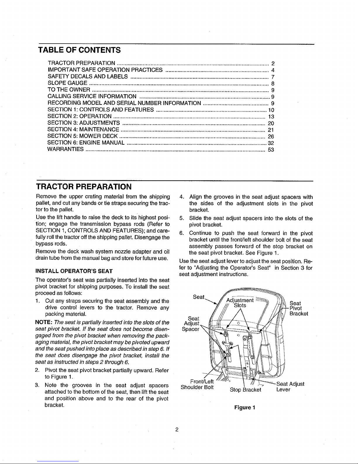
TABLE OF CONTENTS
TRACTOR PREPARATION .................................................................................................... 2
IMPORTANT SAFE OPERATION PRACTICES .................................................................... 4
SAFETY DECALS AND LABELS ........................................................................................... 7
SLOPE GAUGE ...................................................................................................................... 8
TO THE OWNER .................................................................................................................... 9
CALLING SERVICE INFORMATION ...................................................................................... 9
RECORDING MODEL AND SERIAL NUMBER INFORMATION ........................................... 9
SECTION 1: CONTROLS AND FEATURES ......................................................................... 10
SECTION 2: OPERATION .................................................................................................... 13
SECTION 3: ADJUSTMENTS .............................................................................................. 20
SECTION 4: MAINTENANCE ............................................................................................... 21
SECTION 5: MOWER DECK ................................................................................................ 26
SECTION 6: ENGINE MANUAL ............................................................................................ 32
WARRANTIES ...................................................................................................................... 53
TRACTOR PREPARATION
Remove the upper crating material from the shipping
pallet, and cut any bands or tie straps securing the trac-
tor to the pallet.
Use the lift handle to raise the deck to its highest posi-
tion; engage the transmission bypass rods (Refer to
SECTION 1, CONTROLS AND FEATURES); and care-
fully roll the tractor off the shipping pallet. Disengage the
bypass rods.
Remove the deck wash system nozzle adapter and oil
drain tube from the manual bag and store for future use.
INSTALL OPERATOR'S SEAT
The operator's seat was partially inserted into the seat
pivot bracket for shipping purposes. To install the seat
proceed as follows:
1. Cut any straps securing the seat assembly and the
drive control levers to the tractor. Remove any
packing material.
NOTE: The seat is partially inserted into the slots of the
seat pivot bracket. If the seat does not become disen-
gaged from the pivot bracket when removing the pack-
aging material the pivot bracket may be pivoted upward
and the seat pushed into place as described in step 6. If
the seat does disengage the pivot bracket, instal the
seat as instructed in steps 2 through 6.
2. Pivot the seat pivot bracket partially upward. Refer
to Figure 1.
3. Note the grooves in the seat adjust spacers
attached to the bottom of the seat, then lift the seat
and position above and to the rear of the pivot
bracket.
4. Align the grooves in the seat adjust spacers with
the sides of the adjustment slots in the pivot
bracket.
5. Slide the seat adjust spacers into the slots of the
pivot bracket.
6. Continue to push the seat forward in the pivot
bracket until the front/left shoulder bolt of the seat
assembly passes forward of the stop bracket on
the seat pivot bracket. See Figure 1.
Use the seat adjust lever to adjust the seat position. Re-
fer to "Adjusting the Operator's Seat" in Section 3 for
seat adjustment instructions.
Seat
Seat
Adjust_
Spacer ",_
Seat
Bracket
Front/Left ust
Shoulder Bolt Stop Bracket Lever
Figure 1
Page 3
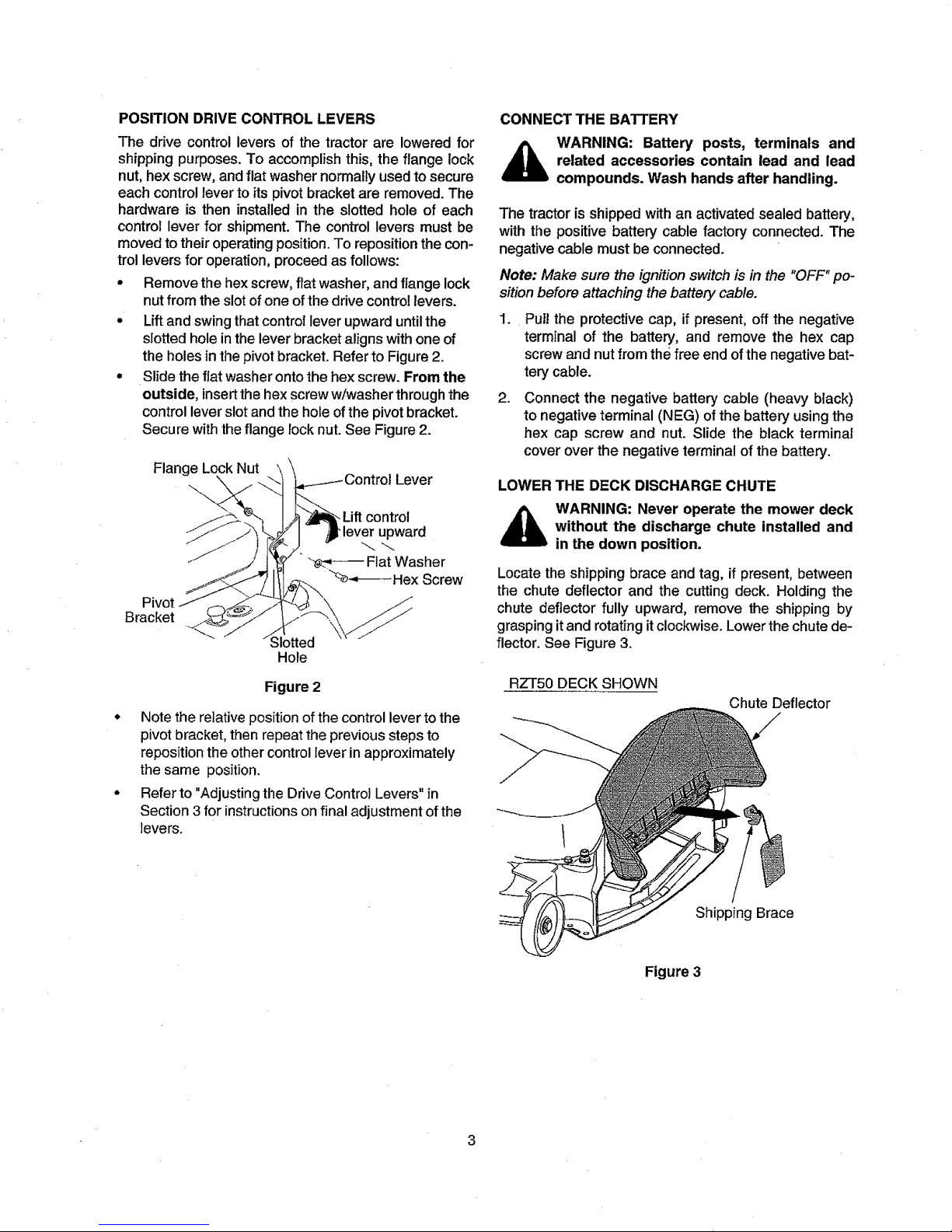
POSITION DRIVE CONTROL LEVERS
The ddve control levers of the tractor are lowered for
shipping purposes. To accomplish this, the flange lock
nut, hex screw, and flat washer normally usedto secure
each control lever to its pivot bracket are removed. The
hardware is then installedin the slotted hole of each
control lever for shipment. The control levers must be
moved to their operating position. To reposition the con-
trol levers for operation, proceed as follows:
- Remove the hex screw, flat washer, and flange lock
nutfrom the slot of one of the drive control levers.
- Lift and swing that controt lever upward until the
slotted hole in the lever bracket aligns with one of
the holes in the pivot bracket. Refer to Figure 2.
• Slide the fiat washer onto the hex screw. From the
outside, insertthe hex screw w/washer through the
control lever slot and the hole ofthe pivot bracket.
Secure with the flange rock nut. See Figure 2.
Flange Lock Nut
\ Lever
.Liftcontrol
upward
Fiat Washer
"x_*_--Hex Screw
Bracket
Slotted
Hole
Figure 2
° Note the relative position of the control lever to the
pivot bracket, then repeat the previous steps to
reposition the other control fever in approximately
the same position.
° Refer to "Adjusting the Drive Control Levers" in
Section 3 for instructions on final adjustment of the
levers.
CONNECT THE BATTERY
WARNING: Battery posts, terminals and
related accessories contain lead and lead
compounds. Wash hands after handling.
The tractor is shipped with an activated sealed battery,
with the positive battery cable factory connected. The
negative cable must be connected.
Note: Make sure the ignition switch is in the "OFF" po-
sition before attaching the battery cable.
.
,
Pull the protective cap, if present, off the negative
terminal of the battery, and remove the hex cap
screw and nut from the free end ofthe negative bat-
terycable.
Connect the negative battery cable (heavy black)
to negative terminal (NEG) of the battery using the
hex cap screw and nut. Slide the black terminal
cover over the negative terminal of the battery.
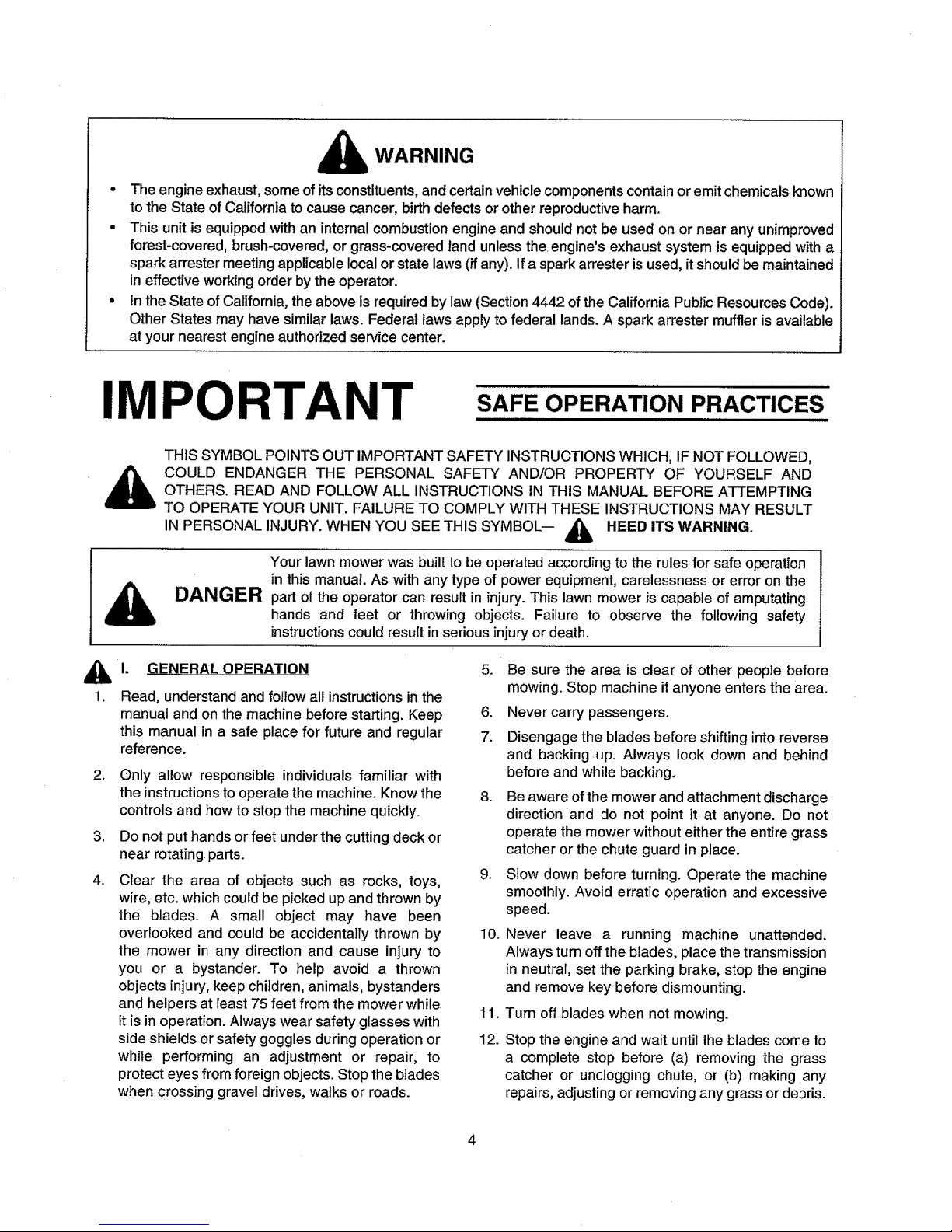
LOWER THE DECK DISCHARGE CHUTE
WARNING: Never operate the mower deck
without the discharge chute installed and
in the down position,
Locate the shipping brace and tag, if present, between
the chute deflector and the cutting deck. Holding the
chute deflector fully upward, remove the shipping by
grasping it and rotating it clockwise. Lower the chute de-
flector. See Figure 3.
RZT50 DECK SHOWN
Chute Deflector
Shipping Brace
Figure 3
3
Page 4
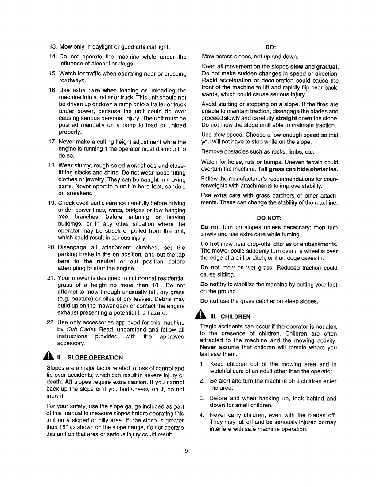
WARNING
• The engine exhaust, some of its constituents,andcertain vehicle components contain oremit chemicals known
to the State of California to cause cancer, birth defects or other reproductive harm.
° This unit is equipped with an internal combustion engine and should not be used on or near any unimproved
forest-covered, brush-covered, or grass-covered land unless the engine's exhaust system is equipped with a
spark arrester meeting applicable local or state laws (if any). If a spark arrester is used, it should be maintained
in effective working order by the operator.
• in the State of California, the above is required by law (Section 4442 of the California Public Resources Code),
Other States may have similar laws, Federal laws apply to federal lands. A spark arrester muffler is available
at your nearest engine authorized service center.
IMPORTANT
SAFE OPERATION PRACTICES
THIS SYMBOL POINTS OUT IMPORTANT SAFETY INSTRUCTIONS WHICH, IF NOT FOLLOWED,
COULD ENDANGER THE PERSONAL SAFETY AND/OR PROPERTY OF YOURSELF AND
OTHERS. READ AND FOLLOW ALL INSTRUCTIONS IN THIS MANUAL BEFORE ATTEMPTING
TO OPERATE YOUR UNIT. FAILURE TO COMPLY WITH THESE INSTRUCTIONS MAY RESULT
IN PERSONAL INJURY. WHEN YOU SEE THIS SYMBOL-- A_. HEED ITS WARNING.
Your lawn mower was built to be operated according to the rules for safe operation
in this manual, As with any type of power equipment, carelessness or error on the
DANGER part of the operator can result in injury.This lawn mower is capable of amputating
hands and feet or throwing objects. Failure to observe the following safety
instructions could result in serious injury or death.
1. GENERAL OPERATION
1. Read, understand and follow all instructions in the
manual and on the machine before starting. Keep
this manual in a safe place for future and regular
reference.
2.
,
4.
Only allow responsible individuals familiar with
the instructionsto operate the machine. Know the
controls and how to stop the machine quickly.
Do not put hands or feet under the cutting deck or
near rotatingparts.
Clear the area of objects such as rocks, toys,
wire, etc. which could be picked up and thrown by
the blades. A small object may have been
overlooked and could be accidentally thrown by
the mower in any direction and cause injury to
you or a bystander. To help avoid a thrown
objects injury, keep children, animals, bystanders
and helpers at least 75 feet from the mower while
it is in operation. Always wear safety glasses with
side shields or safety goggles during operation or
while performing an adjustment or repair, to
protect eyes from foreign objects. Stop the blades
when crossing gravel drives, walks or roads.
5. Be sure the area is clear of other people before
mowing. Stop machine if anyone enters the area.
6. Never carry passengers.
7. Disengage the blades before shifting into reverse
and backing up. Always look down and behind
before and while backing.
8. Be aware of the mower and attachment discharge
direction and do not point it at anyone. Do not
operate the mower without either the entire grass
catcher or the chute guard in place.
9. Slow down before turning. Operate the machine
smoothly. Avoid erratic operation and excessive
speed.
I0. Never leave a running machine unattended.
Always turn off the blades, place the transmission
in neutral, set the parking brake, stop the engine
and remove key before dismounting.
11.
12.
Turn off blades when not mowing.
Stop the engine and wait until the blades come to
a complete stop before (a) removing the grass
catcher or unclogging chute, or (b) making any
repairs, adjusting or removing any grass or debris.
4
Page 5
13. Mow only in daylight or good artificial light.
14. Do not operate the machine while under the
influence of alcohol or drugs.
15. Watch for traffic when operating near or crossing
roadways.
16. Use extra care when loading or unloading the
machine into a trailer or truck. This unit should not
be driven up or down a ramp onto a trailer or truck
under power, because the unit could tip over
causing serious personal injury. The unit must be
pushed manually on a ramp to load or unload
properly.
17. Never make a cutting height adjustment while the
engine is running if the operator must dismount to
do so.
18.
Wear sturdy, rough-soled work shoes and close-
fitting slacks and shirts. Do not wear loose fitting
clothes or jewelry. They can be caught in moving
parts. Never operate a unit in bare feet, sandals
or sneakers.
!9. Check overhead clearance carefully before driving
under power lines, wires, bridges or low hanging
tree branches, before entering or leaving
buildings, or in any other situation where the
operator may be struck or putled from the unit,
which could result in serious injury.
20. Disengage all attachment clutches, set the
parking brake in the on position, and put the tap
bars to the neutral or out position before
attempting to start the engine.
21. Your mower is designed to cut normal residential
grass of a height no more than 10". Do not
attempt to mow through unusually tall, dry grass
(e.g. pasture) or piles of dry leaves. Debris may
build up on the mower deck or contact the engine
exhaust presenting a potential fire hazard.
22. Use only accessories approved for this machine
by Cub Cadet. Read, understand and follow all
instructions provided with the approved
accessory.
_11. SLOPE OPERATIQN
Slopes are a major factor related to loss of control and
tip-over accidents, which can result in severe injury or
death. All slopes require extra caution. If you cannot
back up the slope or if you feel uneasy on it, do not
mow it.
For your safety, use the slope gauge included as part
of this manual to measure slopes before operating this
unit on a sloped or hilly area. If the slope is greater
than I5 ° as shown on the slope gauge, do not operate
this unit on that area or serious injury could result.
DO:
Mow across slopes, not up and down.
Keep all movement on the slopes slow and gradual.
Do not make sudden changes in speed or direction.
Rapid acceleration or deceleration could cause the
front of the machine to lift and rapidly flip over back-
wards, which could cause serious injury.
Avoid starting or stopping on a slope. If the tires are
unable to maintain traction, disengage the blades and
proceed slowly and carefully straight down the slope.
Do not mow the slope until able to maintain traction.
Use slow speed. Choose a low enough speed so that
you will not have to stop while on the slope.
Remove obstacles such as rocks, limbs, etc.
Watch for holes, ruts or bumps. Uneven terrain could
overturn the machine. Tall grass can hide obstacles.
Follow the manufacturer's recommendations for coun-
terweights with attachments to improve stability.
Use extra care with grass catchers or other attach-
ments. These can change the stability of the machine.
DO NOT:
Do not turn on slopes unless necessary; then turn
slowly and use extra care while turning.
Do not mow near drop-offs, ditches or embankments.
The mower could suddenly turn over if a wheel is over
the edge of a cliff or ditch, or if an edge caves in.
Do not mow on wet grass. Reduced traction could
cause sliding.
Do not try to stabilize the machine by putting your foot
on the ground.
Do not use the grass catcher on steep slopes.
III. CHILDREN
Tragic accidents can occur if the operator is not alert
to the presence of children. Children are often
attracted to the machine and the mowing activity.
Never assume that children will remain where you
last saw them.
1. Keep children out of the mowing area and in
watchful care of an adult other than the operator.
2. Be alert and turn the machine off if children enter
the area.
3.
4.
Before and when backing up, took behind and
down for small children.
Never carry children, even with the blades off.
They may fall off and be seriously injured or may
interfere with safe machine operation.
Page 6
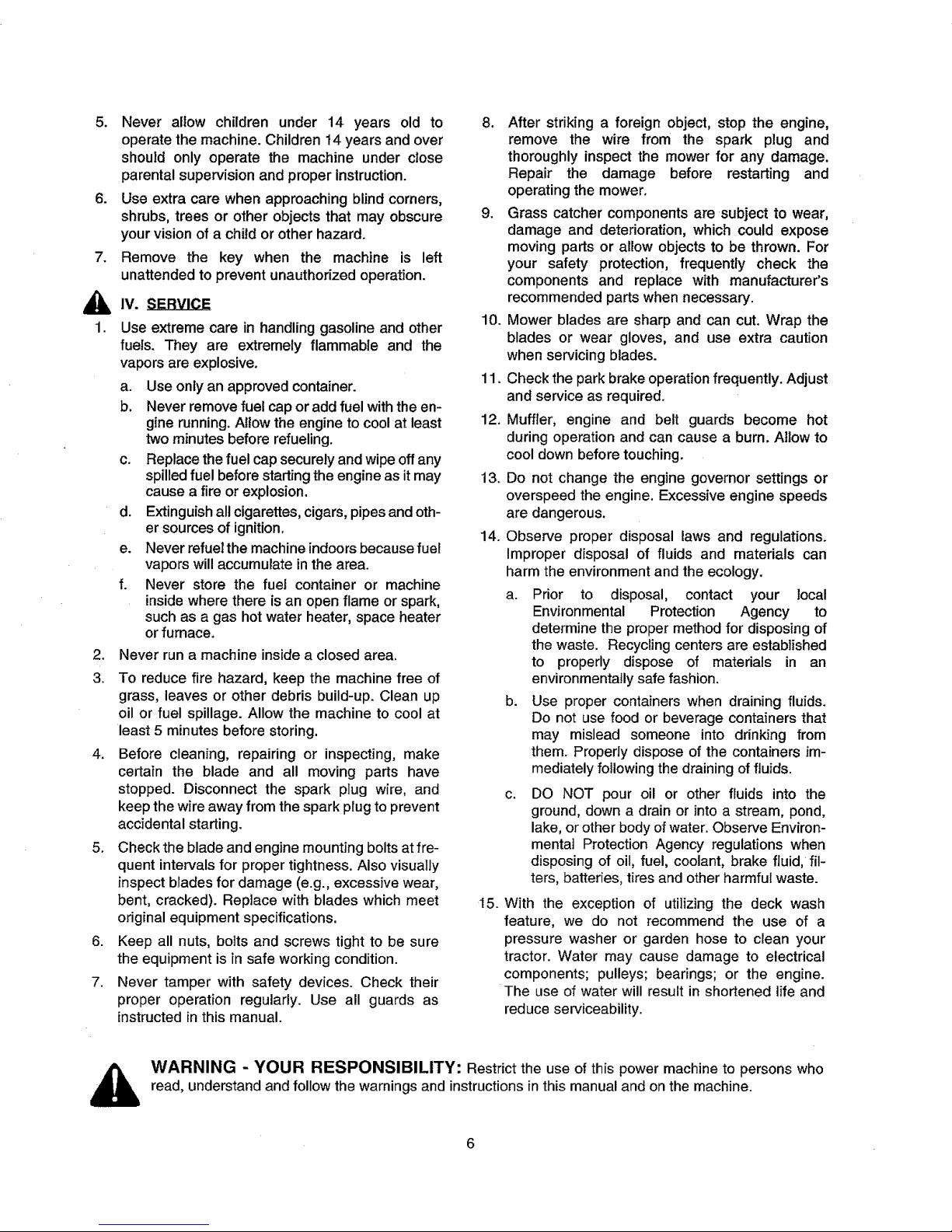
5. Never allow children under 14 years old to
operate the machine. Children 14 years and over
should only operate the machine under close
parental supervision and proper instruction.
6. Use extra care when approaching blind corners,
shrubs, trees or other objects that may obscure
your vision of a child or other hazard.
7. Remove the key when the machine is left
unattended to prevent unauthorized operation.
1.
3.
IV. SERVICE
Use extreme care in handlinggasoline and other
fuels. They are extremely flammable and the
vapors are explosive.
a. Use only an approved container.
b. Never remove fuel cap or add fuel with the en-
gine running. Allow the engine to cool at least
two minutes before refueling.
c. Replace the fuel cap securely and wipe off any
spilled fuel before starting the engine as it may
cause a fire or explosion.
d. Extinguish all cigarettes, cigars, pipes and oth-
er sources of ignition.
e. Never refuel the machine indoors because fuel
vapors will accumulate in the area.
f. Never store the fuel container or machine
inside where there is an open flame or spark,
such as a gas hot water heater, space heater
or furnace.
Never run a machine inside a closed area.
To reduce fire hazard, keep the machine free of
grass, leaves or other debris build-up. Clean up
oil or fuel spillage. Allow the machine to cool at
least 5 minutes before storing.
4. Before cleaning, repairing or inspecting, make
certain the blade and all moving parts have
stopped. Disconnect the spark plug wire, and
keep the wire away from the spark ptug to prevent
accidental starting.
5. Check the blade and engine mounting bolts at fre-
quent intervals for proper tightness. Also visually
inspect blades for damage (e.g., excessive wear,
bent, cracked). Replace with blades which meet
original equipment specifications.
6. Keep all nuts, bolts and screws tight to be sure
the equipment is in safe working condition.
7. Never tamper with safety devices. Check their
proper operation regularly. Use all guards as
instructed in this manual.
8. After striking a foreign object, stop the engine,
remove the wire from the spark plug and
thoroughly inspect the mower for any damage.
Repair the damage before restarting and
operating the mower.
9. Grass catcher components are subject to wear,
damage and deterioration, which could expose
moving parts or altow objects to be thrown. For
your safety protection, frequently check the
components and replace with manufacturer's
recommended parts when necessary.
10. Mower blades are sharp and can cut. Wrap the
blades or wear gloves, and use extra caution
when servicing blades.
11. Check the park brake operation frequently. Adjust
and service as required.
12+Muffler, engine and belt guards become hot
during operation and can cause a burn. Allow to
cool down before touching.
13. Do not change the engine governor settings or
overspeed the engine. Excessive engine speeds
are dangerous.
14. Observe proper disposal laws and regulations.
Improper disposal of fluids and materials can
harm the environment and the ecology.
a. Prior to disposal, contact your local
Environmental Protection Agency to
determine the proper method for disposing of
the waste. Recycling centers are established
to properly dispose of materials in an
environmentally safe fashion.
b. Use proper containers when draining fluids.
Do not use food or beverage containers that
may mislead someone into drinking from
them. Properly dispose of the containers im-
mediately following the draining of fluids.
C.
DO NOT pour oil or other fluids into the
ground, down a drain or into a stream, pond,
lake, or other body of water. Observe Environ-
menta] Protection Agency regulations when
disposing of oil, fuel, coolant, brake fluid, fil-
ters, batteries, tires and other harmful waste.
15. With the exception of utilizing the deck wash
feature, we do not recommend the use of a
pressure washer or garden hose to clean your
tractor. Water may cause damage to electrical
components; pulleys; bearings; or the engine.
The use of water will result in shortened life and
reduce serviceability.
_lb WARNING - YOUR RESPONSIBILITY: Restrict the use of this power machine to persons who
read, understand and follow the warnings and instructions in this manual and on the machine.
Page 7
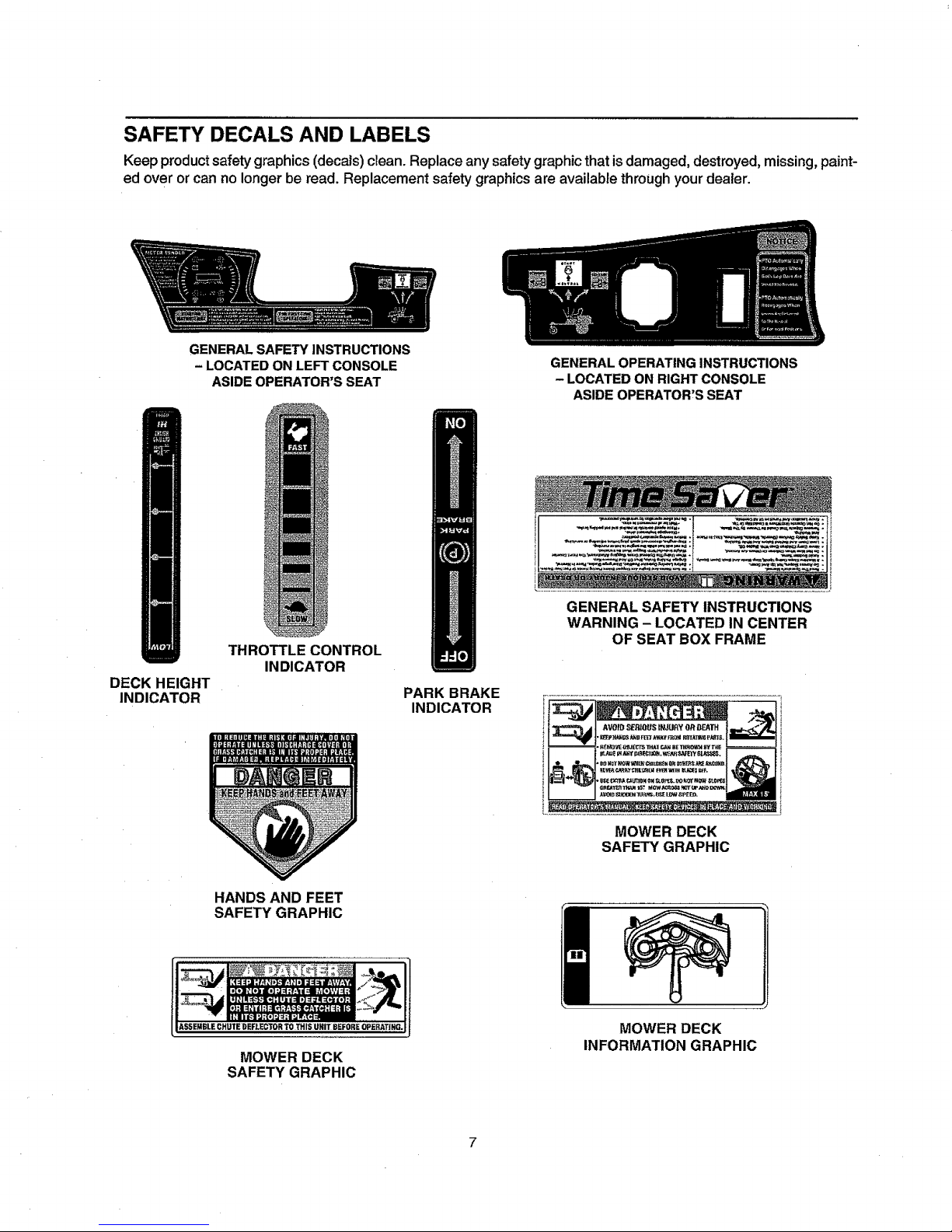
SAFETY DECALS AND LABELS
Keep product safety graphics (decals) clean. Replace any safety graphic that is damaged, destroyed, missing, paint-
ed over or can no longer be read. Replacement safety graphics are available through your dealer.
GENERAL SAFETY INSTRUCTIONS
- LOCATED ON LEFT CONSOLE
ASIDE OPERATOR'S SEAT
GENERAL OPERATING INSTRUCTIONS
- LOCATED ON RIGHT CONSOLE
ASIDE OPERATOR'S SEAT
DECK HEIGHT
INDICATOR
THROTTLE CONTROL
INDICATOR
PARK BRAKE
INDICATOR
i j
GENERAL SAFETY INSTRUCTIONS
WARNING - LOCATED IN CENTER
OF SEAT BOX FRAME
MOWER DECK
SAFETY GRAPHIC
HANDS AND FEET
SAFETY GRAPHIC
ASSEMBLE CHUTE DEFLECTOR TO THISIUNITI BEFORE OPERATING.
MOWER DECK
SAFETY GRAPHIC
MOWER DECK
INFORMATION GRAPHIC
Page 8

USE THIS PAGE AS A GUIDE TO DETERMINE SLOPES WHERE YOU MAY NOT OPERATE SAFELY.
-.,d
I
Co
I
SIGHT AND HOLD THIS LEVEL WITH A VERTICAL TREE
A POWER POLE
I _" A CORNER OF A BUILDING
| = .
| --... OR A FENCE POST
I
I _ ~ ~ u LIN,_ ,,,
..
I
I
15 °
WARNING
Do not mow on inclines with a slope in excess of 15 degrees (a rise of approximately 2-1/2 feet every 10 feet).
A riding mower could overturn and cause serious injury. ]f operating a walk-behind mower on such a slope, it is
extremely difficult to maintain your footing and you could slip, resulting in serious injury.
Operate RZT zero turn tractors across the face of slopes rather than up and down. Begin with the first pass
across the bottom of the slope and turn uphill at the end of each pass whenever possible.
=rrl
:3
P
v
Page 9
TO THE OWNER
This Operator's Manual is an importantpartof your newtractor.The informationcontained in thismanual has been
prepared in detail to help you better understand the features, correct operation, adjustments, and maintenance of
your tractor. The performance and dependability of this tractor rely greatly on the manner inwhich itis operated and
maintained. Therefore, it is recommended that all operators of the tractor carefully read this manual and fully under-
stand its operation. Also keep the manual available for reference to ensure proper operation, and that maintenance
procedures are performed as scheduled to assure the tractor's optimal mechanical condition.
NOTE: All references to LEFT, RIGHT, FRONT, and REAR, unless specifically stated otherwise, indicate that rela-
tive position on the tractor when facing forward while seated in the operator's seat.
CAUTION: DO NOT tow your RZT model tractor. Towing may damage the transmissions. Place the tractor on a
LEVEL SURFACE before pulling the transmission bypass rods to the engaged position (transmission disengaged).
Your localauthorized Cub Cadet dealer is interested in the performance you receive from your tractor, and with the
maintenance needed to ensure the satisfactory operation of your tractor. The dealer has trained service personnel
familiar with the latest servicing information, is equipped with the latest tools, and has a complete line of genuine
Cub Cadet service parts which assure properfit and high quality.
CALLING SERVICE INFORMATION
The engine manufacturer isresponsible for all engine-related issueswithregards to performance, power-rating, and
specifications.
Ifyou have difficulties with the tractor and/or equipment; have any questions regarding the operation or maintenance
of this equipment; or desire additional information not found in this manual, contact your nearest authorized Cub
Cadet dealer. If you need assistance in locating a dealer in your area, contact the Customer Dealer ReferralLine by
calling:
1-877-282-8684
Or you may contact Cub Cadet via the internet by logging on to our Web Site at:
www.cubcadet.com
To obtain top performance and assure economical operation, the tractor should be inspected by your authorized
dealer periodically or at least once a year, depending on its hours of use. Before calling your dealer, make sure that
you have your model number(s) and manufacturing date available for the dealer,
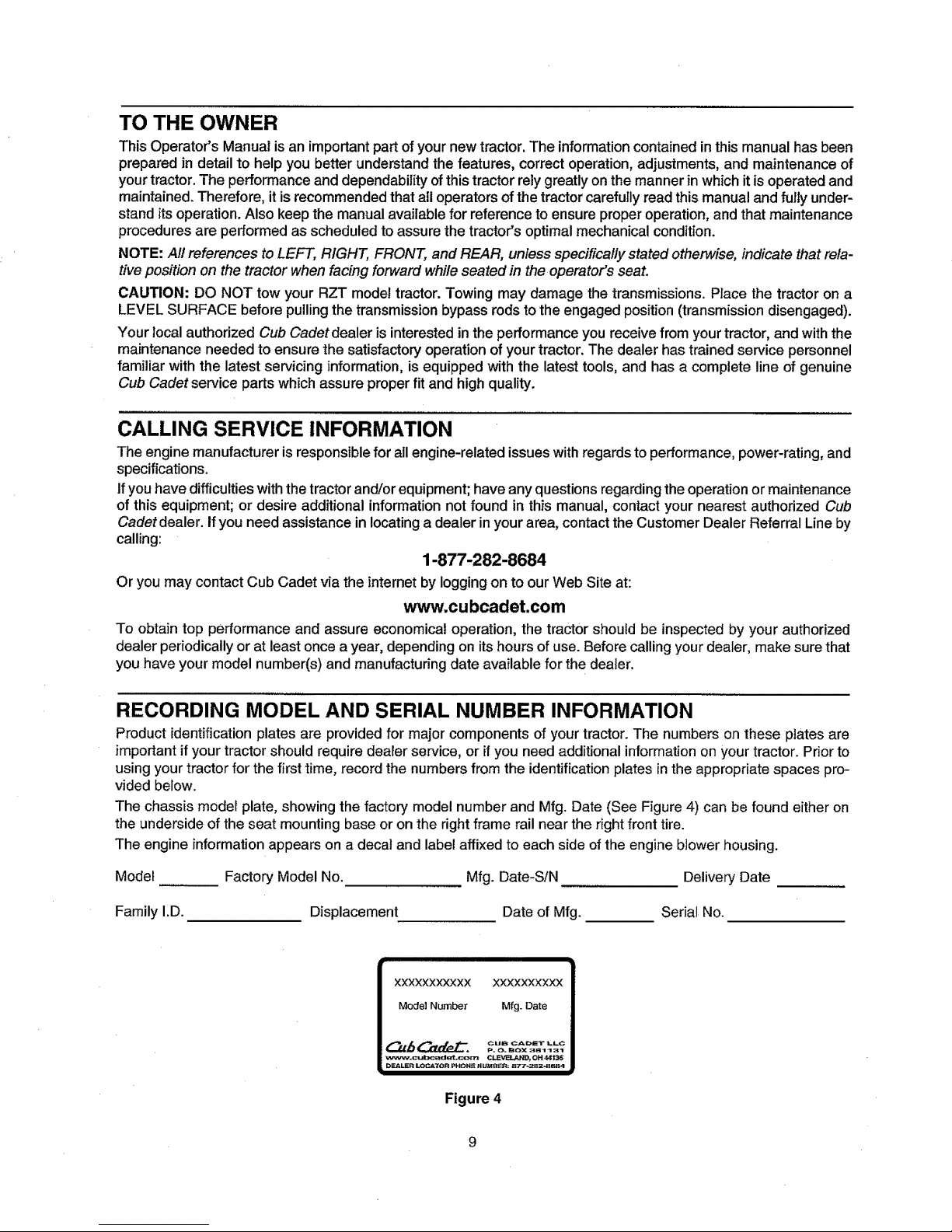
RECORDING MODEL AND SERIAL NUMBER INFORMATION
Product identification plates are provided for major components of yourtractor.The numbers on these plates are
important if your tractor should require dealer service, or ifyou need additional information on your tractor. Prior to
using your tractor for the first time, record the numbers from the identification plates in the appropriate spaces pro-
vided below.
The chassis model plate, showing the factory model number and Mfg. Date (See Figure 4) can be found either on
the underside of the seat mounting base or onthe right frame rail near the right front tire.
The engine information appears on a decal and label affixed to each side of the engine blower housing.
Model Factory Model No. Mfg. Date-S/N Delivery Date
Family I.D. Displacement Date of Mfg. Serial No.
i
XXXXXXXXXXX XXXXXXXXXX
Model Number Mfg. Date
P. O. BOX 31_1131
_Nw.cul_adst cm _, OH 4_1_
>gJ_LER LOC_70R PHON_ N UMS_J_: _77-2BZ_B_B4
i i
Figure 4
Page 10
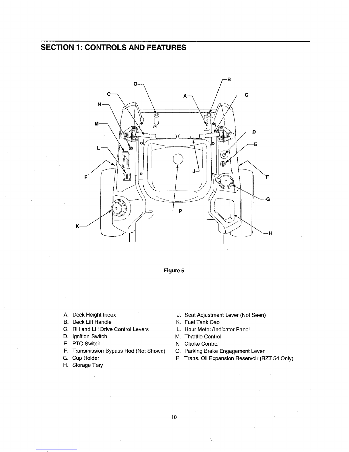
SECTION 1: CONTROLS AND FEATURES
P
/
Figure 5
A. Deck Height Index
B. Deck Lift Handle
C. RH and LH Drive Control Levers
D. Ignition Switch
E. PTO Switch
F. Transmission Bypass Rod (Not Shown)
G. Cup Holder
H. Storage Tray
J. Seat Adjustment Lever (Not Seen)
K. Fuel Tank Cap
L. Hour Meter/Indicator Panel
M. Throttle Control
N. Choke Control
O. Parking Brake Engagement Lever
P. Trans. Oil Expansion Reservoir (RZT 54 Only)
10
Page 11
NOTE: References to LEFT, RIGHT, FRONT, and
REAR indicate that position on the tractor when
facing forward while seated in the operators seat.
A. Deck Height Index
The deck height index consists of six index notches
located on the front/right of the seat box frame. Each
notch corresponds to a 1/2 inch change in the deck
height position ranging from 1-1/2 inches at the low-
est notch to 4 inches at the highest notch.
B. Deck Lift Handle
The deck lift handle is located on the front/right of the
seat box frame, and is used to raise and lower the
mower deck.
Pull the handle to the left out of the index notch and
push downward to lower the deck, or pull upward to
raise the deck. When the desired height is attained,
move the lift handle to the right until fully in the index
notch.
C. RH and LH Drive Control Levers
The RH and LH control levers are located on each
side of the operator'sseat. These hingedlevers pivot
outwardtoopenspace to permitthe operatorto either
sit in the tractor seat, or to dismountthe tractor. The
levers must be fully opened out and in the neutral
positionto start the tractorengine.
Each levercontrolsthe respective RH or LHtransmis-
sion. Consequently, these levers control all of the
movements of the tractor. Driving and steering utiliz-
ing these control levers is quite different from
conventionaltractors,and willtake some practice to
master. Refer to SECTION 2: OPERATION for
instructionson usingthe control levers.
D. Ignition Switch
The ignitionswitch is located on the RH console to
the right ofthe operator'sseat.
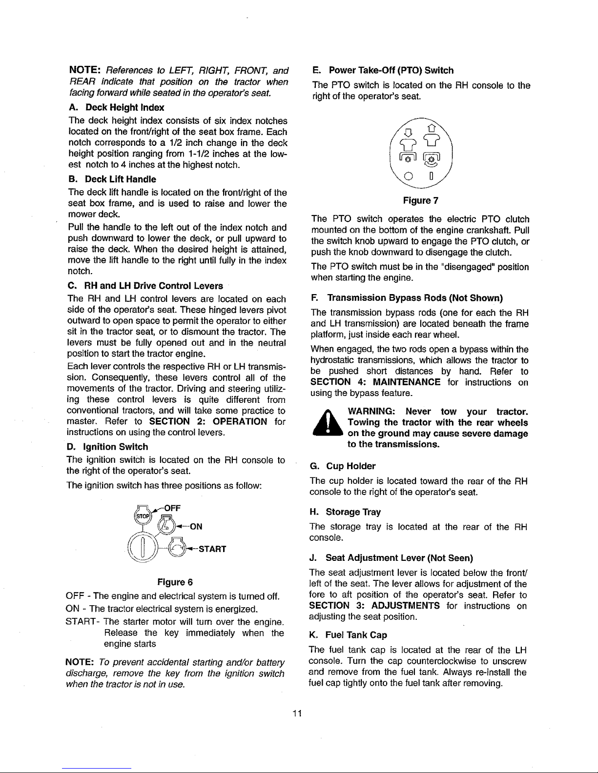
The ignitionswitch has three positions as follow:
OFF
ON
START
Figure 6
OFF - The engine and electrical system is turned off.
ON - The tractor electrical system is energized.
START- The starter motor will turn over the engine.
Release the key immediately when the
engine starts
NOTE: To prevent accidental starting and/or battery
discharge, remove the key from the ignition switch
when the tractor is not in use.
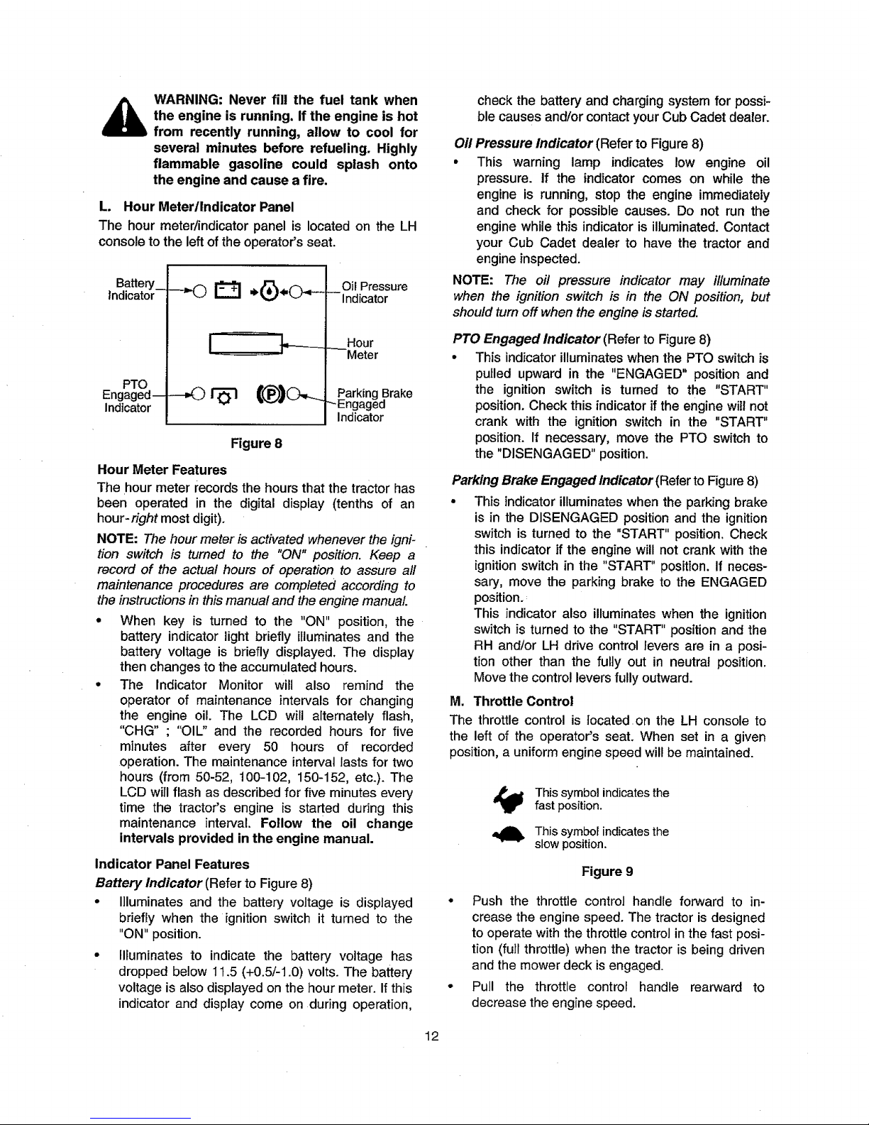
E. Power Take-Off (PTO) Switch
The PTO switch is located on the RH console to the
rightofthe operator'sseat.
Figure 7
The PTO switch operates the electric PTO clutch
mounted on the bottom of the engine crankshaft. Pull
the switch knob upward to engage the PTO clutch, or
push the knob downward to disengage the clutch.
The PTO switch must be in the "disengaged" position
when starting the engine.
R Transmission Bypass Rods (Not Shown)
The transmission bypass rods (one for each the RH
and LH transmission) are located beneath the frame
platform, just insideeach rear wheel.
When engaged, the two rods open a bypass within the
hydrostatic transmissions, which allows the tractor to
be pushed short distances by hand. Refer to
SECTION 4: MAINTENANCE for instructions on
using the bypass feature.
WARNING: Never tow your tractor.
Towing the tractor with the rear wheels
on the ground may cause severe damage
to the transmissions.
G. Cup Holder
The cup holder is located toward the rear of the RH
console to the right of the operator's seat.
H. Storage Tray
The storage tray is located at the rear of the RH
consoJe.
J. Seat Adjustment Lever (Not Seen)
The seat adjustment lever is located below the front/
left of the seat. The lever allows for adjustment of the
fore to aft position of the operator's seat. Refer to
SECTION 3: ADJUSTMENTS for instructions on
adjusting the seat position.
K. Fuel Tank Cap
The fuel tank cap is tocated at the rear of the LH
console. Turn the cap counterclockwise to unscrew
and remove from the fuel tank. Always re-install the
fuel cap tightly onto the fuel tank after removing.
11
Page 12
WARNING: Never fill the fuel tank when
the engine is running. If the engine is hot
from recently running, allow to cool for
several minutes before refueling. Highly
flammable gasoline could splash onto
the engine and cause a fire.
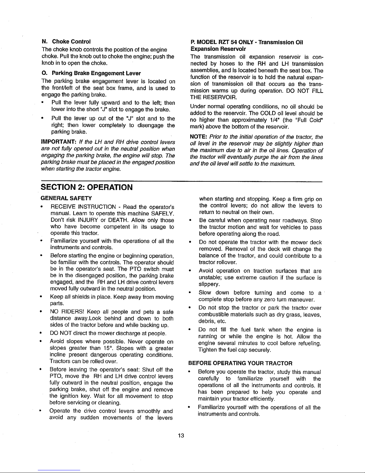
L. Hour Meter/Indicator Panel
The hour meter/indicator panel is located on the LH
consoleto the left of the operator'sseat.
Battery_
indicator
PTO
Engaged--
Indicator
Oil Pressure
Indicator
Hour
_Meter
Parking Brake
_Engaged
Indicator
Figure 8
Hour Meter Features
The hour meter records the hours that the tractor has
been operated in the digital display (tenths of an
hour-right most digit).
NOTE: The hour meter is activated whenever the igni-
tion switch is turned to the "ON" position. Keep a
record of the actual hours of operation to assure all
maintenance procedures are completed according to
the instructions in this manual and the engine manual
• When key is turned to the "ON" position, the
battery indicator light briefly illuminates and the
battery voltage is briefly displayed. The display
then changes to the accumulated hours.
• The Indicator Monitor will also remind the
operator of maintenance intervals for changing
the engine oil. The LCD will alternately flash,
"CHG" ; "OIL" and the recorded hours for five
minutes after every 50 hours of recorded
operation. The maintenance interval lasts for two
hours (from 50-52, 100-102, 150-152, etc.). The
LCD will flash as described for five minutes every
time the tractor's engine is started during this
maintenance interval. Follow the oil change
intervals provided in the engine manual.
Indicator Panel Features
Battery Indicator (Refer to Figure 8)
• Illuminatesand the battery voltage is displayed
briefly when the ignition switch it turned to the
"ON" position.
• Illuminates to indicate the battery voltage has
dropped below 11.5 (+0.5/-1.0) volts. The battery
voltageis also displayed on thehour meter. Ifthis
indicator and display come on during operation,
check the battery and charging system for possi-
ble causes and/orcontact your Cub Cadet dealer.
Oil Pressure Indicator (Refer to Figure 8)
° This warning lamp indicates low engine oil
pressure. If the indicator comes on while the
engine is running, stop the engine immediately
and check for possible causes. Do not run the
engine while this indicatoris illuminated.Contact
your Cub Cadet dealer to have the tractor and
engine inspected.
NOTE: The oil pressure indicator may illuminate
when the ignition switch is in the ON position, but
should turn off when the engine is started.
PTO Engaged Indicator (Refer to Figure 8)
• This indicatorilluminates when the PTO switch is
pulled upward in the "ENGAGED" positionand
the ignition switch is turned to the "START"
position. Check this indicator if the enginewillnot
crank with the ignition switch in the "START"
position.If necessary, move the PTO switch to
the "DISENGAGED" position.
Parking Brake Engaged Indicator (Refer to Figure 8)
• This indicatorilluminateswhen the parkingbrake
is in the DISENGAGED positionand the ignition
switch is turned to the "START" position, Check
this indicatorif the engine willnot crank withthe
ignition switch in the "START" position. If neces-
sary, move the parking brake to the ENGAGED
position._
This indicator also illuminateswhen the ignition
switch }s turned to the "START" position and the
RH and/or LH drive controllevers are in a posi-
tion other than the fully out in neutral position.
Movethe controlleversfullyoutward.
M. Throttle Control
The throttle control is located on the LH console to
the left of the operator's seat. When set in a given
position, a uniform engine speed will be maintained.
This symbol indicatesthe
fast position.
This symbol indicates the
slow position.
Figure 9
• Push the throttle control handle forward to in-
crease the engine speed. The tractor is designed
to operate with the throttle control in the fast posi-
tion (full throttle) when the tractor is being driven
and the mower deck is engaged.
• Pull the throttle controf handle rearward to
decrease the engine speed.
12
Page 13
N. Choke Control
The choke knobcontrolsthe positionof the engine
choke.Pulltheknobouttochoke the engine; pushthe
knobinto open the choke.
O. Parking Brake Engagement Lever
The parking brake engagement lever is located on
the front/left of the seat box frame, and is used to
engage the parkingbrake.
• Pull the lever fully upward and to the left; then
lowerintothe short "J" slot toengage the brake.
• Pul! the lever up out of the "J" slot and to the
right; then lower completely to disengage the
parkingbrake.
IMPORTANT: If the LH and RH drive control levers
are not fully opened out in the neutral position when
engaging the parking brake, the engine will stop. The
parking brake must be placed in the engaged position
when starting the tractor engine.
P.MODEL RZT 54 ONLY - Transmission Oil
Expansion Reservoir
The transmission oil expansion reservoir is con-
nected by hoses to the RH and LH transmission
assemblies, and is located beneath the seat box. The
function of the reservoir is to hold the natural expan-
sion of transmission oil that occurs as the trans-
mission warms up during operation. DO NOT FILL
THE RESERVOIR.
Under normal operating conditions, no oil should be
added to the reservoir. The COLD oil level shoufd be
no higher than approximately 1/4" (the "Full Cold"
mark) above the bottom of the reservoir.
NOTE: Prior to the initia! operationof the tractor, the
oil level in the reservoir may be slightly higher than
the maximum due to air in the oil lines. Operation of
the tractor will eventually purge the air fromthe fines
and the oil level will settle to themaximum.
SECTION 2: OPERATION
GENERAL SAFETY
• RECEIVE INSTRUCTION - Read the operator's
manual. Learn to operate this machine SAFELY.
Don't risk iNJURY or DEATH. Allow only those
who have become competent in its usage to
operate this tractor.
• Familiarize yourself with the operations of all the
instruments and controls.
• Before starting the engine or beginning operation,
be familiar with the controls. The operator should
be in the operator's seat. The PTO switch must
be in the disengaged position, the parking brake
engaged, and the RH and LH drive control levers
moved fully outward in the neutral position.
• Keep all shields in place. Keep away from moving
parts.
• NO RIDERS! Keep all people and pets a safe
distance away.Look behind and down to both
sides of the tractor before and while backing up.
• DO NOT direct the mower discharge at people.
• Avoid slopes where possible. Never operate on
slopes greater than 15°. Slopes with a greater
incline present dangerous operating conditions.
Tractors can be rolled over.
• Before leaving the operator's seat: Shut off the
PTO, move the RH and LH drive control levers
fully outward in the neutral position, engage the
parking brake, shut off the engine and remove
the ignition key. Wait for all movement to stop
before servicing or cleaning.
• Operate the drive control levers smoothly and
avoid any sudden movements of the levers
when starting and stopping. Keep a firm grip on
the control levers; do not allow the levers to
return to neutral on their own.
• Be careful when operating near roadways. Stop
the tractor motion and wait for vehicles to pass
before operating along the road.
• Do not operate the tractor with the mower deck
removed. Removal of the deck will change the
balance of the tractor, and could contribute to a
tractor rollover.
• Avoid operation on traction surfaces that are
unstable; use extreme caution if the surface is
slippery.
° Slow down before turning and come to a
complete stop before any zero turn maneuver.
• Do not stop the tractor or park the tractor over
combustible materials such as dry grass, leaves,
debris, etc.
• Do not fill the fuel tank when the engine is
running or while the engine is hot. Allow the
engine several minutes to cool before refueling.
Tighten the fuel cap securely.
BEFORE OPERATING YOUR TRACTOR
• Before you operate the tractor,study this manual
carefully to familiarize yourself with the
operationsof all the instruments and controls. It
has been prepared to help you operate and
maintain yourtractor efficiently.
• Familiarize yourself with the operationsof all the
instruments and controls.
13
Page 14
• This engine is certified to operate only on clean,
fresh, unleaded regular gasoline. For best results,
fill the fuel tank with only clean, fresh, unleaded
gasoline with a pump sticker octane rating of 87
or higher.
• Unleaded gasoline is recommended because it
leaves less combustion chamber deposits and
reduces harmful exhaust emissions. Leaded
gasoline is not recommended and must not be
used where exhaust emissions are regulated.
NOTE: Purchase gasoline in small quantities. Do not
use gasoline left over from the previous season, to
minimize gum deposits in the fuel system.
• Gasohol (up to 10% ethyl alcohol, 90% unleaded
gasoline by volume) is an approved fuel. Other
gasoline/alcohol blends are not approved.
• Methyl Tertiary Butyl Ether (MTBE) and unleaded
gasoline blends (up to a maximum of 15% MTBE
by volume) are approved fuels. Other gasoline/
ether blends are not approved.
• Check the engine oil level.
• Clean the air cleaner element if necessary.
• Check the tire inflation pressures.
• Adjust the seat for operator's maximum comfort,
visibility and for maintaining complete control of
the tractor.
SAFETY INTERLOCK SYSTEM
This tractor is equipped with a safety interlock system
for the protection of the operator. If the interlock
system should ever malfunction, do not operate the
tractor. Contact your authorized Cub Cadet Dealer.
• The safety interlock system prevents the engine
from cranking or starting unless the RH and LH
drive control levers are moved fully outward in the
neutral position, the parking brake is engaged,
and the PTO is disengaged.
• To avoid sudden movement when disengaging
the parking brake, the safety interlock system will
shut off the engine if the RH and/or LH drive
control levers are moved to a position other than
the fully out in neutral position when the parking
brake is engaged
• The safety interlock system will shut off the
engine if the operator leaves the seat before
engaging the parking brake.
• The safety interlock system will shut off the
engine if the operator leaves the seat with the
PTO engaged, regardless of whether the parking
brake is engaged.
NOTE: The PTO switch must be moved to the
"OFF" position to restart the engine.
The safety interlocksystem will shut off the PTO
and the mower blades will stop if both drive con-
trol levers are moved into the reverse position.
The PTO will re-engage when one or both of the
levers are moved back to the neutral or forward
position.
STARTING THE ENGINE
WARNING: This unit is equipped with a
safety interlock system designed for the
protection of the operator. Do not oper-
ate the tractor if any part of the interlock
system is malfunctioning. Periodically
check the functions of the interlock sys-
tem for proper operation.
_1 WARNING: For personal safety, the
operator must be sitting in the tractor
seat when starting the engine.
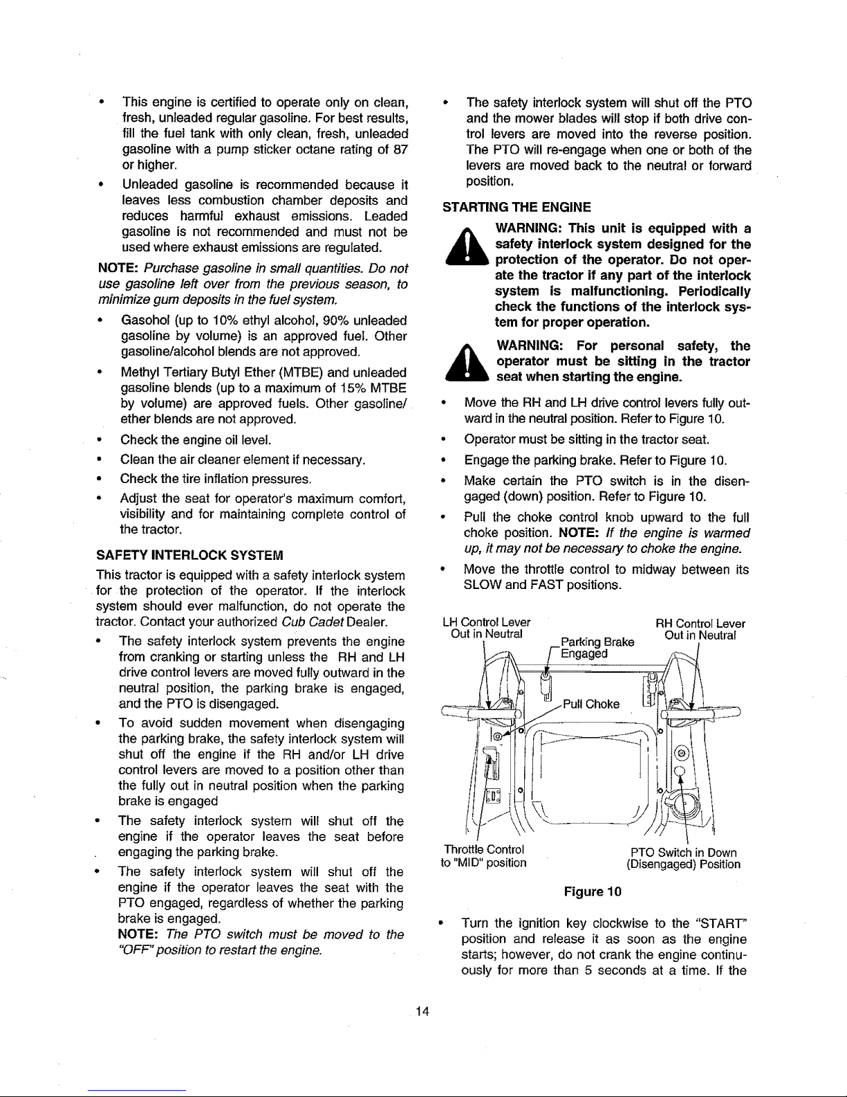
• Move the RH and LH drive control levers fully out-
ward in theneutral position. Refer to Figure10.
• Operator mustbe sittinginthe tractorseat.
• Engagethe parkingbrake. Refer to Figure 10.
• Make certain the PTO switch is in the disen-
gaged (down)position. Refer to Figure10.
• PuU the choke control knob upward to the full
choke position.NOTE: If the engine is warmed
up, it may not be necessary to choke the engine.
• Move the throttle controlto midway between its
SLOW and FAST positions.
LH Control Lever RH Control Lever
Out in Neutral Out in Neutrai
ParkingBrake
Engaged
oL
Throttle Control
to "MID" position
PTO Switch in Down
(Disengaged) Position
Figure 10
Turn the ignition key clockwise to the "START"
position and release it as soon as the engine
starts; however, do not crank the engine continu-
ously for more than 5 seconds at a time. If the
14
Page 15
engine does not start withinthis time, turn the key
to "OFF" and wait at least 15 seconds to allow the
engine's starter motor to cool. Try again after
waiting. If after a few attempts the engine fails to
start, do not keep trying to start it with the choke
dosed as this will cause flooding and make start-
ing more difficult.
As the engine warms up, gradually push the
choke knob downward to open the choke. Do not
use the choke to enrich the fuel mixture, except
as necessary to start the engine.
Allow the engine to run for a few minutes at mid
throttle before putting the engine under load.
Observe the hour meter/indicator panel. If the
battery indicator light or oil pressure light come
on, immediately stop the engine. Have the tractor
inspected by your Cub Cadet dealer.
COLD WEATHER STARTING
• When starting the engine at temperatures near or
below freezing, ensure the correct viscosity motor
oil is used in the engine and the battery is fully
charged. Start the engine as follows:
° Be sure the battery is in good condition. A warm
battery has much more starting capacity than a
cold battery.
• Use fresh winter grade fuel. Winter grade
gasoline has higher volatility to improve starting.
Do not use gasoline left over from summer.
• Follow the previous instruction for STARTING
THE ENGINE.
USING JUMPER CABLES TO START ENGINE
WARNING: Batteries contain sulfuric acid
and produce explosive gasses. Make
certain the area is well ventilated, wear
gloves and eye protection, and avoid
sparks or flames near the battery,
If the battery charge is not sufficient to crank the
engine, recharge the battery. If a battery charger is
unavailable and the tractor must be started, the aid of
a booster battery will be necessary. Connect the
booster battery as follows:
° Connect the end of one cable to the disabled
tractor battery's positive terminal; then connect
the other end of that cable to the booster
battery's positive terminal.
° Connect one end of the other cable to the booster
battery's negative terminal; then connect the
other end of that cable to the frame of the dis-
abled tractor, as far from the battery as possible.
• Start the disabled tractor following the normal
starting instructions previously provided; then
disconnect the jumper cables in the exact reverse
order of their connection.
Have the tractor's electrical system checked and
repaired as soon as possible to eliminate the
need for jump starting.
STOPPING THE ENGINE
" Place the PTO switch in the "OFF" position.
° Move the RH and LH drive control levers fully
outwardinthe neutralposition.
° Engagethe parkingbrake.
• Move the throttle control to the SLOW position
and allow the engine toidlefor aboutone minute.
° Turn the ignition key to the "OFF" position and
removethe key from the ignition switch.
NOTE: Always remove the key from the ignition
switch to prevent accidental starting or battery
discharge if the equipment is left unattended.
PRACTICE OPERATION (INITIAL USE)
Operating a zero-turn tractor is not like operating a
conventional type riding tractor. Although and be-
cause a zero turn tractor is more maneuverable,get-
ting used to operatingthe control levers takes some
practice.
We strongly recommend that you locate a reason-
ably large, leveland open "practice area" where there
are no obstructions, pedestrians, or animals. You
should practiceoperatingthe tractorfor a minimum_of
30 minutes.
Carefully move (or have moved) the tractor to the
practice area. When performing the practice session,
the PTO should not be engaged. While practicing,
operate the tractor at approximately 1/2-3/4 throttle
and at less than full speed in both forward and
reverse.
Carefully practice maneuvering the tractor using the
instructions in the following section "Driving the Trac-
tor." Practice until you are confident that you can
safely operate the tractor.
DRIVING THE TRACTOR
WARNING: Avoid sudden starts, exces-
sive speed and sudden stops.
WARNING: Do not leave the seat of the
tractor without disengaging the PTO,
moving drive control levers fully outward
in the neutral position, and engaging the
parking brake, if leaving the tractor
unattended, turn the ignition key off and
remove key.
15
Page 16

Adjust the operator's seat to the most
comfortable position that allows you to operate
the controls. See seat adjustment in the
ADJUSTMENTS section.
• Release the parking brake.
• Move the RH and LH drive control levers inward
in the neutral position. Refer to Figure 11.
Control Lever Moved
Inward and in Neutral
Figure 11
NOTE: If the control levers are not even in the neutral
position, refer to Section 3 and adjust the levers so
that they are even.
' Move the throttle control lever forward to the full
throttle position (3500-3600 RPM).
NOTE: The tractor and engine are designed to run at
full throttle. If performing a practice session, it is
preferable that the tractor is operated at less than full
throttle (approximately 2500-3000 RPM), but this only
applies to practice operation.
_L WARNING: Always maintain a firm grip
on the control levers. DO NOT release the
control levers to slow or stop the tractor;
move the levers to the neutral position
using your hands.
• To drive the tractor, firmly grasp the respective
drive control levers with your right and left hands
and proceed as follows -
Driving the Tractor Forward
,_ WARNING: Keep all movement of the
drive control levers slow and smooth.
Abrubt movement of the control levers
can affect the stability of the tractor and
could cause the tractor to flip over,
which may result in serious injury or
death to the operator.
• Slowly and evenly move both drive control levers
forward. The tractor will start to move forward.
See Figure 12.
As the control levers are pushed farther forward
the speed ofthe tractorwill increase.
DRIVING FORWARD
Faster
r
Figure 12
• To slow the tractor move the controls lever
rearward to attain the desired speed, or move the
levers to the neutral position to stop the tractor.
IMPORTANT; Always maintain your grasp on the
drive control levers. Do not release the levers to
slow the tractor or to return to neutral
Turning the Tractor While Driving Forward
WARNING: When reversing the direction
of travel, we recommend performing
gradual 'U' turns where possible.
Sharper turns increase the possibility of
turf defacement, and could affect control
of the tractor. ALWAYS slow the tractor
before making sharp turns.
To turn the tractor while driving forward, move the
control levers as necessary so that one lever is
rearward of the other. The tractor will turn in the
direction of the rearward control lever.
- To turn to the left, move the left drive control
lever rearward of the right lever. See Figure 13.
FORWARD LEFT TURN
16
Page 17
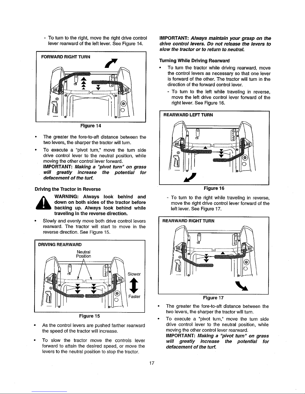
- Toturntotheright,movetherightdrivecontrol
leverrearwardoftheleftlever.SeeFigure14.
FORWARD RIGHT TURN
Figure 14
The greater the fore-to-aft distance between the
two levers, the sharper the tractor will turn.
To execute a "pivot turn," move the turn side
drive control lever to the neutral position, white
moving the other control lever forward.
IMPORTANT: Making a "pivot turn" on grass
will greatly increase the potential for
defacement of the turf.
IMPORTANT: Always maintain your grasp on the
drive control levers. Do not release the levers to
slow the tractor or to return to neutral
Turning While Driving Rearward
* To turn the tractor while driving rearward, move
the controlfevers as necessary so that one lever
is forward of the other.The tractorwillturn in the
direction of the forward controllever.
- To turn to the left while traveling in reverse,
move the leftdrive controllever forward of the
rightlever.See Figure16.
REARWARD LEFT TURN
Driving the Tractor In Reverse
WARNING: Always look behind and
down on both sides of the tractor before
backing up. Always look behind while
traveling in the reverse direction.
• Slowly and evenly move both drive control [evers
rearward. The tractor will start to move in the
reverse direction. See Figure 15.
DRIVING REARWARD
Neutral
Position
Figure 15
As the controf levers are pushed farther rearward
the speed of the tractor will increase.
To slow the tractor move the controls lever
forward to attain the desired speed, or move the
fevers to the neutral position to stop the tractor.
Figure 16
- To turn to the right while traveling in reverse,
move the right drive control lever forward of the
left lever. See Figure 17.
REARWARD RIGHT TURN
Figure 17
The greater the fore-to-aft distance between the
two levers, the sharper the tractor will turn.
To execute a "pivot turn," move the turn side
drive control lever to the neutral position, while
moving the other control lever rearward.
IMPORTANT: Making a "pivot turn" on grass
will greatly increase the potential for
defacement of the turf.
17
Page 18
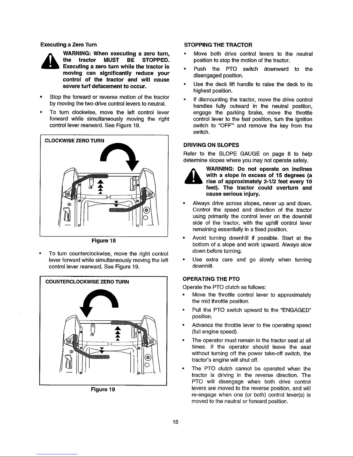
Executing a Zero Turn
_ WARNING: When executing a zero turn,
the tractor MUST BE STOPPED.
Executing a zero turn while the tractor is
moving can significantly reduce your
control of the tractor and will cause
severe turf defacement to occur.
• Stop the forward or reverse motion of the tractor
by moving the two drive control levers to neutral.
• To turn clockwise, move the left control lever
forward white simultaneously moving the right
control lever rearward. See Figure 18.
CLOCKWISE ZERO TURN
Figure 18
To turn counterclockwise, move the right control
lever forward while simultaneously moving the left
control lever rearward. See Figure 19.
COUNTERCLOCKWISE ZERO TURN
Figure 19
STOPPING THE TRACTOR
° Move both drive control levers to the neutral
position to stop the motion of thetractor.
° Push the PTO switch downward to the
disengaged position.
• Use the deck lift handle to raise the deck to its
highest position.
o If dismounting the tractor, move the drive control
handles fully outward in the neutral position,
engage the parking brake, move the throttle
control lever to the fast position, turn the ignition
switch to "OFF'" and remove the key from the
switch.
DRIVING ON SLOPES
Refer to the SLOPE GAUGE on page 8 to help
determine slopes where you may not operate safely.
_ WARNING: Do not operate on inclines
with a slope in excess of 15 degrees (a
rise of approximately 2-1/2 feet every 10
feet). The tractor could overturn and
cause serious injury.
° Always drive across slopes, never up and down.
Control the speed and direction of the tractor
using primarily the control lever on the downhill
side of the tractor, with the uphill control lever
remaining essentially in a fixed position.
• Avoid turning downhill if possible. Start at the
bottom of a slope and work upward. Always slow
down before turning.
• Use extra care and go slowly when turning
downhill.
OPERATING THE PTO
Operate the PTO clutch as follows:
• Move the throttle control lever to approximately
the mid throttle position.
• Pull the PTO switch upward to the "ENGAGED"
position.
• Advance the throttle lever to the operating speed
(full engine speed).
• The operator must remain in the tractor seat at all
times. If the operator should leave the seat
without turning off the power take-off switch, the
tractor's engine will shut off.
• The PTO clutch cannot be operated when the
tractor is driving in the reverse direction. The
PTO will disengage when both drive control
levers are moved to the reverse position, and will
re-engage when one (or both) control lever(s) is
moved to the neutral or forward position.
18
Page 19
USING THE MOWER DECK
WARNING: Make certain the area to be
mowed is free of debris, sticks, stones,
wire or other objects that can be thrown
by the rotating blades.
IMPORTANT: Do not engage the mower deck when
lowered in grass. Premature wear and possible failure
of the "V" belt and PTO clutch will result. Fully raise
the deck or move to a non grassy area before
engaging the mower deck.
• Mow across slopes, not up and down. If mowing
a slope, start at bottom and work upward to
ensure turns are made uphill.
• On the first pass pick a point on the opposite side
of the area to be mowed.
• Engage the PTO clutch using the PTO switch and
move the throttle control to the fast position.
• Lower the mower deck to the desired height
setting using the lift handle.
• Slowly and evenly push the RH and LH drive
control levers forward to move the tractor
forward, and keep the tractor headed directly
toward the alignment point.
NOTE: The speed of the tractor will affect the
quality of the mower cut. Mowing at full speed will
adversely affect the cut quality. Control the
ground speed with the control levers.
• When approaching the other end of the strip,
slow down or stop before turning. A U-turn is
recommended unless a pivot or zero turn is
required.
• Align the mower with an edge of the mowed strip
and overlap approximately 3 inches.
• Direct the tractor on each subsequent strip to
align with a previously cut strip.
• To prevent rutting or grooving of the tuff, if
possible, change the direction that the strips are
mowed by approximately 45 ° for the next and
each subsequent mowing.
_k WARNING: Be careful when crossing
gravel paths or driveways. Disengage
the PTO and raise the deck to the
highest position before crossing.
IMPORTANT: When stopping the tractor for any
reason while on a grass surface, always:
• Place the shift lever in neutral,
• Engage the parking brake,
• Shut engine off and remove the key.
Doing so will minimize the possibility of having your
lawn "browned" by hot exhaust from your tractor's
running engine.
CHECKING THE SAFETY INTERLOCK CIRCUITS
Periodically check the safety interlock circuits to
ensure they are workingproperly. If a safety circuitis
not working as designed, contact you Cub Cadet
dealer to have the tractorinspected. DO NOT operate
the tractor if any safety circuit is not functioning
properly. To check the safet_j circuits, proceed as
follows:
Sitting in the tractor seat with both drive control
levers opened fully outward, disengage the
parking brake and momentarily turn the ignition
switch to the start position. The engine should not
crank.
• Engage the parking brake and pull the PTO
switch upward to the engaged position.
Momentarily turn the ignition switch to the start
position; the engine should not crank.
• Push the PTO switch downward to the disen-
gaged position and engage the parking brake.
Start the engine and move one of the drive con-
trol levers from the fully outward neutral position.
The engine should stop running. Repeat the pro-
cedure with the opposite control lever.
• Move both control levers fully outward in the neu-
tral position and disengage the parking brake;
then lift upward from the operator's seat. The
engine should stop.
• With both control levers fully outward in the neu-
tral position and the parking brake engaged,
engage the PTO. Lift upward from the operator's
seat; the engine should stop.
• Start the tractor, disengage the parking brake,
and move the control levers inward to the neutral
operating position. Engage the PTO and move
both control lever slowly into the slow reverse
position; the PTO should disengage and the
mower deck should stop until one or both of the
control levers is moved to the neutral or forward
position.
19
Page 20
SECTION 3: ADJUSTMENTS
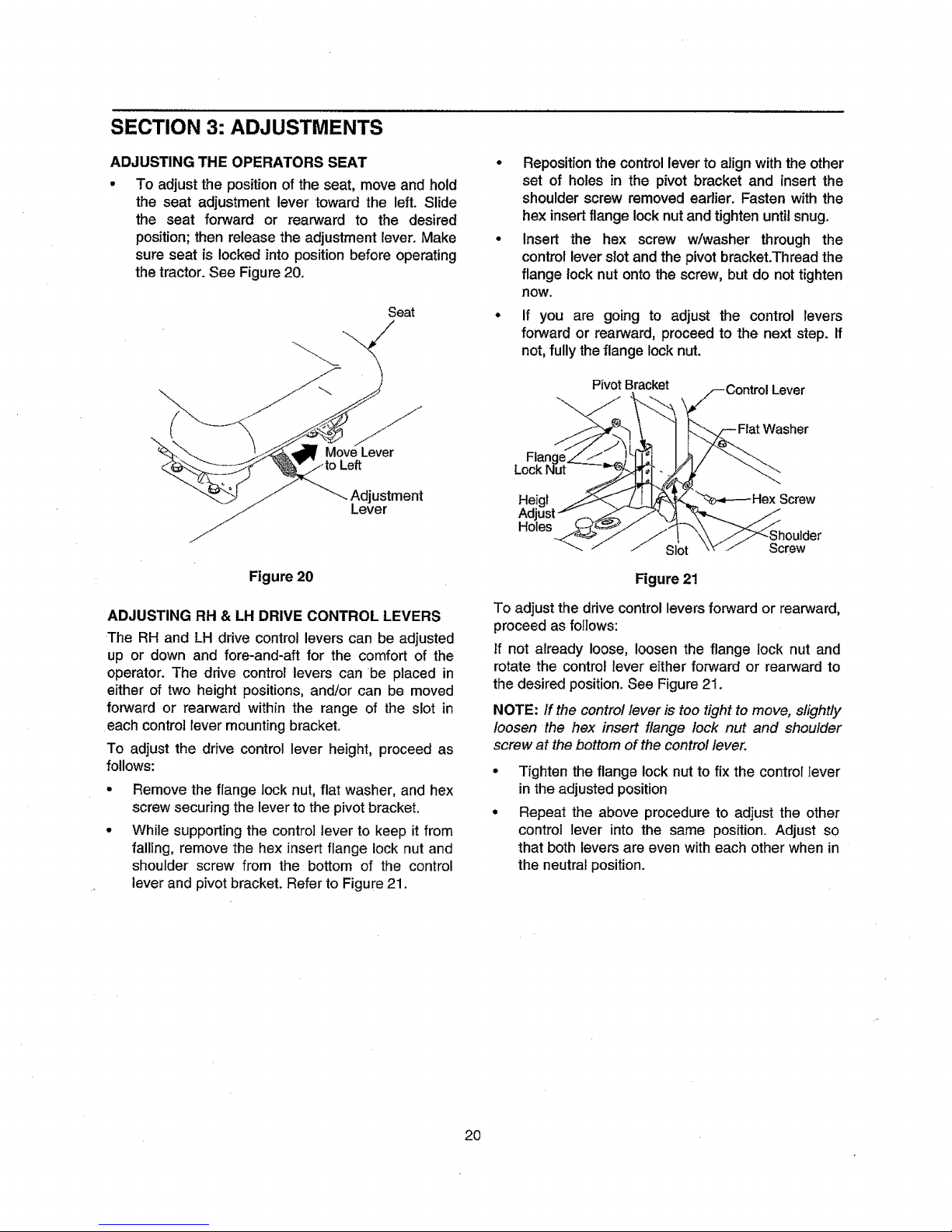
ADJUSTING THE OPERATORS SEAT
• To adjustthe positionof the seat, move and hold
the seat adjustment lever toward the left. Slide
the seat forward or rearward to the desired
position;then release the adjustmentlever. Make
sure seat is locked into positionbeforeoperating
thetractor.See Figure20,
Seat
Figure 20
ADJUSTING RH & LH DRIVE CONTROL LEVERS
The RH and LH drive control levers can be adjusted
up or down and fore-and-aft for the comfort of the
operator. The drive control levers can be placed in
either of two height positions, and/or can be moved
forward or rearward within the range of the slot in
each control lever mounting bracket.
To adjust the drive control lever height, proceed as
follows:
Remove the flange lock nut, flat washer, and hex
screw securing the lever to the pivot bracket.
While supporting the control lever to keep it from
falling, remove the hex insert flange lock nut and
shoulder screw from the bottom of the control
lever and pivot bracket. Refer to Figure 21.
° Reposition the control lever to align with the other
set of holes in the pivot bracket and insert the
shoulder screw removed earlier. Fasten with the
hex insert flange lock nut and tighten until snug.
o Insert the hex screw w/washer through the
control lever slot and the pivot bracket.Thread the
flange lock nut onto the screw, but do not tighten
now.
If you are going to adjust the control levers
forward or rearward, proceed to the next step. If
not, fully the flange lock nut.
PivotBracket
Screw
Figure 21
To adjust the drive control levers forward or rearward,
proceed as follows:
If not already loose, loosen the flange lock nut and
rotate the control lever either forward or rearward to
the desired position. See Figure 21.
NOTE: If the control lever is too tight to move, slightly
loosen the hex insert flange lock nut and shoulder
screw at the bottom of the control lever.
Tighten the flange lock nut to fix the control lever
in the adjusted position
Repeat the above procedure to adjust the other
control lever into the same position. Adjust so
that both levers are even with each other when in
the neutrat position.
20
Page 21
SECTION 4: MAINTENANCE
ENGINE MAINTENANCE
Engine maintenance procedures and schedules can
be found in the copy of the engine manual found at
the end of this manual. Follow those schedules for
performingengine maintenance.
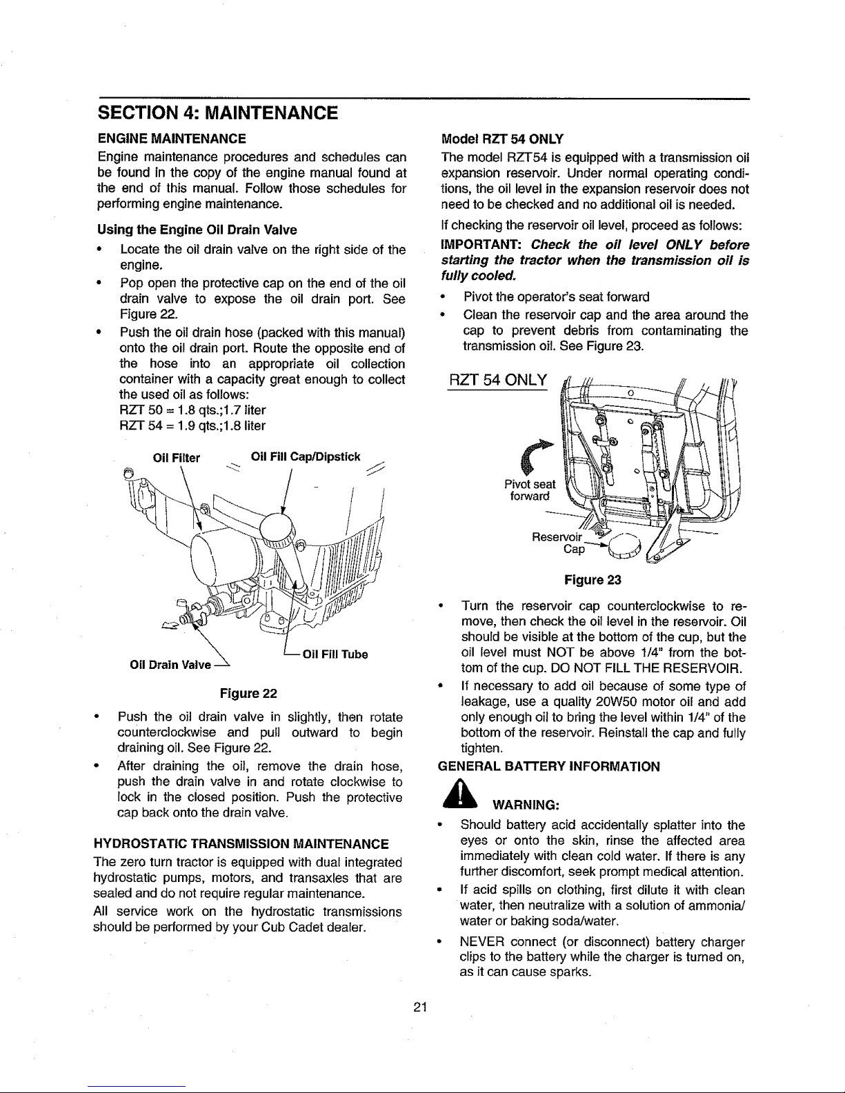
Using the Engine Oil Drain Valve
• Locate the oildrain vaXveon the rightside of the
engine.
• Pop open the protective cap on the end of the oil
drain valve to expose the oil drain port. See
Figure 22.
• Push the oil drain hose (packed with this manual)
onto the oil drain port. Route the opposite end of
the hose into an appropriate oil collection
container with a capacity great enough to collect
the used oilas follows:
RZT 50 = 1.8 qts.;1.7liter
RZT 54 = 1.9 qts.;1.8liter
Oil Filter OilFill Cap/Dipstick
Oil Drain Valve
Oil Fill Tube
Figure 22
Push the oil drain valve in slightly, then rotate
counterclockwise and pull outward to begin
draining oil. See Figure 22.
After draining the oil, remove the drain hose,
push the drain valve in and rotate clockwise to
lock in the dosed position. Push the protective
cap back onto the drain valve.
HYDROSTATIC TRANSMISSION MAINTENANCE
The zero turn tractor is equipped with dual integrated
hydrostatic pumps, motors, and transaxles that are
sealed and do not require regular maintenance.
All service work on the hydrostatic transmissions
should be performed by your Cub Cadet dealer.
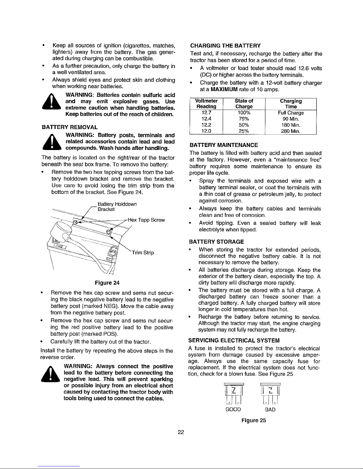
Model RZT 54 ONLY
The model RZT54 is equippedwith a transmissionoil
expansion reservoir. Under normal operating condi-
tions,the oil level in the expansion reservoir does not
need to be checked and no additional oil is needed.
if checking the reservoir oil level, proceed as follows:
IMPORTANT: Check the oil level ONLY before
starting the tractor when the transmission oil is
fully cooled,
• Pivotthe operator'sseat forward
• Clean the reservoircap and the area aroundthe
cap to prevent debris from contaminating the
transmissionoil. See Figure23.
RZT 54 ONLY
Pivotseat
forward
Figure 23
• Turn the reservoir cap counterclockwise to re-
move, then check the oil level in the reservoir. Oil
should be visible at the bottom of the cup, but the
oil level must NOT be above 1/4" from the bot-
tom of the cup. DO NOT FILL THE RESERVOIR.
= If necessary to add oil because of some type of
leakage, use a quality 20W50 motor oil and add
only enough oil to bring the level within 1/4" of the
bottom of the reservoir. Reinstall the cap and fully
tighten.
GENERAL BATFERY INFORMATION
i_ WARNING:
• Should battery acid accidentally splatter into the
eyes or onto the skin, rinse the affected area
immediately with clean cold water. If there is any
further discomfort, seek prompt medical attention.
• If acid spills on clothing, first dilute it with clean
water, then neutralize with a solution of ammonia/
water or baking soda/water.
• NEVER connect (or disconnect) battery charger
clips to the battery while the charger is turned on,
as it can cause sparks.
21
Page 22
• Keep all sources of ignition (cigarettes, matches,
lighters) away from the battery. The gas gener-
ated during charging can be combustible.
• As a further precaution, only charge the battery in
a well ventilated area.
• Always shield eyes and protect skin and clothing
when working near batteries.
WARNING: Batteries contain sulfuric acid
and may emit explosive gases. Use
extreme caution when handling batteries.
Keep batteries out of the reach of children.
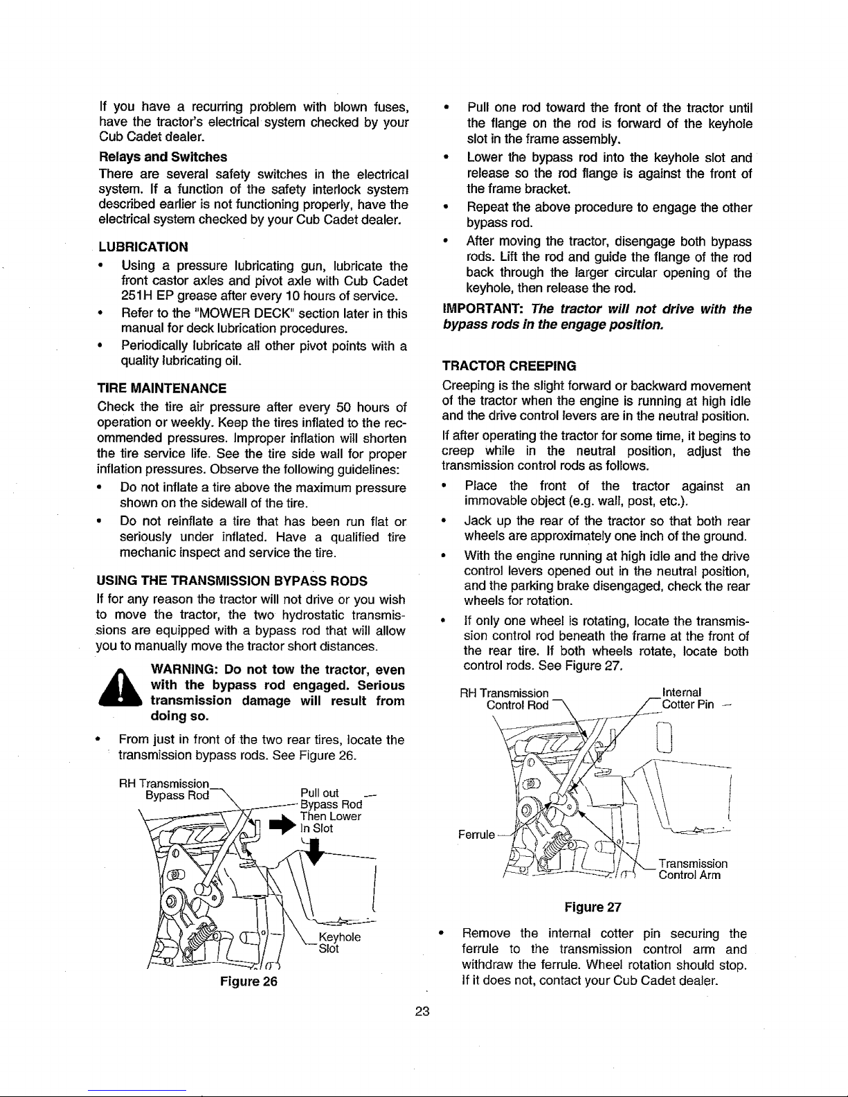
BATTERY REMOVAL
WARNING: Battery posts, terminals and
related accessories contain lead and lead
compounds. Wash hands after handling.
The battery is located on the right!rearof the tractor
beneath the seat box frame. To remove the battery:
• Remove the two hex tapping screws from the bat-
tery holddown bracket and remove the bracket.
Use care to avoid losing the trim strip from the
bottom of the bracket. See Figure 24.
Battery Holddown
___ /'_ Bracket
\ \\ ;/
",_-_
Figure 24
• Remove the hex cap screw and sems nut secur-
ing the black negative battery lead to the negative
battery post (marked NEG). Move the cable away
from the negative battery post.
• Remove the hex cap screw and sems nut secur-
ing the red positive battery lead to the positive
battery post (marked POS).
• Carefully lift the battery out of the tractor.
Install the battery by repeating the above steps in the
reverse order.
WARNING: Always connect the positive
lead to the battery before connecting the
negative lead. This will prevent sparking
or possible injury from an electrical short
caused by contacting the tractor body with
tools being used to connect the cables.
CHARGING THE BA'n'ERY
Test and, if necessary, recharge the battery after the
tractor has been stored for a period of time.
• A voltmeter or load tester should read 12.6 volts
(DC) or higher across the battery terminals.
• Charge the battery with a 12-volt battery charger
at a MAXIMUM rate of 10 amps.
Voltmeter State of Charging
Reading Charge Time
12.7 100% Full Charge
12.4 75% 90 Min.
12.2 50% 180 Min.
12.0 25% 280 Min.
BATTERY MAINTENANCE
The battery is filled with battery acid and then sealed
at the factory. However, even a "maintenance free"
battery requires some maintenance to ensure its
proper life cycle.
• Spray the terminals and exposed wire with a
battery terminal sealer, or coat the terminals with
a thin coat of grease or petroleum jelly, to protect
against corrosion.
• Always keep the battery cables and terminals
clean and free of corrosion.
• Avoid tipping. Even a sealed battery will leak
electrolyte when tipped.
BATTERY STORAGE
° When storing the tractor for extended periods,
disconnect the negative battery cable, it is not
necessary to remove the battery.
• All batteries discharge during storage. Keep the
exterior of the battery clean, especially the top. A
dirty battery wilt discharge more rapidly.
• The battery must be stored with a full charge. A
discharged battery can freeze sooner than a
charged battery. A fully charged battery will store
longer in cold temperatures than hot.
• Recharge the battery before returning to service.
Although the tractor may start, the engine charging
system may not fully recharge the battery.
SERVICING ELECTRICAL SYSTEM
A fuse is installed to protect the tractor's electrical
system from damage caused by excessive amper-
age. Always use the same capacity fuse for
replacement. If the electrical system does not func-
tion, check for a blown fuse. See Figure 25
T
GOOD BAD
Figure 25
22
Page 23
If you have a recurring problem with blown fuses,
have the tractor's electrical system checked by your
Cub Cadet dealer.
Relays and Switches
There are several safety switches in the electrical
system. If a function of the safety interlock system
described earlier is not functioning properly, have the
electrical system checked by your Cub Cadet dealer.
LUBRICATION
• Using a pressure lubricating gun, lubricate the
front castor axles and pivot axle with Cub Cadet
251H EP grease after every 10 hours of service.
• Refer to the "MOWER DECK" section later in this
manual for deck lubrication procedures.
° Periodically lubricate all other pivot points with a
quality lubricating oil.
TIRE MAINTENANCE
Check the tire air pressure after every 50 hours of
operation or weekly. Keep the tires inflated to the rec-
ommended pressures. Improper inflation witl shorten
the tire service life. See the tire side wall for proper
inflation pressures. Observe the following guidelines:
• Do not inflate a tire above the maximum pressure
shown on the sidewall of the tire.
• Do not reinflate a tire that has been run flat or
seriously under inflated. Have a qualified tire
mechanic inspect and service the tire.
USING THE TRANSMISSION BYPASS RODS
If for any reason the tractor will not drive or you wish
to move the tractor, the two hydrostatic transmis-
sions are equipped with a bypass rod that will allow
youto manually movethe tractorshort distances.
_ WARNING: Do not tow the tractor, even
with the bypass rod engaged. Serious
transmission damage will result from
doing so.
• From just in front of the two rear tires, locate the
transmission bypass rods. See Figure 26.
RH Transmission
Pullout
Bypass Rod
i_ Then Lower
In Slot
Figure 26
• Pull one rod toward the front of the tractor until
the flange on the rod is forward of the keyhole
slot in the frame assembly.
° Lower the bypass rod into the keyhole slot and
release so the rod flange is against the front of
the frame bracket.
° Repeat the above procedure to engage the other
bypass rod.
- After moving the tractor, disengage both bypass
rods. Lift the rod and guide the flange of the rod
back through the larger circular opening of the
keyhole, then release the rod.
IMPORTANT: The tractor will not drive with the
bypass rods in the engage position.
TRACTOR CREEPING
Creeping is the slight forward or backward movement
of the tractorwhen the engine is running at high idle
and the drive control levers are in the neutral position.
If after operating the tractor for some time, it begins to
creep while in the neutral position, adjust the
transmission control rods as follows.
• Place the front of the tractor against an
immovable object (e.g. wall, post, etc.).
• Jack up the rear of the tractor so that both rear
wheels are approximately one inch of the ground.
• With the engine running at high idle and the drive
control levers opened out in the neutral position,
and the parking brake disengaged, check the rear
wheels for rotation.
If only one wheel is rotating, locate the transmis-
sion controlrod beneath the frame at the front of
the rear tire. If both wheels rotate, locate both
control rods. See Figure27.
RH Transmission Internal
Control
Ferrule
Transmission
Control Arm
Figure 27
Remove the internal cotter pin securing the
ferrule to the transmission control arm and
withdraw the ferrule. Wheel rotation should stop.
If it does not, contact your Cub Cadet dealer.
23
Page 24
• Ifthe rotation stops, adjust the ferrule up or down
the control rod as necessary to align with the hole
in the transmission control arm, Re-insert the
ferrule into the hole in the control arm and secure
with the internal cotter pin.
• If necessary, repeat the previous two steps to
adjust the other transmission control rod.
• Lower the tractor and remove the jack.
TRACTOR HIGH SPEED TRACKING
If the tractor tracks to one side withboth drive control
levers fully forward, adjust the control levers as
follows:
• Check for proper and balanced air pressure in
both front and rear tires.Refilltiresif necessary.
• Perform the first three steps in the previous sub-
section,Tractor Creeping, to verifythat the tractor
is not creeping. If creeping, adjust following the
instructionsinthat sub-section.
• Recheck the tracking after making any adjust-
ments tothetransmissioncontrolrods.
• If uneven tracking persists,note which direction
the tractoris tracking.
- If the tractor tracks to the right, adjust the
controllever stop bolt onthe leftside.
- If thetractortracksto the left, adjust the control
leverstop bolton the right side.
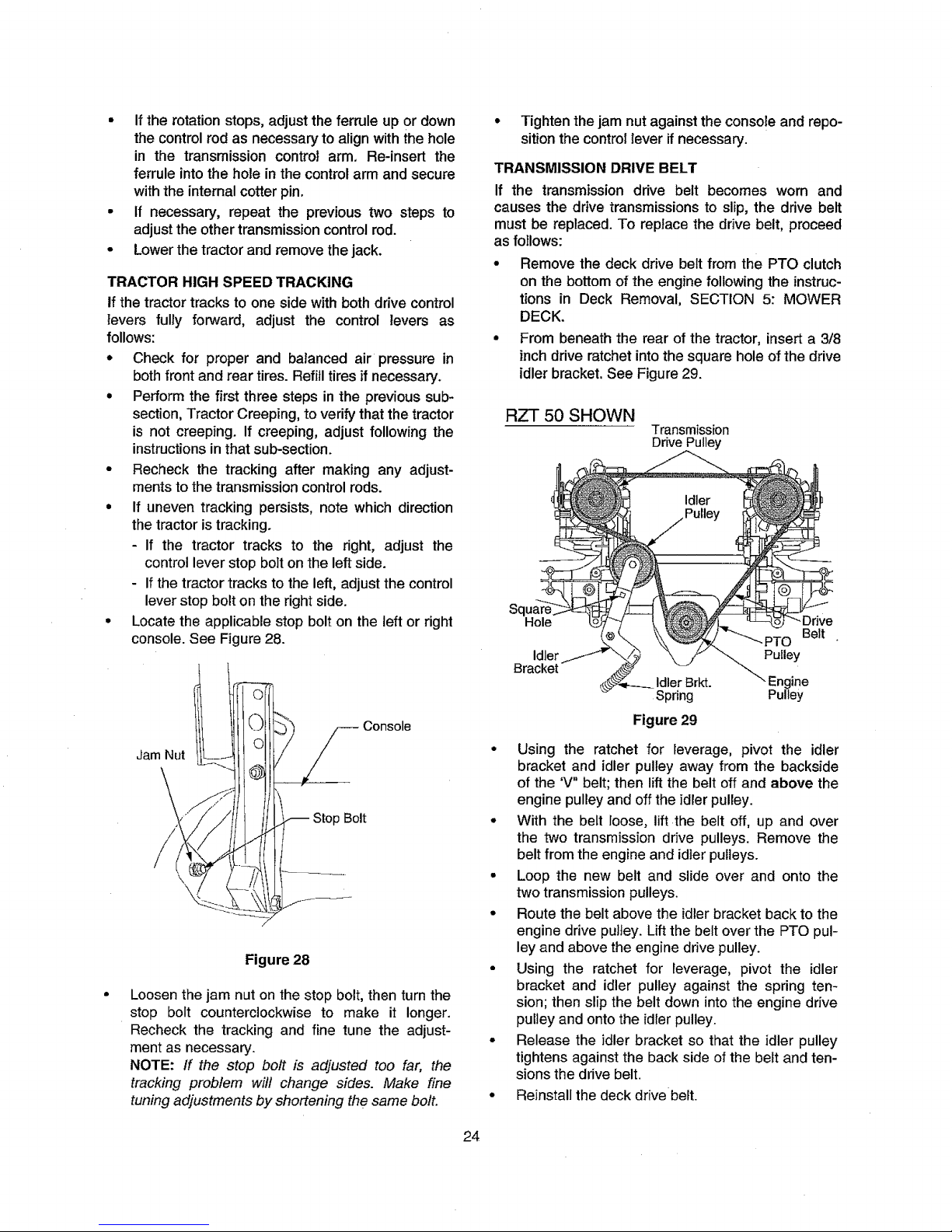
• Locatethe applicable stop bolt on the leftor right
console.See Figure 28.
Jam Nut
Stop Bolt
Figure 28
Loosen the jam nut on the stop bolt, then turn the
stop bolt counterclockwise to make it longer.
Recheck the tracking and fine tune the adjust-
ment as necessary.
NOTE: ff the stop bolt is adjusted too far, the
tracking problem will change sides. Make fine
tuning adjustments by shortening the same bolt.
• Tighten the jam nut against the console and repo-
sition the control lever if necessary.
TRANSMISSION DRIVE BELT
If the transmission drive belt becomes worn and
causes the drivetransmissionsto slip,the drive belt
must be replaced. To replace the drive belt, proceed
as follows:
• Removethe deck drive belt from the PTO clutch
on the bottom of the engine following the instruc-
tions in Deck Removal, SECTION 5: MOWER
DECK.
• From beneath the rear of the tractor, insert a 3/8
inch drive ratchet into the square hole of the drive
idler bracket, See Figure 29.
RZT 50 SHOWN
Transmission
DrivePulley
Sq
Hole
Belt
Idler Pulley
Bracket
Idler Brkt. ine
Spring Pulley
Figure 29
• Using the ratchet for leverage, pivot the idler
bracket and idler pulley away from the backside
of the 'V" belt; then lift the belt off and above the
engine pulley and off the idler pulley.
• With the belt loose, lift the belt off, up and over
the two transmission drive pulleys. Remove the
belt from the engine and idier pulleys.
• Loop the new belt and slide over and onto the
two transmission pulleys.
• Route the belt above the idlerbracket back to the
engine drive pulley. Lift the belt over the PTO pul-
ley and above theengine drive pulley.
• Using the ratchet for leverage, pivot the idler
bracket and idler pulley against the spring ten-
sion; then slip the belt down intothe engine drive
pulley and onto the idler pulley.
• Release the idler bracket so that the idler pulley
tightens against the back side ofthe beltand ten-
sions the drive belt.
• Reinstallthe deck drive belt.
24
Page 25
TRACTOR STORAGE
If your tractor is not going to be operated for an
extended period of time (thirty days to approximately
six months), the tractor should be prepared for stor-
age. Store the tractor in a dry and protected location.
If stored outside, cover the tractor (including the tires)
to protect it from the elements. The procedures out-
lined below should be performed whenever the tractor
is placed in storage.
1. Change the engine oil and filter following the
instructions provided in the engine manual
packed with this manual.
_ WARNING: Never store the tractor with
fuel in the tank indoors or in poorly ven-
tilated enclosures, where fuel fumes may
reach an open flame, spark or pilot light
as on a furnace, water heater, clothes
dryer, etc.
_ ARNING: Fuel left in the fuel tank dete-
riorates and will cause serious starting
problems.
2.
If storing the tractor for 30 days or more:
To prevent gum deposits from forming inside the
engine's carburetor and causing possible malfunc-
tion of the engine, the fuel system must be either
completely emptied, or the gasoline must be
treated with a stabilizer to prevent deterioration.
Using a fuel stabilizer:
* Read the product manufacturer's instructions
and recommendations.
- Add to clean, fresh gasoline the correct amount
of stabilizer for the capacity (approximately 3
gallons) of the fuel system.
• Fill the fuel tank with treated fuel and run the
engine for 2-3 minutes to get stabilized fuel into
the carburetor.
Emptying the fuel system:
• Prior to putting the tractor in storage, monitor
fuel consumption with the goal of running the
fuel tank empty.
• Run the engine until it begins to stall. Use the
choke to keep the engine running until all fuel in
the carburetor has been exhausted.
• Referring to the engine manual, drain the fue!
from the carburetor bowl.
3. Clean the engine and the entire tractor
thoroughly.
4. Fully charge the battery, then disconnect the neg-
ative cable at the battery to prevent possible
discharge. Recharge the battery periodically
when in storage. NOTE: Remove the battery if
exposed to prolonged periods of sub-freezing
temperatures. Store in a cool dry/ocation where
temperatures are above freezing.
5. Lubricate a_Jlubrication points.
NOTE: We do not recommend the use of a pressure
washer or garden hose to clean your tractor. They may
cause damage to electrical components; spindles;
pulleys; bearings; or the engine. The use of water will
result in shortened life and reduce serviceability.
REMOVING THE TRACTOR FROM STORAGE
• Check the engine oil.
• Fully charge the battery and inflate the tires to the
recommended pressure.
• If drained before storing, fill the fuel tank with
clean, fresh gasol}ne.
• Add clean, fresh fuel.
• Start the engine and allow to idle for a few
minutes to ensure engine is operating properly.
• Drive the tractor without a lead to make certain all
the tractor systems are functioning properly.
25
Page 26
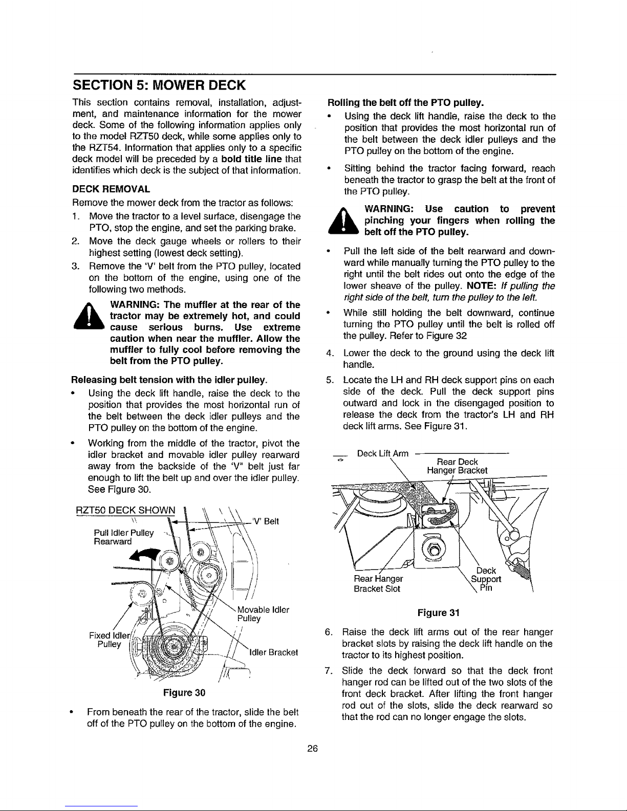
SECTION 5: MOWER DECK
This section contains removal, installation, adjust-
ment, and maintenance information for the mower
deck. Some of the following information applies only
to the model RZT50 deck, while some applies only to
the RZT54. information that applies only to a specific
deck model will be preceded by a bold title line that
identifies which deck is the subject of that information.
DECK REMOVAL
Remove the mower deck from the tractor as follows:
1. Move the tractor to a level surface, disengage the
PTO, stop the engine, and set the parking brake.
2. Move the deck gauge wheels or rollers to their
highest setting (lowest deck setting).
3. Remove the 'V' belt from the PTO pulley, located
on the bottom of the engine, using one of the
following two methods.
d_lb WARNING: The muffler at the rear of the
tractor may be extremely hot, and could
cause serious burns. Use extreme
caution when near the muffler. Allow the
muffler to fully cool before removing the
belt from the PTO pulley.
Releasing belt tension with the idler pulley.
• Using the deck lift handle, raise the deck to the
position that provides the most horizontal run of
the belt between the deck idler pulleys and the
PTO pulley on the bottom of the engine.
• Working from the middle of the tractor, pivot the
idler bracket and movable idler pulley rearward
away from the backside of the 'V" belt just far
enough to lift the belt up and over the idler pulley.
See Figure 30.
RZTb0 DECK SHOWN
\\,
Pull Idler Pulley
Rearward
Belt
Fixed Idler
Pulley
Movable Idler
Pulley
s'/
/
Figure 30
From beneath the rear of the tractor, slide the belt
off of the PTO pulley on the bottom of the engine.
Rolling the belt off the PTO pulley.
• Using the deck lift handle, raise the deck to the
position that provides the most horizontal run of
the belt between the deck idler pulleys and the
PTO pulley on the bottom of the engine.
• Sitting behind the tractor facing forward, reach
beneath the tractor to grasp the belt at the front of
the PTO pulley.
_iL ARNING: Use caution to prevent
pinching your fingers when rolling the
belt off the PTO pulley.
• Pull the left side of the belt rearward and down-
ward while manually turning the PTO pulley to the
right until the belt rides out onto the edge of the
lower sheave of the pulley. NOTE: If pulling the
right side of the belt, turn the pulley to the left.
• While still holding the belt downward, continue
turning the PTO pulley until the belt is rolled off
the pulley. Refer to Figure 32
4.
5.
6.
7.
Lower the deck to the ground using the deck lift
handle.
Locate the LH and RH deck support pins on each
side of the deck. Pull the deck support pins
outward and lock in the disengaged position to
release the deck from the tractor's LH and RH
deck lift arms. See Figure 31.
Deck Lift Arm
Rear Deck
Hanger Bracket
Rear Hanger
Bracket Slot
Figure 31
Raise the deck lift arms out of the rear hanger
bracket slots by raising the deck lift handle on the
tractor to its highest position.
Slide the deck forward so that the deck front
hanger rod can be lifted out of the two slots of the
front deck bracket. After lifting the front hanger
rod out of the slots, slide the deck rearward so
that the rod can no longer engage the slots.
26
Page 27
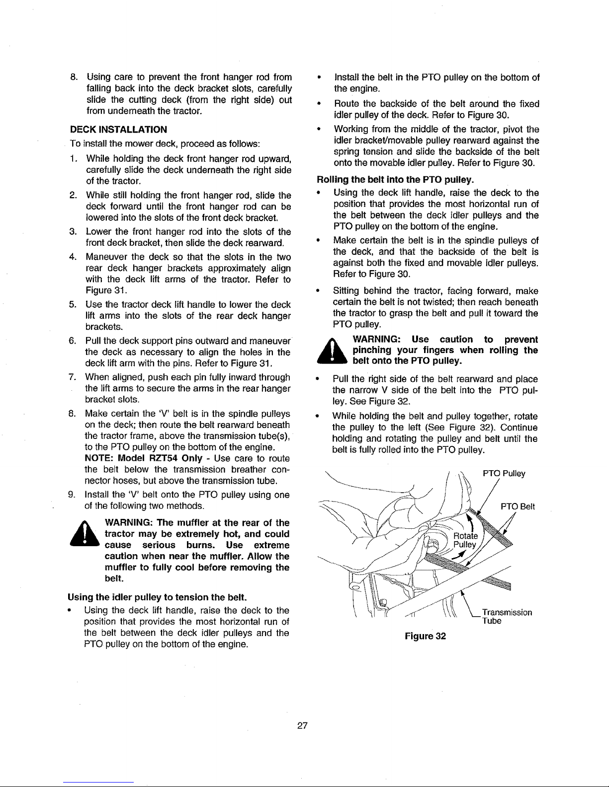
=
Using care to prevent the front hanger rod from
falling back into the deck bracket slots, carefully
slide the cutting deck (from the right side) out
from underneath the tractor.
DECK INSTALLATION
To install the mower deck, proceed as follows:
1. While holdingthe deck front hanger rod upward,
carefully slide the deck underneaththe right side
ofthe tractor.
2. While still holding the front hanger rod, slide the
deck forward until the front hanger rod can be
loweredinto the slots of the front deck bracket.
3. Lower the front hanger rod intothe slots of the
front deck bracket,then slide the deckrearward.
4. Maneuver the deck so that the slots in the two
rear deck hanger brackets approximately align
with the deck lift arms of the tractor. Refer to
Figure31.
5. Use the tractordeck lift handle to lower the deck
lift arms into the slots of the rear deck hanger
brackets.
6. Pullthe deck support pins outwardand maneuver
the deck as necessary to align the holes in the
deck liftarmwiththe pins. Refer to Figure31.
7. When aligned, push each pinfullyinwardthrough
the lift arms to secure the arms inthe rear hanger
bracket slots.
8. Make certain the 'V' belt is in the spindle pulleys
on the deck; then route the belt rearward beneath
the tractorframe, above the transmissiontube(s),
tothe PTO pulley on the bottom ofthe engine.
NOTE: Model RZT54 Only - Use care to route
the belt below the transmission breather con-
nector hoses, but above the transmission tube.
9. Install the 'V' belt onto the PTO pulley using one
of the following two methods.
,_ WARNING: The muffler at the rear of the
tractor may be extremely hot, and could
cause serious burns. Use extreme
caution when near the muffler. Allow the
muffler to fully cool before removing the
belt.
Using the idler pulley to tension the belt.
• Using the deck lift handle, raise the deck to the
position that provides the most horizontal run of
the belt between the deck idler pulleys and the
PTO pulley on the bottom of the engine.
• Install the belt in the PTO pulley on the bottom of
the engine.
• Route the backside of the belt around the fixed
idler pulley of the deck. Refer to Figure 30.
• Working from the middle of the tractor, pivot the
idler bracket/movable pulley rearward against the
spring tension and slide the backside of the belt
onto the movable idler pulley. Refer to Figure 30.
Rolling the belt into the PTO pulley.
° Using the deck lift handle, raise the deck to the
position that provides the most horizontal run of
the belt between the deck idler pulleys and the
PTO pulleyonthe bottomof the engine.
• Make certain the belt is in the spindle pulleysof
the deck, and that the backside of the belt is
againstboth the fixed and movable idler pulleys.
Refer to Figure30.
• Sitting behind the tractor, facing forward, make
certain the belt is not twisted; then reach beneath
the tractor to grasp the belt and pull it toward the
PTO pulley.
WARNING: Use caution to prevent
pinching your fingers when rolling the
belt onto the PTO pulley.
• Pull the right side of the belt rearward and place
the narrow V side of the belt into the PTO pul-
ley. See Figure 32.
• While holding the belt and pulley together, rotate
the pulley to the left (See Figure 32). Continue
holding and rotating the pulley and belt until the
belt is fully roiled into the PTO pulley.
PTO Pulley
PTO Belt
Figure 32
Transmission
Tube
27
Page 28
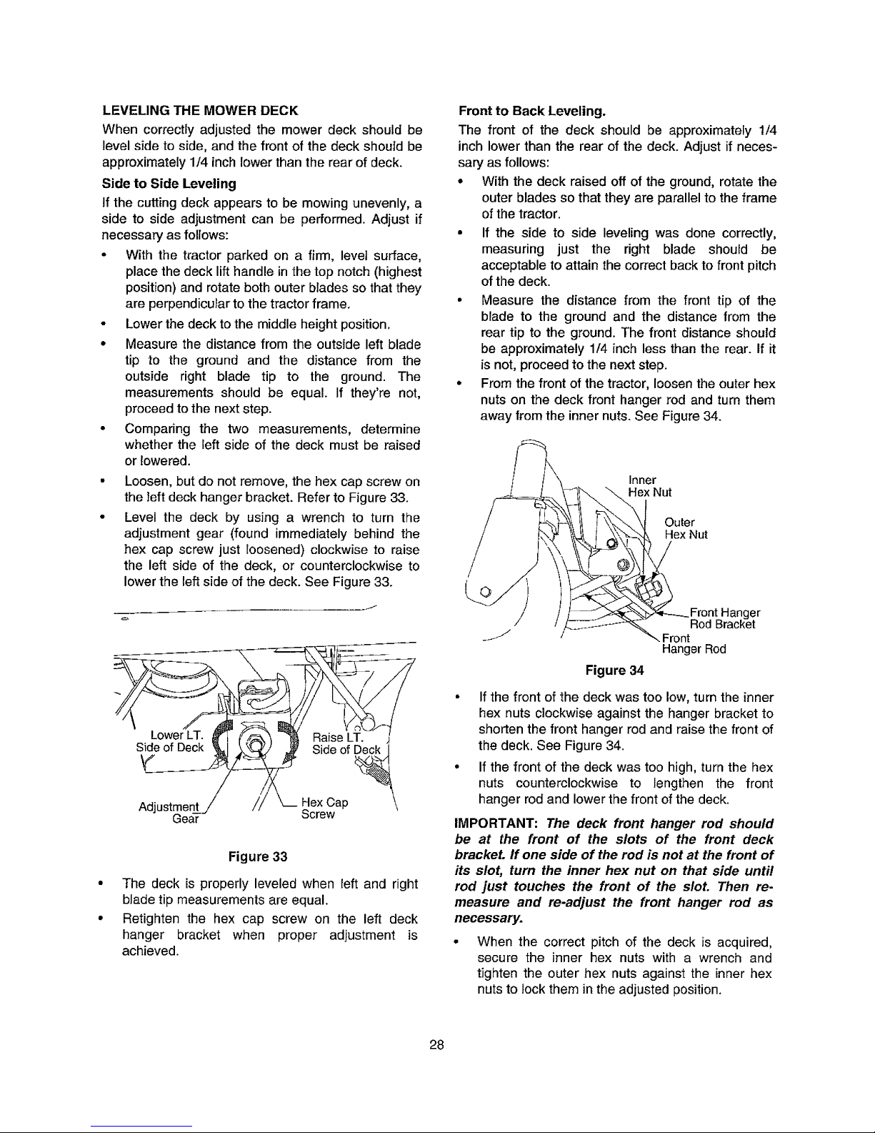
LEVELING THE MOWER DECK
When correctly adjusted the mower deck should be
level side to side, and the front of the deck should be
approximately 1/4 inch lower than the rear of deck.
Side to Side Leveling
If the cutting deck appears to be mowing unevenly, a
side to side adjustment can be performed. Adjust if
necessary as follows:
• With the tractor parked on a firm, level surface,
place the deck lift handle in the top notch (highest
posiUon) and rotate both outer blades so that they
are perpendicutar to the tractor frame.
• Lower the deck to the middle height position.
• Measure the distance from the outside left blade
tip to the ground and the distance from the
outside right blade tip to the ground. The
measurements should be equal. If they're not,
proceed to the next step.
• Comparing the two measurements, determine
whether the left side of the deck must be raised
or lowered.
• Loosen, but do not remove, the hex cap screw on
the left deck hanger bracket. Refer to Figure 33.
• Level the deck by using a wrench to turn the
adjustment gear (found immediately behind the
hex cap screw just loosened) clockwise to raise
the left side of the deck, or counterclockwise to
lower the left side of the deck. See Figure 33.
yJ
Side of Deck _1 _.%_J J_ Side of Deck 1
Adjustmer // _ Hex Cap
Gear Screw
Figure 33
• The deck is properly leveled when reft and right
blade tip measurements are equal.
• Retighten the hex cap screw on the left deck
hanger bracket when proper adjustment is
achieved.
Front to Back Leveling.
The front of the deck should be approximately 1/4
inch lower than the rear of the deck. Adjust if neces-
sary as follows:
• With the deck raised off of the ground, rotate the
outer blades so that they are parallel to the frame
of the tractor.
• If the side to side leveling was done correctly,
measuring just the right blade should be
acceptable to attain the correct back to front pitch
of the deck.
• Measure the distance from the front tip of the
blade to the ground and the distance from the
rear tip to the ground. The front distance should
be approximately 1/4 inch less than the rear. If it
is not, proceed to the next step.
• From the front of the tractor, loosen the outer hex
nuts on the deck front hanger rod and turn them
away from the inner nuts. See Figure 34.
/
/
/
/
J
Inner
H__ex Nut
+ OeUtxeNut
_._ ;:;_--_._Front Hanger
Rod Bracket
Front
Hanger Rod
Figure 34
• If the front of the deck was too low, turn the inner
hex nuts clockwise against the hanger bracket to
shorten the front hanger rod and raise the front of
the deck. See Figure 34.
• If the front of the deck was too high, turn the hex
nuts counterclockwise to lengthen the front
hanger rod and lower the front of the deck.
IMPORTANT: The deck front hanger rod should
be at the front of the slots of the front deck
bracket, if one side of the rod is not at the front of
its slot, turn the inner hex nut on that side until
rod just touches the front of the slot. Then re-
measure and re-adjust the front hanger rod as
necessary.
When the correct pitch of the deck is acquired,
secure the inner hex nuts with a wrench and
tJghten the outer hex nuts against the inner hex
nuts to lock them in the adjusted position.
28
Page 29

ADJUSTING THE GAUGE WHEELS AND ROLLERS
WARNING: Keep hands and feet away
from the discharge opening of the
cutting deck.
Model RZT50 Gauge Wheels
NOTE: The deck gauge wheels are an anti-scalp fea-
ture of the deck and are not designed to support the
weight of the cutting deck.
The mower deck cutting height can be set in any of
six height settings using the tractor's deck lift handle.
The deck heights range from 1-1/2" to 4". For the
model RZT50, the deck gauge wheel position should
be approximately 1/4 to 1/2 inch above the ground
when the deck is set in the desired height setting.
Using the lift handle, set the deck in the desired
height setting, then check the gauge wheel distance
from the ground below, if necessary adjust as follows:
• Visually check the distance between the front
gauge wheels and the ground. If the gauge
wheels are near or touching the ground, they
should be raised. If more than 1/2" above the
ground, they should be lowered.
° Remove the lock nut securing one of the front
gauge wheel shoulder screws to the deck.
Remove the gauge wheel and shoulder screw.
See Figure 35.
• Insert the shoulder screw into the one of four
index holes in the front gauge wheel bracket that
will give the gauge wheel a 1/4 to 1/2 inch
clearance with the ground.
• Note the index hole of the just adjusted wheel,
and adjust the other gauge wheels into the
respective index holes of the other gauge wheel
brackets on the deck.
RZT 50 Shoulder
Screw
^ "-_...iF "_. Front Gauge
_ t=auge ! FF_ t_-- Wh_,_l
Hear uauge Wheel \ i_ .....
Wheel Bracket _<_
_ /./_° Adjustment i_-¢.
}"_--b/ _._ _ _ Index _-"//"
/ /,_1__--_ . . Holes / t
t _ ,'_-_7/H2____ \ Lock P__,,_, Lock
-=cr'e_w_" -_ Bracket
Figure 35
Model RZT54 Gauge Wheels and Rollers
The front gauge wheels on the RZT54 mower deck
are an antkscalp feature, and should not ride on the
ground. The front gauge wheels should be approxi-
mately 1/4 to 1/2 inch above the ground when the
deck is set inthe desired height setting.
The rear deck rollers can be set in either the tow or
high position.
Using the lift handle, set the deck in the desired
height setting, then check the gauge wheel distance
from the ground below. If necessary adjust the front
gauge wheels as follows:
° Visually check the distance between the front
gauge wheels and the ground. If the gauge
wheels are near or touching the ground, they
should be raised. If more than 1/2" above the
ground, they should be lowered,
° Remove the lock nut securing one of the front
gauge wheel shoulder screws to the deck.
Remove the gauge wheel and shoulder screw.
Refer to Figure 35.
° Insert the shoulder screw into the one of four
index holes in the front gauge wheel bracket that
will give the gauge wheel a 1/4 to 1/2 inch
clearance with the ground.
• Note the index hole of the just adjusted wheel,
and adjust the other front gauge wheel into the
respective index hole of the other front gauge
wheel bracket.
The position on the rear deck rollers is generally not
changed. In the low position the rollers will roll the
grass. In the high position, the rollers are in a storage
position and do little or no rolling of the grass.
Change the roller position as follows:
• Remove the cotter pin from the left end of the
roller shaft. See Figure 36.
• Slide the roller shaft to the right and remove the
rollers as the shaft is fully withdrawn from the
right rear roller bracket. See Figure 36.
RZT 54 High
Position Low Position
C_itter _ / _, Right Rear
_,' / _ _ tl _ Roller Brkt.
Figure 36
Insert the roller shaft through the other roller
bracket hole. Slide the rollers onto the shaft as
you slide the shaft to the left.
If necessary, rotate the roller shaft to align the flat
area on the left end of the shaft with the flat of the
hole in the left roller bracket. Slide the shaft
throught the left roller bracker and secure with the
cotter pin.
29
Page 30

DECK MAINTENANCE
Using the Deck Wash System
,_ WARNING: When using the deck wash
system, never engage the deck from any
position other than the operator's seat of
the tractor. Do not use an assistant or
engage deck in the presence of any
bystanders.
• Attach the nozzle adapter to a standard garden
hose connected to a water supply.
• Move the tractor to an area within reach of the
hose where the dispersal of wet grass clippings is
not objectionable to you. Disengage the PTO,
engage the parking brake, and stop the engine.
• Pull back the lock collar of the nozzle adapter and
push the adapter onto one of the deck wash
nozzles at either end of the mower deck. Release
the lock collar to lock the adapter on the nozzle.
See Figure 37.
RZT50 Shown
\\
^_ ,^ \ _ Pull Lock
NULLI_ L ' ^
Adapter _ [ _L,oilar Back
Adapter ...__ _-__
Lock Collar I .-/_ .._}
___'_---_ Deck Wash
/ j _,_,_, Nozzle
Figure 37
• Turn on thewater supply.
• From the tractor operator's seat, start the engine
and engage the PTO. Allow to run as needed.
Disengage the PTO and stop the engine.
• Turn off the water supply.
• Pull back the lock collar of the nozzle adapter to
disconnect the adapter from the nozzle.
• Repeat the previous steps to clean the deck
using the nozzle at the other end of the deck.
Cleaning the Spindle Pulleys
Once a month remove the belt covers to remove any
accumulation of grass clippings from around the
spindle pulleys and V-belt. Clean more often when
mowing tall, dry grass.
Mower Blade Care
_ ARNING: Before performing any main-
tenance, place the PTO switch in the
"OFF" position, engage the parking
brake lever, turn the ignition key to the
"OFF" position and remove the key from
the switch.
,_WARNING: When servicing the mower
deck, be careful not to cut yourself on the
sharpened blades.
The cutting blades must be kept sharp at all times.
Sharpen the cutting edges of the blades evenly so
that the blades remain balanced and the same angle
of sharpness is maintained.
If the cutting edge of a blade has already been sharp-
ened many times, or if any metal separation is present,
it is recommended that new blades be installed. New
blades are available at your authorized dealer.
The blades may be removed as follows.
• Remove the deck from beneath the tractor, (refer
to Deck Removal on page 26) then gently flip the
deck over to expose its underside.
• Use a 15/16 inch wrench to hold the hex nut on
top of the spindle assembly when loosening the
hex nut securing the blade. A block of wood may
be placed between the deck housing and the
cutting edge of the blade to help in breaking loose
the hex nut securing the blade. Refer to Figure 38.
• When reinstalling the blades, be sure they are
installed so that the wind wings are pointing
upward toward the top of the deck.
• Tighten the blade nuts to 70-90 ft. ]bs.
• Reinstall the deck (refer to Deck Installation on
page 27).
RZT50 Shown
Hex Nut
/
Wood Block
In Position
Use 15/16"
Wrench to
Remove Nut
Figure 38
DECK LUBRICATION
After every 10 hours of operation and before
putting the deck into winter storage, lubricate
the spindle assemblies with 251H EP grease or
an equivalent No. 2 multipurpose lithium
grease. The lube fittings are located in the
spindle housing and can be accessed from
underneath the deck.
3O
Page 31

REPLACING THE DECK DRIVE BELT
• Remove the deck from beneath the tractor, (refer
to Deck Removal on page 26).
° Remove the hex tapping screws securing the belt
covers to the deck and remove the belt from the
spindle pulleys. Refer to Figure 39.
Install the new belt around the spindle pulleys as
shown in Figure 39 and reinstall the belt covers.
Route the belt rearward between the two idler
pulleys and reinstall the deck following the
instructions in Deck Installation on page 27.
RZT50 MOWER DECK
'V' Belt
Cover
IdlerPulley IdlerPulley
Figure 39
RZT54 MOWER DECK
Figure 40
31
Page 32

ENGINE MANUAL
A Kawasaki engine is used on this RZT tractor model. The following section is a reproduction of the Kawasaki
engine manual that applies to the RZT50 and RZT54 engines. The RZT50 use the model FH661, and the RZT54
uses the model FH721V engine. Read this manual in its entirety. Observe all warnings and follow all applicable
operation and maintenance instructions provided in the manual.
NOTE: Although the engine manual provides Kawasaki service contact information, always first contact your
Cub Cadet dealer ff you experience engine problems or have questions regarding the engine.
SAFETY AWARENESS
Whenever you see the symbols shown below,
heed their instructions! Always follow safe operat-
ing and maintenance practices.
This warning symbol identifies special in-
structions or procedures which, if not cor-
rectly followed, could result in personal
injury, or loss of life.
CAUTION
This caution symbol identifies special in-
structions or procedures which, if not strictly
observed, could result in damage to, or de-
struction of equipment.
NOTE
o This note symbol indicates points of particular in-
terest for more efficient and convenient operation.
32
Page 33

READ THIS FIRST
For your safety,read this Owner's Manual and understanditthoroughlybefore operatingthis ENGINE.
DO NOT run the engine in a closed area. Exhaust gas contains carbon monoxide, an odorless and
deadly poison.
Gasoline Is extremely flammable and can be explosive under certain condition.
Stop engine and allowthe engine to cool before refu_[ng.
DO NOT smoke. Make st_e area is well ventilatedand free from any sourceofflame or sparksincluding
the pilot light ofany appliance while refueling, servicing fuel system, draining gasoline and/or adjusting
carburetor.
DO NOT fil!the tank so the fuel level rises intothe filler neck or level surfaceof revel gauge, If the tank is
overfilled, heat may causethe fuel to expand and overflowthroughthe vents in the tank cap.
Wipe off any spilledgasoline immediately.
To prevent fire hazard;
Keep tt_eengine at least I m {3.3 ft) away from buildings,obstructionsand other burnableobjects.
DO NOT place flammable objectsclose to the engine.
DO NOT expose combustible materials to the engine exhaust.
DO NOT use the engine on any forest covered, brush covered orgrass covered unimprovedland unless
spark ancestoris installedon 1hemuffler.
To avoid getting an electric shock, DO NOT touch spark plugs, plug caps or spark plug leads during
engine running.
TOavoid a serious burn, DO NOT touch a hot engine or muffler, The engine becomes hot during
operatio,. Before you service or remove parts, stop engine and allow the engine to cooL
DO NOT place hands or feet near movb_g or rotating parts. Place a protective cover over pulley, V
belt or coupling.
DO NOT run engine at excessive speeds. This may result in injury.
Always remove the spark plug caps from spark plugs when servicing the engine to prevent acci-
dental starting.
Read warning labelswhich are on the engine and understand them. tf any label is missing,damaged, or
worn get a replacementfromyour Kawesaki dealer and installit inthe correct position.
i
EMISSION CONTROL INFORMATION
Fuel Irlforrnation
THIS ENGINE tS CERTIFIED TO OPERATE ON UNLEADED REGULAR GRADE GASOLINE ONLY A min-
imum of 87 octane of the antiknock index isrecommended. The antknoCk index is posted on service station
pumps in the U.S.A.
EralsslonConbol Infonmatlon
Toprotecttheenvironmentinwhichweall live,Kaweealdhasincorporatedanexhaustemissioncontrolsya-
ternincemplian_ withapplicableregulationsof the UnitedStatesEnvironmentalProte_on Agenw andthe
CaliforniaAirResourcesBoard.Also,dependingonwhenyourenginewa_sproduced°itmayhaveanassigned
emissions durabilityperiod.* See belowfortheengineemissionsdurabilityportedthetmay,applytoyouren-
gine.
ExhaustEmissionConl='olSystem
The exhaustemissioncontrotsystemappliedto thisengineconsistsof a carburetorand anignitionsystem
havingoptimumignitiontimingcharac_dstics.The carburetorhasbeencalibratedto provideleanair/fuelmix-
turect_aracIeristlcsandoptimumfueleconomywitha suitablealr cleanerandexhaustsys_.
A sealed-typecrankcase stats=ioncordml=y_temisalso usedtoeliminal_blow-bygasses. The blow-by
gassesareledtoa breatherchamberthroughthecrankcaseandFromtheretothe aircleaner.
33
Page 34

Engine Emission Compliance Period
Califomia
Engines Greater Than 225 c¢
Model Year - 2006 and later
Durabilityperiod - 500 hours
All Other States
Engines Greater Than 225 c¢
Model Year - 200t and later
DurabilityPeriod - 1 000 hours (Category A)
* tf your engi.e has an assigned emissio.s durability period it will be located on the certification label
attached to the engine (IMPORTANT ENGINE INFORMATION).
High Altitude Performance Adjustment Information
Toimprove the EMISSIONS CONTROL PERFORMANCE of engines operated above 1,000 meters (3 300
feet), Kawasaki recommends the following EnvironmentalProtectionAgency (EPA) and the Cafifomia Air Re*
sources Board (CARB) approved modifications.
NOTE
0 When propedy performed, these specified modifications only are not consideredto be emissions system
"tampering_and engine performance is generally unchanged as a result.
Ins_lation Instructions:
High altitudeadjustment requires replacement of carburetor mainjets. Installation of these optional parts may
be performed by an authorized Kawasaki dealer, or the consumer,following repair recommendationsspecified
in the appropriate f(awasaki Service Bulletin.
Maintenance and Warranty
Propermaintenance isnecessary to ensurethatyour eng ne will continue to have low emissionlevels. This
Owner's Manualcontains those maintenance recommendations for your engine. Those itemsidentifiedby the
PeriodicMaintenance Chart are neoessary to ensure compliancewith the applicable standards,
As the ownerof the engine, you havethe responsibilityto make surethat the recommended maintenance is
carriedout according tothe instructionsinthis Owner's Manual at yourown expense.
The Kawasaki Limited Emission Control System Warranty requires that you return your engine to an autho-
rized Kawasaki dealer for remedy under warranty. Rease read the warranty carefully,and keep it valid by
complyingwith the owner's obligationsit contains.
Tampering with Emission Control System Prohibited
Federal law and California State law prohibitthe followingacts or the causing thereof: (1) the removal or
renderinginoperative by any person other than for purposesof maintenance, repair, or replacement, of any
device or element of design incorporatedintoany new engine for the purposes of emission contro!prior to its
sale or delivery to the ultimatepurchaseror white it is in use, or (2) the use of the engine after suchdevice or
element of design has been removed or rendered inoperativeby any person.
Among those acts presumed to constitutetampering are the acts tisted below:
Do nottamper with the originalemission related pans:
• Carburetor and internalparts
• Spark Plugs
• Magneto or elect_onicignitionsystem
• Fuel filter element
• Air cleaner elements
• Crankcase
e Cylinder heads
• Breather chamber and internal parts
• Intake pipe and tube
34
Page 35

FOREWORD
WewishtothankyouforpurchasingthisKawasakiengine.
PleasereadthisOwner'sManualcarefullybeforestartingyournewenginesothatyouwillbethoroughly
familiarwiththeproperoperationofyourengine'sconb'ot,itsfeatures,capabilitiesand limitations,
Alsoreadthe manualof theequipmenttowhichthisengineisattached.
To ensurea long,trouble-free life for your engine, give it the proper care and maintenance described inthis
manual. Always keep this manual at your finge_p so that you can refer to it whenever you need information.
This manual shouldbe considered a pen_anent part ofthe engine and should remain with the engine when it
is sold.
All rightsreserved. No partof this publication may be reproducedwithout our priorwritten permission.
This publicaUonincludesthe latest informationavailable at thetime of printing, However, theremay be minor
differencesbetween the actual productand illustrationsand textin this manual.
All productsare subject to change without prior noticeor obligation,
KAWASAK! HEAVY INDUSTRIES, LTD.
Consumer Products & Machinery Company
@ 1998 Kawasaki Heavy Industries, Ltd.
Apr. 2006 (13) (M)
Pleasenotethatthephotographsandillustrationsshowninthismanualaremadebasedon Model FH601V
as a typicalexampleamongothersimilarmodels.
TABLE OF CONTENTS
GENERAL INFORMATION .............................. 8
Locationof Safety Re_atedLabels ................. 8
Locationof Parts ........................................... g
EngineSerial Number ................................... 10
Tune-up Specifications.................................. 10
Engine Oil Capacity ....................................... 11
FUEL AND OIL RECOMMENDATIONS .......... 12
Fuel ............................................................... 12
Engine Oil...................................................... 13
PREPARATION ................................................ 14
Fuel ................................................................ I4
Engine Oil...................................................... 15
STARTING ....................................................... 16
Start Engine................................................... 16
OPERATING .................................................... 19
Warming Up................................................... 19
Engine Inclination .......................................... 20
STOPPING ....................................................... 21
Stopping the Engine ...................................... 2t
Ordinary Stop............................................. 21
Emergency Stop ......................................... 2t
ADJUSTMENT ................................................. 22
Associated Choke Type................................. 22
Throttle Cable Installation, Adjustment ....... 22
Choke Adjustment Associated Choke Type 22
Separate Choke Type.................................... 24
ThrottleCable Installation,Adjustment ....... 24
Choke Cable Installation,Adjustment........ 24
Engine Speed Adjustment ............................. 26
MAINTENANCE ............................................... 27
Periodic Maintenance Chart ......................... 27
Oil Level Check ............................................. 29
Oil Cooler Service (FH721V Model).............. 29
Oil Change .................................................... 30
OilFilter Change ........................................... 30
Air Cleaner Service ....................................... 32
Fuel Filter and Fuel Pump Service ................ 33
Spark Plug Service ........................................ 33
CoolingSystem Cleaning .............................. 34
STORAGE ........................................................ 35
Fuel System Draining .................................... 35
TROUBLESHOOTING GUIDE ......................... 37
ENVIRONMENTAL PROTECTION .................. 39
SPECIFICATIONS ............................................ 39
WIRING DIAGRAM .......................................... 40
Wiring Diagram (With 12 V - t3 A Charging
Coil) ............................................................ 40
35
Page 36

8 GENERAL INFORMATION
GENERAL INFORMATION
Location of Safety Related Labels
A. Warning
El. Engine Maintenance
FR ll!l VOlU| ¢
&WARNIItG
9E SPARKS,
AXE|CLO_AR_A,
TD_DN _Dr n_FLEI.
GENERAL INFORMATION9
Location of Parts
A+ Oil GaugetFtller
B. OH FiKer
C. OR Drain Plug_
O. Air CleanerJCarbumtor
E. Gon_'ol Panel
F.81:_rk Plug _ap_lS?ark Pluga
G. Air.Intake Screen
H. Fan Ho_sing
K. Fuel Pump
L Fuel Tube
M. Fuel Filter
VIE_ a
L Ek_tH_: Sta_er
J. Voltage Regulator
F_04_04112 0
36
Page 37

10 GENERAL INFORMATION
Engine Serial Number
The engineserialnumberis youronly meansof
ident_ing yourparticularenginefrom othersofthe
same modeltype.
This engine serial number is needed by your
dealerwhenorderingparts.
a
VIEW a
A, Engine Serial Number
Tune-up Specifications
ITEM .......SPeCifications
IgnitionTiming Unadjustable
Spark Plugs: NGK BPR4ES
Gap 0.75 mm (0.030 in)
Low Idle Speed 1 550 rlmin (rpm)
,,,,, ......
High Idle Speed 3 600 r!rain(rpm)
tN 0.10 - 0.15 mm
Valve Clearance (0,004 ~ 0.006 in)
EX 0.10 - 0.15 mm
!(o.0o4~0.006in) ,
)No other adjustment
Other Specifications needed
NOTE
o Highandlowidiespeedsmayvarydependingon
theequipmenton whichtheengineisused.Refer
tothe equipmentspecification.
GENERAL INFORMATION 11
Engine Oil Capacity
=ngine Oii Cal
FH601V
FH641V
FH661V
FH680V
FH721V
)ac_o_ ..............
1o5L (1.6 US-qt)
[when oil filter isnot removed] .....
t.7 L (1.8 US,qt)
[when oil filter is removed]
1.5 L (1.6 US.qt)
[when oil filter isnot removed]
t.8 L (1.9 US.qt)
[when oil filter is removed]
37
Page 38

t2 FUEL AND OIL RECOMMENDATIONS
FUEL AND OIL RECOMMENDATIONS
Fuel
Use only dean, fresh, unleaded regular grade
gasoline.
CA!_ION
DO not mix O]1with gasoline.
O_lane Rating
The octane rating of a gasoline is a measure of
its fesL_tance to =knocking'. Use a min_um of 87
octane bythe antiknock index is recommended. The
antm_nockindex is posted on servi_e station pumps
in the U,S,A.
NOTE
0 ff %'zoGk_g or pinging'oGGum, use a different
brand of gasoline or higher ocfane rating.
OxygenatedFuel
Oxygenates(eitherethanolor MTBE)are added
to thegasoline, ifyouusethe oxygenatedfuelbe
sureitisunleadedand meetsthe minimumoctane
ratingrequirement,
Thefollowingare the EPAapprovedpercentages
o1:_el oxygenates,
ETHANOL: (Ethyl or Grain Alcohol)
You may use gasoline containing up to 10%
ethanol by volume.
MTBE: (Methyl TertiaryButyl Ether)
You may usegasoline containingupto 15% MTBE
by volume.
METHANOL: (Methyl or Wood Alcohol)
YOu may use gasolir_ containing up to 5%
methanol by volume, as long as it also contains
cosolventsand corrosion inhtbitorsto pmtecl the
fuel system. Gasoline containing more than 5%
methanol by volume may cause starting and/or
performance problems, It may also damage
metal, rubber, and plasti_ parts of your fuel sys-
tern.
FUELAND OIL RECOMMENDATIONS13
Engine Oil
Thefollowingengineoilsarerecommended.
API S_rvio_Classif'_Cdon: SF,SG, SH, orSJ,
Oil V'mr,ooity
Choosetheviscosityaccordingtothetemperature
as follows:
-_'C -tire #'C !¢C 20'€ 30"C 40'(:
i i i i................
NOTE
OUsing multi grade oi/s (5W-20, 1ow-3o, and
10W..40)willMcreaseoilconsumption.Checko/7
leve!morefrequentlywhenusing#nero.
38
Page 39

14 PREPARATION
PREPARATION
Fuel
Gasoline is extremely flammable and can be
explosive under certain condit_nso
Before refueling, turn the engine switch to
the OFF position. Do not smoke. Make sure
_e area is well ventilated and free from any
source of flame or sparks, including any ap-
pliances with a pilot light.
Never fill tank so that fuel level rises into
the filler neck. If tank ts overfilled, heat may
cause fuel to expand and overflow through
vents in tank cap.
After refueling make sure tank cap is se-
curely closed.
If gasoline is spilled_wipe it up immediately.
• Levelthe enginebeforefueling,
• Removethefueltankcap.
• Slowlypourfuel into the tankthroughthe fuel
strainer,
• Closethetank cap securely.
PREPARATION 15
Engine Oil
CheCkthe engine oil daily before startingthe en-
gine otherwiseshortageofthe engineoilmay cause
seriousdamage to the engine such as seizure.
• Place the engine on level surface. Clean area
aroundthe oil gauge before removing it,
• Remove the oil gauge (A) and wipe it with a clean
cloth.
• Pourtheoilslowlyto"F ULL"markon theoilgauge.
• insert the oil gauge into tube (B) WITHOUT
SCREWING IT IN,
• Remove the oi| gauge (A) to check the oil level.
The level should be between "ADD" and "FULL"
marks. Do not overfill.
• Install and tighten the oil gauge (A),
Engine Oil Ca paclty
FH601V 1_5L (1,6 US-qt)
FH641V [when oilfilter is notremoved]
FH661V 1.7 L (1.8 US-qt)
FH680V [when oilfilter is removed]
1,5 L (t,6 US.qt)
[when oil filter is not removed]
FH721V
1.8 L (I.9 US-qt)
[when oil filter is removed]
A. Oil Gauge
B. Tube
CAUTION
The engine is shipped without engine oil,
39
Page 40

16 STARTING
STARTING
Start Engine
[] LVLVl=I_t__II_[_
Exhaust gases contain carbon monoxide, a
colorless, odorless, poisonous gas,
Do not operate the unit in enclosed areas.
Provide adequate ventilation at all :times.
|
Engine exhaust may ignite combustible ma.
terials and cause a fire.
Keep the area around the exhaust outlet
clear. Locate the unit so that the exhaust
outlet points toward an open area and is
located at least one meter (3.3 feet) from any
obstructions.
NOTE
OBe aware of the following in order to start the em
gine easily in cold weather,
OUse proper oil for expected temperature (See
FUEL AND OIL RECOMMENDATIONS chapter).
Use fresh gasoline.
OProtect the engine or the equipment from direct
exposure toweather when notin operation.
OBefore startingthe engine, disconnectallpossible
external loads.
• Open the fuel valve (A) on the equipment.
• Put the engine switchkey intothe engine switch.
For Control Panel Switch Type, move the throt-
tle lever onthe equipment to its halfway position.
Moving the lever away from its low speed end
turns ignitionon.
• Move the throttle lever to its halfway positionbe-
tween "SLOW"speed and "FAST" speed.
[Associated Choke type]
For a Cold Engine. Place the throttle lever (A)
into"CHOKE" position.
Fora WarmEngine(normaloperatingtemper-
atures) - Placethe throttle leverhalfwaybetween
"SLOW"and"FAST"positions.
[Separate Choke type]
Fora Cold Engine - Place the choke controllever
into"CHOKE" position.
• After starting the engine, gradually return the
choke controllever tothe fullyopen position.
STARTING 17
A. Fuel Valve
ON
A, ThrOttle Lever
A. Throttle Lever
40
Page 41

18 STARTING
• Puttheswitchkey (A)intotheengineswitch.
• TurntheswitchkeytotheSTARTposiUononthe
equipment.Normallytheenginewillstartwithin3
seconds.
CAUTION
DO not run the electdc starter continuously
for more than 5 seconds, otherwise the bat-
tery may discharge quickly. If the engine
does not start right away, wait 15 seconds
and try again.
CAUTION
Whenever you start engine, make sure warn-
ing light is not illuminated after engine starts.
Ifwarning light comes on, stop engine imme-
diately and check oil level (if equipped).
OPERATING 19
OPERATING
Warming Up
Afterthe enginestarts, movethe thmtUeiever (A)
on the equipment to halfway between =FAST" and
-SLOW_,
To warm up the engine, run it for 3 to 5 minutes
With _e throttle lever in the same load position
(halfway) before puttingthe equipment under load.
Then, move the throttle fever (A) on the equipment
to its "FAST"position,
CAUTION
Allow engine to warm up sufficiently ($ to 5
minutes at _dle) before applying a load. This
will allow oll to reach all engine parts, and
allow piston clearance to reach design spec.
iflcations.
CAUTION
While warming up the engine, make sure the
warning light (oil pressure) on dash is not
on. The warning light must not be iUumi-
nated during engirm operation (if equipped).
41
Page 42

20 OPERATING
Engine Inclination
Thisenginewilloperateo_ntlnuoustyatanglesup
to25=inanydirection.
Referto the operatinginstructionsofthe equip
ment thisengTnepowers. Becauseof equipment
designor application,theremay be morestringent
restrictionsregardingtheangleofoperation.
CAUTION
Do not operate this e.gine continuouslyat
angles exceeding 2_' in any direction, En-
gine damage could resultfrom insufficient
lubrication.
STOPPING
STOPMNG 21
Stopping the Engine
Ordfmry Stop
• Movethroffie lever{A)to SLOWposition.
• Lowerthe enginespeedtoan idle.Keeprunning
atidlefor aboutoneminute.
CAUTION
Engine damage can occur from ran-on or
after.burningIf engine is stopped suddenly
from high speed loaded operation. Reduce
enginespeed to Idle for one minute before
shuttingengine off.
• Turntheenginesw#chor_e switchkeyto=OFF"
pos_Eon,
ForControlPanelSwilchType,movethethrottle
leveragainst itslowspeedendtoturnsignitionoff.
Emergency8top
# Immediatelyturnthe engineswitchor the switch
keyto"OFF"position.
• Closethefuelvalveontheequipment.
ForControlPanel.SwitchType,movethelhrottle
leveron theequiprne_tagainstitslowspeed end,
Movingthe leveraga'mstilslowspeedendturnsig-
nitionoff,
m_
Always remove Engine Key from switch
when leaving equipment unat_ded or
when equipment is not in use.
42
Page 43

22 ADJUSTMENT
ADJUSTMENT
TwotypesofchokecontrolareusedforFH601V,
FH641V,FH661V,FH661V,FH680V,FH721VModel
Engines.
Associated Choke Type
Throttle Cable installation, Adjustment
Make surethat thethrottlelever onthe equipment
linksto the engine with the throttlecabte.
• Leave the cable clamp bolt(A) loose°
• Align the hole (B) Jnthe speed control lever (C)
with the hole (D) in the base plate(E) moving the
lever ((3); insert 6 mm alia. pin (or 6 mm bolt)
throughtwo holes.
• Pullup the outer housing (F) of the throttlecable
untilthe innerwire (G) has almost no slack, and
tightenthecable clampbolt (A), Remove the 6 mm
dia, pin,
Make sure that the carburetor choke valve (M)
is closedcompletelywhen the throttle lever on the
equipment is moved to 'CHOKE" position_ If not,
perform"CHOKE ADJUSTMENT',
Choke Adjustment AssociatedrChOke Type
• Stop the engine.
• Align the hole (B) in the speed contro! lever (C)
withthe hole (D) in the base plate (E) by moving
the lever (C); insert 6 mm dia. pin(o_6 mm bolt)
throughtwo holes.
= Turn thechoke setting screw(I) so that the clear-
ance between the screw endand the tongueof the
lever(J) iszero. Removethe 6 mm dia. pinor boll
• Make sure that the choke valve can move to full
open positionand fullclose positionby turningthe
lever.
H, Throttle Va|ve
M. Choke Valve
ADJUSTMENT 23
43
Page 44

24 ADJUSTMENT
Separate choke type
Throttle Cable Installation, Adjustment
• Link the thmltle cable (G) to the speed control
lever(C) and loosely clampthe throt!lecable outer
housing (F) wr_ the cable clamp bolt (A).
• Move the throttle lever to =FAST" position.
• Pull up the outer housing (F) of the throttle cabre
untilthe inner wire {G) has elmost no slack, and
tighten the cable clamp bolt (A).
• Move the throttle lever to =stow"position. Make
sure that the carburetor throttlevalve (H} ismoved
smoothly.
Choke Cable Installation, Adjustment
• Link the choke cable (K) to the choke control lever
(D), and Ioose|y clamp the choke cable outer
housing (L) with the cable clamp bolt (B).
• Move the equipment choke controlto =OPEN" po-
sition. Make sure that the carburetor choke valve
(M) is fully opened.
• Pull up the outer housing (L) of the choke cable
until the Inner wire (K) has almost no slack, and
tightenthe cable clamp bolt (B).
• Move the equipment choke contro| to "CHOKE"
position. Make sum that the carburetor choke
valve (M) is completely closed.
• Make sure that the choke valve turns from fully
dosed positionto fully opened pos_on when ac-
tuatingthe equipment choke control.
H. Throttle Valve
M. ChokeValve
ADJIJSTMENT 25
®
_B41Y_eE5
44
Page 45

26ADJUSTMENT
Engine :Speed Adjustment
N01_
0 Do not tamperwith the govemorsetttng orthecar-
buretorsetting erthe carbu_tor settingto increase
the engine speed. Every carburetoris adjusted at
the factory and a cap or a Hop plate was _nstalied
on each mixture #crew.
0 if adjustment is needed, it must be performed by
your authorized Kawasaki Engine de_ler.
MAINTENANCE
MAINTENANCE 27
Periodic Maintenance Chart
NOTE
0 The serviceintervals canbe usedas a guide. Service more frequentlyas necessary by operating cenditions,
: Service more frequenUy under dusty conditions,
K : Service to be performed by an authorized Kawasaki dealer.
INTERVAL
MAINTENANCE Daily First Every Every Every Every Every Every Every
8 hr. 25 hr. 50 hr. 100hr. 200 hr. 250 hr. 300 hr. 500 hr.
Check and add engine oil. •
Check for loose or lost nutsand
screws.
Check forfuel and oilleakage. •
Check battery electrolyte level. •
• Clean air cleaner foam element •
Clean air cleaner paper element •
45
Page 46

28 MAINTENANCE
MAINTENANCE First
8 hr.
INTERVAL
Eve Eve ''EVe E,e E,e
25 hr. 50 hr. lOOhr, 200 hr. 250 hr. 300 hr. 500 hr.
Daily
*Check or clean air inletscreen. •
L ...............................................
_Clean dust and dirt from cylinder
Kand cylinderhead fins. •
Tighten nuts and screws. ,_
Change engine oil. • e
eCheck and clean oil cooler fins
(FH721V model). •
Clean and regap spark plugs. •
Changeoil filter. •
Replaceair cleaner paperetement =
_Replace air cleaner primary
element (Heavy Duty Air Cleaner). •
_Check air cleaner secondary
element (Heavy Duty AirCleaner), ..................................... =
KClean combustion chamber. •
KCheck and adjustvalve clearance, •
,,, ,,,,, .... ,,,,,,,,,,,,,, ,, , , , ..... , , , , , , ,
KClean and lap valve seating
surface, •
Replace air cleaner secondary
e_ement(Heavy DutyAir Cleaner). •
1
MAINTENANCE 29
Oil Level Check
Check the oil level daily and before each time of
operation. Be sure the oil ieve! is maintained. See
PREPARATION chapter.
Engine Oil Capacity
FH601V 1.5 L (1.6 US'qt)
FH641V [when oil filterts not removed]
FH66!V t,7 L (1.8 US,Rt)
......FHOSOV....... who,o,.!t=*sremoved]............
1.5 L (1.6 US.qt)
[when oil filter is not removed]
FH721V 1,8 L (t.9 US.qt)
[when oil filter is removed]
Oil Cooler Service (FH721V Mode|)
Check and cleanoil cooler fins every I00 hours.
• Clean d_ offthe outside fins with a brushor com-
pressed air.
A. Oil Cooler Fins
B. Oil Filter
46
Page 47

30 MAINTENANCE
Oil Change
Change oil after f_rst8 hours of operation. There*
after change oil eve_ 100 hours.
• Run the engine to warm oil,
Be sure the engine (equipment) is on level sur-
face.
• Stop the engine.
• Remove the oil drain plug and drain the oil intoa
suitable container whileengine is warm,
• Installthe oil drain plug.
• Remove the oil gauge and refillwithfresh oil(See
FUEL AND OIL RECOMMENDATIONS chapter),
• Check the oil level (see PREPARATION chapter);
m_
Engine oil is a toxic substance. Dispose of
used oil properly. Contact your local author-
ities for approved disposal methods or pos*
sible recycling.
Hot engine oil can cause severe burns.
Atlowengine temperature to drop from hotto
warm level before draining and handling oil.
®
Oil Filter Change
• Change the oilfilter every 200 hoursof operation.
Hot engine oil can cause severe burns.
Allow engine temperature to drop from hot to
warm level before attempting to remove oil
filter.
• Drain the engine oil intoa suitabrecontainer.
CAUTION
Before removing the oil filter, place suitable
pan under filter connection.
A. Oil Drain Plug
MAINTENANCE 31
= Rotatethe oilfiiter(A)counterclockwiseto remove
it,
• Coat a film of clean engine eli on the seal of new
filter.
• Install new filter rotatingit clockwiseuntil the seal
contactsthe mountingsurface(B). Then rotatethe
filter 3!4 turn more by hand.
= Supplyengine oil as specified.
• Run theengine for about 3 minutes, stop the en-
gine, and check any oil leakage around the filter.
• Add oil to compensate for oil level drop due to oil
filter capacity(see PREPARATION chapter).
si_e recycling,
A, Oil Filter
B. Mounting Surface
47
Page 48

32 MAINTENANCE
Air Cleaner Service
CAUTION 1
Do not run the engine with the air cleaner
removed.
Foam Element
Clean the foam element (A) even/25 hours.
• Wash the element indetergent and water, and dry
it thoroughly.
A+ Foam Element
B, Paper Element
Paper Element
Clean the paper element (B) eve_ t00 hours,
• Clean the element by tapping gently to remove
dust. If very dirty,replace the element with a new
one,
• Replace with a new Dat0erelement vead_L.gr..2_
whichever comes first.
NOTE
o Operating in a dusty conditionmay require more
frequentmaintenance than above.
CAUTION
Do not wash paper element.
Do not oil paper or foam element.
Do not use pressurized air to clean paper el-
ement.
Fuel Filter and Fuel Pump Service
Improper use of solvents can result in fire or
an explosion,
Do not use gasoline or low flash-point sol-
vents to clean the fuel filter and/or the fuel
pump.
Clean only in a well ventilated area away from
sources of sparks or flame, including any ap-
pliancas with a pilot light. _...................;
• The fuel filter can not be disassembled, if the fuel
filter gets clogged, replace it with a new one.
• The fuel pump cannot bedisassembled. Ifthefuel
pump fails, replace it with a new one.
Spark Plug Service
Hot engine components can cause severe
burns.
Stop engine and allow itto cool before check-
ing spark plugs.
Clean or replacethe sparkplugsand reset the gap
(A) every 100 hoursof operation.
• Disconnect the spark plug caps from the spark
plugsand remove the spark plugs.
MAINTENANCE 33
• Clean the electrodes (B) by scraping or using a
wire brushto remove carbon deposits.
+ Inspectfor cracked porcelain,other wear or dam-
age. Replace the sparkplugwith a new oneif nec-
essary.
• Check the spark plug gap and reset it if neces-
sary. The gap must be 0.75 mm (0.030 in). To
change the gap, bend on|ythe sideelectrode, us-
ing a spark plug tool.
= Installand tightenthe spark plugs to22 N.m___.2
kgf.m, 16 ffo!b)_
• Fit the spark plug caps on the spark plugs se-
curely.
• Pull upthe spark plugcaps lightly tomake sureof
the installationof the spark plug caps.
RECOMMENDED SPARK PLUG
NGK .................................. BPR4ES
48
Page 49

34 MAINTENANCE
Cooling System Cleaning
Before each operation, check that the air inlet (ro,
tary) screen (A) is h'eefrom grass and debris. Clean
the screen if necessary. Ever/100 hours of oper-
ago_o2__ncheck and clean the cooling fins and the in-
side of engine shrouds to remove grass_chaff ordirt
clogging the cooling system and causing overheat-
ing. When cleaning, removethe air inlet screen (A),
the air cleaner cap (C) and the fan housing(B).
CAUTION
Do not run engine before all cooling system
parts are reinstalled to keep cooling and ¢ar-
buretion as intended.
Bolts Size, htening Torque]
Bolts Size Length Tighteningto_ue
5.9 N*m (0.6 kgf.m, 4_3
D M6 12mm fHb)
5.9 N-m (0.6 kgf'm,4.3
E M6 20ram ft.lb)
s.9N-m(0 6kO m,'413....
M6 !2 mm fHb)
.F: Screws
STORAGE
STORAGE 35
Fuel System Draining
Engine to be storedover 30 days shouldbe com-
pletelydrained of fuel to prevent gumdeposits form-
ing on essential carburetor parts,the fuel filter and
the tank.
• Put a pan under the carburetor and loosen the
drainscrewof the carburetorto drain thegasoline
completely.
• Tightenthe drainscrew.
Gasoline is extremely flammable and can be
explosive under certain conditions,
Drain fuel before storing the equipment for
extended periods.
Drain gasoline in a well ventilated area away
from _ny source of flame or sparks, includ-
ing any appliances with a pilot light. Store
gasoline anan approved container in safe to-
cation,
• Clean every part of the engine.
• Be sure that the engine switch or switch key is
positioned at "OFF" position.
• Close the fuel valve and remove the sediment
bowl.
• Put a pan under the fuel valve to receive the
drained gasoline and open the fuel valve to drain
the gasoline from fuel tank completely.
• Install the sediment bowl.
49
A. Fuel Drain Screw
B. Pan
Page 50

36 STORAGE
• Remove the sparkplugsand pourapprox t ~ 2mL
(0.06 ~ 0.1 cu in.) of engine oi!throughthe spark
plugholesthenscrewthe spark plugsinafter turn-
ingthe enginea few times, Slowlyturn the engine
untilyou feel the compressionthen leave itthere.
Thistraps the airinsidethe cylindersand prevents
rust insidethe engine,
• Wipe the bodywith oilyc_oth,
• Wrap the enginewith plastic sheetingand storeit
in a dry place,
• Change engine oil for next use after period of
storage, Refer to MAINTENANCE chapter forOi!
Change section).
TROUBLESHOOTING GUIDE 37
TROUBLESHOOTING GUIDE
tf the engine malfunctions, carefullyexamine the symptoms and the operating conditions, and use the table
below as a guide to troubleshooting.
Symptom
Engine won't Insufficient
start or outputis compression
low
'_Nofuel to
combustion
chamber
Clogged air vent in tankcap
Faulty carburetor
Spark plugs Over-rich fuel/air mixture
fouledby fue!
'€'logg'ed air cleaner
Faulty carburetor
Incorrect grade/type of fuel Change fuel
Water in fuel
Probable Cause Remedy
Faulty pistons,cylinders, pistonrings, iK
and head gaskets
Faulty valves
Loose spark,,,plugs Tighten properly
Loose cylinderhead bolts
No fuel in fuel tank Fill fuel tank
Fuelvalve is not in O position, Open fuel valve Sever.
Clogged fuel filteror tube ................... Change fuel filter or fuel tube
Clean fuel tank,,¢ap
K
Open choke.
Rotate engine with spark plugs
removed to discharge excess fuel.
Clean spark plugs.
Clean
=
K
5O
Page 51

38TROOUBLESHOOTINGGUIDE
Symptom
Nosparkor
weakspark
Engine
overheats
ProbableCause
Faultysparkplugs
Faultyignitioncoils
Engineswitchisin "OFF" position
Clogged air cleaner
Remedy
Replace Spark plugs
K
Turn engine switch to "STAR'P'
position
(See M)
Clean
Air inlet screen or coolingair path
clogged with dirt
Insufficientengine oil Replenish or change oil
Carbon build-,upin combustion K
chamber
..........................................poor.ventilation around engine ........ Select a better !oration .............
Engine speed Faulty governor K
won't increase
K : Service to be performed by an authorized Kawasaki dealer.
M : For Control Panel Switch Type, move the throttle lever on the equipment away from its low speed end
to turn the engine switch to "START" position.
ENVIRONMENTAL PROTECTIOPJSPECIFICATIONS 39
ENVIRONMENTAL PROTECTION
To protect our environment, properlydispose of used batteries, engine oil, gasoline, coolant, or other com-
ponents that you might discard.
Consult yourauthorized Kawasaki dealer or localenvironmental waste agency for the proper disposalpro-
cedures.
SPECIFICATIONS
FH601V, FH641V, FH661V, FH680V FH721V ..........
TY'_'"'I,'I'",',,',,i,',,,'.................... Air- COOled,4-stroke OHV, V4wi n _y,linder gasoline engine
Bore x Stroke 75.2 x 76 mm (2.96 x 2.99 in.)
Displacement 675 mL (41.19 CUrin) ......
lgn.!tionSystem Solid-state ignition
Direction of rotation Counterc!ockwisefacing the PTO Shaft
Sta_ing system Electric starter
Dry weight : ;kg(Ibs) 40.5 kg (89.3 lbs) 41.2 kg (90.8 lbs)
NOTE
0 Specifications are subject to change without notice.
o Dry weight excludes that of the fuel tank and the muffler
51
Page 52

40 WIRING DIAGRAM
WIRING DIAGRAM
Wirin_ Diagram (With 12 V - 13 A
Charging Coil)
For electrical safety, always remove cable
from negative (-) side of battery before at-
tempting any repair or maintenance.
Battery Capacity Recommended
Battery Capacity
Lawn Mower 12 V 200 CCA Class
[Snow Thrower t2 V 280 CCA Class
NOTE
0 Portion surrounded byhatching shows Kawasaki
procurement parts,
A. Flywheel
B, ignition Coll
C. Charging Coil
D, Spark Plugs
E. _ttery
F. Key Switch
G. Fuse
H. Solenoid Switch
L Voltage Regulator
J. Electric Starter
K, Carburetor
L, Oil Pressure Switch
(Option)
M, Oil Warning Light
//_//_////J////////////////////////////////////////////////,
5
FK_41VI2M4
52
Page 53

KAWASAKI LIMITED WARRANTY
CALIFORNIA AND FEDERAL
EMISSIONS CONTROL SYSTEMS
SMALL OFF-ROAD ENGINES
The California Air Resources Board, the Environmental Protection Agency (EPA) , and Kawasaki Motors Corp,,
U.S.A, (hereinafter "Kawasaki") are pleased to explain the Emission Control Systems Warranty on your Kawasaki
smalt off-road engine. In California and other states, new smaU off-road engines must be designed, built and
equipped to meet the stringent anti-smog standards. Kawasaki must warrant the emission control system on your
small off-road engine for the period of time listed below provided there has been no abuse, neglect, or improper
maintenance of your small off-road engine. Your emission control system may include parts such as the carburetor or
fuel-injection system, the ignition system, and catalytic converter. Also included may be hoses, belts, connectors and
other emission related assemblies. Where a warrantable condition exists, Kawasaki will repair your small off-road
engine at no cost to you including diagnosis (if the diagnostic work is performed at a Kawasaki small off-road engine
dealer), parts and labor,
OWNERS WARRANTY RESPONSIBILITIES. The followingobligationsmust be fulfilled by the owner to maintain the
validityofthe Kawasaki California/ EPA EmissionSystems Warranty:
(a) As the smalf off-road engine owner, you are responsible for the performance of the required maintenance
listed in your owner's manuat. Kawasaki recommendsthat you retain atl receipts covering maintenance on
your small off-roadengine, but Kawasaki cannot deny warranty solely for the lack of receipts or for yourfail-
ure toensure the performance ofall scheduled maintenance.
(b) You are responsible for presenting your small off-road engine to an authorized Kawasaki small off-road engine
dealer as soon as a problem exists. The warrant':/repairs should be completed in a reasonable amount of
time, not to exceed 30 days.
(c) As the small off-road engine owner, you should also be aware that Kawasaki may deny you warranty coverage
if your small off-road engine or a part has failed due to abuse, neglect, improper maintenance or unapproved
modifications.
d) If you have any questions regarding your warranty rights and responsibilities, you should contact Kawasaki
Motors Corp., U.S.A., Consumer Services Department, 5080 36th Street S.E., Grand Rapids, MI 49512,
(616)949-6500.
1, COVERAGE. Kawasaki warrants to the initial owner and each subsequent purchaser that the small off-road
engine is free from defects in material and workmanship which cause a failure of a warranted part for a period of
two years. Kawasaki is liable for damages to other engine components caused by the failure of a warranted part
still under warranty. The 1995 and later small off-road engines are warranted for two years in California. In all
other states, 1997 and later model year small off-road engines are warranted for two years. If any emission-
related part on your engine is defective, the part will be repaired or replaced by Kawasaki. This warranty time
period shall begin on the date the small off-road engine is delivered to the initial purchaser, or on the date the
small off-road engine isfirst placed in service.
Warranty defects shall be remedied during customary business hours at any authorized Kawasaki small off-road
engine dealer located within the United States of America. Any manufacturer-approved replacement part may be
used inthe performance of any warranty maintenance or repairs on emission-related parts, and must be provided
without charge to the owner if the part is still under warranty. Any part or parts replaced under this warranty shall
become the property of Kawasaki.
The emission related warranted parts are specifically defined by the California Air Resources Board's Emission
Warranty Parts List. (EPA's regulations do not include a parts list, but EPA considers emission-related parts to
include all parts listed here.) These warranted parts are: carburetor and internal parts, spark advance/retard
system, cold start enrichment system, magneto or electronic ignition system, catalytic converter, intake manifold,
exhaust manifold, air cleaner element, and spark plugs if failure occurs prior to the first required scheduled
replacement, hoses, clamps, fittings, gaskets, sealing devices, mounting hardware and tubing used directlyin
these parts.
Since emission related parts may vary slightly from model to model, certain models may not contain all of these
parts and certain models may contain functionally equivalent parts.
2.
LIMITATIONS. This Emission Control Systems Warranty shall not cover any of the following:
(a) Repair or replacement required as a result of (i) misuse or neglect, (ii) lack of required maintenance, (iii)
repairs improperly performed or replacements improperly installed, (iv) use of replacement parts or
accessories not conforming to Kawasaki specifications which adversely affect performance and/or durability,
(v) alterations or modifications not recommended or approved in writing by KawasakL
(b) Replacement of partsand other services and adjustments necessary for required maintenance at and after the
first scheduled replacement point.
53
Page 54

3. LIMITED LIABILITY.
(a)
(b)
5,
The liabilityof Kawasaki under this Emission Control Systems Warranty is limitedsoleiy to the remedying of
defects in materials or workmanship by any authorized Kawasaki small off-road engine dealer at its place of
business duringcustomarybusinesshours. This warranty does not cover inconvenience or lossof use ofthe
small off-road engine or transportation of the small off-road engine to or from the Kawasaki dealer.
KAWASAKI SHALL NOT BE LIABLE FOR ANY OTHER EXPENSE, LOSS OR DAMAGE, WHETHER
DIRECT, INCIDENTAL, CONSEQUENTIAL (EXCEPTION LISTED UNDER COVERAGE) OR EXEMPLARY
ARISING IN CONNECTION WITH THE SALE OR USE OF OR INABILITY TO USE THE KAWASAKI SMALL
OFF-ROAD ENGINE FOR ANY PURPOSE.
NO EXPRESS EMISSION CONTROL SYSTEMS WARRANTY IS GIVEN BY KAWASAKi WITH RESPECT
TO THE KAWASAKI SMALL OFF-ROAD ENGINE EXCEPT AS SPECIFICALLY SET FORTH HEREIN. ANY
EMISSION CONTROL SYSTEMS WARRANTY IMPLIED BY LAW, INCLUDING ANY WARRANT'( OF
MERCHANTABILITY OR FITNESS FOR A PARTICULAR PURPOSE, IS EXPRESSLY LIMITED TO THE
EMISSION CONTROL SYSTEMS WARRANTY TERMS SET FORTH HEREIN. THE FOREGOING
STATEMENTS OF WARRANTY ARE EXCLUSIVE AND IN LIEU OF ALL OTHER REMEDIES.
(c) No dealer is authorizedto modify this Kawasaki Limited Emission Control System Warranty.
(d) Kawasaki is not liable for parts which are not genuine Kawasaki parts except when genuine Kawasaki parts
cause damage to non-Kawasaki parts.
LEGAL RIGHTS. THIS WARRANTY GIVES YOU SPECIFIC LEGAL RIGHTS, AND YOU MAY ALSO HAVE
OTHER RIGHTS,
6. THIS WARRANTY IS IN ADDITION TO THE KAWASAKI LIMITED SMALL OFF-ROAD ENGINE WARRANTY.
54
Page 55

CALIFORNIA EMISSION CONTROL WARRANTY STAT EMENT
YOUR W ARRANT'/RIGHTS AND OBLIGATIONS
TheCaliforniaAir ResourcesBoardandMTDConsumerGroupInc.arepleasedto explaintheevaporativeemissioncontrolsystemwarrantyonyour2007lawn
mower.InCalifornia,newlawn mowermustbe designed,builtand equippedto meettheState'sstringent anti-smogstandards.MTDConsumerGroupInc.must
warranttheEECSonyour fawnmowerfor theperiodof timelistedbelowprovidedtherehasbeennoabuse,neglectorimpropermaintenanceofyourlawnmower.
YourEECSmay includepartssuch asthecarburetor,fueFinjeetionsystem,the ignitionsystem, catalyticconverter,fueltanks, fuel lines,fuelcaps,valves,
canisters,filters,vapor hoses,clamps,connectors,andotherassociatedemissi0n-relatedcomponents.
Where awarrantable conditionexists, MTD ConsumerGroupInc.will repairyour lawn mowerat no costto you includingdiagnosis,partsandlabor.
MANUFACTURER'S WARRANTY COVERAGE:
Thisevaporativeemissioncontrolsystemiswarrantedfortwoyears,Ifanyevaporativeemission-refutedpartonyourequipmentisdefective,thepartwillbe
repairedorreplacedbyMTDConsumerGroupInc.
OWNER'S WARRANTY RESPONSIBILITIES:
As the lawn mowerowner,you are responsiblefor performanceof the requiredmaintenancefistedin yourowner'smanual.MTDConsumerGroupInc. recom-
mendsthatyou retainallreceiptscoveringmaintenanceonyourlawn mower,butMTDConsumerGroupinc.cannotdenywarranty solely for the lackof receipts.
Asthe lawnmowerowner,you should howeverbeawarethatMTDConsumerGroupInc. maydenyyou warrantycoverageifyour lawnmoweror aparthasfailed
dueto abuse,neglect,or improper maintenanceor unapprovedmodifications.
You areresponsiblefor presentingyour lawn mowerto MTDConsumerGroupInc's distributioncenterorservicecenterassoonasthe problemexists.Thewar-
runtyrepairs shouldbe completedina reasonableamountoftime, notto exceed30days.If you havea question regardingyourwarrantycoverage,you should
contacttheMTDConsumerGroup Inc. ServiceDepartmentat1-800-800-7310.
GENERAL EMISSIONS WARRANTY COVERAGE:
MTDConsumerGroupInc.warrantsto theultimatepurchaserandeachsubsequentpurchaserthat thefawnmoweris:Designed,built and equippedsoas to
Conformwithall applicableregulations;andfreefrom defectsinmaterialsandworkmanshipthat causethelailure of awarrantedpartto beidenticalinel! material
respectsto that partas describedin MTDConsumerGroup Inc'sapplicationforcertification.
The warrantyperiodbeginson thedatethe lawnmoweris deliveredtoan ultimatepurchaserorfirst placedinto service.Thewarrantyperiodistwoyears.
Subjectto certainconditions and exclusionsas statedbelow,thewarranty on emission-relatedpartsisasfollows:
1. Any warrantedpartthat is not scheduledfor replacementasrequiredmaintenanceinthe written instructions suppfied,iswarrantedfor thewarrantyperiod
statedabove.I1thepart fails during theperiodofwarranty coverage,the partwillberepairedor replacedby MTDConsumerGroupInc.according to subsec-
tion (4) below.Anysuch partrepairedor replacedunderwarrantywill be warrantedfortheremainderofthe period.
2. Any warrantedpartthat is scheduledonlyfor regularinspectioninthewritteninstructionssuppliedis warrantedfor the warrantyperiodstatedabove.Any
suchpartrepairedor replacedunderwarrantywill bewarrantedfor the remainingwarrantyperiod.
3. Anywarrantedpartthatis scheduledfor replacementas required maintenanceinthe writteninstructionssupplied iswarrantedfor the periodof time before
thefirst scheduledreplacementdatefor that part.If thepartfails beforethe firstscheduledreplacement,the partwiltbe repairedor replacedby MTDCon-
sumerGroupinc.accordingto subsection(4) below.Anysuchpartrepairedor replacedunder warrantywill bewarrantedfor the remainderof the periodprior
to thefirst scheduled replacementpointfor the part.
4. Repairor replacementof anywarrantedpartunderthe warranty provisionshereinmustbeperformedatawarrantystationat nochargetothe owner.
5. Notwithstandingtheprovisionsherein,warrantyservicesor repairswillbeprovidedat allof our distribution centersthat arefranchisedto servicethesubject
enginesor equipment.
6. Thelawn mowerownerwill notbe chargedfor diagnosticlabor that isdirectly associatedwith diagnosisof adefective,emission-relatedwarrantedpart,pro-
videdthat suchdiagnosticwork isperformedata warrantystation.
7. MTDConsumerGroupInc.is liablefor damagesto otherengineor equipmentcomponentsproximatelycausedbya failureunderwarrantyof any warranted
part.
8. Throughoutthelawnmowerwarrantyperiodstatedabove,MTDConsumerGroupInc.willmaintaina supplyofwarrantedpartssufficientto meettheexpected
demandfor suchparts.
9. Anyreplacementpartmaybeusedintheperformanceof any warrantymaintenanceor repairsand must be providedwithoutchargeto theowner.Such use
will not reducethewarrantyobligationsof MTDConsumerGroup Inc.
10.Add-on or modified partsthatare notexemptedbythe Air ResourcesBoardmay notbeused.Theuseotany non-exemptedadd-on or modified partsby the
ultimatepurchaserwill begrounds for disallowinga warrantyclaim.MTDConsumerGroupInc.will not beliableto warrantfailuresof warrantedparts caused
by theuseof anon-exemptedadd-onor modified part.
WARRANTED PARTS:
Therepairor replacementofany warrantedpart otherwiseeligiblefor warrantycoveragemaybeexcludedfrom suchwarrantycoverageif MTDConsumerGroup
Inc. demonstratesthatthelawn mowerhas beenabused,neglected,or improperlymaintained,andthatsuch abuse,neglect,or impropermaintenancewasthe
directcauseoftheneedfor repairor replacementofthe part. Thatnotwithstanding,anyadjustmentof a componentthat hasafactory installed,andproperly
operating,adjustmentlimiting deviceis still eligib]efor warrantycoverage.Thefollowing emissionwarranty partslistarecovered:FuelLine,FuelLineClamps.
55
Page 56

CUB CADET LLC
MANUFACTURER'S LIMITED WARRANTY FOR
RESIDENTIAL ZERO-TURN ("RZT") MOWERS
important:To obtainwarrantycoverageownermust presentan
originalproofof purchaseandapplicablemaintenancerecordsto
the servicingdealer. Pleasesee the operator'smanualfor
informationonrequiredmaintenanceandserviceintervals.
ThelimitedwarrantysetforthbelowisgivenbyCubCadetLLCwith
respecttonewmerchandisepurchasedorleasedandusedin
theUnitedStatesand/oritsterritoriesandpossessions,andbyMTD
ProductsUmitedwithrespecttonewmerchandisepurchasedor
leasedandusedin Canadaand/oritsterritoriesandpossessions
(eitherentityrespectively,"CubCadet').
CubCadetwarrantsthisproduct(excludingitsNorma!WearParts,
andBatteriesasdescribedbelow)againstdefectsinmaterialand
workmanshipfora periodoftwo(2)yearscommencingonthedate
oforiginalretailpurchaseorleaseandwill,atitsoption,repairor
replace,freeofcharge,anypartfoundtobedefectiveinmaterials
orworkmanship.
NormalWearPartsarewarrantedtobefreefromdefectsin
materialandworkmanshipforaperiodofthiriy(30)daysfromthe
dateoforiginalpurchaseorlease.Normalwearpartsinclude,but
arenotlimitedtoitemssuchas: belts,blades,bladeadapters,
grassbags,riderdeckwheels,seats,andtires.
Batterieshaveaone-yearproratedlimitedwarrantyagainstdefects
inmaterialandworkmanship,with100%replacementduringthe
firstthreemonths.Afterthreemonths,thebatteryreplacement
creditisbasedonthemonthsremaininginthetwelve(12)month
perioddatingbacktotheoriginaldateoforiginalsaleorlease.Any
replacementbatterywillbewarrantedonlyfortheremainderofthe
originalwarrantyperiod.
Thislimitedwarrantyshallonlyapplyifthisproducthasbeen
operatedandmaintainedinaccordancewiththeOperator'sManual
furnishedwiththeproduct,andhasnotbeensubjecttomisuse,
abuse,commercialuse,neglect,accident,impropermaintenance,
a[terat{on,vandalism,theft,fire,water,or damagebecauseofother
perilor naturaldisaster.Damageresultingfromtheinstallationor
useofanypart,accessoryorattachmentnotapprovedbyCub
Cadetfor usewiththeproduct(s)coveredbythismanualwillvoid
yourwarrantyastoanyresultingdamage.Inaddition,CubCadet
maydenywarrantycoverageifthehourmeter,oranypartthereof,
isaltered,modified,disconnectedorotherwisetamperedwith.
HOWTOOBTAINSERVICE:Warrantyserviceisavailable,WITH
PROOFOFPURCHASEANDAPPLICABLEMAINTAINCE
RECORDS,throughyourlocalauthorizedservicedealer.Tolocate
thedealerinyourarea;
[g_tl]_e_U_.J_.,A.:
CheckyourYellowPages,or contactCubCadetLLCat P.O.Box
361131,Cleveland,Ohio44t36-0019,or call 1-877-282-8684,or
logontoourWebsiteatwww.cubcadet.com.
ContactMTDProductsLimited,Kitchener,ON
N2G4J1, or call !-800-668-1238or log on to our Web site at
www.mtdcaneda.com.
Withoutlimitingtheforegoing,thislimitedwarrantydoesnotprovide
coverageinthefollowingcases:
a Routinemaintenanceitemssuchas lubricants,filters,blade
sharpening,tune-ups,brakeadjustments,dutchadjustments,
deckadjustments,andnormaldeteriorationoftheexteriorfin-
ishdueto useorexposure.
b. Servicecompletedbysomeoneotherthananauthorized
servicedealer.
CubCadetdoesnotextendanywarrantyforproductssoldor
exporledoutsideoftheUnitedStatesand/orCanada,and
theirrespectivepossessionsandterritories,exceptthosesold
throughCubCadet'sauthorizedchannelsof export
distribution.
d. Replacementpartsand_oraccessoriesthatarenotgenuine
CubCadetparts.
e. Transportationchargesandservicecalls.
f. CubCadetdoesnotwarrantthisproductforcommercialuse.
Therearenoimpliedwarranties,includingwithoutlimitation
anyimpliedwarrantyof merchantabilityorfitnessfor a
particularpurpose.Nowarrantiesshallapplyafterthe
applicableperiodofexpresswrittenwarrantyabove.Noother
expresswarrantiesbeyondthosementionedabove,givenby
anypersonorentity,includingadealerorretailer,withrespect
toanyproduct,shallbindCubCadet.Theexclusiveremedyis
repairorreplacementoftheproductassetforth above.The
termsofthiswarrantyprovidethesole andexclusiveremedy
arisingfromthesaleand/orleaseoftheproductscovered
hereby.CubCadetshallnotbeliablefor anyincidentalor
consequentiallossordamageincludfng,withoutlimitation,
expensesincurredfor substituteorreplacementlawncare
servicesorfor rentalexpensestotemporarilyreplacea
warrantedproduct.
Some jurisdictionsdo not allow the exclusion or limitation
otincidentalorconsequentialdamages,orlimitationsonhowlong
animpliedwarrantylasts,sotheaboveexclusionsor limitations
maynotapplyto you.
Innoeventshallrecoveryofanykindbegreaterthantheamountof
thepurchasepriceoftheproductsold.Alterationof safety
featuresofthe productshallvoidthiswarranty,Youassume
theriskandliabilityforloss,damage,orinjurytoyouandyour
proper_and!ortoothersandtheirpropertyarisingoutof the
misuseorinabilitytousetheproduct.
Thislimitedwarrantyshallnotextendtoanyoneotherthanthe
originalpurchaserortothepersonforwhomitwaspurchasedasa
gift.
HOWLOCALLAWSRELATETOTHISWARRANTY:Thislimited
warrantygivesyouspecificlegalrights,andyoumayalsohave
otherrightsthatvaryindifferentjurisdictions.
CubCadetLLCat P.O.Box361131,Cleveland,Ohio44136-0019,orcall1-877-282-8684,or
MTDCanadaLtd.KITCHENER,ONN2G4J1;Phone1-800-668-1238
Page 57

MANUAL DE[ OPERADOR
Sil=R|ll=RZT
TRACTORES
Ndmeros de modelo
RZT 50(conplata|orrnadecortadoradecespedde50")
RZT 54 (con plalaforrnadecortadoradec,spedde54")
IMPORTANTE: LEA CON ATENCION LAS REGLAS DE SEGURIDAD
Y LAS INSTRUCCIONES
Advertencia: Esta unidad est& equipada con un motor de combusti6n intema y no debe utilizarse en o cerca de un terreno agreste cubierto de
bosque, de arbustos o hierba, a menos que el sistema de escape del motor est6 equipado con un arnortiguador de chispas qua cumpla con
las Ieyes locales o estatales aplicables (en caso de existir). Si se utiliza un amortiguador de chispas el operador Io debe mantener en condiciones de
uso adecuadas. En el Estado de California las medidas antedormente rnencionadas son exigidas por ley (Artfculo 4442 del C6digo de Recursos
Pt]blicos de California). Otros estados pueden tener leyes similares. Las leyes federales se aplican en territorios federales.
Puede obtenor un amortiguador de chispas para el silenciador a tray,s de su distribuidor de motores autorizado rn&s cercano o ponerse en contacto
con el departamento de servicios, P.O. BOx 361131 Cleveland, Ohio 44t36-0019.
CUB CADET LLC P.O. BOX 361131 CLEVELAND, OHIO 44136-0019 [www.cubcadet.com]
IMPRESO EN ESTADOS UNIDOS DE AMI_RICA FORMULAR!O N ° 769-02751
(10/06)
Page 58

CONTENIDO
PREPARACION DEL TRACTOR ........................................................................................... 2
MEDIDAS IMPORTANTES DE SEGURIDAD ........................................................................ 4
CALCOMAN|AS Y ET1QUETAS DE SEGURIDAD ................................................................ 7
INDICADOR DE PENDIENTES .............................................................................................. 8
tNDICAClONES PARA EL PROPIETARIO ............................................................................ 9
LLAMADAS DE INFORMACION SOBRE SERVICtO ............................................................. 9
REGISTRO DEL NUMERO DE MODELO Y DEL NOMERO DE SERIE ............................... 9
SECCION 1: CONTROLES Y CARACTERfSITCAS ............................................................. 10
SECCION 2: FUNClONAMIENTO .......................................................................................... 13
SECCION 3: AJUSTES ........................................................................................................ 20
SECCION 4: MANTENIMIENTO ........................................................................................... 21
SECCION 5: PLATAFORMA DE LA CORTADORA DE CESPED ....................................... 26
GARANTIAS ......................................................................................................................... 33
PREPARACION DEL TRACTOR
Retire el material de embalaje superior del p#.let de
embarque, y corte cualquier banda o tira que fije el
tractor al p&iet.
Use la manija de elevaci6n para levantar la plataforma
a la posici6n m&s alta; enganche las variltas de
derivaci6n de la transmisi6n (Consulte la SECCION 1,
CONTROLES Y CARACTERfSTICAS); y haga rodar el
tractor con cuidado para sacarlo del p&let de embarque.
Desenganche las varilias de derivaci6n.
Retire el adaptador del pico del sistema de lavado de ia
plataforma y el tubo de drenaje de aceite de la bo]sa
manual y gu_rdelos para uso futuro.
INSTALE EL ASIENTO DEL OPERADOR
El asiento del operador se insert6 parcialmente en el
soporte de pivote del asiento, para el embarque. Para
instafar el asiento proceda de la siguiente manera:
1. Corte cualquiera de las tiras que fijan el conjunto
del asiento y las palancas de control de la
transmisi6n al tractor. Quite cualquier material de
empaque.
NOTA: El asiento se insert6 parcialmente en las
ranuras del soporte de pivote del asiento. Si el asiento
no se desengancha del soporte de pivote al quitar el
material de empaque, el soporte de pivote se puede
hacer girar hacia arriba, colocando el asiento en su
lugar segDn se describe en el paso 6. Si el asiento se
desengancha del soporte de pivote, inst&lelo seg_n se
indica en los pasos 2 a 6 inclusive.
2. Haga girar el soporte de pivote del asiento
parcialmente hacia arriba. Consulte la Figura 1.
3. Observe las ranuras de los separadores de ajuste
del asiento unidas a la base del asiento, luego
levante el asiento y col6quelo por enclma y hacla
la parte posterior del soporte de pivote.
4. Alinee las ranuras de los separadores de ajuste
del asiento con los tados de las ranuras de ajuste
del soporte de pivote.
5. Deslice los separadores de ajuste del asiento en
las ranuras del soporte de pivote.
6. Siga empujando el asiento hacia adelante en el
soporte de pivote hasta que el perno con reborde
delantero!izquierdo del conjunto del asiento pase
adelante del soporte de tope sobre el soporte de
pivote del asiento. Vea Figura 1.
Use la palanca de ajuste del asiento para ajustar la
posici6n del asiento. Consulte las instrucciones de
ajuste del asiento en la Secci6n 3 "Ajuste del asiento del
operador".
Asiel
Separador
de ajuste
dei asiento
Perno con reborde
delantero/izquierdo
Ranuras _ _Separador
ajuste /// /_--_opo rte
, _de pivoie
Palanca de
aiuste
Soporte de tope del asiento
Figura I
Page 59

POSICION DE LAS PALANCAS DECONTROL DE LA
TRANSMISION
Las palancas de control de la transmisi6n del tractor se
bajan para el embarque. Para hacerlo, se quitan la
tuerca de seguridad con brida, el tornillo hexagonal y la
arandela plana que habitualmente se usan para fijar
cada patanca de control en el soporte de pivote. Estos
elementos de ferreterfa luego se instalan en el orificio
ranurado de carla palanca de control para el embarque.
Las palancas de control se deben colocar en posici6n
operativa, Para volver a colocar las palancas de control
en posici6n de operaci6n haga Iosiguiente:
° Quite el tornillo hexagonal, la arandela plana y la
tuerca de seguridad con brida de la ranura de una
de las palancas de control de transmisi6n.
palanca se alinee con uno de los orificios del
soporte de pivote. Consulte la Figura 2.
Deslice taarandela plana hacia el tornillo
hexagonal. Desde afuera, inserte el tornillo
hexagonal con arandela a trav_s de la ranura de la
palanca de control y el orificio del soporte de pivote.
Fije con la tuerca de seguridad con brida. Vea
Figura 2.
Tuerca de se _rida
Soporte
de pivote
Levante la palanca
de control hacia
arriba_
"-&-_Arandela plana
Tornillo
onal
ranurado
F|gura 2
• Observe la posici6n relativa de la palanca de
control respecto del soporte de pivote, luego repita
los pasos previos para volver a colocar en posici6n
la otra palanca de control en aproximadamente la
misma posici6n.
• Consulte tas instrucciones para el ajuste final de las
palancas en la Secci6n 3 "Ajuste de las palancas
de control de transmisi6n".
CONECTE LA BATER_
_ ADVERTENCIA: Los postes, bomes y
accesorios de la bater_acontienen plomo y
compuestos de plomo. Ldvese las manos
despu_s de estar en contacto con estos
componentes.
El tractor se embarca con una baterfa sellada activada,
con el cable de baterfa positivo conectado en fdbrica. El
cable negativo se debe conectar.
Nota: AsegE_resede que el interruptor de encendido se
encuentre en posici6n "OFF" (apagado) antes de unir el
cable de la baterfa,
1. En caso de haber un tap6n protector en el borne
negativo de la baterfa, quftelo, y saque el tornillo
hexagonal y la tuerca del extremo libre del cable de
baterfa negativo.
2. Conecte el cable de baterfa negativo (pesado y de
color negro) al borne negativo (NEG) de la baterfa
usando el tornillo hexagonal y la tuerca. Deslice la
cubierta negra del borne sobre et borne negativo
de la baterfa.
BAJE EL CANAL DE DESCARGA DE LA
PLATAFORMA
_ DVERTENCIA: Nunca opere la
plataforma de la cortadora sin el canal de
descarga |nstalado y en posici6n baja.
Localice la traba de seguridad utilizada en el envfo y la
etiqueta de advertencia, si las hubiere, entre el deflector
del canal y la plataforma de corte. Mientras sostiene el
deflector del canal de descarga totalmente hacia arriba,
extraiga la traba de seguridad utilizada en el envfo
tomdndola y rotdndola en et sentido de las agujas del
reloj. Baje el deflector del canal de descarga. Vea
Figura 3.
SE MUESTRA LA PLATAFORMA DE LA
UNIDAD RZT50 Deflector del canal
de descarga
Traba de seguridad
utilizada en el envfo
Figura 3
Page 60

,_ AVERTENCIA
• El escape del motor de este producto, algunos de sus componentes y algunos componentes del vehiculo contienen
o liberan sustancias quimicas que e! estado de California considera que pueden producir c&ncer, defectos de
nacimiento u otros problemas reproductivos.
• Esta unidad est_ equipada con un motor de combusti6n interno y no debe ser utilizada en o cerca de un terreno
agreste cubierto por bosque, malezas o hierba excepto que el sistema de escape del motor est_ equipado con un
amortiguador de chispas que cumpla con las leyes locales o estatales correspondientes (en caso de existir). Si se
utiliza un amortiguador de chispas el operador Io debe mantener en condiciones de uso adecuadas.
• En el Estado de California las medidas anteriormente mencionadas son exigidas por ley (Artfculo 4442 del C6digo
de Recursos P_blicos de California). Es posible que existan Ieyes similares en otros estados. Las leyes federales se
aptican en territorios federales. A trav_s del centro de servicio de motores autorizado m,_scercano podra obtener un
amortiguador de chispas para el silenciador.
IMPORrAN rE
MEDIDAS IMPORTANTES DE SEGURIDAD
La presencia de este sfmbolo indica que se trata de instrucciones importantes de
_lb seguridad que debe respetar para evitar poner en riesgo su seguridad personal yio
material y la de otras personas. Lea y siga todas las instrucciones en este manual antes
de iniciar la operaci6n de esta m#.quina. En caso de no seguir estas instrucciones podrfa
provocar lesiones personates. Cuando vea este sfmbo _h, siga la advertencia.
Su cortadora de c_sped est,. diseSada para ser utilizada respetando las reglas de
seguridad contenidas en este manual. AI igual que con cualquier tipo de equipo
PELIGRO motodzado, un descuido o error por parte del operador puede producir lesiones. Esta
cortadora de c6sped es capaz de amputar manos y pies o de arrojar objetos con gran
fuerza. De no respetar las siguientes instrucciones de seguridad se pueden producir
lesiones graves o la muerte.
,_!. FUNCIONAMIENTO GENERAL
1. Lea, comprenda y siga todas las instrucciones que
figuran en el manual y en la m_quina antes de
arrancarla. Conserve este manual en un lugar seguro
para usado como referencia futura habitual.
2. 0nicamente permita que individuos responsables
familiarizados con estas instrucciones hagan
funcionar Ia mdquina. Conozca los controles y sepa
c6mo detener la mdquina r_pidamente.
3. No ponga las manos o los pies debajo de la
plataforma de corte ni cerca de las piezas rotatorias.
4.
Despeje el area de cua]quier objeto, tales como
piedras, jugueteso cable, etc., que podrfan ser
levantados y arrojados por las cuchillas. Cualquier
objeto pequeSo que pasase inadvertido podria set
arrojado accidentalmente por la cortadora de
c_sped en cualquier direcci6n, caus#,ndo]e lesiones
a usted o a alg_)n transet_nte. Para ayudar a evitar
una lesi6n por algt_n objeto que sea arrojado,
mantenga a los niSos, mascotas, transet_ntes y
ayudantes, al menos a 23 metros de la m_quina
mientras est_ en funcionamiento. Para protegerse
los ojos de objetos extraSos, utilice siempre
anteojos con protecci6n lateral o antiparras de
seguridad mientras opera la m&quina o mientras la
ajusta o repara. Detenga las cuchillas cuando cruza
sendas, senderos o caminos de grava.
5. Asegt_rese de que el _,rea est6 despejada de otras
personas mientras corta el c_sped. Detenga la
m,_quina si alguien entra en la zona.
6. Nuncatransporte pasajeros.
7. Desenganche las cuchillas antes de colocar la
marcha atr&s e ir en retroceso. Mire siempre hacia
abajo y hacia atr_s antes y mientras opera marcha
atr&s.
8.
9.
10.
11.
12.
Est_ atento a la cortadora y a ta direcci6n de la
descarga de los aditamentos y no apunte a nadie.
No haga funcionar la cortadora si no tiene colocado
el colector de cesped completo o el protector del
canal.
Reduzca la velocidad antes de dar la vuelta. Opere
la m_quina suavernente. Evite la operaci6n errAtica
y la velocidad excesiva.
Nunca deje la mAquina en funcionamiento sin
vigilancia. Apague siempre las cuchillas, co!oque la
transmisi6n en neutral, coloque el freno de
estacionamiento, detenga el motor y retire la llave
antes de baiarse del vehiculo.
Apague las cuchillas cuando no esta cortando.
Apague el motor y espere hasta que las cuchillas se
detengan completamente antes de (a) retirar el
colector de c6sped o descargar el canal, o (b) hacer
cualquier reparaci6n, ajuste o remoci6n de pasto o
desechos.
4
Page 61

Corteelc_spedsolamentecon]uzdedi'aoconuna
buena luz artificial.
No opere esta m&quina bajo los efectos del alcohol
o de drogas.
Vigile el tr_nsito vehicular cuando est_ operando
cerca de o en cruces de caminos.
13.
14.
15.
16. Tenga sumo cuidado al cargar o descargar la
m&quina en un remolque o cami6n. Esta unidad no
debe conducirse con el motor encendido en
ascenso o descenso de una tampa para su carga en
(o descarga de) un remolque o cami6n, porque
podria volcar y provocar lesiones personales
graves. La unidad se debe empujar manualmente
en la rampa para cargarla o descargarla
apropiadamente.
17. Nunca realice el ajuste de la altura de corte con el
motor encendido si el operador debe bajarse de la
m&quina para hacedo.
18. Utilice zapatos de trabajo resistentes, de suela
fuerte, asf como pantatones y camisas ajustados.
No use vestimenta floja ni joyas. Pueden quedar
atrapadas en las partes mSviles. Nunca utiiice la
m&quina descalzo, con sandalias o con zapatiflas.
19. Controle atentamente la altura libre antes de
conducir Ia mdquina debajo de cables el6ctricos,
alambres, puentes o ramas bajas de _.rboles, antes
de entrar o salir de edfficios o en cualquier situaci6n
en la cuaf el operador podr_a quedar atrapado o ser
arrastrado de ]a unidad, y que podria producir
lesiones graves,
20. Desenganche todos los embragues de los
accesorios, coloque et freno de mano y las palancas
de tramo de corte en posici6n neutral o de
desenganche antes de intentar arrancar Ia
m_quina.
21. La cortadora est& diseSada para cortar c_sped
residencial normal, con una altura no mayor a 10".
No intente cortar c6sped demasiado crecido, seco
(por ej., pastura) ni pflas de hojas secas. Los
desechos se pueden acumuiar en la plataforma de
la cortadora o entrar en centacto con el escape del
motor dando lugar a un peligro de incendio.
22. Para esta m,_quina use enicamente accesorios
aprobados por Cub Cadet. Lea, comprenda y siga
todas ]as instrucciones proporcionadas con los
accesodos aprobados.
,_ FUNCIONAMIENTO EN PENDIENTES
Las pendientes son un factor importante que se relaciona
con la p_rdida de control y accJdentes de derrapes que
pueden producir lesiones graves o la muerte. Todas ]as
pendientes exigen precauci6n adicional. Si no puede
retroceder en la pendiente o si no se siente seguro, no
reatice ninguna operaciSn de corte.
Para su seguridad, use el indicador de pendientes que se
incluye como parte de este manual para medir la
pendiente antes de operar la unidad en una zona
incfinada. Si la pendiente es mayor a 15 grados en el
indicador, no opere esta unidad en esa _rea pues podrian
producirse lesiones graves.
HAGA LO SIGUIENTE:
Corte de forma transversal alas pendientes, no hacia
arriba ni hacia abajo.
Todos los movimientos en las pendientes deben ser
lentos y graduales. No cambie repentinamente la
velocidad ni la direcci6n. La aceleraci6n o la reduccibn
repentina de la velocidad puede hacer que el frente de
la m_.quina se levante y d_ una voltereta hacia atr,_s, Io
que podda producir lesiones graves.
Evite arrancar o detenerse en una pendiente. Si los
neum_,ticos no pueden mantener la tracci6n,
desenganche las cuchillas y avance lentamente y con
atenciSn al bajar la pendiente. No corte et c6sped en
pendiente hasta que pueda mantener la tracci6n.
Vaya a baja velocidad. Elija una velocidad Io
suficientemente baja, de modo que no tenga que
detenerse mientras est_ en la pendiente.
Quite cualquier obst_,culo, por ejemplo, piedras, ramas, etc,
Preste atenciSn a los baches, surcos o irregularidades del
terreno. El terreno desnivelado puede voltear la mdquina.
El c_sped alto puede ocultar obstdculos.
Siga las recomendaciones del fabricante para mejorar la
estabilidad de la mdquina con los contrapesos de los
aditamentos.
Tenga especial cuidado con los colectores de c_sped u
otros aditamentos. Los mismos pueden modificar ta
estabilidad de la m&quina.
NO HAGA LO SIGUIENTE :
No gire en pendiente a menos que sea necesario; si Io
hace, gire lentamente y preste extrema atenci6n.
No corte el c_sped cerca de declives, zanjas o
terraplenes. La cortadora podda volcarse
repentinamente si una de [as ruedas quedara fuera det
borde de un precipicio o pozo o si se hundiera y cediera
terreno un borde.
No corte el cesped h_medo. Una menor tracciSn podrfa
causar derrapes.
No intenteestabilizar la m_,quinaponiendo el pie en el sueto.
No utilice elcolector de recortes de c_sped en pendientes
empinadas.
Pueden ocurrir accidentes tr&gicos si el operador no
est_ atento a la presencia de niSos. Por Io general, tos
niSos se sienten atrafdos pot este tipo de m_quinas y su
funcionamiento. Nunca d6 por sentado que los niSos
permanecer_,n en el mismo lugar donde los vio por
51tima vez.
1.
2.
3.
4.
Mantenga a los ni_os fuera del _.rea de trabajo y bajo
estricta vigilancia de un adulto adem_s del propio
operador.
Este alerta y apague la m&quina si ingresan niSos al
&rea.
Antes y mientras se est& desplazando hacia atr_s,
mire hacia atr_ls y hacia abajo y cuide que no haya
ni_os.
Nunca transporte niSos, ni siquiera con las cuchillas
desconectadas. Podrfan caerse y resuftar
severamente lesionados o podrfan interferir con ta
operaciSn segura de la m_.quina.
5
Page 62

5. NopermitanuncaqueniSosmenoresde14afios
operenestam_.quina.LosniSosde 14aSoso
mayoressolamentedebedanoperaria mdquina
bajolaestricasupervisi6ndelospadresydespu_s
derecibirinstruccionesadecuadas.
6. Tengacuidadoadicionalalacercarseaesquinas
ciegas, arbustos, drboles u otros objetos que
podrian obstacutizar la visi6n de un niSo u otro
peligro,
7. Retire la Ilave cuando deje la mdquina sin vigilancia
para impedir que una persona sin autorfzaci6n la
maneje.
_lV. MANTENIMIENTO
1. Sea sumamente cuidadoso al manipular gasolina y
otros combustibles. Son muy inflamables y sus
vapores pueden causar explosiones.
a. Utilice s61o recipientes autorizados.
b. Nunca quite el tap6n de combustible ni agregue
combustible con el motor en funcionamiento.
Deje que el motor se enfrfe por Io menos dos
minutos antes de cargar combustible.
c. Vuelva a colocar el tap6n de combustible,
ajust_ndolo bien, y limpie cualquier combustible
derramado antes de arrancar el motor, ya que
podrfa causar un incendio u explosi6n,
d. Apague todos los cigarrillos, cigarros, pipas y
otras fuentes de combusti6n.
e. Nunca cargue combustible en la m_.quina en
interiores porque se podrian acumular vapores
de combustible en el _rea.
f. Nunca guarde el recipiente de combustible ni Ia
m_.quina en un espacio cerrado donde haya
llama expuesta o chispas, por ejemplo,
calentadores de agua, calefactores u hornos.
2: Nunca haga funcionar la m_quina en un ambiente
cerrado.
3. Para reducir el riesgo de incendio mantenga la
m_lquina limpia de pasto, hojas y de la acumulaci6n
de otros desechos. Limpie cualquier derrame de
aceite o combustible. Deje que la mdquina se enfrie
por Io menos 5 minutos antes de guardar]a.
4. Antes de limpiar, reparar o inspeccionar la m&quina,
compruebe que ta cuchilla y todas las partes
m6viles se hayan detenido. Desconecte el cable de
la bujfa y mant_ngalo alejado de la misma para
evitar que se encienda de manera accidental.
5. Revise los pernos de montaje de la cuchil]a y dei
motor a intervalos frecuentes para verificar que
est_n bien apretados. Ademds, inspeccione
visuatmente las cuchillas en busca de daSos (por
ejemplo, desgaste excesivo, abolladuras,
rajaduras). Instale cuchillas que cumplan las
especificaciones del equipo original.
6. Mantenga todos los pernos, tuercas y tornilios bien
ajustados para asegurarse que la m&quina se
encuentra en condiciones seguras de operaci6n
7. Nunca altere los dispositivos de seguridad. Contro]e
peri6dicamente que funcionen de forma adecuada.
Use todos los elementos de protecci6n que se
indican en este manual.
8. Despues de golpear un objeto extraSo, detenga el
motor, retire el cable de la bujia e inspeccione ia
cortadora para vedficar si se produjo algtin daSo.
Repare el dafio antes de volver a encender y operar
la cortadora de c_sped.
9. Los componentes del colector de c_sped est&n
sujetos a desgaste, daSos y deterioro, los que podrfan
dejar expuestas partes en movimiento o permitir que
se arrojen objetos. Para proteger su seguridad,
inspeccione con frecuencia los componentes y
c_.mbielos por piezas recomendadas por el fabricante,
cada vez que fuere necesario.
10. Las cuchitlas de las cortadoras son muy afiladas y
podrian cortarlo. Envuelva las cuchiflas o utilice
guantes y extreme precauciones cuando realice el
servicio.
11. Controle e! funcionamiento del freno de mano con
frecuencia. Ajuste y efect_e mantenimiento seg_n
se requiera.
12. El silenciador, el motor y los protectores de las
correas se recalientan durante el funcionamiento y
pueden causar quemaduras. Deje que se enfrfen
antes de tocar]os.
13. No cambie ]a configuraci6n del regulador del motor
ni acetere demasiado el mismo. La velocidad
excesiva del motor es peligrosa.
14. Observe las leyes y normas aplicables para
disponer adecuadamente de los desechos. La
disposici6n inapropiada de liquidos o materiales
puede daSar el medio ambiente y la ecologia.
a. Antes de realizar fa disposici6n de los desechos,
p6ngase en contacto con la Agencia de
Protecci6n Ambiental local para determinar el
m_todo adecuado de disposici6n de los
residuos. Se establecen centros de reciclaje
para disponer adecuadamente de los materiales
de manera ambientalmente segura.
b. Use contenedores adecuados para el drenaje de
I/quidos. No use contenedores de alimentos o
bebidas, ya que se los puede confundir e inducir
a alguna persona a beber de los misrnos.
Realice la disposici6n adecuada de los
contenedores inmediatamente despu_s del
drenaje de ifquidos.
c. NO vierta aceite ni otros fluidos en el suelo, en
un desag0e ni en un arroyo, laguna, tago u otro
cuerpo de agua. Respete las regulaciones de la
Agencia de Protecci6n Ambiental al realizar la
disposici6n de aceite, combustib]e, refrigerante,
flufdo de frenos, filtros, baterias, neum__ticos y
otros residuos peligrosos.
15. Con excepci6n del uso del dispositivo de lavado de
la plataforma, no recomendamos el uso de una
lavadora a presi6n ni de una manguera de jardin
para limpiar el tractor. El agua puede producir
da5os a los componentes el_ctricos, poleas,
rodamientos o al motor. El use de agua acortar,_ la
vida _til de la mAquina y reducir& su capacidad de
servicio.
i_hll ADVERTENCIA - SU RESPONSABILIDAD:Restrinja el uso de esta m_quina motorizada a las
personas que lean, comprendan y respeten las advertencias e instrucciones que figuran en este manual
yen la m_quina.
Page 63

CALCOMANfAS Y ETIQUETAS DE SEGURIDAD
Mantenga limpios los grdficos (calcomanfas) de seguridad de los productos.Vuelva a colocar cualquier grdfico de
seguddad que est_ daSado, destruido, que falte o que haya sido pintado o no se pueda leer. Podr&obtener grdficos
de seguridad de reemplazo a trav_s de su distribuidor.
INSTRUCCIONES GENERALES DE SEGURIDAD
- UBICADAS EN LA CONSOLA IZQUIERDA
AL LADO DEL ASIENTO DEL OPERADOR
INTRUCCIONES GENERALES DE FUNCIONAMIENTO
- UBICADAS EN LA CONSOLA DERECHA
AL LADO DEL ASIENTO DEL OPERADOR
CONTROL DEL REGULADOR
INDICADOR
ALTURA DE LA
PLATAFORMA FRENO DE MANO
INDICADOR INDICADOR
; J
INSTRUCCIONES GENERALES DE SEGURIDAD
ADVERTENCIA - UBICADAS EN EL CENTRO
DEL MARCO DEL ASIENTO
PLATAFORMA DE LA CORTADORA DE ClaSPED
GRAFICO DE SEGURIDAD
MANOS Y PIES
GR/_FICO DE SEGURIDAD
ASSEMBLE CHUTE:IDEFtECIOR TO THIS UHIT 8EFOR£ OPERATING;
PLATAFORMA DE LA CORTADORA DE CIeSPED
GR_,FICO DE SEGURIDAD
PLATAFORMA DE LA CORTADORA DE ClaSPED
GR._.FICODE INFORMACION
7
Page 64

Co
USE ESTA P,8,GINA COMO GUfA PARA DETERMINAR LAS INCLINACIONES DE LAS PENDIENTES EN LAS QUE
PODR|A NO TENER UNA OPERACION SEGURA. n
II|_ MIRE Y MANTENGA ESTE NtVEL CON UN _,RBOL VERTICAL "_ Z
LA ESQUINA DE UN EDIFICIO
0 UNA CERCA
| I,,
.. I
15 °
,_ ADVERTENCIA
No corte en inclinaciones mayores de 15 grados (elevaci6n aproximada de 2 1/2 pies pot cada 10 pies). E] tractor corta
c_sped podrfa voltearse y causar lesiones graves. Si se opera en pendiente con una cortadora de cesped de empuje, es
extremadamente diffcil mantener el equilibdo; el operador podrfa resbalarse y sufrir tesiones graves.
Conduzca los tractores con radio de giro cero (RZT) de forma transversal alas pendientes en tugar de hacerlo hacia arriba o
hacia abajo. En Io posible comience la primera pasada de forma transversal a la base de la pendiente y gire hacia ardba donde
termina cada pasada.
m
Page 65

INDICACIONES PARA EL PROPIETARIO
Este Manual del Operador es una parle importante de su nuevo tractor. La informaci6n contenida en este manual
se ha preparado en detalle, para ayudarlo a comprender mejor las caracteHsticas, el funcionamiento correcto, los
ajustes y el mantenimiento de su tractor. Et funcionamiento y ta confiabilidad de este tractor dependen en gran
medida del modo en que el mismo se haga funcionar y mantenga. En consecuencia, se recomienda que todos los
operadores del tractor lean este manual con atenci6n y comprendan totalmente su funcionamiento. Adem&s,
conserve este manual a mano para consultario a los efectos de asegurar el adecuado funcionamiento del tractor y
para garantizar que los procedimientos de mantenimiento se realicen segt_n Io programado para Iograr un estado
mec_nico 6ptimo.
NOTA: A menos qu.e se indique especfficamente !o contrario, todas las referencias a IZQUlERDA, DERECHA,
ADELANTE y A TRAS indican esa posiciSn relativa desde el asiento del operador en el tractor, mirando hacia
adelante.
PREOAUOION: NO remolque el tractor modelo RZT. El remolque puede dafiar las transmisiones. Antes de Ilevar
las varillas de derivaci6n de ta transmisi6n a la posici6n enganchada (transmisi6n desenganchada), coloque el
tractor en una SUPERFIClE NIVELADA.
A su distribuidor autorizado Cub Cadet le interesa que usted obtenga un buen rendimiento de su tractor y el
mantenimiento necesario para asegurar el funcionamiento satisfactorio del mismo. El distribuidor cuenta con
personal de mantenimiento capacitado que est& familiarizado con la informaci6n de mantenimiento m&s
actualizada, est& equipado con las herramientas mas modemas y tiene la Ifnea completa de repuestos Cub Cadet
aut6nticos para asegurar un ajuste adecuado y alta calidad.
LLAMADAS DE INFORMACION SOBRE MANTENIMIENTO
El fabricante del motor es el responsable de todas las cuestiones relacionadas con el rendimiento, la potencia de
salida y las especificaciones del motor.
Si tiene dificultades con el tractor y/o el equipo; si tiene preguntas sobre el funcionamiento o mantenimiento de este
equipo o desea informaci6n adicional que no se encuentra en este manual, p6ngase en contacto con el distribuidor
autorizado Cub Cadet m_.s cercano. Si necesita asistencia para ubicar algen distribuidor de su area, pSngase en
contacto con la Lfnea de Asistencia al Cliente de Distribuidores flamando al n_mero
1-877-282-8684
O pSngase en contacto con Cub Cadet a traves de lntemet, accediendo a nuestra p_.gina Web:
www.cubcadet.com
Para obtener un 6ptimo rendimiento y un funcionamiento econ6mico, el tractor debe ser inspeccionado
ped6dicamente por el distribuidor autorizado, o por Io menos una vez por afio, seg0n las horas de uso. Antes de
}ramar al distribuidor, verifique que tiene los nL_meros de modelo y la fecha de fabricaci6n a mano.
REGISTRO DEL NUMERO DE MODELO Y DEL NUMERO DE SERIE
Los principales componentes de su tractor tienen placas de identificaci6n de los productos. Los n0meros de estas
placas son importantes si su tractor necesTta recibir mantenimiento del distribuidor o si usted necesita informaci6n
adicional sobre la m_quina. Antes de usar el tractor por primera vez, registre los nt3meros de las placas de
identificaci6n en los espacios correspondientes que se suministran a continuaci6n.
La placa de modelo de chasis, que muestra el nQmero de modelo de fAbrica y la fecha de fabricaci6n (Vea Figura
4) se pueden encontrar debajo del conjunto del asiento o en el carril def bastidor derecho, cerca del neum_.tico
delantero derecho.
La informaci6n del motor aparece en una calcomania pegada a cada lado del alojamiento del soplador del motor.
Modelo Modelo de fAbrica N° Fecha de fabricaci6n-S/N _ Fecha de entrega
I.D. Familia Desplazamiento Fecha de fabricaci6n -- N° de serie
I I II
XXXXXXXXXXX XXXXXXXXX_K
Model Number Mfg. Date
Q.LI_C___.-m_te._.°..........
P. O. BOX :351131
VAVW.C ubcad et corn CI.._-'VI_LANO, 0 H 44136
DEALER LOCATOR PHONE NUMBER. _ 7 ",'-_2-8€,J_ 4
I
Figura 4
Page 66

SECCION 1" CONTROLES Y CARACTER|STICAS
F
\,\
\
Figura 5
Posicionamientode la altura de la plataforma J. Palanca de ajuste del asiento (no se ve)
A.
B. Manija de elevaci6n de la plataforma
C. Palancas de control de transmisi6n
LADO DERECHO y LADO IZQUIERDO
D. tnterruptor de encendido
E. Interruptor de potencia de arranque
F. Varilla de derivaci6n de la transmisi6n
(no se muestra)
G. Portacubeta
H. Bandeja de afmacenamfento
K. Tap6n del dep6sito de combustible
L. Medidor horarioiPanel indicador
M. Control del regulador
N. Control del cebador
O. Palanca de enganche del freno de mano
P. Trans. Dep6sito de expansi6n de aceite
(t_nicamente en el modelo RZT 54)
10
Page 67

NOTA:A menos que se indique especificamente !o
contrario, las referencias a IZQUIERDA, DERECHA,
ADELANTE Y A TRAS indican esa posici6n relativa
desde el asiento del operador en el tractor, mirando
hacia adelante.
A, Posicionamiento de la altura de la plataforma
El posicionamiento de la altura de la plataforma consiste
en seis muescas de posici6n ubicadas en la parte
de}antera del marco de] asiento, del lado derecho. Cada
muesca corresponde a 1/2 pu[gada de variaci6n en fa
posici6n de la altura de la plataforma, desde 1-1/2
pulgada en la muesca mb,s baja hasta 4 pulgadas en la
muesca mas alta.
B. Manija de elevaci6n de la plataforma
La manijfa de elevaci6n de la plataforma se encuentra
adelante del marco deJ asiento, del lado derecho, y se
utiliza para levantar y bajar la plataforma de la cortadom.
Tire de la manija hacia la izquierda para sacarla de la
muesca y empuje hacia abajo para bajar la ptataforma o
hacia arriba para levantarla. Cuando alcance la aitura
deseada, mueva la manija de etevaci6n hacia la
derecha para que encaje totalmente en la muesca de
posicionamiento.
C. Palancas de control de transmisi6n LADO
DERECHO y LADO IZQUIERDO
Las palancas de control del LADO DERECHO y del
LADO IZQU1ERDO se encuentran a cada lado del
asiento del operador. Estas palancas abisagradas se
abren hacia afuera en posici6n neutral para permitir al
operador sentarse o abandonar el asiento del tractor.
Las palancas deben estar totalmente abiertas yen
posici6n neutral para arrancar eJ motor det tractor.
Cada palanca controla la transmisi6n respectiva del lado
derecho o def lado izquierdo. En consecuencia, estas
palancas controlan todos los movimientos del tractor. La
conducci6n de[ tractor y fa realizaci6n de maniobras con
estas palancas de control difieren mucho de las
funciones respectivas de los tractores convencionales, y
es necesario practicar para poder domJnar fas mismas.
Consulte la SECClON 2: OPERACION para obtener
instrucciones sobre el uso de las palancas de control.
D. Interruptor de encendido
El interruptor de encendido est& ubicado en [a consola
del lado derecho, a la derecha del asiento del operador.
E1interruptor de encendido tiene tres posiciones, segt_n
se indica a continuaci6n:
,;_,_-OFF (APAGADO)
o_mNct_._
"_J; (i_),_--ON (ENC EN DIDO)
"" J.r--_L
tt rl I_--4LL__'._!)'_-ARRANQUE
Figura 6
OFF - Se apagan el motor y e! sistema electrico.
ON - Se activa el sistema el_ctrico del tractor.
ARRANQUE- El motor de arranque enciende el motor
de la m&quina. Suelte la Ilave apenas arranca
el motor.
NOTA: Para evitar el arranque accidental y/o la
descarga de la bateria, quite fa Ilave del interruptor de
encendido cuando el tractor no se encuentra en uso.
E. Interruptor de la potencia de arranque (PTO)
El interruptor de la potencia de arranque (PTO) est_
ubicado en la consola del lado derecho, a la derecha deJ
asiento del operador.
Figura 7
El interruptor de la potencia de arranque (PTO) hace
funcionar el embrague ei_ctrico de potencia de arranque
(PTO) montado en la base del cigOefial del motor. Tire de
la perilla del interruptor hacia arriba para enganchar el
embrague de la potencia de arranque (PTO), o empuje la
perilla hacia abajo para desenganchar el embrague.
AI arrancar el motor, el interruptor de la potencia de
arranque (PTO) debe estar en posici6n
"desenganchada".
F. Varillas de derivaci6n de la transmisi6n (No se
muestran)
Las varillas de derivaci6n de la transmisi6n (una para
cada transmisi6n, lado derecho y rado izquierdo) estan
ubicadas debajo de la plataforma del marco, justo
dentro de cada rueda trasera.
AI estar enganchadas, las dos vanllas abren una
derivaci6n dentro de las transmisiones hidrost_ticas, Io
cual permite empujar el tractor a mano a Io largo de
distancias cortas. Consulte fa SECCION 4:
MANTENIMIENTO para obtener instrucciones sobre el
uso del dispositivo de derivaci6n.
ADVERTENCIA: Nunca remolque el
tractor. Si se remolca el tractor con las
ruedas traseras apoyadas en el suelo se
pueden causar daSos graves a las
transmisiones.
G. Portacubeta
La portacubeta est& ubicada hacia ta parte trasera de la
consola del lado derecho, a la derecha del asiento del
operador.
H. Bandeja de almacenamiento
La bandeja de aimacenamiento estd ubicada en la parle
posterior de la consola del lado derecho.
J. Palanca de ajuste del asiento (No se ve)
La palanca de ajuste del asiento est& ubicada debajo del
asiento, adelante a la izquierda. La palanca permite el
ajuste del asiento del operador, hacia adelante o hacia
atr&s. Consulte la SECCION 3: AJUSTES para obtener
instrucciones sobre el ajuste de la posici6n de] asiento.
K. Tap6n del dep6sito de combustible
El tap6n del dep6sito de combustibJe est,. ubicado en la
parle trasera de la consola dei lado izquierdo. Gire el
tap6n en sentido contrario alas agujas del reloj para
aflojarlo y retirarlo del dep6sito de combustible. Siempre
vuelva a colocar el tap6n de combustible bien ajustado
en el dep6sito despu6s de quitarlo.
11
Page 68

ADVERTENCIA: Nunca realice la recarga
de combustible en el dep6sito si el motor
estd en funcionamiento. Si el motor estd
caliente por haber funcionado hasta hace
poco, d_je|o enfriar varios minutos antes
de cargar combustible. La gasolina es muy
inflamable y podrfa salpicar el motor y
causar un incendio.
L. Medidor horario/Panel indicador
El medidor horario/panel indicador esta ubicado en la
consola del lado izquierdo, a la izquierda del asiento del
operador.
Bateria-
enganchado
Polea
enganchado
enganchado
Figura 8
Caracter(sticasdel medidor horario
Indicador
-enganchado
Medidor
--horado
Freno de
mano
enganchado
enganchado
El medidor horatio registra las horas que el tractor ha
funcionado en el visor digital (digito mas cercano-a las
decimas de hora).
NOTA: E! medidor horario se activa cuando el interruptor
de encendido se coloca en posici6n "ON" (encendido).
Lfeve el registro de las horas reales de operaci6n para
asegurar que se realicen todos los procedimientos de
mantenimiento seg#n les instrucciones de este manual y
de! manual del motor.
Cuando se gira ta Ilave a la pos[c[6n "ON" (encendido),
el fnd[cador de bater[a se [lumina brevemente y
aparece el voltaje de la bateria por unos segundos. El
visor luego muestra las horas acumuladas.
El monitor indicador tambi_n le recuerda al
operador los intervalos de mantenimiento para el
cambio de aceite del motor. La pantalla de cristal
liquido parpadea atternativamente, "CHG" (camb[o),
"OIL" (aceite)y las horas registradas durante cinco
minutos, cada 50 horas de operaci6n registradas. El
intervalo de mantenimiento dura dos horas (desde
50-52, 100-102, 150-152, etc.) La pantaila de cristal
Ifquido tambi_n parpadea seg_n se describe mas
arnba, durante cinco minutos, cada vez que el
motor del tractor se enciende durante el intervalo de
mantenimiento. Respete los intervalos entre cada
cambio de aceite seg_n se indica en el manual
del motor.
Caracteristicas del panel indicador
Indicador de baterfa (Consulte la Figura 8)
• Se ilumina y muestra brevemente el voltaje de la
baterfa cuando el interruptor de encendido se
coloca en posici6n "ON" (encendido).
• Se ilumina para indicar que el vo]taje de baterfa ha
descendldo por debajo de 11,5 (+0,5/-1,0) voltios. El
voltaje de la bateria tambi_n se muestra en e[
medidor horatio. Si este indicador y el visor se
encienden durante la operac[6n, controle la baterfa
y el sistema de carga para detectar las causas
posibles y/o p6ngase en contacto con el distribuidor
Cub Cadet.
lndicador de presi6n de aceite (Consulte la Figura 8)
• Esta l&mpara de advertencia indica que hay baja
presi6n de aceite del motor. Si el indicador se
enciende m[entras el motor est,. funcionando, detenga
el motor inmediatamente y controle para encontrar las
causas posibles. No haga funcionar el motor mientras
el indicador permanece iluminado. P6ngase en
contacto con el distribuidor Cub Cadet para que se
realice la inspecci6n del tractor y del motor.
NOTA: El indicador de presi6n de aceite se puede
iluminar cuando el interruptor de encendido se
encuentra en posici6n ON (encendido), pero se debe
apagar cuando arranca el motor.
Indicador de potencia de arranque enganchada
(Consulte la Figura 8)
• Este indicador se ilumina cuando el interruptor de la
potencia de arranque (PTO) se IIeva hacia arriba a
[a posici6n "ENGANCHADA" y el interruptor de
encendido se hace girar a la posici6n
"ARRANQUE". Controle este indicador si el motor
no arranca cuando el interruptor de encendido est,.
en posici6n de "ARRANQUE u. Si es necesario,
coloque el interruptor de la potencia de arranque
(PTO) en ]a posici6n "DESENGANCHADA".
Indicador de freno de mano enganchado (Consulte la
Figura 8)
• Este indicador se ilumina cuando el el freno de
mano est_ en posici(Sn "DESENGANCHADO" y el
interruptor de encendido se hace girar a la posici6n
"ARRANQUE". Controie este indicador si el motor
no arranca cuando el interruptor de encendido est,.
en posici6n de "ARRANQUE". Si es necesado,
coloque el freno de mano en la posici6n
"ENGANCHADO".
Este indicador tambien se ilumina cuando se gira eE
interruptor de encendide a la posici6n
"ARRANQUE" y las patancas de control de
transmisi6n del lado derecho y/ del lado lzquierdo
se encuentran en una posici6n distinta de la
totalmente neutral. Mueva las palancas de control
totalmente hacia afuera.
M. Control del regu]ador
El control del regulador est_ ubicado en la consola de!
lado izquierdo, a la izquierda del asiento del operador.
Cuando se Io coloca en cierta posici6n, se mantiene una
velocidad de motor uniforme.
Este simbolo indica
posici6n de velocidad r_.pida.
Este simbolo =ndica
posici6n de velocidad lenta.
Figura 9
• Empuje la manija de control del regulador hacia
adelante para aumentar la velocidad del motor. El
tractor se ha disehado para operar con el control del
regulador en posici6n de velocldad r,_pida
(aceleraci6n m&xima) de marcha del tractor con ta
plataforma de la cortadora enganchada.
• Tire de la manija de control del regulador hacia
atr&s para reducir la velocidad de] motor.
12
Page 69

N. Control del cebador
La perilladel cebadorcontrola laposici6n delcebador
del motor.Tirede laperiflahaciaafueraparacebarel
motor;tirede la perilfahaciaadentroparaabrirel
cebador.
O. Palanca de enganche det freno de mano
La palanca de enganche del freno de mano est_
ubicada hacia adelante!a la izquierda del marco del
asiento, y se la usa para colocar el freno de mano.
* Tire de la palanca totalmente hacia arriba y a la
izquierda; luego b&jela dentro de [a ranura corta "J"
para colocar el freno.
* Tire de la palanca hacia arriba para sacada de la
ranura "J", y hacia la derecha; fuego b_,jela
comp[etamente para desenganchar el freno de
mano.
IMPORTANTE: Si las palancas de control de
transmisi6n del lado izquierdo y del lado derecho no
est_n totalmente abiertas en posici6n neutral al
enganchar el freno de mano, el motor se detiene, El
P.MODELORZT 54 UNICAMENTE- Dep6sito de
expansi6n del aceite detransmisi6n
El dep6sitode expansi6ndelaceitede transmisi6nestd
conectado por mangueras a los conjuntos de
transmisi6nde ladoderechoy de ladoizquierdo,y est,,
ubicadodebajo de la caja de[ asiento. La funci6n del
dep6sitoes contenerla expansi6nnaturaldel aceite de
transmisi6nquese producea medidaquela transmisi6n
se calienta durante e[ funcionamiento de la m_,quina,
NO LLENEELDEP6SITO.
En condiciones operativas normales, no se debe
agregar aceite al dep6sito. El nivel de aceite FRfO no
debe superar aproximadamente t/4" (marca de "Lleno
fdo") por encima de la base del dep6sito.
NOTA: Antes del funcionamiento inicial de! tractor, el
nivel de aceite del dep6sito puede estar levemente por
encima del m_zximodebido al aire que hay en las Ifneas
de aceite. El funcionamiento del tractor finalmente
purgara el aire de las Ifneas y el nivel de aceite se
estabilizar_ en el m_ximo.
freno de mano se debe colocar en posici6n enganchado
al arrancar el motor del tractor,
SECCION 2: OPERACION
SEGURIDAD GENERAL
• RECIBA LAS INSTRUCCIONES - Lea el manual det
operador. Aprenda a operar esta m&quina CON
SEGURiDAD. No se arriesgue a quedar expuesto a
LESIONES o a la MUERTE. Solamente se debe
permitir operar este tractor a quienes se hayan
familiarizado a fondo con el uso del mismo.
* Familiar_cese usted mismo con el funcionamiento
de todos los instrumentos y controtes.
• Antes de arrancar el motor o de empezar a operar,
familiar/cese con los controles. El operador debe
estar en el asiento del operador. El interruptor de la
potencia de arranque (PTO) debe estar en posici6n
desenganchada, el freno de mano enganchado y
las palancas de control de transmisi6n del ]ado
derecho y del lado izquierdo totalmente hacia
afuera, en posici6n neutral.
• Mantenga todos los protectores en su lugar. Guarde
distancia de las partes m6viles.
• iNO SE PERMITE TRASLADAR PERSONAS EN
EL TRACTOR! Mantenga alas personas y
mascotas a una distancia segura. Mire hacia atr&s y
hacia abajo a ambos lados del tractor antes de
desplazarse marcha atr_s y al hacerlo.
• NO oriente la descarga de la cortadora hacia la
gente.
• En Io posible evite las pendientes. Nunca opere en
pendientes mayores de 15°. Las pendientes con
mayor inclinaci6n presentan condiciones de
limpieza de la m_quina, espere hasta que cese
totalmente el movimiento.
• Opere las palancas de control de transmisi6n de
forma pareja y evite realizar movimientos bruscos
con las mismas al arrancar y detenerse. Mantenga
las palancas de control con firmeza; no permita
que las mismas vuelvan por st solas a la posici6n
neutral.
• Sea cuidadoso al operar cerca de rutas. Detenga
el movimiento del tractor y espere a que pasen los
vehiculos antes de operar a 1olargo de la ruta.
• No haga funcionar el tractor sin la plataforma de la
cortadora. Si se quita la plataforma varfa el
equilibrio del tractor y _ste podrfa voltearse.
• Evite operar en superficies de tracci6n inestables;
tenga extrema precauci6n si la superficie es
resbaladiza.
• Reduzca la velocidad antes de girar y det_ngase
completamente en cualquier maniobra de giro
cero.
• No detenga ni estacione el tractor sobre materiales
combustibles tales como pasto u hojas secas,
desechos, etc.
• No Ilene el tanque de combustible con el motor en
funcionamiento o si el mismo est_ caliente. Deje
enfriar et motor varios minutos antes de la recarga
de combustible. Apriete el tap6n de combustible con
firmeza.
operaci6n peligrosas. Los tractores pueden
voltearse.
Antes de dejar el asiento del operador:
Desconecte la potencia de arranque (PTO), mueva
Ias palancas de control de transmisi6n del lado
derecho y del Jado izquierdo totaImente hacia
afuera en posici6n neutral, enganche et freno de
mano, apague ei motor y quite la Ilave de
encendido. Antes de realizar el mantenimiento o [a
ANTES DE HACER FUNCIONAR EL TRACTOR
• Antes de hacer tuncionar el tractor, lea este manual
con atenci6n para familiarizarse con el
funcionamiento de todos los instrumentos y
controles. El manual se prepar6 con ta finalidad de
ayudarlo a hacer funcionar y matener el tractor
eficientemente.
* Famiiiaricese usted mismo con el funcionamiento
de todos los instrumentos y contro]es.
13
Page 70

• Se certifica que este motor funciona t_nicamente con
gasolina sin plomo nueva y Iimpia. Para obtener el
mejor resultado, tlene el dep6sito de combustib]e
_nicamente con gasolina sin plomo limpia y fresca, en
un surtidor que indique un octanaje ]gual a 87 o m&s.
• Se recomienda el use de gasolina sin promo porque
deja menos dep6sitos en {a c_mara de combusti6n
y reduce las emisiones de escape perjud]ciales. No
se recomienda el uso de gasolina con plomo; no se
]a debe usar en los lugares en los cuales tas
emisiones de escape se encuentran reguladas,
NOTA: Compre gasolina en peque_as cantidades, No
use gasolina que haya quedado de la temporada anterior,
para minimizar la formaci6n de dep6sitos de goma en el
sistema de combustible.
• Et gasohoi (hasta 10% de alcohol etflico, 90% de
gasolina sin plomo por volumen) es un combustible
aprobado. No se aprueba el uso de otras mezclas
de gasollna/alcohol.
• El 6ter metilico terciario-butflico (MTBE) y las
mezctas de gasofina sin plomo (hasta un m_.ximo de
15% de MTBE pot volumen) son combustibles
aprobados. No se aprueba el uso de otras mezclas
de gasolina/6ter.
• Revise el nivel de aceite del motor.
• Limpie el filtro de aire si es necesario.
• Controle ta presi6n de inflado de los neumaticos.
• Ajuste el asiento para la mayor comodidad del
operador, para una adecuada visibilidad y para
mantener el control completo del tractor.
SISTEMA DE BLOQUEO DE SEGURIDAD
Este tractor esta equipado con un sistema de b!oqueo
de seguridad para protecci6n de] operador. Si el sistema
de bloqueo funciona mal, no se debe hacer funcionar el
tractor. P6ngase en contacto con su distribuidor
autorizado Cub Cadet.
• El sistema de bloqueo de seguridad evita que el motor
intente arrancar o arranque a menos que se muevan
Ias palancas de control de transmisiSn del lado
derecho y del lado izquferdo totalmente hacia afuera
en posici6n neutral, se enganche el freno mano y se
desenganche la potencia de arranque (PTO).
• Para evitar un movimiento brusco al desenganchar
el freno de mano, el sistema de bloqueo de
seguridad apaga el motor si las palancas de control
de transmisi6n del lado derecho yio del ]ado
izquierdo se mueven a una posici6n distinta de la
totalmente neutral con el freno de mano
enganchado.
• Si el operador abandona su asiento antes de
colocar el freno de mano, el sistema de bloqueo de
seguridad apaga el motor.
• Si el operador abandona su asiento con la potencia
de arranque (PTO) enganchada, se encuentre o no
colocado el freno de mano, el sistema de bloqueo
de seguridad apaga el motor.
NOTA: El interruptor de ta potencia de arranque
(PTO) se debe mover a la posici6n "OFF"
(apagado) para volver a arrancar el motor.
• El sistema de bloqueo de seguridad apaga la
potencia de arranque (PTO) y las cuchillas de la
cortadora se detienen si las palancas de control de
transmisi6n se mueven a la posic]6n de marcha
atr&s. La potencia de arranque (PTO) se vueive a
enganchar cuando una o las dos palancas se
mueven nuevamente a la posici6n neutral o de
marcha directa.
ARRANQUE DEL MOTOR
_lk ADVERTENCIA: Esta unidad est_
equipada con un sistema de bloqueo de
seguridad para protecci6n del operador. No
opere el tractor si alguna parte de! sistema
de bloqueo funciona real Controle
peri6dicamente las funciones de! sistema
de bloqueo para verificar que funcionen
adecuadamente.
_ ADVERTENCIA: Por razones de seguridad
personal, el operador debe estar sentado
en el asiento del tractor al arrancar el
motor,
• Co]oque las palancas de control de transmisi6n deJ
lado derecho y del lado izquierdo totalmente hacia
afuera, en posici6n neutral. Consulte fa Figura 10.
• El operador debe estar sentado en el asiento del
tractor.
• Coloque el freno de mano. Consulte la Figura 10.
• Verifique que eJ interruptor de la potencia de
arranque (PTO) se encuentre en posici6n
desenganchada (abajo). Consulte la Figura 10.
• Tire de la perilla de control det cebador hacia arriba
a la posici6n cebador m_ximo. NOTA: Si el motor
est_ caliente, tal vez no sea necesario cebarlo.
• Mueva el control del regulador a distancia media
entre las posiciones VELOCIDAD LENTA y
VELOCIDAD R,_PIDA.
Palanca de control de]
]ado izquierdohacia afuera
en neutral Freno de mano
F enganchad° //_
_ _ _ef ce_[_
NT - t °
Contr)] del
regulador a posici6n
"INTERMEDIA"
Palanca de control del ]ado
derecho hacia afuera
en neutral
Interruptorde la potencia
de arranque (PTO) en posiciSn
baja (desenganchada)
Figura 10
Gire la flave de encendido en el sentido de las
agujas del reloj a ]a posici6n "ARRANQUE" y
su_ftela cuando arranque el motor; sin embargo, no
d_ arranque continuamente durante m&s de 5
segundos pot vez. Si el motor no arranca en este
periodo, gire la Ilave a la posici6n "OFF" (apagado)
y espere por Io menos 15 segundos para dejar que
14
Page 71

se enfrie el motor de arranque del motor. Int_ntelo
de nuevo despu_s de esperar. Si despu6s de unos
cuantos intentos el motor no arranca, no siga
intentando ya que con el cebador cerrado se
ahogar& el motor y el arranque ser_. m&s diffcil atin.
• A medida que el motor se calienta, empuje
gradualmente la perilla del cebador hacia abajo
para abrir el cebador. No use el cebador pare
enriquecer la mezcla de combustible, a menos que
sea necesario pare arrancar el motor.
° Deje que el motor funcione unos cuantos minutos a
una aceleraci6n intermedia antes de someterlo ala
carga.
• Observe el medidor horatio/panel indicador. Si se
enciende la luz def indlcador de bateria o de presion
de acelte, detenga el motor inmediatamente. Haga
controlar el tractor por el distribuidor Cub Cadet.
ARRANQUE DEL MOTOR EN CLIMA FR|O
• AI arrancar el motor a temperaturas cercanas o
inferiores al punto de congelamiento, asegtirese
que se use aceite de motor de viscosidad correcta y
que la baterfa tenga carga complete. Arranque el
motor de la siguiente forma:
• Asegt3rese que la baterfa se encuentre en buen
estado. Una baterfa caliente tiene una capacidad de
arranque mucho mayor que una bater{a fria.
° Use combustible fresco para uso invemaL La
gasolina para uso inversnal tiene mayor volatilidad a
los efectos de mejorar el arranque. No use gasoline
que le haya quedado dei verano.
• Siga las instrucciones prevlas pare ARRANCAR EL
MOTOR.
USO DE CABLES DE PUENTE PARA ARRANCAR
EL MOTOR
_hb ADVERTENCIA: Las baterfas contienen
dcido sulf_rico y producen gases
explosivos. Aseg_rese que el drea estd bien
ventilada, use guantes y protectores de ojos
y evite chispas o llamas cerca de la baterfa.
Si la carga de la bateda no es suficiente paradar
arranque al motor, vuelva a cargar la baterfa. Si no
dispone de un cargador de baterfa y debe arrancar el
tractor, puede ser necesario user una bateria de
urgencia. Conecte la baterfa de urgencia de ta siguiente
forma:
Conecte el extremo de un cable al borne positivo de
la bater/a del tractor que no funciona; luego conecte
el otro extreme de ese cable al borne positivo de [a
baterfa de urgencia.
Conecte un extremo del otro cable al borne
negativo de la baterfa de urgencia; luego conecte el
otro extremo de ese cable al marco del tractor que
no funcionao ala mayor distancia posible de ta
baterfa.
Arranque el tractor que no funciona segt_n las
instrucciones de arranque normales indicadas mAs
arriba; luego desconecte los cables de puente en
orden exactamente inverso al de la conexi6n.
* Haga controlar y reparar el sistema el_ctdco del
tractor Io m#,s pronto que fuere posible, pare
eliminar la necesidad de user cables de puente pare
arrancarlo.
DETENCION DEL MOTOR
° Coloque el interruptor de ta potencia de arranque
(PTO) en posici6n "OFF" (apagado).
• Coloque las palancas de control de transmisi6n del
lado derecho y del lado izquierdo totalmente hacia
afuera, en posici6n neutral.
• Coloque el freno de mano.
° Mueva el control det cebador a la posici6n
VELOCIDAD LENTA y deja que el motor funcione
en ralentf durante aproximadamente un minuto.
• Gire la Ilave de encendido ala posici6n "OFF"
(apagado) y quite la Ilave del interruptor de
encendido.
NOTA: Siempre quite la Ilave del interruptor de
encendido pare evitar el arranque accidental o la
descarga de la baterfa si el equipo queda sin
supervisiSn.
PRACTIQUE EL MODO DE OPERACION CON EL
TRACTOR (USO INICIAL)
Operar un tractor con radio de giro cero no es 1o mismo
que operar un tractor convencional. Si bien
precisamente un tractor con radio de giro cero es mds
maniobrable, es necesario practicar la operaci6n de las
palancas de control para acostumbrarse alas mismas.
Recomendamos enfaticamente que encuentre un "drea
de prdctica" de superficie razonable, nivelada y abierta,
en la cual no haya obstrucciones, peatones ni mascotas,
Debe practicar la operaci6n del tractor durante 30
minutos por Io menos.
Lleve (o haga que alguien lleve) el tractor al Area de
prdctica con cuidado. Cuando est_ practicando, la
potencia de arranque (PTO) no debe estar enganchada.
Mientras practice, haga funcionar el tractor a
aproximadamente 1/2-3/4 de aceleraci6n y a menos de
la velocidad mdxima tanto en marcha directa como en
marcha atr_,s.
Ejercite cuidadosamente las maniobras con el tractor,
usando tas instrucciones de la secci6n siguiente
"Conducci6n del tractor". Practique hasta que se sienta
confiado de poder manejar el tractor con seguridad.
CONDUCCI6N DELTRACTOR
_ ADVERTENCIA: Evite arrancar
sdbitamente, desarrollar excesiva
velocidad y detenerse de repente.
ADVERTENCIA: No abandone el asiento
del tractor sin desenganchar la potencia de
arranque (PTO); coloque las palancas de
control de transmisi6n hacia afuera en
posici6n neutral, y enganche el freno de
mano. Si deja el tractor sin vigilancia,
apague el motor girando la Ilave de
encendido y retffela.
15
Page 72

• Ajuste el asiento del operador a la posici6n m&s
c6moda que le permita operar los controles.
Consulte la forma de hacerlo en la secci6n
AJUSTES.
° Suelte el freno de mano.
• Coloque las palancas de control de transmisibn del
lado derecho y del lado izquierdo hacia adentro, en
posici6n neutral. Consulte Ia Figura 11.
F
Palanca de control colocada
hacia adentro yen posici6n neutral
I
Figura 11
NOTA: Si las palancas de control no est_n niveladas en
posici6n neutral, consulte la Secci6n 3 y ajuste las
palancas para que queden parejas.
• Coloque la palanca de control del regulador hacia
adelante, hasta la posici6n de aceleraci6n m_,xima
(3500-3600 RPM).
NOTA: E! tractor y e! motor se han fabricado para
funcionar a aceleraci6n m&xima. Si se encuentra
practicando, es preferible que el tractor funcione per
debajo de la aceleraci6n m_ima (aproximadamente
entre 2500-3000 RPM), pero solamente durante la
ejercitaciSn.
ADVERTENCIA: Siempre mantenga las
palancas de control con firmeza. NO suelte
las palancas de control para desplazarse
rods despacio o para detener el tractor;
Ileve las palancas a la posici6n neutral con
las manos.
Para conducir el tractor, tome firmemente las
palancas de control de transmisi6n respectivas con
las manos derecha e izquierda y proceda de la
siguiente forma:
Conducci6n del tractor hacia adelante
_ ADVERTENCIA: Todos los movimientos
de las palancas de control deben set lentos
y suaves. El movimiento abrupto de las
palancas de control puede afectar la
estabilidad del tractor y podria hacer que el
tractor se voltee, con et resultado de
lesiones graves o incluso la muerte del
operador.
• Mueva las palancas de control lenta y suavemente
hacia adelante. El tractor comenzar& a despiazarse
hacia adelante. Vea Figura 12.
• A medida que las pafancas de control se empujan
m_s hacia adelante, aumenta la velocidad def
tractor.
CONDUCCION HACIA ADELANTE
Mds r&pido
Mds
despacio
Posici6n
neutral
Figura 12
• Para que el tractor se desplace rods lentamente,
mueva la palanca de control hacia atr_,s hasta
alcanzar la velocidad deseada, o coloque las
palancas en la posici6n neutral para detener el
tractor.
IMPORTANTE: Siempre tome y mantenga las
palancas de control con firmeza. No suette las
palancas para que el tractor se desplace con mayor
ientitud ni para volver a posici6n neutral.
Giro con el tractor en marcha directa
_ ADVERTENCIA: AI invertir la direcci6n delrecorrido, le recomendamos qUeuen._ Io
posible realice giros graduales en Los
giros mds agudos aumentan la posibilidad
de que se deteriore el cdsped y podrian
afectar el control del tractor. Conduzca
SIEMPRE el tractor lentamente antes de
girar en curvas cerradas.
Para que el tractor gire mientras se desplaza hacia
adelante, mueva ]as palancas de control seg_n sea
necesario para que una palanca quede mds atr_s
que la otra. El tractor girar,_ en ]a direcci6n de la
palanca que queda m,_s atr&s.
- Para girar a la izquierda, mueva la palanca de
control del lado izquierdo hacia atr_s respecto de
ta palanca derecha. Vea Figura 13.
GIRO HACIA LA IZQUIERDA DESPLAZANDOSE
HACIA ADELANTE
Figura 13
16
Page 73

- Para girar a ta derecha, mueva la palanca de
control de! ]ado derecho hacia atr_s respecto de
la palanca izquierda+ Vea Figura 14.
GIRO HACtA LA DERECHA DESPLAZANDOSE
HACIA ADELANTE
Figura 14
• Cuanto mayor sea la distancia de adelante hacia
atrds entre las dos paJancas, rods cerrado serd el
giro que dard el tractor.
• Para realizar un "giro de pivote", mueva la palanca
de control dei lado de giro a la posici6n neutral,
mientras mueve la otra palanca de control hacia
adelante.
IMPORTANTE: Los "giros de pivote" sobre el
pasto aumentan significativamente el potencial
de que se deteriore el c6sped.
Conducci6n del tractor en marcha atrds
_ ADVERTENClA: Siempre mire hacia atrds
y hacia abajo a ambos lados de! tractor
antes de desplazarse maroha atrds.
Siempre mire hacia atrds cuando se
desplaza en marcha atrds.
• Mueva las dos palancas de control ]enta y
suavemente hacia atrds. El tractor comenzard a
moverse hacia atrds. Vea Figura 15.
CONDUCCION HACIA ATRAS
Posici6n
neutral
M&s
Mils
r_pido
Figura 15
A medida que las palancas de control se empujan
mas hacia atr&s, aumenta la velocidad del tractor.
Para que el tractor se desplace mas lentamente,
mueva la palanca de control hacia adelante hasta
alcanzar la velocidad deseada, o coloque las
palancas en ]a posici6n neutral para detener el
tractor.
IMPORTANTE: Siempre tome y mantenga las
palancas de control con firmeza. No suelte las
palancas para que el tractor se desplace con mayor
lentitud ni para volver a posici6n neutral.
Realizar un giro mientras se conduce marcha atrds
• Para que el tractor gire mientras se desplaza hacia
atrds, mueva tas palancas de control segen sea
necesario para que una palanca quede mds
adelante que la otra. El tractor girard en la direcci6n
de la palanca que queda rods adelante.
- Para girar a ra izquierda mientras se desplaza
marcha atrds, mueva la palanca de control del
]ado izquierdo hacia adelante respecto de la
palanca derecha. Vea Figura 16.
GIRO A LA IZQUIERDA EN MARCHA ATRAS
Figura 16
- Para girar a la derecha mientras se desplaza
marcha atrds, mueva la palanca de control del
lado derecho hacia adelante respecto de la
palanca izqu+erda. Vea Figura 17.
GIRO A LA DERECHA EN MARCHA ATRAS
Figura 17
Cuanto mayor sea la distancia de adelante hacia
atrds entre las dos palancas, mas cerrado ser_ el
giro que dard el tractor.
Para realizar un "giro de pivote", mueva la palanca
de control del lado de giro a la posici6n neutral,
mientras mueve ia otra palanca de control hacia
atr_s+
IMPORTANTE: Los "giros de pivote" sobre el
pasto aumentan significativamente el potencial
de que se deteriore el c_sped.
17
Page 74

Giro de radio cero
ADVERTENCIA: Para realizar un giro de
radio cero, el tractor SE DEBE DETENER.
La realizaci6n de un giro de radio cero con
el tractor en movimiento puede reducir
significativamente el grado de control que
se tenga sobre el mismo, y dar_ lugar a un
grave deterioro del cdsped.
Detenga el movimiento del tractor hacia adelante o
hacia atr&s colocando las dos palancas de control
en neutral.
Para girar en el sentido de las agujas del reloj, mueva
la palanca de control del lado izquierdo hacia adelante
mientras mueve simult_neamente la palanca de
control derecha hacia atr#.s. Vea Figura 18.
GIRO DE RADIO CERO EN SENTIDO DE LAS AGUJAI
,4L
Figura 18
Para girar en sentido contrarioa tas agujas del reloj,
mueva la palanca de control del lado derech0 hacia
adelante mientras mueve simultaneamente la palanca
de controlizquJerdahacia atr&s.Vea Figura 19.
GIRO DE RAD]O CERO EN SENTIDO CONTRARIO A
Figura 19
DETENCION DEL TRACTOR
• Mueva tas dos palancas de control a la poslcl6n
neutral para detener el movimiento det tractor.
Presione el interruptor de la potencia de arranque
(PTO) hacia abajo a ]a posici6n desenganchada,
Use la manija de elevaciSn de la plataforma para
levantar la plataforma a su posici6n m_,s alta,
Si desciende del tractor, mueva las palancas de
control totalmente hacia afuera en la posici6n
neutral, enganche el freno de mano, mueva la
palanca de control del regulador a la posici6n
r&pida, gire el interruptor de encendido a "OFF"
(apagado) y retire la Ilave del interruptor.
OPERACION EN PENDIENTES
Consulte la secci6n INDICADOR DE PENDIENTE en la
pb_gina8 para determinar en qu_ pendientes no puede
operar el tractor de manera segura.
,_ ADVERTENClA: No corte el c6sped en
inclinaciones mayores a 15 grados
(elevaci6n aproximada de 2 1/2 pies por
cada 10 pies). El tractor podrfa voltearse y
causar lesiones severas.
• Siempre conduzca el tractor de forma transversal a
la pendiente, nunca hacia arriba y hacia abajo.
Controle la velocidad y la direcci6n def tractor
usando principa[mente la palanca de control dei
lado del tractor que queda 'cuesta abajo', mientras
que la palanca de control del lado 'cuesta arriba'
permanece esencialmente fija.
• En Io posibie evite girar cuesta abajo. Comience en
la base de la pendiente y opere cuesta arriba.
Siempre reduzca la velocidad antes de dar la
vuelta.
Ponga especial cuidado y conduzca lentamente al
girar cuesta abajo.
FUNCIONAMIENTO DE
ARRANQUE (PTO)
Opere el embrague de la
de la siguiente forma:
• Mueva ]a palanca
aproximadamente a
intermedia.
LA POTENCIA DE
potencia de arranque (PTO)
de control del regulador
la posici6n de aceleraci6n
• Tire del interruptor de la potencia de arranque
(PTO) hacia arriba a la posici6n
"ENGANCHADA".
Adetante la palanca del regulador a la velocidad
operativa (vefocidad maxima del motor).
Et operador debe permanecer sentado en el
tractor en todo momento. Si el operador
abandona el asiento sin apagar el interruptor de
la toma de fuerza, el motor del tractor se detiene.
El embrague de ta potencia de arranque (PTO)
no funciona cuando el tractor se desplaza en
marcha atrb,s. La potencia de arranque (PTO) se
desengancha cuando las dos palancas de control
se colocan en posici6n marcha atr_.s, y se vuelve
a enganchar cuando una (o las dos) palanca(s)
de control se mueve(n) a la posici6n neutral o de
marcha direct&
18
Page 75

USO DE LA PLATAFORMA DE LA CORTADORA
_i ADVERTENCIA: Asegt_rese que el _rea
donde se va a cortar est_ libre de
desechos, ramitas, piedras, cables u otros
objetos que puedan ser arrojados por las
cuchillas rotativas.
IMPORTANTE: No enganche la plataforma de la
cortadora cuando est# baja sobre el pasto. Se produce
el desgaste prematuro y la posible falla de la correa en
"V" y del embrague de la potencia de arranque (PTO).
Antes de enganchar la plataforma de la cortadorao
levante totalmente la plataforma o Ileve la m_quina a un
area donde no haya c#sped.
• Corte de forma transversal afas pendientes, no
hacia arriba ni hacia abajo. Si corta el c6sped en
pendiente, comience por la base y desplacese
hacia ardba para asegurar que siempre se gire
cuesta arriba.
• AI realizar la primera pasada elija un punto def lado
opuesto del &rea a cortar.
• Enganche el embrague de la potencia de arranque
(PTO) usando el interruptor de la potencia de
arranque (PTO) y mueva el control del regulador a
la posici6n r_pida.
• Baje la plataforma de la cortadora al ajuste de altura
deseado usando la manija de elevaci6n.
• Empuje las palancas de control del lado derecho y
del lade izquierdo lentamente y de forma pareja
para que el tractor avarice hacia adelante, y
mantenga la orientaci6n del tractor en linea recta
hacia el punto de alineaci6n.
NOTA; La velocidad del tractor afecta la calidad del
corte que realiza la cortadora. Si realiza el corte a
gran velocidad la calidad se ve afectada
negativamente. Controle la velocidad de piso con
las palancas de control.
• Cuando se acerque al otro extremo de la franja,
reduzca la velocidad o detengase antes de girar. Se
recomienda realizar un giro en U a menos que sea
necesario realizar un giro de radio cero.
• Alinee la cortadora de c_sped con un borde de la
franja cortada y superponga la pasada
aproximadamente 3 pulgadas.
° Oriente el tractor en cada franja subsiguiente de
modo que se alinee con la franja ya cortada.
° Para evitar la formaci6n de surcos o ranuras en el
c_sped, en Io posible varfe la direcci6n de las
franjas de corte aproximadamente 45° en cada
corte subsiguiente.
ADVERTENCIA: Tenga sumo cuidado al
atravesar senderos de grava o caminos de
acceso. Desenganche la potencia de
arranque (PTO) y levante la plataforma
hasta la posici6n mds alta antes de cruzar.
IMPORTANTE: Siempre que detenga el tractor por
cualquier razOn en un Area de c#sped, haga Io
siguiente:
• Coloque la palanca de cambios en neutral,
° Coloque el freno de estacionamiento,
° Apague el motor y retire la Ilave.
Eso permitir_ reducir al minimo la posibilidad de que su
c_sped resulte "quemade" por el escape caliente del
motor en funcionamiento.
CONTROL DE LOS CIRCUITOS DE BLOQUEO DE
SEGURIDAD
Controle periodicamente los circuitos de bloqueo de
seguridad para estar seguro de que funcionan
adecuadamente. Si alg6n circuito de seguridad no
funciona segt3n disefio, p6ngase en contacto con el
distfibuidor Cub Cadet para que inspeccione el tractor.
NO use el tractor si algen circuito de seguridad no est&
funcionando adecuadamente. Para controlar los
circuitos de seguridad proceda de la siguiente manera:
° Sentado en el asiento del tractor con ambas
palancas de control totalmente abiertas hacia
afuera, desenganche el freno de mano
momentAneamente y gire el interruptor de
encendido a la posici6n de arranque. El motor no
debe intentar arrancar.
Enganche el freno de mano y tire del interruptor de
la potencia de arranque (PTO) hacia arriba a la
posici6n enganchada. Gire el interruptor de
encendide a la posici6n de arranque
momentaneamente; el motor no deberia intentar
arrancar.
• Empuje el interruptor de la potencia de arranque
(PTO) hacia abajo, a la posici6n desenganchada, y
coloque et freno de mano. Arranque el motor y
mueva una de las palancas de control desde la
posici6n neutral totalmente hacia afuera. El motor
debe dejar de funcionar. Repita el procedimiento
con la otra palanca de control.
• Mueva las dos palancas de control totalmente hacia
afuera en la posici6n neutral y desenganche el
freno de mano; luego Jevante hacia ardba desde el
asiento del operador. El motor debe dejar de
funcionar.
Con las dos palancas de control totalmente hacia
afuera en la posicion neutral y el freno de mano
colocado, enganche la potencia de arranque (PTO).
Levante hacia arriba desde el asiento del operador;
el motor se debe detener.
Arranque el tractor, desenganche el freno de mano
y mueva las palancas de control hacia adentro a la
poslci6n operativa neutral. Enganche la potencia de
arranque (PTO) y mueva las dos palancas de
control lentamente a fa posici6n marcha atr_s; la
potencia de arranque (PTO) se debe desenganchar
y la plataforma de la cortadora se debe detener
hasta que una o las dos palancas de control se
coloca(n) en posici6n neutral o de marcha directa.
19
Page 76

SECCI( N 3: AJUSTES
AJUSTE DEL ASIENTO DEL OPERADOR
Para ajustar la posiciSn del asiento, mueva y
sostenga la palanca de ajuste del asiento hacia la
izquierda. Deslice el asiento hacia adelante o hacia
atr&s a fa posici6n deseada; luego suelte la palanca
de ajuste. Asegt]rese que el asiento est_ fijo en su
posiciSn antes de operar el tractor. Vea Figura 20.
Separador
_:-._L_..._ _-_dll_ Mueva la palanca
__hacia laizquierda
d e n gPen,o
Figura 20
AJUSTE DE LAS PALANCAS DE CONTROL DEL
LADO DERECHO Y DEL LADO IZQUIERDO
Las palancas de control del lado derecho y del lado
izquierdo se pueden ajustar hacia arriba o hacia abajo y
hacia adelante y hacla atr_s para proporcionar
comodidad al operador. Las pafancas de control se
pueden colocar en una de dos posiciones de altura, y/o
se pueden desplazar hacla adelante o hacia atras
dentro def rango de la ranura en el soporte del montaie
de cada palanca de control.
Para ajustar la altura de la palanca de control, proceda
de la siguiente forma:
• Quite la tuerca de seguridad con brida, la arandela
plana y el tomillo hexagonal que sujetan la pa]anca
al soporte de pivote.
• Mientras sostiene la palanca de control para evitar
que calga, quite fa tuerca de seguddad con brida de
bul6n hexagonal y el tornillo con reborde de la base
de la palanca de control y soporte de pivote.
Consulte la Figura 21.
• Vuelva a colocar la palanca de control en posici6n
afineada con los otros juegos de odficios de]
soporte de pivote e inserte el tornillo con reborde
que quit6 antes. Ajuste con la tuerca de seguridad
con brida de bul6n hexagonal y apriete hasta que
quede ajustada.
• Inserte el torniIIo hexagonal con arandela a trav_s
de la ranura de la palanca de control y el soporte de
pivote. Enrosque la tuerca de seguridad con bflda
en el tornillo, pero no ajuste todavia.
• Siva a ajustar fas palancas de control hacia
adelante o hacia atr&s, siga con e] paso siguiente.
De Io contrario ajuste la tuerca de seguridad con
brida totafmente.
Tuerca
seguridad
con brida
de pivote
plana
Odficio
de a
de
Tornillo
onal
oio de
con reborde
Figura 21
Para ajustar las pafancas de control hacia adelante o
hacia atr_s, proceda de la siguiente forma:
Si todavia ester apretada, afloje la tuerca de seguridad
con brida y rote la palanca de control hacia adelante o
hacia atr_s a la posici6n deseada. Vea Figura 21.
NOTA: Si la palanca de control est_ demasiado
apretada yes diffcil moverla, aftoje levemente la tuerca
de seguridad con brida de bul6n hexagonal y el tornil!o
con reborde de la base de la palanca de control
Apriete la tuerca de seguridad con brida para fijar la
palanca de control en la posici6n ajustada
Repita el procedimiento anterior para ajustar la otra
pafanca de control en la misma posicl6n. Ajuste de
manera que las dos palancas queden parejas entre
si cuando se encuentran en posici6n neutral.
2O
Page 77

SECCION 4: MANTENIMIENTO
MANTENIMIENTO DEL MOTOR
En la copia del manual del motor que se encuentra al
final de este manual se pueden encontrar los
procedimientos y programas para el mantenimiento del
motor. Siga esos programas para realizar el
mantenimiento del motor.
Uso de ia vdlvula de drenaje de aceite del motor
Ubique Ia v_,Ivula de drenaje de aceite del lado
derecho del motor.
Abra el tap6n protector en el extremo de la v_.lvula
de drenaje de aceite para dejar expuesto el orificio
de drenaje de aceite. Vea Figura 22.
Inserte la manguera de drenaje de aceite
(empaquetada con este manual) dentro del orificio
de drenaje de aceite. Coloque el extremo opuesto
de la manguera en un dep6sito de recolecci6n de
aceite adecuado que posea una capacidad
suficiente para recoger et aceite usado, seg_n se
indica a continuaci6n:
RZT 50 = 1,8 cuartos de gal6n;1,7 litros
RZT 54 = 1,9 cuartos de gal6n;1,8 litros
Tap6n de Ilenado de aceite/varilla
Fittro de aceite ae meaicidn ael nivel ae aceite
Modelo RZT 54 0NICAMENTE
El modelo RZT54 estd equipado con un dep6sito de
expansi6n del aceite de transmisi6n. En condiciones
operativas normales, no es necesario controlar el nivel
de aceite del dep6sito de expansi6n y no hace falta
aceite adicional.
Si controla el nivel de aceite de ese dep6sito, realice fo
siguiente:
IMPORTANTE: Controle el nivei de aceite
L'/NICAMENTE antes de arrancar el tractor cuando el
aceite de transmisidn estd totalmente refrigerado.
• Gire el asiento del operador hacia adelante
• Limpie la tapa del dep6sito y el drea que ta rodea
para evitar que el aceite de transmisi6n se
contamine con partfculas. Vea Figura 23.
RZT 54 UNICAMENTE
¢>
Gire el asiento
hacia adelante
Tubo de llenado
de ace|te
Vdlvula de drenaje de ace|re
Figura 22
Empuje Ilgeramente hacia adentro la v&Ivula de
drenaje de aceite, luego r6tela en sentido contrario
al de las agujas del reloj y tire hacia afuera para
comenzar el drenaje de aceite. Vea Flgura 22.
Despu_s de drenar el aceite, retire la manguera de
drenaje, empuje la v_lvula de drenaje hacia adentro
y r6tela en sentido horario para fijarla en posici6n
cerrada. Empuje el tap6n protector nuevamente en
la vdlvula de drenaje.
MANTENIMIENTO DE LA TRANSMISION
HIDROSTATICA
El tractor con radio de giro cero esta. equipado con
bombas hidrost&ticas integradas dobles, motores y
transejes que esta.n sellados y no necesitan
mantenimiento regular.
Todo el trabajo de mantenimiento en las transmisiones
hidrost_ticas debe ser realizado por el distribuidor Cub
Cadet.
Tapa del
dep6sito-_--_
Figura 23
• Gire la tapa del dep6sito en sentido contrado al de
las agujas del reloj para retirarla, luego controle et
nive] de aceite del depbsito. Et aceite debe ser
visible en la base de la cubeta, pero el nivel de
aceite NO debe estar por encima de 1/4 de pulgada
respecto de la base de la cubeta. NO LLENE EL
DEPOSITO.
• Si es necesario agregar aceite a causa de algt_n
tipo de p_rdida, use aceite de motor de calidad
20W50 y agregue solamente la cantidad suficiente
para llevar el nivel a 1/4" respeeto de la base del
dep6sito. Vuelva a colocar la tapa y apriete bien.
INFORMACI6N GENERAL SOBRE LA
BATER|A
ADVERTENCIA:
• En caso de que se produzca una salpicadura
accidental de _cido en los ojos o la piel, enjuague el
area afectada inmediatamente con agua limpia frfa.
Si tiene algen malestar adicional, consulte un
m6dico inmediatamente.
• Si el &cido salpica la ropa, en primer lugar dil_yalo
con agua limpia, luego neutralfcelo con una
soluci6n de aguaiamonfaco o bicarbonato/agua.
• NUNCA conecte (o desconecte) las abrazaderas del
cargador de la baterfa a la baterfa si el cargador
estd encendido, ya que puede causar chispas.
21
Page 78

• Mantenga todas las fuentes de combustiSn
(cigarrillos, cerillas, encendedores) alejadas de la
bateria. El gas generado durante ra carga puede ser
combustible.
• Como precauci6n adicional, cargue la bateria
_nicamente en un &rea bien ventilada.
• Siempre proteja sus ojos y su piel y vestimenta
cuando trabaje cerca de batedas.
ADVERTENCIA: Las baterfas contienen
dcido sulfdrico y producen gases
explosivos. Tenga extremo cuidado cuando
manipule baterfas. Mantenga las batefias
lejos del alcance de los ni_os.
RETIRO DE LA BATER|A
ADVERTENClA: Los postes, bomes y
accesorios de la baterfa contienen plomo y
compuestos de plomo. Ldvese las manos
despuds de estar en contacto con estos
componentes.
La baterfa est,_ ubicada del lado derecho/posterior det
tractor, debajo del marco de la caja del asiento. Para
retirar la baterfa:
• Quite los dos tornillos autoroscantes del soporte de
sujeciSn de la bateda y retire el soporte. Preste
atenciSn para no perder el fleje de compensaci6n
de la base del soporte. Vea Figura 24.
Soporte de sujeciSn
TornU]o
autoroscante
hexagonal
Fleje de
compensaci6n
Figura 24
° Retire el tornillo hexagonal y ta tuerca Sems que
fijan el conductor negativo negro de la baterfa al
borne negativo de la bateria (marcado 'NEG'). Aleje
el cable del borne negativo de la batefia.
• Retire el tornillo hexagonal y la tuerca Seres que
fijan el conductor positivo rojo de la bateda ai borne
positivo de la bateria (marcado 'POS').
• Levante con cuidado la baterfa para sacarla del
tractor.
Instaie la bateria repitiendo los pasos anteriores en
orden inverso.
ADVERTENCIA: Siempre conecte el
conductor positivo a la batefia antes de
conectar el conductor negativo. Esto evita la
generaci6n de chispas o posibles lesiones
producidas por un cortocircuito eldctrico
causado por el contacto del cuerpo del
tractor con las herramientas que se usan
para conectar los cables.
CARGA DE LA BATERIA
Si et tractor ha estado guardado durante un tFempo,
pruebe ta batefia y, si es necesario, recdrguela.
• Un voltfmetro o medidor de carga deber_a dar una
lectura de 12,6 voltios (CC) o mds en todos los
bornes de la baterfa.
• Cargue la baterfa con un cargador de baterfa de 12
voltios a un MAXIMO de 10 amperios.
Lectura del Estado de Carga de la bateria
volffmetro carga carga
12.7 100% Carga completa
t2.4 75% 90 minutos
12.2 50% 180 minutos
12.0 25% 280 minutos
MANTENIMIENTO DE LA 13ATER|A
La bater_a se Ilena con &cido de bateda y se sella en
fdbrica. Sin embargo, para asegurar un ciclo de vida
adecuado es necesario realizar cierto mantenimiento en
la bateri'a, aOn en el caso de las baterfas 'sin
mantenimientoL
• Rocie los bomes y el cable expuesto con un
sellador de bornes de bateria, o recubra los bornes
con una capa delgada de grasa o vaselina para
protegerla contra la corrosiSn.
• Siempre mantenga limpios y iibres de corrosi6n los
cables y los bornes de la bateria.
- Evite inclinar la bateda. Hasta una baterra sellada
pierde electrolito si se la inclina.
ALMACENAMIENTO DE LA BATERfA
° Cuando el tractor se guarda durante periodos
prolongados, desconecte et cable negativo de la
baterfa. No es necesario retirar ta bateda.
* Todas las baterias se descargan durante el
almacenamiento. Mantenga el exterior de la bateria
limpio, especiatmente ta parte superior. Una baterfa
sucia se descarga con mayor rapidez.
• La bateria debe guardarse con carga compieta. Una
baterfa descargada se puede congelar m&s pronto
que una baterfa cargada. Una bateria con carga
completa se guarda por mds tiempo en
temperaturas frias queen temperaturas altas.
. Vuelva a cargar la bateria antes de volver a ponerla
en servicio. Si bien el tractor puede arrancar, el
sistema de carga del motor tal vez no recargue
totalmente fa bateria.
MANTENIMIENTO DEL SISTEMA ELECTRICO
El tractor tiene instalado un fusible para proteger el
sistema el6ctrico de los daSos causados por e_exceso
de amperaje. Siempre use fusibles de la misma
capacidad para el reempiazo. Si el sistema el6ctrico no
funciona, controle si hay un fusible quemado. Vea
Figura 25
BUENO MALO
Figura 25
22
Page 79

Siserepiteelproblemadelosfusiblesquemados,haga
queelsistemael_ctdcodeltractorsearevisadoporel
distribuidorCubCadet.
Relds e interruptores
Hay varios interruptores de seguridad en el sisterna
eldctrico. Si una funci6n del sisterna de bloqueo de
seguridad descripto antes no funciona adecuadarnente,
haga que el distribuidor Cub Cadet revise el sistema
el_ctflco.
LUBRICACION
• Con una pistola de lubdcaci6n a presi6n, fubrique
los ejes de las ruedas pivotantes delanteras y el eje
de pivote con grasa Cub Cadet 251H EP cada 10
horas de servicio.
• Lea la secci6n "PLATAFORMA DE LA
CORTADORA DE ClaSPED", que aparece mds
adelante en este manual, para consu]tar los
procedimientos de lubricaci6n de la plataforrna.
• Lubdque peri6dicamente todos los otros puntos de
pivote con un aceite tubricante de calidad.
MANTENIMIENTO DE LOS NEUMATICOS
Controle la presi6n de aire de los neumdticos cada 50
horas de operaci6n o una vez por semana. Mantenga
los neum,_ticos inflados a las presiones recomendadas.
El inflado inadecuado de un neumdtico reduce su vida
_til. Consulte los laterales de los neurn&ticos para
averiguar las presiones de inflado adecuadas. Respete
las siguientes pautas:
• No infle los neum&ticos por encima de la presi6n
m&xima que se muestra en el lateral det neum_.tico.
• No vuelva a inflar un neumdtico que se ha utilizado
desinflado o desinflado en extremo. Un gomero
calificado debe inspeccionar y reparar el neum_tico.
USO DE LAS VARILLAS DE DERIVACION DE LA
TRANSMISION
Si por alguna raz6n el tractor no funciona o usted desea
moverlo, las dos transrnisiones hidrostdticas estan
equipadas con una varilla de derivaci6n que permite
mover manualrnente el tractor a Io largo de distancias
cortas.
_ll ADVERTENCIA: No remolque el tractor, ni
siquiera con la varilla de derivaci6n
enganchada. La transmisi6n del tractor
sufrird graves da_os.
• Ubique las dos varil]as de derivaci6n, justo detante
de los dos neum_ticos traseros. Vea Figura 26.
Transrnisi6n del lado
de derivaci6n
Tire hacla afuera
Varilla de derivaci6n
b_jela
i_n la ranura
Figura 26
t
Ranura def
ojo de la Ilave
• Tire de una varitla hacia adelante del tractor hasta
que la brida de ]a varilla quede adelante de la
ranura de la tlave en el conjunto del marco.
• Baje la varilla de derivaci6n dentro de la ranura det
ojo de la tlave y sudltela, de modo que ta brida de ta
varilla quede contra et frente del soporte del marco.
• Repita el procedimiento anterior para enganchar la
otra varilla de derivaci6n.
• Despu_s de mover el tractor, desenganche las dos
varillas de derivaci6n. Levante la varilla y gufe la
brida de la varilla hacia atr&s a trav6s de la abertura
circular mds grande del ojo de la llave, luego suelte
la varilla.
IMPORTANTE: E1 tractor no funciona si las varillas
de derivacidn se encuentran en posici6n
enganchada.
DESPLAZAMIENTO LENTO DEL TRACTOR
Desplazamiento lento es el movirniento de] tractor hacia
adelante o hacia atr&s cuando el motor funciona en
ralentl alta y las palancas de control de tranmisi6n est_.n
en posici6n neutral,
Si despu_s de fundonar un tiernpo el tractor cornienza a
desplazarse lentamente mientras se encuentra en
posici6n neutral, ajuste ]as vadllas de control de la
transmisi6n de la siguiente forma.
• Coloque el frente del tractor contra un objeto
inamovible (por ejempio, una pared, un poste, etc.).
° Levante con el gato la parte trasera del tractor de
modo que las dos ruedas traseras queden
aproximadamente a una pulgada del suelo:
• Con el motor funcionando a ralentf alta y ias
palancas de control de transmisi6n abiertas hacia
afuera en posici6n neutral y el freno de mano
desenganchado, inspeccione la rotaci6n de las
ruedas traseras.
° Si solamente gira una rueda, ubique la varilla de
control de transmisi6n debajo del marco, adelante
del neumdtico trasero. Si las dos ruedas rotan,
ubique las dos variflas de control. Vea Figura 27.
Transmisi6n del Iado Pasador
derecho de chaveta --
d_ derivaci6n
Ferula
Polea
de control
23
Figura 27
• Reitre ef pasador de chaveta interno que fija la
f_rula al brazo de control de la transmisi6n y retire la
f6rula. La rueda debe dejar de rotar. Si no Io hace,
p6ngase en contacto con el distribuidor Cub Cadet.
° Si deja de rotar, ajuste la f6rula ardba o debajo de
la varil]a de control segen sea necesario para
Page 80

alinearlaconel orificiodel brazo de control de
transmisi6n. Vuelva a insertar la ferula en el orificio
del brazo de control y ffjela con el pasador de
chaveta interno.
- Si es necesario, repita los dos pasos previos para
ajustar la otra varilla de control de transmisi6n.
• Baje el tractor y quite el gato.
HUELLAS DEL TRACTOR A ALTA VELOCIDAD
Si el tractor deja huelias de un lado cuando se desplaza
con las dos palancas de control de tranmisi6n
totalmente hacia adelante, ajuste !as palancas de
control de [a siguiente forma:
• Controle que la presi6n de aire est_ balanceada y
que sea adecuada en las ruedas detanteras y
traseras. Infle los neumdticos si es necesario.
• Realice los primeros tres pasos de la subsecci6n
anterior, 'Desplazamiento lento del tractor' para
vedficar que el tractor no se est_ desplazando
lentamente. Si es asf, realice los ajustes necesarios
seg_n se describe en esa subsecci6n.
• Vuelva a inspeccionar si e] tractor sigue dejando
huellas despues de realizados los ajustes de las
variilas de control de la transmisi6n.
• Si persiste el problema de las huellas desparejas,
observe en qu6 direcci6n deja huellas el tractor.
- Si el tractor deja huellas hacia el lado derecho,
ajuste el perno de parada de la palanca de control
del lado izquierdo.
- Si el tractor deja huellas hacia el lado izquierdo,
ajuste e] perno de parada de la palanca de control
del lado derecho.
• Ubique el perno de parada aplicable en la consola
izquierda o derecha. Vea Figura 28.
Contratuerc_
Consola
parada
i
Figura 28
Afloje la contratuerca del perno de parada, luego
gire el perno de parada en sentido contrario alas
agujas del reloj para alargarlo. Vuelva a controlar si
el tractor sigue dejando huellas y retoque e] ajuste
segSn sea necesario.
NOTA: Si el perno de parada se ajusta demasiado,
el problema de huellas pasar_ al otro lado. Realice
los ajustes mfnimos necesarios acortando el mismo
perno.
Apriete la contratuerca contra la consola y vuelva a
posicionar la palanca de control si es necesario.
CORREA DE TRANSMISION
Si la correa de transmisi6n se desgasta y hace que las
transmisiones se deslicen es necesario reemplazarla.
Para cambiar la correa de transmisi6n proceda de la
siguiente manera:
• Retire la correa de transmisi6n de la plataforma del
embrague de la potencia de arranque (PTO), en la
base del motor, siguiendo las instrucciones de la
SECCION 5, 'Retiro de la plataforma'.
PLATAFORMA DE LA CORTADORA DE CESPED.
° Desde abajo de la parte trasera del tractor, inserte
una llave de apriete de trinquete de 3/8 de pulgada
en et orificio cuadrado del soporte de polea Ioca de
la transmisi6n. Vea Figura 29.
SE MUESTRA EL MODELO RZT 50
Polea
de transmisi6n
cuadratio Correa
de transmisi6n
Sopor[e
de polea Ioca motor
del soporte Polea del
de polea Ioca motor
Figura 29
° Con la Ilave de trinquete para apalancamiento, haga
girar el soporte de polea }oca y la polea Ioca
separ_,ndola del lado posterior de la correa en 'V';
luego saque la correa levantdndola por encima de
la polea del motor y de ta polea loca.
° Con la correa suelta, saque la correa levant&ndola
hacia arriba por encima de las dos poleas de
transmisi6n. Retire ta correa del motor y de las
poleas locas.
• Enlace la nueva correa y deslfcela por encima en
las dos poleas de transmisi6n.
° Deslice la correa por encima del soporte de polea
loca hacia la polea de transmisf6n del motor.
Levante la correa pot encima de la polea loca de la
potencia de arranque (PTO) y por encima de la
polea de transmisi6n del motor.
• Con la llave de trinquete para el apalancamiento,
haga girar el soporte de polea Ioca y la polea Ioca
contra la tensi6n del resorte; ]uego deslice la correa
hacia abajo en la polea de transmisi6n del motor y
en la polea Ioca.
• Suelte el soporte de polea loca de modo que la
polea Ioca se apriete contra el lado posterior de la
correa y tensione la correa de transmisi6n.
° Vuelva a insta]ar la correa de transmisi6n de la
plataforma.
24
Page 81

GUARDA DEL TRACTOR
Si el tractor no a va a funcionar por un perfodo
prolongado (desde treinta dfas hasta aproximadamente
seis meses), se Io debe preparar para la guarda.
Estacione el tractor en un lugar seco y protegido. Si Io
guarda afuera, c_bralo (incFuidos los neum&ticos) para
protegerlo de los fen6menos climdticos. Cada vez que
se prepara e_ tractor para dejado fuera de uso se deben
realizar los procedimientos descriptos m_.s abajo.
1. Cambie el aceite y filtro de motor seg_n las
instrucciones suministradas en et manual del motor
entregado con este manual
_ ADVERTENCIA: Nunca guarde el tractor
con combustible en el dep6s|to en un lugar
cerrado o con escasa ventilaci6n, donde
los gases del combustible pueden generar
fuego, chispas o encender una luz piloto
como la de hornos, calentadores de agua,
secadores de ropa, etc,
_[h ADVERTENCIA: El combustible que queda
en el dep6sito se deteriora y causa graves
problemas de arranque.
2,
Si guarda el tractor por 30 dfas o mrs:
Para evitar que se formen dep6sitos de goma dentro
del carburador del motor y posibFesdesperfectos en
el motor, el sistema de combustible debe ser vaciado
completamente, o se debe tratar la gasolina con un
estabilizador para evitar el deterioro.
Uso de un estabilizador de combustible:
• Lea las instrucciones y recomendaciones del
fabricante de] producto.
- Agregue a la gasolina limpia y fresca la cantidad
correcta de estabilizador segdn la capacidad
(aproximadamente 3 gaiones) del sistema de
combustible.
Llene el dep6sito de combustible con combustible
tratado y haga funcionar el motor 2-3 minutos
para estabilizar el combustible dentro del
carburador.
Vac|ado del sistema de combustible:
• Antes de guardar el tractor, observe el consumo
de combustible a los efectos de hacer funcionar el
tractor hasta que el dep6sito est_ vac_o.
• Haga funcionar el motor hasta que comience a
deteneme. Use el cebador para mantener el
motor en funcionamiento hasta que se haya
agotado todo el combustible del carburador.
• Drene el combustible de| recipiente del
carburador, consu]tando eFmanual del motor.
3. Limpie perfectamente el motor y toda la unidad.
4. Cargue totalmente la bateria, luego desconecte el
cab{e negativo de la bateria para evitar posibies
descargas. Vueiva a cargar la bateria
ped6dicamente mientras se encuentra almacenada.
NOTA: Retire la bater[a si est_ expuesta a perfodos
pro!ongados de temperaturas infer|ores al
congelamiento. Guarde en un lugar fresco y seco,
donde las temperaturas est&n por encima de/punto
de congelamiento.
5. Lubrique todas puntos de lubricaci6n.
NOTA: No recomendamos el uso de una lavadora de
presi6n ni de una manguera de jardfn para /impiar el
tractor. Pueden producir da_os a los componentes
el_ctricos, husillos, poleas, rodamientos o al motor. El
uso de agua acortar_ la vida Ettilde la m_quina y reducir_
su capacidad de servicio.
RETIRO DEL TRACTOR DEL LUGAR DE GUARDA
• Controle el nivel de aceite.
• Cargue totalmente la bateria e infle los neumdticos
a fa presi6n recomendada.
• Si se vaci6 el dep6sito de combustible antes de
guardar el tractor, II_nelo con gasoiina limpia y
nueva.
• Agregue combustible limpio y fresco.
• Arranque el motor y d_jelo andar en ralenti unos
cuantos minutos para asegurar que su
funcionamiento sea adecuado.
• Conduzca el tractor sin carga para estar seguro de
que todos los sistemas del tractor funcionan
correctamente.
25
Page 82

SECCION 5: PLATAFORMA DE LA CORTADORA DE ClaSPED
Esta secciOn contiene informaciOn sobre el retire, la
instalaci6n, el ajuste y el mantenimiento de la plaforma
de la cortadora de cdsped. Parte de la informaci6n
siguiente corresponde enicamente a la plataforma del
modelo RZT50, y parte _nicamente al modelo RZT54.
La informaciOn que se aplica _nicamente a un modelo
de plataforma especffico va precedida por una linea de
tftulo en negrita que identiflca a qud plataforma
corresponde la misma.
RETIRO DE LA PLATAFORMA
Retire la plataforma de la cortadora de c_sped det
tractor de la siguiente forma:
1, Desplace el tractor a una superficie nivelada,
desenganche la potencia de arranque (PTO),
detenga el motor y coloque el freno de mano.
2. Mueva ]as ruedas de caiibraciOn de la plataforma o
]os rodillos a su ajuste m_s alto (ajuste m_ls bajo de
]a plataforma).
3. Retire la correa en 'V' de ta polea de la potencia de
arranque (PTO), ubicada en la base del motor,
usando uno de los dos m_todos siguientes.
,_ ADVERTENCIA: El silenciador en la parte
trasera del tractor puede estar sumamente
caliente y podria causar quemaduras graves.
Tenga mucho cuidado cuando se encuentre
cerca del silenciador. Deje que el silenciador
se enfrie totalmente antes de retirar la correa
de la polea de la potencia de arranque (PTO).
Aflojando la tensi6n de la correa con la polea Ioca.
• Usando la manija de elevaciOn de la plataforma,
levante la plataforma a la posiciOn que le ofrece
mayor recorrido horizontal de la correa entre las
poleas Iocas de la piataforma y la polea de la
potencia de arranque en la parte inferior del motor.
• Desde la parte media del tractor, haga girar el
soporte de polea Ioca y la polea Ioca m6vit hacia
atras, separandolos de la parte posterior de la
correa en 'V' a una distancia suficiente que permita
levantar la correa hacia arriba, pot encima de la
polea loca. Vea Figura 30.
Haciendo rodar la correa para sacarla de la polea de
la potencia de arranque (PTO).
° Usando la manija de elevaciOn de ta plataforma,
levante ]a plataforma a la posici6n que le ofrece
mayor recorrido horizontal de la correa entre las
poleas Iocas de {a plataforma y la polea de la
potencia de arranque en la parte inferior del motor.
• Sentado detr&s del tractor, mirando hacia adelante,
estfrese debajo del tractor para agarrar la correa por
de]ante de la polea de la potenciade arranque (PTO).
_ DVERTENCIA: Tenga precauciOn para
evitar que sus dedos queden apretados al
deslizar la correa para sacarla de la polea
de la potencia de arranque (PTO),
° Tire del lado izquierdo de la correa hacia atrds y
hacia abajo mientras gira manua]mente la polea de
la potencia de arranque (PTO) hacia la derecha
hasta que la correa se desiice hacia afuera sobre el
borde inferior de ]a polea. NOTA: Si tira del lado
derecho de la correa, gire la polea hacia la
izquierda.
• Mientras sostiene la correa hacia abajo, siga
girando la polea de la potencia de arranque (PTO)
hasta que la correa se deslice fuera de la polea.
Consulte la Figura 32
4. Baje la plataforma al suelo usando la manija de
elevaciOn de la plataforma.
5. Ubique los pasadores de soporte de la plataforma
del lado izquierdo y del Iado derecho que se
encuentran a cada lado de la plataforma. Tire de los
pasadores de soporte de la plataforma hacia afuera
y fijelos en posiciOn desenganchada para liberar la
plataforma de los brazos de elevaciOn izquierdo y
derecho del tractor. Vea Figura 31.
Brazo de elevaciOn de la ptataforma
M_nsula de suspension
trasera de la plataforma
SE MUESTRA
DE LA UNIDAD RZT50
\A
Correa en 'V'
Tire de la
hacia atr&s
Polea
flja
m6vil
polea Ioca
Figura 30
Desde abajo de la parte trasera del tractor, deslice
la correa para sacarla de la polea de }a potencia de
arranque (PTO) en la base del motor.
6.
7.
26
Ranurade la mensula
trasera de la plataforma
soporte
plataforma
Figura 31
Levante los brazos de elevaciOn de la plataforma
sac;_ndolos de las ranuras de la m_nsula de
suspension trasera, levantando la manija de elevaci6n
de la plataforma del tractor a su posiciOn m_.salta.
Deslice la plataforma hacia adelante de modo que la
varilla de suspensi6n delantera de la plataforma se
pueda levantar fuera de las dos ranuras del soporte
delantero de la plataforma. Despu_s de levantar la
vari]la de suspension delantera fuera de ias ranuras,
deslice la plataforma hacia arras de modo que ]a
varilla ya no pueda enganchar las ranuras.
Page 83

8. Con cuidadoparaevitarque ta varillade
suspensi6ndelanteracaigahaciaatr_.sdentrode
lasranurasdelsoportedelaplataforma,deslicecon
cuidadota plataformade corte(desdeel lado
derecho)haciaafueradesdeabajodeltractor.
INSTALACION DE LA PLATAFORMA
Para instalar la plataforma de ta cortadora de c@sped,
proceda de la siguiente manera:
1. Mientras sostiene la varilla de suspensi6n delantera
hacia arriba, con cuidado deslice la plataforma
debajo del lado derecho del tractor.
2. Siga sosteniendo la varilla de suspensi6n delantera
y deslice la plataforma hacia adetante hasta que la
varilla de suspensi6n delantera se pueda bajar
dentro de las ranuras det soporte delantero de la
ptataforma.
3. Baje la varilla de suspensi6n delantera dentro de las
ranuras del soporte delantero de la plataforma,
luego deslice la plataforma hacia atr_s.
4. Maniobre con la plataforma de modo que las
ranuras de tas dos m_nsu]as de suspensi6n
traseras de la plataforma se alineen
aproximadamente con los brazos de elevaci6n de la
plataforma del tractor. Consulte la Figura 31.
5. Use la manija de elevaci6n de plataforma del tractor
para bajar los brazos de elevaci6n de Ia plataforma
dentro de las ranuras de las m_nsulas de
suspensi6n traseras de ta plataforma.
6. Tire de los pasadores de soporte de la plataforma
hacia afuera y maniobre con la plataforma seg[in
sea necesario para alinear los orificios det brazo de
elevaci6n de ta plataforma con los pasadores.
Consulte la Figura 31.
7. Una vez alineados, empuje cada pasador
totalmente hacia adentro a trav6s de los brazos de
elevaci6n para fijar los brazos en las ranuras de las
m6nsulas de suspensi6n traseras.
8. Aseg0rese de que la correa en 'V' est_ en las poleas
del husillo de la plataforma, luego oriente la correa
hacia atr_,s por debajo del marco del tractor , por
encima de los tubos de transmisi6n, hacia ]a polea de
la potencia de arranque (PTO) en ]a base del motor.
NOTA: Modelo RZT54 tinicamente - Tenga sumo
cuidado para orientar la correa por debajo de las
mangueras del conector del respiradero de la
transmisi6n, pero por encima del tubo de transmisi6n.
9. tnstale la correa en 'V' en la polea de la potencia de
arranque (PTO) usando uno de los dos m_todos
siguientes.
ADVERTENCIA: El silenciador en la parte
trasera del tractor puede estar sumamente
caliente y podria causar quemaduras graves.
Tenga mucho cuidado cuando se encuentre
cerca del silenciador. Deje que el silenciador
se enfrie totalmente antes de retirar la correa.
Usando la polea Ioca para tensar la correa.
• Usando la manija de elevaci6n de la plataforma,
levante la plataforma a la posici6n que le ofrece
mayor recorrido horizontal de la correa entre las
poleas !ocas de la plataforma y la polea de la
potencia de arranque en la parte inferior del motor.
• fnstale ta correa en la polea de ta potencia de
arranque (PTO) en la base del motor.
• Oriente el lado trasero de la correa alrededor de la
polea loca fija de la plataforma. Consulte la Figura 30.
• Desde la parte media del tractor, haga girar el
soporte de polea Ioca! la polea m6vil hacia atr_s
contra Ia tensi6n del resorte y deslice la parte
trasera de la correa en ]a polea Ioca m6vil. Consulte
la Figura 30.
Haciendo rodar la correa para que ingrese en la
polea de ia potencia de arranque (PRO).
• Usando la manija de elevaci6n de la plataforma,
levante la plataforma a la posici6n que le ofrece
mayor recorrido horizontal de ta correa entre las
poleas Iocas de Ia plataforma y la polea de la
potencia de arranque en la parte inferior del motor.
• Aseg_rese de que la correa est6 en ]as poleas del
husillo de la plataforma y que el lado trasero de la
correa est_ contra las poleas Iocas fija y m6vil.
Consu]te la Figura 30.
• Sentado detr&s del tractor, mirando hacia adelante,
aseg_rese de que la correa no est_ retorcida; luego
estfrese debajo del tractor para agarrar la correa y
tirar de la misma hacia la polea de la potencia de
arranque (PTO).
,_ ADVERTENClA: Tenga precauci6n para
evitar que sus dedos queden apretados a!
deslizar la correa para ponerla en la polea
de ia potencia de arranque (PTO).
• Tire del lado derecho de la correa hacia atr_s y
cotoque el lado V angosto de la correa en la polea
de la potencia de arranque (PTO). Vea Figura 32.
• Mientras sostiene la correa y la polea juntas, rote ]a
polea hacia Ia izquierda (Vea Figura 32). Siga
sosteniendo y rotando la polea y la correa hasta
que la correa se deslice totalmente en la polea de la
potencia de arranque (PTO).
Polea de la potencia
lue (PTO)
potencia de
rranque (PTO)
Figura 32
Tubo de
transmisi6n
27
Page 84

NIVELACION DE LA PLATAFORMA DE LA
CORTADORA DE CESPED
Cuando se encuentra correctamente ajustada, la
plataforma de la cortadora de c_sped debe estar
nivelada de lado a lado, y la parte detantera de la
plataforma debe estar aproximadamente 1/4 de pulgada
por debajo de la parle trasera de ta plataforma.
NivelaciOn lado a lado
Si fa plataforma de corte estuviera realizando el corte de
c_sped de forma despareja, puede realizarse un ajuste
lado a lado. De ser necesario, raalice un ajuste de la
siguiente manera:
• Con e] tractor estacionado sobra una supefficie
firme y nivelada, cotoque la manija de elevaciOn de
la piataforma en la muesca superior (posiciOn m_s
alta) y rote ambas cuchillas para que se siteen de
forma perpendicular al marco del tractor:
• Baje la p]ataforma a la posici6n de altura media.
° Mida la distancia desde la parle externa de la punta
de la cuchilla izquierda hasta el piso, y desde la
parle externa de la punta de fa cuchilla derecha
hasta el piso. Las medidas deben ser iguales. Si no
Io son, pase al siguiente paso.
° Comparando las dos mediciones determine si el
lado izquierdo de ta plataforma se debe levantar o
bajar.
• Afloje, pero no extraiga, el tornillo de cabeza
hexagonal ubicado en la m_nsula de suspension
izquierda de la plataforma. Consulte ]a Figura 33.
• Nivele ta plataforma con una llave para girar el
engranaje de ajuste (el cual se encuentra
inmediatamente detr&s del tornillo hexagonal que se
acaba de aflojar) en sentido de las agujas del reloj
para subir el ]ado izquierdo de la plataforma o en
sentido contrario alas agujas del retoj para bajar el
lado izquierdo de la plataforma. Vea Figura 33;
_i
Bajar el Jado izquierdo
de la plalaforma
plataforma
Engranaje Tornillo
de ajuste de cabeza hexagonal
Figura 33
La plataforma estb nivelada cuando tas mediciones
desde la punta izquierda y desde Ia punta derecha
de la cuchilla son iguales.
Una vez alcanzado el ajuste necesario, vuelva a
ajustar el tomillo de cabeza hexagonal de la
m_nsula de suspension izquierda de la plataforma.
NivelaciOn adelante atr_s.
La parle frontal de la plataforma debe estar
aproximadamente ¼ de putgada ma,s abajo que la parle
posterior. De set necesario, reatice un ajuste de la
siguiente manera:
° Con la plataforma levantada del suelo, rote las
cuchillas para que queden paralelas al marco del
tractor.
.- Si la nivelaci6n lado a lado se realiz6
correctamente, debe ser aceptable medlr
t_nicamente la cuchilla derecha para obtener la
inclinaciOn correcta atr,_s-adelante de la plataforma,
° Mida la distancia desde la punta delantera de la
cuchilla hasta el piso, y desde la punta posterior
hasta el piso. La distancia delantera debe set
aproximadamente 1/4 de pulgada menor que la
trasera. Si no es asi, realice el siguiente paso.
° Ubicado delante del tractor, afloje las tuercas
exteriores hexagonales de la vadlla de suspension
delantera de ta plataforma y girelas separ&ndolas
de las tuercas interiores. Vea Figura 34.
Tuerca
interior
Tuerca
exterior
MOnsula de
la varilla
de suspension
Varilla
-_ ,de suspension
delantera
Figura 34
Si la parte delantera de la plataforma estuviese
demasiado baja, gire las tuercas hexagonales
interioras en sentido de las agujas del reloj contra ]a
m_nsu]a de suspensi6n para acortar la varilla de
suspension delantera y levantar et frente de la
plataforma. Vea Figura 34.
Si ta parle delantera de la plataforma estuviese
demasiado alta, gire las tuercas hexagonales en
sentido contrario alas agujas del reloj para alargar
ta varitla de suspension delantera y bajar el frente
de la plataforma.
IMPORTANTE: La varilla de suspensidn delantera de
la plataforma debe estar delante de las ranuras del
soporte delantero de la plataforma. Si un lado de la
varilla no est_ delante de su ranurao gire la tuerca
hexagonal interior de ese /ado hasta que la varilla
apenas toque la parte delantera de la ranura. Luego
vuelva a medir y rea]ustar la variila de suspension
delantera seg_Jnsea necesario.
Cuando se alcance la inclinaci6n correcta de la
plataforma, fije las tuercas hexagonales intedoras
,con una Ilave y ajuste las tuercas hexagonales
exteriores contra las tuercas hexagonales interiores
para que queden firmes en la posici6n ajustada.
28
Page 85

AJUSTE DE LAS RUEDAS CALIBRADORAS Y LOS
RODILLOS
ADVERTENC|A: Mantenga las manos y los
pies alejados de la abertura de descarga de
la plataforma de corte.
Ruedas catibradoras del modelo RZT50
NOTA: Las ruedas ca/ibradoras de /a p/ataforma
constituyen un mecanismo para el cuidado de/c_sped y
no fueron dise_adas para soportar el peso de la
plataforma de corte.
La altura de corte de la plataforma de la cortadora de
c6sped se puede fijar en cualquiera de seis valores de
altura usando ta manija de elevaci6n de plataforma del
tractor, Las alturas de la plataforma osciian entre 1-1/2
pulgadas y 4 pulgadas. Para el modelo RZT50, la
posici6n de las ruedas de calibraci6n de la plataforma
debe ser aproximadamente entre 1/4 y 1/2 pulgada per
encima del nivel de] sueio cuando la plataforma se fija
en el valor de aitura deseado.
Usando la manija de elevaci6n, fije la pfataforma en el
valor de altura deseado, Juego controle ladistancfa entre
la rueda de calibraci6n y e] piso. Si es necesario,
ajt_stela de la siguiente forma:
• Controle visualmente la distancia entre las ruedas
calibradoras delanteras y el suelo. Si las ruedas de
ca]ibraci6n est,_n cerca de! suelo o Io tocan, es
necesado ievantarlas, Si las ruedas de calibraci6n
se encuentran a m_s de 1/2 pulgada del suelo, es
necesario bajarlas.
• Retire la tuerca de seguridad que fija uno de los
tornillos con reborde de las ruedas de calibraci6n
delanteras a la plataforma. Retire la rueda de
calibraci6n y el tornillo con reborde. Vea Figura 35.
• ]nserte el torni]lo con reborde on uno de los cuatro
orificios do posicionamiento, en el del soporte de
rueda de catibraci6n deiantera que d_ a la rueda de
calibraci6n una Separaci6n del suelo que oscile
entre 1/4 y 1/2 pulgada.
• Observe el orificio de posicionamiento de ]a rueda
que acaba de ajustar y ajuste las otras ruedas de
calibraci6n en los orificios de posicionamiento
respecUvos de los otros soportes do rueda de
calibraci6n de la plataforma.
RZT 50
Tomillo
--_con reborde
Soporte Rueda de
Rueda de delantera
caflbraciSn de rueda dq de Ia rueda
trasera calibraci6n
Tuerca Soporte de seguridad
delantera
Tornillo de rueda de
con reborde calibraci6n
Figura 35
Modelo RZT54 Ruedas de calibraci_n y rodillos
Las ruedas calibradoras delanteras de la plataforma de
la cortadora de c_sped RZT54 constituyen un
mecanismo para el cuidado del c_sped y no se deben
usar para desplazarse sobre el piso. La posici6n de las
ruedas de calibraci6n delanteras de la plataforma debe
ser aproximadamente entre 1/4 y 1/2 pulgada por
encima del nivel del suelo cuando la plataforma se fija
en el valor de altura deseado.
Los rodillos traseros de la pFataforma se pueden fijar er_
posici6n baja o alta.
Usando la manija de elevaci6n, fije la plataforma en el
valor de altura deseado, luego controle la distancia entre
la rueda de calibraci6n yet piso. Si es necesario ajuste
las ruedas calibradoras delanteras de la siguiente forma:
• Controle visualmente la distancia entre las ruedas
calibradoras delanteras y el suelo. Si las ruedas de
calibraci6n est&n cerca del suelo o Io tocan, es
necesario levantarlas. Si las ruedas de calibraci6n
se encuentran a m_s de t/2 pulgada del suelo, es
necesario bajarlas.
• Retire ta tuerca de seguridad que fija uno de los
tornillos con reborde de las ruedas de calibraci6n
deJanteras a la plataforma. Retire la rueda de
calibraci6n y el tomillo con reborde, Consulte la
Figura 35.
• lnserte el tornilro con reborde on uno do los cuatro
odficios de posicionamiento, en el deF soporte de
rueda de caiibraci6n delantera que d_ a la rueda de
calibraci6n una separaci6n del suelo que oscile
entre 1/4 y 1/2 pulgada.
• Observe el orificio de posicionamiento de la rueda
que acaba de ajustar y ajuste la otra rueda de
calibraci6n delantera en el orificio de
posicionamiento respectivo del otro sopor_e de
rueda de calibraci6n derantera de ]a plataforma.
Generalmente no se modifica la posici6n de los rodillos
traseros de la plataforma. En posici6n baja los rodillos
apisonan el pasto. En p0sici6n alta, los rodillos estdn en
posici6n de almacenarniento y pr&cticamente no
apisonan el pasto. Cambie la posici6n de los rodillos de
la siguiente forma:
• Extraiga el pasador de chaveta del extremo
izquierdo de] eje del rodillo. Vea Figura 36.
• Deslice el eje de rodillos hacia la derecha y retire los
rodillos a medida que el eje se retira totalmente del
soporte trasero derecho de rodillos. Vea Figura 36.
RZT 54 Posici6n
afta Posicibn baja
\ / .soro,ero0.o
Figura 36
Inserte el eje de roditlos a trav_s del otro orificio del
soporte de rodillos. Des]ice los rodiUos en los ejes a
medida que desliza el eje hacia la izquierda.
Si es necesario, rote el eje de rodiIIos para alinear el
_,rea plana del extremo izquierdo del eje con e] area
plana del orificio on el soporte del rodillo izquierdo.
Deslice el eje a trav_s del soporte de rodillos
izquierdo y ajt_stelo con el pasador de chaveta.
29
Page 86

MANTENIMIENTO DE LA PLATAFORMA
Uso deesistema de lavadode laplataforma
_ ADVERTENCIA: Cuando use el sistema de
lavado de la plataforma, nunca enganche la
plataforma desde otra posici6n que no sea
la deeasiento del operador del tractor. No
use un asistente ni enganche la piataforma
en presencia de ningr,in observador.
• Una el adaptador del pico a una manguera de jard(n
est_ndar conectada al suministro de agua.
° Desplace el tractor a un _rea al alcance de la
manguera, en la cual la dispersi6n de recortes de
past(> hOmedo no presente inconvenientes para
usted. Desconecte la potencia de arranque (PTO),
coloque el freno de mano y detenga el motor.
• Tire hacia atr_s el collar(n de ajuste del adaptador
del pico y empuje el adaptador hacia uno de los
picos de lavado de plataforma de cualquiera de los
dos extremos de la plataforma de la cortadora de
c_sped. Suelte el collafin de ajuste para trabar el
adaptador en el pico Vea Figura 37.
Se
muestra el modelo FJZ'I'50
^-_+^.,_.__ _ Tire de! collar
Ad_F,L,_uu, . . .
del pico_'_ii_ _ajuste haczaatras
Collar de ajuste_J_'_ I __.._.______
de]adaptador y _)
de la piataform_''_'z-'_'_ Pico de lavadoa
Figura 37
• Abra el suministro de agua.
• Desde el asiento del operador del tractor, encienda
el motor y enganche la potencia de arranque (PTO)
Deje funcionar segt_n sea necesario Desenganche
la potencia de arranque (PTO) y detenga el motor
• Cierre el suministro de agua.
• Tire del collarin de ajuste del adaptador del pico
hacia atr_s para desconectar el adaptador del pi¢o.
• Repita los pasos anteriores para limpiar la
plataforma usando el pico del otro extremo de la
plataforma.
Limpieza de las poleas del husillo
Una vez por rues retire las cubiertas de la correa para
quitar cualquier acumuiaci6n de recortes de c_sped que
haya alrededor de las poleas del husilIo y de la correa
en 'V'. Limpie con mayor frecuencia si corta c_sped alto
y seco.
Cuidado de las cuchillas de la cortadora de crisped
_1 ADVERTENCIA: Antes de realizar
cualquier tarea de mantenimiento, coloque
el interruptor de ia potencia de arranque
(PTO) en la posici6n "OFF" (apagado),
enganche la palanca del freno de mano,
gire la gave de encendido a la posici6n
"OFF" (apagado) y retire la Ilave del
interruptor.
_ ADVERTENCIA: Cuando realice el
mantenimiento de la plataforma de la
cortadora de c_sped,tenga cuidado para no
cortarsecon las cuchillas filosaso
Las cuchillas de corte deben estar siempre afiladas.
Afile los bordes de corte de las cuchillas de forma pareja
de modo que las cuchillas queden balanceadas y se
mantenga el mismo &ngulo de filo.
Si el borde de corte de una cuchilla ya se ha afilado
muchas veces, o si hay alguna separaci6n en el metal, se
recomienda instalar cuchilias nuevas. E! distribuidor
autodzado te puede proveer cuchillas nuevas.
Las cuchillas se pueden extraer de la siguiente rnanera.
• Extraiga la plataforma de la parte inferior del tractor,
(consulte ta secci6n Extracci6n de la plataforma
de corte en la p_,gina 26); luego voltee con
delicadeza la plataforma para dejar al descubierto
su parte inferior.
° Use una Have de 15/16 pulgadas para sostener ra
tuerca hexagonal en la parte superior del conjunto
del hus{llo cuando afloje la tuerca hexagonal que fija
la cuchilla. Se puede colocar un bloque de madera
entre el alojamiento de la plataforma y el borde de
corte de la cuchitla para ayudar a aflojar la tuerca
hexagonal que fija ta cuchilla. Consulte la Figura 38.
• Cuando reinstale las cuchillas, asegOrese de que se
instalen de modo que las aletas de ventilaci6n se
orienten hacia arriba hacia la parte superior de la
plataforma.
• Ajuste las tuercas de las cuchillas a 70-90 pies
libras.
• Reinstale la plataforma (consulte Instalaci6n de la
plataforma en la pfigina 27).
Se muestra el modelo RZT50
Bloque de madera
colocado
Use una Ilave
de 15/16"
para extraer la tuerca
Figura 38
LUBRICACION DE LA PLATAFORMA
Cada 10 horas de funcionamiento y antes de
guardar la plataforma durante el invierno, lubrique
los montajes de husillo con grasa 251H EP o
grasa de litio para usos melt!pies equivalente N°
2 Los accesorios de lubricaci6n est_n ubicados
en el alojamiento del husillo y se puede acceder a
los mismos desde debajo de la plataforma.
30
Page 87

REEMPLAZO DE LA CORREA DE TRANSMISION
DE LA PLATAFORMA
o
Retire la plataforma desde abajo del tractor
(consulte Retiro de la plataformaen la p_.gina 26).
Retire los tornillos autoroscantes hexagonales que
fijan las cubiertas de la correa a la piataforma y
retire la correa de las poleas del husillo. Consulte la
Figura 39.
Instale la nueva correa alrededor de las poleas del
husillo tal como se muestra en Figura 39 y reinstale
las cubiertas de la correa.
Oriente la correa hacia atr&s entre tas dos poleas
Iocas y reinstale la plataforma seg_n tas
instrucciones sobre lnstalaci6n de la plataforma
en la p_,gina 27.
PLATAFORMA DE LA CORTADORA DE CESPED MODELO RZT50
Correa en 'V'
Cubierta de Cubierta de ]a correa
Polea Ioca Polea Ioca
Figura 39
PLATAFORMA DE LA CORTADOI )E CESPED MODELO RZT54
Figura 40
31
Page 88

32
Page 89

GARANT|A LIMITADA DE KAWASAKI SISTEMAS DE CONTROL DE EMISIONES DE CALIFORNIA
Y FEDERAL MOTORES PEQUENOS PARA EQUIPO TODO TERRENO
Ef Departamento de los Recursos de Aire de California, la Agenciade Protecci6nAmbiental de los Estados Unidos y
Kawasaki Motors Corp., U.S.A. (en adefante, "Kawasaki") se complacen en explicar la garantfa de tos sistemas de
control de emisiones de su motor pequeSo para equipo todo terreno Kawasaki. En California y otros estados, los
motores pequeSos nuevos para equipo todo terreno se deben diseSar, fabricar y equipar para cumplir con las
dgurosas normas contra la poluciSn. Kawasaki debe garantizar el sistema de controt de emisiones del pequeSo motor
para equipo todo terreno por el perfodo de tiempo indicado m_.sabajo, siempre y cuando no haya existido uso
incorrecto, negligencia ni mantenimiento inadecuado. Su sistema de control de emisiones puede incluir piezas tales
como el carburador o el sistema de inyecci6n de combustible, el sistema de encendido y el convertidor catalitico.
Tambi_n puede incluir mangueras, correas, conectores y otras unidades relacionadas con las emisiones. Siempre
que exista una condJci6n cubierta por la garantfa, Kawasaki reparar& e] motor pequeSo para equipo todo terreno sin
costo alguno, incluyendodiagnSstico (si et trabajo de diagn6stico es realizado en un centro de distribuci6n de motores
pequeSos para equipo todo terreno Kawasaki), piezas y mano de obra.
RESPONSABILIDADES DEL PROPIETARIO SEGUN LA GARANT|A. El propietario debe cumplir con las siguientes
obligacionespara que se mantenga la validez de la Garantfa de los sistemas de emisiones de Kawasaki,Californiay
la EPA.
(a) Como propietario de un motor pequeSo de equipo todo terreno, usted es responsabte de realizar el
mantenimiento necesario que figura en el manual del propietario. Kawasaki le recomienda que conserve todos
los recibos que eubren los servicios de mantenimiento del motor pequeSo para equipo todo terreno, no
obstante Io cual Kawasaki no podr¢5deneger el cumplimiento de la garantfa _nicamente por la falta de recibos
o por su imposibilidad de asegurar que se realizaran todos los servicios de mantenimiento programado,
(b) Usted es responsable de presentar su motor pequeSo para equipo todo terreno a un Centro de servicios de
mantenimiento autodzado de Kawasaki tan pronto como aparezca un problema. Las reparaciones cubiertas
pot ]a garant_ase deben llevar a cabo en un lapso razonabte que no exceda de 30 d/as.
(c) Como propietario del motor pequeSo para equipo todo terreno, sin embargo, usted tambi_n debe saber que
Kawasaki puede denegar la cobertura de la garantia si su motor pequeSo para equipo todo terreno o una pieza
del mismo fallan debido a uso incorrecto, negligencia, mantenimiento indebido o a modificaciones no
aprobadas.
d) Si tiene alguna pregunta respecto de sus derechos y responsabilidades seg_n la garantfa, p6ngase en
contacto con Kawasaki Motors Corp., U.S.A., Departamento de Atenci6n al Cliente, 5080 36th Street S.E.,
Grand Rapids, MI 49512, (616)949-6500.
1. COBERTURA. Kawasaki garantiza al propietario inicial y a cada comprador subsiguiente, que el motor peque para
equipo todo terreno estlibre de defectos de material y rnano de obra que pudieren provocar la falla de una pieza
garantizada durante un perdo de dos as. Kawasaki es responsable de los daSos a otros componentes del motor
causados por ]a fatla de una pieza bajo garantfa. Los motores pequeSos para equipo todo terreno modelo aSo
1995 y posteriores est&n cubiertos pot la garantia durante dos aSos en California. En todos los dem&s estados, los
motores pequeSos para equipo todo terreno modelo aSo 1997 y postedores est&n garantizados por dos aSos. Si
alguna parte de su motor relacionada con las em]siones es defectuosa, Kawasaki reparar& o sustituir_ dicha parte.
El pedodo de garantia comenzar_, en la fecha de entrega del motor pequeSo para equipo todo terrreno al
comprador inicial,o en ]a fecha en que el motor pequeSo para equipo todo terreno es puesto en funcionamiento
por primera vez.
Los defectos cubiertos por ]a garantia se solucionar&n durante el horatio habitual de actividades de cua]quier
concesionario Kawasaki autorizado para motores pequeSos de equipo todo terreno ubicados dentro de los Estados
Unidos de Amedca. Cuatquier pieza de reemplazo aprobada por el fabricante se puede utilizar para cuatquier
tarea de mantenimiento o reparaciones cubiertas pot la garantfa en piezas relacionadas con las emisiones, y debe
ser suministrada sin costo alguno al propietario si dicha parte todavia se encuentra en garantia. Cualquier pieza o
piezas reemplazada(s) de conformidad con esta garantfa pasar_(n) a ser propiedad de Kawasaki.
Las piezas garantizadas relacionadas con emisiones se encuentran especfficamente definidas en el Listado de
Piezas Garantizadas relacionadas con las emisiones del Departamento de los Recursos de Aire de California.
(Las regulaciones de la EPA no incluyen un listado de piezas; sin embargo, EPA considera que tas piezas
relacionadas con tas emisiones incluyen todas las que aquf se enumeran). Las piezas cubiertas pot la garantia
son: carburador y piezas intemas, sistema de adeianto/retardo de la chispa de encendido, sistema de
enriquecimiento para arranque en frio, sistema de encendido electr6nico o pot magneto, convertidor catalitico,
colector de escape, elemento def filtro de aire y bujias, si la faHa tuviese lugar antes del primer reemplazo
programado necesario, las mangueras, abrazaderas, accesorios, juntas, dispositivos de sellado, elementos de
ferreterfa para el montaje y tuberfa uti}izados directamente en estas piezas.
Como las piezas relacionadas con Ias emisiones pueden variar levemente entre un modefo y otro, ciertos modetos
pueden no contener todas estas partes y cJertos modelos pueden contener piezas funcionalmente equivalentes.
2. LIMITACIONES. La Garantfa de Sistemas de Control de Emisiones no cubrir& 1osiguiente:
(a) La reparaci6n o el reemplazo necesarios como resultado de (i) uso incorrecto o la negligencia, (ii) falta de
mantenimiento necesario, (iii) reparaciones rea]izadas o reemp]azos instalados de forma inadecuada, (iv) uso
de piezas o accesorios de reemplazo que no cumplen con ]as especificaciones de Kawasaki que afectaren
adversamente el rendimiento yio la durabilidad, (v) fas alteraciones o modificaciones no recomendadas o
aprobadas por Kawasaki por escrito.
(b) Reemplazo de piezas y otros servicios y ajustes necesarios para el mantenimiento requerido durante y
despues del primer punto de reemplazo programado.
33
Page 90

3. RESPONSABILIDAD LIMITADA.
5.
(a)
(b)
(c)
(d)
6.
La responsabitidad de Kawasaki segt]n esta Garantia de los Sistemas de Control de las Emisiones se limita
exclusivamente a la soluci6n de defectos de materiales o mano de obra pot parte de cualquier distribuidor de
motores pequefios para equipo todo terreno Kawasaki autorizado, en su lugar de operacibn, durante e] horario
habitual de actividades. Esta garantia no cubre ning6n problema ni la p#rdida de uso del motorpequeho para
equipo todo terreno ni el transporte del mismo hasta o desde el establecimiento del distribuidor Kawasaki.
KAWASAKI NO SER,4, RESPONSABLE DE NINGUN OTRO GASTO, PC:RDIDA O DAI_OS, FUEREN
DIRECTOS, INCIDENTALES O RESULTANTES (EXCEPCIONES MENClONADAS EN LA COBERTURA) NI
PUNmVOS QUE SURGIEREN EN RELAClON CON LA VENTA O EL USO O LA IMPOSIB]LIDAD DE USAR
EL MOTOR PEQUENO DE EQUIPO TODO TERRENO PARA ALGUNPROP6SITO.
K,AWASAKI NO SUMINISTRA NINGUNA GARANT[A EXPRESA DE LOS SlSTEMAS DE CONTROL DE LAS
EMISIONES RESPECTO DEL PEQUEI_O MOTOR KAWASAKI PARA EQU1PO TODO TERRENO SEGUN SE
ESTA:BLECE ESPECfFICAMENTE EN LA PRESENTE. CUALQUIER GARANTfA DE LOS SISTEMAS DE
CONTROL DE LAS EMISIONES IMPL[CITA POR LEY, INCLUI'DA CUALQUIER GARANTiA DE
COMERCIABILIDAD O ADAPTABILIDAD PARA UN PROP6StTO EN PARTICULAR, SE LIMITA
EXPRESAMENTE A LOS TERMINOS DE LA GARANTiA DE LOS SISTEMAS DE CONTROL DE LAS
EMISIONES QUE SE ESTABLECEN EN LA PRESENTE. LAS DECLARACIONES DE GARANT[A
PRECEDENTES SON EXCLUYENTES Y SE PROPORCIONAN EN LUGAR DE CUALQUIER OTRO
RECURSO.
Ning[}n distribuidor se encuentra autorizado a modificar esta Garantia Limitada del Sistema de Control de las
Emisiones de Kawasaki.
Kawasaki no es responsable de ninguna pieza que no sea una pieza Kawasaki original, excepto en caso de
que las piezas originales Kawasaki causen daho alas piezas que no son Kawasaki.
DERECHOS LEGALES. ESTA GARANTiA LE OTORGA DERECHOS LEGALES ESPECiFICOS Y USTED
TAMBIE_N PUEDE TENER OTROS DERECHOS.
ESTA GARANTJA ES ADIClONAL A LA GARANTfA LIMITADA DE KAWASAKI PARA MOTORES PEQUEI_IOS
DE EQUIPO TODO TERRENO.
34
Page 91

DECLARACION DE GARANT|A DE CONTROL DE EMISIONES DE CALIFORNIA
DERECHOS Y OBLIGAClONES DE SU GARANT|A
El Consoledo RecursosAGreesde Californiay MTDConsumerGroupinc. secompiacenen explicar la garnntiadot sistema decontrol deemisiones
per evaporaciGndesu cortadorade c_sped2007. En California, las nuevasm_quinas pare cortarc_spedso debendisefiar, construiryequipar de
mode de cumplirconias rigurosasnorrnascentrela poluciGndel estado.MTD ConsumerGroupInc. debe garanUzarel sistemade controlde
ernisionesper evaporacidn(EECS)desucortadorade cGspedperel periododeUempo indicadom_s abajo, siemprey cuandono existause
incorrecto, negligeuciao rnantenimiento inadecuadede dicha cortadoradecGsped.
Elsisterna EECSpuedeincluir piezastales comeel carburador,el sistema de inyecciGnde combustible,el sisternade encendido, el converlidor
catalitico, losdepGsitosde combustible,tas I|neasde combustible,los taponesde combustible,las v_lvulas, contenedores, fiitros, mangueras de
vapor,abrazaderas, conectoresy otroscomponentesafines relacionadosconlas oralsJones,
Dondeexista una condiciGncubiertaperla garantia, MTD ConsumerGroupinc.reparar_ so cortadoradecGspedsin costoalguno inc]uyendoel
diagnGstico,las plazasy la mane de obra.
COBERTURA DE LA GARANTIA DEL FABRICANTE:
Estesistema de control de emlsionesper evaporaciGnse garantiza per elt_rrnino dedosaries. Si alguna partede su eqnipore]acionadacon las
emisionesper evaporaciGn es defectuosa,MTD ConsumerGroupInc. reparard o sustituir_dichaparle.
RESPONSABILIDADES DEL PROP]ETARIO SEGON LA GARANT]A:
Ensu car_cter de propietario de la cortadorade cGsped, usted es responsabledel mantenimiento requeridoquase especificaen el manualdel
propietario. MTD ConsumerGroupInc. le recorniendaque conservelodes losrecibos quecubren el mantenimiente desn cortadoradec_sped,no
obstanteiocual MTD ConsumerGroupInc.no podrd denegarel cumplimiento de la garantfaItnicamenteper ia faita de los recibos.
Comepropietario de lacortadorade c_sped, usteddebe saber que MTD ConsumerGroupInc. puede denegarla coberturade la garantrasi su
cortadorade c_spedo una plazade la misma fallen debido a use incorrecto,negligencia, mantenimiento indebidoo a modificaciones no
aprobadas.
Ustedes responsablede presenterla cortadorade cGspedai centre de distribuciGno de mantenimientode MTD ConsumerGroupInc. tan pronto
come aparezcael preblema. Lasreparacionescubierlas per la garantfasodeben Ilevar a caboen un lapserazonable queno exceda de 30 dfas,Si
tione algunapreguntarespectode la coberturade la garantia, pGngaseen cnntactocon et OepartamentodeIVlantenimientodeMTD Consumer
GroupInc. al telGfono1-800-800-7310.
COBERTURA DE LA GARANTtA DE EMISIONES GENERALES:
MTD ConsumerGroupinc. garantizaal compradorfinal y a cadacornpradorsubsiguientequa la cortadoradec_sped:est_idisefiada,canstruiday
equipadade mode de camp]itcontodas las regulacionesaplicabiesy quase encoentralibra de defectosde materiales y de fabricaciGnqua
pudierencauser ta falla de una piezagarentizada id_ntica, en lodes losaspectosmateriales, a]a plaza descriptaen la solicited decertificaciGnde
tYITDConsumerGroupInc.
Elperfedo de garantiacomienza en la fecha de entregade la cortadora al compradorfinal o en la fecba en quela m_quina se poneen
funcionamientoper primera vez. El periodode garantiaes de dosaries.
Sujetua ciertascondicionesy exclusionesqua se indican a continuaciGn,la garantiade las piezasrelacionadascon ias emisionesesia signiente:
1. Cue]quietplaza garantizadaque no est6 programadaparaser reemplazadacome parledel mantenimientorequeridoen las instrucciones
escritassuministradasse garantizaper el perfodode garantfaarriba mencionadu. Sile piezafalla duranteel periodode coberturadela
garant[a, ]a rnismaserzireparada oreemplazada per MTD ConsumerGroupInc. de acuerdocon el p_rrafo(4) a continuaciGn.Cualquierplaza
reparada oroemplazadasegzinla garantfase garantizardper el resindel perJodode garantia.
2. Cualquierplaza garantizadaque est6 programadasolamente para inspecciGnregulareo ]asinstruccionesescritassuministradasse garantiza
per el perJodode garant|aarriba mencionado. Cualquierplaza reparada o reemplazadasegdn]a garantiase garantizar_perel resindel perfodo.
3. Cualquierplaza garantizadaqua est_programadapara reemplazo segt_nel mantenimientu requeridode contormidadconlas instrucciones
escritassuministradas, se garantiza perel perfedode tiempo anteriorala primate fecha dereemplazoprogramadapara esa pieza. Si la pieza
tulle antesdel primer reemplazuprogramado,]a misrna ser_ reparada ureemp]azadaper MTD ConsumerGroupinc. deacuerdoconel p_rrafo
(4) a continuaciGn.Cualquierplaza reparada oreemplazada bale garantia segarantizar_per el resin del periodoanterior a] primerreemplazo
prograrnadepuntualpara esa pieza.
4. La reparaciGno el reemplazode cualquierparlegarantizada de conforrnidadcontas dispusicionesde la garant[aqueaqui se estipulase debe
realizer en un centrede garantfasin costoalgunopare el prupietario.
5.14o obstantelas disposicionesquaaqu[se estipulan, los servicioso reparaclonusbajogarantfa se suministra_n en todos nuestrosceotrosde
distribuciGnbale franquiciade mantenimientopare los motores oequipoen cuestiGn.
6. Elpropietarinde la cortadoradec_spedno deber_pager el trabajo dediagnGsticodirectamenteasociadoconuna plaza garantizadadefectnosa
en relaciGncon las emisiones,siemprey cuandoclichetrabajo de diagnOsticose realice en un centre de garantia.
7. MTD ConsumerGroupInc. es responsableperdariusy perjuicioscauseriesa otroscomponentesde motores o equipoderivadosde ]a falla bale
garantfade cualquier piezagarantizada.
8. Durantela totalidad dot puriodude garant|ade la cortadorade c_spedarriba mencionado, MTDConsumerGroupInc. mantendr_ unsuministro
deplazas bale garantfasuficientepare satisfacer la dementia esperadade tales plazas.
9. Cualquierpiezade reemp]azase podr_userpare el cumplirnientude] mantenimientu bale garantiaolas reparacionessesuministrar_nsincargo
parael propietario. Dichuuse no reducir_las obligacionesde garantiade MTD ConsumerGroupInc.
10. Nose podr_nuser plazasadicionales ni moditicadas qua no est_nexentas de acuerdoconel ConsoledeRecursosA_reos(Air Resources
Board). Eluse decoalquierplazaadicional umodificada no exentaperel compradorfinalser_ causalde invalidezde losreclamos bale garantia.
MTD ConsumerGrouptnc. on tundra1responsabilidad per ia garant[adefallas de piezasgarantizadasquafoereo causadas perel usede una
plaza noexenta adicional omodificada.
PIEZAS GARANTIZADAS:
La reparaciGnuel reemplazode cualquierplaza garantizadaqua de otromode pudieseestarcubiertapar la garantiapudr_ set excluida de tel
coberturadegarant[asi MTDConsumerGroupInc. demuestraqua la cortadoradec_spedes objetodeuseincorrecto,negligenciao mantenimiento
inadecnado,y quatal use incorrecto,negligencia o mantenimlento inadecuadoruecause directade la necesidadde reparaciGnoreemplazo de
dichaplaza. No obstante Ioantedicho,cuafquierajuste de oncomponenteconun dispositivode limitaciGnde ajuste instaladoen f_bricay qua
fencioneadecuadamente, podr_set cubiertoper la garantia. La siguientelisle de plazases cobiertaper la garantia deemisiones: Linea de
combustible, abrazaderasde ]a iinea de combustible.
35
Page 92

CUB CADET LLC
GARANTfA LIMITADA DEL FABRICANTE PARA
CORTADORAS DE CF-SPED RESIDENClALES DE RADIO DE GIRO CERO ("RZT")
IMPORTANTE:Pareobtenercoberlurade garanffa,el propietario
debepresenterunaevidenciaoriginalde lacompray los registros
de mantenlmientocorrespondientesal centrode serviciot_cnico
autorizadodel distfibuidor.Consulteel manualde]operadorpara
obtener informaci6nsobre los intervalosde mantenimientoy
serviciorequeddos.
LasiguientegarantfalimitadaesotorgadaporCubCadetLLCcon
respectoa nuevosproductosadquifidosoarrendadosy utilizados
en EstadosUnidosy/osusterritoiiosy poseslones,y porMTD
ProductsLimitedconrespectoanuevosproductosadquiddoso
arrendadosyutilizadosenCanaddy!osusterritoriosyposesiones
(cualquieradelasdosentidades,respectivamente,"CubCadet").
CubCadetgarantizaesteproducto(excluyendosuspiezasde
desgastenormal,y batedasseg_nsedescribea continuaci6n)contra
defectosenlosmaterialesy manodeobraporunpefiodode dos(2)
aSosa parlirdeIafechadecompraminoristaodginaloarrendamiento
y,asuopci6n,reparar_o memplazar_,sincostoalguno,cua]quier
piezaquepresentedefectosenmaterialo manedeobra.
Segarantizaque Iaspiezascondesgastenormalest_nlibresde
defectosenlosmaterialesymanodeobraporunperfodode
treinta(30)dfasapartirdelafechaodginaldecomprao
arrendamiento.Laspiezasocomponentessujetosadesgaste
normalincluyenperonoselimitana: correas,cuchi]las,
adaptadoresdecuchi]la,bolsasrecolectomsdepasto,ruedasde
plataforma,asientosy neumdticos.
LasbaterfastienenunagarantialimitadaprorrateadadeunaSo
contradefectosenlosmaterialesymanodeobra,con100%de
reemplazodurantelostresprimerosmeses.Despu_sdelostres
meses,el cr_ditoporreemplazodebaterfasebasar_enlosmeses
remanentesdelper[ododedoce(12)mesesdesdelafechaoriginal
decomprao arrendamiento.Todoreemplazodebateriaserd
garantizadot_nicamenteporelplazorestantedelperfodooriginal
delagarantfa.
Estagarantfalimitadas61oseaplicar_sie]productohasido
operadoy mantenidodeacuerdoconlasinstruccionesdelManual
delOperadorqueseproporcionaconel productoy nohasido
sujetoa usoinapropiado,abuso,usocomercial,abandono,
accidente,mantenimientoincorrecto,alteraci6n,vandalismo,robo,
incendio,inundaci6noalg_ndafiodebidoaotrope]igroo desastre
natural.EldaSoresultanteporla[nstalaci6no elusodepiezas,
accesorioso unionesno aprobadosporCubCadetparasu usocon
el(los)producto(s)incluido(s)enestemanualanulardlagarantiaen
IoquerespectaaesosdaSos.Adem,_s,CubCadetpuederechazar
lacobeduradelagarantiasi el medidorhoratioocualquierparte
delmismo,esalterado,modificado,desconectadoodealgunaotra
formaforzado.
COMOSOLICITARYOBTENERSERV|CIOTECNICO::El
serviciodelagaranffaest_disponible,CONPRUEBADE
COMPRAY REGISTROSDEMANTENIMIENTO
CORRESPONDIENTESatray,sdesudistribuidorlocalautorizado
pareel mantenimiento.Parelocalizarel distribuidorensudrea:
EnEstadosUnidosdeAmerica:.:
ConsulteIasp&ginasamarilfas,o p6ngaseen contactoconCub
CadetLLC en P.O.Box 361131,Cleveland,Ohio 44136-0019,
Ilame aI 1-877-282-8684, o visite nuestro sitio web en
www.cubcadet.com.
EnCanadd:
P6ngaseencontactoconMTDProductsLimited,Kitchener,ON
N2G4J1, Ilameal 1-800-668-1238o visite nuestrositioweben
www.mtdcanada.com.
Sinlimitaci6ndeIoanteriormentedicho,estagarantialimitadano
ofrececoberturaenlossiguientescasos:
a Losarffculosnecesariospareel mantenimientodenJtina
comoporejemplolubiicantes,filtros,afiladoresdecuchilJas,
sincronizaci6ndelmotor,losajustesdelosfrenos,del
embragueo delaplataformayel deterioronormaldel
acabadoexteriordebidoa[ usooexposici6n.
b. Servidorealizadoporotrapersonadistintaaldislribuidor
autodzadopareelmantenimiento.
c. CubCadetnoextiendeningunagarantiaparalosproductos
vendidoso expodadosfueradelosEstadosUnidosdeAmerica
y/oCanadd,ysusrespectivesposesionesytenitorios,excepto
pareaquellosvendidosatray,sdeloscana]esautorizadosde
distiibuci6ndeexpodacionesdeCubCadet.
d. Piezasdereemplazoy\oaccesoriosquenosonpiezas
originalesdeCubCadet.
e. Gastosdetransporteyllamadaspotserviciost6cnicos.
f. CubCadetnogarantizaesteproductopareusocomercial.
Noexistengarantfasimpffcitas,ineluyendosinlimitaci6n
cualquiergarantfaimpffcitadecomerciabilidadoadaptabilidad
paraunprop6sitoenparticular.Noseaplicardninguna
garantfadespudsdelperfodoaplicabledelagarantfaexpresa
porescritosegQnIoindicadomdsarriba.Ningunaotra
garant[aexpresam_sall_delasmencionadasantedormente,
extendidaporpersonaso personasjurfdicas,incluidoslos
distribuidoreso losminoristas,conrespectoalosproductos,
obligardaCubCadet.El recursoexclusivoesrepararo
reemplazarelproductosegdn1oanteriormenteestablecido.
Lost_rrninosdeestagarantiacubrenlas reparacionesdnicas
yexclusivasquesurgendelaventay/oarrendamientodelos
productoscubiertosporlapresente.CubCadetnoser_
responsabledelasp_rdidasolos dafiosincidentaleso
resultantes,incluyendosin limitaci6n,losgastosincurridos
paralosserviciosdemantenimientodelpasto,olos gastosde
arrendamientoparareemplazardemaneratransitoriaun
productobajogarantia.
Algunas jurisdiccionesnopermiten laexclusi6n o
limitaci6ndelosda_osyperjuiciosincidentalesoresultantes,olas
limitacionessobreladuraci6ndelasgaranffasimpffcitas,potIoque
]asexclusioneso]imitacionesmencionadasanteriormentepueden
noserledeaplicaci6n.
En ning_]ncaso se obtendr__una compensaci6n de
ning6n tipo pot un monto mayor al precio de compra
del producto vendido. La aiteraci6n de las
caracteristicas de seguridad del producto anulard
esta garantfa. Usted asume el riesgo y la
responsabilidad de las p6rdidas, daSos o lesiones que
sufran usted y sus bienes y / u otras personas y sus
bienes como resu[tado del uso incorrecto o de lafalta
de capacidad para usar este producto.
Esta garantfa limitada alcanza solamente al comprador
original, o a la persona que recibi6 el producto de
regalo.
COMOSERELACIONALALEGISLACIONLOCALCONESTA
GARANTiA:Estagarantfalimitadaleotorgaderecheslegales
especfficosy ustedtambi_npuedetenerotrosderechosquevafian
deunajurisdicci6naotra.
CubCadetLLCenRO.Box361131,Cleveland,Ohio44136-0019,o gameal1-877-282-8684,o
MTDCanadaLtd.KITCHENER,ONN2G4J1;tel_fono1.800-668-1238
 Loading...