


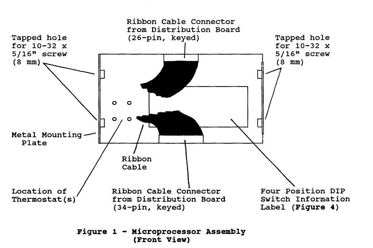
Microprocessor Assembly
(Part Number 7610251)
INSTALLATION INSTRUCTIONS
Table of Contents
1.GENERAL ........................…………………………………………………………………………. 1
2.DESCRIPTION ......................……………………………………………………………………... 1
|
Introduction......................………………………………………………………………………. |
1 |
|
Unpacking.......................……………………………………………………………………… |
2 |
|
Materials/Tools Required |
2 |
3. |
MICROPROCESSOR ASSEMBLY .............…………………………………………………….. |
5 |
|
Dip Switch Settings |
5 |
4. |
CTX GEMINI OVENS ...................………………………………………………………………. |
8 |
|
Microprocessor Assembly Removal |
8 |
|
Microprocessor Assembly Installation |
11 |
|
Thermostat Wiring |
12 |
5. |
CTX HEARTH BAKE And TRIPHASE OVENS .......………………………………………….. 13 |
|
|
Microprocessor Assembly Removal |
13 |
|
Microprocessor Assembly Installation |
15 |
Part Number 2402283
1/93
i
Microprocessor Assembly
(Part Number 7610251)
INSTALLATION INSTRUCTIONS
1. GENERAL
1.01The following provides instructions for the conversion from
Microprocessor Assembly (Part Number 7610007, 7610126, and all previous boards) to the new Microprocessor Assembly (Part Number 7610251).
1.02The CTX Microprocessor Assembly (Kit ACSKDZSTRAP) includes:
Part |
# |
7610251 |
CTX Microprocessor Assembly |
Part |
# |
3006500 |
Wrist Grounding Strap (Disposable) |
Part |
# |
2402283 |
Installation Instructions |
1.03The Microprocessor Assembly, Part Number (PN 7610251), is
installed into the following CTX Gemini, Hearth Bake, or Triphase Ovens:
CTX Gemini |
|
Hearth Bake |
|
Triohase |
DZ33 |
HB4 |
|
Z30 |
|
DZ33II |
HB4 (Menu Select) |
|
Z40 |
|
DZ33II (Menu Select) |
HB6 |
|
Z60 |
|
DZ55 |
HB6 (Menu Select) |
|
|
|
DZ55II |
|
|
|
|
DZ55II (Menu Select) |
|
|
|
|
2. DESCRIPTION
Introduction
2.01The Microprocessor Assembly consists of electrical connectors,
a 4-position DIP Switch, and related circuitry to provide control |
and interface |
||
between the keypad |
assembly and various functional areas of an oven. |
The |
Microprocessor |
Assembly is mounted |
to a metal plate which provides mounting facilities. |
A Label affixed to |
|
the Metal Mounting Plate shows the related oven models and indicates DIP Switch toggle positions. Refer to Figures 1 and 2.
Part Number 2402283
1/93
1

2.02The conversion process consists of:
•Accessing the oven control compartment.
•Disconnecting associated wiring and removing the earlier version Microprocessor Assembly.
• |
Setting the appropriate DIP-Switches on the new Microprocessor |
|
Assembly. |
•Installing The Microprocessor Assembly into the oven.
When the Microprocessor Assembly has been installed, the oven should be checked for desired operation.
Unpacking
2.03The Microprocessor Assembly was checked before leaving the
factory. Inspect the shipping container carefully for evidence of improper
handling during shipment. In case of damage, make an immediate claim to the dealer or distributor from whom the unit was purchased. If the Microprocessor Assembly was shipped to you, notify the carrier without delay and file a claim.
CAUTION
Before removing the Microprocessor Assembly from the anti-static bag, attach the static strap to your wrist and a good ground.
Materials/Tools Required
2.04The following provides a list of Materials/Tools required for the installation of the
Microprocessor Assembly:
Disposable Ground Wrist Strap (Part Number 3006500)
(the disposable wrist strap is included in the Microprocessor
Assembly) Flat blade screwdriver 5/16" (8 mm) open-end wrench Appropriate
Installation/Technical documentation on the particular oven requiring conversion.
2
3

(Rear View)
Figure 2 - Ribbon Cable Connections Between Microprocessor Assembly And
Keypad Assembly |
(Rear View) |
4
3. MICROPROCESSOR ASSEMBLY
Dip Switch Settings
3.01 The following provides instructions for keypad identification, oven identification, and DIP Switch settings:
Step Procedure
1.Open the shipping carton. Attach the supplied electrostatic discharge wrist-strap to a good ground. This prevents equipment damage caused by static discharge.
2.Remove the Microprocessor Assembly from the shipping carton and anti-static bag. Use the open shipping carton or a
Static Mat as a clean reduced-static work area to place the Microprocessor Assembly.
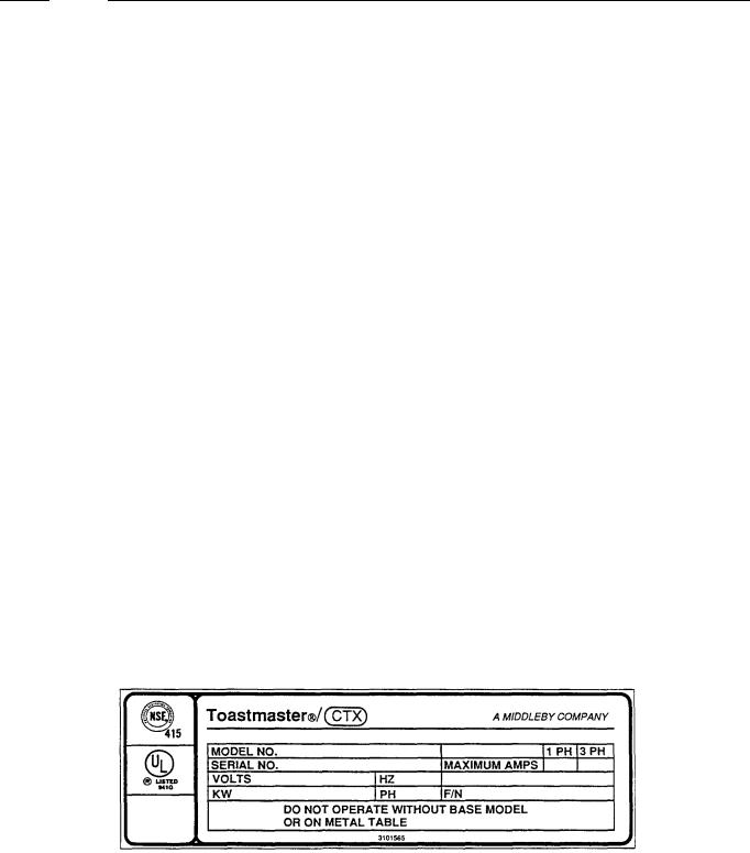
3.Refer to the Data Plate on the oven and note the Model Number. Refer to Figure 3.
4.Refer to the keypad used on the oven. On the lower portion of the keypad is printed Menu Select (late version) or it is blank (non-Menu Select, early version). This indicates the type of keypad used. Refer to Figure 4.
5.The keypad identification and oven model number are used to identify the appropriate DIP Switch and related settings.
6.Refer to the DIP Switch Setting Information Label on the Microprocessor Assembly and identify the specific oven Model and associated DIP Switch setting. (Figure 5).
7.Place the Microprocessor Assembly with the component side facing up. Locate the 4-position DIP Switch (Figure 5).
8.Set each switch to the correct position as shown on the Switch Setting Information Label.
9.For Installation information into:
A.CTX Gemini (DZ) Ovens, refer to Paragraph 4.01.
B.CTX Hearth Bake (HB) and Triphase Ovens, refer
to Paragraph 5.01.
Figure 3 – Oven Data Plate
5
 Loading...