

Page 1
EIPR
Skorpion IP Router for Automation Systems
Installation Guide
The EIPR provides Ethernet-to-Ethernet routing between a wide-area-network (WAN)
and a four-port 10/100 Mbps Ethernet switch on the local-area-network (LAN) side.
Each port automatically negotiates data rate, sets flow control and uses the Auto-MDIX
function for attaching local devices.
In some instances the EIPR will provide plug-and-play operation. By default, the router
receives an IP address assignment for its WAN port via the built-in DHCP client while a
DHCP server provides IP address assignments to LAN connected devices. A built-in
DNS forwarder will pass DNS requests from a LAN host to the remote DNS server
(through the EIPR WAN port). This allows you to install the EIPR with no configuration
unless required for advanced routing features — or when non-default operating
parameters are required. In these cases the default EIPR behaviour can be modified
via its built-in web server located at 192.168.92.1.
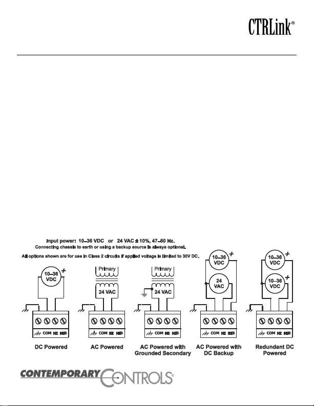
Powering. An internal half-wave rectifier allows sharing a common AC power source
with other half-wave devices. Voltage must deliver current commensurate with 6 VA
power consumption. Power conductors should be 16–22 AWG (solid) or 16–18 AWG
(stranded). Common is connected to 0 V. Chassis is isolated from 0 V. Inputs are
reverse-polarity protected.
Page 2
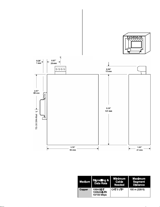
(All other pins are unused.)
Mechanical
Specifications
Environmental
Operating Temp: 0°C to +60°C
Storage Temp: –40°C to +85°C
Humidity: 10–95%, non-condensing
DIN-rail Mounting TS-35
Regulatory Compliance
CE Mark; CFR 47 Part 15, Class A
UL508 Industrial Control Equipment
Functional
Compliance: ANSI/IEEE 802.3
Data Rates: 10 and 100 Mbps
Signalling: 10BASE-T and
100BASE-TX
RJ-45 Pin Assignments
Pin Function
1 TD+
2 TD–
3 RD+
6 RD–
LED Indicators
The ―PWR‖ LED glows solid green when the unit is properly powered. LED ―L‖ for port 2
glows solid if a link exists, flashes for activity and shows data rate by colour: green for 100
Mbps or yellow for 10 Mbps. For full-duplex, the ―D‖ LED is green; for half-duplex it is unlit
but flashes if a collision occurs. The other port LEDs are unlabeled but work the same.
Network Connections
Auto-MDIX allows connections to other
equipment with either crossover or with
straight-through cabling.
Page 3

Initial Access Setup. When first installing the EIPR, its default address could
match that of a device on the Ethernet LAN and its DHCP server could interfere with
your existing LAN devices. So the EIPR and the PC used for setup should both be
temporarily disconnected from the existing LAN. The procedure for altering the IP
address creates a temporary LAN composed of nothing but the EIPR, the PC used to
configure it and a CAT5 cable connecting the two. Either straight-through or crossover
cable can be used because the EIPR supports Auto-MDIX.
Initial Access. Your EIPR will provide a DHCP assigned IP address to your PC.
Connect the PC directly to one of the LAN ports of the EIPR. Do not connect any other
devices to any of the other EIPR ports at this time. On your PC, access Network
Connections, then open the Properties of the Local Area Connections. Once the
Properties pop-up opens, scroll down under the General tab and select Internet
Protocol (TCP/IP). When the next pop-up opens, choose Obtain an IP address
automatically. Now close the opened pop-ups, and under System Accessories, open a
Command Prompt window and type ipconfig to confirm that your change of IP address
was successful. Remember to restore your PC’s original IP/Subnet values when you
are finished setting up the EIPR.
Initial Login. When the EIPR is first powered up, or after using the Reset button, the
setup screen will be accessible from one of the LAN ports using the IP address
192.168.92.1 and a subnet mask of 255.255.255.0. In the login screen that appears,
use the default value of admin for both the Username and Password.
Setup Tab. After login, the Setup screen appears. In both the WAN and LAN
portions of the screen, set the desired values as per the resident instructions.
Administration Tab. On this screen it is recommended that you choose your own
values of Username and Password.
Status Tab. This screen displays Firmware Version, MAC Address, WAN Status
and LAN Status (including the resident DHCP server and its LAN clients, if enabled).
Advanced Tab. Here you can select and adjust the advanced features of the router
as explained in the resident help screens.
Reset Switch. The Reset Switch (located just below the Power LED) will restore
factory default settings including the IP address, netmask and subnet settings. To reset
the router to its default values, use a paperclip or similar tool to press the Settings
Reset button for at least 3 seconds while the router is powered. Then release the reset
button and remove power from the router for 3 seconds. Restore power and the unit
will now use the default IP values and the default Username and Password.
Remember, upon reset, the issues mentioned above in the paragraph that is titled
Initial Access will apply!
Page 4

Need More Help Installing this Product?
More information can be found in the Technical Support part of our web site
at www.ccontrols.com. If contacting our office, ask for Technical Support.
Warranty
Warranty information can be found at the URL below:
www.ccontrols.com/warranty.htm
Warning: This is a Class A product. In a domestic environment this product may cause
radio interference in which case the user may be required to take adequate measures.
Returning Products for Repair
Return the product to the location where it was purchased by following the
instructions at the URL below:
www.ccontrols.com/rma.htm
Declaration of Conformity
Information about the regulatory compliance of this product can be found at
the URL below:
www.ccontrols.com/compliance.htm
December 2011 TD070800-0IC
 Loading...