

Page 1
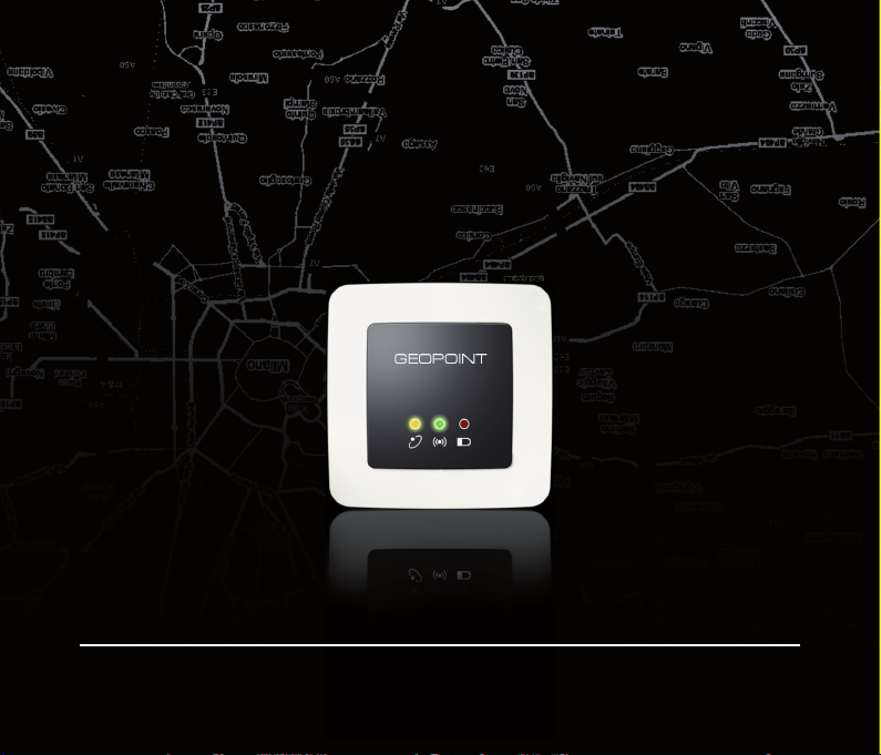
User Guide
GEOPOINT BOX
PERSONAL TRACKER
User Guide
Page 2
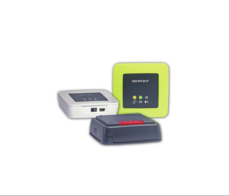
GEOPOINT BOX
PERSONAL TRACKER
User Guide
July Edition 2009
Page 3
Limitation of Liability
The Manufacturer reserves the right to modify the devices or the device specifi cations in this manual without prior notice. Any copy of this manual,
in part or in full, whether by photocopy or by other means, even of electronic nature, without the manufacture giving written authorisation, breaches
the terms of copyright and is liable to prosecution.
It is absolutely forbidden to use the device for different uses other than those for which it has been devised for, as inferred to in this manual. When
using the features in this device, obey all laws and respect privacy and legitimate rights of others.
EXCEPT TO THE EXTENT PROHIBITED BY APPLICABLE LAW, UNDER NO CIRCUMSTANCES SHALL THE MANUFACTURER BE LIABLE FOR
CONSEQUENTIAL DAMAGES SUSTAINED IN CONNECTION WITH SAID PRODUCT AND THE MANUFACTURER NEITHER ASSUMES NOR
AUTHORIZES ANY REPRESENTATIVE OR OTHER PERSON TO ASSUME FOR IT ANY OBLIGATION OR LIABILITY OTHER THAN SUCH AS IS
EXPRESSLY SET FORTH HEREIN.
All trademarks in this manual are property of their respective owners.
The information contained in this manual is for information purposes only, is subject to changes without previous notice and cannot be considered
binding for the Manufacturer. The Manufacturer assumes no responsibility for any errors or incoherence possibly contained in this manual.
Printed in Italy.
Note for the users of appliances
According to the article 13 of the Legislative Decree no. 151 dated July 25, 2005, “Enforcement of the 2002/95/EC and
2003/108/EC directives, relavant to the reduction of dangerous substances in electric and electronic applinaces, as well
as waste disposal”, the symbol of a crossed dustbin applied on appliances or on their cases means that the product at
the end of its life cycle must be disposed in a dedicated location than other waste.
The user must, therefore, dispose the aplliance at its end-of-life in the relevant disposal site for electric and electronic waste or
give it back to resellers at the time of purchasing a news equivalent one.
The correct disposal and consequant start up of a recycling of the unused appliance, treatment and fi nal disposal compatible
to the enviroment concurs to avoid possible negative effects on the enviroment and health and favours the reusing and / or
recycling of the parts making the apparatus.
The abusive disposal of such products done by users is fi ned according to the present legislation.
Page 4

Contents
Safety Instructions ................................................................................................................................... 5
General Information .................................................................................................................................6
Preliminary Procedures ..........................................................................................................................8
Inserting the SIM Card .................................................................................................................... 8
How to Charge the Battery ............................................................................................................. 9
Use of the Tracker ..................................................................................................................................10
LED Indicators ................................................................................................................................. 10
SOS Key ............................................................................................................................................ 12
Position Data and Events Recording .........................................................................................13
Tracker Management by SMS ............................................................................................................14
Position Request ............................................................................................................................. 14
Automatic Position Sending ......................................................................................................... 14
Anchor ............................................................................................................................................... 15
Geofence .......................................................................................................................................... 16
Alarm SMS ........................................................................................................................................ 17
Reading and Writing SMS Commands......................................................................................19
Page 5

Setup by MyTrack Software ................................................................................................................ 26
Power Save Mode...........................................................................................................................26
Alarm SMS ........................................................................................................................................ 29
Position Data Recording ...............................................................................................................30
Update of the Tracker Firmware Version................................................................................... 31
Maintenance ............................................................................................................................................ 32
Technical Features ................................................................................................................................. 33
Manufacturer’s Limited Warranty ...................................................................................................... 34
Warranty Period ...............................................................................................................................34
Page 6

Safety Instructions
Safety Instructions
Please read the following safety instructions carefully. Not following them may be dangerous and/or illegal. For
further details, please read carefully the user manual complete version contained in the enclosed CD ROM.
Do not switch the device on when prohibited or whenever it could cause any interference or danger. •
Obey all local laws. Always keep your hands free to operate the vehicle while driving. Your fi rst •
consideration while driving should be road safety.
All wireless devices may be susceptible to interference, which could affect the performance of other •
appliances (TV, radio,...).
Switch the device off in hospitals or near medical equipment (hearing aid equipment, pacemaker, ...) the •
device could cause interference. Always keep a distance of 20 cm between pacemaker and device.
Wireless and digital devices can cause interference with aircraft equipment.•
Do not use the device at a refuelling point. Switch-off when near petrol stations or fuel depots and chemical •
plants. The device could interfere with the correct functioning of the electronic equipment.
Do not use the device where blasting is in progress.•
Do not use the device for any uses other than those it has been built for. Keep to the instructions as •
explained in the product manual.
Only qualifi ed personnel may install or repair this product.•
Use only approved accessories and batteries. Do not use incompatible products. The use of nonstandard •
products can cause damage to device and/or people.
The batteries must be disposed according to the appropriate modes. The consumer must duly hand in •
worn out batteries, either at the appropriate collection points for the general public, in his own town, or
wherever batteries of the same kind are sold (compulsory warning according to law on the disposal of
batteries).
The device is not water-resistant, keep it dry. Contact with water or any other liquid could cause serious •
damage to the device.
5
Page 7
General Information
General Information
The tracker is a portable device able to transmit its geographical location to a mobile phone or PC in realtime and to send SOS messages in case of an emergency. Moreover, the detected data can be recorded for
further analysis.
The tracker is available in two different versions:
LCD• : GPS tracker with display, phone and 2MB data storage memory.
BOX• : GPS tracker without display, without vocal communication and with 512kB data storage memory.
Both trackers can be offered combined in the KIT version, particularly indicated for the use of Finder function,
useful for real-time locating.
This User Guide describes the tracker in the BOX version.
The tracker has two basic version:
locating and transmitting its actual position•
sending an SOS message in case of an emergency•
The tracker is provided with MyTrack software allowing the tracker management and personal tracking.
The GPS receiver and the GSM device work at higher radio frequencies which can be stopped
by enclosures containing metal and plastic parts. It is suggested to keep the tracker
under light clothes, as external as possible.
Examples of shielding materials: kevlar, carbon fi bre, some polyurethanic and polyamidic resins
especially if black, etc.
Examples of materials which cannot infl uence the radio waves: ABS, ABS+PC, policarbonate,
etc.
For further details on tracker use and functions, please read carefully the user
manual complete version contained in the enclosed CD ROM.
6
Page 8
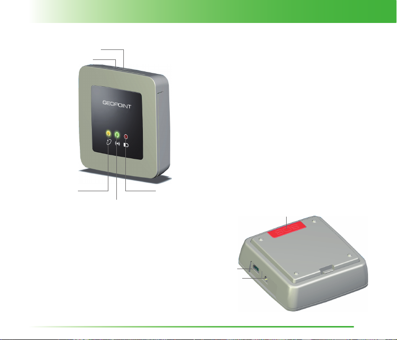
ON/OFF
BUZZER
General Information
YELLOW LED
(GPS)
GREEN LED
(GSM)
RED LED
(BATTERY)
SOS KEY
USB
DC IN
7
Page 9
Preliminary Procedures
Preliminary Procedures
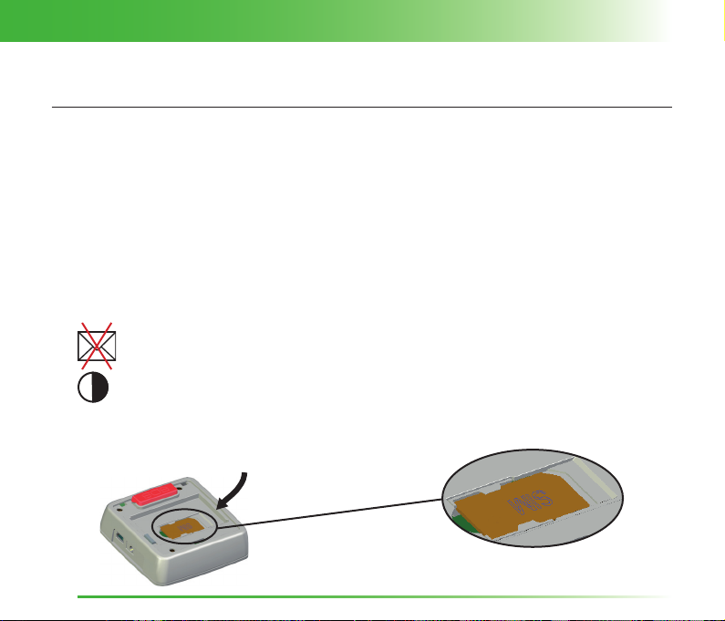
Inserting the SIM Card
In case of a SIM card:
prepaid• : the communication between the tracker and the provided software is made exclusively by SMS
text or GPRS network.
with subscription• : the communication between the tracker and the provided software is made by
SMS text, GPRS network or also sending/receiving data (only if the data number has been activated by
the network provider).
PIN: - - - - - Before inserting the SIM card in the tracker, disable the PIN code by means
30 sec.
To insert the SIM card, remove the back cover and lifting out the battery.
of a mobile phone.
Inserting a SIM card any SMS message, contained in it or which will be
received in the future, will be deleted and cannot be retriveable.
If the battery is not inserted within 30 seconds, the date and hour settings
will be ERASED.
8
Page 10
Preliminary Procedures
How to Charge the Battery
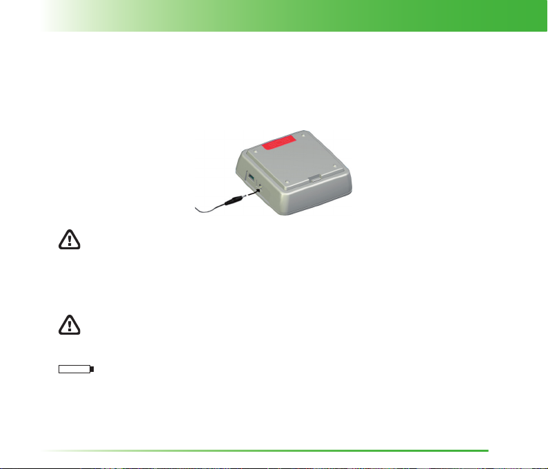
Before using the tracker for the fi rst time, the battery must be completely charged.
Before charging, check that the network electrical supply corresponds to that of the battery charger. Do not
exceed the network voltage indicated on the battery charger.
Use only batteries and battery chargers with the following features:
Battery: model ABL-6C Li-ion•
Battery charger: model ZD050050EU•
Car charger: model ESC-004•
The manufacturing company is not liable for any damage to the tracker
due to the use of accessories different from those expressly indicated.
Do not leave the tracker in particularly hot or cold environments during the
battery charging. Keep the tracker between -10°C and +40°C environmental
temperature.
When the battery is almost discharged, the tracker, if ON, emits an acoustic
warning every minute.
9
Page 11
Safety InstructionsUse of the Tracker
Use of the Tracker
LED Indicators
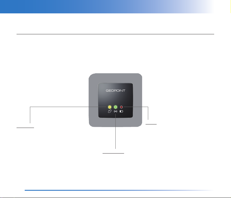
The LED indicators on the front part of the device shows the status of the main functions of the tracker. At
tracker switching on/off, the 3 LEDs will light up together at the same time for 1 second and an acoustic signal
will be emitted.
GPS Signal
OFF • T tracker off or GPS receiver off
ON • T waiting GPS signal
blinks every sec. • T poor signal level (2D FIX)
blinks every 4 sec. • T high signal level (3D FIX)
10
Battery
OFF • T tracker off or battery completely
charged
blinks every 2-3 sec. • T battery discharged
ON • T battery charging in progress
GSM Network
OFF • T tracker off or connected to USB port
blinks every sec. • T network search in progress
blinks every 4 sec. • T suffi cient signal strength
2 blinks every 4 sec. • T GSM/GPRS data communication
in progress
Page 12
Safety Instructions
Use of the Tracker
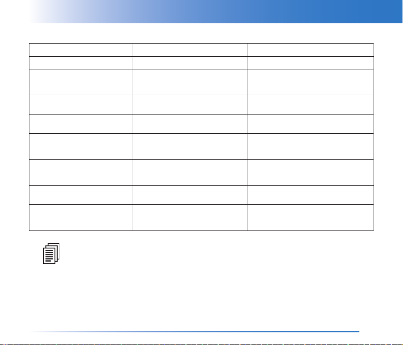
Tracker Function Description Refer to
SOS key
Position Request
Automatic Position Sending
Position Data Recording
Geofence
Anchor
Power Save Mode
Alarm SMS
the tracker sends an alarm message chapter Use of the Tracker
the tracker sends an SMS containing
its position to the phone number which
requested this data
the tracker sends automatically its position
by SMS or by GPRS connection
the tracker records its position data to
review the track afterwords
the tracker sends an alarm SMS to the
preset phone number everytime it exits or
ri-enters in a preset rectangular area
the tracker sends an alarm SMS to the
preset phone number everytime it exits or
ri-enters in a preset circular area
the tracker switches on/off automatically to
optimize the battery consumption
the tracker sends alarm SMS to the preset
phone number everytime a status change
happens (low battery, memory full, ...)
chapter Tracker Management by SMS
chapter Tracker Management by SMS
chapter Use of the Tracker
chapter Setup by MyTrack Software
chapter Tracker Management by SMS
chapter Tracker Management by SMS
chapter Setup by MyTrack Software
chapter Tracker Management by SMS
chapter Setup by MyTrack Software
The tracker can work without the SIM card. In this case, all functions operating
with GSM/GPRS network will not be available.
11
Page 13
Safety InstructionsUse of the Tracker
SOS Key
By pressing the SOS key for at least 2 seconds, for 5 consecutive times every minute, an SMS message is
immediately sent to the preset phone numbers (max. of 4 phone numbers). This message also contains the
current data on the location, if the GPS signal has been revealed. If there is no GPS signal coverage, the last
position data will be sent.
If no numbers have been set or in the absence of GSM signal, every time the
SOS key is pressed, an acoustic warning signal is emitted.
In the event that there is no network service coverage, the alarm functions
GSM
may not be available.
Example of the SMS message displayed on the mobile phone, with the detected current position data
GEO,ID:GLORIA,SOS ALARM,POS:45g37.9480N,008g28.9992E,ALT:0218m,07/04/10,10:09
Example of the SMS message displayed on the mobile phone, with the last position data detected
before the GPS signal loss
GEO,ID:GLORIA,SOS ALARM,LAST POS:45g37.9480N,008g28.9992E,ALT:0218m,07/04/10,10:09
The SMS message structure of the SOS function is described here below:
GEO Tracker type.
ID:−−−−−− Tracker name preset by the user through the provided software.
SOS ALARM Alarm message.
POS:−−−−−.−−−−−,−−−−−.−−−−− Latitude and longitude of the geographical position.
ALT:−−−−− Altitude in m.
−−/−−/−− −−:−− Event date and time (yy/mm/dd hh:mm).
12
Page 14

Safety Instructions
Use of the Tracker
Position Data and Events Recording
The tracker allows to record:
the detected events automatically without setting the recording•
the position data to review the track afterwords, if the recording was previously set•
The tracker can records approx. 14,800 position points and approx. 1,900 events.
When an event occurs, the tracker detects it and start to record in the Event LOG.
The following list shows all the events which can be detected and recorded automatically by the tracker.
power on/off•
low battery•
receiving a data call•
making a GPRS call•
hanging up a call•
motion on/off•
GSM network available/unavailable•
GPS signal available/unavailable•
entry/exit from Geofence area•
entry/exit from Anchor area•
fi rmware update•
SOS alarm•
memory erasing•
roaming on/off•
network GSM provider changing if roaming on•
The setup of the position points recording can be carried out by means of the provided software (refer to the
chapter Setup by MyTrack Software).
13
Page 15
Safety InstructionsTracker Management by SMS
Tracker Management by SMS
Position Request
It is possible to ask for the tracker position by means of an SMS command. After receiving the SMS command,
the tracker sends a message containing the position data to the phone number which sent the command.
To know the tracker position in real time, send the following command:
For further details, refer to the paragraph Reading and Writing SMS Commands.
Automatic Position Sending
The tracker can send its own position at a programmable rate. The automatic position sending can be carried
out in two different modes:
by SMS•
by GPRS connection•
CYCLIC POSITION SMS
The tracker can send an SMS message at intervals, containing all the information on its current position. This
function is useful for monitoring the tracker motion at a distance by a mobile phone.
To use this function, it is necessary to:
set, using the provided software, the phone number where the position messages will be sent•
set the rate for the cyclic position SMS using the provided software or sending an SMS command•
enable the function using the provided software or sending an SMS command•
rpos
14
Page 16

Tracker Management by SMS
CYCLIC GPRS CONNECTION
The cyclic GPRS connection allows to connect the tracker automatically at a programmed rate for the
continuous position updating. At the programmed rate, the tracker will be connected only for the time needed
for sending the position point. This function is very useful if combined with the I-Scout web server as it allows
to display the detected positions by every station connected to internet.
To use this function, it is necessary to:
set the GPRS communication parameters using the provided software or sending an SMS command•
enable the function setting the rate for cyclic GPRS connection using the provided software•
Safety Instructions
Anchor
The Anchor function allows to monitor within a pre-established circular area the position of a person, an object
or an animal. When the tracker detects the exiting from the pre-established area or the ri-entering, it sends an
alarm SMS containing its position data to the preset phone number.
This function is programmable using the complete SMS command (enabling and radius setting) or partially
by the provided software.
When the complete SMS command is received by the tracker (e.g. wanc=1,0500), the function is enabled and
the current tracker position is considered as area central point. If the function is enabled without setting the
radius, the previously set coordinates for the central point and the last programmed radius will be considered.
If no radius was previously programmed, by default it will be set to 100 m.
This function is programmable completely by SMS command (wanc). By the provided software, only function
enabling and radius setting is possible.
Before enabling this function, it is necessary to set the phone number where
SMS will be sent by means of the provided software.
15
Page 17

Safety InstructionsTracker Management by SMS
Example of the SMS message displayed on the mobile phone, when the tracker enters the area
GEO,ID:GLORIA,ANCHOR ENTER,POS:45g37.9481N,008g28.9992E,ALT:0218m,07/04/10,10:09
Example of the SMS message displayed on the mobile phone, when the tracker exits the area
GEO,ID:GLORIA,ANCHOR EXIT,POS:45g37.9481N,008g28.9992E,ALT:0218m,07/04/10,10:09
The SMS message structure of the Anchor function is described here below:
GEO Tracker type.
ID:−−−−−− Tracker name preset by the user through the provided software.
ANCHOR ENTER Alarm message.
POS:−−−−−.−−−−−,−−−−−.−−−−− Latitude and longitude of the geographical position.
ALT:−−−−− Altitude in m.
−−/−−/−− −−:−− Event date and time (yy/mm/dd hh:mm).
Geofence
The Geofence function allows to monitor the entry and the exit of the tracker in a pre-established area.
This is a rectangular area and can be programmed by set the area diagonal coordinates by means of the
provided software, or by means of an SMS command sent by a mobile phone.
To set the SMS command, refer to the paragraph Reading and Writing SMS Commands.
After having set the parameters of the Geofence function, the tracker will send an SMS message of alarm to
the preset phone number (set by means of the provided software) each time it enters/exits the pre-established
area or each time it is switched on outside the pre-established area.
16
Page 18

Tracker Management by SMS
Example of SMS message displayed on the mobile phone, when the tracker enters the area
GEO,ID:GLORIA,GEOFENCE ENTER,POS:45g37.9481N,008g28.9992E,ALT:0218m,07/04/10,10:09
Example of the SMS message displayed on the mobile phone, when the tracker exits the area
GEO,ID:GLORIA,GEOFENCE EXIT,POS:45g37.9481N,008g28.9992E,ALT:0218m,07/04/10,10:09
The SMS message structure of the Geofence function is described here below:
GEO Tracker type.
ID:−−−−−− Tracker name preset by the user through the provided software.
GEOFENCE ENTER Alarm message.
POS:−−−−−.−−−−−,−−−−−.−−−−− Latitude and longitude of the geographical position.
ALT:−−−−− Altitude in m.
−−/−−/−− −−:−− Event date and time (yy/mm/dd hh:mm).
Safety Instructions
Alarm SMS
The Alarm SMS are alarm messages sent (if the function has been enabled by the provided software) to a
phone number every time that:
the tracker battery is almost discharged•
the tracker memory is full•
the GPRS network is available•
the GPRS network is not available•
the GPS signal of the tracker has been lost•
the GPS signal of the tracker has been restored•
tracker motion is revealed•
the tracker motion stops•
17
Page 19
Safety InstructionsTracker Management by SMS
This function can only be programmed by means of the provided software.
Example of the SMS message displayed on the mobile phone, when the tracker battery is almost discharged
GEO,ID:GLORIA,LOW BATTERY,07/04/10,10:09
Example of the SMS message displayed on the mobile phone,when the tracker memory is full
GEO,ID:GLORIA,MEMORY FULL,07/04/10,10:09
Example of the SMS message displayed on the mobile phone, when the GPRS network is available
GEO,ID:GLORIA,GPRS OK,07/04/10,10:09
Example of the SMS message displayed on the mobile phone, when the GPRS network is not available
GEO,ID:GLORIA,GPRS OFF,07/04/10,10:09
Example of the SMS message displayed on the mobile phone, when there is GPS signal
GEO,ID:GLORIA,GPS FIX OK,07/04/10,10:09
Example of the SMS message displayed on the mobile phone, when the GPS signal has been lost
GEO,ID:GLORIA,NO GPS FIX,07/04/10,10:09
Example of the SMS message displayed on the mobile phone, when a tracker motion is revealed
GEO,ID:GLORIA,MOTION ON,07/04/10,10:09
Example of the SMS message displayed on the mobile phone, when a tracker motion stops
GEO,ID:GLORIA,MOTION OFF,07/04/10,10:09
18
Page 20
Tracker Management by SMS
The SMS message structure of the Alarm SMS function is described here below:
GEO Tracker type.
ID:−−−−−− Tracker name preset by the user through the provided software.
LOW BATTERY Alarm message.
−−/−−/−− −−:−− Event date and time (yy/mm/dd hh:mm).
Safety Instructions
Reading and Writing SMS Commands
The SMS commands allows to set or read some tracker settings. These messages can be sent by a mobile
phone or by a GSM device able to send/receive SMS (i.e. a GSM modem).
When the tracker is switched ON and there is GSM signal, it can receive any SMS command. If the tracker
receives a correct SMS command, an answer is sent to the SMS command sender.
If the message contains invalid characters, the tracker will not reply. If it contains invalid values, the tracker
will reply a message containing “COMMAND ERROR“. All commands start with the letter “r” (reading) or
“w” (writing).
Ensure that the SMS commands are written exactly as shown in the table. Any
change (space, capital letter, small letter,...) could affect the recognition of
the command.
Before enabling the sending of position SMS in cyclic mode (wposc), ensure
that the SMS phone number has been programmed.
19
Page 21
Safety InstructionsTracker Management by SMS
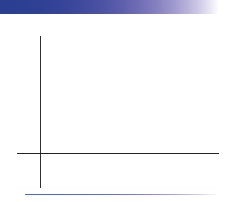
Reading Commands
Command
rpos Read instantaneous GPS position data.
The tracker can reply in 3 different ways:
A) POS: <position data> = GPS position in real
time.
B) LAST POS: <position data> = no GPS signal. The
reply message contains the last detected GPS data.
C) POS: NO GPS DATA = from the tracker switching
on, the GPS signal has not been detected.
NOTE: the date and time refer to:
rposc Read cyclic position SMS setup and power save
mode status.
[status: 0=disabled, 1=enabled]
[rate: 01÷99 minutes]
[power save mode: 0=disabled, 1=enabled]
Meaning and Values Example
SMS sending, in case of Reply A•
last detected GPS data, in case of Reply B•
20
Command: rpos
Reply A:
POS:41g37.8283N,012g28.8191E,
ALT:0262m,DIR:023g,SPEED:0050km/h,
SAT:09,07/05/26,15:56
Reply B:
LAST POS:45g37.8283N,
008g28.8191E,ALT:0262m,
DIR:023g,SPEED:0050km/h,
SAT:09,07/05/26,15:56
Reply C:
POS: NO GPS DATA
Description:
41g37.8283N Lat. in degree, min.
012g28.8191E Long. in degree, min.
0262m Altitude in m
023g Direction in degree
0050km/h Speed in km/h
09 Satellites number
07/05/26 Date (yymmdd)
15:56 Time (hhmm)
Command: rposc
Reply: rposc=1,01,0
Description:
1=enabled cyclic position SMS
01=1 minute rate
0=disabled power save mode
Page 22
Tracker Management by SMS
Safety Instructions
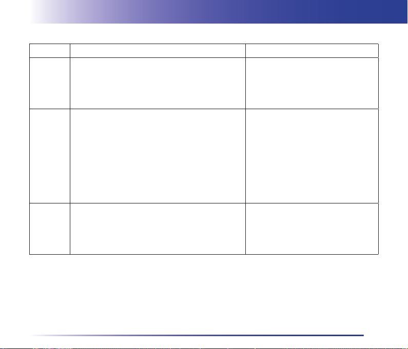
Command
rms Read the accelerometer setup values.
[sensitivity: 00=disabled sensor, 01=maximum,
10=minimum]
[timeout: 01÷99 minutes]
rgf Read the Geofence setup.
[status: 0=disabled, 1=enabled]
[LAT1,LONG1,LAT2,LONG2=latitude and
longitude of the 2 points which defi ne the Geofence
area]
ranc Read the Anchor setup.
[status: 0=disabled, 1=enabled]
[radius: 0050, 0100, 0200, 0300, 0500, 0700, 1000,
1500, 2000, 3000, 4000 m]
Meaning and Values Example
Command: rms
Reply: rms=02,10
Description:
02=sensitivity level 2
10=10 minutes timeout
Command: rgf
Reply:
rgf=1,45g37.7981N,008g28.8012E,
41g37.8971N,012g28.8012E
Description:
1=enabled
45g37.7981N,008g28.8012E=latitude
and longitude of the fi rst point
41g37.8971N,012g28.8012E=latitude
and longitude of the second point
Command: ranc
Reply: ranc=1,0100
Description:
1=enabled
0100=radius at 100 m
21
Page 23
Safety InstructionsTracker Management by SMS
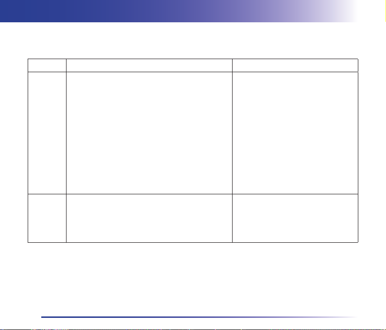
Writing Commands
Command
wposc Set the cyclic position SMS in text format and the
relevant power save mode.
[enabling: 0=disable, 1=enable]
[rate: 01÷99 minutes]
[power save mode: 0=disable, 1=enable]
NOTE: the power save mode works only with
SMS rate5 minutes.
Never set like this: wposc=0,xx,1
NOTE: to enable or disable only the cyclic position
SMS, send the wposc command with the fi rst
fi eld only. In this case, the previously set rate is
considered.
wms Set the accelerometer values.
[sensitivity: 00=disables sensor, 01=maximum,
10=minimum]
[timeout: 01÷99 minutes]
Meaning and Values Example
22
Case A
Command: wposc=1,01,0
Reply: wposc=1,01,0 OK
Description:
1=enables the cyclic position SMS
01=1 minute rate
0=disables the power save mode
Case B
Command: wposc=1
Reply: wposc=1 OK
Description:
1=enables the cyclic position SMS with
the previous set rate
Command: wms=02,10
Reply: wms=02,10 OK
Description:
02=sensitivity level 2
10=10 minutes timeout
Page 24
Tracker Management by SMS
Safety Instructions
Command
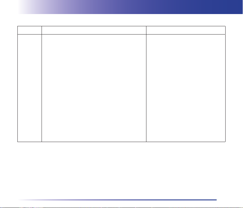
wgf Set the Geofence.
[status: 0=disable, 1=enable]
[LAT1,LONG1,LAT2,LONG2=latitude and longitude
for the 2 points defi ning the Geofence area]
NOTE: to enable or disable the Geofence function
without setting the area, sent the wgf command with
the fi rst fi eld only.
Meaning and Values Example
Case A
Command:
wgf=1,45g37.7981N,008g28.8012E,
41g37.8971N,012g28.8012E
Reply:
wgf=1,45g37.7981N,008g28.8012E,
41g37.8971N,012g28.8012E OK
Description:
1=enable
45g37.7981N,008g28.8012E=latitude
and longitude of the fi rst point
41g37.8971N,012g28.8012E=latitude
and longitude of the second point
Case B
Command: wgf=1
Reply: wgf=1 OK
Description:
1=enables the function considering the
previous defi ned area
23
Page 25
Safety InstructionsTracker Management by SMS
Command
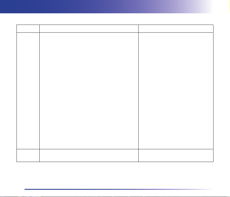
wanc Set the Anchor.
[enabling: 0=disable, 1=enable]
[radius: 0050, 0100, 0200, 0300, 0500, 0700, 1000,
1500, 2000, 3000, 4000 m; default radius: 0100]
NOTE: to set the tracker current position as area
center point, send the complete wanc command,
containing both enabling and radius fi elds (e.g.
wanc=1,0100).
NOTE: to enable or disable the Anchor function
without setting the radius, send the wanc command
with the fi rst fi eld only. In this case, the default radius
or the previously set radius is considered.
wem Erase all position data recorded in the memory. Command: wem
Meaning and Values Example
Case A
Command: wanc=1,0100
Reply: wanc=1,0100 OK
Description:
1=enables
0100=radius at 100 m
Case B
Command: wanc=1,0100
Reply: NO VALID CENTER POS
Description:
1=enables
0100=radius at 100 m
NO VALID CENTER POS=if the center
point cannot be detected
Case C
Command: wanc=1
Reply: wanc=1 OK
Description:
1=enables the function considering
the default radius or the previously set
radius
Reply: wem OK
24
Page 26

Tracker Management by SMS
Safety Instructions
Command
wgprs Set the GPRS parameters and start the continuous
GPRS connection.
[setup: 0=set the GPRS parameters without starting
the connection,
1=connect with the new parameters (IP, PORT),
2=connect with the parameters previously preset]
[parameters: IP=host IP address, PORT=TCP port]
NOTE: the IP and PORT parameters should be
written between commas.
NOTE: if there is no GPRS connection, the tracker
sends an error SMS containing “GPRS ERROR”.
Meaning and Values Example
Case A
Command:
wgprs=0,”213.86.89.11”,”9500”
Reply:
wgprs=0,”213.86.89.11”,”9500” OK
Description:
0=set GPRS parameters without
starting the connection
213.86.89.11=host IP address (example)
9500=TCP port
Case B
Command:
wgprs=1,”213.86.89.11”,”9500”
Reply:
wgprs=1,”213.86.89.11”,”9500” OK
Description:
1=GPRS connection with new parameters
213.86.89.11=host IP address (example)
9500=TCP port
Case C
Command: wgprs=2
Reply: wgprs=2 OK
Case D
Reply: NO GPRS COVERAGE
Description:
NO GPRS COVERAGE=if GPRS signal
is missing
25
Page 27
Safety InstructionsSetup by MyTrack Software
Setup by MyTrack Software
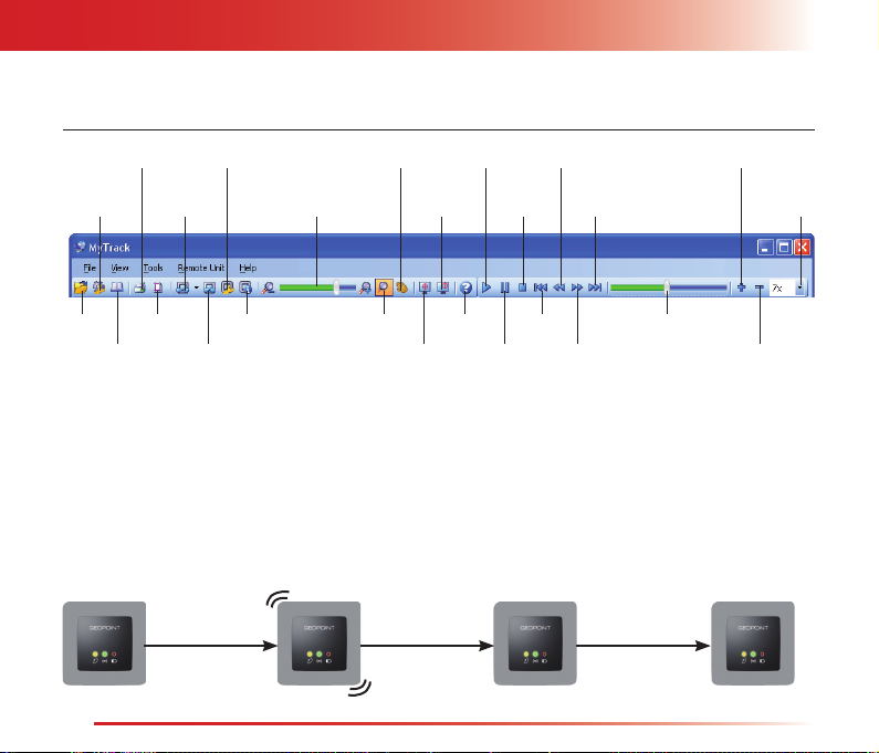
INCREASE THE
RECORDING
BAR TO SCROLL
RECORDING
THE
MYTRACK
SETUP
OPEN
ADDRESS BOOK
PRINT
CONNECT
PAGE SETUP
GEOPOINT
SETUP
INFORMATION
DISCONNECT
ZOOM
BAR
ZOOM
PAN
FOLLOW
CENTER
HELP
PLAY
PAUSE
STOP
REWIND
LAST
FIRST
FORWARD
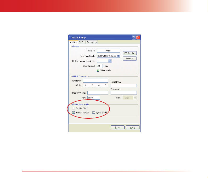
Power Save Mode
The Power Save Mode allows for optimal management of the battery tracker. It is possible to set the tracker
automatic switching on/off according to specifi c use requirements.
There are three Power Save Modes programmable by means of the provided software, except for Cyclic
Position SMS which is programmable by SMS command too. After Power Save Mode enabling, the tracker will
switch off automatically 2 minutes after tracker disconnection by the provided software.
WITH MOTION
OFF ON
MOTION
NO MOTION FOR A
PRESET TIME, NO DATA
EXCHANGE
SPEED
RECORDING
DECREASE THE
RECORDING
OFF
SPEED
SPEED
26
Page 28
Setup by MyTrack Software
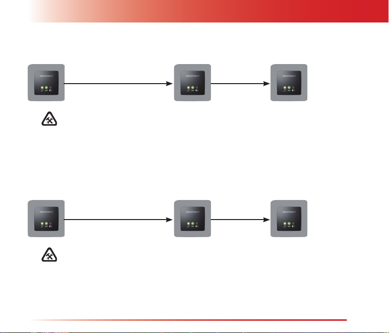
WITH CYCLIC POSITION SMS
OFF ON OFF
CYCLIC POSITION SMS SENDING SMS SENT
Before using this mode, enable and set the Cyclic Position SMS function with
SMS rate 5 minutes.
During the automatic switching on, if the tracker is connected by the provided software, the automatic
switching off will be carried out after position SMS sending, after carrying out all the preset operations and 2
minutes after tracker disconnection.
WITH CYCLIC GPRS CONNECTION
OFF ON OFF
CYCLIC GPRS CONNECTION
Before using this mode, enable and set the Cyclic GPRS Connection function
with rate 5 minutes.
The tracker will switch off automatically after successfull GPRS connection and after carrying out all the preset
operations.
If, after two tries, the GPRS connection is failed, the tracker will switch off automatically.
Safety Instructions
27
Page 29
Safety InstructionsSetup by MyTrack Software
To a set a Power Save Mode, connect the tracker to the provided software and access the setup window by
selecting Setup from Remote Unit menu.
28
Page 30
Setup by MyTrack Software
Safety Instructions
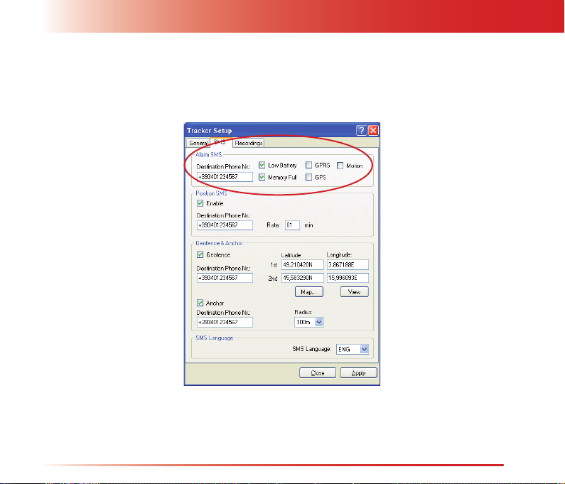
Alarm SMS
To enable/disable the Alarm SMS and set the phone number, connect the tracker to the provided software and
access the setup window by selecting Setup from Remote Unit menu.
29
Page 31
Safety InstructionsSetup by MyTrack Software
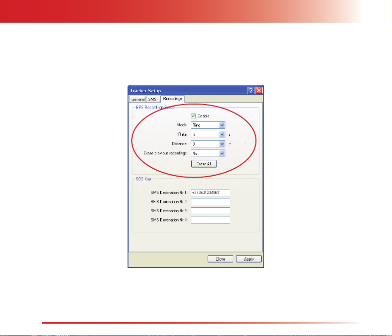
Position Data Recording
To set a data position recording, connect the tracker to the provided software and access the setup window by
selecting Setup from Remote Unit menu.
30
Page 32
Setup by MyTrack Software
Safety Instructions
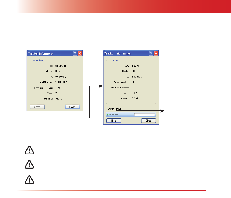
Update of the Tracker Firmware Version
To update the tracker, connect the tracker to the provided software and access the info window by selecting
Info from Remote Unit menu.
A new window is opened
for update fi le selection
The 3 LEDs remain continuously ON during tracker fi rmware update.
Wait until the update is completed, this occurs when the tracker is turned off.
If the tracker to be updated is connected with GSM/GPRS network, be sure
that the GSM/GPRS network signal level is high.
If the tracker to be updated is connected by a USB cable, do not remove the
cable during the update.
To perform the update, it is necessary to connect the provided battery charger
to the tracker.
31
Page 33
Safety InstructionsMaintenance
Maintenance
The tracker and relevant accessories must be handled with care. Read the following instructions carefully.
Clean the tracker with a soft cloth, avoiding the use of corosive chemical products, solvents or aggressive •
detergents.
Do not paint the tracker.•
Do not swallow the accessories or small components of the tracker.•
Avoid blows to the tracker which could internally damage the product.•
Do not open the tracker in any way differently from the way indicated in the manual. •
Do not wet the tracker. Humidity, condensation, rain or any other liquids containing mineral substances •
could damage the electronic circuits. In the event of contact with liquids, remove the battery and leave
the tracker to dry.
Do not use or leave the tracker in particularly hot environments. High temperatures could damage the •
electronic circuits, the battery and the plastic parts of the tracker.
Do not use or leave the tracker in particularly cold environments. Low temperatures could cause damage •
to the electronic circuit boards of the tracker.
Do not use or leave the tracker in particularly dirty or dusty environments, the tracker could get •
damaged.
32
Page 34
Safety Instructions
Technical Features
Technical Features
GPS receiver: SiRFstarIII - 20 channels
GSM frequencies: 850 / 900 / 1800 / 1900 MHz
Data memory: 512kB non-volatile FLASH
Porta di comunicazione: no.1 USB
Sensor: no.1 for accelerometer
Dimension/Weight: 74 x 74 x 23 mm / 120 gr
Battery: model ABL-6C Li-ion - 3,7V 1000mAh
Battery charger: model ZD050050EU
input 100VAC - 240V 50/60Hz 0,15A
output 5VDC 500mA
Car charger: model ESC-004
input 13,6VDC
output 5VDC 500mA
Conformity: CE mark
CONDITION BATTERY
LIFE
Standby mode with motion sensor active. ~10 days
Tracking SMS every minute (GPS always on). ~9 hours
Tracking SMS every 5 minutes (GPS with hotstart). ~4 days
Continuous tracking. ~2 hours
Data connection, with GPS system continuously active. ~2 hours
Position data recording every minute. ~37 hours
Tracker not in use. ~2 days
Tracker in communication on GSM network. ~4 hours
33
Page 35
Safety InstructionsManufacturer’s Limited Warranty
Manufacturer’s Limited Warranty
This warranty does not limit the user’s (statutory) rights under applicable national laws relating to the sale of
consumer products.
During the warranty period, the Manufacturer or Manufacturer authorized service company will in a commercially
reasonable time remedy defects in materials, design and workmanship free of charge by repairing.
The Manufacturer will, in accordance with this Limited Warranty (unless otherwise required by law), remedy
defects by repair or, should the Manufacturer in its discretion deem it necessary, replace the Product.
This Limited Warranty is only valid and enforceable in the country where the user has purchased the Product
provided that the same Product has been intended for sale in that country by the Manufacturer. However, if
the user has purchased the Product in a member state of the European Union, Iceland, Norway, Switzerland
or Turkey and such Product was originally intended by the Manufacturer for sale in one of these countries,
this Limited Warranty is valid and enforceable in all of these above listed countries. Some limitations to the
warranty service may apply because of country specifi c elements in the Products.
Warranty Period
The warranty period starts at the time of Product’s original purchase by the fi rst end-user. The Product may
consist of several different parts and different parts may be covered by a different warranty period. The
different Warranty Periods are:
24 months for the device•
6 months for the following consumable parts and accessories: battery, chargers, device cover•
90 days for the media on which any software is provided, (e.g. CD ROM, DVD,...)•
As far as national laws permit, the warranty period will not be extended or renewed or otherwise affected due
to subsequent resale, repair or replacement of the Product authorized by the Manufacturer.
34
Page 36

www.cte.it
Distributed by
www.cte.it
 Loading...