

Page 1

MSW-4424C
MSW-4424CS
L2+ Gigabit Carrier Ethernet Switch
1
Page 2

LEGAL
The information in this publication has been carefully checked and is believed to be entirely accurate at the time of
publication. CTC Union Technologies assumes no responsibility, however, for possible errors or omissions, or for any
consequences resulting from the use of the information contained herein. CTC Union Technologies reserves the right
to make changes in its products or product specifications with the intent to improve function or design at any time
and without notice and is not required to update this documentation to reflect such changes.
CTC Union Technologies makes no warranty, representation, or guarantee regarding the suitability of its products for
any particular purpose, nor does CTC Union assume any liability arising out of the application or use of any product
and specifically disclaims any and all liability, including without limitation any consequential or incidental damages.
CTC Union products are not designed, intended, or authorized for use in systems or applications intended to support
or sustain life, or for any other application in which the failure of the product could create a situation where personal
injury or death may occur. Should the Buyer purchase or use a CTC Union product for any such unintended or
unauthorized application, the Buyer shall indemnify and hold CTC Union Technologies and its officers, employees,
subsidiaries, affiliates, and distributors harmless against all claims, costs, damages, expenses, and reasonable attorney
fees arising out of, either directly or indirectly, any claim of personal injury or death that may be associated with such
unintended or unauthorized use, even if such claim alleges that CTC Union Technologies was negligent regarding the
design or manufacture of said product.
TRADEMARKS:
Microsoft is a registered trademark of Microsoft Corp.
HyperTerminal™ is a registered trademark of Hilgraeve Inc.
WARNING:
This equipment has been tested and found to comply with the limits for a Class A digital device, pursuant to Part 15 of
the FCC Rules. These limits are designed to provide reasonable protection against harmful interference when the
equipment is operated in a commercial environment. This equipment generates, uses, and can radiate radio
frequency energy and if not installed and used in accordance with the instruction manual may cause harmful
interference in which case the user will be required to correct the interference at his own expense. NOTICE: (1) The
changes or modifications not expressively approved by the party responsible for compliance could void the user's
authority to operate the equipment. (2) Shielded interface cables and AC power cord, if any, must be used in order to
comply with the emission limits.
CISPR PUB.22 Class A COMPLIANCE:
This device complies with EMC directive of the European Community and meets or exceeds the following technical
standard. EN 55022 - Limits and Methods of Measurement of Radio Interference Characteristics of Information
Technology Equipment. This device complies with CISPR Class A.
WARNING:
This is a Class A product. In a domestic environment this product may cause radio interference in which case the user
may be required to take adequate measures.
CE NOTICE
Marking by the symbol CE indicates compliance of this equipment to the EMC directive of the European Community.
Such marking is indicative that this equipment meets or exceeds the following technical standards: EN
55022:2006+A1:2007, Class A, EN55024:2010, and EN60950-1:2006
2
Page 3

2016 CTC Union Technologies Co.,Ltd.
All Rights Reserved
The contents of this document are subject to change without any prior notice.
CTC Union Technologies Co., Ltd.
Far Eastern Vienna Technology Center (Neihu Technology Park)
8F, No. 60, Zhouzi St.,
Neihu, Taipei, 114
Taiwan
Phone: +886-2-2659-1021
FAX: +886-2-2799-1355
MSW-4424C & MSW-4424CS Series
L2+ Gigabit Carrier Ethernet Switch
User Manual
Version 0.9e February 2016 (Draft)
This manual supports the following models:
MSW-4424C
MSW-4424CS
This document is the current official release manual. Please check CTC Union's website for any updated manual or
contact us by E-mail at [email protected]. Please address any comments for improving this manual or to point out
omissions or errors to [email protected]. Thank you.
3
Page 4

TABLE OF CONTENTS
CHAPTER 1. INTRODUCTION ..................................................................................................... 18
1.1 PRODUCT DESCRIPTION..................................................................................................................... 18
1.2 PANELS ......................................................................................................................................... 18
CHAPTER 2. INSTALLATION ....................................................................................................... 20
2.1 FIBER CONNECTIONS ........................................................................................................................ 20
2.2 MGMT PORT CONNECTION ............................................................................................................... 20
2.3 CONSOLE PORT CONNECTION ............................................................................................................. 20
2.3.1 RJ-45 Pin Assignment ....................................................................................................................................... 21
2.3.2 Accessory Cable ............................................................................................................................................... 21
2.4 ELECTRICAL INSTALLATION ................................................................................................................. 21
2.5 RACK MOUNTING ............................................................................................................................ 22
2.6 LED INDICATORS & RESET TO DEFAULT BUTTON ..................................................................................... 23
CHAPTER 3. INTRODUCTION TO CLI .......................................................................................... 24
3.1 INTRODUCTION ............................................................................................................................... 24
3.2 CONSOLE OPERATION ..................................................................................................................... 24
3.3 CLI MODES .................................................................................................................................... 25
3.4 QUICK KEYS ................................................................................................................................... 25
3.5 COMMAND SYNTAX ......................................................................................................................... 25
3.6 BASIC CONFIGURATIONS ................................................................................................................... 26
3.6.1 Configuring IPv4 Address ................................................................................................................................. 26
3.6.2 Enter Config Interface Mode ........................................................................................................................... 26
3.6.3 Save Configurations ......................................................................................................................................... 27
3.6.4 Restart the Device ............................................................................................................................................ 27
3.6.5 Load Factory Defaults ...................................................................................................................................... 27
3.6.6 Show System and Software Information ......................................................................................................... 27
3.6.7 Show Running Configurations .......................................................................................................................... 28
3.6.8 Show History Commands ................................................................................................................................. 28
3.6.9 Help .................................................................................................................................................................. 29
3.6.10 Logout ............................................................................................................................................................ 29
3.7 COMMANDS IN USER MODE .............................................................................................................. 29
3.7.1 > clear ip arp .................................................................................................................................................... 30
3.7.2 > clear lldp statistics ......................................................................................................................................... 30
3.7.3 > clear statistics ............................................................................................................................................... 30
3.7.4 > enable ........................................................................................................................................................... 30
3.7.5 > exit ................................................................................................................................................................ 30
3.7.6 > help ............................................................................................................................................................... 30
3.7.7 > logout ............................................................................................................................................................ 31
3.7.8 > ping ip ........................................................................................................................................................... 31
3.7.9 > ping ipv6 ........................................................................................................................................................ 31
3.7.10 show commands ............................................................................................................................................ 31
3.8 COMMANDS IN EXEC MODE .............................................................................................................. 32
3.8.1 # clear access management statistics .............................................................................................................. 32
3.8.2 # clear access-list ace statistics ........................................................................................................................ 32
3.8.3 # clear dot1x statistics ..................................................................................................................................... 32
3.8.4 # clear eps ........................................................................................................................................................ 32
3.8.5 # clear erps....................................................................................................................................................... 32
3.8.6 # clear evc statistics ......................................................................................................................................... 32
3.8.7 # clear ip arp .................................................................................................................................................... 33
3.8.8 # clear ip dhcp detailed statistics ..................................................................................................................... 33
3.8.9 # clear ip dhcp relay statistics .......................................................................................................................... 33
3.8.10 # clear ip dhcp server binding <ip> ................................................................................................................ 33
3.8.11 # clear ip dhcp server binding { automatic | manual | expired } ................................................................... 33
3.8.12 # clear ip dhcp server statistics ...................................................................................................................... 34
3.8.13 # clear ip dhcp snooping statistics ................................................................................................................. 34
4
Page 5

TABLE OF CONTENTS
3.8.14 # clear ip igmp snooping ................................................................................................................................ 34
3.8.15 # clear ip statistics .......................................................................................................................................... 34
3.8.16 # clear ipv6 mld snooping .............................................................................................................................. 34
3.8.17 # clear ipv6 neighbors .................................................................................................................................... 34
3.8.18 # clear ipv6 statistics ...................................................................................................................................... 34
3.8.19 # clear lacp statistics ...................................................................................................................................... 35
3.8.20 # clear lldp statistics ....................................................................................................................................... 35
3.8.21 # clear logging ................................................................................................................................................ 35
3.8.22 # clear mac address-table .............................................................................................................................. 35
3.8.23 # clear mep .................................................................................................................................................... 35
3.8.24 # clear mvr ..................................................................................................................................................... 35
3.8.25 # clear spanning-tree ..................................................................................................................................... 35
3.8.26 # clear statistics ............................................................................................................................................. 36
3.8.27 # config terminal ............................................................................................................................................ 36
3.8.28 # copy ............................................................................................................................................................. 36
3.8.29 # delete .......................................................................................................................................................... 37
3.8.30 # dir ................................................................................................................................................................ 37
3.8.31 # disable & # enable ....................................................................................................................................... 38
3.8.32 # dot1x ........................................................................................................................................................... 38
3.8.33 # erps ............................................................................................................................................................. 38
3.8.34 # firmware swap ............................................................................................................................................ 38
3.8.35 # firmware upgrade ....................................................................................................................................... 39
3.8.36 # ip dhcp retry interface vlan ......................................................................................................................... 39
3.8.37 # more ............................................................................................................................................................ 39
3.8.38 # ping ip ......................................................................................................................................................... 39
3.8.39 # ping ipv6 ...................................................................................................................................................... 39
3.8.40 # reload cold .................................................................................................................................................. 40
3.8.41 # reload defaults ............................................................................................................................................ 40
3.8.42 # send ............................................................................................................................................................. 40
3.8.43 # terminal editing ........................................................................................................................................... 40
3.8.44 # terminal exec-timeout ................................................................................................................................ 41
3.8.45 # terminal history size .................................................................................................................................... 41
3.8.46 # terminal length ........................................................................................................................................... 41
3.8.47 # terminal width ............................................................................................................................................ 42
3.8.48 # no port-security shutdown ......................................................................................................................... 42
3.8.49 show commands ............................................................................................................................................ 42
3.9 COMMANDS IN CONFIG MODE ........................................................................................................... 42
3.9.1 (config)# aaa authentication login ................................................................................................................... 42
3.9.2 (config)# access management ......................................................................................................................... 43
3.9.3 (config)# access-list .......................................................................................................................................... 44
3.9.3.1 (config)# access-list ace ................................................................................................................................................44
3.9.3.2 (config)# access-list ace update ....................................................................................................................................45
3.9.3.3 (config)# access-list rate-limiter ...................................................................................................................................46
3.9.3.4 (config-if)# access-list action ........................................................................................................................................46
3.9.3.5 (config-if)# access-list logging .......................................................................................................................................46
3.9.3.6 (config-if)# access-list policy .........................................................................................................................................46
3.9.3.7 (config-if)# access-list port-state ..................................................................................................................................47
3.9.3.8 (config-if)# access-list rate-limiter ................................................................................................................................47
3.9.3.9 (config-if)# access-list shutdown ..................................................................................................................................47
3.9.3.10 (config-if)# access-list {redirect| port-copy } ..............................................................................................................47
3.9.4 (config)# aggregation ....................................................................................................................................... 48
3.9.4.1 (config)# aggregation mode .........................................................................................................................................48
3.9.4.2 (config-if)# aggregation group ......................................................................................................................................48
3.9.5 (config)# banner............................................................................................................................................... 48
3.9.5.1 (config)# banner [ motd ] <banner> .............................................................................................................................48
3.9.5.2 (config)# banner exec <banner> ...................................................................................................................................49
3.9.5.3 (config)# banner login <banner> ..................................................................................................................................49
3.9.6 (config)# clock .................................................................................................................................................. 49
5
Page 6

TABLE OF CONTENTS
3.9.6.1 (config)# clock summer-time <word16> date ..............................................................................................................49
3.9.6.2 (config)# clock summer-time <word16> recurring .......................................................................................................50
3.9.6.3 (config)# clock timezone ...............................................................................................................................................50
3.9.7 (config)# default access-list rate-limiter .......................................................................................................... 51
3.9.8 (config)# dot1x ................................................................................................................................................. 51
3.9.8.1 (config)# dot1x system-auth-control ............................................................................................................................51
3.9.8.2 (config)# dot1x re-authentication ................................................................................................................................52
3.9.8.3 (config)# dot1x authentication timer re-authenticate .................................................................................................52
3.9.8.4 (config)# dot1x timeout tx-period ................................................................................................................................52
3.9.8.5 (config)#dot1x authentication timer inactivity .............................................................................................................53
3.9.8.6 (config)# dot1x timeout quiet-period ...........................................................................................................................53
3.9.8.7 (config)# dot1x feature .................................................................................................................................................53
3.9.8.8 (config)# dot1x guest-vlan ............................................................................................................................................54
3.9.8.9 (config)# dot1x guest-vlan supplicant ..........................................................................................................................54
3.9.8.10 (config)# dot1x max-requth-req .................................................................................................................................54
3.9.8.11 (config-if)# dot1x port-control ....................................................................................................................................55
3.9.8.12 (config-if)# dot1x guest-vlan .......................................................................................................................................56
3.9.8.13 (config-if)# dot1x radius-qos ......................................................................................................................................56
3.9.8.14 (config-if)# dot1x radius-vlan .....................................................................................................................................56
3.9.8.15 (config-if)# dot1x re-authenticate ..............................................................................................................................57
3.9.9 (config-if)# duplex ............................................................................................................................................ 57
3.9.10 (config)# enable ............................................................................................................................................. 57
3.9.10.1 (config)# enable password .........................................................................................................................................57
3.9.10.2 (config)# enable password level .................................................................................................................................57
3.9.10.3 (config)# enable secret ...............................................................................................................................................58
3.9.11 (config)# eps .................................................................................................................................................. 58
3.9.11.1 (config)# eps <inst> 1plus1 { bidirectional | { unidirectional [ aps ] } } .......................................................................58
3.9.11.2 (config)# eps <inst> command ...................................................................................................................................58
3.9.11.3 (config)# eps <inst> domain .......................................................................................................................................59
3.9.11.4 (config)# eps <inst> holdoff <hold> ............................................................................................................................59
3.9.11.5 (config)# eps <inst> mep-work <mep_w> mep-protect <mep_p> mep-aps <mep_aps> ...........................................60
3.9.11.6 (config)# eps <inst> revertive .....................................................................................................................................60
3.9.12 (config)# erps ................................................................................................................................................. 60
3.9.12.1 (config)# erps <group> guard <guard_time_ms> .......................................................................................................60
3.9.12.2 (config)# erps <group> holdoff <holdoff_time_ms> ..................................................................................................61
3.9.12.3 (config)# erps <group> major port0 interface port1 interface <port_type> <port1> [ interconnect ] .......................61
3.9.12.4 (config)# erps <group> mep port0 sf <p0_sf> aps <p0_aps> port1 sf <p1_sf> aps <p1_aps> ....................................62
3.9.12.5 (config)# erps <group> revertive <wtr_time_minutes> .............................................................................................62
3.9.12.6 (config)# erps <group> rpl { owner | neighbor } { port0 | port1 } ..............................................................................62
3.9.12.7 (config)# erps <group> sub port0 interface <port_type> <port0> { { port1 interface <port_type> <port1> } |
{ interconnect <major_ring_id> [ virtual-channel ] } } ..............................................................................................................63
3.9.12.8 (config)# erps <group> topology-change propagate ..................................................................................................63
3.9.12.9 (config)# erps <group> version { 1 | 2 } ......................................................................................................................64
3.9.12.10 (config)# erps <group> vlan { none | [ add | remove ] <vlans> } ..............................................................................64
3.9.13 (config)# evc ................................................................................................................................................... 64
3.9.13.1 (config)# evc [ update ] <evc_id>................................................................................................................................64
3.9.13.2 evc ece ........................................................................................................................................................................65
3.9.13.3 evc policer ..................................................................................................................................................................66
3.9.14 (config-if)# excessive-restart ......................................................................................................................... 68
3.9.15 (config-if)# flowcontrol { on | off }................................................................................................................. 68
3.9.16 (config-if)# geen-ethernet ............................................................................................................................. 68
3.9.16.1 (config-if)# green-ethernet energy-detect .................................................................................................................68
3.9.16.2 (config-if)# green-ethernet short-reach .....................................................................................................................68
3.9.17 (config)# fanmode { auto | full | low } ........................................................................................................... 69
3.9.18 (config)# gvrp ................................................................................................................................................. 69
3.9.18.1 (config)# gvrp..............................................................................................................................................................69
3.9.18.2 (config)# gvrp max-vlans ............................................................................................................................................69
3.9.18.3 (config)# gvrp time .....................................................................................................................................................70
6
Page 7

TABLE OF CONTENTS
3.9.18.4 (config-if)# gvrp ..........................................................................................................................................................70
3.9.19 (config)# hostname ........................................................................................................................................ 70
3.9.20 (config)# interface .......................................................................................................................................... 71
3.9.20.1(config)# interface ( <port_type> [ <plist> ] ) ..............................................................................................................71
3.9.20.2 (config)# interface vlan ...............................................................................................................................................72
3.9.21 (config)# ip ..................................................................................................................................................... 72
3.9.21.1 (config)# ip arp inspection ..........................................................................................................................................72
3.9.21.2 (config)# ip arp inspection entry interface .................................................................................................................72
3.9.21.3 (config)# ip arp inspection translate ...........................................................................................................................73
3.9.21.4 (config)# ip arp inspection vlan ..................................................................................................................................73
3.9.21.5 (config)# ip arp inspection vlan <in_vlan_list> logging ...............................................................................................73
3.9.21.6 (config)# ip dhcp excluded-address ............................................................................................................................74
3.9.21.7 (config)# ip dhcp pool .................................................................................................................................................74
3.9.21.8 (config)# ip dhcp relay ................................................................................................................................................74
3.9.21.9 (config)# ip dhcp relay information circuit-id format .................................................................................................75
3.9.21.10 (config)# ip dhcp relay information option ...............................................................................................................75
3.9.21.11 (config)# ip dhcp relay information policy {drop | keep |replace} ...........................................................................76
3.9.21.12 (config)# ip dhcp relay information remote-id .........................................................................................................76
3.9.21.13 (config)# ip dhcp relay information remote-id format .............................................................................................76
3.9.21.14 (config)# ip dhcp server ............................................................................................................................................77
3.9.21.15 (config)# ip dhcp snooping .......................................................................................................................................77
3.9.21.16 (config)# ip dhcp snooping table get ........................................................................................................................77
3.9.21.17 (config)# ip dhcp snooping table interval .................................................................................................................78
3.9.21.18 (config)# ip dhcp snooping table put ........................................................................................................................78
3.9.21.19 (config)# ip dhcp snooping table retransmit ............................................................................................................78
3.9.21.20 (config)# ip dhcp snooping vlan ................................................................................................................................78
3.9.21.21 (config)# ip dns proxy ...............................................................................................................................................79
3.9.21.22 (config)# ip helper-address .......................................................................................................................................79
3.9.21.23 (config)# ip http secure-server .................................................................................................................................79
3.9.21.24 (config)# ip http secure-redirect ...............................................................................................................................80
3.9.21.25 (config)# ip igmp host-proxy.....................................................................................................................................80
3.9.21.26 (config)# ip igmp snooping .......................................................................................................................................80
3.9.21.27 (config)# ip igmp snooping vlan ................................................................................................................................81
3.9.21.28 (config)# ip igmp ssm-range .....................................................................................................................................81
3.9.21.29 (config)# ip igmp unknown-flooding ........................................................................................................................81
3.9.21.30 (config)# ip name-server ..........................................................................................................................................81
3.9.21.31 (config)# ip route ......................................................................................................................................................82
3.9.21.32 (config)# ip routing ...................................................................................................................................................82
3.9.21.33 (config)# ip source binding interface ........................................................................................................................83
3.9.21.34 (config)# ip ssh ..........................................................................................................................................................83
3.9.21.35 (config)# ip verify source ..........................................................................................................................................83
3.9.21.36 (config)# ip verify source translate ...........................................................................................................................84
3.9.21.37 (config-if)# ip arp inspection check-type ..................................................................................................................84
3.9.21.38 (config-if)# ip arp inspection check-vlan ...................................................................................................................84
3.9.21.39 (config-if)# ip arp inspection logging ........................................................................................................................84
3.9.21.40 (config-if)# ip arp inspection trust ............................................................................................................................85
3.9.21.41 (config-if)# ip dhcp snooping trust ...........................................................................................................................85
3.9.21.42 (config-if)# ip dhcp relay information subscriber-id <v_line63> ...............................................................................85
3.9.21.43 (config-if)# ip dhcp relay information subscriber-id { none | alias | configured } ....................................................85
3.9.21.44 (config-if)# ip dhcp snooping limit ............................................................................................................................86
3.9.21.45 (config-if)# ip dhcp snooping limit maximum ...........................................................................................................86
3.9.21.46 (config-if)# ip dhcp snooping trust ...........................................................................................................................86
3.9.21.47 (config-if)# ip igmp snooping filter ...........................................................................................................................87
3.9.21.48 (config-if)# ip igmp snooping immediate-leave ........................................................................................................87
3.9.21.49 (config-if)# ip igmp snooping max-groups ................................................................................................................87
3.9.21.50 (config-if)# ip igmp snooping mrouter ......................................................................................................................88
3.9.21.51 (config-if)# ip verify source .......................................................................................................................................88
3.9.21.52 (config-if)# ip verify source limit ...............................................................................................................................88
7
Page 8

TABLE OF CONTENTS
3.9.21.53 (config-if-vlan)# ip address .......................................................................................................................................88
3.9.21.54 (config-if-vlan)# ip dhcp server .................................................................................................................................89
3.9.21.55 (config-if-vlan)# ip igmp snooping ............................................................................................................................89
3.9.21.56 (config-if-vlan)# ip igmp snooping compatibility ......................................................................................................89
3.9.21.57 (config-if-vlan)# ip igmp snooping last-member-query-interval ...............................................................................90
3.9.21.58 (config-if-vlan)# ip igmp snooping priority ...............................................................................................................90
3.9.21.59 (config-if-vlan)# ip igmp snooping querier ...............................................................................................................90
3.9.21.60 (config-if-vlan)# ip igmp snooping query-interval ....................................................................................................90
3.9.21.61 (config-if-vlan)# ip igmp snooping query-max-response-time .................................................................................91
3.9.21.62 (config-if-vlan)# ip igmp snooping robustness-variable ...........................................................................................91
3.9.21.63 (config-if-vlan)# ip igmp snooping unsolicited-report-interval .................................................................................91
3.9.21.64 (config-if-vlan)# ipv6 address ...................................................................................................................................92
3.9.21.65 (config-if-vlan)# ipv6 mld snooping ..........................................................................................................................92
3.9.21.66 (config-if-vlan)# ipv6 mld snooping compatibility ....................................................................................................92
3.9.21.67 (config-if-vlan)# ipv6 mld snooping last-member-query-interval .............................................................................93
3.9.21.68 (config-if-vlan)# ipv6 mld snooping priority <cos_priority> .....................................................................................93
3.9.21.69 (config-if-vlan)# ipv6 mld snooping querier election ................................................................................................93
3.9.21.70 (config-if-vlan)# ipv6 mld snooping query-interval <ipmc_qi> .................................................................................93
3.9.21.71 (config-if-vlan)# ipv6 mld snooping query-max-response-time <ipmc_qri>.............................................................94
3.9.21.72 (config-if-vlan)# ipv6 mld snooping robustness-variable <ipmc_rv> ........................................................................94
3.9.21.73 (config-if-vlan)# ipv6 mld snooping unsolicited-report-interval <ipmc_uri> ............................................................94
3.9.22 (config)# ipmc ................................................................................................................................................ 94
3.9.22.1 (config)# ipmc profile .................................................................................................................................................94
3.9.22.2 (config)# ipmc profile <profile_name> .......................................................................................................................95
3.9.22.3 (config)# ipmc range ...................................................................................................................................................95
3.9.22.4 (config-ipmc-profile)# default range ..........................................................................................................................95
3.9.22.5 (config-ipmc-profile)# description ..............................................................................................................................96
3.9.22.6 (config-ipmc-profile)# range .......................................................................................................................................96
3.9.23 (config)# ipv6 mld host-proxy ........................................................................................................................ 97
3.9.23.1 (config)# ipv6 mld host-proxy .....................................................................................................................................97
3.9.23.2 (config)# ipv6 mld host-proxy leave-proxy .................................................................................................................97
3.9.23.3 (config)# ipv6 mld snooping .......................................................................................................................................98
3.9.23.4 (config)# ipv6 mld snooping vlan ................................................................................................................................98
3.9.23.5 (config)# ipv6 mld ssm-range .....................................................................................................................................99
3.9.23.6 (config)# ipv6 mld unknown-flooding ........................................................................................................................99
3.9.23.7 (config)# ipv6 route ....................................................................................................................................................99
3.9.23.8 (config-if)# ipv6 mld snooping filter .........................................................................................................................100
3.9.23.9 (config-if)# ipv6 mld snooping immediate-leave ......................................................................................................100
3.9.23.10 (config-if)# ipv6 mld snooping max-groups ............................................................................................................100
3. 9.23.11 (config-if)# ipv6 mld snooping mrouter .................................................................................................................101
3.9.24 (config)# lacp ............................................................................................................................................... 101
3.9.24.1 (config)# lacp system-priority ...................................................................................................................................101
3.9.24.2 (config-if)# lacp .........................................................................................................................................................102
3.9.24.3 (config-if)# lacp key ..................................................................................................................................................102
3.9.24.4 (config-if)# lacp port-priority <v_1_to_65535> ........................................................................................................102
3.9.24.5 (config-if)# lacp role { active | passive }....................................................................................................................103
3.9.24.6 (config-if)# lacp timeout { fast | slow } .....................................................................................................................103
3.9.25 (config)# line ................................................................................................................................................ 103
3.9.25.1 (config)# line .............................................................................................................................................................103
3.9.25.2 (config-line)# do .......................................................................................................................................................104
3.9.25.3 (config-line)# editing ................................................................................................................................................104
3.9.25.4 (config-line)# end .....................................................................................................................................................104
3.9.25.5 (config-line)# exec-banner ........................................................................................................................................105
3.9.25.6 (config-line)# exec-timeout ......................................................................................................................................105
3.9.25.7 (config-line)# exit ......................................................................................................................................................105
3.9.25.8 (config-line)# help.....................................................................................................................................................106
3.9.25.9 (config-line)# history size ..........................................................................................................................................106
3.9.25.10 (config-line)# length ...............................................................................................................................................107
8
Page 9

TABLE OF CONTENTS
3.9.25.11 (config-line)# location .............................................................................................................................................107
3.9.25.12 (config-line)# motd-banner ....................................................................................................................................107
3.9.25.13 (config-line)# privilege level ...................................................................................................................................108
3.9.25.14 (config-line)# width ................................................................................................................................................108
3.9.26 (config)# lldp ................................................................................................................................................ 109
3.9.26.1 (config)# lldp holdtime .............................................................................................................................................109
3.9.26.2 (config)# lldp reinit ...................................................................................................................................................109
3.9.26.3 (config)# lldp timer ...................................................................................................................................................109
3.9.26.4 (config)# lldp transmission-delay .............................................................................................................................110
3.9.26.5 (config)# lldp med datum .........................................................................................................................................110
3.9.26.6 (config)# lldp med fast ..............................................................................................................................................111
3.9.26.7 (config)# lldp med location-tlv altitude ....................................................................................................................111
3.9.26.8 (config)# lldp med location-tlv civic-addr .................................................................................................................112
3.9.26.9 (config)# lldp med location-tlv elin-addr ..................................................................................................................113
3.9.26.10 (config)# lldp med location-tlv latitude ..................................................................................................................113
3.9.26.11 (config)# lldp med location-tlv longitude ...............................................................................................................114
3.9.26.12 (config)# lldp med media-vlan-policy .....................................................................................................................114
3.9.26.13 (config-if)# lldp cdp-aware .....................................................................................................................................115
3.9.26.14 (config-if)# lldp med media-vlan policy-list ............................................................................................................115
3.9.26.15 (config-if)# lldp med transmit-tlv............................................................................................................................115
3.9.26.16 (config-if)# lldp receive ...........................................................................................................................................116
3.9.26.17 (config-if)# lldp tlv-select ........................................................................................................................................116
3.9.26.18 (config-if)# lldp transmit .........................................................................................................................................116
3.9.27 (config)# logging .......................................................................................................................................... 116
3.9.27.1 (config)# logging on ..................................................................................................................................................116
3.9.27.2 (config)# logging host ...............................................................................................................................................117
3.9.27.3 (config)# logging level ...............................................................................................................................................117
3.9.28 (config)# loop-protect .................................................................................................................................. 118
3.9.28.1 (config)# loop-protect ..............................................................................................................................................118
3.9.28.2 (config)# loop-protect shutdown-time .....................................................................................................................118
3.9.28.3 (config)# loop-protect transmit-time .......................................................................................................................119
3.9.28.4 (config-if)# loop-protect ...........................................................................................................................................119
3.9.28.5 (config-if)# loop-protect action ................................................................................................................................119
3.9.28.6 (config-if)# loop-protect tx-mode .............................................................................................................................119
3.9.29 (config)# mac ............................................................................................................................................... 120
3.9.29.1 (config)# mac address-table aging-time ...................................................................................................................120
3.9.29.2 (config)# mac address-table static ............................................................................................................................120
3.9.29.3 (config-if)# mac address-table learning ....................................................................................................................121
3.9.30 (config-if)# media-type ................................................................................................................................ 121
3.9.31 (config-if)# mtu ............................................................................................................................................ 121
3.9.32 (config)# mep ............................................................................................................................................... 122
3.9.32.1 (config)# mep <inst> .................................................................................................................................................122
3.9.32.2 (config)# mep <inst> ais ...........................................................................................................................................123
3.9.32.3 (config)# mep <inst> aps ..........................................................................................................................................123
3.9.32.4 (config)# mep <inst> cc ............................................................................................................................................124
3.9.32.5 (config)# mep <inst> client domain ..........................................................................................................................124
3.9.32.6 (config)# mep <inst> client flow ...............................................................................................................................124
3.9.32.7 (config)# mep <inst> dm ...........................................................................................................................................125
3.9.32.8 (config)# mep <inst> dm ns ......................................................................................................................................126
3.9.32.9 (config)# mep <inst> dm overflow-reset ..................................................................................................................126
3.9.32.10 (config)# mep <inst> dm proprietary......................................................................................................................126
3.9.32.11 (config)# mep <inst> dm syncronized .....................................................................................................................127
3.9.32.12 (config)# mep <inst> lb ...........................................................................................................................................127
3.9.32.13 (config)# mep <inst> lck .........................................................................................................................................127
3.9.32.14 (config)# mep <inst> level ......................................................................................................................................128
3.9.32.15 (config)# mep <inst> lm ..........................................................................................................................................128
3.9.32.16 (config)# mep <inst> lt ............................................................................................................................................129
3.9.32.17 (config)# mep <inst> meg-id ...................................................................................................................................129
9
Page 10

TABLE OF CONTENTS
3.9.32.18 (config)# mep <inst> peer-mep-id ..........................................................................................................................130
3.9.32.19 (config)# mep <inst> performance-monitoring ......................................................................................................130
3.9.32.20 (config)# mep <inst> tst ..........................................................................................................................................130
3.9.32.21 (config)# mep <inst> tst rx ......................................................................................................................................131
3.9.32.22 (config)# mep <inst> tst tx ......................................................................................................................................131
3.9.32.23 (config)# mep <inst> vid .........................................................................................................................................131
3.9.32.24 (config)# mep <inst> voe ........................................................................................................................................132
3.9.33 (config)# monitor ......................................................................................................................................... 132
3.9.33.1 (config)# monitor destination interface ...................................................................................................................132
3.9.33.2 (config)# monitor source ..........................................................................................................................................132
3.9.34 (config)# mvr ................................................................................................................................................ 133
3.9.34.1 (config)# mvr ............................................................................................................................................................133
3.9.34.2 (config)# mvr name <mvr_name> channel ...............................................................................................................133
3.9.34.3 (config)# mvr name <mvr_name> frame priority .....................................................................................................134
3.9.34.4 (config)# mvr name <mvr_name> frame tagged ......................................................................................................134
3.9.34.5 (config)# mvr name <mvr_name> igmp-address ......................................................................................................135
3.9.34.6 (config)# mvr name <mvr_name> last-member-query-interval ...............................................................................135
3.9.34.7 (config)# mvr name <mvr_name> mode ..................................................................................................................136
3.9.34.8 (config)# mvr vlan <v_vlan_list> ...............................................................................................................................136
3.9.34.9 (config)# mvr vlan <v_vlan_list> channel .................................................................................................................137
3.9.34.10 (config)# mvr vlan <v_vlan_list> frame priority .....................................................................................................137
3.9.34.11 (config)# mvr vlan <v_vlan_list> frame tagged.......................................................................................................138
3.9.34.12 (config)# mvr vlan <v_vlan_list> igmp-address ......................................................................................................138
3.9.34.13 (config)# mvr vlan <v_vlan_list> last-member-query-interval ...............................................................................139
3.9.34.14 (config)# mvr vlan <v_vlan_list> mode ...................................................................................................................139
3.9.34.15 (config-if)# mvr immediate-leave ...........................................................................................................................140
3.9.34.16 (config-if)# mvr name .............................................................................................................................................140
3.9.34.17 (config-if)# mvr vlan ...............................................................................................................................................140
3.9.35 (config)# ntp................................................................................................................................................. 141
3.9.35.1 (config)# ntp .............................................................................................................................................................141
3.9.35.2 (config)# ntp server ..................................................................................................................................................141
3.9.36 (config)# port-security ................................................................................................................................. 142
3.9.36.1 (config)# port-security ..............................................................................................................................................142
3.9.36.2 (config)# port-security aging ....................................................................................................................................142
3.9.36.3 (config)# port-security aging time ............................................................................................................................142
3.9.36.4 (config-if)# port-security ...........................................................................................................................................143
3.9.36.5 (config-if)# port-security maximum ..........................................................................................................................143
3.9.36.6 (config-if)# port-security violation ............................................................................................................................144
3.9.37 (config)# privilege ........................................................................................................................................ 144
3.9.38 (config-if)# pvlan .......................................................................................................................................... 145
3.9.38.1 (config-if)# pvlan.......................................................................................................................................................145
3.9.38.2 (config-if)# pvlan isolation ........................................................................................................................................145
3.9.39 (config)# qos ................................................................................................................................................ 146
3.9.39.1 (config)# qos map cos-dscp ......................................................................................................................................146
3.9.39.2 (config)# qos map dscp-classify ................................................................................................................................146
3.9.39.3 (config)# qos map dscp-cos ......................................................................................................................................147
3.9.39.4 (config)# qos map dscp-egress-translation ...............................................................................................................148
3.9.39.5 (config)# qos map dscp-ingress-translation ..............................................................................................................149
3.9.39.6 (config)# qos qce refresh ..........................................................................................................................................149
3.9.39.7 (config)# qos qce update ..........................................................................................................................................150
3.9.39.8 (config)# qos wred queue .........................................................................................................................................152
3.9.39.9 (config-if)# qos dscp-classify .....................................................................................................................................152
3.9.39.10 (config-if)# qos dscp-remark ...................................................................................................................................153
3.9.39.11 (config-if)# qos dscp-translate ................................................................................................................................153
3.9.39.12 (config-if)# qos map cos-tag ...................................................................................................................................153
3.9.39.13 (config-if)# qos ingress queue-shaper ....................................................................................................................154
3.9.39.14 (config-if)# qos egress shaper .................................................................................................................................154
3.9.39.15 (config-if)# qos egress tag-remark ..........................................................................................................................155
10
Page 11

TABLE OF CONTENTS
3.9.39.16 (config-if)# qos egress wrr ......................................................................................................................................155
3.9.39.17 (config-if)# qos ingress cos .....................................................................................................................................156
3.9.39.18 (config-if)# qos ingress dei ......................................................................................................................................156
3.9.39.19 (config-if)# qos ingress dpl .....................................................................................................................................156
3.9.39.20 (config-if)# qos ingress map tag-cos .......................................................................................................................157
3.9.39.21 (config-if)# qos ingress pcp .....................................................................................................................................157
3.9.39.22 (config-if)# qos policer ............................................................................................................................................157
3.9.39.23 (config-if)# qos ingress queue-policer ....................................................................................................................158
3.9.39.24 (config-if)# qos ingress shaper ................................................................................................................................158
3.9.39.25 (config-if)# qos ingress trust dscp ...........................................................................................................................159
3.9.39.26 (config-if)# qos ingress trust tag .............................................................................................................................159
3.9.39.27 (config-if)# qos storm .............................................................................................................................................159
3.9.40 (config)# radius-server ................................................................................................................................. 160
3.9.40.1 (config)# radius-server attribute 32 .........................................................................................................................160
3.9.40.2 (config)# radius-server attribute 4 ...........................................................................................................................160
3.9.40.3 (config)# radius-server attribute 95 .........................................................................................................................160
3.9.40.4 (config)# radius-server deadtime .............................................................................................................................161
3.9.40.5 (config)# radius-server host ......................................................................................................................................161
3.9.40.6 (config)# radius-server key .......................................................................................................................................162
3.9.40.7 (config)# radius-server retransmit ............................................................................................................................162
3.9.40.8 (config)# radius-server timeout ................................................................................................................................162
3.9.42 (config)# rmon ............................................................................................................................................. 163
3.9.42.1 (config)# rmon alarm ................................................................................................................................................163
3.9.42.2(config)# rmon event .................................................................................................................................................164
3.9.42.3 (config-if)# rmon collection history ..........................................................................................................................164
3.9.42.4 (config-if)# rmon collection stats ..............................................................................................................................165
3.9.43 (config-if)# shutdown................................................................................................................................... 165
3.9.44 (config)# snmp-server .................................................................................................................................. 165
3.9.44.1 (config)# snmp-server...............................................................................................................................................165
3.9.44.2 (config)# snmp-server access ...................................................................................................................................166
3.9.44.3 (config)# snmp-server community v2c .....................................................................................................................166
3.9.44.4 (config)# snmp-server community v3 .......................................................................................................................167
3.9.44.5 (config)# snmp-server contact ..................................................................................................................................167
3.9.44.6 (config)# snmp-server engine-id local ......................................................................................................................168
3.9.44.7 (config)# snmp-server host .......................................................................................................................................168
3.9.44.8 (config)# snmp-server location .................................................................................................................................168
3.9.44.9 (config)# snmp-server security-to-group model .......................................................................................................169
3.9.44.10 (config)# snmp-server trap .....................................................................................................................................169
3.9.44.11 (config)# snmp-server user .....................................................................................................................................169
3.9.44.12 (config)# snmp-server version ................................................................................................................................170
3.9.44.13 (config)# snmp-server view ....................................................................................................................................171
3.9.44.14 (config-if)# snmp-server host <conf_name> traps .................................................................................................171
3.9.44.15 (config-snmps-host)# host <v_ipv6_ucast> ............................................................................................................171
3.9.44.16 (config-snmps-host)# host <v_ipv4_ucast> ............................................................................................................172
3.9.44.17 (config-snmps-host)# version .................................................................................................................................172
3.9.44.18 (config-snmps-host)# informs retries .....................................................................................................................173
3.9.44.19 (config-snmps-host)# shutdown .............................................................................................................................173
3.9.44.20 (config-snmps-host)# traps.....................................................................................................................................174
3.9.45 (config)# spanning-tree ................................................................................................................................ 174
3.9.45.1 (config)# spanning-tree aggregation ........................................................................................................................174
3.9.45.2 (config-stp-aggr)# spanning-tree ..............................................................................................................................175
3.9.45.3 (config-stp-aggr)# spanning-tree auto-edge .............................................................................................................175
3.9.45.4 (config-stp-aggr)# spanning-tree bpdu-guard ..........................................................................................................175
3.9.45.5 (config-stp-aggr)# spanning-tree edge .....................................................................................................................175
3.9.45.6 (config-stp-aggr)# spanning-tree link-type ...............................................................................................................176
3.9.45.7 (config-stp-aggr)# spanning-tree mst <instance> cost .............................................................................................176
3.9.45.8 (config-stp-aggr)# spanning-tree mst <instance> port-priority ................................................................................176
3.9.45.9 (config-stp-aggr)# spanning-tree restricted-role ......................................................................................................177
11
Page 12

TABLE OF CONTENTS
3.9.45.10 (config-stp-aggr)# spanning-tree restricted-tcn .....................................................................................................177
3.9.45.11 (config)# spanning-tree edge bpdu-filter ...............................................................................................................177
3.9.45.12 (config)# spanning-tree edge bpdu-guard ..............................................................................................................178
3.9.45.13 (config)# spanning-tree mode ................................................................................................................................178
3.9.45.14 (config)# spanning-tree mst <instance> priority <prio> .........................................................................................178
3.9.45.15 (config)# spanning-tree mst <instance> vlan <v_vlan_list> ....................................................................................179
3.9.45.16 (config)# spanning-tree mst forward-time .............................................................................................................179
3.9.45.17 (config)# spanning-tree mst max-age .....................................................................................................................180
3.9.45.18 (config)# spanning-tree mst max-hops ...................................................................................................................180
3.9.45.19 (config)# spanning-tree mst name .........................................................................................................................181
3.9.45.20 (config)# spanning-tree recovery interval ..............................................................................................................181
3.9.45.21 (config)# spanning-tree transmit hold-count .........................................................................................................181
3.9.45.22 (config-if)# spanning-tree .......................................................................................................................................182
3.9.45.23 (config-if)# spanning-tree auto-edge ......................................................................................................................182
3.9.45.24 (config-if)# spanning-tree bpdu-guard ...................................................................................................................182
3.9.45.25 (config-if)# spanning-tree edge ..............................................................................................................................183
3.9.45.26 (config-if)# spanning-tree link-type ........................................................................................................................183
3.9.45.27 (config-if)# spanning-tree mst <instance> cost ......................................................................................................183
3.9.45.28 (config-if)# spanning-tree mst <instance> port-priority .........................................................................................184
3.9.45.29 (config-if)# spanning-tree restricted-role ...............................................................................................................184
3.9.45.30 (config-if)# spanning-tree restricted-tcn ................................................................................................................184
3.9.46 (config-if)# speed ......................................................................................................................................... 184
3.9.47 (config)# switchport ..................................................................................................................................... 185
3.9.47.1 (config)# switchport vlan mapping ...........................................................................................................................185
3.9.47.2 (config-if)# switchport access vlan ...........................................................................................................................185
3.9.47.3 (config-if)# switchport forbidden vlan ......................................................................................................................186
3.9.47.4 (config-if)# switchport hybrid acceptable-frame-type.............................................................................................186
3.9.47.5 (config-if)# switchport hybrid allowed vlan ..............................................................................................................186
3.9.47.6 (config-if)# switchport hybrid egress-tag .................................................................................................................187
3.9.47.7 (config-if)# switchport hybrid ingress-filtering .........................................................................................................187
3.9.47.8 (config-if)# switchport hybrid native vlan.................................................................................................................187
3.9.47.9 (config-if)# switchport hybrid port-type ...................................................................................................................188
3.9.47.10 (config-if)# switchport mode ..................................................................................................................................189
3.9.47.11 (config-if)# switchport trunk allowed vlan .............................................................................................................189
3.9.47.12 (config-if)# switchport trunk native vlan ................................................................................................................189
3.9.47.13 (config-if)# switchport trunk vlan tag native ..........................................................................................................190
3.9.47.14 (config-if)# switchport vlan ip-subnet id.................................................................................................................190
3.9.47.15 (config-if)# switchport vlan mac .............................................................................................................................190
3.9.47.16 (config-if)# switchport vlan mapping ......................................................................................................................191
3.9.47.17 (config-if)# switchport vlan protocol group ............................................................................................................191
3.9.47.18 (config-if)# switchport voice vlan discovery-protocol ............................................................................................191
3.9.47.19 (config-if)# switchport voice vlan mode .................................................................................................................192
3.9.47.20 (config-if)# switchport voice vlan security ..............................................................................................................192
3.9.48 (config)# tacacs-server ................................................................................................................................. 192
3.9.48.1 (config)# tacacs-server timeout ................................................................................................................................192
3.9.48.2 (config)# tacacs-server deadtime .............................................................................................................................193
3.9.48.3 (config)# tacacs-server key .......................................................................................................................................193
3.9.48.4 (config)# tacacs-server host .....................................................................................................................................193
3.9.49 (config)# upnp .............................................................................................................................................. 194
3.9.49.1 (config)# upnp ..........................................................................................................................................................194
3.9.49.2 (config)# upnp advertising-duration .........................................................................................................................194
3.9.49.3 (config)# upnp ttl ......................................................................................................................................................194
3.9.50 (config)# username ...................................................................................................................................... 195
3.9.50.1 (config)# username<username>privilege<priv>password encrypted ......................................................................195
3.9.50.2 (config)# username<username>privilege<priv>password none ..............................................................................195
3.9.50.3 (config)# username<username>privilege<priv>password unencrypted ..................................................................196
3.9.51 (config)# vlan ............................................................................................................................................... 197
3.9.51.1 (config)# vlan ............................................................................................................................................................197
12
Page 13

TABLE OF CONTENTS
3.9.51.2 (config)# vlan ethertype s-custom-port ....................................................................................................................197
3.9.51.3 (config)# vlan protocol .............................................................................................................................................197
3.9.52 (config)# voice vlan ...................................................................................................................................... 198
3.9.52.1 (config)# voice vlan ...................................................................................................................................................198
3.9.52.2 (config)# voice vlan aging-time .................................................................................................................................199
3.9.52.3 (config)# voice vlan class ..........................................................................................................................................199
3.9.52.4 (config)# voice vlan oui <oui> [ description <description> ] .....................................................................................199
3.9.52.5 (config)# voice vlan vid .............................................................................................................................................200
3.9.53 (config)# web privilege group ...................................................................................................................... 200
CHAPTER 4. WEB OPERATION & CONFIGURATION .................................................................. 201
4.1 WEB MANAGEMENT INTERFACE CONNECTION & LOGIN ......................................................................... 201
4.2 ICONS & BUTTONS ......................................................................................................................... 202
4.2.1 Port Status ..................................................................................................................................................... 202
4.2.2 Refresh ........................................................................................................................................................... 202
4.2.3 Help System ................................................................................................................................................... 202
4.2.4 Logout ............................................................................................................................................................ 202
4.3 CONFIGURATION ........................................................................................................................... 203
4.3.1 System............................................................................................................................................................ 203
4.3.1.1 System Information Configuration .............................................................................................................................203
4.3.1.2 Fan ..............................................................................................................................................................................204
4.3.1.3 System IP ....................................................................................................................................................................204
4.3.1.4 System NTP .................................................................................................................................................................205
4.3.1.5 System Time ...............................................................................................................................................................206
4.3.1.6 System Log Configuration ...........................................................................................................................................207
4.3.2 Ports ............................................................................................................................................................... 208
4.3.3 DHCP .............................................................................................................................................................. 209
4.3.3.1 Server .........................................................................................................................................................................210
4.3.3.1.1 Mode ...................................................................................................................................................................210
4.3.3.1.2 Excluded IP ..........................................................................................................................................................210
4.3.3.1.3 Pool .....................................................................................................................................................................211
4.3.3.2 DHCP Snooping ...........................................................................................................................................................213
4.3.3.3 Relay Configuration ....................................................................................................................................................214
4.3.4 Security .......................................................................................................................................................... 216
4.3.4.1 Switch .........................................................................................................................................................................217
4.3.4.1.1 Users ...................................................................................................................................................................217
4.3.4.1.2 Privilege Levels ....................................................................................................................................................217
4.3.4.1.3 Auth Method .......................................................................................................................................................219
4.3.4.1.4 SSH ......................................................................................................................................................................219
4.3.4.1.5 HTTPS ..................................................................................................................................................................220
4.3.4.1.6 Access Management Configuration ....................................................................................................................220
4.3.4.1.7 SNMP ..................................................................................................................................................................221
4.3.4.1.7.1 SNMP System Configuration ........................................................................................................................221
4.3.4.1.7.2 SNMP Trap Configuration ............................................................................................................................222
4.3.4.1.7.3 SNMPv3 Community Configuration .............................................................................................................225
4.3.4.1.7.4 SNMPv3 User Configuration ........................................................................................................................225
4.3.4.1.7.5 SNMPv3 Group Configuration .....................................................................................................................226
4.3.4.1.7.6 SNMPv3 View Configuration ........................................................................................................................227
4.3.4.1.7.7 SNMPv3 Access Configuration .....................................................................................................................227
4.3.4.1.8 RMON ..................................................................................................................................................................228
4.3.4.1.8.1 RMON Statistics Configuration ....................................................................................................................228
4.3.4.1.8.2 RMON History Configuration .......................................................................................................................228
4.3.4.1.8.3 RMON Alarm Configuration .........................................................................................................................229
4.3.4.1.8.4 RMON Event Configuration .........................................................................................................................230
4.3.4.2 Network ......................................................................................................................................................................231
4.3.4.2.1 Limit Control .......................................................................................................................................................231
4.3.4.2.2 NAS ......................................................................................................................................................................232
4.3.4.2.3 ACL ......................................................................................................................................................................235
13
Page 14

TABLE OF CONTENTS
4.3.4.2.3.1 Ports ............................................................................................................................................................235
4.3.4.2.3.2 Rate Limiters ................................................................................................................................................236
4.3.4.2.3.3 Access Control List .......................................................................................................................................237
4.3.4.2.4 IP Source Guard ..................................................................................................................................................241
4.3.4.2.4.1 Configuration ...............................................................................................................................................241
4.3.4.2.4.2 Static Table ..................................................................................................................................................242
4.3.4.2.5 ARP inspection ....................................................................................................................................................243
4.3.4.2.5.1 Port Configuration .......................................................................................................................................243
4.3.4.2.5.2 VLAN Configuration .....................................................................................................................................244
4.3.4.2.5.3 Static Table ..................................................................................................................................................244
4.3.4.2.5.4 Dynamic Table Configuration ......................................................................................................................245
4.3.4.3 AAA .............................................................................................................................................................................245
4.3.4.3.1 RADIUS Configuration .........................................................................................................................................245
4.3.4.3.2 TACACS+ ..............................................................................................................................................................246
4.3.5 Aggregation .................................................................................................................................................... 247
4.3.5.1 Static ...........................................................................................................................................................................248
4.3.5.2 LACP ............................................................................................................................................................................249
4.3.6 Link OAM ....................................................................................................................................................... 250
4.3.6.1 Port Settings ...............................................................................................................................................................250
4.3.6.2 Event Settings .............................................................................................................................................................251
4.3.7 Loop Protection ............................................................................................................................................. 252
4.3.8 Spanning Tree ................................................................................................................................................ 253
4.3.8.1 Bridge Settings ............................................................................................................................................................254
4.3.8.2 MSTI Mapping ............................................................................................................................................................255
4.3.8.3 MSTI Priorities ............................................................................................................................................................256
4.3.8.4 CIST Ports....................................................................................................................................................................256
4.3.8.5 MSTI Ports ..................................................................................................................................................................257
4.3.9 IPMC Profile ................................................................................................................................................... 258
4.3.9.1 Profile Table................................................................................................................................................................258
4.3.9.2 Address Entry .............................................................................................................................................................260
4.3.10 MVR ............................................................................................................................................................. 260
4.3.11 IPMC ............................................................................................................................................................. 262
4.3.11.1 IGMP Snooping .........................................................................................................................................................262
4.3.11.1.1 Basic Configuration ...........................................................................................................................................263
4.3.11.1.2 VLAN Configuration ...........................................................................................................................................264
4.3.11.1.3 Port Filtering Profile ..........................................................................................................................................265
4.3.11.2 MLD Snooping ..........................................................................................................................................................265
4.3.11.2.1 Basic Configuration ...........................................................................................................................................266
4.3.11.2.2 VLAN Configuration ...........................................................................................................................................267
4.3.11.2.3 Port Filtering Profile ..........................................................................................................................................268
4.3.12 LLDP ............................................................................................................................................................. 268
4.3.12.1 LLDP Configuration ...................................................................................................................................................269
4.3.12.2 LLDP-MED .................................................................................................................................................................270
4.3.13 SyncE ............................................................................................................................................................ 273
4.3.14 EPS ............................................................................................................................................................... 274
4.3.15 MEP .............................................................................................................................................................. 276
4.3.16 ERPS ............................................................................................................................................................. 286
4.3.17 MAC Table .................................................................................................................................................... 287
4.3.18 VLAN Translation ......................................................................................................................................... 288
4.3.18.1 Port to Group Mapping ............................................................................................................................................289
4.3.18.2 VID Translation Mapping ..........................................................................................................................................289
4.3.19 VLANs ........................................................................................................................................................... 290
4.3.20 GVRP ............................................................................................................................................................ 292
4.3.20.1 Global Config ............................................................................................................................................................293
4.3.20.2 Port Config ................................................................................................................................................................294
4.3.21 Private VLANs ............................................................................................................................................... 294
4.3.21.1 PVLAN Membership .................................................................................................................................................294
4.3.21.2 Port Isolation ............................................................................................................................................................295
14
Page 15

TABLE OF CONTENTS
4.3.22 VCL ............................................................................................................................................................... 295
4.3.22.1 MAC-based VLAN .....................................................................................................................................................295
4.3.22.2 Protocol-based VLAN ................................................................................................................................................296
4.3.22.2.1 Protocol to Group .............................................................................................................................................296
4.3.22.2.2 Group to VLAN ..................................................................................................................................................297
4.3.22.3 IP Subnet-based VLAN ..............................................................................................................................................298
4.3.23 Voice VLAN ................................................................................................................................................... 298
4.3.23.1 Configuration ............................................................................................................................................................299
4.3.23.2 OUI ...........................................................................................................................................................................300
4.3.24 Ethernet Services ......................................................................................................................................... 301
4.3.24.1 Ports .........................................................................................................................................................................301
4.3.24.2 L2CP ..........................................................................................................................................................................301
4.3.24.3 Bandwidth Profiles ...................................................................................................................................................303
4.3.24.4 EVCs ..........................................................................................................................................................................304
4.3.24.5 ECEs ..........................................................................................................................................................................305
4.3.25 QoS ............................................................................................................................................................... 309
4.3.25.1 Ingress ......................................................................................................................................................................309
4.3.25.1.1 Port Classification ..............................................................................................................................................309
4.3.25.1.2 Port Shaping ......................................................................................................................................................310
4.2.25.1.3 Port Policing ......................................................................................................................................................311
4.3.25.1.4 Queue Policing ..................................................................................................................................................312
4.3.25.2 Egress .......................................................................................................................................................................313
4.3.25.2.1 Port Scheduler ...................................................................................................................................................313
4.3.25.2.2 Port Shaping ......................................................................................................................................................315
4.3.25.2.3 Port Tag Remarking ...........................................................................................................................................316
4.3.25.3 Port DSCP..................................................................................................................................................................317
4.3.25.4 DSCP-Based QoS Ingress Classification .....................................................................................................................318
4.3.25.5 DSCP Translation ......................................................................................................................................................319
4.3.25.6 DSCP Classification ...................................................................................................................................................319
4.3.25.7 QoS Control List ........................................................................................................................................................320
4.3.25.8 Storm Control ...........................................................................................................................................................323
4.3.25.9 WRED ........................................................................................................................................................................323
4.3.26 Mirroring ...................................................................................................................................................... 324
4.3.27 UPnP ............................................................................................................................................................ 324
4.3.28 PTP ............................................................................................................................................................... 325
4.4 MONITOR .................................................................................................................................... 330
4.4.1 System............................................................................................................................................................ 330
4.4.1.1 System Information ....................................................................................................................................................330
4.4.1.2 Power & Fan ...............................................................................................................................................................331
4.4.1.3 System CPU Load ........................................................................................................................................................331
4.4.1.4 System IP Status .........................................................................................................................................................332
4.4.1.5 System Log Information..............................................................................................................................................332
4.4.1.6 System Detailed Log ...................................................................................................................................................333
4.4.2 Ports ............................................................................................................................................................... 333
4.4.2.1 State ...........................................................................................................................................................................333
4.4.2.2 SFP ..............................................................................................................................................................................333
4.4.2.3 Traffic Overview .........................................................................................................................................................334
4.4.2.4 QoS Statistics ..............................................................................................................................................................335
4.4.2.5 QCL Status ..................................................................................................................................................................335
4.4.2.6 Ports Detailed Statistics ..............................................................................................................................................336
4.4.3 Link OAM ....................................................................................................................................................... 338
4.4.3.1 Statistics .....................................................................................................................................................................338
4.4.3.2 Port Status ..................................................................................................................................................................339
4.4.3.3 Event Status ................................................................................................................................................................340
4.4.4 DHCP .............................................................................................................................................................. 342
4.4.4.1 Server .........................................................................................................................................................................342
4.4.4.1.1 Statistics ..............................................................................................................................................................342
4.4.4.1.2 Binding ................................................................................................................................................................343
15
Page 16

TABLE OF CONTENTS
4.4.4.1.3 Declined IP ..........................................................................................................................................................343
4.4.4.2 Snooping Table ...........................................................................................................................................................343
4.4.4.2.1 Relay Statistics ....................................................................................................................................................344
4.4.4.2.2 Detailed Statistics ................................................................................................................................................345
4.4.5 Security .......................................................................................................................................................... 346
4.4.5.1 Access Management Statistics ...................................................................................................................................346
4.4.5.2 Network ......................................................................................................................................................................347
4.4.5.2.1 Port Security ........................................................................................................................................................347
4.4.5.2.1.1 Switch ..........................................................................................................................................................347
4.4.5.2.1.2 Port Status ...................................................................................................................................................348
4.4.5.2.2 NAS ......................................................................................................................................................................349
4.4.5.2.2.1 Switch ..........................................................................................................................................................349
4.4.5.2.2.2 Port ..............................................................................................................................................................349
4.4.5.2.3 ACL Status ...........................................................................................................................................................350
4.4.5.2.4 Dynamic ARP Inspection Table ............................................................................................................................351
4.4.5.2.5 Dynamic IP Source Guard Table ..........................................................................................................................351
4.4.5.3 AAA .............................................................................................................................................................................352
4.4.5.3.1 RADIUS Overview ................................................................................................................................................352
4.4.5.3.2 RADIUS Details ....................................................................................................................................................352
4.4.5.4 Switch .........................................................................................................................................................................355
4.4.5.4.1 RMON ..................................................................................................................................................................355
4.4.5.4.1.1 RMON Statistics Overview ...........................................................................................................................355
4.4.5.4.1.2 RMON History Overview ..............................................................................................................................356
4.4.5.4.1.3 RMON Alarm Overview................................................................................................................................356
4.4.5.4.1.4 RMON Event Overview ................................................................................................................................357
4.4.6 LACP ............................................................................................................................................................... 357
4.4.6.1 System Status .............................................................................................................................................................357
4.4.6.2 Port Status ..................................................................................................................................................................358
4.4.6.3 Port Statistics ..............................................................................................................................................................359
4.4.7 Loop Protection ............................................................................................................................................. 360
4.4.8 Spanning Tree ................................................................................................................................................ 360
4.4.8.1 Bridge Status ..............................................................................................................................................................360
4.4.8.2 Port Status ..................................................................................................................................................................362
4.4.8.3 Port Statistics ..............................................................................................................................................................363
4.4.9 MVR ............................................................................................................................................................... 363
4.4.9.1 MVR Statistics .............................................................................................................................................................363
4.4.9.2 MVR Channel Groups .................................................................................................................................................364
4.4.9.3 MVR SFM Information ................................................................................................................................................364
4.4.10 IPMC ............................................................................................................................................................. 365
4.4.10.1 IGMP Snooping .........................................................................................................................................................365
4.4.10.1.1 Status ................................................................................................................................................................365
4.4.10.1.2 Groups Information ...........................................................................................................................................366
4.4.10.1.3 IPv4 SFM Information........................................................................................................................................366
4.4.10.2 MLD Snooping ..........................................................................................................................................................367
4.4.10.2.1 Status ................................................................................................................................................................367
4.4.10.2.2 Groups Information ...........................................................................................................................................368
4.4.10.2.3 IPv6 SFM Information........................................................................................................................................368
4.4.11 LLDP ............................................................................................................................................................. 369
4.4.11.1 Neighbors .................................................................................................................................................................369
4.4.11.2 LLDP-MED Neighbors ................................................................................................................................................369
4.4.11.3 Port Statistics ............................................................................................................................................................370
4.4.12 Ethernet Services ......................................................................................................................................... 371
4.4.12.1 EVC Statistics ............................................................................................................................................................371
4.4.12.2 ECE Statistics.............................................................................................................................................................371
4.4.13 PTP ............................................................................................................................................................... 372
4.4.14 MAC Table .................................................................................................................................................... 372
4.4.15 VLANs ........................................................................................................................................................... 373
4.4.15.1 Membership .............................................................................................................................................................373
16
Page 17

TABLE OF CONTENTS
4.4.15.2 Ports .........................................................................................................................................................................374
4.5 DIAGNOSTICS ............................................................................................................................... 375
4.5.1 Ping ................................................................................................................................................................ 375
4.5.2 Link OAM ....................................................................................................................................................... 375
4.5.2.1 MIB Retrieval ..............................................................................................................................................................375
4.5.3 Ping6 .............................................................................................................................................................. 375
4.6 MAINTENANCE ............................................................................................................................. 376
4.6.1 Restart Device ................................................................................................................................................ 376
4.6.2 Factory Defaults ............................................................................................................................................. 377
4.6.3 Software ......................................................................................................................................................... 377
4.6.3.1 Upload ........................................................................................................................................................................377
4.6.3.2 Image Select ...............................................................................................................................................................377
4.6.4 Configuration ................................................................................................................................................. 377
4.6.4.1 Save ............................................................................................................................................................................377
4.6.4.2 Download ...................................................................................................................................................................378
4.6.4.3 Upload ........................................................................................................................................................................378
4.6.4.4 Activate ......................................................................................................................................................................378
4.6.4.5 Delete .........................................................................................................................................................................379
APPENDIX A. CONFIGURATION EXAMPLE FOR Q-IN-Q APPLICATION ....................................... 380
17
Page 18
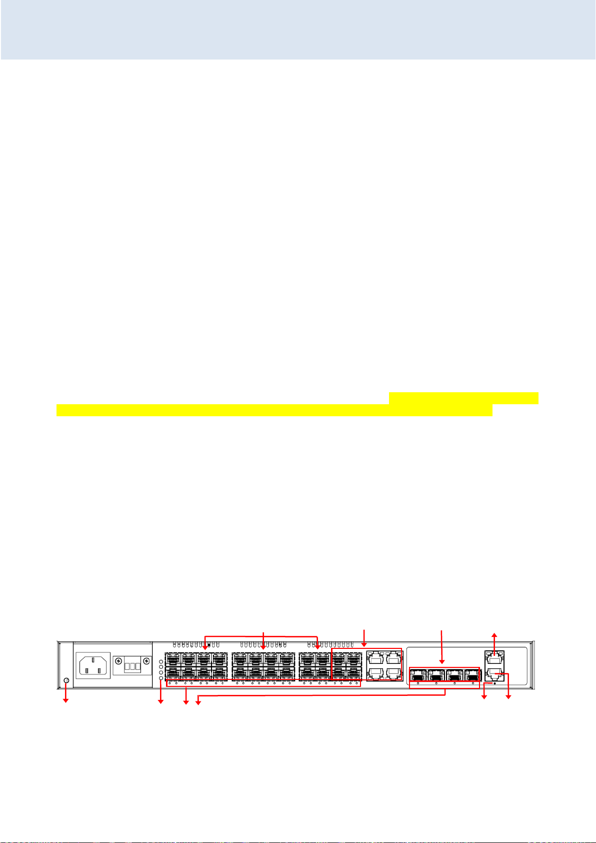
CHAPTER 1
INTRODUCTION
Port21~24
Combo
Power Modules (options available:
AC, DC, 2 AC, 2 DC, AC+DC)
AC
DC
Port1~20
100/1000M SFP
Console Port
Port 25~28
1/10G SFP+
MGMT Port
LED Indicators
Reset to Default
Push Button
Earth Ground
CHAPTER 1. INTRODUCTION
Thank you for purchasing this product from CTC Union. We hope this product is everything you wanted
and more. Our Product Managers and R&D team have placed a "quality first" motto in our development of
this series of Ethernet switches with the desire of providing a highly stable and reliable product that will
give years of trouble-free operation.
In this chapter we will introduce hardware features of MSW-4424C & MSW-4424CS. In chapter 2,
power installation and bracket installation methods will also be provided. MSW-4424C(S) also offer a wide
range of software features that can be managed using serial console and CLI (command line interface),
Telnet, SSH, HTTP (Web GUI) or SNMP (Simple Network Management Protocol). Chapter 4 will detail all of
the configuration settings by using an easy to point and click Web interface which can be accessed from any
available web browser.
1.1 Product Description
MSW-4424C(S) Series are layer 2+ managed Gigabit Ethernet switches that provide stable and reliable
Ethernet transmission for Carrier Ethernet access switch solution. MSW-4424C(S) are designed in standard
1U 19-inch size and can be mountable in standard 19-inch rack. To offer the best flexibility and scalability
for network deployment, MSW-4424C(S) are equipped with 20 SFP-based 100/1000Mbps dual speed
optical ports, 4 Combo (10/100/1000Mbps RJ-45 or 100/1000Mbps SFP) ports and 4 1/10Gbps dual speed
SFP+ uplink ports
MSW-4424C(S) series optionally incorporates redundant power modules. The supply derives its power
from either an AC power source and/or DC power source. When two modules are installed, they provide
for power redundancy. Fans are located on the rear panel of the device. The immediate fan condition can
be observed via FAN LED on the front panel (See page 13) or via Web management (See page 18).
1.2 Panels
The front of the MSW-4424C(S) contains two power slots. Built-in power module or modules from
factory are varied based on the user’s order. You can have one AC power, one DC power, one AC and one
DC power, two AC power supplies or two DC power supplies. Next to power supplies, 20 SFP-based slots, 4
Combo ports, 4 SFP+ uplink ports, one MGMT (management) port and one console port are provided.
MSW-4424CS also provide additional two ports (1PPS/TOD) for time synchronization function. SFP-based
slots are numbered 1 through 28, from left to right as viewed from the front. The device can be configured
via the MGMT or console port. Right next to the power module on the left is the protective earth grounding
terminal. It is highly recommended that a stable ground be attached to this device so that any surges on
power via LAN ports can be properly and safely shunted to ground.
Figure 1. Front Panel for MSW-4424C
18
Page 19
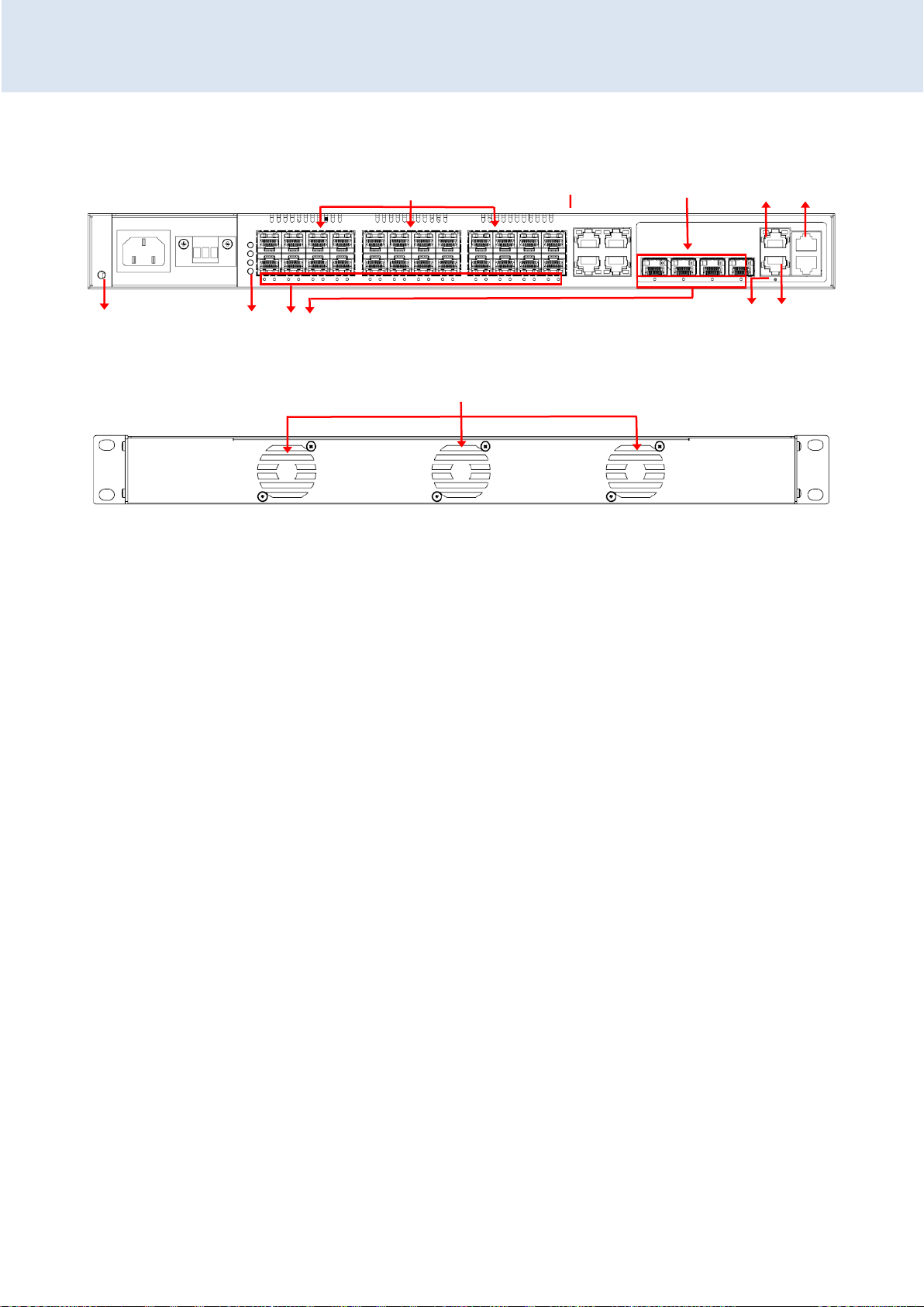
CHAPTER 1
INTRODUCTION
Fan Module
Port21~24
Combo
Power Modules (options available:
AC, DC, 2 AC, 2 DC, AC+DC)
AC
DC
Port1~20
100/1000M SFP
Console
Port
Port 25~28
1/10G SFP+
MGMT
Port
LED Indicators
Default Push
Button
Earth Ground
1PPS/TOD
for SyncE
Figure 2. Front Panel for MSW-4424CS
Figure 3. Rear Panel for MSW-4424C &MSW-4424CS
19
Page 20
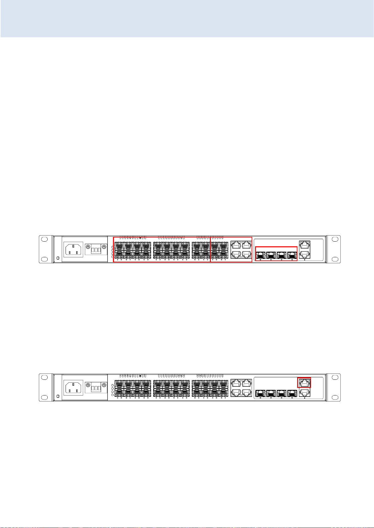
CHAPTER 2
INSTALLATION
CHAPTER 2. INSTALLATION
The MSW-4424C(S) are designed to be placed on the flat desktop or to be mounted in a standardized 19-inch
rack for rack-mount placement. The switch you purchase should come with rack-mounting brackets from the factory
and these brackets are used for rack-mounting installation.
Besides, MSW-4424C(S) are equipped with built-in power and fan modules. Types of power modules available are
AC, DC, AC+DC, two AC and two DC power modules. Fans which are not removable are located on the rear panel of
the device. If you need to repair fan modules, please contact your sales representatives.
In this section, we will provide necessary information about fiber connections, console connection, power
connection and wall-mounting installation. Definitions of LED indicators are also provided at the end of this section.
2.1 Fiber Connections
The MSW-4424C(S) Series utilize SFP modules for fiber transmissions. Each of the fiber ports has an associated
status LED to indicate the presence or absence of fiber link and will also flash when there is Ethernet activity on the
port. For port 1 to port 20, each of SFP cages may insert any standard SFP module and be configured for 100M or
1000M operation. For port 21 to port 24, they are dual media combo ports meaning that you can either use
10/100/1000M RJ-45 or 100/1000M SFP for service connection. For port 25 to port 28, each of SFP cages may insert
any SFP+ module that supports 1/10G Ethernet connectivity. Having SFP+ option for uplink connectivity offers
customers a wide variety of applications for data center, enterprise wiring closet and service provider transport.
Figure 3. Fiber Connections
2.2 MGMT Port Connection
The MSW-4424C(S) have a MGMT (Management) port for in-band management via TCP/IP connectivity. The
MGMT port allows you to access Command Line Interface (CLI) using Telnet or Web management over TCP/IP using
standard web browsers.
When you use the switch for the first time or restore the switch to the factory defaults, you can use RJ-45 cable
to directly connect MGMT port to your management PC. Then, run a Telnet facility or web browser to communicate
with the device over a TCP/IP network using the default IP address 10.1.1.1. For Telnet connection, up to four active
Telnet sessions can access the Switch concurrently. After you successfully login to the switch, you can change the IP
address to the desired one (See Chapter 3 & 4 for setting up new IP address).
Figure 4. MGMT Port Connection
2.3 Console Port Connection
The MSW-4424C(S) have an asynchronous terminal console port for local management via a serial terminal. The
terminal provides management via a CLI (Command Line Interface) which will be familiar to many networking
engineers. For most users, the CLI can be used to initially configure TCP/IP access so that further configuration can be
completed via the GUI (Graphical User Interface) and any web browser.
20
Page 21
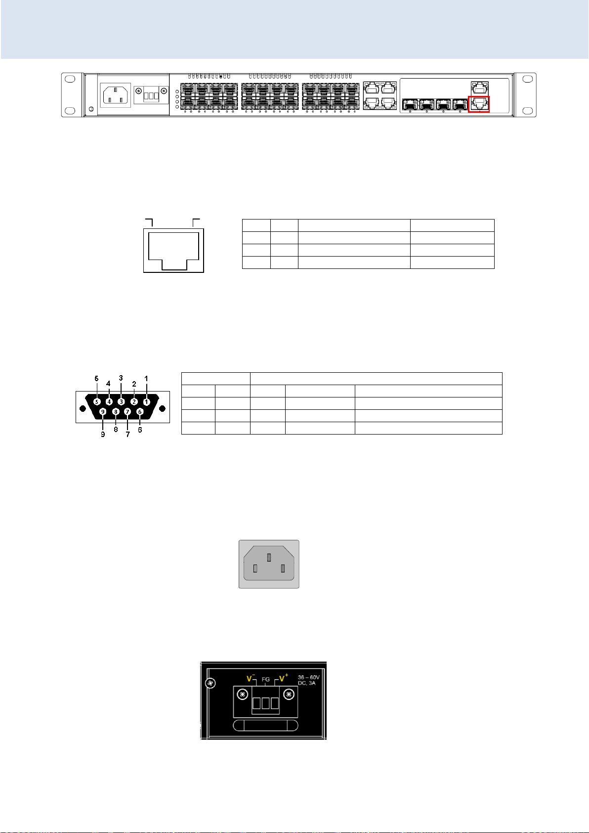
CHAPTER 2
INSTALLATION
Pin
Ref.
Definition
Direction
3
RxD
Receive Data
Out towards DTE
6
TxD
Transmit Data
In from DTE
4
SG
Signal Ground
N/A
Pins
DB9
RJ-45
Ref.
Definition
Direction
2 3 RxD
Receive Data
Out MSW-4424C(S) towards DTE
3 6 TxD
Transmit Data
In MSW-4424C from DTE
5 4 SG
Signal Ground
na
8
1
CONSOLE
to PC COM Port
Left: Live line
Right: Neutral line
Middle: Ground
Left: -V
Right: +V
Middle: Frame Ground
Figure 5. Console Port Connection
2.3.1 RJ-45 Pin Assignment
This RJ-45 connector provides an RS-232 DCE (data communication equipment) asynchronous serial connection
for local management.
2.3.2 Accessory Cable
This DB9F to RJ-45 cable provides a connection for the RS-232. This cable is used between the MSW-4424C(S) and
the serial port of terminal.
2.4 Electrical Installation
AC power module is supplied to the MSW-4424C through a standard IEC C14 3-prong receptacle, located on the
front of the module. Any national power cord with IEC C13 line plug may be used to connect AC power to the power
module.
Figure 6. IEC (AC) Power Connector Pin Assignment
MSW-4424C(S) switches also provide DC module for power connection. The user must connect the device only to
DC input source that has an input supply voltage from -36 to -60 VDC. If the power you use is not in this range, the
device might not operate properly and there is great possibility that the device might be damaged.
Figure 7. Terminal Block (DC) Power Connector Pin Assignment
21
Page 22
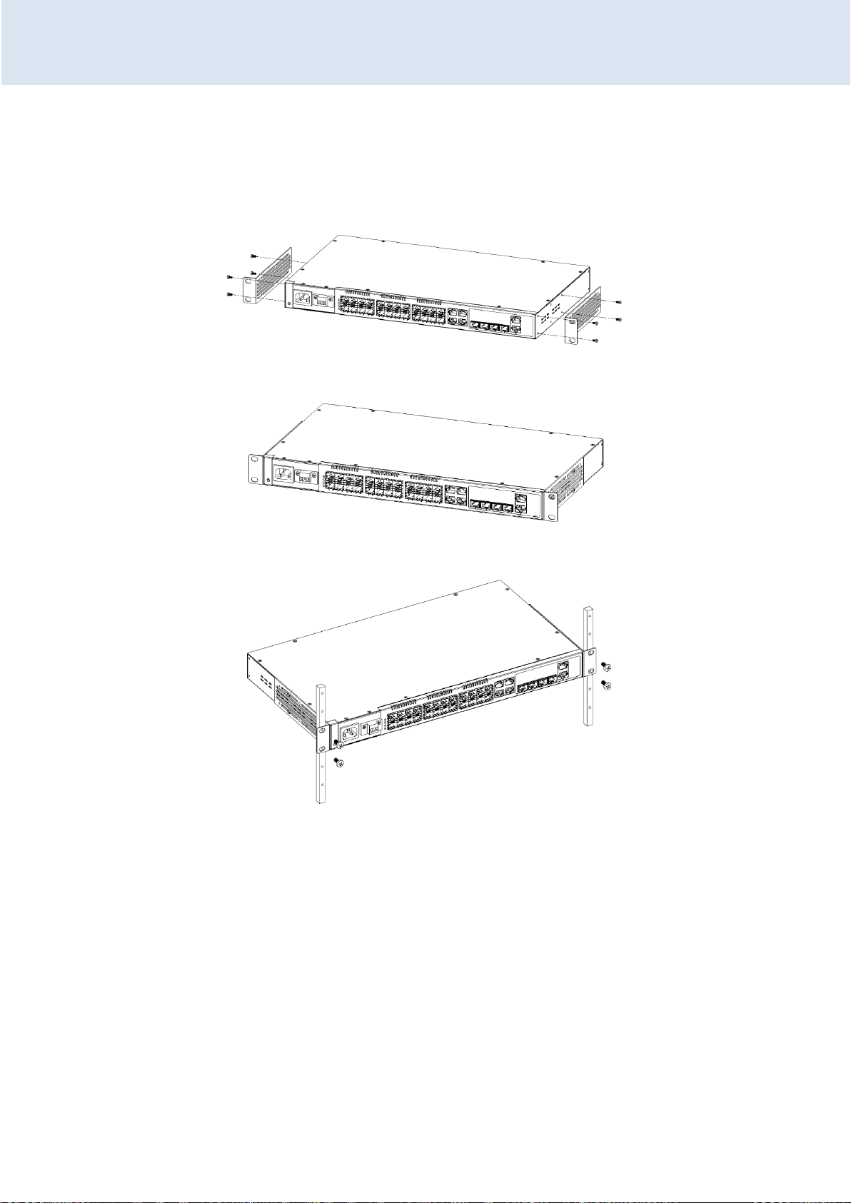
CHAPTER 2
INSTALLATION
2.5 Rack Mounting
When installing the rack mount brackets, be sure to correctly align the orientation pin. Use the screws provided
in the rack-mounting kit to securely fasten the brackets.
Figure 8. Attaching Rack-Mounting Brackets
Figure 9. The Switch with Rack-Mounting Brackets
Figure 10. Mounting in Rack
22
Page 23

CHAPTER 2
INSTALLATION
LED
Color
Status
Meaning
ACT
Green
On
The switch is active.
Red
On
Alert
Off
The switch does not receive power.
PWR 1
Green
On
Power 1 module is working.
Off
Power 1 module is off.
PWR 2
Green
On
Power 2 module is working.
Off
Power 2 module is off.
FAN
Green
On
Fan is working normally.
Red
On
Fan is working abnormally. This indicates Fan alarm status.
Off
Fan module is off.
1~20
Green
On
Port link is up and works in 100Mbps.
Blinking
Traffic is present.
Off
Port link is down or has no link.
Yellow
On
Port link is up and works in 1000Mbps.
Blinking
Traffic is present.
Off
Port link is down or has no link.
21~24
SFP
Green
On
Port link is up and works in 100Mbps.
Blinking
Traffic is present.
Off
Port link is down or has no link.
Yellow
On
Port link is up and works in 1000Mbps.
Blinking
Traffic is present.
Off
Port link is down or has no link.
21~24
RJ-45
Green
On
Port link is up and works in 100Mbps.
Yellow
On
Port link is up and works in 1000Mbps.
Green
Blinking
Traffic is present.
Green/Yellow
Off
Port link is down or has no link.
25~28
Orange
On
Port link is up and works in 1Gbps.
Blinking
Traffic is present.
Off
Port link is down or has no link.
Blue
On
Port link is up and works in 10Gbps.
Blinking
Traffic is present.
Off
Port link is down or has no link.
Reset to default button
Press and hold the button for 7 seconds and then release to reset
the device to factory default settings.
2.6 LED Indicators & Reset to Default Button
23
Page 24

CHAPTER 3
INTRODUCTION TO CLI
Speed:
115,200
Data:
8 bits
Parity:
None
Stop bits:
1
Flow control:
None
Platform: VCore-III (MIPS32 24KEc) JAGUAR
RAM: 0x80000000-0x88000000 [0x80021798-0x87fe0000 available]
FLASH: 0x40000000-0x40ffffff, 256 x 0x10000 blocks
== Executing boot script in 2.000 seconds - enter ^C to abort
RedBoot> fi lo -a -f managed
Image loaded from 0x80040000-0x80b7c61c
RedBoot> go
Press ENTER to get started
Username: admin
Password:
#
CHAPTER 3. INTRODUCTION TO CLI
3.1 Introduction
The MSW-4424C(S) Series of L2+ Carrier Gigabit Ethernet switches provide a number of
configuration/management methods. The first and very basic is serial console access. This method is also called outof-band management and is only available when a terminal or administrator PC can be physically connected to the
local MSW-4424C(S) Series switch at the CONSOLE port using RJ45 to RS-232 console cable. Accessing the switch via
CONSOLE port allows the user to use CLI (Command Line Interface) to manage and configure the device. The out-ofband management is relatively useful when you lose the network connection to the device.
On the other hand, in-band management enables you to manage the device remotely using the device’s IP
address. Using in-band management enables you to use Telnet console (CLI) or web browser (GUI) to access the
device. If you plan on using in-band management, you need to configure the device’s IP address first before it can be
accessed via a LAN port.
The out-of-band management via console access, using a command line (CLI), is familiar to most network
engineers. For engineers that are not comfortable using CLI, this device can also be managed using any standard Web
Browser in a more user friendly 'point-and-click' method. Therefore, in most configuration scenarios, the console will
only be used to initially configure the IP address, so that the device may be accessed via the other methods which
require working TCP/IP.
After the device has been properly configured for the application and placed into service, a third method of
configuration/management can be employed using Simple Network Management Protocol (SNMP). The operator will
use SNMP management software to manage and monitor the MSW-4424C(S) Series switches on a network. This
requires some configuration of the device to allow SNMP management. In addition, the network management
platform will need to import and compile the proprietary MIB (management information base) file so that the
manager knows "how" to manage the MSW-4424C(S).
3.2 CONSOLE Operation
Use the provided accessory cable to connect the "CONSOLE" port (RJ-45) to the PC terminal communications port
(DB9). Run any terminal emulation program (HyperTerminal, PuTTY, TeraTerm Pro, etc.) and configure the
communication parameters as follows:
From a cold start, the following screen will be displayed. At the "Username" prompt, enter 'admin' with no
password.
24
Page 25

CHAPTER 3
INTRODUCTION TO CLI
Mode
Prompt
Enter Method
Exit Method
User mode
>
enable
disable
EXEC mode
#
Enter authorized
username and
password
Exit, logout
Global Config
Mode
(config)#
Enter “configure
terminal” after “#”
End, exit, do logout
Config Interface
Mode
(config-if)#
Specify interface,
interface type and
number after
(config)#
End, exit, do logout
Keyboard
Action
?
Issue “?” to get a list of commands available in the current
mode.
Up arrow key
To view the previous entered commands.
Down arrow key
To view the previous entered commands.
Tab key
To complete an unfinished command.
Symbol
Function
Example
Explanation
< > (Angle
bracket)
Enter a value, alphanumeric
strings or keywords.
<address> <netmask>
Enter IP address and subnet
mask.
[ ]
(Square
bracket)
This is an optional parameter.
[ fallback <fallback_address>
<fallback_netmask> [ timeout
<fallback_timeout> ] ]
Fallback parameter is an
optional item.
{ } (Curly
bracket)
A curly bracket has the
following two functions:
1. If there are more than two
options available, a curly
bracket can be used to
{ { <address> <netmask> } |
{ dhcp [ fallback
<fallback_address>
<fallback_netmask> [ timeout
<fallback_timeout> ] ] } }
At least specify one option
to complete the command.
3.3 CLI Modes
The Command Line Interface (CLI) is mainly divided into four basic modes; these are User mode, EXEC mode,
Config mode and Config Interface mode. After entering the username and password, you start from the EXEC mode
(prompted with “#”). The commands available in User mode and EXEC mode are limited. For more advanced
configurations, you must enter Config mode or Config Interface mode. In each mode, a question mark (?) at the
system prompt can be issued to obtain a list of commands available for each command mode. The following table
provides a brief overview of modes available in this device.
3.4 Quick Keys
There are several useful quick keys you can use when editing command lines.
3.5 Command Syntax
Commands introduced in this user manual are written using the coherent symbols and easy-to-understand syntax
and style. Although users can issue Help command to complete a desired command in CLI, it is useful to understand
frequently-used symbols and syntax conventions. The following table lists the syntax conventions used in this user
manual together with an example.
Example: (config-if-vlan)# ip address { { <address> <netmask> } | { dhcp [ fallback <fallback_address>
<fallback_netmask> [ timeout <fallback_timeout> ] ] } }
25
Page 26

CHAPTER 3
INTRODUCTION TO CLI
separate them.
2. The uter curly bracket
means that this is a must
parameter. At leaset one
value should be specified.
| (Vertical
bar)
Use a vertical bar to separate
options.
{ { <address> <netmask> } |
{ dhcp [ fallback
<fallback_address>
<fallback_netmask> [ timeout
<fallback_timeout> ] ] } }
Enter IP address or use
DHCP to assign IP address
automatically.
# config terminal
(config)# interface vlan 1
(config-if-vlan)# ip address 192.168.0.101 255.255.255.0
(config-if-vlan)# exit
(config)# exit
# show ip interface brief
Vlan Address Method Status
---- -------------------- -------- ----- 1 192.168.0.101/24 Manual DOWN
# config terminal
(config)# interface GigabitEthernet 1/3
(config-if)#
# config terminal
(config)# interface GigabitEthernet 1/1-3
(config-if)#
# config terminal
(config)# interface GigabitEthernet 1/1-3,5
(config-if)#
3.6 Basic Configurations
This section introduces users how to change the default IP address to the desired one and save the current
running configurations to startup configurations. For detailed introductions to commands, please see section 3.7, 3.8,
3.9.
3.6.1 Configuring IPv4 Address
IP address: 192.168.0. 101
Subnet mask: 255.255.255.0
3.6.2 Enter Config Interface Mode
Enter Port 3’s Config Interface mode.
Note: 1/3 means Ethernet Interface 1, Port 3.
Enter Port 1~3’s Config Interface mode.
Note: 1/1-3 means Ethernet Interface 1, Port 1 to Port 3.
Enter Port 1~3 & Port 5’s Config Interface mode.
Note: 1/1-3,5 means Ethernet Interface 1, Port 1 to Port 3 and Port 5.
26
Page 27
CHAPTER 3
INTRODUCTION TO CLI
# copy running-config startup-config
Building configuration...
% Saving 1469 bytes to flash:startup-config
#
# reload cold
% Cold reload in progress, please stand by.
#
Copyright (C) 2000, 2001, 2002, 2003, 2004, 2005, 2006, 2007, 2008, 2009
Free Software Foundation, Inc.
RedBoot is free software, covered by the eCos license, derived from the
GNU General Public License. You are welcome to change it and/or distribute
copies of it under certain conditions. Under the license terms, RedBoot's
source code and full license terms must have been made available to you.
Redboot comes with ABSOLUTELY NO WARRANTY.
RedBoot> fi lo -d managed
Image loaded from 0x80040000-0x80ae54cc
RedBoot> go
Press ENTER to get started
# reload defaults
% Reloading defaults. Please stand by.
# reload defaults keep-ip
% Reloading defaults, attempting to keep VLAN 1 IP address. Please stand by.
# show version
MEMORY
MAC Address
Previous Restart
System Contact
System Name
System Location
System Time
System Uptime
Active Image
: Total=77679 KBytes, Free=51457 KBytes, Max=51417 KBytes
: 00-02-ab-00-00-01
: Cold
:
:
:
: 2015-01-01T00:28:35+00:00
: 00:28:39
3.6.3 Save Configurations
3.6.4 Restart the Device
3.6.5 Load Factory Defaults
Load factory default settings
Load factory defaults but keep IP settings
3.6.6 Show System and Software Information
27
Page 28
CHAPTER 3
INTRODUCTION TO CLI
-----------------Image
Version
Date
Alternative Image
-----------------Image
Version
Date
-----------------SID : 1
------------------
Software Version
Build Date
managed
:
: 2015-01-01T00:03:06+00:00
: managed.bk
: 2015-08-03T16:21:44+08:00
: V1.038
: 2015-08-03T16:33:15+08:00
# show running-config
Building configuration...
username admin privilege 15 password none
!
vlan 1
!
!
!
no smtp server
spanning-tree mst name 00-02-ab-00-00-01 revision 0
!
interface GigabitEthernet 1/1
no spanning-tree
!
interface GigabitEthernet 1/2
no spanning-tree
!
interface GigabitEthernet 1/3
no spanning-tree
!
interface GigabitEthernet 1/4
no spanning-tree
!
-- more --, next page: Space, continue: g, quit: ^C
# show history
config t
exit
config t
ip arp ex
exit
> show history
config t
interface GigabitEthernet 1/3
exit
3.6.7 Show Running Configurations
3.6.8 Show History Commands
28
Page 29
CHAPTER 3
INTRODUCTION TO CLI
interface GigabitEthernet 1/1-5
exit
interface GigabitEthernet 1/1-3,5,7
flowcontrol on
exit
show interface * status
disable
show clock detail
show dot1x
show history
# help
Help may be requested at any point in a command by entering
a question mark '?'. If nothing matches, the help list will
be empty and you must backup until entering a '?' shows the
available options.
Two styles of help are provided:
1. Full help is available when you are ready to enter a
command argument (e.g. 'show ?') and describes each possible
argument.
2. Partial help is provided when an abbreviated argument is entered
and you want to know what arguments match the input
(e.g. 'show pr?'.)
(config)# exit
# logout
Press ENTER to get started
# disable
> logout
Press ENTER to get started
Username: admin
Password:
#
# disable
>
3.6.9 Help
Help command can be issued in User, Exec, and Global Config mode to get a hint message describing how to use
“show” command to get help from CLI.
3.6.10 Logout
To close an active terminal session, issue the “logout” command in User or EXEC mode.
3.7 Commands in User Mode
When you successfully login in Command Line Interface, you are in EXEC Mode (prompted with “#”). To enter
User mode, issue “disable” command after # prompt. Then you will be directed to User mode with “>” prompt.
29
Page 30

CHAPTER 3
INTRODUCTION TO CLI
In User mode, only limited commands are available. These commands are used for clearing statistics, entering
Exec mode and pinging the specified destination. To configure a function, you should enter Config mode or Config
Interface mode.
3.7.1 > clear ip arp
Syntax: > clear ip arp
Explanation: Clear ARP cache.
3.7.2 > clear lldp statistics
Syntax: > clear lldp statistics
Explanation: Clear LLDP statistics.
3.7.3 > clear statistics
Syntax: > clear statistics {[ interface ] ( <port_type> [ <v_port_type_list> ] )}
<port_type>: Specify the interface type.
[ <v_port_type_list>: Specify the ports that you want to clear.
Explanation: Clear statistics of the specified interfaces.
3.7.4 > enable
Syntax: > enable [ <new_priv> ]
[ <new_priv: 0-15> ]: Choose a privilege level.
Explanation: Enter the EXEC mode.
3.7.5 > exit
Syntax: > exit
Explanation: Return to the previous mode. Issuing this command in User mode will logout the Command Line
Interface.
3.7.6 > help
Syntax: > help
30
Page 31

CHAPTER 3
INTRODUCTION TO CLI
Explanation: Provide help messages.
3.7.7 > logout
Syntax: > logout
Explanation: Logout the Command Line Interface.
3.7.8 > ping ip
Syntax: > ping ip <v_ip_addr> [ repeat <count> ] [ size <size> ] [ interval <seconds> ]
<v_ip_addr>: Specify IPv4 address that you want to ping.
[ repeat <count> ]: The number of packets that are sent to the destination IP or host.
[ size <size> ]: The size of the packet.
[ interval <seconds> ]: Timeout interval. The ping test is successful only when it receives echo reply from the
destination IP or host within the time specified here.
Explanation: To carry out ping tests on the specified destination IPv4 address or host.
3.7.9 > ping ipv6
Syntax: > ping ipv6 <v_ipv6_addr> [ repeat <count> ] [ size <size> ] [ interval <seconds> ] [ interface vlan <v_vlan_id> ]
<v_ipv6_addr>: Specify IPv6 address that you want to ping.
[ repeat <count> ]: The number of packets that are sent to the destination IP or host.
[ size <size> ]: The size of the ping packet.
[ interval <seconds> ]: Timeout interval. The ping test is successful only when it receives echo reply from the
destination IP or host within the time specified here.
[ interface vlan <v_vlan_id> ]:
Explanation: To carry out ping tests on the specified destination IPv6 address or host.
3.7.10 show commands
In User mode, “show” commands can be issued to display current status or settings of a certain command. They
will be introduced in Section 3.9 “Commands in Config Mode”.
31
Page 32

CHAPTER 3
INTRODUCTION TO CLI
3.8 Commands in EXEC Mode
3.8.1 # clear access management statistics
Syntax: # clear access management statistics
Explanation: Clear access (HTTP, HTTPs, SNMP, Telnet, SSH) management statistics.
3.8.2 # clear access-list ace statistics
Syntax: # clear access-list ace statistics
Explanation: Clear access list entry statistics.
3.8.3 # clear dot1x statistics
Syntax: # clear dot1x statistics [ interface ( <port_type> [ <v_port_type_list> ] ) ]
Parameter:
[ interface ( <port_type> [ <v_port_type_list> ] ) ]: Specify the interface that you want to clear.
Explanation: Clear (the specified interfaces’) dot1x statistics.
3.8.4 # clear eps
Syntax: # clear eps <inst> wtr
Parameter:
<inst>: Specify the EPS instance number.
Explanation: Clear the specified EPS instance.
3.8.5 # clear erps
Syntax: # clear erps [ <groups> ] statistics
Parameter:
[ <groups> ]: Specify the ERPS group that you want to clear.
Explanation: Clear (the specified group’s) ERPS statistics.
3.8.6 # clear evc statistics
Syntax: # clear evc statistics { [ <evc_id> | all ] } [ ece [ <ece_id> ] ] [ interface ( <port_type> [ <port_list> ] ) ]
32
Page 33

CHAPTER 3
INTRODUCTION TO CLI
Parameter:
{ [ <evc_id> | all ] }: Clear all or the specified EVC ID's EVC statistics.
[ ece [ <ece_id> ] ]: Clear the specified ECE ID's EVC statistics.
[ interface ( <port_type> [ <port_list> ] ) ]: Clear the specified interface's EVC statistics.
Explanation: Clear Ethernet Virtual Connections statistics.
3.8.7 # clear ip arp
Syntax: # clear ip arp
Explanation: Clear ARP cache.
3.8.8 # clear ip dhcp detailed statistics
Syntax: # clear ip dhcp detailed statistics { server | client | snooping | relay | helper | all } [ interface ( <port_type>
[ <in_port_list> ] ) ]
Explanation: ClearIP DHCP statistics.
Parameter:
{ server | client | snooping | relay | helper | all }: Specify the type of information that you want to clear.
[ interface ( <port_type> [ <in_port_list> ] ) ]: Specify the interface type and port number.
3.8.9 # clear ip dhcp relay statistics
Syntax: # clear ip dhcp relay statistics
Explanation: Clear IP DHCP Relay statistics.
3.8.10 # clear ip dhcp server binding <ip>
Syntax: # clear ip dhcp server binding <ip>
Explanation: Clear IP DHCP server IP binding information.
3.8.11 # clear ip dhcp server binding { automatic | manual | expired }
Syntax: # clear ip dhcp server binding { automatic | manual | expired }
Explanation: Clear IP DHCP server binding information.
33
Page 34

CHAPTER 3
INTRODUCTION TO CLI
3.8.12 # clear ip dhcp server statistics
Syntax: # clear ip dhcp server statistics
Explanation: Clear IP DHCP server binding statisctics.
3.8.13 # clear ip dhcp snooping statistics
Syntax: # clear ip dhcp snooping statistics [ interface ( <port_type> [ <in_port_list> ] ) ]
Explanation: Clear IP DHCP Snooping statistics.
3.8.14 # clear ip igmp snooping
Syntax: # clear ip igmp snooping [ vlan <v_vlan_list> ] statistics
Explanation: Clear IP IGMP Snooping statistics.
3.8.15 # clear ip statistics
Syntax: # clear ip statistics [ system ] [ interface vlan <v_vlan_list> ] [ icmp ] [ icmp-msg <type> ]
Explanation: Clear IPv4 statistics for system, interface and ICMP.
3.8.16 # clear ipv6 mld snooping
Syntax: # clear ipv6 mld snooping [ vlan <v_vlan_list> ] statistics
Explanation: Clear statistics for IPv6 MLD Snooping.
3.8.17 # clear ipv6 neighbors
Syntax: # clear ipv6 neighbors
Explanation: Clear the table for IPv6 neighbors.
3.8.18 # clear ipv6 statistics
Syntax: # clear ipv6 statistics [ system ] [ interface vlan <v_vlan_list> ] [ icmp ] [ icmp-msg <type> ]
Explanation: Clear IPv6 statistics for system, interface and ICMP.
34
Page 35

CHAPTER 3
INTRODUCTION TO CLI
3.8.19 # clear lacp statistics
Syntax: # clear lacp statistics
Explanation: Clear LACP statistics.
3.8.20 # clear lldp statistics
Syntax: # clear lldp statistics
Explanation: Clear LLDP statistics.
3.8.21 # clear logging
Syntax: # clear logging [ info ] [ warning ] [ error ] [ switch <switch_list> ]
Explanation: Clear specific syslog events.
3.8.22 # clear mac address-table
Syntax: # clear mac address-table
Explanation: Clear MAC address table.
3.8.23 # clear mep
Syntax: # clear mep <inst> { lm | dm | tst }
Explanation: Clear a specific instance MEP information.
3.8.24 # clear mvr
Syntax: # clear mvr [ vlan <v_vlan_list> | name <mvr_name> ] statistics
Explanation: Clear MVR statistics.
3.8.25 # clear spanning-tree
Syntax: # clear spanning-tree { { statistics [ interface ( <port_type> [ <v_port_type_list> ] ) ] } | { detected-protocols
[ interface ( <port_type> [ <v_port_type_list_1> ] ) ] } }
Explanation: Clear specific interfaces’ Spanning Tree statistics.
35
Page 36
CHAPTER 3
INTRODUCTION TO CLI
# copy running-config Flash:201
Building configuration...
% Saving 1487 bytes to flash:201
# dir
Directory of flash:
r- 1970-01-01 00:00:00 284 default-config
rw 2015-01-01 01:56:32 1487 startup-config
rw 2015-01-01 01:56:49 1487 201
3 files, 3258 bytes total.
# copy startup-config running-config
Building configuration...
% Saving 1596 bytes to flash:startup-config
#
# copy running-config startup-config
Building configuration...
% Saving 1596 bytes to flash:startup-config
#
# config t
(config)#
3.8.26 # clear statistics
Syntax: # clear statistics [ interface ] ( <port_type> [ <v_port_type_list> ] )
Explanation: Clear Fast Ethernet and/or Gigabit Ethernet interfaces’ statistics.
3.8.27 # config terminal
Syntax: # config terminal
Explanation: Enter the Global Config mode.
Example:
3.8.28 # copy
Syntax: # copy { startup-config | running-config | <source_path> } { startup-config | running-config |
<destination_path> } [ syntax-check ]
{ startup-config | running-config | <source_path> }: Specify the file type that you want to copy from. This can be
“startup-config”, “running-config” or a specific source file in flash or TFTP server.
{ startup-config | running-config | <destination_path> }: Specify the file type that you want to copy to. This can
be “startup-config”, “running-config” or a specific destination file in flash or TFTP server.
Explanation: Save running configurations to startup configurations.
Example: Save running configurations to startup configurations.
Explanation: Save startup configurations to running configurations.
Example: Save running configurations to startup configurations.
Explanation: Save running configurations to Flash 201
36
Page 37

CHAPTER 3
INTRODUCTION TO CLI
# dir
Directory of flash:
r- 1970-01-01 00:00:00 284 default-config
rw 2015-01-01 01:56:32 1487 startup-config
rw 2015-01-01 01:56:49 1487 201
3 files, 3258 bytes total.
# delete flash:201
# dir
Directory of flash:
r- 1970-01-01 00:00:00 284 default-config
rw 2015-01-01 01:56:32 1487 startup-config
2 files, 1771 bytes total.
# dir
Directory of flash:
r- 1970-01-01 00:00:00 284 default-config
rw 2015-01-01 01:56:32 1487 startup-config
rw 2015-01-01 01:56:49 1487 201
3 files, 3258 bytes total.
3.8.29 # delete
Syntax: # delete <path>
Explanation: Delete a file saved in Flash.
Parameters:
<Path : word>: Name of the file in Flash to be deleted.
Example: Delete a file named 201 in Flash.
3.8.30 # dir
Explanation: Display files in flash.
Example:
37
Page 38
CHAPTER 3
INTRODUCTION TO CLI
# disable
>
>
> enable
#
#
# enable 0
>
3.8.31 # disable & # enable
Explanation: Return to user mode or enter exec mode.
3.8.32 # dot1x
Syntax: # dot1x initialize [ interface ( <port_type> [ <plist> ] )
[ interface ( <port_type> [ <plist> ] ) ]: Specify the type of interface that you intend to use. “*” means all
interfaces.
<plist>: Specify the ports that apply to this command.
Explanation: To initialize dot1x function in an interface immediately.
3.8.33 # erps
Syntax: # erps <group> command {clear | force | manual} {port0 | port1}
Explanation: Configure ERPS instance.
Parameters:
<group: 1-64>: Specify a group number between 1~64.
{clear | force | manual}: Specify an action.
{port0 | port1}: Specify port0 (east) or port1 (west) that applies to this command.
3.8.34 # firmware swap
Syntax: # firmware swap
Explanation: Use the other standby firmware image file uploaded to flash.
38
Page 39

CHAPTER 3
INTRODUCTION TO CLI
3.8.35 # firmware upgrade
Syntax: # firmware upgrade <TFTPServer_path_file : word>
<TFTPServer_path_file : word>: Specify the TFTP server IP address and firmware filename.
Explanation: Upgrade the firmware image.
3.8.36 # ip dhcp retry interface vlan
Syntax: # ip dhcp retry interface vlan <vlan_id>
<vlan_id>: Specify the valid VLAN ID for DHCP query.
Explanation: Restart the DHCP query process.
3.8.37 # more
Syntax: # more <path>
<path>: Specify the filename.
Explanation: Display file in Flash or in TFTP server.
3.8.38 # ping ip
Syntax: # ping ip <v_ip_addr> [ repeat <count> ] [ size <size> ] [ interval <seconds> ]
Explanation: Ping the specified IP.
Parameters:
<addr>: Specify the IPv4 address or IPv6 address for ping test.
3.8.39 # ping ipv6
Syntax: #ping ipv6 <v_ipv6_addr> [ repeat <count> ] [ size <size> ] [ interval <seconds> ] [ interface vlan <v_vlan_id> ]
< v_ipv6_addr >: Specify the IPv4 address or IPv6 address for ping test.
Explanation: Ping the specified IPv6 address.
Parameters:
[ repeat <count> ]: The number of echo packets will be sent.
39
Page 40

CHAPTER 3
INTRODUCTION TO CLI
[ size <size> ]: The size or length of echo packets.
[ interval <seconds> ]: The time interval between each ping request.
[ interface vlan <v_vlan_id> ]: Specify the VLAN ID.
3.8.40 # reload cold
Syntax: # reload cold
Explanation: Perform a cold reload on the system.
3.8.41 # reload defaults
Syntax: # reload defaults [keep-ip]
Explanation: Restore the device to factory default settings.
Parameters:
[keep-ip]: Keep VLAN 1 IP setting.
3.8.42 # send
Syntax: # send { * | <session_list> | console 0 | vty <vty_list> } <message>
Explanation: Send messages to other tty lines.
Parameters:
{ * | <session_list> | console 0 | vty <vty_list> }: Choose one of the options.
* : Specify “*” to denote all tty users.
<session_list>: Specify a session number between 0 and 16.
console 0: This means primary terminal line.
<vty_list>: Send a message to a virtual terminal.
<message>: Enter a message in 128 characters that you want to send.
3.8.43 # terminal editing
Syntax: # terminal editing
Explanation: Enable command line editing.
Show: > show terminal
# show terminal
40
Page 41

CHAPTER 3
INTRODUCTION TO CLI
Negation: # no terminal editing
3.8.44 # terminal exec-timeout
Syntax: # terminal exec-timeout <0-1440> [<0-3600>]
Parameters:
<0-1440>: Specify the timeout value in minutes.
[<0-3600>]: Specify the timeout value in seconds.
Explanation: Set up terminal timeout value.
Show: > show terminal
# show terminal
Negation: # no terminal exec-timeout
3.8.45 # terminal history size
Syntax: # terminal history size <0-32>
Parameters:
<0-32>: Specify the current history size. “0” means to disable.
Explanation: Set up terminal history size.
Show: > show terminal
# show terminal
Negation: # no terminal history size
3.8.46 # terminal length
Syntax: # terminal length <0 or 3-512>
Parameters:
<0 or 3-512>: Specify the lines displayed on the screen. “0” means no pausing.
Explanation: Set up terminal length.
Show: > show terminal
# show terminal
Negation: # no terminal length
41
Page 42

CHAPTER 3
INTRODUCTION TO CLI
3.8.47 # terminal width
Syntax: # terminal width <0 or 40-512>
Parameters:
<0 or 40-512>: Specify the width displayed on the screen. “0” means unlimited width.
Explanation: Set up terminal display width.
Show: > show terminal
# show terminal
Negation: # no terminal width
3.8.48 # no port-security shutdown
Syntax: # no port-security shutdown [interface (<port_type>[<v_port_type_list>])]
Explanation: Reopen ports that are shutdown or disabled by Port Security function.
Parameters:
[interface (<port_type>[<v_port_type_list>])]: Specify the port type and port numbers that you want to reopen.
3.8.49 show commands
In Exec mode, “show” commands can be issued to display current status or settings of a certain command. They
will be introduced in Section 3.9 “Commands in Config Mode”.
3.9 Commands in Config Mode
3.9.1 (config)# aaa authentication login
Syntax: (config)# aaa authentication login { console | telnet | ssh | http } { { local | radius | tacacs } [ { local | radius |
tacacs } [ { local | radius | tacacs } ] ] }
Explanation: Configure the authentication method for the client.
Parameters:
{ console | telnet | ssh | http }: Specify one of the authentication clients.
{ { local | radius | tacacs } [ { local | radius | tacacs } [ { local | radius | tacacs } ] ] }: Specify one of the
authentication methods for the specified client. At least one method needs to be specified. Users can specify
three methods at most.
local: Use the local user database on the switch for authentication.
radius: Use remote RADIUS server(s) for authentication.
42
Page 43

CHAPTER 3
INTRODUCTION TO CLI
NOTE: Methods that involve remote servers will time out if the remote servers are offline. In this case the next method
is tried. Each method is tried and continues until a method either approves or rejects a user. If a remote server is used
for primary authentication it is recommended to configure secondary authentication as 'local'. This will enable the
management client to login via the local user database if none of the configured authentication servers are alive.
# config t
(config)# access management 1 1 192.168.0.1 to 192.168.0.10 all
# config t
(config)# aaa authentication login console radius
tacacs: Use remote TACACS+ server(s) for authentication.
Example: Set the Console client to use remote RADIUS server(s) for authentication.
Negation: (config)# no aaa authentication login { console | telnet | ssh | http }
Show: # show aaa
3.9.2 (config)# access management
Syntax: (config)# access management <access_id> <access_vid> <start_addr> [ to <end_addr> ] { [ web ] [ snmp ]
[ telnet ] | all }
Explanation: Create an access management rule.
Parameters:
<access_id: 1-16>: Specify an ID for this access management entry.
<access_vid>: Indicates the VLAN ID for the access management entry.
<start_addr> [ to <end_addr> ]: Indicate the starting and ending IP address for the access management entry.
{ [ web ] [ snmp ] [ telnet ] | all }: Specify matched hosts can access the switch from which interface.
Example: Allow IP 192.168.0.1 to 192.168.0.10 to access the device via Web, SNMP and Telnet.
Negation: (config)# no access management
(config)# no access management <access_id>
Show: # show access management [ statistics | <access_id_list> ]
Clear: # clear access management statistics
43
Page 44

CHAPTER 3
INTRODUCTION TO CLI
3.9.3 (config)# access-list
3.9.3.1 (config)# access-list ace
Syntax: (config)# access-list ace <AceId : 1-256> [ action {deny | filter | permit}] [ dmac-type {any| broadcast |
multicast | unicast } ] [frame-type {any| arp|etype|ipv4|ipv4-icmp|ipv4-tcp|ipv4-udp|ipv6|ipv6-icmp|ipv6-tcp|ipv6udp} ] [ingress {any | interface <PORT_TYPE> }] [logging] [next { <AceId : 1-256>|last}] [policy <PolicyId : 0-255>] [ratelimiter {<RateLimiterId : 1-16>|disable}] [redirect {disable| interface <PORT_TYPE>}] [shutdown] [tag
{any|tagged|untagged}] [tag-priority {0-1| 0-3| 2-3| 4-5| 4-7| 6-7| <TagPriority : 0-7>|any}] [vid { <Vid : 14095>|any}]
Explanation: Configure an access control list.
Parameters:
<AceId : 1-256>: Specify access control list ID that applies to this rule.
[ action {deny | filter | permit}]: Specify the action that applies to this rule.
[ dmac-type {any| broadcast | multicast | unicast } ]: Specify destination MAC type that applies to this rule.
[frame-type {any| arp|etype|ipv4|ipv4-icmp|ipv4-tcp|ipv4-udp|ipv6|ipv6-icmp|ipv6-tcp|ipv6-udp} ]: Specify
the frame type that applies to this rule.
[ingress {any | interface <PORT_TYPE> }]: Specify the ingress port.
[logging]: Enable logging function.
[mirror]: Enable the function of mirroring frames to destination mirror port.
[next { <AceId : 1-256>|last}]: Insert the current ACE ID before the next ACE ID or put the ACE ID to the last one.
[policy <PolicyId : 0-255>]: Specify the policy ID.
[rate-limiter {<RateLimiterId : 1-16>|disable}]: Specify the rate limit ID or disable this function.
[redirect {disable| interface <PORT_TYPE>}]: Redirect frames to a specific port or disable this function.
[shutdown]: Enable shutdown function.
[tag {any|tagged|untagged}]: Specify whether frames should be tagged or untagged.
[tag-priority {0-1| 0-3| 2-3| 4-5| 4-7| 6-7| <TagPriority : 0-7>|any}]: Specify the priority value.
[vid { <Vid : 1-4095>|any}]: Specify the VLAN ID.
Show: # show access-list [ interface [ ( <port_type> [ <v_port_type_list> ] ) ] ] [ rate-limiter [ <rate_limiter_list> ] ] [ ace
statistics [ <ace_list> ] ]
Negation: (config)# no access-list ace <ace_list>
Clear: # clear access-list ace statistics
44
Page 45

CHAPTER 3
INTRODUCTION TO CLI
3.9.3.2 (config)# access-list ace update
Syntax: (config)# access-list ace update <AceId : 1-256> [ action {deny | filter | permit}] [ dmac-type {any| broadcast |
multicast | unicast } ] [frame-type {any| arp|etype|ipv4|ipv4-icmp|ipv4-tcp|ipv4-udp|ipv6|ipv6-icmp|ipv6-tcp|ipv6udp} ] [ingress {any | interface <PORT_TYPE> }] [logging] [next { <AceId : 1-256>|last}] [policy <PolicyId : 0-255>] [ratelimiter {<RateLimiterId : 1-16>|disable}] [redirect {disable| interface <PORT_TYPE>}] [shutdown] [tag
{any|tagged|untagged}] [tag-priority {0-1| 0-3| 2-3| 4-5| 4-7| 6-7| <TagPriority : 0-7>|any}] [vid { <Vid : 14095>|any}]
Explanation: Update an access control list.
Parameters:
<AceId : 1-256>: Specify access control list ID that applies to this rule.
[ action {deny | filter | permit}]: Specify the action that applies to this rule.
[ dmac-type {any| broadcast | multicast | unicast } ]: Specify destination MAC type that applies to this rule.
[frame-type {any| arp|etype|ipv4|ipv4-icmp|ipv4-tcp|ipv4-udp|ipv6|ipv6-icmp|ipv6-tcp|ipv6-udp} ]: Specify
the frame type that applies to this rule.
[ingress {any | interface <PORT_TYPE> }]: Specify the ingress port.
[logging]: Enable logging function.
[mirror]: Enable the function of mirroring frames to destination mirror port.
[next { <AceId : 1-256>|last}]: Insert the current ACE ID before the next ACE ID or put the ACE ID to the last one.
[policy <PolicyId : 0-255>]: Specify the policy ID.
[rate-limiter {<RateLimiterId : 1-16>|disable}]: Specify the rate limit ID or disable this function.
[redirect {disable| interface <PORT_TYPE>}]: Redirect frames to a specific port or disable this function.
[shutdown]: Enable shutdown function.
[tag {any|tagged|untagged}]: Specify whether frames should be tagged or untagged.
[tag-priority {0-1| 0-3| 2-3| 4-5| 4-7| 6-7| <TagPriority : 0-7>|any}]: Specify the priority value.
[vid { <Vid : 1-4095>|any}]: Specify the VLAN ID.
Show: # show access-list [ interface [ ( <port_type> [ <v_port_type_list> ] ) ] ] [ rate-limiter [ <rate_limiter_list> ] ] [ ace
statistics [ <ace_list> ] ]
Negation: (config)# no access-list ace <ace_list>
45
Page 46

CHAPTER 3
INTRODUCTION TO CLI
3.9.3.3 (config)# access-list rate-limiter
Syntax: (config)# access-list rate-limiter [ <rate_limiter_list> ] { pps <pps_rate> | 100pps <pps100_rate> | kpps
<kpps_rate> | 100kbps <kpbs100_rate> }
Explanation: Configure rate limiter that applies to each rate limit ID.
Parameters:
[ <rate_limiter_list> ]: Specify the “rate limit ID”, “100kbps” or “pps” . The allowed rate limit ID range is from1~16.
{ pps <pps_rate> | 100pps <pps100_rate> | kpps <kpps_rate> | 100kbps <kpbs100_rate> }: Specify the rate limit
rate.
Show: # show access-list rate-limiter [<RateLimiterList : 1~16>]
3.9.3.4 (config-if)# access-list action
Syntax: (config-if)# access-list action { permit|deny}
Explanation: Configure a specific port’s action option.
Parameters:
{ permit|deny}: Permit or deny frames on a specific port.
Show: # show access-list [ interface [ ( <port_type> [ <v_port_type_list> ] ) ] ]
3.9.3.5 (config-if)# access-list logging
Syntax: (config-if)# access-list logging
Explanation: Enable a specific port’s logging function.
Show: # show access-list [ interface [ ( <port_type> [ <v_port_type_list> ] ) ] ]
Negation: (config-if)# no access-list logging
3.9.3.6 (config-if)# access-list policy
Syntax: (config-if)# access-list policy <policy_id>
Parameters:
<policy_id:0-255>: Specify a policy ID that applies to this specific port.
Explanation: Apply a policy ID to a specific port.
Show: # show access-list [ interface [ ( <port_type> [ <v_port_type_list> ] ) ] ]
46
Page 47

CHAPTER 3
INTRODUCTION TO CLI
Negation: (config-if)# no access-list policy
3.9.3.7 (config-if)# access-list port-state
Syntax: (config-if)# access-list port-state
Explanation: Enable a specific port’s port state.
Negation: (config-if)# no access-list port-state
3.9.3.8 (config-if)# access-list rate-limiter
Syntax: (config-if)# access-list rate-limiter <rate_limiter_id>
Parameters:
<rate_limiter_id:1-16>: Specify a rate limiter ID to a specific port.
Explanation: Apply a rate limiter ID to a specific port.
Negation: (config-if)# no access-list rate-limiter
3.9.3.9 (config-if)# access-list shutdown
Syntax: (config-if)# access-list shutdown
Explanation: Shutdown this port when specified rules are matched.
Negation: (config-if)# no access-list shutdown
3.9.3.10 (config-if)# access-list {redirect| port-copy }
Syntax: (config-if)# access-list { redirect | port-copy } interface { <port_type> <port_type_id> | ( <port_type>
[ <port_type_list> ] ) }
Parameters:
{ redirect | port-copy }: Redirect or copy this port’s frames to the specified port.
interface { <port_type> <port_type_id> | ( <port_type> [ <port_type_list> ] ) }: Specify the redirect or copy port
type and port list.
Explanation: Redirect or copy this port’s frames to the specified port.
Negation: (config-if)# no access-list { redirect | port-copy }
47
Page 48

CHAPTER 3
INTRODUCTION TO CLI
3.9.4 (config)# aggregation
3.9.4.1 (config)# aggregation mode
Syntax: (config)# aggregation mode { [ smac ] [ dmac ] [ ip ] [ port ] }
Explanation: Configure aggregation mode.
Parameters:
[smac]: All traffic from the same Source MAC address is output on the same link in a trunk.
[dmac]: All traffic with the same Destination MAC address is output on the same link in a trunk.
[ip]: All traffic with the same source and destination IP address is output on the same link in a trunk.
[port]: All traffic with the same source and destination TCP/UDP port number is output on the same link in a
trunk.
Negation: (config)# no aggregation mode
Show: # show aggregation [mode]
3.9.4.2 (config-if)# aggregation group
Syntax: (config-if)# aggregation group <unit>
Explanation: Add this specific interface to the specified aggregation group.
Parameters:
<unit>: Specify the aggregation group ID.
Negation: (config-if)# no aggregation group
Show: # show aggregation [mode]
3.9.5 (config)# banner
3.9.5.1 (config)# banner [ motd ] <banner>
Syntax: (config)# banner [ motd ] <banner>
Parameters:
[ motd ]: Type in the message of the day.
Explanation: Configure the message of the day.
Negation: (config)# no banner [motd]
48
Page 49

CHAPTER 3
INTRODUCTION TO CLI
3.9.5.2 (config)# banner exec <banner>
Syntax: (config)# banner exec <banner>
Explanation: Display the configured message when successfully entering Exec mode.
Negation: (config)# no banner exec
3.9.5.3 (config)# banner login <banner>
Syntax: (config)# banner login <banner>
Explanation: Display the configured message when prompted for login ID and password.
Negation: (config)# no banner login
3.9.6 (config)# clock
3.9.6.1 (config)# clock summer-time <word16> date
Syntax: clock summer-time <word16> date [ <start_month_var> <start_date_var> <start_year_var> <start_hour_var>
<end_month_var> <end_date_var> <end_year_var> <end_hour_var> [ <offset_var> ] ]
Explanation: Configure daylight saving time. This is used to set the clock forward or backward according to the
configurations set for a defined Daylight Saving Time duration. “Recurring” command is used to repeat the
configuration every year.
Parameters:
summer-time <word16>: Specify a description for this day-light setting.
date [ <start_month_var> <start_date_var> <start_year_var> <start_hour_var> <end_month_var>
<end_date_var> <end_year_var> <end_hour_var> [ <offset_var> ] ]
<start_month_var:1-12>: Specify the starting month.
<start_date_var: 1-31>: Specify the starting day.
<start_year_var:2000-2097>: Specify the starting year.
<start_hour_var: hh:mm>: Specify the time to start.
<end_month_var:1-12>: Specify the ending month.
<end_date_var: 1-31>: Specify the ending day.
<end_year_var:2000-2097>: Specify the ending year.
<end_hour_var: hh:mm>: Specify the time to start.
[ <offset_var: 1-1440> ]: Specify the number of minutes to add during Daylight Saving Time. The allowed
range is 1 to 1440.
49
Page 50

CHAPTER 3
INTRODUCTION TO CLI
Negation: (config)# no clock summer-time
Show: > show clock
> show clock detail
# show clock
# show clock detail
3.9.6.2 (config)# clock summer-time <word16> recurring
Syntax: (config)# clock summer-time <word16> recurring [ <start_week_var> <start_day_var> <start_month_var>
<start_hour_var> <end_week_var> <end_day_var> <end_month_var> <end_hour_var> [ <offset_var> ] ]
Explanation: Configure daylight saving time. This is used to set the clock forward or backward according to the
configurations set for a defined Daylight Saving Time duration. “Recurring” command is used to repeat the
configuration every year.
Parameters:
summer-time <word16>: Specify a description for this day-light setting.
recurring [ <start_week_var> <start_day_var> <start_month_var> <start_hour_var> <end_week_var>
<end_day_var> <end_month_var> <end_hour_var> [ <offset_var> ] ]
<start_week_var:1-5>: Specify the starting week.
<start_day_var: 1-31>: Specify the starting day.
<start_month_var:1-12>: Specify the starting month.
<start_hour_var: hh:mm>: Specify the time to start.
<end_week_var:1-5>: Specify the ending week.
<end_day_var: 1-31>: Specify the ending day.
<end_month_var: 1-12>: Specify the ending month.
<end_hour_var: hh:mm>: Specify the time to end.
[ <offset_var: 1-1440> ]: Specify the number of minutes to add during Daylight Saving Time. The allowed
range is 1 to 1440.
Negation: (config)# no clock summer-time
Show: # show clock
# show clock detail
3.9.6.3 (config)# clock timezone
Syntax: (config)# clock timezone <word> <-23-23> [<0-59>]
Explanation: Configure a timezone used in the switch.
Parameters:
50
Page 51

CHAPTER 3
INTRODUCTION TO CLI
# config t
(config)# default access-list rate-limiter 1
# config t
(config)# dot1x system-auth-control
<word16>: Specify the name of the timezone.
<-23-23>: Hours offset from UTC.
[<0-59>]: Minutes offset from UTC.
Negation: (config)# no clock timezone
Show: # show clock
# show clock detail
3.9.7 (config)# default access-list rate-limiter
Syntax: (config)# default access-list rate-limiter [ <rate_limiter_list> ]
Explanation: To default the specified rate-limiter ID.
Parameters:
[ <rate_limiter_list: 1-16> ]: Specify a rate limiter ID.
Example: To default rate-limiter 1.
3.9.8 (config)# dot1x
3.9.8.1 (config)# dot1x system-auth-control
Syntax: (config)# dot1x system-auth-control
Explanation: To enable 802.1x service.
Parameters: None.
Example: Enable 802.1x service.
Negation: (config)# no dot1x system-auth-control
Show: > show dot1x status [ interface ( <port_type> [ <v_port_type_list> ] ) ] [ brief ]
# show dot1x status [ interface ( <port_type> [ <v_port_type_list> ] ) ] [ brief ]
51
Page 52
CHAPTER 3
INTRODUCTION TO CLI
# config t
(config)# dot1x authentication timer re-authenticate 100
# config t
(config)# dot1x re-authentication
3.9.8.2 (config)# dot1x re-authentication
Syntax: (config)# dot1x re-authentication
Explanation: Set clients to be re-authenticated after an interval set in "Re-authenticate" field. Re-autentication can be
used to detect if a new device is attached to a switch port.
Example: Enable re-authentication function.
Negation: (config)# no dot1x re-authentication
Show: > show dot1x status [ interface ( <port_type> [ <v_port_type_list> ] ) ] [ brief ]
# show dot1x status [ interface ( <port_type> [ <v_port_type_list> ] ) ] [ brief ]
3.9.8.3 (config)# dot1x authentication timer re-authenticate
Syntax: (config)# dot1x authentication timer re-authenticate <1-3600>
Explanation: Specify the time interval for a connected device to be re-authenticated. By default, the re-authenticated
period is set to 3600 seconds. The allowed range is 1 - 3600 seconds.
Parameters:
<1-3600>: Specify a re-authentication value between 1 and 3600.
Example: Set re-authentication timer to 100.
Negation: (config)# no dot1x authentication timer re-authenticate
3.9.8.4 (config)# dot1x timeout tx-period
Syntax: (config)# dot1x timeout tx-period <v_1_to_65535>
Explanation: Specify the time that the switch waits for a supplicant response during an authentication session before
transmitting a Request Identify EAPOL packet. By default, it is set to 30 seconds.
Parameters:
<v_1_to_65535>: Specify a timeout value between 1 and 65535 (seconds).
Example: Set EAPOL timeout to 30 seconds.
52
Page 53

CHAPTER 3
INTRODUCTION TO CLI
# config t
(config)# dot1x timeout quiet-period 30
# config t
(config)# dot1x authentication timer inactivity 300
# config t
(config)# dot1x timeout tx-period 30
Negation: (config)# no dot1x timeout tx-period
3.9.8.5 (config)#dot1x authentication timer inactivity
Syntax: (config)# dot1x authentication timer inactivity <10-1000000>
Explanation: Specify the period that is used to age out a client’s allowed access to the switch via 802.1X and MAC-
based authentication. The default period is 300 seconds. The allowed range is 10 - 1000000 seconds.
Parameters:
<10-1000000>: Specify a value between 10 and 1000000 (seconds).
Example: Set the aging time to 300 seconds.
Negation: (config)# no dot1x authentication timer inactivity
3.9.8.6 (config)# dot1x timeout quiet-period
Syntax: (config)# dot1x timeout quiet-period <v_10_to_1000000>
Explanation: The time after an EAP Failure indication or RADIUS timeout that a client is not allowed access. This
setting applies to ports running Single 802.1X, Multi 802.1X, or MAC-based authentication. By default, hold time is set
to 10 seconds. The allowed range is 10 - 1000000 seconds.
Parameters:
<10-1000000>: Specify a value between 10 and 1000000 (seconds).
Example: Set hold time to 30 seconds.
Negation: (config)# no dot1x timeout quiet-period
3.9.8.7 (config)# dot1x feature
Syntax: (config)# dot1x feature { [ guest-vlan ] [ radius-qos ] [ radius-vlan ] }
Explanation: Enable the specified feature.
53
Page 54

CHAPTER 3
INTRODUCTION TO CLI
# config t
(config)# dot1x feature guest-vlan
Parameters:
{ [ guest-vlan ] [ radius-qos ] [ radius-vlan ] }:
[guest-vlan]: Enable guest VLAN. A Guest VLAN is a special VLAN typically with limited network access.
When checked, the individual ports' ditto setting determines whether the port can be moved into Guest
VLAN. When unchecked, the ability to move to the Guest VLAN is disabled on all ports.
[radius-qos]: Enable RADIUS assigned QoS.
[radius-vlan]: Enable RADIUS VLAN. RADIUS-assigned VLAN provides a means to centrally control the VLAN
on which a successfully authenticated supplicant is placed on the switch. Incoming traffic will be classified to
and switched on the RADIUS-assigned VLAN. The RADIUS server must be configured to transmit special
RADIUS attributes to take advantage of this feature.
Example: Enable guest VLAN service.
Negation: (config)# no dot1x feature { [ guest-vlan ] [ radius-qos ] [ radius-vlan ] }
3.9.8.8 (config)# dot1x guest-vlan
Syntax: (config)# dot1x guest-vlan <value>
Explanation: Configure a guest VLAN ID.
Parameters:
<value:1-4095>: Specify the guest VLAN ID. The allowed VLAN ID range is from 1 to 4095.
Negation: (config)# no dot1x guest-vlan
3.9.8.9 (config)# dot1x guest-vlan supplicant
Syntax: (config)# dot1x guest-vlan supplicant
Explanation: Enable Guest VLAN supplicant function. The switch remembers if an EAPOL frame has been received on
the port for the life-time of the port. Once the switch considers whether to enter the Guest VLAN, it will first check if
this option is enabled or disabled. When enabled, the switch does not maintain the EAPOL packet history and allows
clients that fail authentication to access the guest VLAN, regardless of whether EAPOL packets had been detected on
the interface. Clients that fail authentication can access the guest VLAN.
Negation: (config)# no dot1x guest-vlan supplicant
3.9.8.10 (config)# dot1x max-requth-req
Syntax: (config)# dot1x max-reauth-req <value>
54
Page 55

CHAPTER 3
INTRODUCTION TO CLI
# config t
(config)# interface gigabitethernet 1/1-10
(config-if)# dot1x port-control auto
Explanation: The maximum number of times the switch transmits an EAPOL Request Identity frame without receiving
a response before adding a port to the Guest VLAN. The value can only be changed when the Guest VLAN option is
globally enabled. The range is 1 – 255.
Parameters:
<value:1-255>: Specify a value between 1 and 255.
Negation: (config)# no dot1x max-reauth-req
3.9.8.11 (config-if)# dot1x port-control
Syntax: (config-if)# dot1x port-control { force-authorized | force-unauthorized | auto | single | multi | mac-based }
Parameters:
{ force-authorized | force-unauthorized | auto | single | multi | mac-based }: Specify one of the authentication
modes on the selected interfaces. This setting works only when NAS is globally enabled. The following modes are
available:
force-authorized: In this mode, the switch will send one EAPOL Success frame when the port link comes up,
and any client on the port will be allowed network access without authentication.
force unauthorized: In this mode, the switch will send one EAPOL Failure frame when the port link comes
up, and any client on the port will be disallowed network access.
auto (Port-Based 802.1X): This mode requires a dot1x-aware client to be authorized by the authentication
server. Clients that are not dot1x-aware will be denied access.
single (802.1X): In Single 802.1X, at most one supplicant can get authenticated on the port at a time. Normal
EAPOL frames are used in the communication between the supplicant and the switch. If more than one
supplicant is connected to a port, the one that comes first when the port's link comes up will be the first one
considered. If that supplicant doesn't provide valid credentials within a certain amount of time, another
supplicant will get a chance. Once a supplicant is successfully authenticated, only that supplicant will be
allowed access. This is the most secure of all the supported modes. In this mode, the “Port Security” module
is used to secure a supplicant's MAC address once successfully authenticated.
multi (802.1X): In Multi 802.1X, one or more supplicants can get authenticated on the same port at the
same time. Each supplicant is authenticated individually and secured in the MAC table using the “Port
Security” module.
mac-based: Unlike port-based 802.1X, MAC-based authentication do not transmit or receive EAPOL frames.
In MAC-based authentication, the switch acts as the supplicant on behalf of clients. The initial frame (any
kind of frame) sent by a client is snooped by the switch, which in turn uses the client's MAC address as both
username and password in the subsequent EAP exchange with the RADIUS server. The 6-byte MAC address
is converted to a string on the following form "xx-xx-xx-xx-xx-xx", that is, a dash (-) is used as separator
between the lower-cased hexadecimal digits. The switch only supports the MD5-Challenge authentication
method, so the RADIUS server must be configured accordingly.
Example: Set Gigabit Ethernt port 1-10’s admin state to “auto”
55
Page 56
CHAPTER 3
INTRODUCTION TO CLI
# config t
(config)# interface gigabitethernet 1/1-10
(config-if)# dot1x radius-vlan
# config t
(config)# interface gigabitethernet 1/1-10
(config-if)# dot1x radius-qos
# config t
(config)# interface gigabitethernet 1/1-10
(config-if)# dot1x guest-vlan
Negation: (config-if)# no dot1x port-control
3.9.8.12 (config-if)# dot1x guest-vlan
Syntax: (config-if)# dot1x guest-vlan
Explanation: Enable the guest VLAN on the selected interfaces.
Parameters: None.
Example: Enable guest VLAN on port 1-10.
Negation: (config-if)# no dot1x guest-vlan
3.9.8.13 (config-if)# dot1x radius-qos
Syntax: (config-if)# dot1x radius-qos
Explanation: Enable RADIUS Assigned QoS on the selected interfaces.
Parameters: None.
Example: Enable RADIUS Assigned QoS on port 1-10.
Negation: (config-if)# no dot1x radius-qos
3.9.8.14 (config-if)# dot1x radius-vlan
Syntax: (config-if)# dot1x radius-vlan
Explanation: Enable RADIUS Assigned VLAN on the selected interfaces.
Parameters: None.
Example: Enable RADIUS Assigned VLAN on port 1-10.
56
Page 57
CHAPTER 3
INTRODUCTION TO CLI
# config t
(config)# interface gigabitethernet 1/1-10
(config-if)# duplex auto
Negation: (config-if)# no dot1x radius-vlan
3.9.8.15 (config-if)# dot1x re-authenticate
Syntax: (config-if)# dot1x re-authenticate
Explanation: Schedules reauthentication to whenever the quiet-period of the port runs out (EAPOL-based
authentication). For MAC-based authentication, reauthentication will be attempted immediately. This command only
has effect for successfully authenticated clients on the port and will not cause the clients to get temporarily
unauthorized.
Show: > show dot1x statistics { eapol | radius | all } [ interface ( <port_type> [ <v_port_type_list> ] ) ]
# show dot1x statistics { eapol | radius | all } [ interface ( <port_type> [ <v_port_type_list> ] ) ]
3.9.9 (config-if)# duplex
Syntax: (config-if)# duplex { half | full | auto [ half | full ] }
Explanation: Configure port’s duplex mode.
Parameters:
{ half | full | auto [ half | full ] }: Specify the duplex mode for this specific interface.
Example: Set port 1’s duplex mode to auto.
Negation: (config-if)# no duplex
Show: > show interface ( <port_type> [ <v_port_type_list> ] ) status
# show interface ( <port_type> [ <v_port_type_list> ] ) status
3.9.10 (config)# enable
3.9.10.1 (config)# enable password
Syntax: (config)# enable password <password>
Explanation: Configure password for Enable mode.
Parameters:
password <password>: Specify the enable mode password.
3.9.10.2 (config)# enable password level
57
Page 58

CHAPTER 3
INTRODUCTION TO CLI
Syntax: (config)# enable password [level <priv: 1-15>] <password>
Explanation: Configure enable password and privilege level.
Parameters:
[level <priv: 1-15>]: Specify the privilege level for this password.
<password>: Specify a password for Enable mode.
Negation: (config)# no enable password [ level <priv> ]
3.9.10.3 (config)# enable secret
Syntax: (config)# enable secret { 0 | 5 } [ level <priv: 1-15> ] <password>
Parameters:
{ 0 | 5 }: Specify “0” to denote unencrypted secret (cleartext). Specify “5” to denote encrypted secret (MD5).
[level <priv: 1-15>]: Specify the privilege level for this password.
<password>: Specify the enable mode password.
Explanation: Configure enable secret password and privilege level.
Negation: (config)# no enable secret { [ 0 | 5 ] } [ level <priv> ]
3.9.11 (config)# eps
3.9.11.1 (config)# eps <inst> 1plus1 { bidirectional | { unidirectional [ aps ] } }
Syntax: (config)# eps <inst> 1plus1 { bidirectional | { unidirectional [ aps ] } }
Explanation: Configure the EPS 1 plus 1 architecture's direction.
Parameters:
<inst>: Specify the instance number.
{ bidirectional | { unidirectional [ aps ] } }: Specify the direction for the protection type.
Negation: (config)# no eps <inst>
Show: # show eps [ <inst> ] [ detail ]
3.9.11.2 (config)# eps <inst> command
Syntax: (config)# eps <inst> command { lockout | forced | manualp | manualw | exercise | freeze | lockoutlocal }
Explanation: Perform a particular action on an EPS instance
58
Page 59

CHAPTER 3
INTRODUCTION TO CLI
Parameters:
<inst>: Specify the instance number.
{ lockout | forced | manualp | manualw | exercise | freeze | lockoutlocal }: Specify one of the EPS commands
required for EPS configuration.
lockout: End-to-end lock out of the protection entity.
forced: Forced switch to the protection entity.
manualp: Manual switch to the protection entity.
exercise: Exercise of APS protocol.
freeze: Local freeze of protection entity.
lockoutlocal: Local lock out of the protection entity.
Negation: (config)# no eps <inst> command
Show: # show eps [ <inst> ] [ detail ]
3.9.11.3 (config)# eps <inst> domain
Syntax: (config)# eps <inst> domain { port | evc } architecture { 1plus1 | 1for1 } work-flow { <flow_w> | <port_type>
<port_w> } protect-flow { <flow_p> | <port_type> <port_p> }
Explanation: Configure the EPS domain.
Parameters:
<inst>: Specify the instance number.
domain { port | evc }: Specify the domain of EPS.
architecture { 1plus1 | 1for1 }: Specify that EPS architecture is 1plus1 or 1for1.
work-flow { <flow_w> | <port_type> <port_w> }: Specify the working flow of EPS.
protect-flow { <flow_p> | <port_type> <port_p> }: Specify the protect working flow instance number.
Negation: (config)# no eps <inst>
Show: # show eps [ <inst> ] [ detail ]
3.9.11.4 (config)# eps <inst> holdoff <hold>
Syntax: (config)# eps <inst> holdoff <hold>
Explanation: Configure EPS holdoff timer that would delay the protection switching until an upstream device or the
lower layer is ready
Parameters:
59
Page 60

CHAPTER 3
INTRODUCTION TO CLI
<inst>: Specify the instance number.
holdoff <hold>: Specify the hold off timer. The allowed value is in 100 ms (Max 10 sec.).
Negation: (config)# no eps <inst> holdoff
Show: # show eps [ <inst> ] [ detail ]
3.9.11.5 (config)# eps <inst> mep-work <mep_w> mep-protect <mep_p> mep-aps <mep_aps>
Syntax: (config)# eps <inst> mep-work <mep_w> mep-protect <mep_p> mep-aps <mep_aps>
Explanation: Configure EPS settings.
Parameters:
<inst>: Specify the instance number.
mep-work <mep_w>: Specify the working MEP instance.
mep-protect <mep_p>: Specify protect MEP instance.
mep-aps <mep_aps>: Specify APS MEP instance.
Negation: (config)# no eps <inst>
Show: # show eps [ <inst> ] [ detail ]
3.9.11.6 (config)# eps <inst> revertive
Syntax: (config)# eps <inst> revertive { 10s | 30s | 5m | 6m | 7m | 8m | 9m | 10m | 11m | 12m }
Explanation: Configure EPS revertive value.
Parameters:
<inst>: Specify the instance number.
{ 10s | 30s | 5m | 6m | 7m | 8m | 9m | 10m | 11m | 12m }: Specify revertive value.
Negation: (config)# no eps <inst> revertive
Show: # show eps [ <inst> ] [ detail ]
3.9.12 (config)# erps
3.9.12.1 (config)# erps <group> guard <guard_time_ms>
Syntax: (config)# erps <group> guard <guard_time_ms>
Explanation: Configure the specified group’s guard time.
Parameters:
<group: 1-64>: Specify a group number. The allowed range is from 1 to 64.
60
Page 61

CHAPTER 3
INTRODUCTION TO CLI
<guard_time_ms: 10-2000>: Specify the guard time. The allowed range is 10 to 2000 ms.
Negation: (config)# no erps <group> guard
Show: # show erps [ <groups> ] [ detail | statistics ]
3.9.12.2 (config)# erps <group> holdoff <holdoff_time_ms>
Syntax: (config)# erps <group> holdoff <holdoff_time_ms>
Parameters:
<group: 1-64>: Specify a group number. The allowed range is from 1 to 64.
<holdoff_time_ms: 0-10000>: Specify the holdoff time. The allowed range is 0 to 10000 ms.
Explanation: Configure the specified group’s holdoff time.
Negation: (config)# no erps <group> holdoff
Show: # show erps [ <groups> ] [ detail | statistics ]
3.9.12.3 (config)# erps <group> major port0 interface port1 interface <port_type> <port1> [ interconnect ]
Syntax: (config)# erps <group> major port0 interface <port_type> <port0> port1 interface <port_type> <port1>
[ interconnect ]
Explanation: Create an ERPS instance.
Parameters:
<group: 1-64>: Specify a group number. The allowed range is from 1 to 64.
<port_type> <port0>: Specify Port 0’s port type and port number. Port 0 is also known as E port (East port) which
is used by some of the other vendors.
<port_type> <port1>: Specify Port 1’s port type and port number. Port 1 is also known as W port (West port)
which is used by some of the other vendors. When this port is interconnected with the other sub-ring, “0” is used
in this field to indicate that no west port is associated with this instance.
[ interconnect ]: Specify this parameter if this is an interconnected node for this instance.
Show: # show erps [ <groups> ] [ detail | statistics ]
61
Page 62

CHAPTER 3
INTRODUCTION TO CLI
3.9.12.4 (config)# erps <group> mep port0 sf <p0_sf> aps <p0_aps> port1 sf <p1_sf> aps <p1_aps>
Syntax: (config)# erps <group> mep port0 sf <p0_sf> aps <p0_aps> port1 sf <p1_sf> aps <p1_aps>
Explanation: Configure the specified group’s MEP & APS settings.
Parameters:
<group: 1-64>: Specify a group number. The allowed range is from 1 to 64.
<p0_sf>: This is also known as East Signal Fail APS MEP. Assign the East Signal Fail reporting MEP in this field.
<p0_aps>: Specify the East APS PDU handling MEP.
<p1_sf>: This is also known as West Signal Fail APS MEP. When interconnected with the other sub-ring, “0” is
used in this field to indicate that no west SF MEP is associated with this instance. Assign the West Signal Fail
reporting MEP in this field.
<p1_aps>: Specify the West APS PDU handling MEP. When interconnected with the other sub-ring, “0” is used in
this field to indicate that no west APS MEP is associated with this instance.
Negation: (config)# no erps <group> mep
Show: # show erps [ <groups> ] [ detail | statistics ]
3.9.12.5 (config)# erps <group> revertive <wtr_time_minutes>
Syntax: (config)# erps <group> revertive <wtr_time_minutes>
Explanation: Configure the Wait-to-Restore timer in revertive mode.
Parameters:
<group: 1-64>: Specify a group number. The allowed range is from 1 to 64.
<wtr_time_minutes>: Specify Wait-to-Restore timer in minutes. The allowed range is from 1 to 12 minutes.
Negation: (config)# no erps <group> revertive
Show: # show erps [ <groups> ] [ detail | statistics ]
3.9.12.6 (config)# erps <group> rpl { owner | neighbor } { port0 | port1 }
Syntax: (config)# erps <group> rpl { owner | neighbor } { port0 | port1 }
Explanation: Specify the Ethernet ring port on the local node as the RPL (Ring Protection Link) owner or neighbor.
Parameters:
<group: 1-64>: Specify a group number. The allowed range is from 1 to 64.
62
Page 63

CHAPTER 3
INTRODUCTION TO CLI
{ owner | neighbor }: Specify the ring port is a owner or neighbor. RPL (Ring Protection Link) is responsible for
blocking traffic over the RPL so that no loops are formed in the Ethernet traffic.
{ port0 | port1 }: Specify the port applies to this rule.
Negation: (config)# no erps <group> rpl
Show: # show erps [ <groups> ] [ detail | statistics ]
3.9.12.7 (config)# erps <group> sub port0 interface <port_type> <port0> { { port1 interface <port_type> <port1> } | { interconnect <major_ring_id> [ virtual-channel ] } }
Syntax: (config)# erps <group> sub port0 interface <port_type> <port0> { { port1 interface <port_type> <port1> } |
{ interconnect <major_ring_id> [ virtual-channel ] } }
Explanation: Create a profile and configure the Sub ERPS interface port 0, port 1.
Parameters:
<group: 1-64>: Specify a group number. The allowed range is from 1 to 64.
<port_type> <port0>: Specify sub port’s port type and port number.
{ { port1 interface <port_type> <port1> } | { interconnect <major_ring_id> [ virtual-channel ] } }: Specify Port 1’s
port type and port numbr or specify major ring’s group ID.
Negation: (config)# no erps <group>
Show: # show erps [ <groups> ] [ detail | statistics ]
3.9.12.8 (config)# erps <group> topology-change propagate
Syntax: (config)# erps <group> topology-change propagate
Parameters:
<group: 1-64>: Specify a group number. The allowed range is from 1 to 64.
Explanation: Allow topology change notification propagation.
Negation: (config)# no erps <group> topology-change propagate
Show: # show erps [ <groups> ] [ detail | statistics ]
63
Page 64

CHAPTER 3
INTRODUCTION TO CLI
3.9.12.9 (config)# erps <group> version { 1 | 2 }
Syntax: (config)# erps <group> version { 1 | 2 }
Explanation: Configure ERPS version for a specific profile.
Parameters:
<group: 1-64>: Specify a group number. The allowed range is from 1 to 64.
{ 1 | 2 }: Specify ERPS version 1 or 2.
Negation: (config)# no erps <group> version
Show: # show erps [ <groups> ] [ detail | statistics ]
3.9.12.10 (config)# erps <group> vlan { none | [ add | remove ] <vlans> }
Syntax: (config)# erps <group> vlan { none | [ add | remove ] <vlans> }
Explanation: Configure VLANs for a specific ERPS profile.
Parameters:
<group: 1-64>: Specify a group number. The allowed range is from 1 to 64.
{ none | [ add | remove ] <vlans> } : Specify an option.
none: Do not include any VLANs.
[ add | remove ] <vlans>: Add or remove a specific VLAN.
Negation: (config)# no erps <group> vlan
Show: # show erps [ <groups> ] [ detail | statistics ]
3.9.13 (config)# evc
3.9.13.1 (config)# evc [ update ] <evc_id>
Syntax: (config)# evc [ update ] <evc_id> { [ vid <evc_vid> ] } [ ivid <ivid> ] [ interface ( <port_type> [ <port_list> ] ) ]
[ learning [ disable ] ] [ policer { <policer_id> | none | discard } ] [ inner-tag add { [ type { none | c-tag | s-tag | scustom-tag } ] [ vid-mode { normal | tunnel } ] [ vid <it_add_vid> ] [ preserve [ disable ] ] [ pcp <it_add_pcp> ] [ dei
<it_add_dei> ] }*1 ] [ outer-tag add vid <ot_add_vid> ]
Explanation: Create a new EVC entry.
Parameters:
[ update ]: Update this EVC entry.
<evc_id>: Specify the EVC ID. The allowed range is from 1 through 4096.
64
Page 65

CHAPTER 3
INTRODUCTION TO CLI
{ [ vid <evc_vid> ] }: Specify the VLAN ID in the PB network. It may be inserted in a C-tag, S-tag or S-custom tag
depending on the NNI port VLAN configuration. The allowed range is from 1 through 4095.
[ ivid <ivid> ]: The Internal/classified VLAN ID in the PB network. The allowed range is from 1 through 4095.
[ interface ( <port_type> [ <port_list> ] ) ]: Specify the interface that applies to this rule.
[ learning [ disable ] ]: The learning mode for the EVC controls whether source MAC addresses are learned for
frames matching the EVC. Learning may be disabled if the EVC only includes two UNI/NNI ports. The possible
values are:
[ policer { <policer_id> | none | discard } ]: The ingress bandwidth profile mode for the EVC. The possible values
are:
policer_id: The allowed range is from 1 through 2048.
none: None bandwidth profile for the EVC.
discard: All received frames are discarded for the EVC.
Negation: (config)# no evc <evc_id>
Show: # show evc statistics { [ <evc_id> | all ] } [ ece [ <ece_id> ] ] [ interface ( <port_type> [ <port_list> ] ) ] [ cos
<cos> ] [ green | yellow | red | discard ] [ frames | bytes ]
# show evc { [ <evc_id> | all ] } [ ece [ <ece_id> ] ]
3.9.13.2 evc ece
Syntax: (config)# evc ece [ update ] <ece_id> [ next { <ece_id_next> | last } ] [ interface ( <port_type> [ <port_list> ] ) ]
[ outer-tag { [ match { [ type { untagged | tagged | c-tagged | s-tagged | any } ] [ vid { <ot_match_vid> | any } ] [ pcp
{ <ot_match_pcp> | any } ] [ dei { <ot_match_dei> | any } ] }*1 ] [ add { [ mode { enable | disable } ] [ vid <ot_add_vid> ]
[ preserve [ disable ] ] [ pcp-mode { classified | fixed | mapped } ] [ pcp <ot_add_pcp> ] [ dei-mode { classified | fixed |
dp } ] [ dei <ot_add_dei> ] }*1 ] }*1 ]] [ inner-tag { [ match { [ type { untagged | tagged | c-tagged | s-tagged | any } ]
[ frame-type { any | ipv4 | ipv6 } ] [ direction { both | uni-to-nni | nni-to-uni } ] [ evc { <evc_id> | none } ] [ policer
{ <policer_id> | none | discard | evc } ] [ pop <pop> ] [ policy <policy_no> ]
Explanation: Create a new new entry to ECE control list.
Parameters:
[ update ]: Update this entry.
<ece_id> : Specify a EVC ID. The allowed range is 1 through 4096.
[ next { <ece_id_next> | last } ]: Move this entry behind the specified ECE ID or move this entry to the last one.
[ interface ( <port_type> [ <port_list> ] ) ]: Specify the interface that this entry rule applies to.
[ outer-tag { [ match { [ type { untagged | tagged | c-tagged | s-tagged | any } ] [ vid { <ot_match_vid> | any } ]
[ pcp { <ot_match_pcp> | any } ] [ dei { <ot_match_dei> | any } ] }*1 ] [ add { [ mode { enable | disable } ] [ vid
<ot_add_vid> ] [ preserve [ disable ] ] [ pcp-mode { classified | fixed | mapped } ] [ pcp <ot_add_pcp> ] [ dei-
mode { classified | fixed | dp } ] [ dei <ot_add_dei> ] }*1 ] }*1 ]: Specify whether the outer tag matches the rules
specified or adds the properties.
[ inner-tag { [ match { [ type { untagged | tagged | c-tagged | s-tagged | any } ]: The inner tag type for matching
the ECE. The possible values are:
65
Page 66

CHAPTER 3
INTRODUCTION TO CLI
untagged: The ECE will match untagged frames only.
tagged: The ECE will match tagged frames only.
c-tagged: The ECE will match custom tagged frames only.
s-tagged: The ECE will match service tagged frames only.
any: The ECE will match both tagged and untagged frames.
[ frame-type { any | ipv4 | ipv6 } ]: The frame type for the ECE. The possible values are:
Any: The ECE will match any frame type.
IPv4: The ECE will match IPv4 frames only.
IPv6: The ECE will match IPv6 frames only.
[ direction { both | uni-to-nni | nni-to-uni } ]: The EVCs and ECEs are used to setup flows in one or both directions
as determined by the ECE Direction parameter. If the ECE is bidirectional, the ingress rules of the NNI ports will
be setup to match the traffic being forwarded to NNI ports. The possible values are:
both: Bidirectional.
uni-to-nni: Unidirectional from UNI to NNI.
nni-to-uni: Unidirectional from NNI to UNI.
[ evc { <evc_id> | none } ]: Specify a EVC ID for EVC matching or specify "non" to map to no EVC ID.
[ policer { <policer_id> | none | discard | evc } ]: The policer ID filter for matching the ECE. The possible values
are:
<policer_id>: If you want to filter a specific policer ID value with this ECE, choose this value. A field for
entering a specific value appears.
discard: All received frames are discarded for the ECE.
none: All received frames are forwarded for the ECE.
ece: The bandwidth profile for the specified EVC ID is used.
[ pop <pop> ]: The ingress tag pop count for the ECE. The allowed range is from 0 through 2.
[ policy <policy_no> ]: The ACL Policy ID for the ECE for matching ACL rules. The allowed range is from 0 through
255.
Negation: (config)# no evc ece <ece_id>
Show: # show evc statistics { [ <evc_id> | all ] } [ ece [ <ece_id> ] ] [ interface ( <port_type> [ <port_list> ] ) ] [ cos
<cos> ] [ green | yellow | red | discard ] [ frames | bytes ]
# show evc { [ <evc_id> | all ] } [ ece [ <ece_id> ] ]
3.9.13.3 evc policer
Syntax: (config)# evc policer [ update ] <policer_id> [ { enable | disable } ] [ type { mef | single } ] [ mode { coupled |
aware | blind } ] [ rate-type { line | data } ] [ cir <cir> ] [ cbs <cbs> ] [ eir <eir> ] [ ebs <ebs> ]
66
Page 67

CHAPTER 3
INTRODUCTION TO CLI
Explanation: Configure a EVCE policer entry.
Parameters:
[ update ]: Update this policer entey.
<policer_id>: Specify the Policer ID that is used to identify one of the 2048 policers.
[ { enable | disable } ]: The administrative state of the bandwidth profile. The allowed values are:
enable: The bandwidth profile enabled.
disable: The bandwidth profile is disabled.
[ type { mef | single } ]: The policer type of the bandwidth profile. The allowed values are:
mef: MEF ingress bandwidth profile.
single: Single bucket policer.
[ mode { coupled | aware | blind } ]: The colour mode of the bandwidth profile. The allowed values are:
coupled: Colour-aware mode with coupling enabled.
aware: Colour-aware mode with coupling disabled.
blind: Colour-blind mode.
[ rate-type { line | data } ]: he rate type of the bandwidth profile. The allowed values are:
Data: Specify that this bandwidth profile operates on data rate.
Line: Specify that this bandwidth profile operates on line rate.
[ cir <cir> ]: The Committed Information Rate (CIR) of the bandwidth profile. The allowed range is from 0 through
10000000 kilobit per second.
[ cbs <cbs> ]: The Committed Burst Size (CBS) of the bandwidth profile. The allowed range is from 0 through
100000 bytes.
[ eir <eir> ]: The Excess Information Rate (EIR) for MEF type bandwidth profile. The allowed range is from 0
through 10000000 kilobit per second.
[ ebs <ebs> ]: The Excess Burst Size (EBS) for MEF type bandwidth profile. The allowed range is from 0 through
100000 bytes.
Negation: (config)# no evc <evc_id>
(config)# no evc ece <ece_id>
Show: # show evc statistics { [ <evc_id> | all ] } [ ece [ <ece_id> ] ] [ interface ( <port_type> [ <port_list> ] ) ] [ cos
<cos> ] [ green | yellow | red | discard ] [ frames | bytes ]
# show evc { [ <evc_id> | all ] } [ ece [ <ece_id> ] ]
67
Page 68

CHAPTER 3
INTRODUCTION TO CLI
3.9.14 (config-if)# excessive-restart
Syntax: (config-if)# excessive-restart
Explanation: Restart backoff algorithm after 16 collisions (No excessive-restart means discard frames after 16
collisions.)
Negation: (config-if)# no excessive-restart
Show: > show interface ( <port_type> [ <v_port_type_list> ] ) status
# show interface ( <port_type> [ <v_port_type_list> ] ) status
3.9.15 (config-if)# flowcontrol { on | off }
Syntax: (config-if)# flowcontrol { on | off }
Explanation: Enable or disable flow confrol for this specific interface.
Parameters:
{ on | off }: Enable or disable flow control.
Negation: (config-if)# no flowcontrol
Show: > show interface ( <port_type> [ <v_port_type_list> ] ) status
# show interface ( <port_type> [ <v_port_type_list> ] ) status
3.9.16 (config-if)# geen-ethernet
3.9.16.1 (config-if)# green-ethernet energy-detect
Syntax: (config-if)# green-ethernet energy-detect
Explanation: Enable power saving function for this specific interface when there is no link partner.
Negation: (config-if)# no green-ethernet energy-detect
Show: # show green-ethernet energy-detect [ interface ( <port_type> [ <port_list> ] ) ]
3.9.16.2 (config-if)# green-ethernet short-reach
Syntax: (config-if)# green-ethernet short-reach
Explanation: Enable power saving for ports which is connect to link partner with short cable.
Negation: (config-if)# no green-ethernet short-reach
Show: # show green-ethernet short-reach [ interface ( <port_type> [ <port_list> ] ) ]
68
Page 69
CHAPTER 3
INTRODUCTION TO CLI
# config t
(config)# gvrp
(config)# gvrp max-vlans 20
# config t
(config)# gvrp
(config)#
3.9.17 (config)# fanmode { auto | full | low }
Syntax: (config)# fanmode { auto | full | low }
Explanation: Adjust the fan speed of the device.
Parameters:
auto: The fan speed is adjusted automatically depending on the current temperature of the device.
full: The fan operates in full speed. Check current revolutions of per minutes (RPM) in Monitor > System > Power
& Fan section.
low: This mode slows down the fan speed. Check current revolutions of per minutes (RPM) in Monitor > System >
Power & Fan section.
3.9.18 (config)# gvrp
3.9.18.1 (config)# gvrp
Syntax: (config)# gvrp
Explanation: Globally enable GVRP function.
Parameters: None.
Example: Globally enable GVRP function.
Negation: (config)# no gvrp
3.9.18.2 (config)# gvrp max-vlans
Syntax: (config)# gvrp max-vlans <maxvlans>
Explanation: Set up the maximum number of VLANs can be learned via GVRP.
Parameters:
<maxvlans>: Specify the number of VLANs learned via GVRP.
Example: Set the maximum number of VLANs can be learned via GVRP to 20.
Negation: (config)# no gvrp max-vlans <maxvlans>
69
Page 70
CHAPTER 3
INTRODUCTION TO CLI
# config t
(config)# interface GigabitEthernet 1/1-5
(config-if)# gvrp
(config-if)#
3.9.18.3 (config)# gvrp time
Syntax: (config)# gvrp time { [ join-time <jointime> ] [ leave-time <leavetime> ] [ leave-all-time <leavealltime> ] }
Explanation: Set up the maximum number of VLANs can be learned via GVRP.
Parameters:
[ join-time <jointime> ]: Specify the amount of time in units of centi-seconds that PDUs are transmitted. The
default value is 20 centi-seconds. The valid value is 1~20.
[ leave-time <leavetime> ]: Specify the amount of time in units of centi-seconds that the device waits before
deleting the associated etry. The leave time is activated by a “Leave All-time” message sent/received and
cancelled by the Join message. The default value is 60 centi-seconds.
NOTE: The “LeaveAll-time” parameter must be greater than the “Leave-time” parameter.
[ leave-all-time <leavealltime> ]: Specify the amount of time that “LeaveAll” PDUs are created. A LeaveAll PDU
indicates that all registrations are shortly de-registered. Participants will need to rejoin in order to maintain
registration. The valid value is 1000 to 5000 centi-seconds. The factory default 1000 centi-seconds.
NOTE: The “LeaveAll-time” parameter must be greater than the “Leave-time” parameter.
Negation: (config)# no gvrp time { [ join-time <jointime> ] [ leave-time <leavetime> ] [ leave-all-time <leavealltime> ] }
3.9.18.4 (config-if)# gvrp
Syntax: (config-if)# gvrp
Explanation: Enable GVRP function on the specified interfaces.
Parameters: None.
Example: Enable GVRP function on port 1~5.
Negation: (config-if)# no gvrp
3.9.19 (config)# hostname
Syntax: (config)# hostname <WORD>
Explanation: Specify a descriptive name for this switch.
Parameters:
70
Page 71
CHAPTER 3
INTRODUCTION TO CLI
# config t
(config)#
(config)# interface GigabitEthernet 1/1
(config-if)#
# config t
(config)# hostname AccessSW
AccessSW(Config)#
<WORD32>: Specify a descriptive name for this device. Indicate the hostname for this device. Alphabets (A-Z; a-z),
digits (0-9) and minus sign (-) can be used. However, space characters are not allowed. The first character must
be an alphabet character. The first and last character must not be a minus sign. The allowed string length is 0 –
255.
Example: Set the hostname to AccessSW.
Negation: (config)# no hostname
Show: > show version
# show version
3.9.20 (config)# interface
3.9.20.1(config)# interface ( <port_type> [ <plist> ] )
Syntax: (config)# interface ( <port_type> [ <plist> ] )
Explanation: Enter Config Interface mode for this specific interface.
Parameters:
<port_type> [ <plist> ]: Specify the port type and port number.
Example: Enter Config Interface mode for Gigabit Ethernet port 1.
Show: > show interface ( <port_type> [ <in_port_list> ] ) switchport [ access | trunk | hybrid ]
> show interface ( <port_type> [ <v_port_type_list> ] ) capabilities
> show interface ( <port_type> [ <v_port_type_list> ] ) statistics [ { packets | bytes | errors | discards | filtered |
{ priority [ <priority_v_0_to_7> ] } } ] [ { up | down } ]
> show interface ( <port_type> [ <v_port_type_list> ] ) status
> show interface ( <port_type> [ <v_port_type_list> ] ) veriphy
> show interface vlan [ <vlist> ]
# show interface ( <port_type> [ <in_port_list> ] ) switchport [ access | trunk | hybrid ]
# show interface ( <port_type> [ <v_port_type_list> ] ) capabilities
# show interface ( <port_type> [ <v_port_type_list> ] ) statistics [ { packets | bytes | errors | discards | filtered |
{ priority [ <priority_v_0_to_7> ] } } ] [ { up | down } ]
# show interface ( <port_type> [ <v_port_type_list> ] ) status
# show interface ( <port_type> [ <v_port_type_list> ] ) veriphy
# show interface vlan [ <vlist> ]
Clear: # clear statistics { [ interface ] ( <port_type> [ <v_port_type_list> ] ) }
71
Page 72

CHAPTER 3
INTRODUCTION TO CLI
# config t
(config)#
(config)# interface vlan 1
(config-if-vlan)#
3.9.20.2 (config)# interface vlan
Syntax: (config)# interface vlan <vlist>
Explanation: Enter Config Interface VLAN mode for this specific interface.
Example: Enter Config Interface VLAN 1 for port 1.
3.9.21 (config)# ip
3.9.21.1 (config)# ip arp inspection
Syntax: (config)# ip arp inspection
Explanation: Enable ARP inspection function.
Negation: (config)# no ip arp inspection
Show: > show ip arp inspection [ interface ( <port_type> [ <in_port_type_list> ] ) | vlan <in_vlan_list> ]
# show ip arp inspection [ interface ( <port_type> [ <in_port_type_list> ] ) | vlan <in_vlan_list> ]
Clear: # clear ip arp
3.9.21.2 (config)# ip arp inspection entry interface
Syntax: (config)# ip arp inspection entry interface <port_type> <in_port_type_id> <vlan_var> <mac_var> <ipv4_var>
Explanation: Create ARP static entry.
Parameters:
<port_type> <in_port_type_id>: Specify the port type and port number.
<vlan_var>: Specify a configured VLAN ID.
<mac_var>: Specify an allowed source MAC address in ARP request packets.
<ipv4_var>: Specify an allowed source IP address in ARP request packets.
Negation: (config)# no ip arp inspection entry interface <port_type> <in_port_type_id> <vlan_var> <mac_var>
<ipv4_var>
Show: # show ip arp inspection entry [ dhcp-snooping | static ] [ interface ( <port_type> [ <in_port_type_list> ] ) ]
Clear: # clear ip arp
72
Page 73

CHAPTER 3
INTRODUCTION TO CLI
3.9.21.3 (config)# ip arp inspection translate
Syntax: (config)# ip arp inspection translate [ interface <port_type> <in_port_type_id> <vlan_var> <mac_var>
<ipv4_var> ]
Explanation: Translate the dynamic entry to static one.
Parameters:
<port_type> <in_port_type_id>: Specify the port type and port number.
<vlan_var>: Specify a configured VLAN ID.
<mac_var>: Specify an allowed source MAC address in ARP request packets.
<ipv4_var>: Specify an allowed source IP address in ARP request packets.
Show: # show ip arp inspection entry [ dhcp-snooping | static ] [ interface ( <port_type> [ <in_port_type_list> ] ) ]
3.9.21.4 (config)# ip arp inspection vlan
Syntax: (config)# ip arp inspection vlan <in_vlan_list>
Explanation: Specify ARP inspection is enabled on which VLAN.
Parameters:
<in_vlan_list>: Specify a list of VLAN ID to be used for ARP inspection.
Negation: (config)# no ip arp inspection vlan <in_vlan_list>
Show: < show ip arp
# show ip arp
Clear: # clear ip arp
3.9.21.5 (config)# ip arp inspection vlan <in_vlan_list> logging
Syntax: (config)# ip arp inspection vlan <in_vlan_list> logging { deny | permit | all }
Explanation: Enable log function.
Parameters:
{ deny | permit | all }: Specify one of the log types.
Deny: Log denied entries.
Permit: Log permitted entries.
All: Log all entries.
Negation: (config)# no ip arp inspection vlan <in_vlan_list> logging
73
Page 74

CHAPTER 3
INTRODUCTION TO CLI
# config t
(config)# ip dhcp excluded-address 1.2.3.4 1.2.3.10
(config)# exit
# show ip dhcp excluded-address
Low Address High Address
--------------- --------------01 1.2.3.4 1.2.3.10
#
Show: < show ip arp
# show ip arp
Clear: # clear ip arp
3.9.21.6 (config)# ip dhcp excluded-address
Syntax: (config)# ip dhcp excluded-address <low_ip> [ <high_ip> ]
Parameters:
<low_ip> [ <high_ip> ]: Specify the IP address range that will not be used for DHCP IP assignment.
Explanation: Configure IP addresses that are not used for DHCP IP allocation.
Example: Exclude IP address 1.2.3.4 to 1.2.3.10 from DHCP IP allocation pool..
Negation: (config)# no ip dhcp excluded-address <low_ip> [ <high_ip> ]
Show: # show ip dhcp excluded-address
3.9.21.7 (config)# ip dhcp pool
Syntax: (config)# ip dhcp pool <pool_name>
Parameters:
<pool_name>: Specify the DHCP pool name in 32 characters.
Explanation: Configure the pool name for DHCP IP addresses.
Negation: (config)# no ip dhcp pool <pool_name>
Show: # show ip dhcp pool
3.9.21.8 (config)# ip dhcp relay
Syntax: (config)# ip dhcp relay
74
Page 75
CHAPTER 3
INTRODUCTION TO CLI
# config t
(config)# ip dhcp relay information option
# config t
(config)# ip dhcp relay
Explanation: Enable DHCP relay function.
Example: Enable DHCP relay function.
Negation: (config)# no ip dhcp relay
Show: > show ip dhcp relay [statistics]
# show ip dhcp relay [statistics]
Clear: # clear ip dhcp relay statistics
3.9.21.9 (config)# ip dhcp relay information circuit-id format
Syntax: (config)# ip dhcp relay information circuit-id format { standard | tr101 | alias }
Parameters:
{ standard | tr101 | alias }: Specify the DHCP relay circuit ID format.
standard: Used for defining the switch port and VLAN ID according to RFC 3046.
tr-101: Used for defining the switch IP, switch port and VLAN ID according to TR-101.
alias: Use the individual values for port Alias.
Explanation: Specify the appropriate circuit ID format.
Negation: (config)# no ip dhcp relay information circuit-id format
3.9.21.10 (config)# ip dhcp relay information option
Syntax: (config)# ip dhcp relay information option
Explanation: Enable DHCP Relay option 82 function. Please note that “Relay Mode” must be enabled before this
function is able to take effect.
Example: Enable DHCP Relay option 82 function
Negation: (config)# no ip dhcp relay information option
75
Page 76
CHAPTER 3
INTRODUCTION TO CLI
# config t
(config)# ip dhcp relay information policy keep
3.9.21.11 (config)# ip dhcp relay information policy {drop | keep |replace}
Syntax: (config)# ip dhcp relay information policy { drop | keep | replace }
Explanation: Specify DHCP Relay information reforwarding policy action.
Parameters:
{ drop | keep | replace }: Specify one of the relay information policy options.
drop: Drop the packet when it receives a DHCP message that already contains relay information.
keep: Keep the client’s DHCP information.
replace: Replace (rewrite) the DHCP client packet information with the switch’s relay information. This is the
default setting.
Example: Keep the client’s DHCP information.
Negation: (config)# no ip dhcp relay information policy
3.9.21.12 (config)# ip dhcp relay information remote-id
Syntax: (config)# ip dhcp relay information remote-id <v_line63>
Parameters:
<v_line63>: Specify remote ID string.
Explanation: Specify the remoted ID inserted in DHCP Relay information option.
Negation: (config)# no ip dhcp relay information remote-id
Show: # show ip dhcp relay
3.9.21.13 (config)# ip dhcp relay information remote-id format
Syntax: (config)# ip dhcp relay information remote-id format { none | mac | configured }
Parameters:
{ none | mac | configured }: Specify remote ID format.
none: Sub-option 2 is not used.
mac: Add MAC address to Option 82 information.
configured: Use the desire remote ID format.
76
Page 77

CHAPTER 3
INTRODUCTION TO CLI
# config t
(config)# ip dhcp server
# config t
(config)# ip dhcp snooping
Explanation: Specify the remoted ID format inserted in DHCP Relay information option.
Negation: (config)# no ip dhcp relay information remote-id format
Show: # show ip dhcp relay
3.9.21.14 (config)# ip dhcp server
Syntax: (config)# ip dhcp server
Explanation: Enable DHCP server function globally.
Example: Enable DHCP server function.
Negation: (config)# no ip dhcp server
Show: > show ip dhcp server
# show ip dhcp server
3.9.21.15 (config)# ip dhcp snooping
Syntax: (config)# ip dhcp snooping
Explanation: Enable DHCP snooping function globally. When DHCP snooping mode operation is enabled, the DHCP
request messages will be forwarded to trusted ports and only allow reply packets from trusted ports.
Example: Enable DHCP snooping function.
Example: Set the holdtime to 5.
Negation: (config)# no ip dhcp snooping
Show: > show ip dhcp snooping [ interface ( <port_type> [ <in_port_list> ] ) ]
# show ip dhcp snooping [ interface ( <port_type> [ <in_port_list> ] ) ]
# show ip dhcp snooping table
Clear: # clear ip dhcp snooping statistics [ interface ( <port_type> [ <in_port_list> ] ) ]
3.9.21.16 (config)# ip dhcp snooping table get
Syntax: (config)# ip dhcp snooping table get <url>
<url>: Specify the location of tftp server.
Explanation: Get the DHCP Snooping table via the specified TFTP URL.
77
Page 78

CHAPTER 3
INTRODUCTION TO CLI
Show: > show ip dhcp snooping [ interface ( <port_type> [ <in_port_list> ] ) ]
# show ip dhcp snooping [ interface ( <port_type> [ <in_port_list> ] ) ]
# show ip dhcp snooping table
3.9.21.17 (config)# ip dhcp snooping table interval
Syntax: (config)# ip dhcp snooping table interval <seconds>
<seconds>: Specify check interval in seconds. The allowed range is from 10 to 86400 seconds.
Explanation: Use this command to configure the interval that is used to check the DHCP Snooping table. The switch
checks dynamic entries at the specified intervals and deletes the dynamic entries that the IP address is expired in.
Show: > show ip dhcp snooping [ interface ( <port_type> [ <in_port_list> ] ) ]
# show ip dhcp snooping [ interface ( <port_type> [ <in_port_list> ] ) ]
# show ip dhcp snooping table
3.9.21.18 (config)# ip dhcp snooping table put
Syntax: (config)# ip dhcp snooping table put <url>
<url>: Backup DHCP Snooping table to the specified location of tftp server.
Explanation: Backup DHCP Snooping table to the specified location of tftp server.
Show: > show ip dhcp snooping [ interface ( <port_type> [ <in_port_list> ] ) ]
# show ip dhcp snooping [ interface ( <port_type> [ <in_port_list> ] ) ]
# show ip dhcp snooping table
3.9.21.19 (config)# ip dhcp snooping table retransmit
Syntax: (config)# ip dhcp snooping table retransmit <times>
<times>: Specify retry times for sending DHCP Snooping Table to a server. The allowed value is 1 to 5.
Explanation: This command is used to configure retry times for sending DHCP Snooping Table to a server.
Show: > show ip dhcp snooping [ interface ( <port_type> [ <in_port_list> ] ) ]
# show ip dhcp snooping [ interface ( <port_type> [ <in_port_list> ] ) ]
# show ip dhcp snooping table
3.9.21.20 (config)# ip dhcp snooping vlan
Syntax: (config)# ip dhcp snooping vlan { all | none | [ add | remove | except ] <vlan_list> }
{ all | none | [ add | remove | except ] <vlan_list> }: A single VLAN or a range of VLANs specified here will be
treated as authorized and secure VLANs. Packets from specified VLANs are forwarded normally.
78
Page 79

CHAPTER 3
INTRODUCTION TO CLI
# config t
(config)# ip http secure-server
# config t
(config)# ip dns proxy
Explanation: Configure the allowed VLAN when DHCP Snooping is enabled.
Show: > show ip dhcp snooping [ interface ( <port_type> [ <in_port_list> ] ) ]
# show ip dhcp snooping [ interface ( <port_type> [ <in_port_list> ] ) ]
# show ip dhcp snooping table
3.9.21.21 (config)# ip dns proxy
Syntax: (config)# ip dns proxy
Explanation: Enable DNS (Domain Name System) proxy function.
Example: Enable DNS (Domain Name System) proxy function.
Negation: (config)# no ip dns proxy
3.9.21.22 (config)# ip helper-address
Syntax: (config)# ip helper-address <v_ipv4_ucast>
Explanation: Configure DHCP Relay server IPv4 address.
Parameters:
<v_ipv4_ucast>: Specify DHCP Relay server IPv4 address that is used by the switch’s DHCP relay agent
Negation: (config)# no ip helper-address
3.9.21.23 (config)# ip http secure-server
Syntax: (config)# ip http secure-server
Explanation: Enable the HTTPS operation mode. When the current connection is HTTPS and HTTPS mode operation is
disabled, web browser will automatically redirect to an HTTP connection.
Example: Enable the HTTPS operation mode.
Negation: (config)# no ip http secure-server
Show: # show ip http server secure status
79
Page 80
CHAPTER 3
INTRODUCTION TO CLI
# config t
(config)# ip http secure-redirect
3.9.21.24 (config)# ip http secure-redirect
Syntax: (config)# ip http secure-redirect
Explanation: Enable the HTTPS redirect mode operation. It applies only if HTTPS mode is "Enabled". Automatically
redirects HTTP of web browser to an HTTPS connection when both HTTPS mode and Automatic Redirect are enabled.
Example: Enable HTTPs automatic redirect mode.
Negation: (config)# no ip http secure-redirect
Show: # show ip http server secure status
3.9.21.25 (config)# ip igmp host-proxy
Syntax: (config)# ip igmp host-proxy [ leave-proxy ]
Explanation: When enabled, the switch suppresses leave messages unless received from the last member port in the
group. IGMP leave proxy suppresses all unnecessary IGMP leave messages so that a non-querier switch forwards an
IGMP leave packet only when the last dynamic member port leaves a multicast group.
Parameters:
[leave-proxy]: The parameter is optional. Enable leave-proxy function.
Negation: (config)# no ip igmp host-proxy [leave-proxy]
Show: # show ip igmp snooping detail
3.9.21.26 (config)# ip igmp snooping
Syntax: (config)# ip igmp snooping
Explanation: Globally enable IGMP Snooping feature. When enabled, this device will monitor network traffic and
determine which hosts will receive multicast traffic. The switch can passively monitor or snoop on IGMP Query and
Report packets transferred between IP multicast routers and IP multicast service subscribers to identify the multicast
group members. The switch simply monitors the IGMP packets passing through it, picks out the group registration
information and configures the multicast filters accordingly.
Negation: (config)# no ip igmp snooping
Show: # show ip igmp snooping [ vlan <v_vlan_list> ] [ group-database [ interface ( <port_type>
[ <v_port_type_list> ] ) ] [ sfm-information ] ] [ detail ]
Clear: # clear ip igmp snooping [ vlan <v_vlan_list> ] statistics
80
Page 81

CHAPTER 3
INTRODUCTION TO CLI
3.9.21.27 (config)# ip igmp snooping vlan
Syntax: (config)# ip igmp snooping vlan <v_vlan_list>
Explanation: Enable IGMP function for specific VLANs.
Parameters:
<v_vlan_list>: Specify valid IGMP VLANs.
Negation: (config)# no ip igmp snooping vlan [ <v_vlan_list> ]
Show: # show ip igmp snooping
Clear: # clear ip igmp snooping [ vlan <v_vlan_list> ] statistics
3.9.21.28 (config)# ip igmp ssm-range
Syntax: (config)# ip igmp ssm-range <v_ipv4_mcast> <ipv4_prefix_length>
Explanation: SSM (Source-Specific Multicast) Range allows the SSM-aware hosts and routers run the SSM service
model for the groups in the address range.
Parameters:
<v_ipv4_mcast>: Specify valid IPv4 multicast address.
<ipv4_prefix_length>: Specify the prefix length ranging from 4 to 32.
Negation: (config)# no ip igmp ssm-range
3.9.21.29 (config)# ip igmp unknown-flooding
Syntax: (config)# ip igmp unknown-flooding
Explanation: Set forwarding mode for unregistered (not-joined) IP multicast traffic. Select the checkbox to flood traffic.
Negation: (config)# no ip igmp unknown-flooding
3.9.21.30 (config)# ip name-server
Syntax: (config)# ip name-server { <v_ipv4_ucast> | dhcp [ interface vlan <v_vlan_id> ] }
Explanation: Set up DNS IP address manually or obtain DNS IP address via specific VLAN DHCP server.
Parameters:
<v_ipv4_ucast>: Manually specify unicast IPv4 name server address.
81
Page 82

CHAPTER 3
INTRODUCTION TO CLI
# config t
(config)# ip routing
# config t
(config)# ip route 192.168.1.240 255.255.255.0 192.168.1.254
dhcp [ interface vlan <v_vlan_id> ]: Configure DNS IP address via specific VLAN DHCP server.
Negation: (config)# no ip name-server
Show: > show ip name-server
# show ip name-server
3.9.21.31 (config)# ip route
Syntax: (config)# ip route <v_ipv4_addr> <v_ipv4_netmask> <v_ipv4_gw>
Explanation: Configure a static IP route.
Parameters:
<v_ipv4_addr>: Specify IPv4 address. The IP route is the destination IP network or host address of this route.
Valid format is dotted decimal notation.
<v_ipv4_netmask>: The route mask is a destination IP network or host mask, in number of bits (prefix length). It
defines how much of a network address that must match, in order to qualify for this route. Only a default route
will have a mask length of 0 (as it will match anything).
<v_ipv4_gw>: This is the IP address of the gateway. Valid format is dotted decimal notation. Gateway and
Network must be of the same type.
Example: Add a new ip route with the following settings.
Negation: (config)# no ip route <v_ipv4_addr> <v_ipv4_netmask> <v_ipv4_gw>
Show: > show ip route
# show ip route
3.9.21.32 (config)# ip routing
Syntax: (config)# ip routing
Explanation: Enable IPv4 and IPv6 routing.
Example: Enable IPv4 and IPv6 routing.
Negation: (config)# no ip routing
Show: > show ip route
> show ipv6 route [interface vlan <vlan_list>]
# show ip route
82
Page 83
CHAPTER 3
INTRODUCTION TO CLI
NOTE: SSH is preferred to Telnet, unless the management network is trusted. Telnet passes authentication credentials
in plain text, making those credentials susceptible to packet capture and analysis. SSH provides a secure authentication
method. The SSH in this device uses version 2 of SSH protocol.
# config t
(config)# ip ssh
# show ip route
127.0.0.1/32 via 127.0.0.1 <UP HOST>
224.0.0.0/4 via 127.0.0.1 <UP>
# show ipv6 route interface vlan 1
::1/128 via ::1 <UP HOST>
# show ipv6 route [interface vlan<vlan_list>]
3.9.21.33 (config)# ip source binding interface
Syntax: (config)# ip source binding interface <port_type> <in_port_type_id> <vlan_var> <ipv4_var> <mask_var>
Explanation: Create a static entry.
Parameters:
<port_type> <in_port_type_id>: Specify a port type and port number to which a static entry is bound.
<vlan_var>: Specify VLAN ID that has been configured.
<ipv4_var>: Specify a valid IPv4 address.
<mask_var>: Specify the subnet mask for the entered IP address.
Negation: (config)# no ip source binding interface <port_type> <in_port_type_id> <vlan_var> <ipv4_var> <mask_var>
Show: # show ip source binding [ dhcp-snooping | static ] [ interface ( <port_type> [ <in_port_type_list> ] ) ]
3.9.21.34 (config)# ip ssh
Syntax: (config)# ip ssh
Explanation: Enable SSH mode.
Example: Enable SSH mode.
Negation: (config)# no ip ssh
Show: # show ip ssh
3.9.21.35 (config)# ip verify source
83
Page 84

CHAPTER 3
INTRODUCTION TO CLI
Syntax: (config)# ip verify source
Explanation: Enable IP source guard function.
Negation: (config)# no ip verify source
Show: > show ip verify source [ interface ( <port_type> [ <in_port_type_list> ] ) ]
# show ip verify source [ interface ( <port_type> [ <in_port_type_list> ] ) ]
3.9.21.36 (config)# ip verify source translate
Syntax: (config)# ip verify source translate
Explanation: Translate Dynamic entries to Static ones.
3.9.21.37 (config-if)# ip arp inspection check-type
Syntax: (config-if)# ip arp inspection check-type { request | reply | both }
Parameters:
{ request | reply | both }: Specify the check type.
rquqest: Check ARP rquest packets.
reply: Check ARP reply packets.
both: Check both ARP request and reply packets.
Explanation: Specify the check type for ARP inspection.
Negation: (config-if)# no ip arp inspection check-type
3.9.21.38 (config-if)# ip arp inspection check-vlan
Syntax: (config-if)# ip arp inspection check-vlan
Explanation: Enable check vlan function.
Negation: (config-if)# no ip arp inspection check-vlan
3.9.21.39 (config-if)# ip arp inspection logging
Syntax: (config-if)# ip arp inspection logging { deny | permit | all }
Explanation: Enable log function on a specific interface.
Parameters:
{ deny | permit | all }: Specify one of the log types.
84
Page 85

CHAPTER 3
INTRODUCTION TO CLI
deny: Log denied entries.
permit: Log permitted entries.
all: Log all entries.
Negation: (config-if)# no ip arp inspection logging
3.9.21.40 (config-if)# ip arp inspection trust
Syntax: (config-if)# ip arp inspection trust
Explanation: Enable trust state on the selected interfaces.
Negation: (config-if)# no ip arp inspection trust
3.9.21.41 (config-if)# ip dhcp snooping trust
Syntax: (config-if)# ip dhcp snooping trust
Explanation: Set this interface to DHCP Snooping trusted port.
Negation: (config-if)# no ip dhcp snooping trust
Show: > show ip dhcp snooping [ interface ( <port_type> [ <in_port_list> ] ) ]
# show ip dhcp snooping [ interface ( <port_type> [ <in_port_list> ] ) ]
3.9.21.42 (config-if)# ip dhcp relay information subscriber-id <v_line63>
Syntax: (config-if)# ip dhcp relay information subscriber-id <v_line63>
Explanation: Use this command to configure DHCP Option 82 subscriber ID on a per port basis.
Parameters:
<v_line63>: Specify DHCP Option 82 suboption 6 (subscriber ID).
Show: > show ip dhcp relay [ statistics ]
# show ip dhcp relay [ statistics ]
3.9.21.43 (config-if)# ip dhcp relay information subscriber-id { none | alias | configured }
Syntax: (config-if)# ip dhcp relay information subscriber-id format { none | alias | configured }
Explanation: Use this command to configure DHCP Option 82 subscriber ID on a per port basis.
Parameters:
85
Page 86

CHAPTER 3
INTRODUCTION TO CLI
{ none | alias | configured }: Specify DHCP Option 82 suboption 6 (subscriber ID).
none: Sub-option 6 is not used.
alias: Use the individual values for port Alias on a per port basis.
configured: Configure the desired Subscriber ID.
Show: > show ip dhcp relay [ statistics ]
# show ip dhcp relay [ statistics ]
3.9.21.44 (config-if)# ip dhcp snooping limit
Syntax: (config-if)# ip dhcp snooping limit
Explanation: Enable DHCP Snooping client limit function.
Negation: (config-if)# no ip dhcp snooping limit
Show: > show ip dhcp snooping [ interface ( <port_type> [ <in_port_list> ] ) ]
#show ip dhcp snooping [ interface ( <port_type> [ <in_port_list> ] ) ]
3.9.21.45 (config-if)# ip dhcp snooping limit maximum
Syntax: (config-if)# ip dhcp snooping limit maximum <cnt_var>
Parameter:
<cnt_var: 1-32>: Specify the maximum number of DHCP clients that can be learnt on this specific port. The valid
number is 1 to 32.
Explanation: Enable DHCP Snooping client limit function.
Negation: (config-if)# no ip dhcp snooping limit maximum
Show: > show ip dhcp snooping [ interface ( <port_type> [ <in_port_list> ] ) ]
#show ip dhcp snooping [ interface ( <port_type> [ <in_port_list> ] ) ]
3.9.21.46 (config-if)# ip dhcp snooping trust
Syntax: (config-if)# ip dhcp snooping trust
Explanation: Enable the selected port or ports are DHCP Snooping trusted ports. DHCP requests from Trusted ports
are processed.
Negation: (config-if)# no ip dhcp snooping trust
Show: > show ip dhcp snooping [ interface ( <port_type> [ <in_port_list> ] ) ]
#show ip dhcp snooping [ interface ( <port_type> [ <in_port_list> ] ) ]
86
Page 87

CHAPTER 3
INTRODUCTION TO CLI
3.9.21.47 (config-if)# ip igmp snooping filter
Syntax: (config-if)# ip igmp snooping filter <profile_name>
Explanation: Use this command to filter specific multicast traffic on a per port basis.
Parameters:
<profile_name>: Specify the configured multicast groups that are denied on a port. When a certain multicast
group is selected on a port, IGMP join reports received on a port are dropped.
Negation: (config-if)# no ip igmp snooping filter
Show: > show ip igmp snooping [ vlan <v_vlan_list> ] [ group-database [ interface ( <port_type>
[ <v_port_type_list> ] ) ] [ sfm-information ] ] [ detail ]
# show ip igmp snooping [ vlan <v_vlan_list> ] [ group-database [ interface ( <port_type>
[ <v_port_type_list> ] ) ] [ sfm-information ] ] [ detail ]
3.9.21.48 (config-if)# ip igmp snooping immediate-leave
Syntax: (config-if)# ip igmp snooping immediate-leave
Explanation: Enable fast leave function on a specific port. When a leave packet is received, the switch immediately
removes it from a multicast service without sending an IGMP group-specific (GS) query to that interface.
Negation: (config-if)# no ip igmp snooping immediate-leave
Show: > show ip igmp snooping [ vlan <v_vlan_list> ] [ group-database [ interface ( <port_type>
[ <v_port_type_list> ] ) ] [ sfm-information ] ] [ detail ]
# show ip igmp snooping [ vlan <v_vlan_list> ] [ group-database [ interface ( <port_type>
[ <v_port_type_list> ] ) ] [ sfm-information ] ] [ detail ]
3.9.21.49 (config-if)# ip igmp snooping max-groups
Syntax: (config-if)# ip igmp snooping max-groups <throttling>
Explanation: Specify the maximum number of multicast groups that a port can join at the same time.
Parameters:
<throttling>: This field limits the maximum number of multicast groups that a port can join at the same time.
When the maximum number is reached on a port, any new IGMP join reports will be dropped. By default,
unlimited is selected. The allowed range can be specified is 1 to 10.
Negation: (config-if)# no ip igmp snooping max-groups
Show: > show ip igmp snooping [ vlan <v_vlan_list> ] [ group-database [ interface ( <port_type>
[ <v_port_type_list> ] ) ] [ sfm-information ] ] [ detail ]
# show ip igmp snooping [ vlan <v_vlan_list> ] [ group-database [ interface ( <port_type>
[ <v_port_type_list> ] ) ] [ sfm-information ] ] [ detail ]
87
Page 88

CHAPTER 3
INTRODUCTION TO CLI
3.9.21.50 (config-if)# ip igmp snooping mrouter
Syntax: (config-if)# ip igmp snooping mrouter
Explanation: Set this interface to Router port. If IGMP snooping cannot locate the IGMP querier, you can manually
designate a port which is connected to a known IGMP querier (i.e., a multicast router/switch). This interface will then
join all the current multicast groups supported by the attached router/switch to ensure that multicast traffic is passed
to all appropriate interfaces within the switch.
Negation: (config-if)# no ip igmp snooping mrouter
Show: > show ip igmp snooping mrouter [ detail ]
# show ip igmp snooping mrouter [ detail ]
3.9.21.51 (config-if)# ip verify source
Syntax: (config-if)# ip verify source
Explanation: Enable IP Source Guard on this interface
Negation: (config-if)# no ip verify source
Show: > show ip verify source [ interface ( <port_type> [ <in_port_type_list> ] ) ]
# show ip verify source [ interface ( <port_type> [ <in_port_type_list> ] ) ]
3.9.21.52 (config-if)# ip verify source limit
Syntax: (config-if)# ip verify source limit <0-2>
Explanation: Specify the maximum number of dynamic clients that can be learned on a port. The available options are
0, 1, 2. If the port mode is enabled and the maximum number of dynamic clients is equal 0, the switch will only
forward IP packets that are matched in static entries for a given port.
Parameters:
<0-2>: Specify the maximum number of dynamic clients that can be learned on a port.
Negation: (config-if)# no ip verify source limit
Show: > show ip verify source [ interface ( <port_type> [ <in_port_type_list> ] ) ]
# show ip verify source [ interface ( <port_type> [ <in_port_type_list> ] ) ]
3.9.21.53 (config-if-vlan)# ip address
Syntax: (config-if-vlan)# ip address { { <address> <netmask> } | { dhcp [ fallback <fallback_address>
<fallback_netmask> [ timeout <fallback_timeout> ] ] } }
Explanation: Configure IPv4 address for this VLAN interface.
Parameters:
<address> <netmask>: Specify IPv4 address and subnet mask.
88
Page 89

CHAPTER 3
INTRODUCTION TO CLI
dhcp [ fallback <fallback_address> <fallback_netmask> [ timeout <fallback_timeout> ] ]: Use DHCP server to
automatically assign IP address.
fallback <fallback_address> <fallback_netmask>: specify Fallback IP address and subnet mask.
timeout <fallback_timeout>: Specify Fallback timeout value.
Negation: (config-if-vlan)# no ip address
Show: > show ip interface brief
# show ip interface brief
3.9.21.54 (config-if-vlan)# ip dhcp server
Syntax: (config-if-vlan)# ip dhcp server
Explanation: Eanble DHCP server on this specific VLAN.
Negation: (config-if-vlan)# no ip dhcp server
Show: > show ip dhcp server
# show ip dhcp server
3.9.21.55 (config-if-vlan)# ip igmp snooping
Syntax: (config-if-vlan)# ip igmp snooping
Explanation: Eanble IGMP Snooping on this specific VLAN.
Negation: (config-if-vlan)# no ip igmp snooping
Show: > show ip statistics [ system ] [ interface vlan <v_vlan_list> ] [ icmp ] [ icmp-msg <type> ]
# show ip statistics [ system ] [ interface vlan <v_vlan_list> ] [ icmp ] [ icmp-msg <type> ]
3.9.21.56 (config-if-vlan)# ip igmp snooping compatibility
Syntax: (config-if-vlan)# ip igmp snooping compatibility { auto | v1 | v2 | v3 }
Explanation: Configure IGMP Snooping version used for this specific VLAN.
Parameters:
{ auto | v1 | v2 | v3 }: Specify one of the IGMP Snooping options.
auto: Compatible with Version 1, Version 2, and Version 3.
v1: Compatible with IGMP version 1.
v2: Compatible with IGMP version 2.
89
Page 90

CHAPTER 3
INTRODUCTION TO CLI
v3: Compatible with IGMP version 3.
Negation: (config-if-vlan)# no ip igmp snooping compatibility
3.9.21.57 (config-if-vlan)# ip igmp snooping last-member-query-interval
Syntax: (config-if-vlan)# ip igmp snooping last-member-query-interval <ipmc_lmqi>
Explanation: LMQI stands for Last Member Query Interval and is to configure the maximum time to wait for
IGMP/MLD report memberships on a receiver port before removing the port from multicast group membership. The
allowed range is 0~31744 tenths of a second.
Parameters:
<ipmc_lmqi: 0-31744>: Specify LMQI (Last Member Query Interval) value.
Negation: (config-if-vlan)# no ip igmp snooping last-member-query-interval
3.9.21.58 (config-if-vlan)# ip igmp snooping priority
Syntax: (config-if-vlan)# ip igmp snooping priority <cos_priority>
Explanation: Specify the priority for transmitting IGMP/MLD control frames. By default, priority is set to 0. Allowed
priority values is 0 -7.
Parameters:
<cos_priority: 0-7>: Specify COS for this specific VLAN. The valid range is 0 to 7.
Negation: (config-if-vlan)# no ip igmp snooping priority
3.9.21.59 (config-if-vlan)# ip igmp snooping querier
Syntax: (config-if-vlan)# ip igmp snooping querier { election | address <v_ipv4_ucast> }
Parameters:
{ election | address <v_ipv4_ucast> }: Elect the IGMP Snooping querier or use the specified IPv4 unicast address
as a querier.
Explanation: Elect or specify IGMP Snooping querier IP address.
Negation: (config-if-vlan)# no ip igmp snooping querier { election | address }
3.9.21.60 (config-if-vlan)# ip igmp snooping query-interval
Syntax: (config-if-vlan)# ip igmp snooping query-interval <ipmc_qi>
Explanation: Specify IPMC Query interval value.
90
Page 91

CHAPTER 3
INTRODUCTION TO CLI
Parameters:
<ipmc_qi: 1-31744>: Specify IPMC Query interval value. The valid value is 1~31744.
Negation: (config-if-vlan)# no ip igmp snooping query-interval
3.9.21.61 (config-if-vlan)# ip igmp snooping query-max-response-time
Syntax: (config-if-vlan)# ip igmp snooping query-max-response-time <ipmc_qri>
Explanation: Specify IPMC Query Response time value.
Parameters:
<ipmc_qri>: Specify IPMC Query Response time value. The valid value is 1~31744.
Negation: (config-if-vlan)# no ip igmp snooping query-max-response-time
3.9.21.62 (config-if-vlan)# ip igmp snooping robustness-variable
Syntax: (config-if-vlan)# ip igmp snooping robustness-variable <ipmc_rv>
Explanation: The robustness variable (RV) allows tuning for the expected packet loss on a subnet. If a subnet is
susceptible to packet loss, this value can be increased. The RV value must not be zero and should not be one. The
value should be 2 or greater. By default, it is set to 2.
Parameters:
<ipmc_rv: 1-255>: Specify IPMC Robustness Variable value. The valid value is 1~255.
Negation: (config-if-vlan)# no ip igmp snooping robustness-variable
3.9.21.63 (config-if-vlan)# ip igmp snooping unsolicited-report-interval
Syntax: (config-if-vlan)# ip igmp snooping unsolicited-report-interval <ipmc_uri>
Explanation: The Unsolicited Report Interval is the amount of time that the upstream interface should transmit
unsolicited IGMP reports when report suppression/proxy reporting is enabled. The allowed range for URI is 0 -31744
seconds.
Parameters:
<ipmc_uri: 0-31744>: Specify Unsolicited Report Interval value. The valid value is 0~31744.
Negation: (config-if-vlan)# no ip igmp snooping unsolicited-report-interval
91
Page 92

CHAPTER 3
INTRODUCTION TO CLI
3.9.21.64 (config-if-vlan)# ipv6 address
Syntax: (config-if-vlan)# ipv6 address <subnet>
Explanation: Configure IPv6 address for this VLAN interface.
Parameters:
<subnet>: Specify IPv6 address in X:X:X:X::X/<0-128> format.
Negation: (config-if-vlan)# no ipv6 address [ <ipv6_subnet> ]
Show: > show ip interface brief
> show ipv6 interface [ vlan <v_vlan_list> { brief | statistics } ]
# show ip interface brief
# show ipv6 interface [ vlan <v_vlan_list> { brief | statistics } ]
3.9.21.65 (config-if-vlan)# ipv6 mld snooping
Syntax: (config-if-vlan)# ipv6 mld snooping
Explanation: Eanble MLD (Multicast Listener Discovery) Snooping on this specific VLAN.
Negation: (config-if-vlan)# no ipv6 mld snooping
Show: > show ipv6 statistics [ system ] [ interface vlan <v_vlan_list> ] [ icmp ] [ icmp-msg <type> ]
# show ipv6 statistics [ system ] [ interface vlan <v_vlan_list> ] [ icmp ] [ icmp-msg <type> ]
3.9.21.66 (config-if-vlan)# ipv6 mld snooping compatibility
Syntax: (config-if-vlan)# ipv6 mld snooping compatibility { auto | v1 | v2 }
Explanation: Configure MLD Snooping version used for this specific VLAN.
Parameters:
{ auto | v1 | v2 | v3 }: Specify one of the MLD Snooping options.
auto: Compatible with Version 1, Version 2.
v1: Compatible with MLD version 1.
v2: Compatible with MLD version 2.
Negation: (config-if-vlan)# no ipv6 mld snooping compatibility
92
Page 93

CHAPTER 3
INTRODUCTION TO CLI
3.9.21.67 (config-if-vlan)# ipv6 mld snooping last-member-query-interval
Syntax: (config-if-vlan)# ipv6 mld snooping last-member-query-interval <ipmc_lmqi>
Explanation: LMQI stands for Last Member Query Interval and is to configure the maximum time to wait for
IGMP/MLD report memberships on a receiver port before removing the port from multicast group membership. The
allowed range is 0~31744 tenths of a second.
Parameters:
<ipmc_lmqi: 0-31744>: Specify LMQI (Last Member Query Interval) value.
Negation: (config-if-vlan)# no ipv6 mld snooping last-member-query-interval
3.9.21.68 (config-if-vlan)# ipv6 mld snooping priority <cos_priority>
Syntax: (config-if-vlan)# ipv6 mld snooping priority <cos_priority>
Explanation: Specify the priority for transmitting IGMP/MLD control frames. By default, priority is set to 0. Allowed
priority values is 0 -7.
Parameters:
<cos_priority: 0-7>: Specify COS for this specific VLAN. The valid range is 0 to 7.
Negation: (config-if-vlan)# no ipv6 mld snooping priority
3.9.21.69 (config-if-vlan)# ipv6 mld snooping querier election
Syntax: (config-if-vlan)# ipv6 mld snooping querier election
Explanation: Enable MLD Snooping querier election function.
Negation: (config-if-vlan)# no ipv6 mld snooping querier election
3.9.21.70 (config-if-vlan)# ipv6 mld snooping query-interval <ipmc_qi>
Syntax: (config-if-vlan)# ipv6 mld snooping query-interval <ipmc_qi>
Explanation: Specify MLD Query interval value.
Parameters:
<ipmc_qi: 1-31744>: Specify IPMC Query interval value. The valid value is 1~31744.
Negation: (config-if-vlan)# no ipv6 mld snooping query-interval
93
Page 94

CHAPTER 3
INTRODUCTION TO CLI
3.9.21.71 (config-if-vlan)# ipv6 mld snooping query-max-response-time <ipmc_qri>
Syntax: (config-if-vlan)# ipv6 mld snooping query-max-response-time <ipmc_qri>
Explanation: Specify MLD Query Response time value.
Parameters:
<ipmc_qri>: Specify MLD Query Response time value. The valid value is 1~31744.
Negation: (config-if-vlan)# no ipv6 mld snooping query-max-response-time
3.9.21.72 (config-if-vlan)# ipv6 mld snooping robustness-variable <ipmc_rv>
Syntax: (config-if-vlan)# ipv6 mld snooping robustness-variable <ipmc_rv>
Explanation: The robustness variable (RV) allows tuning for the expected packet loss on a subnet. If a subnet is
susceptible to packet loss, this value can be increased. The RV value must not be zero and should not be one. The
value should be 2 or greater. By default, it is set to 2.
Parameters:
<ipmc_rv: 1-255>: Specify IPMC Robustness Variable value. The valid value is 1~255.
Negation: (config-if-vlan)# no ipv6 mld snooping robustness-variable
3.9.21.73 (config-if-vlan)# ipv6 mld snooping unsolicited-report-interval <ipmc_uri>
Syntax: (config-if-vlan)# ipv6 mld snooping unsolicited-report-interval <ipmc_uri>
Explanation: The Unsolicited Report Interval is the amount of time that the upstream interface should transmit
unsolicited IGMP reports when report suppression/proxy reporting is enabled. The allowed range for URI is 0 -31744
seconds.
Parameters:
<ipmc_uri: 0-31744>: Specify Unsolicited Report Interval value. The valid value is 0~31744.
Negation: (config-if-vlan)# no ipv6 mld snooping unsolicited-report-interval
3.9.22 (config)# ipmc
3.9.22.1 (config)# ipmc profile
Syntax: (config)# ipmc profile
Explanation: Enable IPMC (IP multicast) profile globally.
Negation: (config)# no ipmc profile
94
Page 95
CHAPTER 3
INTRODUCTION TO CLI
# config t
(config)# ipmc profile goldpass
(config-ipmc-profile)#
Show: # show ipmc profile
3.9.22.2 (config)# ipmc profile <profile_name>
Syntax: (config)# ipmc profile <profile_name>
Parameters:
<profile_name: word16>: Specify the desired profile name in 16 characters. When entered is pressed, the
command will change to (config-ipmc-profile)#.
Explanation: Set up an IPMC profile.
Example: Create an IPMC profile named “goldpass”.
Negation: (config)# no ipmc profile <profile_name>
Show: # show ipmc profile [ <profile_name> ] [ detail ]
3.9.22.3 (config)# ipmc range
Syntax: (config)# ipmc range <entry_name> { <v_ipv4_mcast> [ <v_ipv4_mcast_1> ] | <v_ipv6_mcast>
[ <v_ipv6_mcast_1> ] }
Explanation: Specify the multicast IP range. The available IP range is from 224.0.0.0~239.255.255.255.
Parameters:
<entry_name>: The name used in specifying the address range.
{ <v_ipv4_mcast> [ <v_ipv4_mcast_1> ] | <v_ipv6_mcast> [ <v_ipv6_mcast_1> ] }: Specify the multicast IP range.
The available IP range is from 224.0.0.0~239.255.255.255.
Negation: (config)# no no ipmc range <entry_name>
Show: # show ipmc profile [ <profile_name> ] [ detail ]
3.9.22.4 (config-ipmc-profile)# default range
Syntax: (config-ipmc-profile)# default range <entry_name>
Parameters:
<entry_name: word16>: Specify an entry name in 16 characters for this IPMC profile.
Explanation: To set default IPMC Profile Rule for a specific IPMC Profile.
95
Page 96
CHAPTER 3
INTRODUCTION TO CLI
# config t
(config)# ipmc profile goldpass
(config-ipmc-profile)# description 1stclasscustomer
# config t
(config)# ipmc profile goldpass
(config-ipmc-profile)# default range 1
Example: To default IPMC Profile Rule (Entry 1) for specific IPMC Profile.
Negation: (config-ipmc-profile)# no range <entry_name>
Show: # show ipmc profile
#show ipmc profile [ <profile_name> ] [ detail ]
3.9.22.5 (config-ipmc-profile)# description
Syntax: (config-ipmc-profile)# description <profile_desc>
Parameters:
<profile_desc: line 64>: Additional description for the designated profile in 64 characters.
Explanation: Specify descriptive information for the designated profile.
Example: Provide descriptive information for IPMC profile goldpass.
Negation: (config-ipmc-profile)# no description
Show: # show ipmc profile
#show ipmc profile [ <profile_name> ] [ detail ]
3.9.22.6 (config-ipmc-profile)# range
Syntax: (config-ipmc-profile)# range <entry_name> { permit | deny } [ log ] [ next <next_entry> ]
Parameters:
<entry_name>: Specify an entry name.
{ permit | deny }: Specify the action taken upon receiving the Join/Report frame that has the group address
matches the address range of the rule.
Permit: Group address matches the range specified in the rule will be learned.
Deny: Group address matches the range specified in the rule will be dropped.
[ log ]: Log when matching
[ next <next_entry> ]: Specify next entry used in profile
Explanation: To set action of an entry for a specific IPMC profile.
96
Page 97
CHAPTER 3
INTRODUCTION TO CLI
# config t
(config)# ipv6 mld host-proxy leave-proxy
(config)#
# config t
(config)# ipv6 mld host-proxy
(config)#
Negation: (config-ipmc-profile)# no range <entry_name>
Show: # show ipmc profile
#show ipmc profile [ <profile_name> ] [ detail ]
3.9.23 (config)# ipv6 mld host-proxy
3.9.23.1 (config)# ipv6 mld host-proxy
Syntax: (config)# ipv6 mld host-proxy
Explanation: Enable IPv6 MLD proxy. When MLD proxy is enabled, the switch exchanges MLD messages with the
router on its upstream interface, and performs the host portion of the MLD task on the upstream interface as follows:
When queried, it sends multicast listener reports to the group.
When a host joins a multicast group to which no other host belongs, it sends unsolicited multicast listener
reports to that group.
When the last host in a particular multicast group leaves, it sends an unsolicited multicast listener done
report to the all-routers address (FF02::2) for MLDv1.
Example: Enable IPv6 MLD Proxy.
Example: Enable IPv6 MLD proxy.
Negation: (config)# no ipv6 mld host-proxy
Show: > show ipv6 mld snooping [ vlan <v_vlan_list> ] [ group-database [ interface ( <port_type>
[ <v_port_type_list> ] ) ] [ sfm-information ] ] [ detail ]
# show ipv6 mld snooping [ vlan <v_vlan_list> ] [ group-database [ interface ( <port_type>
[ <v_port_type_list> ] ) ] [ sfm-information ] ] [ detail ]
3.9.23.2 (config)# ipv6 mld host-proxy leave-proxy
Syntax: (config)# ipv6 mld host-proxy leave-proxy
Explanation: Enable IPv6 MLD leave proxy. To prevent multicast router from becoming overloaded with leave
messages, MLD snooping suppresses leave messages unless received from the last member port in the group. When
the switch acts as the querier, the leave proxy feature will not function.
Example: Enable IPv6 MLD leave proxy.
Negation: (config)# no ipv6 mld host-proxy leave-proxy
Show: > show ipv6 mld snooping [ vlan <v_vlan_list> ] [ group-database [ interface ( <port_type>
[ <v_port_type_list> ] ) ] [ sfm-information ] ] [ detail ]
97
Page 98
CHAPTER 3
INTRODUCTION TO CLI
# config t
(config)# ipv6 mld snooping
(config)#
# show ipv6 mld snooping [ vlan <v_vlan_list> ] [ group-database [ interface ( <port_type>
[ <v_port_type_list> ] ) ] [ sfm-information ] ] [ detail ]
3.9.23.3 (config)# ipv6 mld snooping
Syntax: (config)# ipv6 mld snooping
Explanation: Enable MLD Snooping feature globally. When enabled, this device will monitor network traffic and
determine which hosts would like to receive multicast traffic. The switch can passively monitor or snoop on MLD
Listener Query and Report packets transferred between IP multicast routers and IP multicast service subscribers to
identify the multicast group members. The switch simply monitors the IGMP packets passing through it, picks out the
group registration information and configures the multicast filters accordingly.
Example: Enable IPv6 MLD snooping.
Negation: (config)# no ipv6 mld snooping
Show: > show ipv6 mld snooping [ vlan <v_vlan_list> ] [ group-database [ interface ( <port_type>
[ <v_port_type_list> ] ) ] [ sfm-information ] ] [ detail ]
# show ipv6 mld snooping [ vlan <v_vlan_list> ] [ group-database [ interface ( <port_type>
[ <v_port_type_list> ] ) ] [ sfm-information ] ] [ detail ]
3.9.23.4 (config)# ipv6 mld snooping vlan
Syntax: (config)# ipv6 mld snooping vlan <v_vlan_list>
Parameters:
<v_vlan_list>: Specify VLAN ID for MLD.
Negation: (config)# no ipv6 mld snooping vlan [ <v_vlan_list> ]
Show: > show ipv6 mld snooping [ vlan <v_vlan_list> ] [ group-database [ interface ( <port_type>
[ <v_port_type_list> ] ) ] [ sfm-information ] ] [ detail ]
> show ipv6 mld snooping mrouter [ detail ]
# show ipv6 mld snooping [ vlan <v_vlan_list> ] [ group-database [ interface ( <port_type>
[ <v_port_type_list> ] ) ] [ sfm-information ] ] [ detail ]
# show ipv6 mld snooping mrouter [ detail ]
Clear: # clear ipv6 mld snooping [ vlan <v_vlan_list> ] statistics
98
Page 99

CHAPTER 3
INTRODUCTION TO CLI
# config t
(config)# ipv6 mld unknown-flooding
# config t
(config)# ipv6 mld ssm-range ff3e::7728 128
3.9.23.5 (config)# ipv6 mld ssm-range
Syntax: (config)# ipv6 mld ssm-range <v_ipv6_mcast> <ipv6_prefix_length>
Parameters:
<v_ipv6_mcast>: Specify valid IPv6 mluticast address.
<ipv6_prefix_length>: Specify prefix length range from 8 to 128.
Explanation: Specify SSM (Source-Specific Multicast) Range. This setting allows the SSM-aware hosts and routers run
the SSM service model for the groups in the address range.
Example: Configure MLD SSM with the ff3e::7728/128 settings.
Example: Enable IPv6 MLD proxy.
Negation: (config)# no ipv6 mld ssm-range
Show: > show ipv6 mld snooping [ vlan <v_vlan_list> ] [ group-database [ interface ( <port_type>
[ <v_port_type_list> ] ) ] [ sfm-information ] ] [ detail ]
# show ipv6 mld snooping [ vlan <v_vlan_list> ] [ group-database [ interface ( <port_type>
[ <v_port_type_list> ] ) ] [ sfm-information ] ] [ detail ]
3.9.23.6 (config)# ipv6 mld unknown-flooding
Syntax: (config)# ipv6 mld unknown-flooding
Explanation: Enable forwarding mode for unregistered (not-joined) IP multicast traffic.
Example: To flood unregistered IPv6 multicast traffic
Example: Enable IPv6 MLD proxy.
Negation: (config)# no ipv6 mld unknown-flooding
Show: > show ipv6 mld snooping [ vlan <v_vlan_list> ] [ group-database [ interface ( <port_type>
[ <v_port_type_list> ] ) ] [ sfm-information ] ] [ detail ]
> show ipv6 mld snooping mrouter [ detail ]
# show ipv6 mld snooping [ vlan <v_vlan_list> ] [ group-database [ interface ( <port_type>
[ <v_port_type_list> ] ) ] [ sfm-information ] ] [ detail ]
# show ipv6 mld snooping mrouter [ detail ]
3.9.23.7 (config)# ipv6 route
Syntax: (configure)# ipv6 route <v_ipv6_subnet> { <v_ipv6_ucast> | interface vlan <v_vlan_id> <v_ipv6_addr> }
Parameters:
99
Page 100

CHAPTER 3
INTRODUCTION TO CLI
<v_ipv6_subnet>: Specify IPv6 route address.
{ <v_ipv6_ucast> | interface vlan <v_vlan_id> <v_ipv6_addr> }: Specify one of the options. This could be either
IPv6 next hop unicast address or an interface.
Explanation: Configure a static IPv6 route.
Negation: (config)# no ipv6 route <v_ipv6_subnet> { <v_ipv6_ucast> | interface vlan <v_vlan_id> <v_ipv6_addr> }
Show: # show ipv6 route [ interface vlan <v_vlan_list> ]
3.9.23.8 (config-if)# ipv6 mld snooping filter
Syntax: (config-if)# ipv6 mld snooping filter <profile_name>
Explanation: Use this command to filter specific multicast traffic on a per port basis.
Parameters:
<profile_name>: Specify the configured multicast groups that are denied on a port. When a certain multicast
group is selected on a port, IGMP join reports received on a port are dropped.
Negation: (config-if)# no ipv6 mld snooping filter
Show: > show ipv6 mld snooping [ vlan <v_vlan_list> ] [ group-database [ interface ( <port_type>
[ <v_port_type_list> ] ) ] [ sfm-information ] ] [ detail ]
# show ipv6 mld snooping [ vlan <v_vlan_list> ] [ group-database [ interface ( <port_type>
[ <v_port_type_list> ] ) ] [ sfm-information ] ] [ detail ]
3.9.23.9 (config-if)# ipv6 mld snooping immediate-leave
Syntax: (config-if)# ipv6 igmp snooping immediate-leave
Explanation: Enable fast leave function on a specific port. When a leave packet is received, the switch immediately
removes it from a multicast service without sending an IGMP group-specific (GS) query to that interface.
Negation: (config-if)# no ipv6 mld snooping immediate-leave
Show: > show ipv6 mld snooping [ vlan <v_vlan_list> ] [ group-database [ interface ( <port_type>
[ <v_port_type_list> ] ) ] [ sfm-information ] ] [ detail ]
# show ipv6 mld snooping [ vlan <v_vlan_list> ] [ group-database [ interface ( <port_type>
[ <v_port_type_list> ] ) ] [ sfm-information ] ] [ detail ]
3.9.23.10 (config-if)# ipv6 mld snooping max-groups
Syntax: (config-if)# ip igmp snooping max-groups <throttling>
Explanation: Specify the maximum number of multicast groups that a port can join at the same time.
Parameters:
100
 Loading...