

Page 1
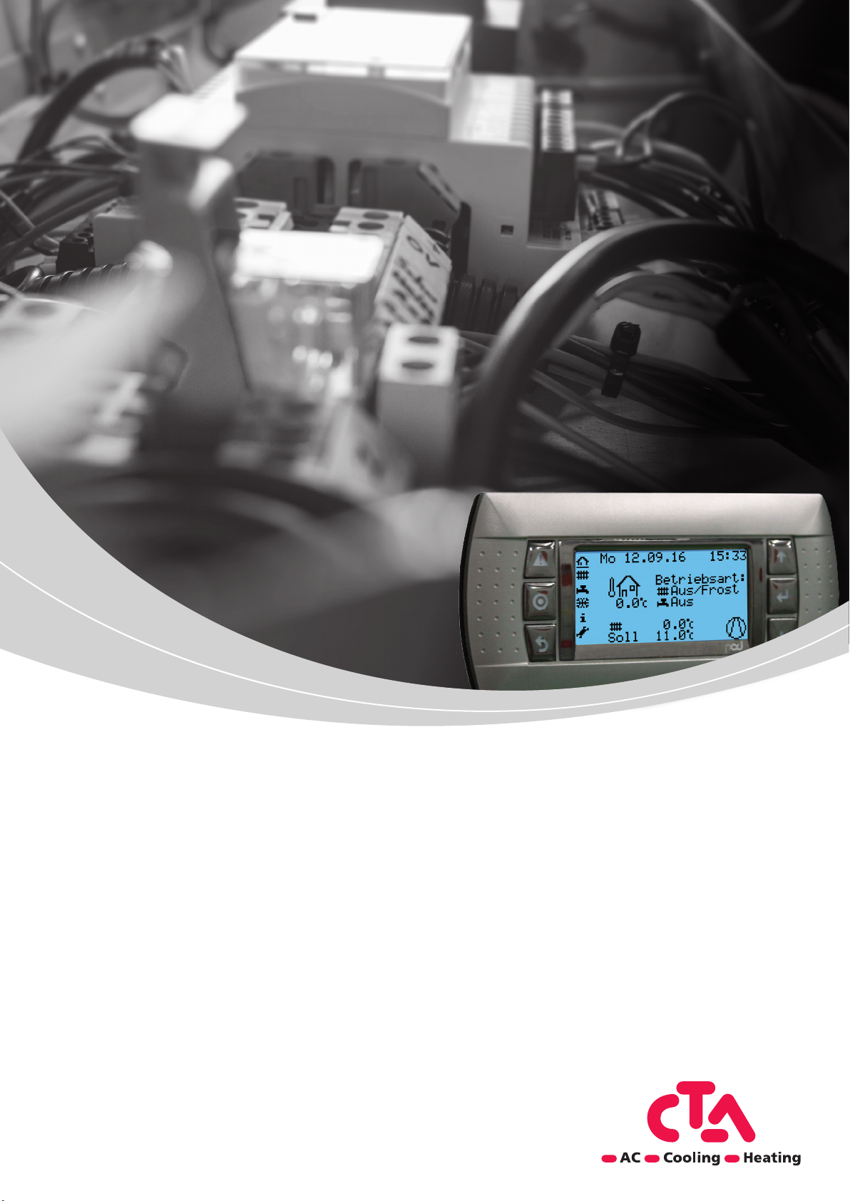
Operating manual
Optiplus 3
Heat pump controller
Page 2
No. Description Default
Cooling circuit 1
6
Operating mode CC1 -
Phase 1 On (Hours)
Operating mode CC1 -
KK101 Operating mode CC1 Off
KK102
22
0
Phase 1 On (Minutes)
Operating mode CC1 -
KK103
0
22
Phase 1 Off (Hours)
Operating mode CC1 -
KK104
4
0
Phase 1 Off (Minutes)
KK105
KK110 Room setpoint CC 1 24
0
20
Flow setpoint CC1 at 25°C
outside temperature
KK115
Flow setpoint CC1 at 35°C
6
18
outside temperature
KK116
KK117 Cooling limit CC1 at AT 24
Off
DHW charging nominal set-
point - Phase 1 On (Hours)
DHW charging nominal set-
point - Phase 1 On (Minutes)
DHW charging nominal set-
No. Description Default
TW101 Operating mode DHW Off
TW102
GK002 Setting time zone Bern
TW103
No. Description Default
Heating circuit 1
Frost pro-
HK101 Operating mode HC1
Domestic hot water
No. Description Default
Basic settings
GK001 Language Setting German
point - Phase 1 Off (Hours)
DHW charging nominal set-
point - Phase 1 Off (Minutes)
TW104
TW105
6
tection (Off)
Comfort mode HC1 -
Phase 1 On (Hours)
HK102
Domestic water re-charge
hysteresis
TW112
22
Phase 1 Off (Hours)
Comfort mode HC1 -
HK104
TW113 Legionella temperature 60
0
Phase 1 Off (Minutes)
HK105
TW110 Nominal setpoint DHW 51
TW111 Reduced setpoint DHW 40
0
Comfort mode HC1 -
Phase 1 On (Minutes)
Comfort mode HC1 -
HK103
Activation of the legionella
program
TW115
HK110 Comfort setpoint HC1 20
TW116 Legionella program day Fridays
Frost protection setpoint
HK111 Reduced setpoint HC1 19
TW117 Legionella program start time 2
10
HC1
HK112
HK113 Slope heating curve HC1 0.8
HK114 Offset heating curve HC1 0
Heating limit heating circuit 17
HK115
2 Subject to technical changes © CTA 10/2016 www.cta.ch
Page 3
User
Settings for specialist personnel
TW115
TW116
TW117
TW101
TW102
TW103
TW104
TW105
TW110
TW111
TW112
TW113
HK113
HK114
HK115
HK101
HK102
HK103
HK104
HK105
HK110
HK111
HK112
Specialist
1
Home
1
Software
and OS
Version
Controller
type
2
GK001
GK002
4
Password
entry
3
Date
Time
3 Sec.
1
65
4
3
1
2
3
1
2
3
1
2
TW015
TW016
TW017
KK101
KK102
KK103
KK104
KK105
KK110
3
1
2
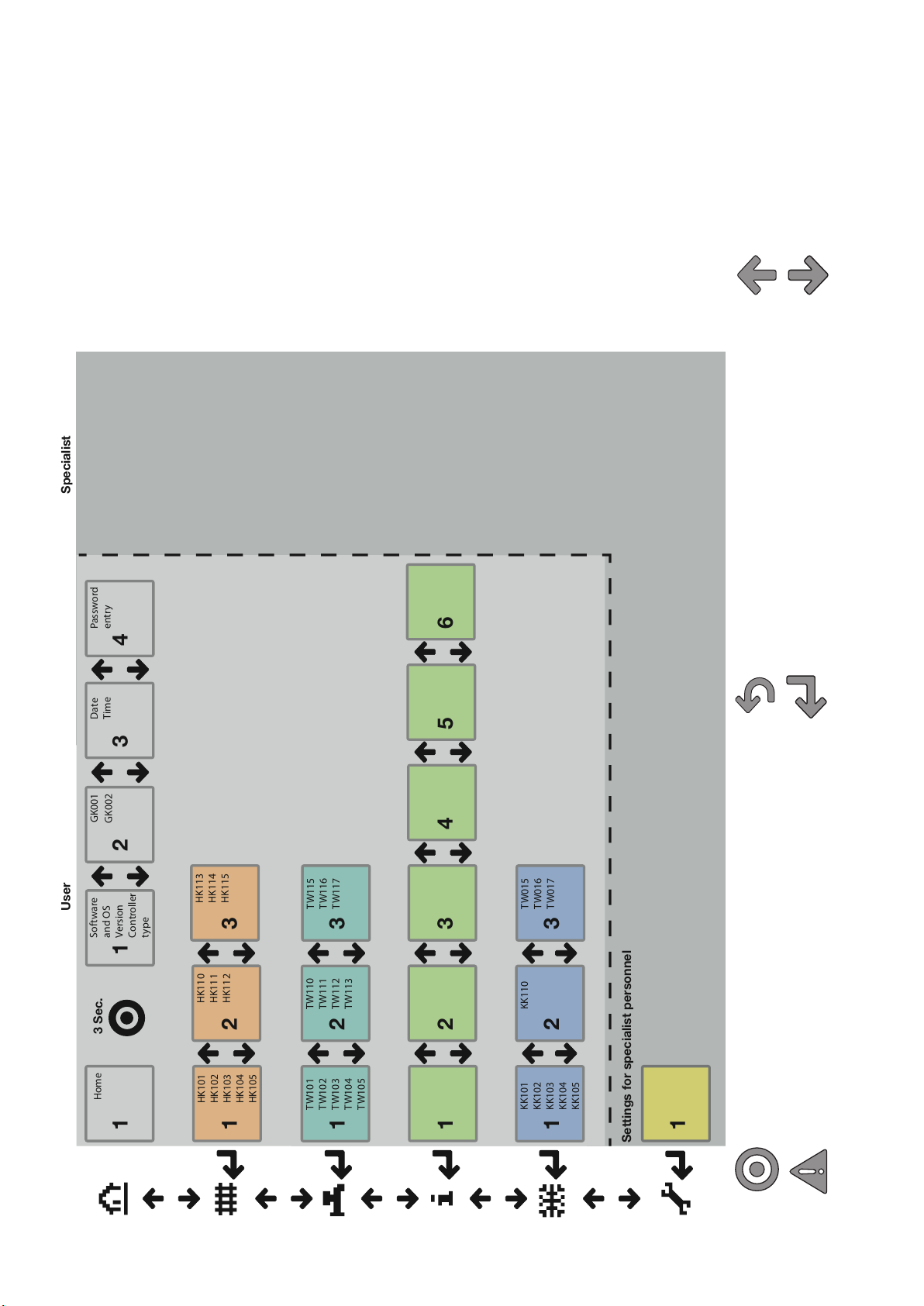
Arrow Up – Scroll back as
well as increase values.
Arrow Down – Scroll forwards
as well as reduce values.
Esc/Back – Cancel entries as well as back to the
previous level.
Enter/Confirm – Selection of parameters, confirming
entries as well as calling up selected levels.
Alarm key – Flashes when alarm is activated. Press in order to
Program key – Returns to the start screen from any level.
(Key pressed for 3 seconds: Basic settings / Password entry)
access the alarm description and to RESET the alarms.
3Subject to technical changes © CTA 10/2016 www.cta.ch
Page 4

Copyright and disclaimer
Copyright
Kindly read this first
This operating manual gives you important information about handling the unit. It is a part of the product and must
be kept ready to hand right next to the unit. It must be kept available during the entire life of the unit. It must be
handed over to subsequent owners of the unit.
Read this operating manual before starting any work on and with the unit. Particularly the safety chapter. Follow all
instructions completely and absolutely.
This operating manual may perhaps include descriptions, which may appear to be incomprehensible and unclear.
For queries and doubts, contact the factory customer service or the concerned on-site partner of the manufacturer.
Since this operating manual has been prepared for several types of units, parameters applicable for the relevant unit
type must be complied with. The operating manual is solely intended for personnel dealing with the unit. Treat all
constituent parts confidentially.
They are copyright protected. They may not be reproduced, transmitted, copied, saved in electronic systems or
translated into another language either partially or completely without the written consent of the manufacturer.
© Bern CTA AG
Hunzikenstrasse 2
CH-3110 Münsingen
Telephone +41 (0)31 720 10 00
Fax +41 (0)31 720 10 50
[email protected]
www.cta.ch
Disclaimer
The manufacturer is not liable for damages on account of use contrary to the intended use. Liability of the manufacturer ceases furthermore:
if work is performed on the unit and its components contrary to the specifications in this operating manual.
if work is perfomed improperly on the unit and its components.
if work not described in this manual is performed on the unit and this is not expressly approved by the manufacturer
in writing.
if the unit or the components in the unit are modified, retrofitted or dismounted without the express written consent
of the manufacturer.
4
Subject to technical changes © CTA 10/2016 www.cta.ch
Page 5
Table of contents
1 Safety 6
1.1 Classification of risks 6
1.2 Symbols used 6
1.3 Summary of risks 7
2 Intended use 8
2.1 Operation 8
2.2 Intended purpose 8
2.3 Customer service 8
2.4 Warranty / Guarantee 8
2.5 Disposal 9
2.6 Care of the unit 9
2.7 Maintenance of the unit 9
3 Basic information on operation 10
3.1 Control unit and keys 10
3.1.1 Start screen 11
3.1.2 General navigation 12
3.1.3 Change parameters 12
3.2 Heating mode 13
3.2.1 Operating mode Heating circuit 1 13
3.2.2 Heating circuit setpoint 14
3.2.3 Heating circuit heating curve 15
3.3 Domestic hot water mode 18
3.3.1 Operating mode DHW 18
3.3.2 Setpoints 20
3.3.3 Legionella program 20
3.4 Cooling mode 21
3.4.1 Operating mode Cooling circuits 21
3.4.2 Cooling circuit setpoints 22
3.4.3 Cooling characteristic curve 23
3.4.4 Cooling limit 23
3.5 Information 24
3.6 Settings 25
3.7 Error messages 25
3.7.1 Reset faults 25
3.7.2 Summoning the service organisation 25
3.8 Further functions 26
3.8.1 Software / regulation 26
3.8.2 Languages 26
3.8.3 Time, date and network information 26
3.8.4 Service level 26
4 Index 27
5Subject to technical changes © CTA 10/2016 www.cta.ch
Page 6
1 Safety
The unit is safe to operate when operated in accordance with its designated use. Design and execution of the unit complies with the current state of the art, all relevant EN regulations and all relevant safety regulations.
Each person working on the unit must have ready and understood the operating manual prior to starting work. This
also applies to persons who have already worked on such or similars units or have been trained by the manufacturer.
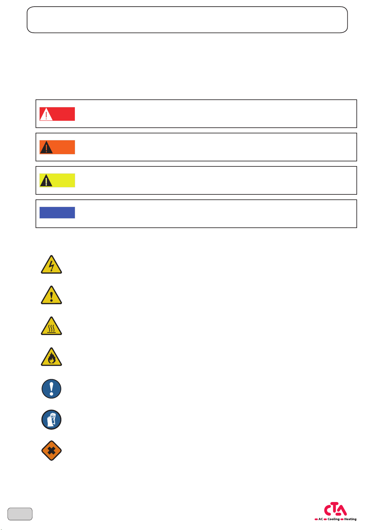
1.1 Classification of risks
DANGER
WARNING
CAUTION
NOTICE
1.2 Symbols used
This symbol warns of risk from dangerous electric voltage.
Increased
This symbol warns of dangers, non-compliance of which may lead to extensive property damage.
DANGER TO LIFE due to electric shock.
For imminent danger, which may lead to severe bodily injuries or death.
For a potentially dangerous situation, which may lead to severe bodily injuries or death.
For a potentially dangerous situation, which could lead to severe bodily injuries or death. May also be
used as warning for property damages.
For a potentially harmful situation.
Indicates important features for proper handling of the system.
This symbol warns of burns and scalds.
This symbol indicates inflammable substances.
This symbol shows tips and information for optimum use of the system.
This symbol indicates risk of injury to hands.
This symbol indicates substances harmful to health.
6
Subject to technical changes © CTA 10/2016 www.cta.ch
Page 7
Safety
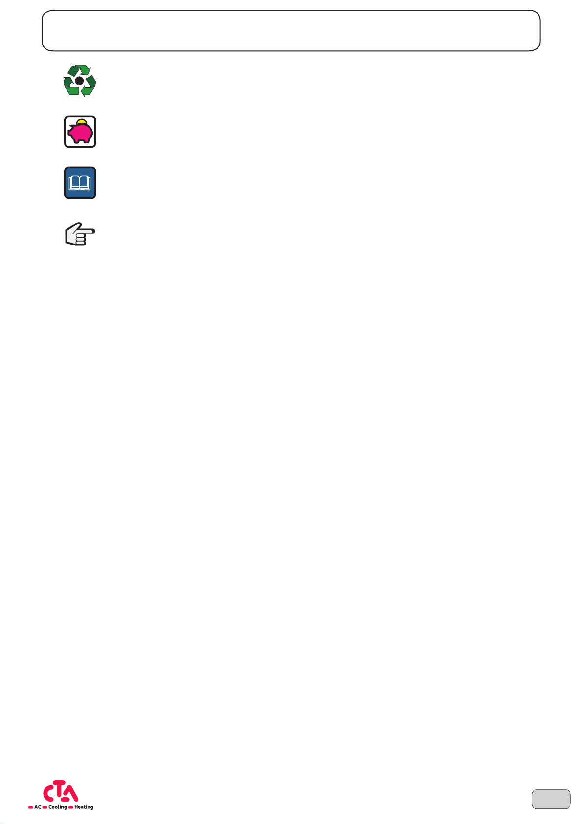
This symbol indicates reuse and disposal of the unit.
This symbol is for advice which help save energy, raw materials and costs.
This symbol refers to other documents of the manufacturer.
This symbol refers to other sections in the operating manual.
1.3 Summary of risks
Safety guidelines stated here cover all important topics. Therefore, read the manual carefully and attentively.
All actions described in this manual must be performed by a technician according to the applicable legislation.
Wear appropriate protective equipment (safety gloves, safety goggles, etc.) when performing work related to instal-
lation, maintenance or servicing of the unit.
If you have queries related to the installation procedure or operation of the unit, contact your local dealer for advice
and information.
Improper installation or placement of the unit or accessories may lead to electric shock, short circuit, leakages, fire
and other damages. Use only accessories and optional equipment from CTA, which are specially developed for use
with the products, which are the subject of this manual and have these installed by a installer.
7Subject to technical changes © CTA 10/2016 www.cta.ch
Page 8
2 Intended use
CAUTION
2.1 Operation
The existing manual serves correct installation and setting of the heat pump.
Likewise, this manual serves as a basis for the guarantee terms to be complied with by the operator, which is a
requirement for maintenance-free operation.
On violating the guarantee terms and after expiration of the guarantee period, the manufacturer of the heat pumps
does not undertake any responsibility for electrical defects. Guarantee lapses in case of interventions not explicitly
authorised and performed in violation of the existing manual. In-house safety regulations apply during the installation.
The existing manual and the connection of the terminal plan of the heat pump are to be preserved with due diligence and provided to the specialist personnel if required.
For all types of repair works, the operator of the heat pump is instructed to contact his specialist partner, who appoints a technical customer service authorised by the manufacturer for the servicing of the heat pump.
Non-compliance of the above stated information may adversely affect the safety of the unit.
CAUTION!
The manufacturer does not undertake any liability for personal injury or property damage resulting due to direct
or indirect non-compliance of the existing manual.
2.2 Intended purpose
The unit must be used for the intended purpose only. That means in conjunction with a heat pump Optiheat Inverta:
for controlling and monitoring the heat pump
for regulating the heating groups
for regulating the hot water preparation
The unit must be operated only within its technical parameters.
2.3 Customer service
For technical information, kindly contact your expert technician or the concerned on-site partner of the manufacturer.
2.4 Warranty / Guarantee
Warranty provisions and guarantee terms are in your purchase documents.
8
Subject to technical changes © CTA 10/2016 www.cta.ch
Page 9
Intended use
CAUTION
2.5 Disposal
CAUTION!
Reuse / disposal
When decommissioning the old unit on-site, comply with the applicable guidelines and standards for recycling,
reuse and disposal.
2.6 Care of the unit
You can use a damp cloth and standard cleaning products to clean the outer surfaces of the unit.
Do not use cleaning or care products that contain abrasives, acids and/or chlorine. Such products would irreparab-
ly damage the surfaces and could also cause technical damage to the unit.
2.7 Maintenance of the unit
The heating and heat pump controller requires no regular maintenance.
9Subject to technical changes © CTA 10/2016 www.cta.ch
Page 10

3 Basic information on operation
3.1 Control unit and keys
CTA controller with following features
• Display lights up, for status and function display
• Presetting standard program, setpoint, date, time
• Automatic switching between summer / winter time
• Preset standard time program for heating and domestic hot water preparation
• Complete controlling and monitoring of theheat pump including domestic hot water in one device
• Info page for quick request of themost important temperature and system states
• Integrated operating hours counter
• Thermal disinfection of domestic hot water (legionella mode)
• Probe protection function
• Emergency operation and frost protection function
• Configuration menu for all established hydraulic controls
• Guided commissioning assistance
• Browser-based configuration tool
• Continuous recording (data log) of the most important operating parameters for service and maintenance, as
well as operation analysis
Legend for abbreviations:
HP Heat pump BC Basic configuration
EW Electric utility Eco Protection functions activated
HC Heating circuit DHW Domestic hot water
CC Cooling circuit
Display
Alarm key – Flashes when alarm is activated. Press in order to access the alarm description and to
RESET thealarms.
10
Program key Start screen – Returns to thestart screen from any level.
(Key pressed for 3 seconds: Basic settings / Password entry)
Esc / Back – Cancel entries as well as back to the previous level.
Arrow Up – Scroll back as well as increase values.
Enter / Confirm – Selection of parameters, confirming entries as well as calling up levels previously selected using thearrow keys.
Arrow Down – Scroll forwards as well as reduce values.
Subject to technical changes © CTA 10/2016 www.cta.ch
Page 11
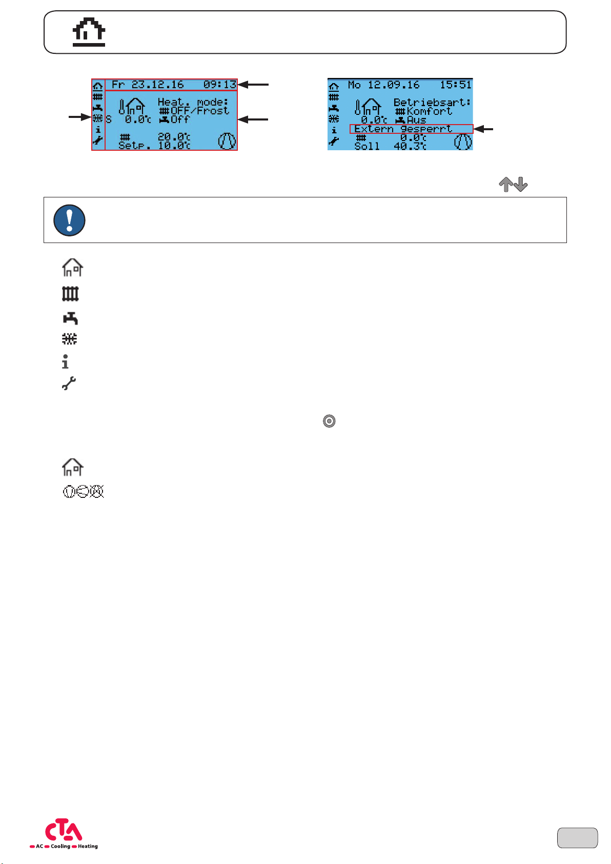
3.1.1 Start screen
Basic information on operation
2
1
1: Navigation bar
The navigation bar can be used to access the main operating levels displayed using the arrow keys.
3
NOTE The levels „Information“ and „Settings“ are protected by password in some cases and can only
be accessed by qualified specialist personnel.
Start screen
Heating mode
Domestic hot water mode
Cooling mode
Information
Settings
2: Date & Time
4
The current settings can be adapted using the Program key
3: Status display
Outside temperature
Compressor status (ON/OFF/Blocked)
Outside temperature
- The current outside temperature, measured using theexternal sensor
Operating mode Heating / DHW / Cooling
- The current active operating mode for theheating, DHW and cooling mode are displayed respectively
(keep pressed for 3 seconds).
11Subject to technical changes © CTA 10/2016 www.cta.ch
Page 12
Basic information on operation
Active priority control
NOTE Heating, DHW and cooling modes can never be carried out at thesame time. This symbol indi-
cates which mode is currently being operated.
- Heating symbol → Heating mode is active, water tap symbol → DHW mode is active or
cooling symbol → cooling mode is active
The current regulating temperature is displayed for this purpose
- Nominal: Current nominal temperature required from all active consumers
Compressor status
- The compressor symbol rotates
- The compressor symbol is stationary
→ The heat pump is in operation
→ The heat pump is not in operation
NOTE More displays for the current state are represented in the operating level „Information“.
4: External release
Draw wish / forced appears in case of increased heat demand. (Operation with SG Ready).
External blocked appears when, e.g., EW block is active. The compressor symbol is crossed-out
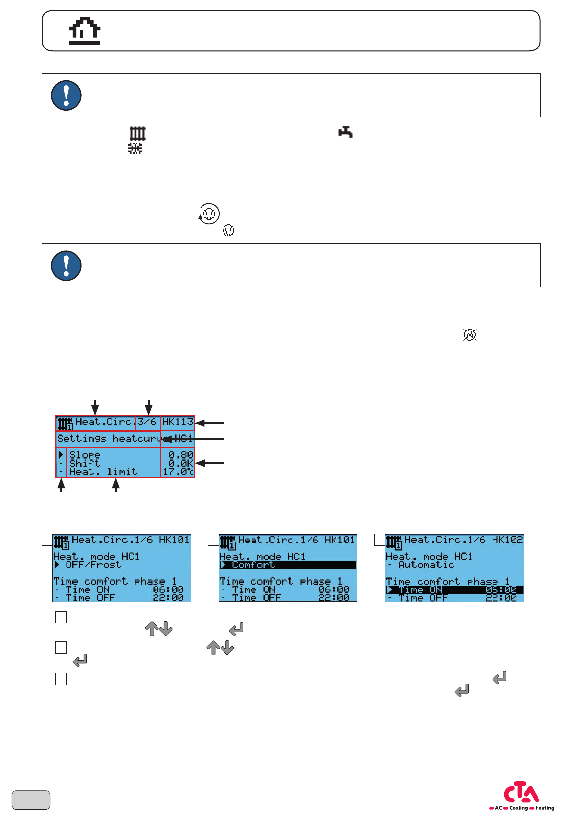
3.1.2 General navigation
1
5
6
2
3
4
7
1: Operating level
2: Current screen / number of screens on this level
3: Number of parameter selected
4: Umbrella term of theparameter of this mask
5: Parameter selection
6: Parameter designation (parameter selected, - parameter
that can be selected)
7: Parameter value
.
3.1.3 Change parameters
1 2 3
In order to change a parameter or the operating mode, this (these) must be selected on the respective mask
1
12
using the arrow keys
When pressing the arrow keys you can now change the functions or values. When pressing the Enter
2
key , changes are confirmed and the parameter is no longer highlighted black.
Several parameters such as, e.g., the time are changed in two steps. When pressing the Enter key , in
3
this case you access the hours and by pressing again, you access the minutes. Pressing Enter
completes the changes.
. Press Enter to select the parameter. This is then highlighted black.
Subject to technical changes © CTA 10/2016 www.cta.ch
for a third time
Page 13
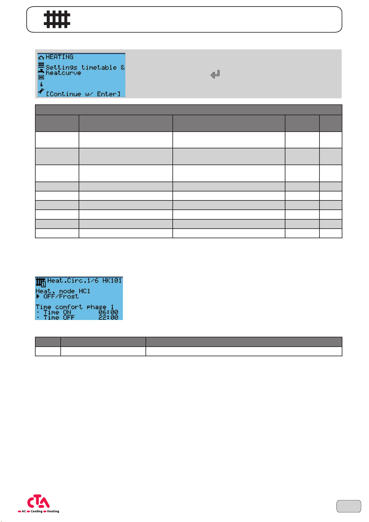
3.2 Heating mode
Heating circuits
No.* Screen display Description
HK101 Operating mode HC1 Operating mode heating circuit 1
HK102/HK103
HK104/HK105
HK110 Comfort setpoint HC1 Comfort setpoint heating circuit 1 20 °C
HK111 Reduced setpoint HC1 Reducted setpoint heating circuit 1 19 °C
HK112 Frost protection HC1 Frost protection setpoint heating circuit 10 °C
HK113 Slope heating circuit HC1 Slope heating curve heating circuit 0.8 HK114 Offset heating curve HC1 Offset heating curve heating circuit 0 K
HK115 Heating limit HC1 Heating limit heating circuit 17 °C
Hours/Minutes comfort phase 1 -
Hours/Minutes comfort phase 1 -
Basic information on operation
In the chapter Heating you can change between the individual operating
modes, set the time program as well as carry out settings to the heating
curve. Using the ENTER key , you can access the parameters that can
be edited. These settings can be carried out for all available heating circuits
separately.
Comfort mode heating circuit 1 -
On HC1
Comfort mode heating circuit 1 -
Off HC1
Phase 1 On
Phase 1 Off
Default
value
Frost protection
(Off)
06:00 h/min
22:00 h/min
Unit
-
* HK1xy = Heating circuit 1, HK2xy = Heating circuit 2, HK3xy = Heating circuit 3, ...
3.2.1 Operating mode Heating circuit 1
The operating mode and the time window of the comfort phase can be set in mask 1/6.
No. Screen display Description
HK101 Operating mode HC1 Operating mode heating circuit 1
You can select between the following operating modes:
Automatic mode (Auto):
Automatic mode regulates the room temperature according to the defined time window. Within the time window,
heating is carried out using the comfort setpoint (e.g., during the daytime) and outside the time window, using the
reduced setpoint (e.g., overnight).
Comfort or reduced mode:
These are continuous operating modes that keep the room temperature constant at the level selected. This is either
the comfort or reduced setpoint. No time program is active.
Off / Frost (Protective mode):
In Off / Frost mode, the heater is switched off. However, it remains protected against frost (frost protection temperature, factory setting +10°C), whereby the voltage supply must not be interrupted.
13Subject to technical changes © CTA 10/2016 www.cta.ch
Page 14

NOTICE
15
16
17
18
19
20
21
22
23
24
Time
Phase 1 ON
Phase 1 OFF
Phase 1 ON
Phase 1 OFF
Basic information on operation
NOTE The Eco function is switched into automatic mode automatically when the device switches to
summer mode. (Operating mode Eco, Summer and Off / Frost (Protective mode) are identical.
Heating emergency mode:
In event of operational interruptions, theheat pump can be operated using an additional heat generator. The emergency
mode is regulated to thecurrent setpoint according to theheating curve set.
NOTE If emergency mode is demanded without valid electric heating element, an alarm message is
displayed and operation is interrupted.
WARNING!
Your heating installer must be informed when you are using the emergency mode.
No. Screen display Description
HK102/HK103 Hours/Minutes comfort phase 1 - On HC1 Comfort mode heating circuit 1 - Phase 1 On
HK104/HK105 Hours/Minutes comfort phase 1 - Off HC1 Comfort mode heating circuit 1 - Phase 1 Off
These parameters define thetime window for thecomfort phase in automatic mode (see graphic below).
3.2.2 Heating circuit setpoint
No. Screen display Description
HK110 Comfort setpoint heating circuit 1 Set the setpoint during the comfort phase
HK111 Reduced setpoint heating circuit 1 Set the setpoint outside the comfort phase (reduced value)
HK112
Frost protection setpoint heating
circuit
[HK002/HK003]
Set the frost protection value when the heating mode is switched off
[HK004/HK005]
[HK002/HK003]
[HK004/HK005]
14
T [°C]
Comfort setpoint
[HK010]
06:0000:00 06:0022:00 22:00
Subject to technical changes © CTA 10/2016 www.cta.ch
Reduced setpoint
[HK011]
Comfort setpoint
[HK010]
Page 15
Basic information on operation
3.2.3 Heating circuit heating curve
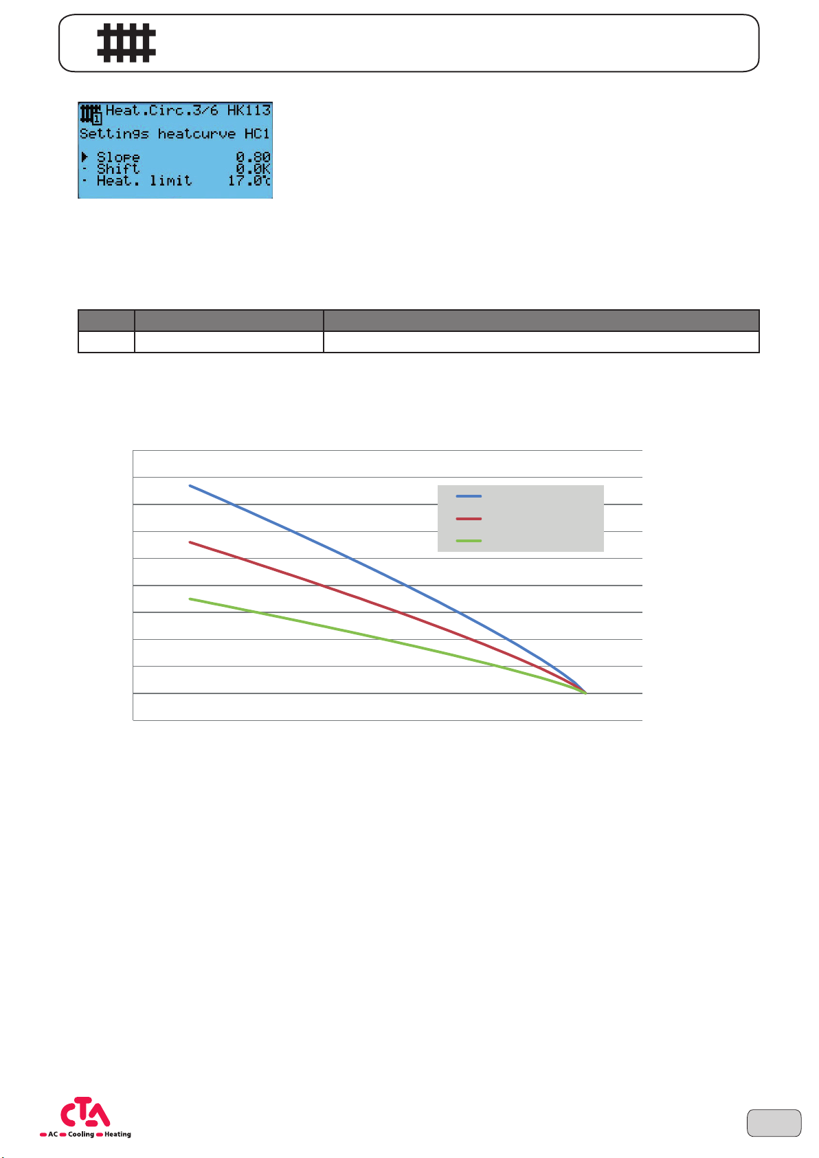
The setpoint for the heating flow is calculated using the current outside temperature and the set heating characteristic curve. Now the flow temperature of the heating circuit should be regulated to this setpoint. The heating
characteristic curve can be adapted so that the heating output and therefore room temperature act according to
your personal requirements. This is carried out in mask 3/6.
No. Screen display Description
HK113 Slope heating curve HC1 Slope characteristic curve
The flow temperature changes more stronger with the slope, the lower the outside temperature is. A crucial factor
for the optimum value of the slope are the building shell and type of heating. The better the building shell and more
efficient the heating, the lower the slope can be set. The following graphic indicates this:
65
60
VL (Slope 1.1)
55
50
45
40
35
30
25
Flow temperature in°C
20
15
-20 -15 -10 -5 0 5 10 15 20 25
VL (Steigung 1.1)
VL (Slope 0.8)
VL (Steigung 0.8)
VL (Slope 0.5)
VL (Steigung 0.5)
Outside temperature mixed in°C
Example:
- Slope 0.5 (e.g. new building)
In the graphic, you can find three exemplary curves at 20°C outside temperature at the same point. The lower the
outside temperature drops, the flow temperature generated that has to be provided by the heat pump is higher depending on the slope. The more efficient the heating system is, the lower the flow temperature can be, and therefore also the slope. The room temperature, however, remains the same in all three cases.
15Subject to technical changes © CTA 10/2016 www.cta.ch
Page 16
Basic information on operation
No. Screen display Description
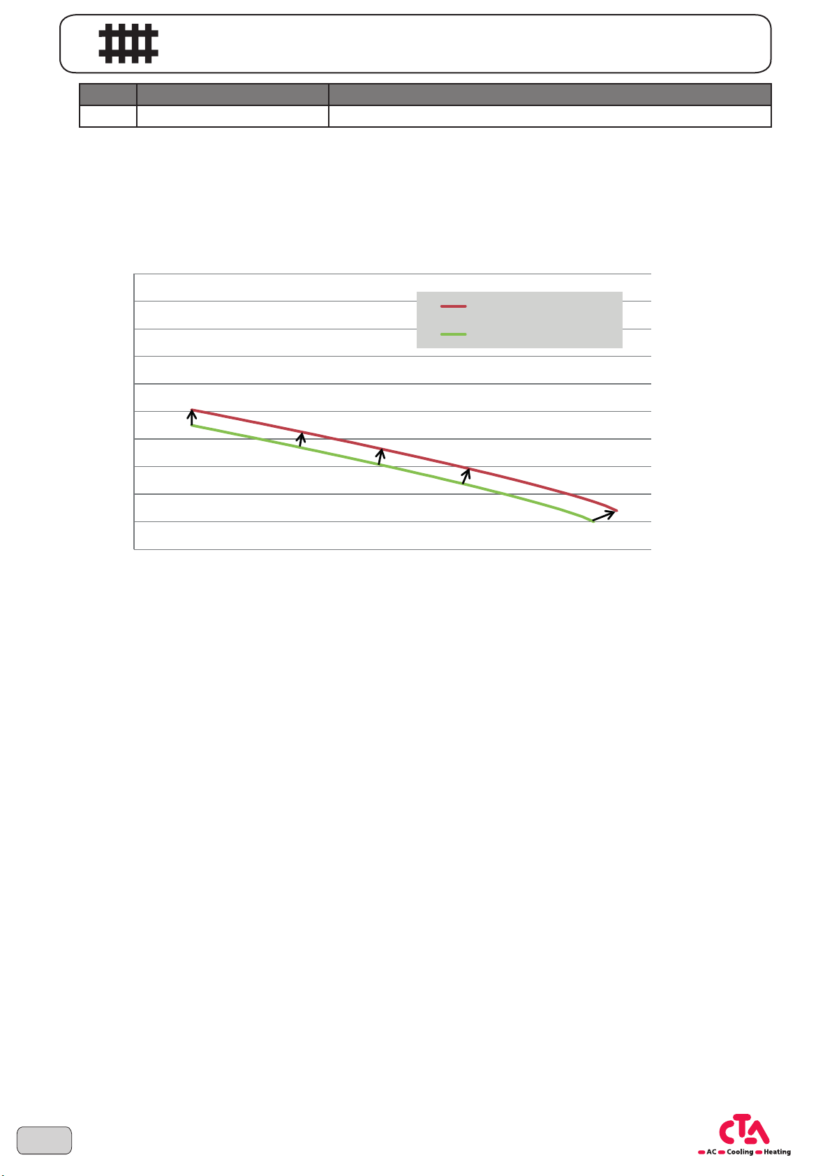
HK114 Shift heating curve HC1 Characteristic curve shift
If the room temperature is generally too warm or too cold, this can be corrected by a parallel shift.
Example:
If the comfort setpoint is set to 22°C and only 20°C is always measured in the room, this deviation can be corrected by increasing the parameter shift (HK114) by 2K. Now the effective room temperature corresponds with the set
comfort setpoint.
65
60
55
50
45
40
35
30
25
Flow temperature in°C
20
15
-20 -15 -10 -5 0 5 10 15 20 25
Comfort setpoint 22°C
Komfortsollwert 22°C
Komfortsollwert 20°C
Comfort setpoint 20°C
Outside temperature mixed in°C
If the effective room temperature deviates even more from the set comfort setpoint the lower the outside temperature drops, the slope (HK113) can easily be adapted in the direction required.
16
Subject to technical changes © CTA 10/2016 www.cta.ch
Page 17
Basic information on operation
No. Screen display Description
HK115 Heating limit HC1 Heating limit
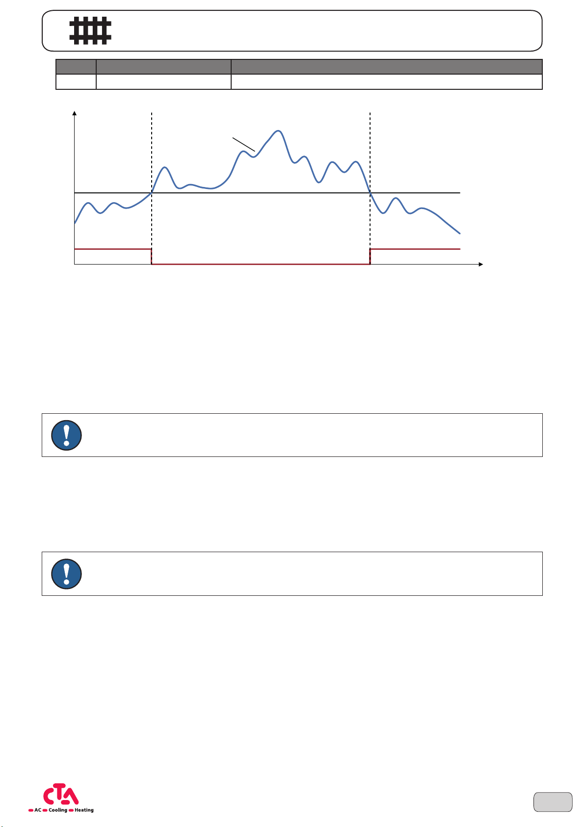
Where required, the heating limit can be edited via parameter HK115.
24
23
T [°C]
22
21
20
19
18
17
16
15
ON
OFF
Averaged outside
temperature (Ø 24h)
Heating limit [HK015]
Summer / Winter
Time
T Outside temperature in °C
ON Heating On => Winter
OFF Heating Off => Summer
Example (see graphic above):
From an outside temperature of 17°C, the heating limit has exceeded and the device runs in Eco mode and does
not heat. If the averaged otuside temperature drops below 17°C over the last 24 hours, the device switches back
to winter mode and starts to heat.
NOTE Wait at least 2 hours after each correction so that the room temperature can be adapted.
Summer / winter time switchover:
The function summer / winter time switchover switches the heating off if the averaged outside temperature exceeds
the set heating limit. The heating switches back on once the averaged outside temperature falls below the switching temperature.
In summer mode, the heating automatically switches to protective mode. The symbol ECO appears on the display.
The domestic hot water production is still guaranteed.
NOTE The summer / winter time switchover functions only in automatic mode. „Eco/Summer“ appears in
the display. The outside temperature is averaged to consider the dynamics of the building.
17Subject to technical changes © CTA 10/2016 www.cta.ch
Page 18
Basic information on operation
3.3 Domestic hot water mode
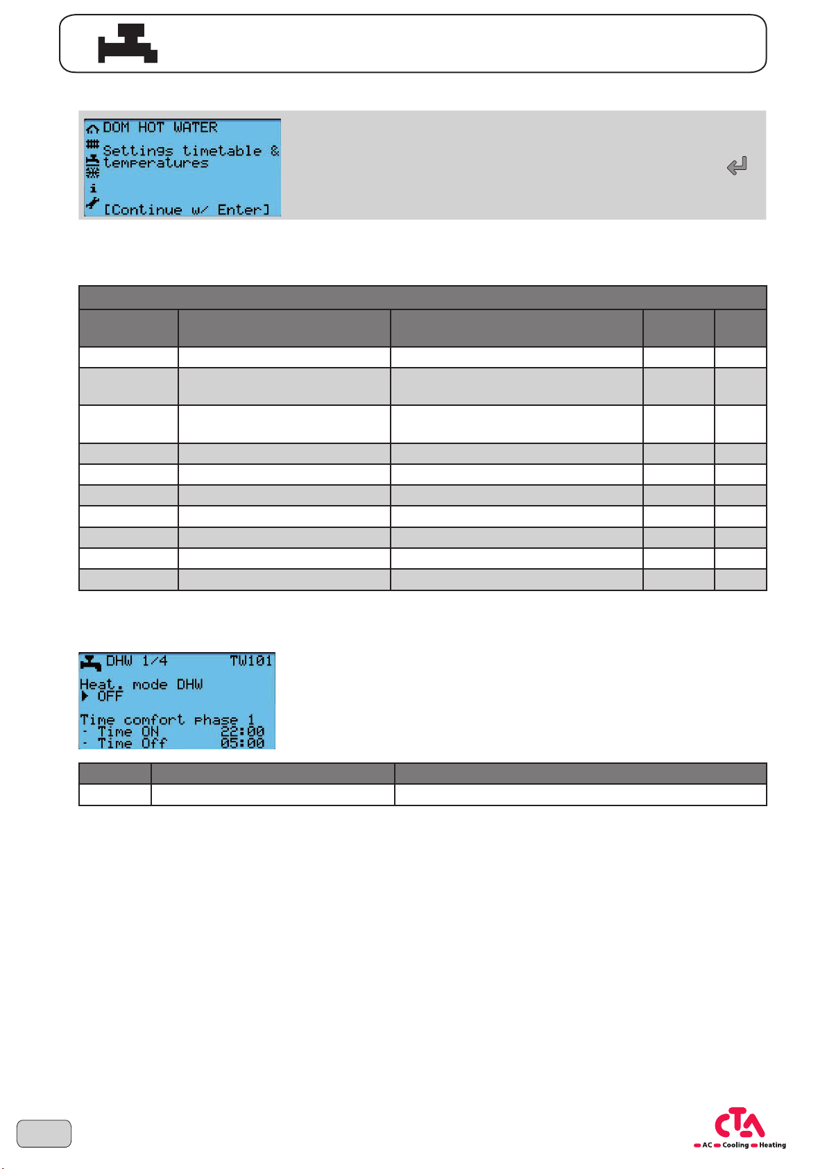
In the chapter Hot water you can switch on the domestic hot water
operating mode and define the time program. Using the ENTER key
you can access the parameters that can be edited.
When there is a demand for the domestic hot water charging, the heat pump is put into operation. This now heats
the domestic water to the desired setpoint. After reaching the setpoint, the heat pump switches off or, where required, to heating mode.
Domestic water
No. Screen display Description
TW101 Operating mode DHW Operating mode domestic water Off -
TW102/TW103
TW104/TW105
TW110 Nominal setpoint DHW Nominal setpoint domestic water 51 °C
TW111 Reduced setpoint DHW Reduced setpoint domestic water 40 °C
TW112 DHW hysteresis Domestic water re-charge hysteresis 6 K
TW113 Legio-temp. Legionella temperature 60 °C
TW115 Activation Activation of the legionella program Off TW116 Per. Legionella program day Fridays TW117 Charge from Legionella program start time 02:00 h
Hours/Minutes comfort phase 1 -
On DHW
Hours/Minutes comfort phase 1 -
Off DHW
DHW charging nominal setpoint -
Phase 1 On
DHW charging nominal setpoint -
Phase 1 Off
Default
value
22:00 h/min
04:00 h/min
,
Unit
3.3.1 Operating mode DHW
The operating mode and the time window of the comfort phase can be set in mask 1/4.
No. Screen display Description
TW101 Operating mode DHW Operating mode domestic water
You can choose between the following operating modes via parameter TW101:
Domestic water mode ON:
The domestic water mode heats according to a defined time window. Heating is carried out to the nominal setpoint
within the time window (e.g., overnight). The heating outside the time window is only carried out to the reduced
setpoint.
Domestic water mode OFF:
No domestic water preparation.
Domestic water Push (Domestic water – quick charging):
If the function is selected, an immediate heating of the domestic hot water is carried out to the configured legionella
temperature. After reaching the desired temperature, the operating mode is automatically reset to the last setting.
18
Subject to technical changes © CTA 10/2016 www.cta.ch
Page 19
NOTICE
Basic information on operation
NOTE A periodic heating to legionella temperature can be activated using the legionella program „3.3.3
Legionella program“ on page 20
No. Screen display Description
TW102/103
TW104/105
These parameters define the time window for the nominal setpoint in Domestic water mode ON.
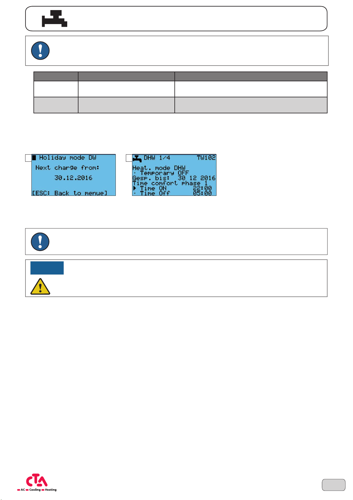
Operating mode temporarily OFF
With planned longer absence, the DHW mode can be switched off temporarily. Restoring the DHW mode is carried
out using the set date.
1 2
Hours/Minutes comfort phase 1 -
On DHW
Hours/Minutes comfort phase 1 - Off
DHW
Comfort phase DHW On
Comfort phase DHW Off
DHW emergency mode:
In event of operational interruptions, the heat pump can be operated using an additional heat generator. The emergency mode is regulated to the current setpoint according to the DHW setpoint set.
NOTE If emergency mode is demanded without valid electric heating element, an alarm message is
displayed and operation is interrupted.
WARNING!
Your heating installer must be informed when you are using theemergency mode.
19Subject to technical changes © CTA 10/2016 www.cta.ch
Page 20
40
45
50
55
65
Time
Phase 1 ON
Phase 1 OFF
Phase 1 ON
Basic information on operation
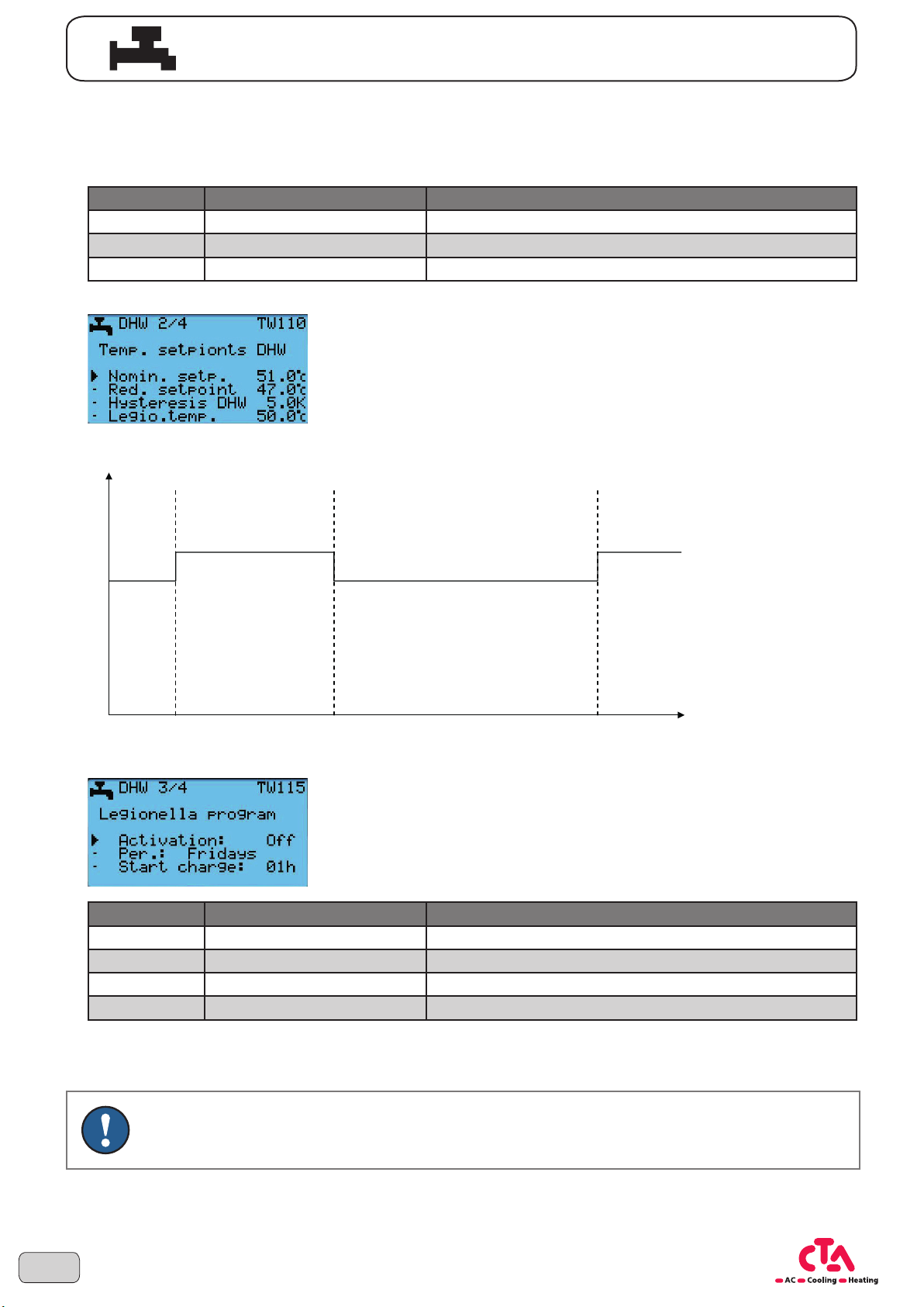
3.3.2 Setpoints
The domestic water can be conducted according to the nominal or reduced setpoint. These can be edited via
mask 2/4 and the parameters TW110 und TW111. The hysteresis (TW112) is the deviation that the domestic hot
water may have from the setpoint before the heat pump starts heating.
No. Screen display Description
TW110 Nominal setpoint DHW Nominal setpoint domestic water
TW111 Reduced setpoint DHW Reduced setpoint domestic water
TW112 DHW hysteresis Domestic water re-charge hysteresis
Example:
The device operates in reduced mode, 47°C is configured as reduced setpoint. Hot water is consumed, the temperature drops in the storage tank.
The hysteresis is set with 5K. The device therefore starts with the hot water
production as soon as the temperature in the storage tank falls below 42°C
(47°C – 5K = 42°C).
[TW002/TW003]
T [°C]
Nominal setpoint
[TW010]
20:00 20:0005:00
[TW004/TW005]
[TW002/TW003]
Reduced setpoint
[TW011]
3.3.3 Legionella program
No. Screen display Description
TW113 Legio-temp. Legionella temperature
TW115 Activation Activation of the legionella program
TW116 Per. Legionella program day
TW117 Charge from Legionella program start time
In the mask TWW 3/4, the legionella mode can be switched on or off as well as defined. If the activation is set to
ON (TW115), the heat pump heats the storage tank to the desired legionella temperature (TWW113) on the defined
week day or daily (TW116) at the selected time (TW117).
20
NOTE „Legio/act.“ appears in the display when legionella charging is active.
Subject to technical changes © CTA 10/2016 www.cta.ch
Page 21
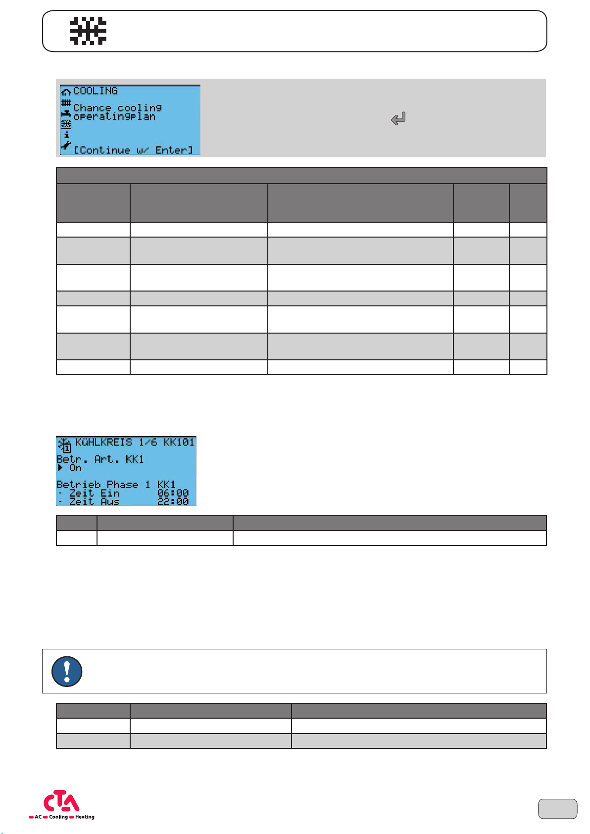
3.4 Cooling mode
Cooling circuits
Basic information on operation
In the chapter Cooling you can change between the inidivual operating
modes, set the time program as well as carry out settings to the cooling limit
and flow setpoints. Using the ENTER key , you can access the parameters that can be edited. These settings can be carried out for all available
cooling circuits separately.
No.* Screen display Description
KK101 Operating mode CC1 Operating mode cooling circuit 1 Off
KK102/KK103
KK104/KK105
KK110 Room setpoint CC1 Room setpoint cooling circuit 1 24 °C
KK115 Flow CC1 at 25°C AT
KK116 Flow CC1 at 35°C AT
KK117 Cooling limit CC1 Cooling limit cooling circuit 1 at AT 24 °C
* KK1xy = Cooling circuit 1, KK2xy = Cooling circuit 2, KK3xy = Cooling circuit 3, ...
Hours/Minutes phase 1 -
On CC1
Hours/Minutes phase 1 -
Off CC1
Operating mode cooling circuit 1 -
Phase 1 On
Operating mode cooling circuit 1 -
Phase 1 Off
Flow setpoint CC1 at 25°C outside
temperature
Flow setpoint CC1 at 35°C outside
temperature
Default
value
06:00 h/min
22:00 h/min
20 °C
18 °C
3.4.1 Operating mode Cooling circuits
The operating mode and the time window of the comfort phase in cooling mode can be set in mask 1/6.
Unit
No. Screen display Description
KK101 Operating mode CC1 Operating mode cooling circuit 1
You can select between the following operating modes:
On:
The cooling function is activated and regulates the cooling demand automatically according to the defined time
window, as soon as the day cooling limit is exceeded.
Off:
The cooling function is deactivated.
NOTE The regulation is only active during summer (Summer/Eco) or frost protection mode (Off/Frost) of
the heating operation.
No. Screen display Description
KK102/KK103 Hours/Minutes phase 1 - On CC1 Operating mode cooling circuit 1 - Phase 1 On
KK104/KK105 Hours/Minutes phase 1 - Off CC1 Operating mode cooling circuit 1 - Phase 1 Off
These parameters define the time window for the the comfort phase in cooling mode.
21Subject to technical changes © CTA 10/2016 www.cta.ch
Page 22
Basic information on operation
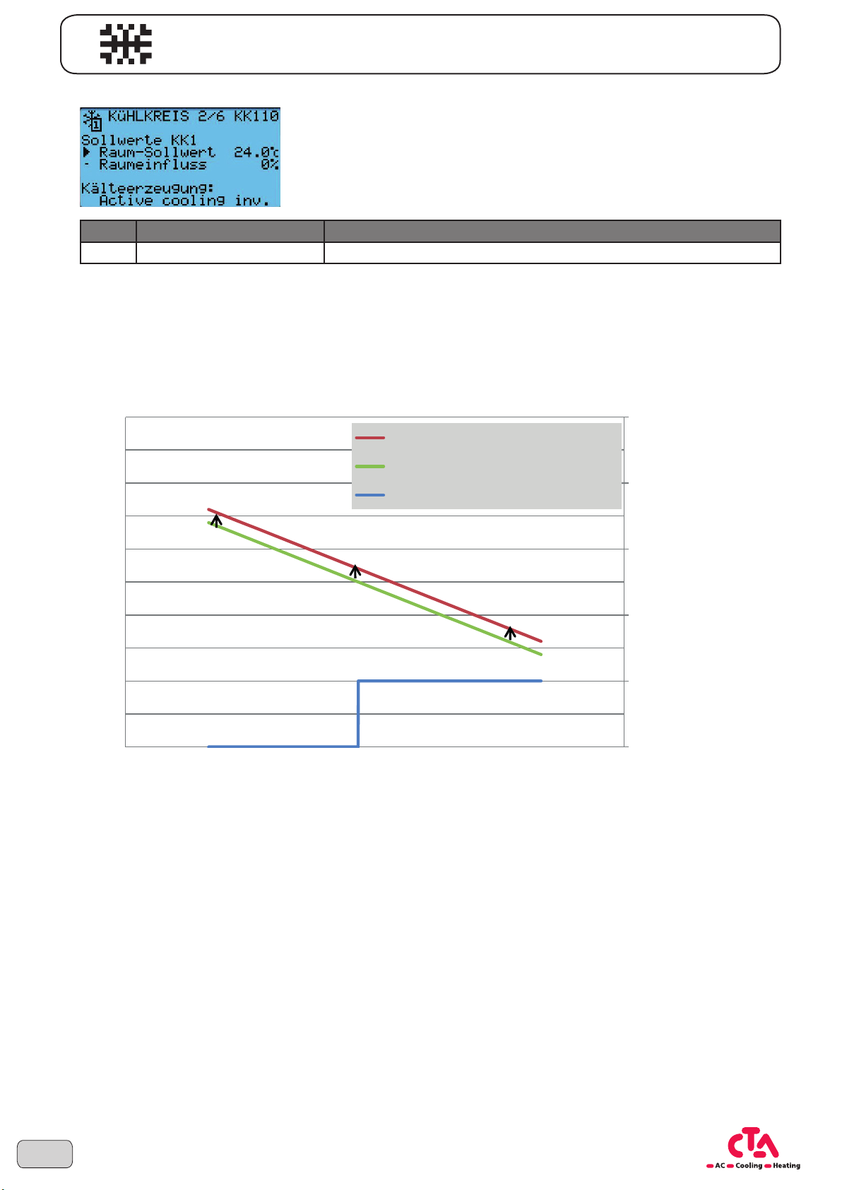
3.4.2 Cooling circuit setpoints
No. Screen display Description
KK110 Room setpoint CC1 Room setpoint cooling circuit 1
Example:
If the comfort setpoint is set to 22°C and only 20°C is always measured in the room, this deviation can be corrected by increasing the parameter shift (HK114) by 2K. Now the effective room temperature corresponds with the set
comfort setpoint.
with cooling characteristic curve KK115 20°C, KK116 16°C and cooling limitation 24 °C
30
Room setpoint (KK110) 26°C
28
26
24
Raumsollwert (KK110) 26°C
Room setpoint (KK110) 24°C
Raumsollwert (KK110) 24°C
Betriebsart Kühlkreis (KK101) Ein
Operating mode cooling circuit (KK101) On
22
Minimalbegrenzung
Minimum limit
20
18
16
14
Flow temperature in°C
12
10
10 15 20 25 30 35 40
Outside temperature mixed in°C
With the cooling function being set, the cooling demand is determined according to the mixed outside temperature. The cooling mode is activated when exceeding the set cooling limit (KK117). The operating mode is regulated
based on the current setpoint temperature in the cooling circuit. The setpoint cooling circuit is determined with the
following setting parameter depending on the outside temperature.
Cooling limit
Kühlgrenze
aktiv
active
22
Subject to technical changes © CTA 10/2016 www.cta.ch
Page 23
NOTICE
Basic information on operation
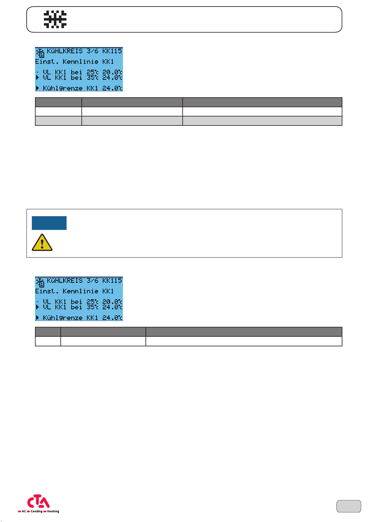
3.4.3 Cooling characteristic curve
No. Screen display Description
KK115 Flow CC1 at 25°C AT Flow setpoint CC1 at 25°C outside temperature
KK116 Flow CC1 at 35°C AT Flow setpoint CC1 at 35°C outside temperature
The cooling setpoint depending on the outside temperature is defined with the setpoints at an outside temperature
of 25°C and 35°C. The cooling characteristic curve is adjusted with the room setpoint and is limited by the defined
minimum characteristic curve to avoid formation of condensation.
Flow setpoint at 25°C AT
Determines the flow temperature required for cooling at a mixed outside temperature of 25°C.
Flow setpoint at 35°C AT
Determines the flow temperature required for cooling at a mixed outside temperature of 35°C.
WARNING!
The setting of the minimum cooling characteristic curve must be adjusted by specialist personnel.
The responsibility for protection from damages due to formation of condensation must be assumed
by the appropriate installer.
3.4.4 Cooling limit
No. Screen display Description
KK117 Cooling limit CC1 Cooling limit cooling circuit 1 at AT
The cooling mode is activated above the cooling limit temperature and regulates the required flow temperature for
the appropriate cooling circuit. The cooling limit is compared with the mixed outside temperature. The cooling limit
must be higher than the summer/winter switchover temperature.
Increasing the cooling limit
• Later switchover to cooling mode
• Earlier switchover to cooling mode off
Lowering the cooling limit
• Earlier switchover to cooling mode
• Later switchover to cooling mode off
23Subject to technical changes © CTA 10/2016 www.cta.ch
Page 24
Basic information on operation
3.5 Information
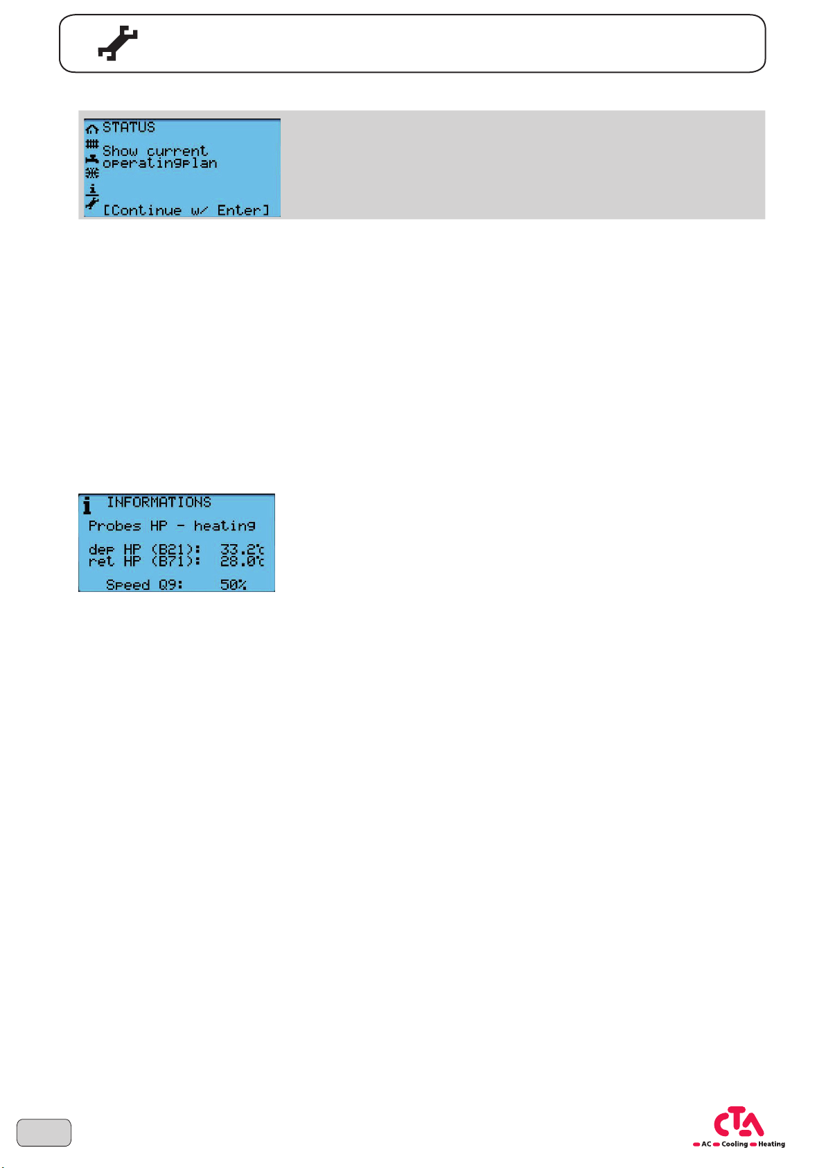
The current measurement or setting values of diverse parameters can be
read from the level „Information“. The level is only for displaying, parameters cannot be edited.
The following items can be viewed under „Information“:
• Sensor HP heating circuit
• Sensor HP source and minimum source temperature since commissioning
• Domestic hot water
• Buffer storage
• State circulation pumps and flow
• if available: Mixer groups and heating buffer
• Operating hours, number of starts and speed range compressor
• Optional: if energy meter available, energy meter and performance factor
Example: Flow and return temperature of the heating
24
Subject to technical changes © CTA 10/2016 www.cta.ch
Page 25
Basic information on operation
NOTICE
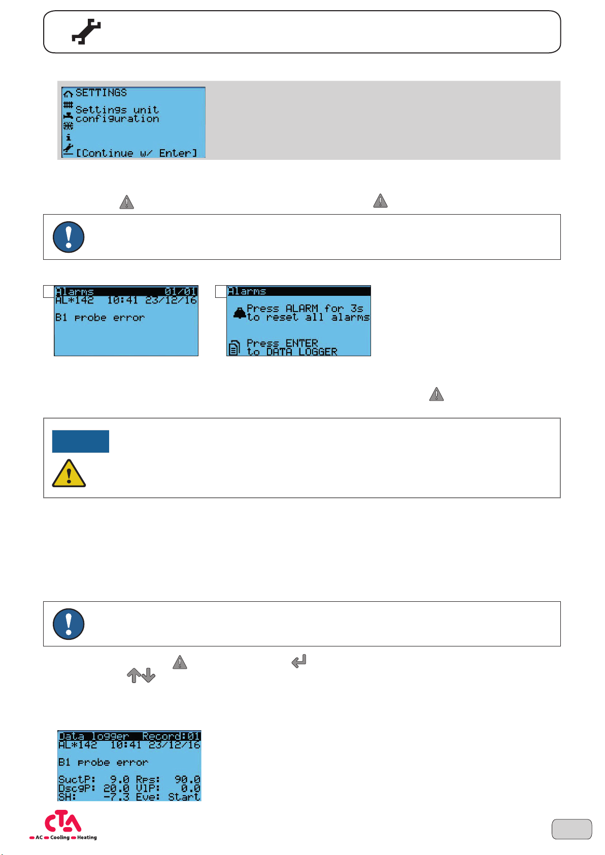
3.6 Settings
Via the level settings, those parameters can be edited that are mainly
required for the commissioning or in special cases.
The level settings can only be accessed by specialist personnel.
3.7 Error messages
If the alarm key flashes, there is a system error present. Press the alarm key and read the further details.
NOTE Some alarm messages are reset automatically and are recorded accordingly with an entry in the
alarm memory.
Example:
1 2
3.7.1 Reset faults
Error messages of the heat pump can be reset or acknowledged using the alarm key . Pressing the key for longer than 3 seconds triggers a RESET of the heat pump.
WARNING!
If an alarm cannot be acknowledged or reoccurs again after a short period, the responsible service
organisation must be summoned in all cases.
3.7.2 Summoning the service organisation
Before calling the service organisation / customer services, note the following items:
• Serial number
• Error number and error designation
• Pressure from the heat source and heating system (pressure gauge)
NOTE First always refer to your heating installer.
By pressing the alarm key and then the Enter key , alarms that have already triggered can be called up.
The arrow keys
the alarm, the number of occurring alarms (record) as well as several parameter values at the time of the alarm are
displayed.
can be used to scroll through the different alarms. The alarm designations, date and time of
Example:
25Subject to technical changes © CTA 10/2016 www.cta.ch
Page 26
Basic information on operation
3.8 Further functions
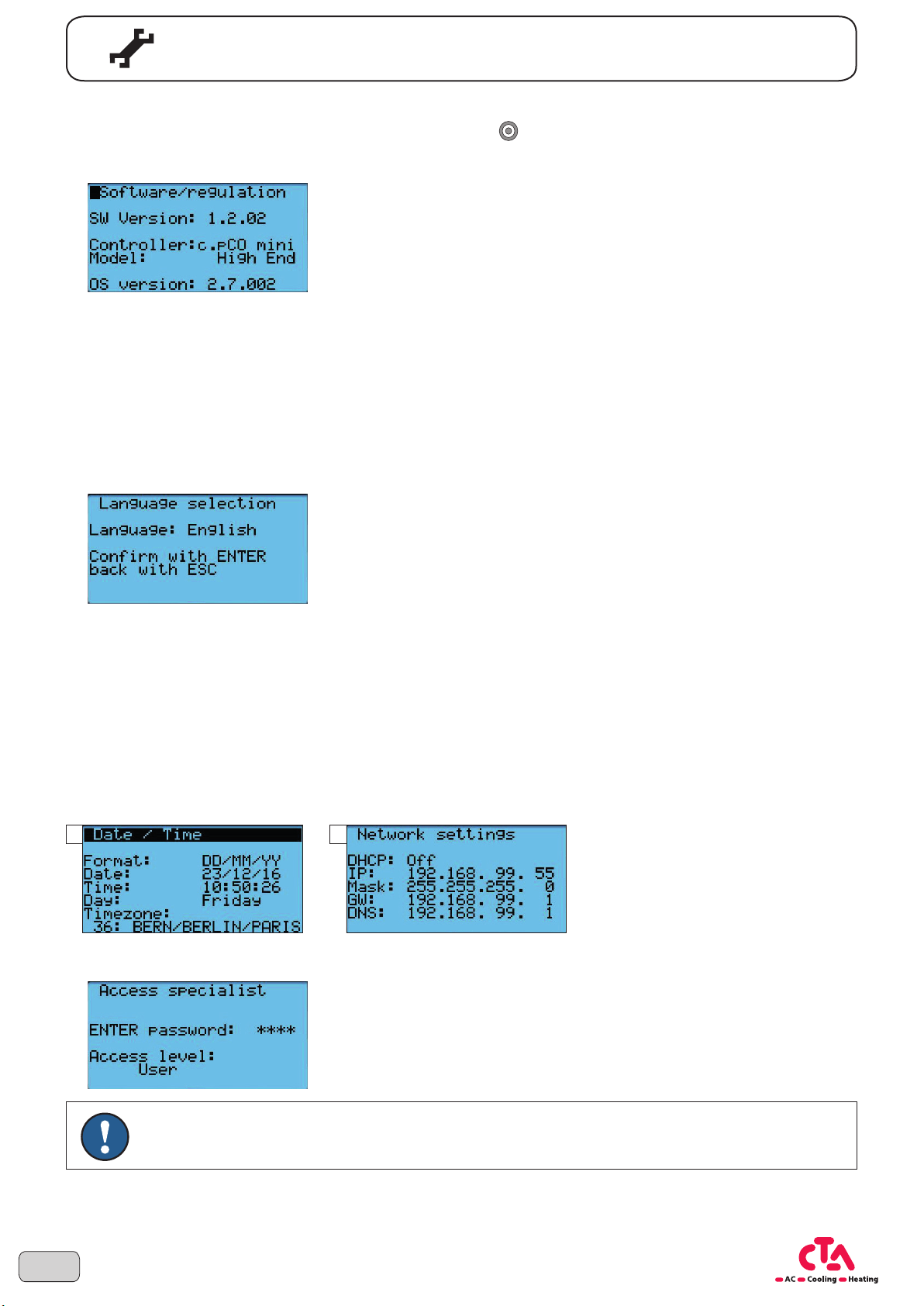
The following settings can be adapted using the program key (keep pressed for 3 seconds).
3.8.1 Software / regulation
Versions of the software or operating system stored on the controller can be called up here. Where required, these
can be provided to customer services.
3.8.2 Languages
The following languages are available.
• German
• English
• French
3.8.3 Time, date and network information
The controller has an annual clock that contains the time, the weekday and the date. To guarantee the function of
the heating program, the time and the date must be set correctly. The next pages contains information about the
network settings.
• Format date
• Date
• Time
• Time zone
1 2
3.8.4 Service level
26
NOTE Passwords are only made available to specialist personnel on request.
Subject to technical changes © CTA 10/2016 www.cta.ch
Page 27
A
4 Index
Alarms ..............................................................................................................................................................
Automatic mode .........................................................................................................................................
10, 25
13, 14, 17
C
Care of the unit .........................................................................................................................................................
Classification of risks ................................................................................................................................................
Comfort phase ...........................................................................................................................................
Commissioning .......................................................................................................................................................
Control unit and keys ..............................................................................................................................................
Cooling mode .........................................................................................................................................................
Copyright .................................................................................................................................................................
Customer service .....................................................................................................................................................
14, 18, 21
D
Date .....................................................................................................................................................
Disclaimer .................................................................................................................................................................
Disinfection. see alsolegionella program
Disposal .............................................................................................................................................................
10, 11, 19, 26
9, 11
E
Emergency operation .................................................................................................................................
Error messages ......................................................................................................................................................
External blocked .....................................................................................................................................................
10, 14, 19
9
6
25
10
21
4
8
4
25
12
F
Flow .......................................................................................................................................................................
Frost protection setpoint ...................................................................................................................................
13, 14
G
Guarantee ................................................................................................................................................................
Guarantee terms .......................................................................................................................................................
H
Heating circuit ..................................................................................................................................................
Heating limit ............................................................................................................................................................
Hysteresis ...............................................................................................................................................................
13, 14
I
Intended purpose .....................................................................................................................................................
L
Languages .............................................................................................................................................................
Legionella program ...........................................................................................................................................
Legionella temperature .....................................................................................................................................
18, 20
18, 19
M
24
8
8
17
20
8
26
Maintenance of the unit ............................................................................................................................................
N
Navigation bar ........................................................................................................................................................
Nominal setpoint ..............................................................................................................................................
18, 19
9
11
27Subject to technical changes © CTA 10/2016 www.cta.ch
Page 28

O
Index
Operating modes ..............................................................................................................................................
Operation .................................................................................................................................................................
13, 21
P
Password entry ......................................................................................................................................................
Protective mode .........................................................................................................................................
13, 14, 17
R
Re-charge hysteresis ..............................................................................................................................................
Reduced mode .................................................................................................................................................
Reduced value .......................................................................................................................................................
13, 20
S
Safety ...................................................................................................................................................................
Setpoint ................................................................................................................................................
Settings ......................................................................................................................................................
Slope characteristic curve .......................................................................................................................................
Software .................................................................................................................................................................
Status display .........................................................................................................................................................
Summer / Winter time switchover ...........................................................................................................................
Symbols used .......................................................................................................................................................
10, 14, 20, 22
6, 7
11, 25, 26
6, 7
T
8
10
20
14
15
26
11
17
Time ...............................................................................................................................................
10, 11, 12, 20, 26
W
Warranty ...................................................................................................................................................................
8
28
Subject to technical changes © CTA 10/2016 www.cta.ch
Page 29
Subject to technical changes © CTA 10/2016 www.cta.ch
Notes
29
Page 30
Notes
30
Subject to technical changes © CTA 10/2016 www.cta.ch
Page 31
Subject to technical changes © CTA 10/2016 www.cta.ch
Notes
31
Page 32

Bern CTA AG
Hunzikenstrasse 2
CH-3110 Münsingen
www.cta.ch
10/16 Item no. D3215 Subject to technical changes
 Loading...