

Page 1

Technical Reference
12-Slot Passive Backplanes
1641 McGaw Avenue
Irvine, California 92614
P/N PB-12-SLOT-DOC Revision 1, November 1997
Page 2

Page 3

Features
1 Single Board Computer (SBC) connector for easy
®
upgrades through the latest Pentium
and Pentium® Pro
products. The SBC is compatible with any CSS Single
Board Computer
Basic connectors provided for speakers, hard disk LED,
reset/turbo LED, keylock, PS/2 mouse and CMOS
battery
Power connectors for both 5 volt and 3 volt power source
Auxiliary power connectors for flexibility in backplane-
to-chassis mounting
PB-12 Slot
iii
Page 4

FCC Standards
The FCC (Federal Communications Commission) restricts
the amount of radiation and radio frequency emissions
coming from computing equipment.
Note: This equipment has been tested and found to comply
with the limits for a Class B digital device
pursuant to Part 15 of the FCC Rules. These limits
are designed to provide reasonable protection against harmful
interference in a residential installation. This equipment
generates, uses, and can radiate radio frequency energy and,
if not installed and used in accordance with the instructions,
may cause harmful interference to radio communications.
However, there is no guarantee that interference will not
occur in a particular installation. If this equipment does cause
harmful interference to radio or television reception, which
can be determined by turning the equipment off and on, the
use is encouraged to try to correct the interference by one
or more of the following measures:
Reorient or relocate the receiving antenna.
Increase the separation between the equipment and
receiver.
Connect the equipment into an outlet on a circuit
different from that to which the receiver is connected.
Consult the dealer or an experienced radio/TV technician
for help.
CSS Labs is not responsible for any radio or television
interference caused by unauthorized modifications to this
equipment. Operation with non-certified peripherals is likely
to result in interference to radio and TV reception.
iv PB-12 Slot
Page 5

To ensure compliance to FCC non-interference regulations,
peripherals attached to this device require shielded I/O cables.
NOTICE: The use of a non-shielded I/O cable with this
device is in violation of U.S. Federal law and will not allow
the device to meet the maximum emission limits.
CAUTION: Any changes or modifications not expressly
approved by the grantee of this device could void the users
authority to operate the equipment.
Note: If you have purchased the miniature tower system,
please note the following...
WARNING: The system is to be installed on desk or table
tops only. The unit will become unstable if operated as a floor
standing unit and unintentional force is applied to the top of
the unit.
Turn the unit off and unplug the power cord before you
open the cover to install any cards or peripheral devices.
PB-12 Slot
v
Page 6

WARNING
CAUTION: THERE IS A DANGER OF EXPLOSION IF
THE BATTERY IS INCORRECTLY REPLACED.
REPLACE ONLY WITH THE SAME OR EQUIVALENT
TYPE RECOMMENDED BY THE MANUFACTURER.
DISCARD USED BATTERIES ACCORDING TO THE
MANUFACTURERS INSTRUCTIONS.
ATTENTION: IL Y A DANGER DEXPLOSION SIL Y A
REMPLACEMENT INCORRECT DE LA BATTERRIE.
REMPLACER UNIQUEMENT AVEC UNE BATTERI DU
MEME TYPE OU DUN TYPE RECOMMENDE PAR LE
CONSTRUCTEUR. ETTERAU REBUT LES
BATTERRIES USAGEES CONFORMEMANT AUX
INSTRUCTIONS DU FABRICATANT.
vi PB-12 Slot
Page 7

NOTICE
The information within this manual is subject to change
without notice.
CSS Laboratories, Incorporated shall not be held liable for
technical or editorial errors or omissions contained in herein;
nor for incidental or consequential damages resulting from the
furnishing, performance or use of this material.
No part of this publication may be reproduced, stored in a
retrieval system, or transmitted, in any form or by any means,
mechanical, photocopying, recording or otherwise, without
the prior written permission of CSS Laboratories, Inc.
Product names mentioned herein are for identification
purposes only, and may be trademarks and/or registered
trademarks of their respective companies.
© 1997 CSS Laboratories, Inc. All rights reserved.
P/N PB-12-SLOT-DOC Revision 1 November, 1997
PB-12 Slot
vii
Page 8

Table of Contents
Section 1 - Introduction
Document Overview........................................................... 1-1
Basic Features .................................................................... 1-1
Connectors ......................................................................... 1-2
Single Board Computer Bus .............................................. 1-2
PCI Bus Bridge .................................................................. 1-2
PCI Bus Shared Interrupts ................................................. 1-4
Section 2 - The Connectors
Overview ............................................................................ 2-1
Basic Features .................................................................... 2-1
Connectors ......................................................................... 2-2
5 Volt Power Connector; Auxiliary Connector .................. 2-2
3 Volt Power Supply Connector; Auxiliary Connector ...... 2-3
Keyboard Connector .......................................................... 2-3
Speaker Connector ............................................................. 2-3
PS/2 Mouse Connector ...................................................... 2-4
Hard Drive LED ................................................................ 2-4
Reset/Turbo Connector ...................................................... 2-5
Front Panel Connector ....................................................... 2-5
Infrared Connector ............................................................. 2-5
Power LED/Keylock .......................................................... 2-6
Battery Connector .............................................................. 2-6
viii PB-12 Slot
Page 9

Section 3 - PB-10309
Features .............................................................................. 3-1
PCI Slots ............................................................................ 3-1
Single Board Computer Bus Slot ....................................... 3-1
Power Connectors .............................................................. 3-1
PCI Bus Shared Interrupts ................................................. 3-2
Terminating Resistors ........................................................ 3-2
Connectors ......................................................................... 3-3
Section 4 - PB-10606
Features .............................................................................. 4-1
PCI Slots ............................................................................ 4-1
Single Board Computer Bus Slot ....................................... 4-1
Power Connectors .............................................................. 4-1
PCI Bus Shared Interrupts ................................................. 4-2
Terminating Resistors ........................................................ 4-2
Connectors ......................................................................... 4-3
Section 5 - PB-10804
Features .............................................................................. 5-1
PCI Slots ............................................................................ 5-1
Single Board Computer Bus Slot ....................................... 5-1
Power Connectors .............................................................. 5-1
Terminating Resistors ........................................................ 5-2
Connectors ......................................................................... 5-3
PB-12 Slot
ix
Page 10

Page 11

Section 1 - Introduction
Document Overview
This document describes the technical features of CSS 12-slot
passive backplanes. The topics include:
Connectors - description of connectors and their
functions
Illustrations - illustrations of each 12-slot passive
backplane
Jumpers - descriptions and pin assignments of all 12-slot
passive backplane jumpers (where ever applicable)
This document is divided into several sections. Section two
describes backplane connectors in detail. Sections three
through six provide backplane illustrations and board-specific
feature descriptions. These sections also provide jumper
descriptions for boards designed with jumpers.
Basic Features
CSS passive backplanes provide a number of ISA and PCI
bus slots. Bus configurations are discussed in sections of this
document devoted to specific boards.
Introduction
1-1
Page 12

Connectors
Hard disk activity indicator LED connectors are provided for
either an add-in or single board computer (SBC) on-board
controller. Front panel, reset/turbo, mouse, speaker and
keylock connectors are also provided.
5 volt and 3.3 volt power connectors on the board supply
power to the ISA and PCI busses, add-in boards and SBC.
Auxiliary sets are provided in alternate locations.
Also provided is a connector for infrared-based peripheral
devices. The connector attaches to an add-in transceiver.
Single Board Computer Bus
To facilitate CSS SBCs, the backplanes use a basic ISA bus
architecture with a PCI bus extension. CSS backplanes
accept all CSS single board computers.
PCI Bus Bridge
PCI bus architecture design imposes a four PCI bus limit per
system. CSSs passive backplanes expand beyond this
limitation by incorporating a PCI bridge onto the board.
On CSS passive backplanes with more than four PCI busses,
the first two PCI busses communicate directly with the
associated SBC. These two PCI busses operate at PCI level
0.
All subsequent PCI busses communicate with the SBC
through the PCI bridge. These PCI busses operate at PCI
level 1.
The following diagrams illustrate bus arrangements for six
PCI slot and nine PCI slot passive backplanes:
1-2
Introduction
Page 13
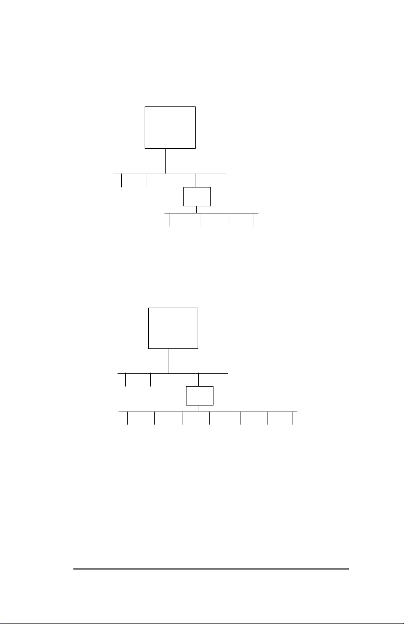
Single Board
Computer
PCI Level 0
PCI 1 PCI 2
PCI 3 PCI 4 PCI 5 PCI 6
PCI
Bridge
PCI Level 1
Figure 1-1: Six PCI Bus Passive Backplanes
Single Board
Computer
PCI Level 0
PCI 1 PCI 2
PCI 3 PCI 4 PCI 5 PCI 9
PCI
Bridge
PCI 6 PCI 7 PCI 8
PCI Level 1
Figure 1-2: Nine PCI Bus Passive Backplanes
Introduction
1-3
Page 14
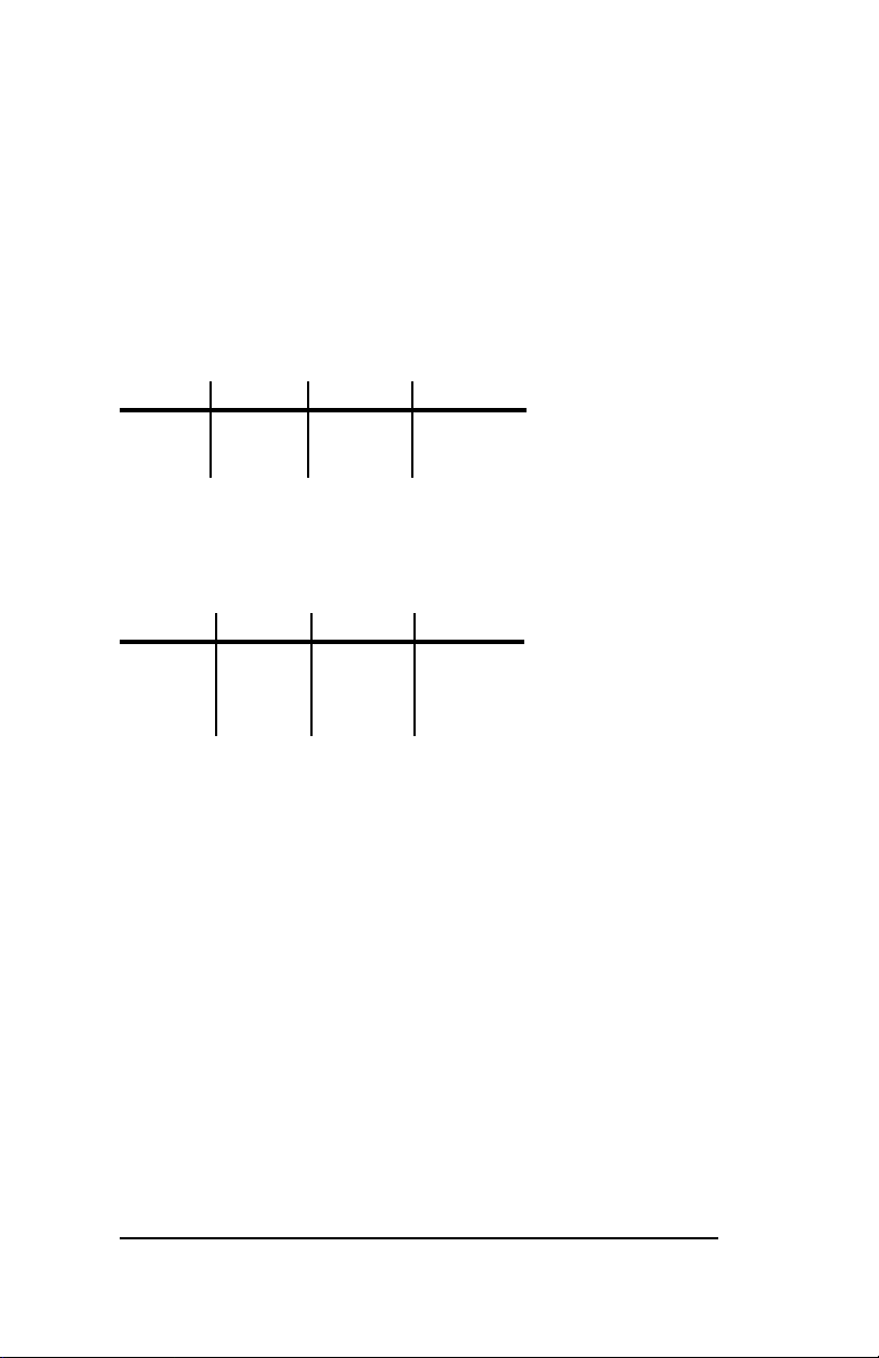
PCI Bus Shared Interrupts
Because of the PCI bus design limitation, passive backplanes
with more than four PCI busses are required to share some
interrupts. The following information outlines the shared
interrupt arrangement.
Six PCI Backplane
AB C D
PCI 4 PCI 1 PCI 2 PCI 3
PCI 5 PCI 6
Nine PCI Backplane
AB C D
PCI 4 PCI 1 PCI 2 PCI 3
PCI 8 PCI 5 PCI 6 PCI 7
PCI 9
1-4
Introduction
Page 15

Section 2 - The Connectors
Overview
This section describes the connectors and their functions.
These descriptions apply to all CSS 12-slot passive
backplanes.
Basic Features
Hard disk activity indicator LED connectors are provided for
either an add-in or SBC on-board controller. Front panel,
reset/turbo, mouse, speaker and keylock connectors are also
provided.
5 volt and 3 volt power connectors on the board supply power
to both the ISA and PCI busses, add-in boards and SBC.
Auxiliary sets are available in alternate
locations.
Connectors
2-1
Page 16
Connectors
All CSS Laboratories 12-slot passive backplane
provide the following connectors:
5 volt power
3 volt power
Auxiliary 5 volt
Auxiliary 3 volt
Keyboard
PS/2 Mouse
Speaker
Hard drive LED
Reset/Turbo LED
Front Panel
Infrared
Keylock
Battery
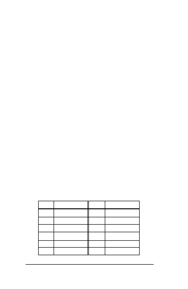
5 Volt Power Connector; Auxiliary Connector
The connectors attach the board to the power via the 5 volt
regulator. Orient the plugs black wires to sit side-by-side.
Pin Assignment Pin Assignment
1 Power good 7 Ground
2 +5Vdc 8 Ground
3 +12 Vdc 9 -5 Vdc
4 -12 Vdc 10 +5 Vdc
5 Ground 11 +5 Vdc
6 Ground 12 +5 Vdc
2-2
Connectors
Page 17
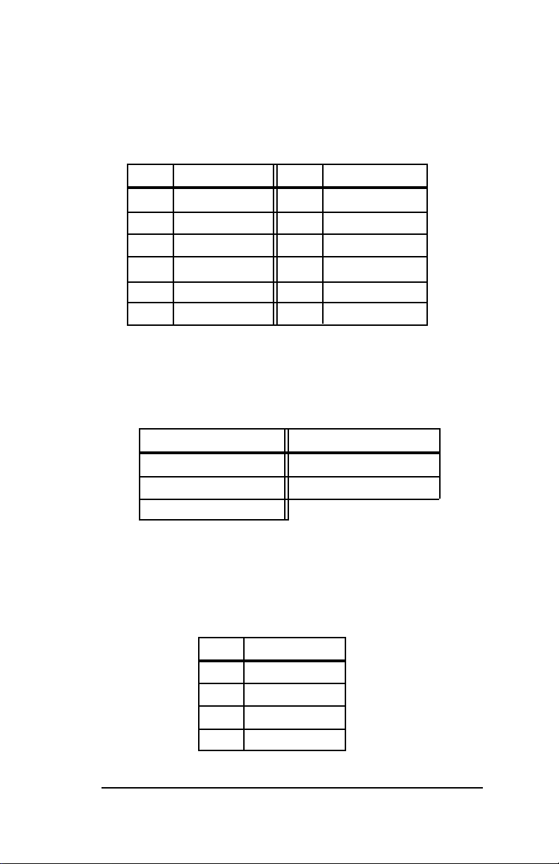
3 Volt Power Supply Connector; Auxiliary Connector
The connectors attach the board to the power via the 3 volt
regulator. Orient the plugs black wires to sit side-by-side.
Pin Assignment Pin Assignment
1 Ground 7 +3.3 Vdc
2 Ground 8 +3.3 Vdc
3 Ground 9 +3.3 Vdc
4 3.3 Vdc 10 Ground
5 3.3 Vdc 11 Ground
6 +3.3 Vdc 12 Ground
Keyboard Connector
Keyboard plugs are keyed for proper installation.
Pin Assignment Pin Assignment
1 Clock 4 Ground
2 Data 5 +5 Vdc
3 Not used
Speaker Connector
The speaker connector attaches to a standard chassis
speaker.
Pin Assignment
1 Speaker (-)
2 Not Used
3 Ground
4 Speaker (+)
Connectors
2-3
Page 18
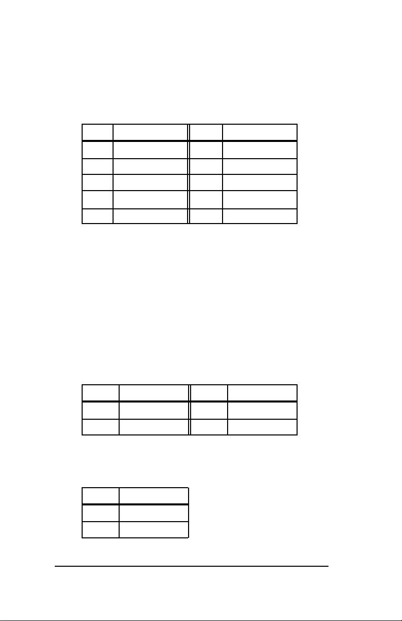
PS/2 Mouse Connector
The connector provides IBM PS/2 mouse support, leaving the
serial port open for options. Pin 1 is marked.
Pin Assignment Pin Assignment
1 Clock 6 Vcc
2 Not used 7 Ground
3 Not used 8 Data
4 Not used 9 Ground
5 Not used 10 Not Used
Hard Drive LED
These connectors attach hard drive access LEDs to the front
panel for either the on-board SBC controller or add-in
controller board, respectively. The LED lights when the drive
is accessed.
On-Board SBC IDE LED
Pin Assignment Pin Assignment
1 HD LED 3 HD LED
2 Power 4 Power
Add-In Board IDE LED
Pin Assignment
1 HD LED
2 Power
2-4
Connectors
Page 19
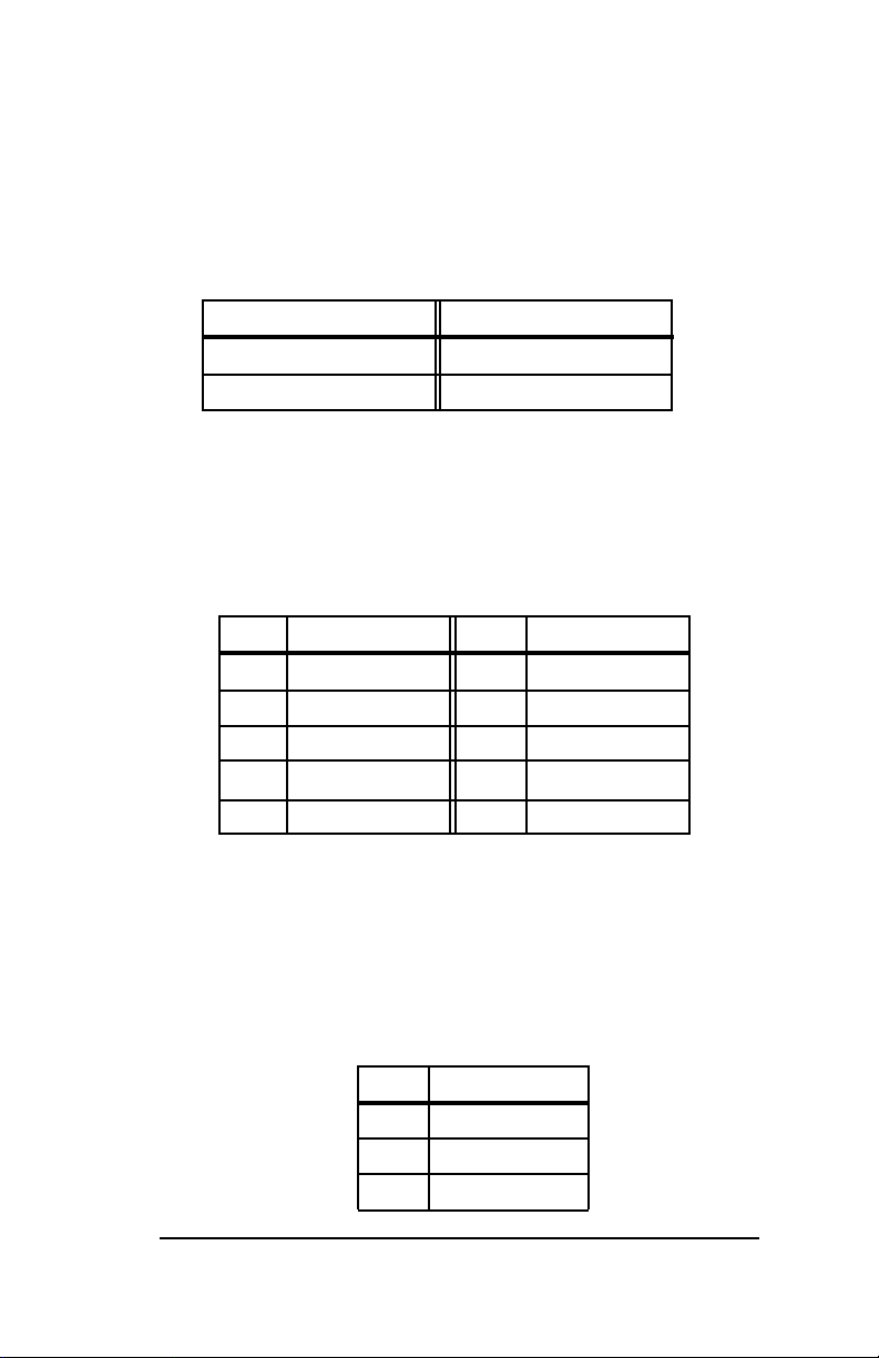
Reset/Turbo Connector
The reset button lets you perform a warm boot without
turning the system off. The turbo LED indicates the system is
running at the higher clock speed when it lights.
Pin Assignment Pin Assignment
1 Reset 3 Turbo LED
2 Ground 4 Ground
Front Panel Connector
This 10-pin connector is the interface between the system
board and the control panel on the front of the system case.
Pin Assignment Pin Assignment
1 Ground 6 Ground
2 Power LED 7 LED on
3 HD LED 8 Keylock
4 Not used 9 Power LED
5 Power LED 10 Reset
Infrared Connector
This connector attaches to an optional infrared add-in
controller. Infrared controllers can act as ports for a number
of peripheral devices including mouse, printer and keyboard.
Pin Assignment
1 Receiving
2 Ground
3 Transmitting
Connectors
2-5
Page 20
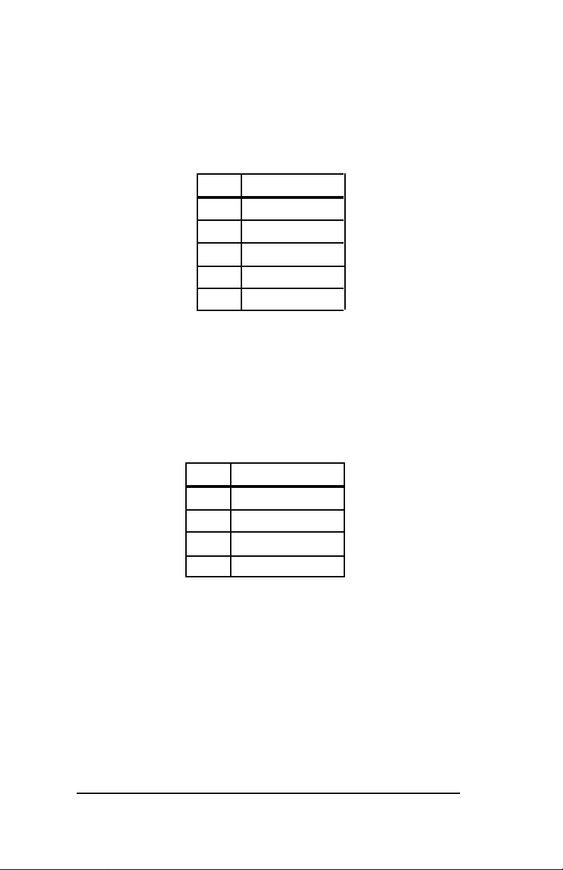
Power LED/Keylock
The power LED lights while the system is powered up. The
keylock disables the keyboard.
Pin Assignment
1 Power LED
2 Not used
3 Ground
4 Keylock
5 Ground
Battery Connector
The connector attaches the 3.3 volt lithium battery to the
board. The battery provides constant power to the single
board computers CMOS and has a typical life-span of five
years.
Pin Assignment
1 Battery Power
2 Not Used
3 Not used
4 Ground
2-6
Connectors
Page 21

Section 3 - PB-10309
Features
The four-layer PB-10309 provides three ISA expansion bus
slots and nine PCI expansion bus slots. Built in logic
bypasses the traditional four-slot PCI bus limitation, allowing
you to configure the backplane with up to nine PCI expansion
boards that can be used at the same time.
PCI Slots
PCI slots one through two communicate directly with the
single board computer. PCI slots three through nine utilize an
on-board chip to pass communications to the single board
computer. Please read Section 1, PCI Bus Bridge, for a more
thorough description.
Single Board Computer Bus Slot
The SBC slot is a combination of one EISA-style connector
and one PCI-style connector. The slot is proprietary and can
be configured with any CSS single board computer.
Power Connectors
The PB-10309 provides a 3.3 volt power connector and a 5
volt power connector. The board also provides two sets of
auxiliary 3.3 volt and 5 volt power connectors.
PB-10309
3-1
Page 22
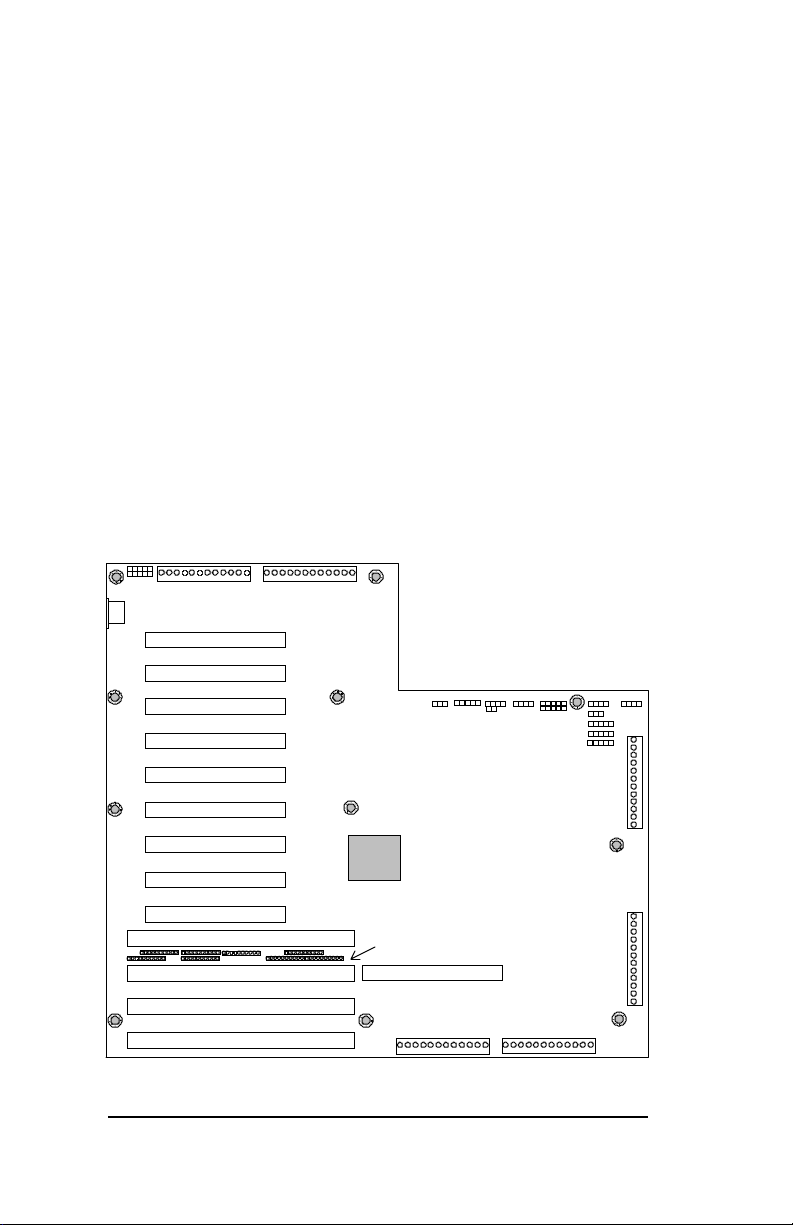
PCI Bus Shared Interrupts
Due to design limitations on PCI busses, the following slots
share interrupts: PCI 4/PCI 8; PCI 1/PCI 5/PCI 9;
PCI 2/PCI 6; PCI 3/PCI7. Boards configured on these busses
are capable of sharing interrupts.
Please read Section 1, PCI Bus Shared Interrupts, for a more
thorough explanation.
Terminating Resistors
A row of terminating resistors placed between bus slots
prevent bus signal reflections and interference.
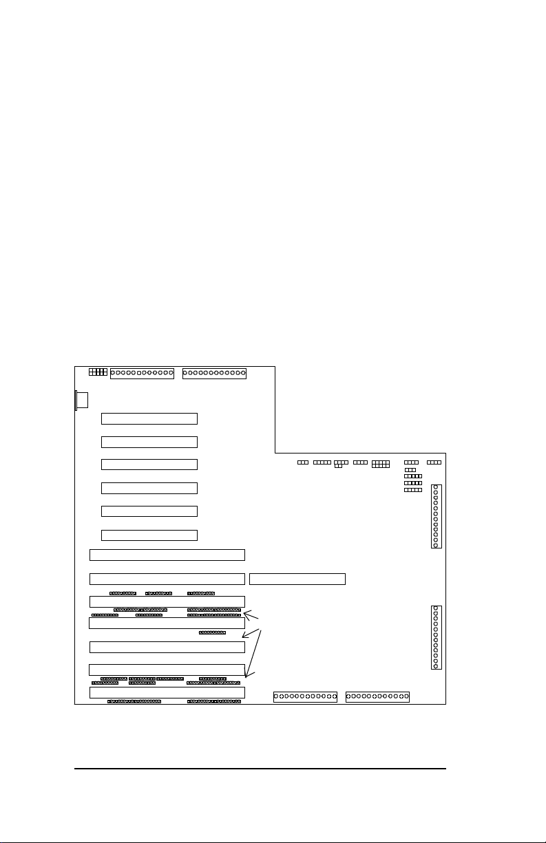
Mouse
1
11
KBRD
CON
JP31
CN1
P89
J150
J149
J148
J130
J128
J129
J127
5V Power
Connector
PCI 9
PCI 8
PCI 7
PCI 6
PCI 5
PCI 4
PCI 3
P90
3V Power
Connector
J120
J113 J108 J111 JP30 J112 J109
1
1 11
1 1
1
JP29
Infrared
HD LED
Keylock
Front Panel
Rst/Turbo LED
1
1
1
J132
1
J131
1
Auxiliary
5V Power
Connector
3.3V Lit h.
J133
J134
Speaker
3-2
J123
J122
J20
J33
J30
PCI 2
PCI 1
ISA
EISA
ISA
ISA
CPU SLOT
TERMINATING
RESISTORS
J121
P91 P92
Figure 3-1: PB-10309 Passive Backplane
Auxiliary Power Connectors
5V 3V
Auxiliary
3V Powe r
Connector
11
PB-10309
1
Page 23
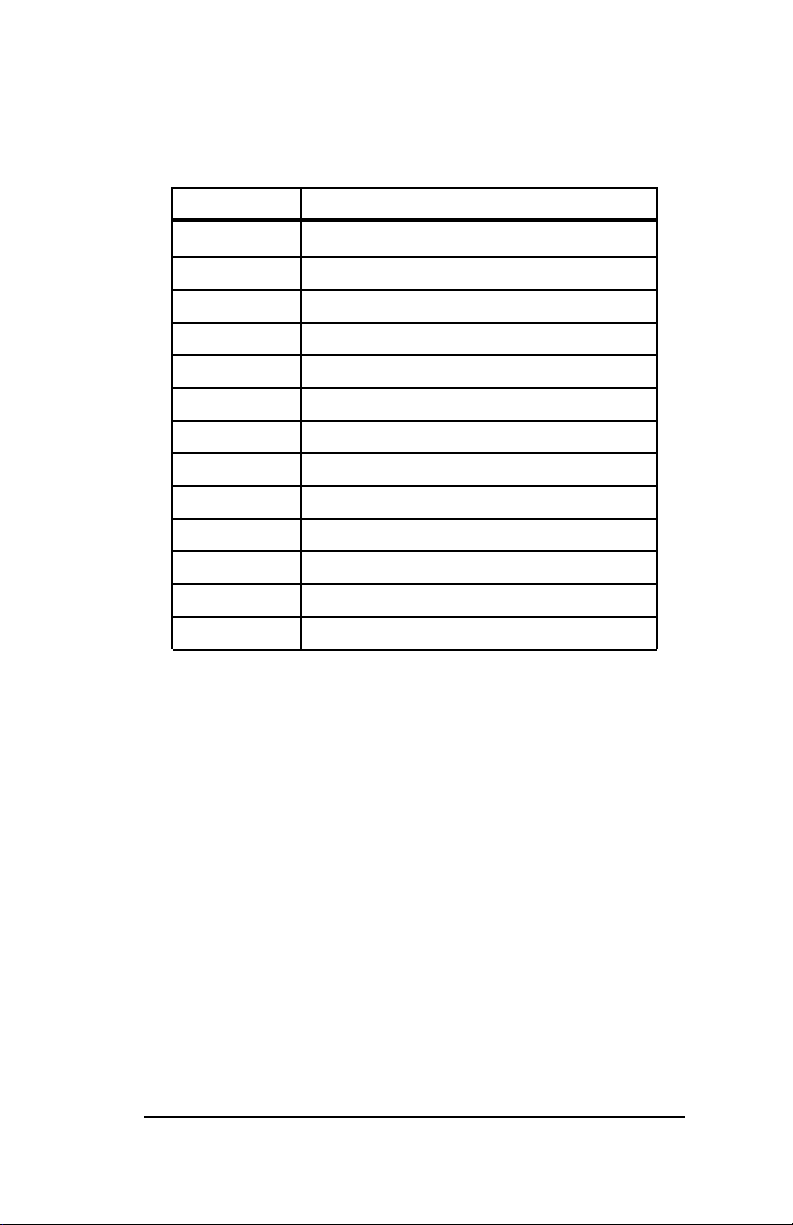
Connectors
Connector Description
P89 5 volt power
P90 3.3 volt power connector
P91 Auxiliary 5 volt connectors
P92 Auxiliary 3.3 volt connectors
CN1 Keyboard connector
JP31 PS/2 Mouse connector
J109 Speaker
J108, JP29 IDE hard drive LEDs
J111 Reset/Turbo LED
JP30 Front Panel connector
J120 Infrared connector
J113 Power LED/Keylock
J112 Battery connector
PB-10309
3-3
Page 24

3-4
PB-10309
Page 25

Section 4 - PB-10606
Features
The four-layer PB-10606 provides six ISA expansion bus
slots and six PCI expansion bus slots. Built in logic bypasses
the traditional four-slot PCI bus limitation, allowing you to
configure the backplane with up to six PCI expansion boards
that can be used at the same time.
PCI Slots
PCI slots one through two communicate directly with the
single board computer. PCI slots three through six utilize an
on-board chip to pass communications to the single board
computer. Please read Section 1, PCI Bus Bridge, for a more
thorough description.
Single Board Computer Bus Slot
The SBC slot is a combination of one EISA-style connector
and one PCI-style connector. The slot is proprietary and can
be configured with any CSS single board computer.
Power Connectors
The PB-10606 provides a 3.3 volt power connector and a 5
volt power connector. The board also provides two sets of
auxiliary 3.3 volt and 5 volt power connectors.
PB-10606
4-1
Page 26
PCI Bus Shared Interrupts
Due to design limitations on PCI busses, the following slots
share interrupts: PCI 1/PCI 5; PCI 2/PCI 6. Boards
configured on these busses be capable of sharing interrupts.
Please read Section 1, PCI Bus Shared Interrupts, for a more
thorough explanation.
Terminating Resistors
Five rows of terminating resistors placed between bus slots
prevent bus signal reflections and interference.
Mouse
1
11
CN1
KBRD
CON
JP31
5V Power
P89 P90
Connector
PCI 6
J130
PCI 5
J128
PCI 4
J129
PCI 3
J127
PCI 2
J123
PCI 1
J122
ISA
J146
3.3V Power
Connector
Front Panel
1
1
1
J132
1
J131
1
Auxiliary
5V Power
Connector
3.3V Li th.
J133
J134
J120 J113 J108 J111 JP30 J112 J109
1 11
1 1
1
1
JP29
Infrared
Keylock
HD LED
Rst/Turbo LED
Speaker
1
4-2
U103
J126
J124
J20
J33
J30
EISA
ISA
ISA
ISA
ISA
ISA
CPU SLOT
J121
TERMINATING
RESISTORS
P91
5V
Figure 5-1: The PB-10606
Auxiliary Power Connectors
3.3V
Auxiliary
3.3V Pow er
Connector
P92
11
PB-10606
1
Page 27
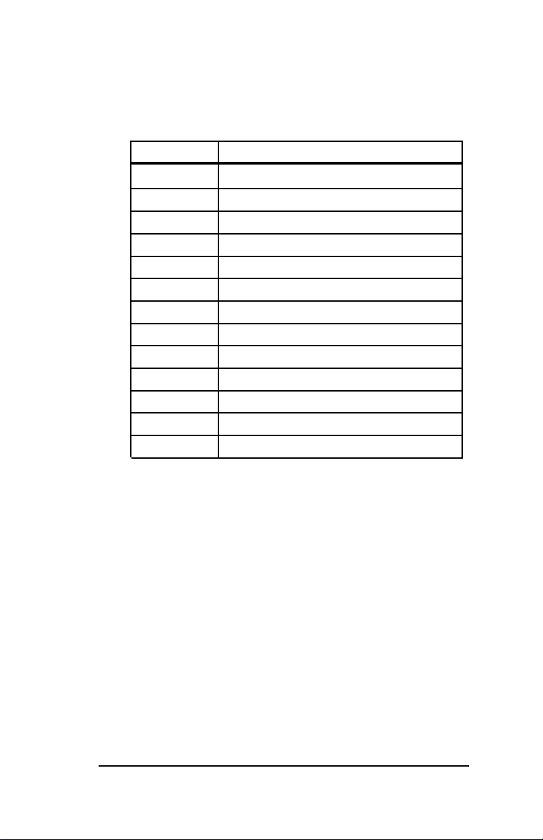
Connectors
Connector Description
P89 5 volt power
P90 3.3 volt power connector
P91 Auxiliary 5 volt connectors
P92 Auxiliary 3.3 volt connectors
CN1 Keyboard connector
JP31 PS/2 Mouse connector
J109 Speaker
J108, JP29 IDE hard drive LEDs
J111 Reset/Turbo LED
JP30 Front Panel connector
J120 Infrared connector
J113 Power LED/Keylock
J112 Battery connector
PB-10606
4-3
Page 28

4-4
PB-10606
Page 29

Section 5 - PB-10804
Features
The four-layer PB-10804 provides three ISA expansion bus
slots and nine PCI expansion bus slots. Built in logic
bypasses the traditional four-slot PCI bus limitation, allowing
you to configure the backplane with up to nine PCI expansion
boards that can be used at the same time.
PCI Slots
PCI slots one through four communicate directly with the
single board computer. All four PCI busses can be
concurrently configured with PCI boards.
Single Board Computer Bus Slot
The SBC slot is a combination of one EISA-style connector
and one PCI-style connector. The slot is proprietary and can
be configured with any CSS single board computer.
Power Connectors
The PB-10804 provides a 3.3 volt power connector and a 5
volt power connector. The board also provides two sets of
auxiliary 3.3 volt and 5 volt power connectors.
PB-10804
5-1
Page 30
Terminating Resistors
A row of terminating resistors placed between bus slots
prevent bus signal reflections and interference.
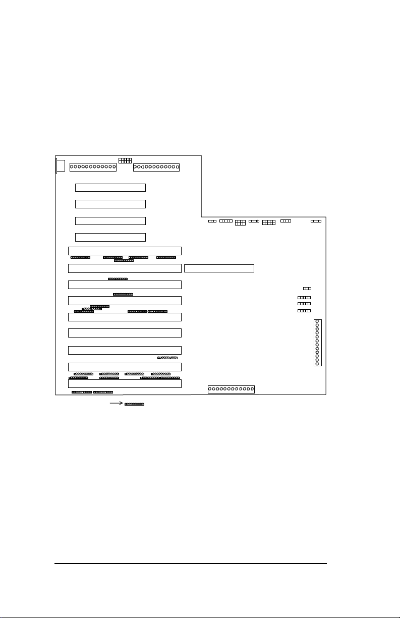
Mo use
U89
PCI 4
PCI 3J146
PCI 2
PCI 1
ISA
EIS A
ISA
ISA
ISA
ISA
ISA
ISA
ISA
JP31
1
3.3V Power Connector
1
CPU SLOT
U117
J114
HD LED
Rst/Turbo LED
Keylock
Infrare d
J120
J113 J108 J111 JP30 J112 J109
1
1
JP29
U115
Auxiliary 5V Power
Front Panel
1 1
1
1
1
1
3.3V Lit h.
1
J130
J129
J128
J131
5V Power
5V Power Connector
1
CN1
KBRD
CON
J146
J145
J147
J144
U88
J143
J142
J140
J125
J20
J33
J30
Terminat ing Resistor
U118
Auxiliary
Speaker
1
1
1
1
1
5-2
Figure 6-1: The PB-10804
PB-10804
Page 31
Connectors
Connector Description
P89 5 volt power
P90 3.3 volt power connector
P115 Auxiliary 5 volt connectors
P116 Auxiliary 3.3 volt connectors
CN1 Keyboard connector
JP31 PS/2 Mouse connector
J109 Speaker
J108, JP29 IDE hard drive LEDs
J111 Reset/Turbo LED
JP30 Front Panel connector
J120 Infrared connector
J113 Keylock
J112 Battery connector
PB-10804
5-3
Page 32

5-4
PB-10804
 Loading...