

Product Numbers
BAR-HA1632-TW-125-XX
BAR-HA1833-TW-125-XX
BAR-HA3638-TW-125-XX
BAR-HA2424-TW-125-XX
BAR-HA2736-TW-125-XX
BAR-HA2040-TW-125-XX
BAR-HA2448-TW-125-XX
BAR-HA3030-TW-125-XX
BAR-HA3636-TW-125-XX
Horizontal Angled Grab Bar
- Material: 304 stainless steel
- Available Finishes: Oil rubbed bronze (OB)
Satin Stainless (SA)
Satin Peened (PN)
Polished Chrome (PO)
Matte Black (MB)
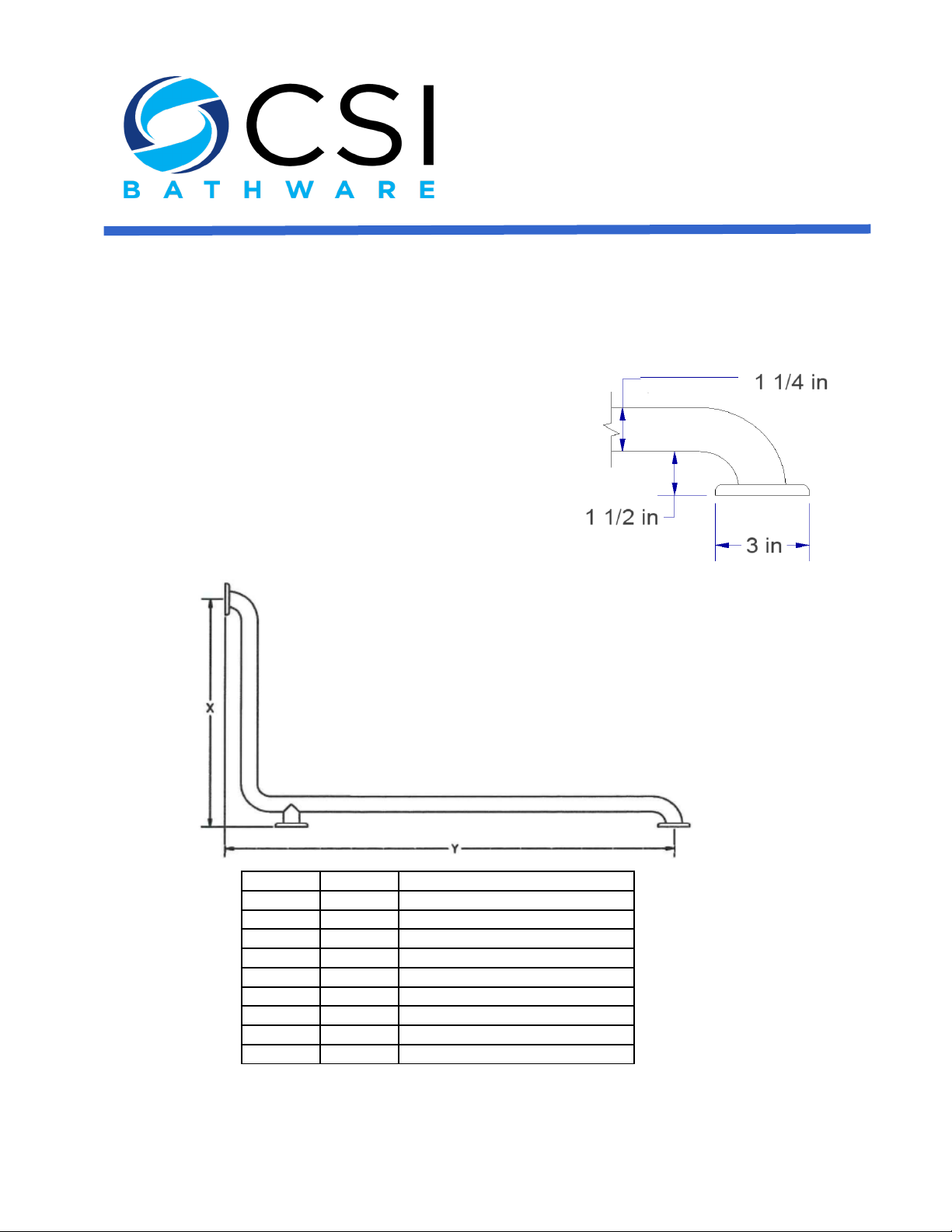
- Dimensions:
- Length (flange center to center): table below
- Tube outside diameter: 1.25"
- Tube wall: 18 gauge (1.2 mm)
- Flange cover: 14 gauge, cover rotates into locked
position to conceals flange mount plate and screws
- ADA Compliant
1301 Westinghouse Blvd, Suite I
Charlotte, NC 28273
Phone: 704-843-9292
Fax: 704-943-0675
support@csibathware.com
www.csibathware.com
X Length Y Length
16" 32"
18" 33"
24" 24"
27" 36"
20" 40"
24" 48"
30" 30"
36" 36"
36" 38"

IMPORTANT INSTRUCTIONS
SAFETY NOTE: Concealed In-Wall support backing is ALWAYS REQUIRED for this product (not included)
– and must be supplied and selected by a licensed installer/contractor to meet both weight bearing and
local code requirements. PRODUCT INSTALLATION SHOULD BE DONE BY A LICENSED
INSTALLER/CONTRACTOR.
CAUTION: Personal injury and/or property damage may result from improper wall support or mounting,
which is not covered under warranty.
WARNING: Do NOT use this instruction sheet for grab bars with welded stud or internal threads.
IT IS ESSENTIAL TO MARK THE CENTERLINE DISTANCE BETWEEN THE TWO MOUNTING FLANGE PLATES
ON EACH SIDE AS WELL AS THE DISTANCE FROM CENTER OF EACH MOUNTING PLATE TO THE FINISH
FLOOR TO ASSURE PROPER ALIGNMENT.
Installation Notes:
1. Bar as Selected
2. Flange Cover Plate
3. Flange
4. Wood Stud
5. Drywall
6. Tile (if applicable)
7. 1/4” (6mm) Diameter Pilot Hole –TILE PROJE CT S ONLY
8. 1/8” (3mm) Diameter Pilot Hole into Wood Stud
9. 10/24” x 2” Threaded Stainless Steel Hanger Bolt
10. Threaded Stainless Steel Bolt Nut
11. 2” Self-tapping screw
Installation Steps:
1. Locate wall stud or previously installed backer board.
2. Use the flange as a template to mark the mounting hole locations. (We rec ommend using a level to
achieve perfect horizontal or vertical mounting.)
3. Drill 1/8” (3mm) diameter pil ot hole into wood stud for each flange.
a. If wall is tiled, drill through the tile with a 1/4” (6mm) diameter masonry drill bit.
4. Drive hanger bolts for center post directly into wood stud using hanger bolt driver leaving 1/4” of
thread exposed. (NOTE: Hanger bolts for center post MUST be installed before the end posts are
fastened to the wall.)
5. Place Flange over exposed hanger bolts.
6. Screw bolt nut onto hanger bolts until secure.
7. Using the 2” self-tapping screws, fasten each end post to the wall.
8. After all flanges are secured, apply bead of clear sealant around bottom rim of flange cover plate
and carefully align the cover plate locking tabs with the slots in the flange.
9. Turn the flange cover plate 15 degrees clockwise to secure.
 Loading...