

Page 1
INSTRUCTION MANUAL
SR50A, SR50A-316SS,
Revision: 10/16
Copyright © 2007- 2016
Campbell Scientific, Inc.
Sonic Ranging Sensors
and SR50AH
Page 2

Page 3

Limited Warranty
“Products manufactured by CSI are warranted by CSI to be free from defects in
materials and workmanship under normal use and service for twelve months
from the date of shipment unless otherwise specified in the corresponding
product manual. (Product manuals are available for review online at
www.campbellsci.com.) Products not manufactured by CSI, but that are resold
by CSI, are warranted only to the limits extended by the original manufacturer.
Batteries, fine-wire thermocouples, desiccant, and other consumables have no
warranty. CSI’s obligation under this warranty is limited to repairing or
replacing (at CSI’s option) defective Products, which shall be the sole and
exclusive remedy under this warranty. The Customer assumes all costs of
removing, reinstalling, and shipping defective Products to CSI. CSI will return
such Products by surface carrier prepaid within the continental United States of
America. To all other locations, CSI will return such Products best way CIP
(port of entry) per Incoterms ® 2010. This warranty shall not apply to any
Products which have been subjected to modification, misuse, neglect, improper
service, accidents of nature, or shipping damage. This warranty is in lieu of all
other warranties, expressed or implied. The warranty for installation services
performed by CSI such as programming to customer specifications, electrical
connections to Products manufactured by CSI, and Product specific training, is
part of CSI's product warranty. CSI EXPRESSLY DISCLAIMS AND
EXCLUDES ANY IMPLIED WARRANTIES OF MERCHANTABILITY
OR FITNESS FOR A PARTICULAR PURPOSE. CSI hereby disclaims,
to the fullest extent allowed by applicable law, any and all warranties and
conditions with respect to the Products, whether express, implied or
statutory, other than those expressly provided herein.”
Page 4

Assistance
Products may not be returned without prior authorization. The following
contact information is for US and international customers residing in countries
served by Campbell Scientific, Inc. directly. Affiliate companies handle repairs
for customers within their territories. Please visit www.campbellsci.com to
determine which Campbell Scientific company serves your country.
To obtain a Returned Materials Authorization (RMA), contact CAMPBELL
SCIENTIFIC, INC., phone (435) 227-9000. Please write the issued RMA
number clearly on the outside of the shipping container. Campbell Scientific’s
shipping address is:
CAMPBELL SCIENTIFIC, INC.
RMA#_____
815 West 1800 North
Logan, Utah 84321-1784
For all returns, the customer must fill out a “Statement of Product Cleanliness
and Decontamination” form and comply with the requirements specified in it.
The form is available from our website at www.campbellsci.com/repair. A
completed form must be either emailed to [email protected] or faxed to
(435) 227-9106. Campbell Scientific is unable to process any returns until we
receive this form. If the form is not received within three days of product
receipt or is incomplete, the product will be returned to the customer at the
customer’s expense. Campbell Scientific reserves the right to refuse service on
products that were exposed to contaminants that may cause health or safety
concerns for our employees.
Page 5

Safety
DANGER — MANY HAZARDS ARE ASSOCIATED WITH INSTALLING, USING, MAINTAINING, AND WORKING ON OR AROUND
TRIPODS, TOWERS, AND ANY ATTACHMENTS TO TRIPODS AND TOWERS SUCH AS SENSORS, CROSSARMS, ENCLOSURES,
ANTENNAS, ETC. FAILURE TO PROPERLY AND COMPLETELY ASSEMBLE, INSTALL, OPERATE, USE, AND MAINTAIN TRIPODS,
TOWERS, AND ATTACHMENTS, AND FAILURE TO HEED WARNINGS, INCREASES THE RISK OF DEATH, ACCIDENT, SERIOUS
INJURY, PROPERTY DAMAGE, AND PRODUCT FAILURE. TAKE ALL REASONABLE PRECAUTIONS TO AVOID THESE HAZARDS.
CHECK WITH YOUR ORGANIZATION'S SAFETY COORDINATOR (OR POLICY) FOR PROCEDURES AND REQUIRED PROTECTIVE
EQUIPMENT PRIOR TO PERFORMING ANY WORK.
Use tripods, towers, and attachments to tripods and towers only for purposes for which they are designed. Do not exceed design limits.
Be familiar and comply with all instructions provided in product manuals. Manuals are available at www.campbellsci.com or by
telephoning (435) 227-9000 (USA). You are responsible for conformance with governing codes and regulations, including safety
regulations, and the integrity and location of structures or land to which towers, tripods, and any attachments are attached. Installation
sites should be evaluated and approved by a qualified engineer. If questions or concerns arise regarding installation, use, or
maintenance of tripods, towers, attachments, or electrical connections, consult with a licensed and qualified engineer or electrician.
General
• Prior to performing site or installation work, obtain required approvals and permits. Comply
with all governing structure-height regulations, such as those of the FAA in the USA.
• Use only qualified personnel for installation, use, and maintenance of tripods and towers, and
any attachments to tripods and towers. The use of licensed and qualified contractors is highly
recommended.
• Read all applicable instructions carefully and understand procedures thoroughly before
beginning work.
• Wear a hardhat and eye protection, and take other appropriate safety precautions while
working on or around tripods and towers.
• Do not climb tripods or towers at any time, and prohibit climbing by other persons. Take
reasonable precautions to secure tripod and tower sites from trespassers.
• Use only manufacturer recommended parts, materials, and tools.
Utility and Electrical
• You can be killed or sustain serious bodily injury if the tripod, tower, or attachments you are
installing, constructing, using, or maintaining, or a tool, stake, or anchor, come in contact with
overhead or underground utility lines.
• Maintain a distance of at least one-and-one-half times structure height, 20 feet, or the distance
required by applicable law, whichever is greater, between overhead utility lines and the
structure (tripod, tower, attachments, or tools).
• Prior to performing site or installation work, inform all utility companies and have all
underground utilities marked.
• Comply with all electrical codes. Electrical equipment and related grounding devices should be
installed by a licensed and qualified electrician.
Elevated Work and Weather
• Exercise extreme caution when performing elevated work.
• Use appropriate equipment and safety practices.
• During installation and maintenance, keep tower and tripod sites clear of un-trained or non-
essential personnel. Take precautions to prevent elevated tools and objects from dropping.
• Do not perform any work in inclement weather, including wind, rain, snow, lightning, etc.
Maintenance
• Periodically (at least yearly) check for wear and damage, including corrosion, stress cracks,
frayed cables, loose cable clamps, cable tightness, etc. and take necessary corrective actions.
• Periodically (at least yearly) check electrical ground connections.
WHILE EVERY ATTEMPT IS MADE TO EMBODY THE HIGHEST DEGREE OF SAFETY IN ALL CAMPBELL SCIENTIFIC PRODUCTS,
THE CUSTOMER ASSUMES ALL RISK FROM ANY INJURY RESULTING FROM IMPROPER INSTALLATION, USE, OR
MAINTENANCE OF TRIPODS, TOWERS, OR ATTACHMENTS TO TRIPODS AND TOWERS SUCH AS SENSORS, CROSSARMS,
ENCLOSURES, ANTENNAS, ETC.
Page 6

Page 7

Table of Contents
PDF viewers: These page numbers refer to the printed version of this document. Use the
PDF reader bookmarks tab for links to specific sections.
1. Introduction ................................................................ 1
2. Precautions ................................................................ 1
3. Initial Inspection ......................................................... 1
4. QuickStart ................................................................... 2
5. Overview ..................................................................... 4
6. Specifications ............................................................. 5
7. Installation .................................................................. 7
7.1 Sensor Mounting .................................................................................. 7
7.1.1 Beam Angle .................................................................................. 7
7.1.2 Mounting Height ........................................................................... 7
7.1.2.1 Reference Point .................................................................. 8
7.1.3 Mounting Options ......................................................................... 8
7.2 SDI-12 Wiring ................................................................................... 10
7.3 SDI-12 Programming ......................................................................... 10
7.3.1 SDI12Recorder() Instruction....................................................... 11
8. Operation .................................................................. 11
8.1 Quality Numbers ................................................................................ 12
8.2 Temperature Compensation ............................................................... 12
8.3 SDI-12 Measurements ........................................................................ 13
8.3.1 SDI-12 Addresses ....................................................................... 13
8.3.2 SDI-12 Commands ..................................................................... 13
9. Maintenance and Troubleshooting ......................... 15
9.1 Disassembly/Assembly Procedures ................................................... 15
9.2 Data Interpretation and Filtering ........................................................ 18
9.2.1 Data Interpretation ...................................................................... 18
9.2.2 Data Filtering .............................................................................. 18
Appendices
A. Importing Short Cut Code Into CRBasic Editor ... A-1
B. Example Programs ................................................. B-1
B.1 SDI-12 Example Programs .............................................................. B-1
B.1.1 CR1000 SDI-12 Program .......................................................... B-1
i
Page 8

Table of Contents
CR6 SDI-12 Program ............................................................... B-3
B.1.2
B.2 RS-232 Example Programs ............................................................. B-6
B.2.1 CR1000 RS-232 Program......................................................... B-6
B.3 RS-485 Example Programs ............................................................. B-9
B.3.1 CR1000 Programming Example Using an MD485 and
SC110 9-pin Male Connector ............................................... B-9
B.3.2 CR6 RS-485 Programming Example ..................................... B-13
B.4 Heater Program Examples ............................................................. B-16
C. Jumper Settings ..................................................... C-1
D. RS-232 and RS-485 Operation ............................... D-1
D.1 RS-232 Operation ............................................................................ D-1
D.1.1 RS-232 Wiring ......................................................................... D-1
D.2 RS-485 Operation ............................................................................ D-2
D.2.1 RS-485 Wiring Using a MD485 ............................................... D-3
D.3 RS-485 Wiring to a CR6 Datalogger ............................................... D-4
D.4 RS-232 and RS-485 Settings ........................................................... D-4
D.4.1 Baud Rate Setting ..................................................................... D-6
D.4.2 Address..................................................................................... D-7
D.4.3 Operational Mode Setting ........................................................ D-7
D.3.3.1 Measure in Poll Mode .................................................... D-7
D.3.3.2 Auto Measure Auto Output Mode ................................. D-7
D.3.3.3 Auto Measure Polled Output Mode ............................... D-7
D.4.4 Distance to Target or Depth ..................................................... D-8
D.4.5 Distance to Ground .................................................................. D-8
D.4.6 Measurement Interval Units ..................................................... D-8
D.4.7 Measurement Interval Value .................................................... D-8
D.4.8 Output Unit .............................................................................. D-9
D.4.9 Quality Output .......................................................................... D-9
D.4.10 Diagnostics Output ................................................................... D-9
D.5 Serial Commands ............................................................................ D-9
D.5.1 Setup Command ....................................................................... D-9
D.5.2 Poll Command .......................................................................... D-9
D.5.3 Information Command ............................................................. D-9
D.5.4 Temperature Input Command ................................................ D-10
D.6 RS-232/RS-485 Data Output Format ............................................ D-10
D.6.1 Measurement Output .............................................................. D-10
D.6.2 Information Message Output .................................................. D-12
E. Tera Term QuickStart ............................................. E-1
E.1 Configure Tera Term for Serial 9600 BPS Communication ............ E-1
E.2 Firmware Update .............................................................................. E-5
E.2.1 Configure Tera Term to Send SR50A/T Firmware Update ...... E-5
E.2.2 Sending New Firmware to a SR50A/T Sensor .......................... E-6
F. SR50AH Heater Operation ..................................... F-1
F.1 Heater Specifications ........................................................................ F-1
F.1.2 Heating Cable Requirements ..................................................... F-1
F.2 Heater Maintenance .......................................................................... F-2
ii
Page 9

Figures
Table of Contents
7-1. Beam Angle Clearance ......................................................................... 7
7-2. Distance from Edge of Transducer Housing to Grill ........................... 8
7-3. SR50A Mounted to a Crossarm via the 19517 Mounting Kit .............. 9
7-4. Another Angle of the 19517 Mounting Kit .......................................... 9
7-5. SR50A Mounted to a 19484 Mounting Stem ....................................... 9
7-6. SR50A-316SS Mounted to a Crossarm with the 19484 and Nu-Rail
Fitting ............................................................................................. 10
9-1. Disconnect Cable from Sensor ........................................................... 15
9-2. Remove Six Screws from the Transducer Housing ............................ 16
9-3. Remove Transducer Housing and Disconnect Wires ......................... 16
9-4. Location of Desiccant in Transducer Housing Assembly .................. 17
9-5. Remove and Replace Desiccant ......................................................... 17
9-6. Remove the Two Flat Phillips Screws to Expose the PCB ................ 18
C-1. Jumper Settings ................................................................................ C-1
D-1. RS-232 DB9 Connector Description ............................................... D-1
D-2. SR50A to MD485 Wiring ............................................................... D-3
D-3. Initial Terminal Window in Device Configuration Utility .............. D-5
D-4. SR50A Setup Menu ........................................................................ D-5
E-1. Tera Term New Connection ............................................................. E-1
E-2. Setup Selections ............................................................................... E-2
E-3. Terminal Configuration .................................................................... E-2
E-4. Windows Setup Changes ................................................................. E-3
E-5. Setting the Font Size ........................................................................ E-3
E-6. Configuring the Serial Port .............................................................. E-4
E-7. Testing the Configuration ................................................................ E-4
E-8. Configuring the Com Port to Send an Operating System................. E-6
E-9. Jumper Settings ................................................................................ E-6
F-1. SR50AH Heater Option ................................................................... F-2
F-2. Complete Transducer Assembly with Power Connection ................ F-4
Tables
7-1. Wire Color, Function, and Datalogger Connection ............................ 10
8-1. Quality Number Description .............................................................. 12
8-2. SDI-12 Commands ............................................................................. 13
B-1. Wiring for CR1000 and CR6 SDI-12 Example Programs ............... B-1
B-2. Wiring for CR1000 and CR6 RS-232 Example Programs ............... B-6
B-3. 14291 Field Power Cable Connections ............................................ B-9
B-4. 107 and SC110 Wiring for CR1000 RS-232 Example Program ...... B-9
B-5. SR50A (Configured for MD485) Wiring to MD485 (9-pin
connector plugged into MD485 RS-232 port) ............................ B-10
B-6. Wiring for CR6 RS-485 Program .................................................. B-13
B-7. Wiring for CR1000 and CR6 Heater Example Programs .............. B-16
D-1. SR50A RS-232 Interface Wiring .................................................... D-2
D-2. SR50A Datalogger COM Port Wiring ............................................ D-2
D-3. Connections for RS-485 Mode ........................................................ D-3
D-4. Connections for CR6 RS-485 Mode ............................................... D-4
D-5. RS-232 and RS-485 Settings ........................................................... D-6
CRBasic Examples
B-1. CR1000 SDI-12 Program ................................................................. B-1
B-2. CR6 SDI-12 Program ....................................................................... B-3
B-3. CR1000 RS-232 Program ................................................................ B-6
iii
Page 10

Table of Contents
B-4. CR1000 Programming Example Using an MD485 and SC110
9-pin Male Connector ................................................................ B-10
B-5. CR6 RS-485 Programming Example ............................................ B-13
B-6. CR1000 Heater Program Example ................................................ B-16
B-7. CR6 Heater Program Example ...................................................... B-19
iv
Page 11

NOTE
SR50A-Series Sonic Ranging Sensor
1. Introduction
The SR50A, SR50A-316SS, and SR50AH are sonic ranging sensors that
provide a non-contact method for determining snow or water depth. They
determine depth by emitting an ultrasonic pulse and then measuring the elapsed
time between the emission and return of the pulse. An air temperature
measurement is required to correct for variations of the speed of sound in air.
Differences between the SR50A, SR50A-316SS, and SR50AH:
• SR50A: standard anodized aluminum body
• SR50A-316SS: marine grade 316L stainless steel body with a
parylene-coated transducer head
• SR50AH: standard anodized aluminum body with a heated transducer
head to prevent riming
This manual provides information only for CRBasic dataloggers.
It is also compatible with our retired Edlog dataloggers. For Edlog
datalogger support, see an older manual at
www.campbellsci.com/old-manuals.
2. Precautions
• READ AND UNDERSTAND the Safety section at the front of this
manual.
• Never open the sensor while it is connected to power or any other device.
• Always disconnect the sensor using the connector or disconnect the cable
wires from their termination points.
• Never operate the sensor with the shield wire disconnected. The shield
wire plays an important role in noise emissions and susceptibility as well
as transient protection.
• Follow local regulations (see Compliance in Section 6, Specifications
3. Initial Inspection
• Upon receipt of the sensor, inspect the packaging for any signs of shipping
damage and, if found, report the damage to the carrier in accordance with
policy. The contents of the package should also be inspected and a claim
filed if any shipping related damage is discovered.
(p. 5)).
1
Page 12
SR50A-Series Sonic Ranging Sensors
NOTES
4. QuickStart
Short Cut is an easy way to program your datalogger to measure the SR50A
and assign datalogger wiring terminals. Short Cut is available as a download on
www.campbellsci.com and the ResourceDVD. It is included in installations of
LoggerNet, PC200W, PC400, or RTDAQ.
Use the following procedure to get started.
A temperature measurement is required. For this tutorial, the 107L thermistor is used.
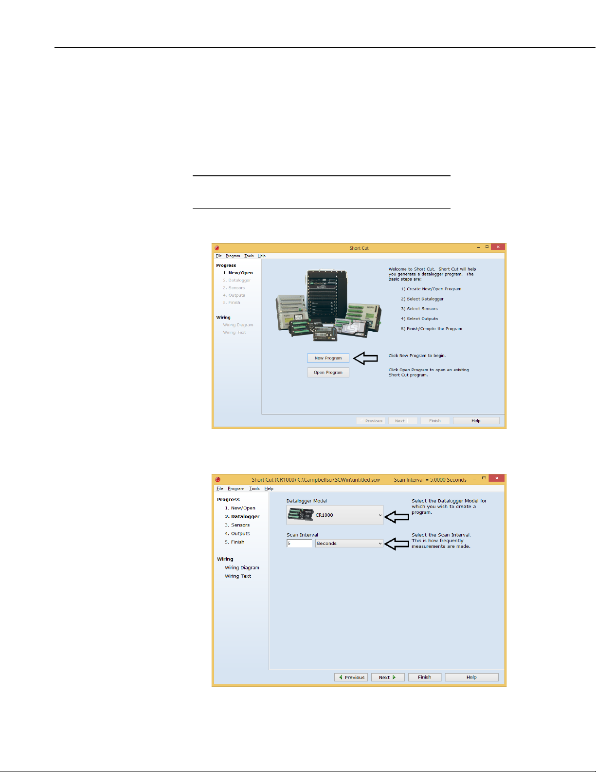
1. Open Short Cut. Click New Program.
2. Select Datalogger Model and Scan Interval (60 second or higher scan
interval is recommended). Click Next.
2
Page 13
SR50A-Series Sonic Ranging Sensors
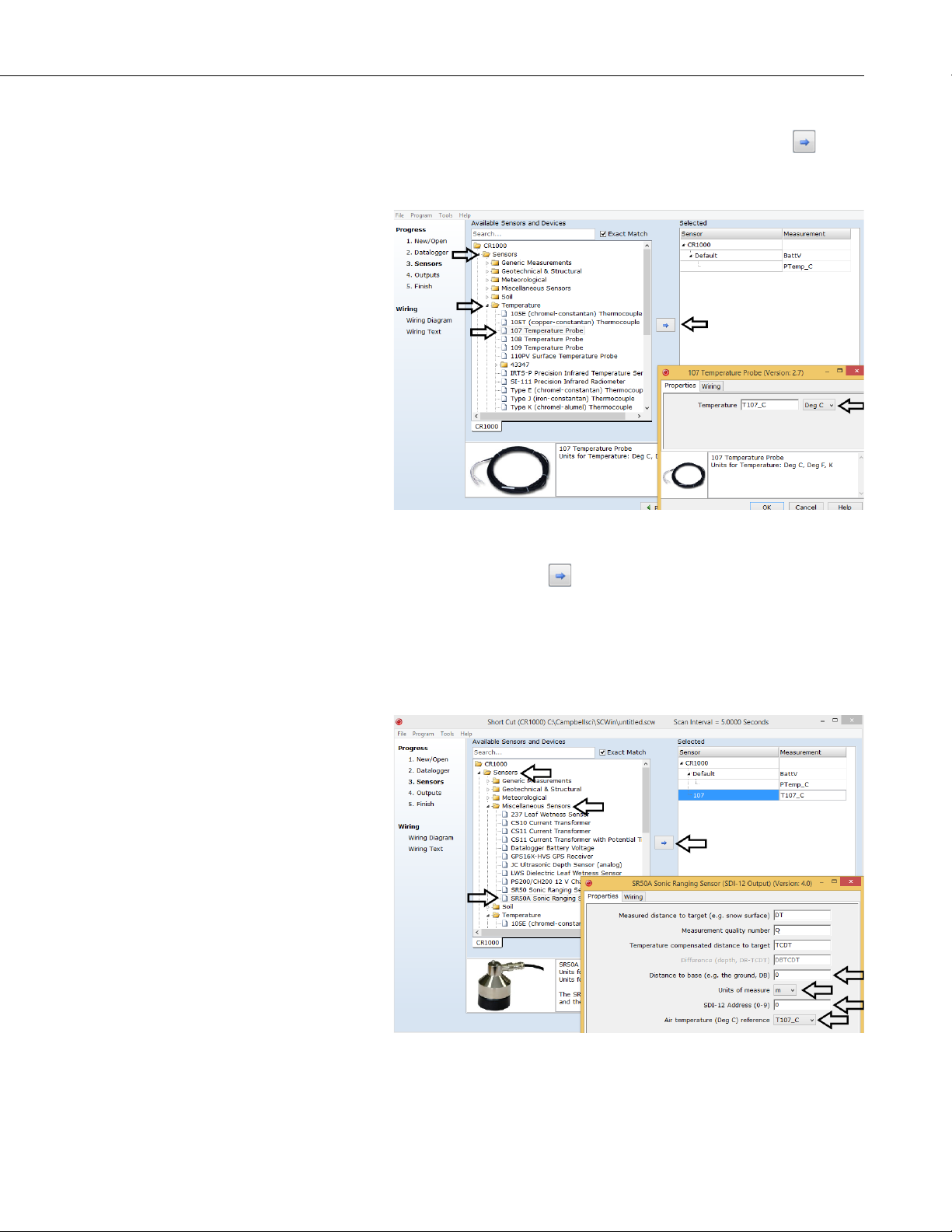
3. Under the Available Sensors and Devices list, select the Sensors |
Temperature folder. Select 107 Temperature Probe. Click to move
the selection to the Selected device window. Use the data default of degree
Celsius.
4. Under the Available Sensors and Devices list, select the Sensors |
Miscellaneous Sensors folder. Select SR50A Sonic Ranging Sensor
(SDI-12 Output). Click to move the selection to the Selected device
window. Data defaults to meters, which can be changed by clicking the
Unit of measure box and selecting cm, ft, or in. Enter the Distance to
base, which is the distance from the SR50A’s wire mesh face to the
ground. SDI-12 Address defaults to 0. Enter the correct SDI-12 Address
for the SR50A if it has been changed from the factory-set default value.
Click on the Air temperature (Deg C) reference box and select T107_C.
3
Page 14
SR50A-Series Sonic Ranging Sensors
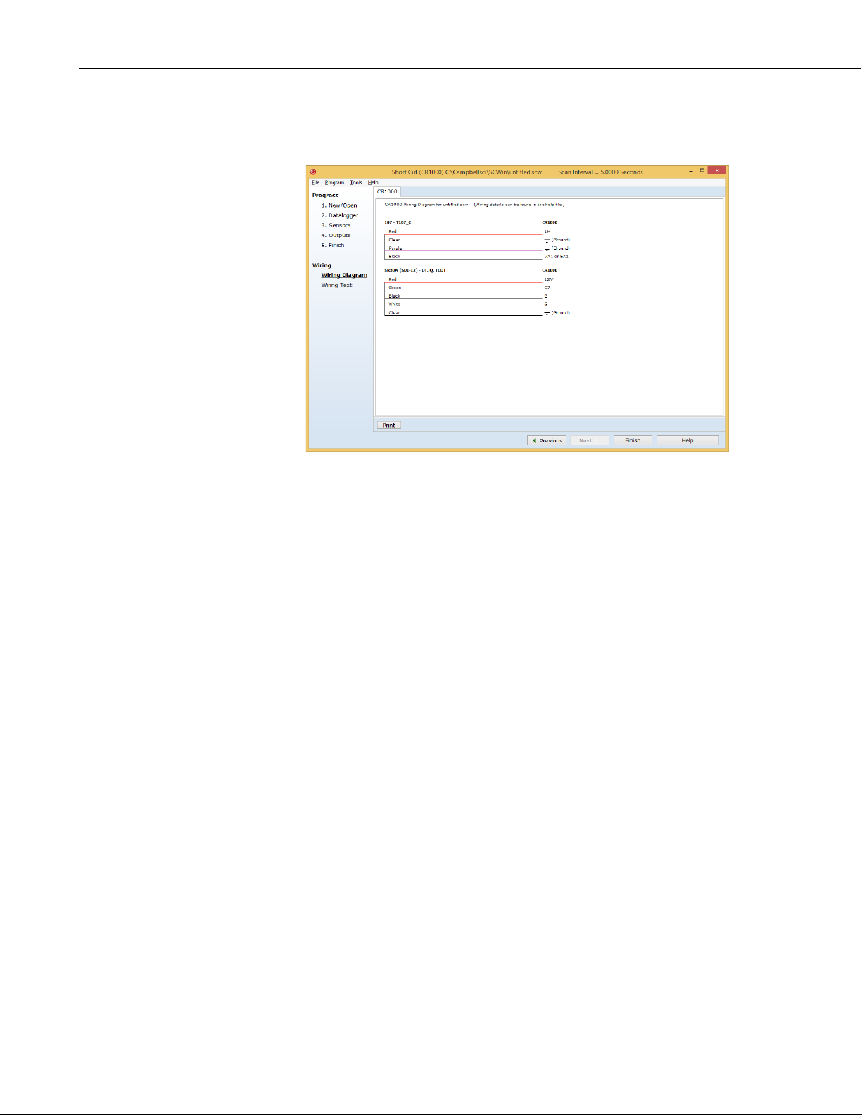
5. After selecting the sensors, click Wiring Diagram to see how the sensor is
to be wired to the datalogger. The wiring diagram can be printed now or
after more sensors are added.
5. Overview
6. Select any other sensors you have, then finish the remaining Short Cut
steps to complete the program. The remaining steps are outlined in Short
Cut Help, which is accessed by clicking on Help | Contents |
Programming Steps.
7. If LoggerNet, PC200W, PC400, or RTDAQ is running on your PC, and the
PC to datalogger connection is active, you can click Finish in Short Cut
and you will be prompted to send the program just created to the
datalogger.
8. If the sensor is connected to the datalogger, as shown in the wiring
diagram in step 5, check the output of the sensor in the datalogger support
software data display to make sure it is making reasonable measurements.
The SR50A-series sensors measure the distance from the sensor to a target.
They determine the distance to a target by sending out ultrasonic pulses
(50 kHz) and listening for the returning echoes that are reflected from the
target. The time from transmissions to return of the echo is the basis for
obtaining the distance measurement.
Since the speed of sound in air varies with temperature, an independent
temperature measurement is required to compensate the distance reading for
these sensors. A simple calculation is applied to initial readings for this
purpose.
4
The SR50A-series sensors are capable of picking up small targets or targets
that are highly absorptive to sound, such as low density snow. They use a
unique echo-processing algorithm to help ensure measurement reliability. If
desired, these sensors can also output a data value indicative of measurement
quality.
Page 15

SR50A-Series Sonic Ranging Sensors
NOTE
The SR50A-series sensors meet the stringent requirements of snow depth
measurement that make them well suited for a variety of other applications.
The SR50A and SR50AH have rugged aluminum chassis that withstand many
environments, but the aluminum chassis is not suitable for marine (salty)
environments. The SR50A-316SS has a stainless-steel chassis with a parylene-
coated transducer head that allows the sensor to be used in marine or other
corrosive environments. The SR50AH includes a heater that prevents ice from
coating the transducer, but the heater increases the power consumption of the
sensor; see Appendix F, SR50AH Heater Operation
(p. F-1), for more
information. Throughout this document SR50A will refer to all of the models
unless specified otherwise.
Sonic ranging sensors with integrated temperature sensors are also
available from Campbell Scientific; see the SR50AT, SR50AT316SS, and SR50ATH manual for more information.
SDI-12, RS-232, and RS-485 output options are available for measuring the
SR50A. The SR50A is factory configured as an SDI-12 sensor (address 0)
because Campbell dataloggers typically use the SDI-12 format. To use the
RS-232 or RS-485 format, three jumpers inside the SR50A need to be moved
(Section 9.1, Disassembly/Assembly Procedures
Jumper Settings
(p. D-1), for more information.
(p. C-1)). Refer to Appendix D, RS-232 and RS-485 Operation
(p. 15), and Appendix C,
6. Specifications
Features:
Power Requirements: 9 to 18 Vdc
Quiescent Power
Consumption (no heater)
SDI-12 Mode: < 1.0 mA
< 2.0 mA (> 9600 bps)
Active Power
Consumption (no heater): 250 mA typical
Measurement Time: Less than 1.0 s typical for RS-232 or
1.2 s typical for SDI-12 measurements.
Selectable Outputs: SDI-12 (version 1.3)
RS-232 (1200 to 38400 bps)
RS-485 (1200 to 38400 bps)
• Wide operating temperature range
• Compatible with Campbell Scientific CRBasic dataloggers:
CR200(X) series, CR300 series, CR6 series, CR800 series, CR1000,
CR3000, and CR5000
RS-232/RS-485 Modes: < 1.25 mA (≤ 9600 bps),
RS-485 measurements.
Measurement Range: 0.5 to 10 m (1.6 to 32.8 ft)
5
Page 16

SR50A-Series Sonic Ranging Sensors
Accuracy: ±1 cm (±0.4 in) or 0.4% of distance to
Accuracy specification excludes errors in
Resolution: 0.25 mm (0.01 in)
Required Beam Angle Clearance: 30°
Operating Temperature Range: –45 to 50 °C
Maximum Cable Length: SDI-12 60 m (196.9 ft)
RS-232 (9600 bps or less) 30 m (98.4 ft)
RS-485 300 m (984.3 ft)
Cable Type: 4 conductor, 2-twisted pair, 22 awg,
Chassis Types: Aluminum or 316L stainless steel
target, whichever is greater.
the temperature compensation. An external
temperature compensation is required for
the SR50A.
1
Santoprene jacket
Sensor Length: 10.1 cm (4 in)
Sensor Diameter: 7.6 cm (3 in)
Sensor Weight (no cable)
Aluminum Chassis:
0.4 kg (0.88 lb)
Stainless-Steel Chassis: 0.795 kg (1.75 lb)
Cable Weight (15 ft): 0.25 kg (0.55 lb)
IP Rating
Electrical Housing:
IP67
Transducer: IP64
Compliance: This device complies with Part 15 of the
USA Federal Communications
Commission (FCC) Rules. Operation in
the USA is subject to the following two
conditions:
1. This device may not cause harmful
interference.
2. This device must accept any
interference received, including
interference that may cause undesired
operation.
6
View the EU Declaration of Conformity at
• www.campbellsci.com/sr50a
• www.campbellsci.com/sr50a-316ss
• www.campbellsci.com/sr50ah
1
Power supply must not drop below 11.0 V or heavier gage wire is required.
Page 17
7. Installation
( )
CONE
0.=
CONE
heightradius
268
SR50A-Series Sonic Ranging Sensors
If you are programming your datalogger with Short Cut, skip Section 7.2,
SDI-12 Wiring
does this work for you. See Section 4, QuickStart
(p. 10), and Section 7.3, SDI-12 Programming (p. 10). Short Cut
(p. 2), for a Short Cut tutorial.
If not using SDI-12, refer to Appendix D, RS-232 and RS-485 Operation
for wiring and programming information.
7.1 Sensor Mounting
7.1.1 Beam Angle
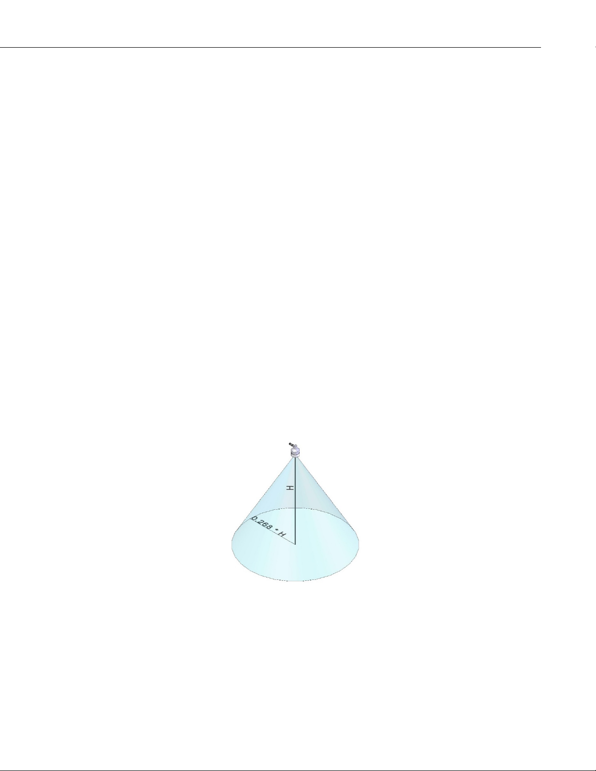
When mounting the SR50A, the sensor’s beam angle needs to be considered.
Mount the SR50A perpendicular to the intended target surface. The SR50A has
a beam angle of approximately 30 degrees. This means that objects outside this
30-degree beam will not be detected nor interfere with the intended target. Any
unwanted target must be outside the 30-degree beam angle.
Determine the required clearance for the beam angle using the following
formula and FIGURE 7-1.
Where,
CONE
height
CONE
radius
Clearance Radius formula:
= the distance to base (Section 7.1.2.1, Reference Point (p. 8))
= clearance radius in the same measurement units as the CONE
(p. D-1),
height
7.1.2 Mounting Height
FIGURE 7-1. Beam Angle Clearance
Mount the SR50A so that the face of the transducer is at least 50 cm (19.7 in)
away from the target. However, mounting the sensor too far from the target can
increase the absolute error increases. For example, if your sensor is measuring
snow depth in an area that will likely not exceed 1.25 m (4.1 ft) then a good
7
Page 18
SR50A-Series Sonic Ranging Sensors
height to mount the sensor will be 1.75 to 2.0 m (5.74 to 6.56 ft). Mounting the
sensor at a 4 m (13.1 ft) height can result in larger snow depth errors.
7.1.2.1 Reference Point
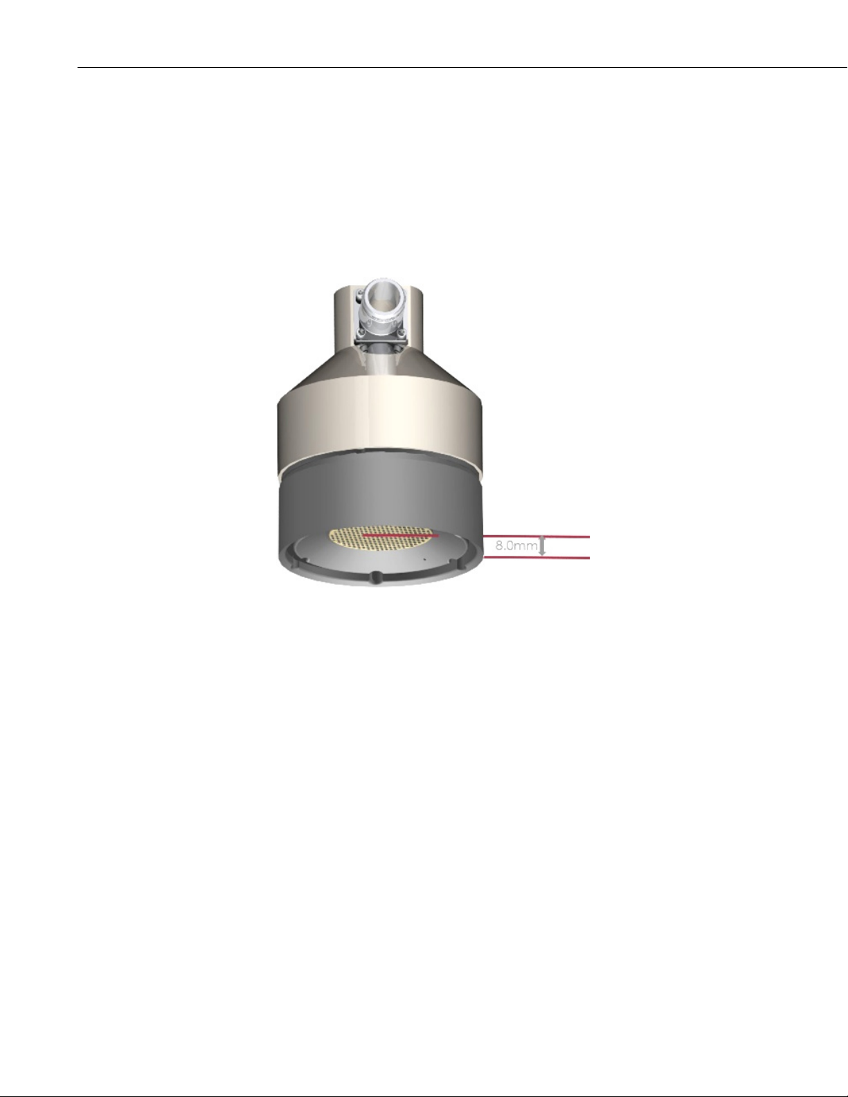
The front grill on the ultrasonic transducer is used for the reference for the
distance values. Because of the difficulty of measuring from the grill, most
users measure the distance from the target to the outer edge of the plastic
transducer housing (FIGURE 7-2), and then add 8 mm (0.3 in) to the measured
distance.
FIGURE 7-2. Distance from Edge of Transducer Housing to Grill
7.1.3 Mounting Options
To achieve an unobstructed view for the SR50A’s beam, the SR50A is
typically mounted to a tripod mast, tower leg, or user-supplied pole using the
CM206 6-ft crossarm or a pipe with a 1-inch to 1.75-inch outer diameter. The
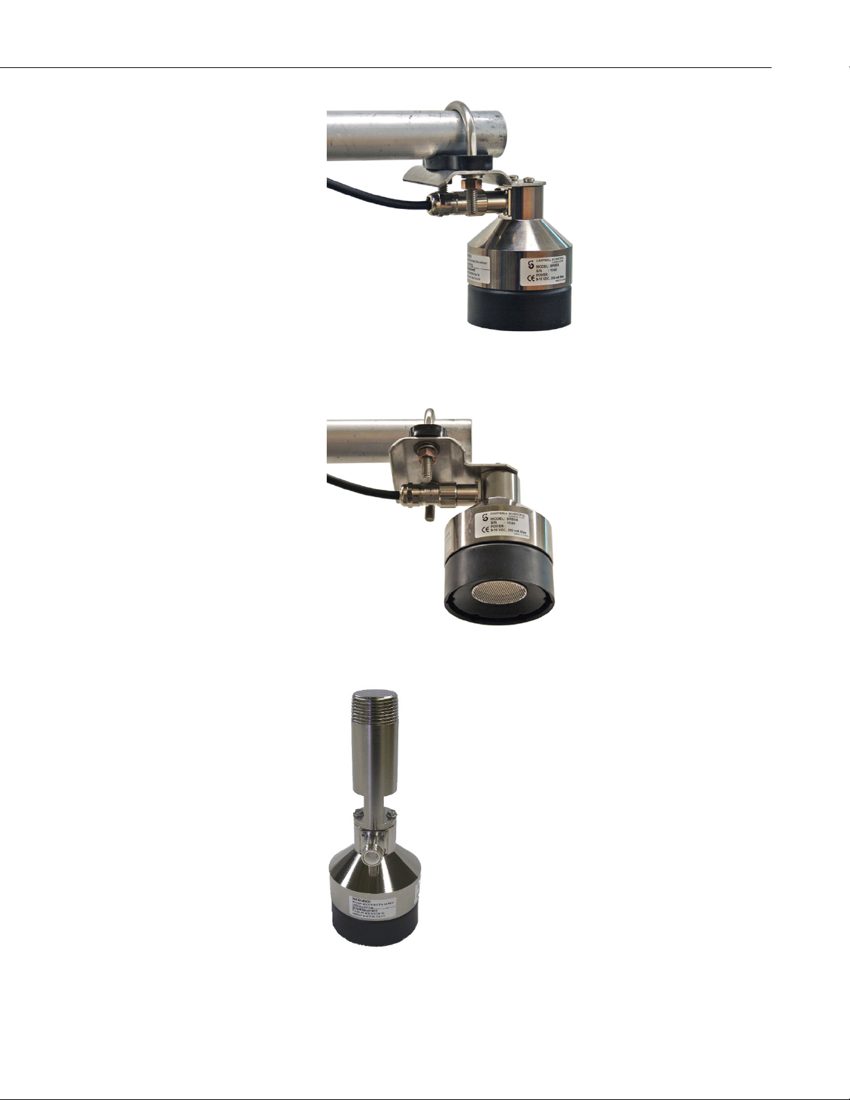
19517 mounting kit attaches directly to the crossarm or pipe. FIGURE 7-3 and
FIGURE 7-4 show a couple of angles of the SR50A mounted to a crossarm
using the 19517. A U-bolt mounts the bracket to the crossarm and two screws
fasten the SR50A to the bracket.
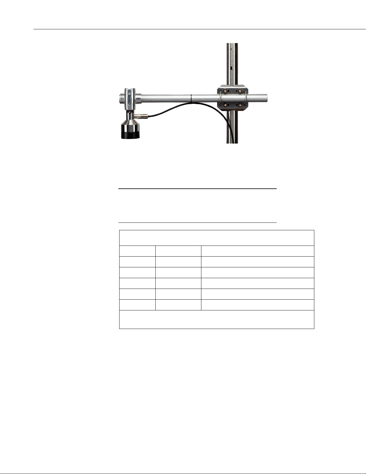
The 19484 mounting stem (FIGURE 7-5) attaches to the crossarm using the
17953 Nu-Rail fitting (FIGURE 7-6), CM220 right-angle mount, CM230
adjustable-angle mount, or CM230XL extended adjustable-angle mount. Use
the CM230 or CM230XL if the surface is at an angle.
8
Page 19
SR50A-Series Sonic Ranging Sensors
FIGURE 7-3. SR50A Mounted to a Crossarm via the 19517 Mounting
Kit
FIGURE 7-4. Another Angle of the 19517 Mounting Kit
FIGURE 7-5. SR50A Mounted to a 19484 Mounting Stem
9
Page 20
SR50A-Series Sonic Ranging Sensors
TABLE 7-1. Wire Color, Function, and Datalogger Connection
CAUTION
FIGURE 7-6. SR50A-316SS Mounted to a Crossarm with the 19484
and Nu-Rail Fitting
7.2 SDI-12 Wiring
Power down your system before wiring the SR50A. Never
operate the sensor with the shield wire disconnected. The
shield wire plays an important role in noise emissions and
susceptibility as well as transient protection.
Wire Color Wire Function Datalogger Connection Terminal
Black Power Ground
Red Power
Green SDI-12 signal Control Port1 or U configured for SDI-12
White Ground
Clear Shield
1
Dedicated SDI-12 port on CR5000
2
U channels are automatically configured by the measurement instruction.
To use more than one probe per datalogger, either connect the different sensors
to different terminals on the datalogger or change the SDI-12 addresses of the
sensors and wire them to the same terminal. Using the SDI-12 address reduces
the use of ports on the datalogger and allows sensors to be connected in a
daisy-chain that can minimize cable runs in some applications.
7.3 SDI-12 Programming
Short Cut is the best source for up-to-date datalogger programming code.
Programming code is needed when:
• Creating a program for a new datalogger installation
• Adding sensors to an existing datalogger program
G
12V
G
G
2
10
Page 21

If your data acquisition requirements are simple, you can probably create and
NOTE
maintain a datalogger program exclusively with Short Cut. If your data
acquisition needs are more complex, the files that Short Cut creates are a great
source for programming code to start a new program or add to an existing
custom program.
Short Cut cannot edit programs after they are imported and edited
in CRBasic Editor.
A Short Cut tutorial is available in Section 4, QuickStart (p. 2). If you wish to
import Short Cut code into CRBasic Editor to create or add to a customized
program, follow the procedure in Appendix A, Importing Short Cut Code Into
CRBasic Editor
(p. A-1). Programming basics for CRBasic dataloggers are in the
following section. Complete program examples for select CRBasic dataloggers
can be found in Appendix B, Example Programs
and programming examples for Edlog dataloggers are provided at
www.campbellsci.com\old-manuals.
7.3.1 SDI12Recorder() Instruction
The SDI12Recorder() measurement instruction programs CRBasic
dataloggers (CR200(X) series, CR300 series, CR6 series, CR800-series,
CR1000, CR3000, and CR5000) to measure the sensor. This instruction sends a
request to the sensor to make a measurement and then retrieves the
measurement from the sensor. See Section 8.3, SDI-12 Measurements
more information.
SR50A-Series Sonic Ranging Sensors
(p. B-1). Programming basics
(p. 13), for
8. Operation
When using a CR200(X), the SDI12Recorder() instruction has the following
syntax:
SDI12Recorder(Destination,OutString,Multiplier,Offset)
For the other CRBasic dataloggers, the SDI12Recorder() instruction has the
following syntax:
SDI12Recorder(Destination, SDIPort, SDIAddress, “SDICommand”,
Multiplier, Offset)
The SR50A performs multiple echo processing regardless of output formats. It
bases every measurement on several readings and applies an algorithm to
improve measurement reliability.
The distance to target readings that are obtained from the sensor are referenced
from the metal mesh on the face of the transducer. The SR50A projects an
ultrasonic beam that can pick up objects in its field of view that is 30° or less.
The closest object to the sensor will be detected if it is within this field of view.
Unwanted objects must be outside the field of view. If a target is in motion, the
SR50A may reject a reading if the target distance changes at a rate of 4
centimeters per second or more.
The SR50A completes a measurement and output the data typically in 1
second. In RS-232 and RS-485 serial modes, the data is completed within one
second for baud rates of 9600 bps and above. The total time for an SDI-12
11
Page 22
SR50A-Series Sonic Ranging Sensors
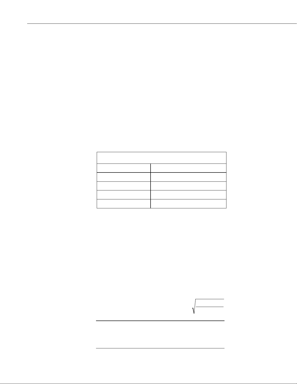
TABLE 8-1. Quality Number Description
273.15
KELVIN
T
READING
=DISTANCE
SR50A
°
CAUTION
measurement can exceed 1 second due to the long communication times
associated with the 1200 bps data rate.
If the SR50A rejects a reading or does not detect a target, zero will be output
for distance to target or –999 for depth values.
8.1 Quality Numbers
Measurement quality numbers are available with the output data; these
numbers indicate the measurement certainty (TABLE 8-1). Quality numbers
have no units of measure and typically vary from 152 to 600. Numbers that are
between 152 and 210 indicate good quality measurements. Zero indicates that
the reading was not obtained. Numbers greater than 300 indicate a degree of
uncertainty in the measurement. Causes of high numbers include:
• sensor is not perpendicular to the target surface
• target is small and reflects little sound
• target surface is rough or uneven
• target surface is a poor reflector of sound (extremely low density
snow)
Quality Number Range Quality Range Description
0 Not able to read distance
152 to 210 Good measurement quality numbers
210 to 300 Reduced echo signal strength
300 to 600 High measurement uncertainty
Although not necessary, quality numbers provide useful information such as
surface density in snow monitoring applications. Please note that quality
number values may increase during snowfall events consisting of low-density
snow.
8.2 Temperature Compensation
The SR50A does not include a temperature sensor to compensate for the speedof-sound variations in air temperature. Temperature corrections for the speed of
sound will need to be applied to the readings. Use a reliable and accurate
probe, such as the 107, to measure air temperature. A radiation shield is also
required when the temperature probe will be exposed to solar radiation.
Temperature compensation must be applied to the sensor output using the
following formula:
The SR50A calculates a distance reading using the speed
of sound at 0 °C (331.4 m/s). If the temperature
compensation formula is not applied, the distance values
will not be accurate for temperatures other than 0 °C.
12
Page 23
8.3 SDI-12 Measurements
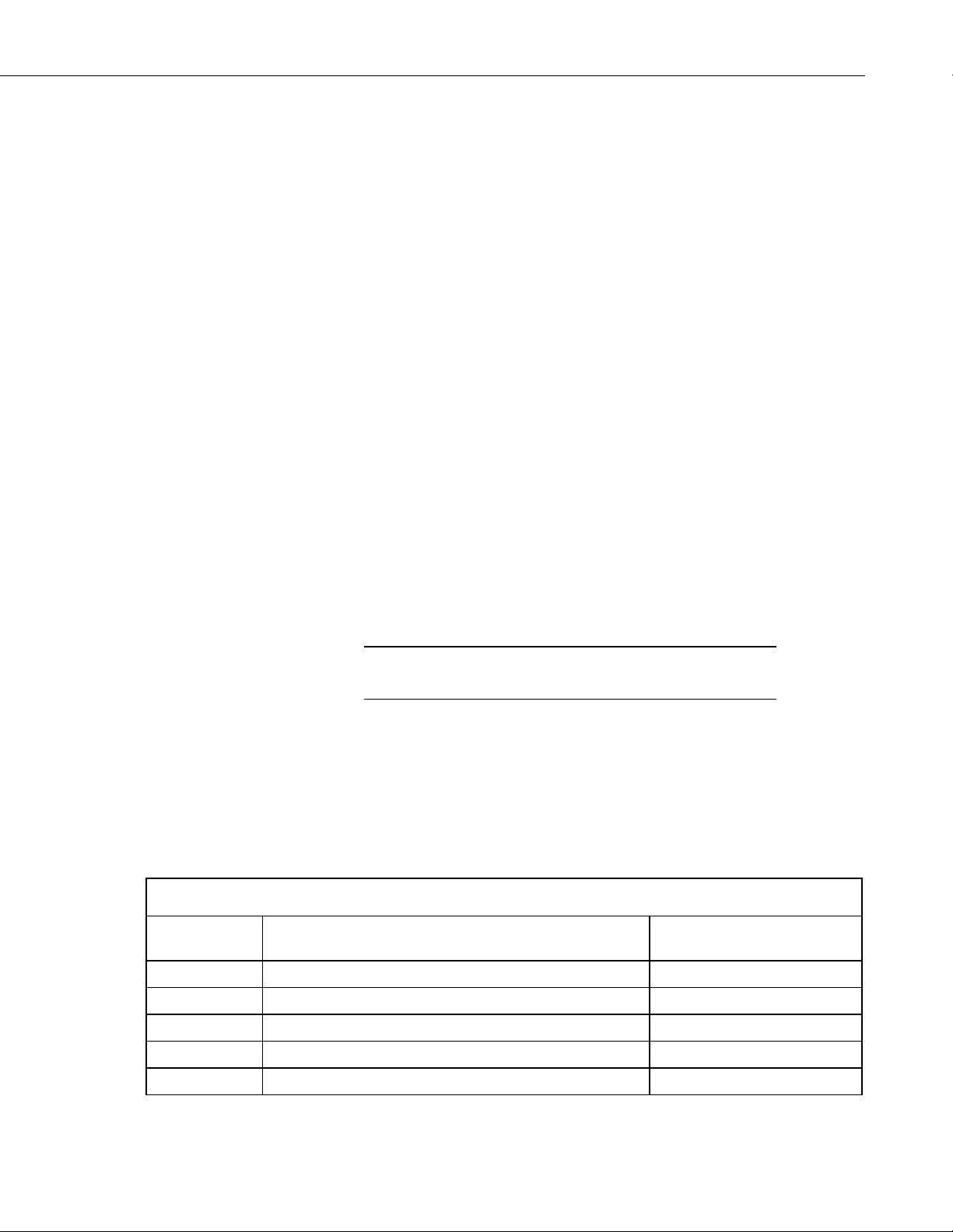
TABLE 8-2. SDI-12 Commands
NOTE
8.3.1 SDI-12 Addresses
The SR50A can be set to one of ten addresses (0 to 9) which allows up to ten
sensors to be connected to a single digital I/O channel (control port) of an
SDI-12 datalogger.
The SR50A is shipped from the factory with the address set to 0. The address
on the SR50A can be changed by sending an SDI-12 change address command.
The change address command can be issued from most SDI-12 recorders. For
some Campbell Scientific dataloggers, the SDI-12 transparent mode will need
to be entered to change the address.
When it is necessary to measure more than one SR50A, it is easiest to use a
different control port for each SR50A instead of changing the address. If
additional control ports are not available, then the address will need to be
changed.
To change the address of a sensor that has the default address of 0 to the
address of 1 the following command can be sent:
“0A1!”
SR50A-Series Sonic Ranging Sensors
Only one sensor of the same address should be connected when using the
change address command.
8.3.2 SDI-12 Commands
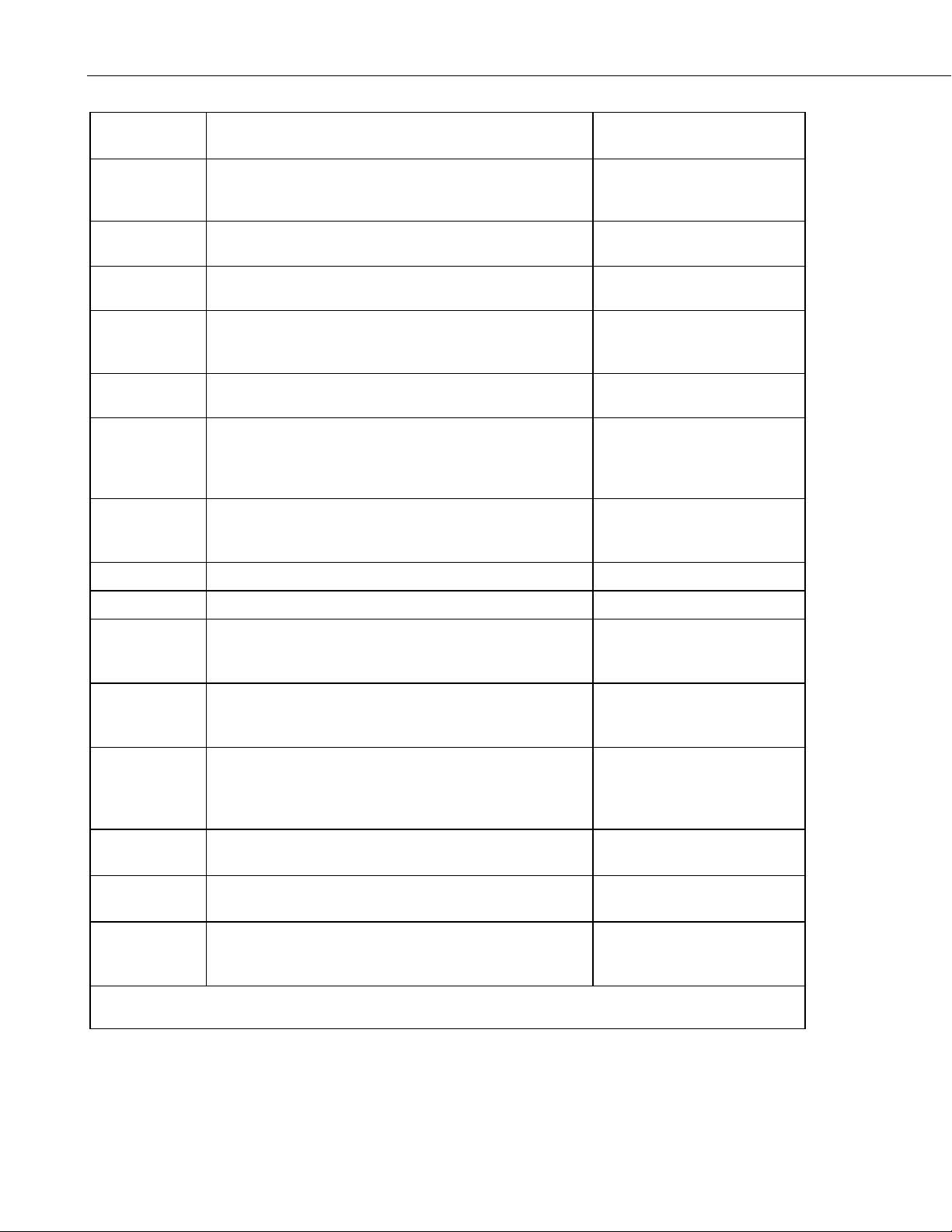
The SDI-12 protocol supports the SDI-12 commands listed in TABLE 8-2.
The SR50A needs to be powered for 1.5 s before it can receive an
SDI-12 command.
The different commands are entered as options in the SDI-12 recorder
instruction. The major difference between the various measurement commands
are the data values that are returned. The user has the option to output the
distance to target in either meters or feet, or to include the measurement quality
numbers.
If the SR50A is unable to detect a proper echo for a measurement, the sensor
will return a zero value for the distance to target value.
SDI-12
Command
aM! Distance-Meters D
Command Function/Description
Values Returned
aM1! Distance-Meters, Quality Number D, Q
aM4! Snow Depth Meters, Quality Number, Temperature SD, Q, T
aM5! Distance-Inches D
aM6! Distance-Inches, Quality Number D, Q
13
Page 24
SR50A-Series Sonic Ranging Sensors
SDI-12
Command
aMC!
aMCn!
aC!
aCn!
aCC!
aCCn!
Measurement Commands with Checksum
See aM and aM1- aM8
Concurrent Measurement Command
Distance-Meters
Concurrent Measurements
Same as M1 through M8
Concurrent Measurement Commands with Checksum. See
aM and aM1- aM8
Command Function/Description
aD0! Send Data
aV! Verification command
Output is the same as
Same as M1 through M8
Output is the same as
Dependent upon command
S1 = Firmware Signature
S2 = BootRom Signature
WD = Watch Dog Errors
013CAMPBELLSR50A 2.0SN
aI! Send Identification
?! Address Query a
Values Returned
aM, aM1-aM9
Checksum is added
D
Output is the
aM, aM1-aM8
Checksum is added
Sent
S1,S2,V,WD
SN = Serial number
(5 digits)
aAb! Change Address command b is the new address
aXM;D.DDD!
Extended
command
aXI;DDD.DD!
Extended
command
aXT;CC.CC!
Extended
command
aR0!
aR1!
Set the distance to ground parameter in the SR50A. The
distance must be in meters with no more than three
decimal places.
Set the distance to ground parameter in the SR50A. The
distance must be in Inches with no more than two decimal
places.
Provide the SR50A with a temperature value to perform on
board temperature compensation. The temperature must be
in degrees Celsius with a maximum of seven characters
including sign and decimal.
Returns the distance to ground setting in the SR50A. The
units returned are in meters
Returns the distance to ground setting in the SR50A. The
units returned are in inches
Address is returned
Address is returned
Address is returned
Returns the temperature sent to the SR50A for internal
aR2!
temperature compensation. This value remains the same
unless power is cycled or a new temperature values is sent.
Where a = address of SDI-12 device.
Where n = numbers 1 to 9
A
A
A
DG
DG
T
14
Page 25
SR50A-Series Sonic Ranging Sensors
CAUTION
CAUTION
9. Maintenance and Troubleshooting
The SR50A’s electrostatic transducer requires equal pressure on both sides.
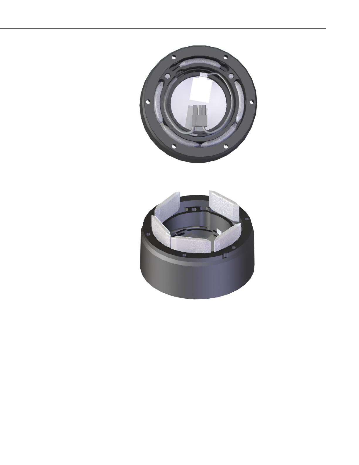
Vent holes in the transducer housing are used to equalize pressure. Desiccant
(pn 4091) placed inside the transducer housing helps prevent condensing
humidity. Regularly inspect the desiccant and, if required, replace it. Desiccant
capable of absorbing moisture is blue. Once the desiccant becomes saturated,
the color changes from blue to pink. In humid environments, replace the
desiccant more frequently. Inspection or replacement of the desiccant requires
the SR50A to be disassembled (Section 9.1, Disassembly/Assembly Procedures
(p. 15)).
Replace the transducer assembly every three years if it is not in a humid
environment. Replace the transducer housing assembly every year in humid
environments.
• Standard SR50A housing and maintenance kit: pn 19486.
• SR50A open-faced housing and maintenance kit (used with the
SR50A-316SS model): pn 32570.
• SR50AH housing and maintenance kit: pn 32571.
9.1 Disassembly/Assembly Procedures
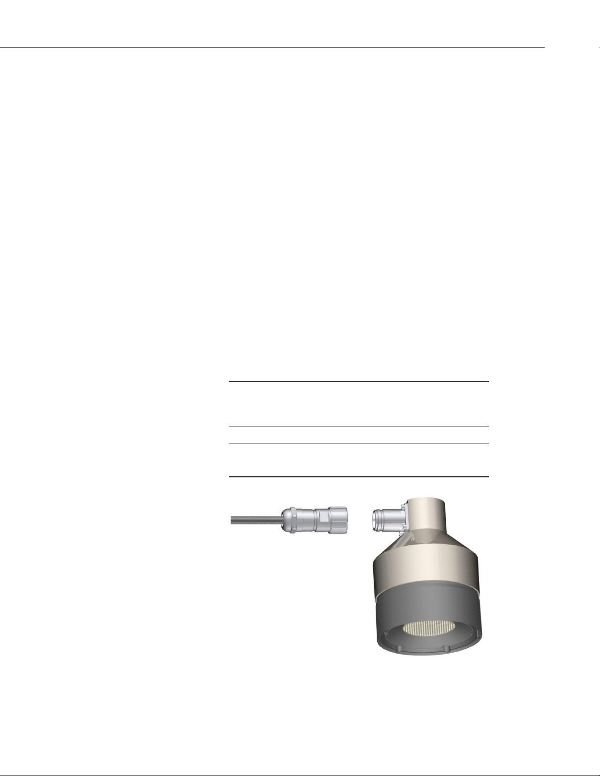
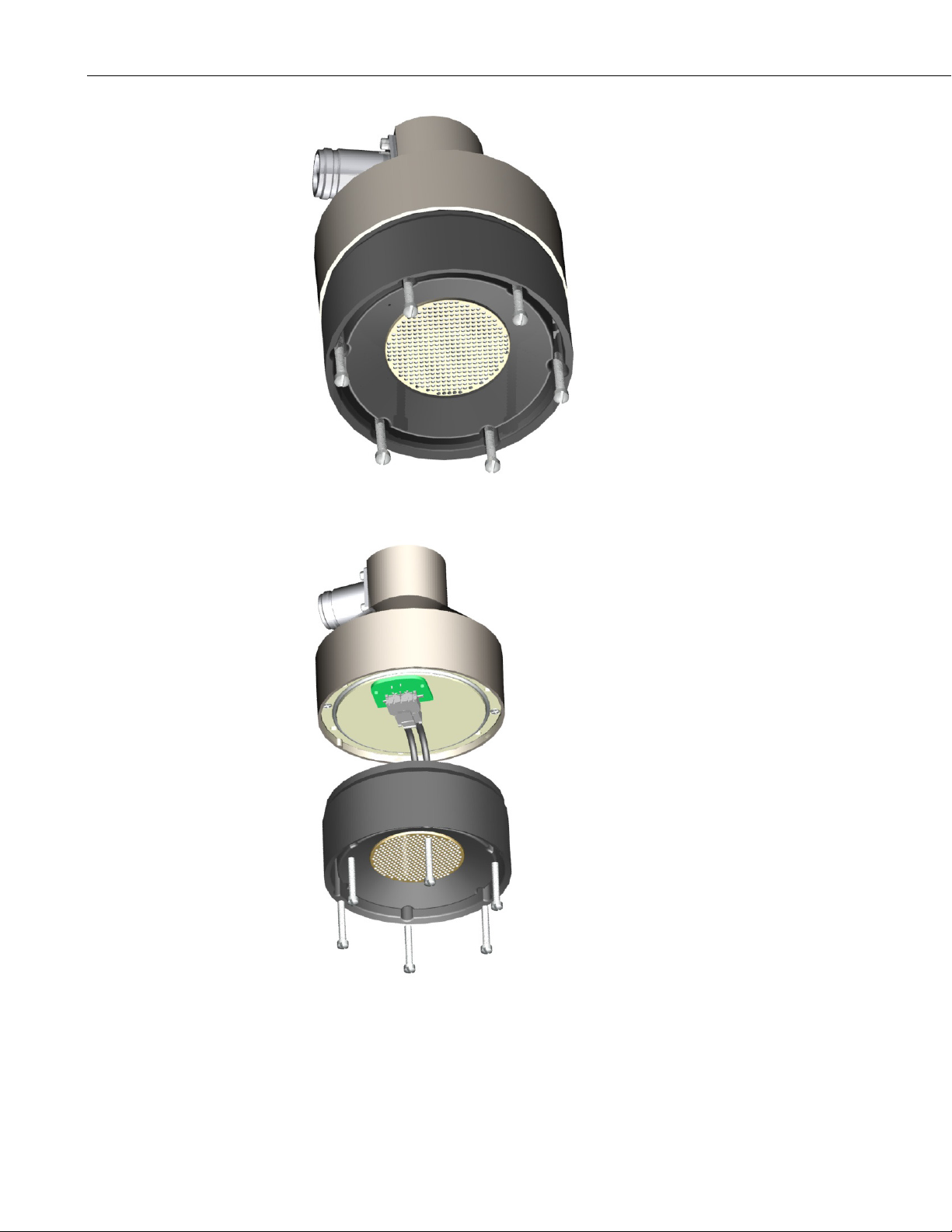
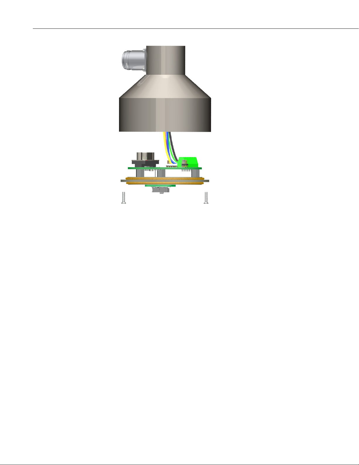
FIGURES 9-1 through 9-6 show the procedure for disassembling the SR50A.
Disassembly is required to inspect or replace the desiccant, and to change the
transducer and the option jumpers.
Before proceeding with any maintenance, always retrieve
the data first. Campbell Scientific also recommends saving
the datalogger program.
Always disconnect the SR50A from the datalogger or the
connector before disassembling.
FIGURE 9-1. Disconnect Cable from Sensor
15
Page 26
SR50A-Series Sonic Ranging Sensors
FIGURE 9-2. Remove Six Screws from the Transducer Housing
16
FIGURE 9-3. Remove Transducer Housing and Disconnect Wires
Page 27
SR50A-Series Sonic Ranging Sensors
FIGURE 9-4. Location of Desiccant in Transducer Housing Assembly
FIGURE 9-5. Remove and Replace Desiccant
17
Page 28
SR50A-Series Sonic Ranging Sensors
FIGURE 9-6. Remove the Two Flat Phillips Screws to Expose the PCB
Carefully reassemble in reverse order.
9.2 Data Interpretation and Filtering
9.2.1 Data Interpretation
Although not common, the SR50A can occasionally output invalid reading
indicators if it was unable to obtain a measurement. For distance to target
values, a 0.0 reading is usually output. For snow depth outputs, the error
indicator value is –999. An invalid temperature reading is also indicated by a
–999 reading. For snow depth applications, these can be easily filtered out
when analyzing the data.
Consideration should be taken in a control type application to deal with invalid
readings. For example, if the sensor is used to initiate a water level alarm,
multiple readings should be used to ensure that a single invalid reading does
not trigger the alarm condition.
9.2.2 Data Filtering
There are scenarios where the SR50A can produce values with higher than
expected errors. For example, in very low density snow, very little echo is
returned back to the sensor. The increase in echo quality numbers is an
indication of the weak signals. Under these circumstances, an SR50A can
under, or over, estimate snow depth. If the signal is too weak, the sensor will
also output a value of 0 for the distance to target. When the echoes are weak,
the sensor also automatically increases sensitivity. This makes the sensor more
18
Page 29
SR50A-Series Sonic Ranging Sensors
prone to the occasional erroneous reading from flying debris, drifting snow, or
mounting hardware just outside the beam angle.
The reason not to average values is that occasionally a number with a very high
error value is produced, skewing the average. The value should be ignored and
not averaged. Based on experience, the best technique to eliminate errors and
filter out high error readings is to take the median value. This technique also
helps to automatically filter out zero readings that can occasionally be
produced.
For example, for a given station, a reading is taken every 5 seconds for 1
minute and the median value is taken from the readings. All the programming
examples in this manual use this method for data filtering.
If 11 consecutive values are as
follows for snow depth
0.33 –1.1
0.34 0.10
0.35 0.28
–1.1 (erroneous reading) 0.32
2.0 (erroneous reading) 0.33
0.37 0.33
0.28 0.34
0.36 0.35
0.10 (high error value) 0.36
0.33 0.37
0.32 2.0
The best course of action would be to ignore the 5 lowest values and take the
6th value (0.33).
After being sorted from
low to high
19
Page 30

SR50A-Series Sonic Ranging Sensors
20
Page 31

NOTE
Appendix A. Importing Short Cut Code Into CRBasic Editor
This tutorial shows the following:
• How to import a Short Cut program into a program editor for
additional refinement
• How to import a wiring diagram from Short Cut into the comments of
a custom program
Short Cut creates files, which can be imported into CRBasic Editor. Assuming
defaults were used when Short Cut was installed, these files reside in the
C:\campbellsci\SCWin folder:
• .DEF (wiring and memory usage information)
• .CR2 (CR200(X)-series datalogger code)
• .CR300 (CR300-series datalogger code)
• .CR6 (CR6-series datalogger code)
• .CR8 (CR800-series datalogger code)
• .CR1 (CR1000 datalogger code)
• .CR3 (CR3000 datalogger code)
• .CR5 (CR5000 datalogger code)
Use the following procedure to import Short Cut code and wiring diagram into
CRBasic Editor:
1. Create the Short Cut program following the procedure in Section 4,
QuickStart
file name used when saving the Short Cut program.
2. Open CRBasic Editor.
3. Click File | Open. Assuming the default paths were used when Short Cut
was installed, navigate to C:\CampbellSci\SCWin folder. The file of
interest has the .CR2, .CR300, .CR6, .CR8, .CR1, .CR3, or .CR5
extension. Select the file and click Open.
4. Immediately save the file in a folder different from
C:\Campbellsci\SCWin, or save the file with a different file name.
Once the file is edited with CRBasic Editor, Short Cut can no
longer be used to edit the datalogger program. Change the name
of the program file or move it, or Short Cut may overwrite it next
time it is used.
5. The program can now be edited, saved, and sent to the datalogger.
6. Import wiring information to the program by opening the associated .DEF
file. Copy and paste the section beginning with heading “-Wiring for
CRXXX–” into the CRBasic program, usually at the head of the file. After
pasting, edit the information such that an apostrophe (') begins each line.
This character instructs the datalogger compiler to ignore the line when
compiling.
(p. 2). Finish the program and exit Short Cut. Make note of the
A-1
Page 32

Page 33
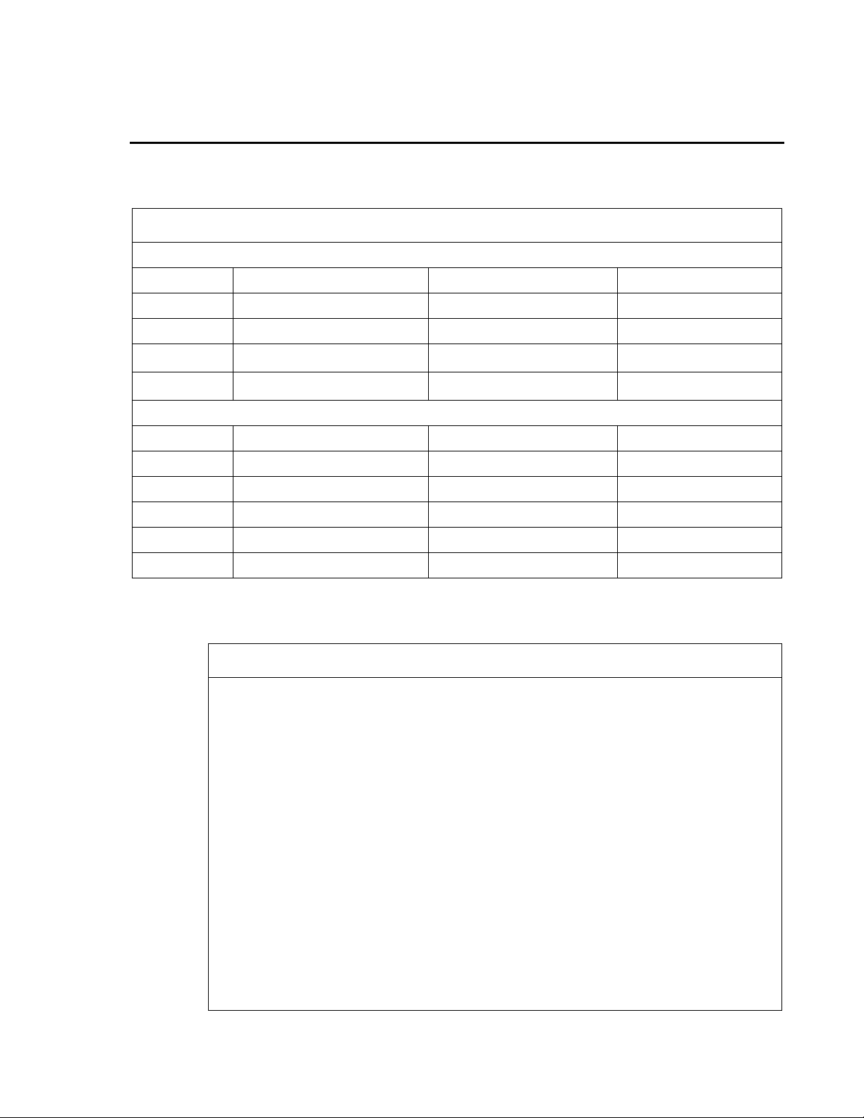
TABLE B-1. Wiring for CR1000 and CR6 SDI-12 Example Programs
⏚
⏚
⏚ ⏚
CRBasic Example B-1. CR1000 SDI-12 Program
Public BattV : Units BattV = Volts 'CR1000 battery voltage
Appendix B. Example Programs
B.1 SDI-12 Example Programs
107-L Air Temperature Sensor Wiring
Wire Color Sensor Wire Description CR1000 Wire Channels CR6 Wire Channels
Black Voltage-excitation input
Red Analog-voltage output
Purple Bridge resistor lead
Shield EMF shield
VX1 U2
SE1 U1
SR50A-L Configured for SDI-12 Wiring
Wire Color Sensor Wire Description CR1000 Wire Channels CR6 Wire Channels
Red Power source
Green SDI-12 I/O
White Not used
Black Ground
Shield Shield/Earth ground
12V 12V
C1 C1
G G
G G
G G
B.1.1 CR1000 SDI-12 Program
'CR1000
'This program contains a number of features not found in Short Cut.
'
'The initial distance value from the SR50A head to the ground is
'measured by setting the flag SR50A_MID to TRUE. Set this flag after
'installing the SR50A in the field. Setting this flag will initiate
'a measurement cycle and the resulting value stored as the initial
'distance. The initial distance is used to calculate snow depth.
'The PreserveVariables instruction is used to store the initial
'distance in non-volatile memory. If power is lost at the site the
'initial distance value will be restored.'
'A control flag is used to initiate the SR50A measurement cycle. This
'allows for manual control in the field to check distances without
'waiting for the correct time interval to occur. It is also used by
'the datalogger to initiate an automated measurement cycle.
'
'Every measurement cycle is composed of 11 individual measurements
'that are spatially sorted to eliminate any low or high values.
'One measurement is made with each scan. This program has a 10
'second scan rate so it will take 100 seconds to do all 11 scans or
'1 minute and 40 seconds.
'Declare Variables and Units
B-1
Page 34

Appendix B. Example Programs
Public PnlTmp_C : Units PnlTmp_C = °C 'CR1000 panel temperature
'actual storage time to get 11 measurements completed.
Public AirTempC : Units AirTempC = °C 'Air temperature
Public SR50A_Raw(2)
Alias SR50A_Raw(1) = DT : Units DT = meters 'Distance from the SR50A.
Alias SR50A_Raw(2) = RawQ : Units RawQ = unitless 'Quality number.
'Array to hold 11 SR50A measurements composed of a distance and
'quality number.
Public SR50A(11,2)
'Sorted array of 11 SR50A measurements composed of a distance and
'quality number. Measurements are sorted by the distance value from
'smallest to largest.
Public Result_SR50A(11,2)
Public TCDT : Units TCDT = meters 'Temperature corrected distance
Public Q : Units Q = unitless 'Quality number
Public Inital_Dist : Units Inital_Dist = meters 'Distance to ground.
Public Snow_Depth : Units Snow_Depth = meters 'Snow depth.
'Controls SR50A measurement. This flag can be manually controlled to
'run tests in the field or is automatically set 2 minutes before the
'hourly data storage interval. This is done so 11 measurements can
'be made and sorted before the values are stored.
Public SR50ACtrl As Boolean
'Set this flag to measure and store the initial distance from the
'SR50A to the ground.
Public SR50A_MID As Boolean
Dim n 'used as a counter
'Define Data Tables
DataTable(Daily,True,-1)
DataInterval(0,1440,Min,10)
Minimum(1,BattV,FP2,False,False)
Maximum (1,BattV,FP2,False,False)
Minimum(1,PnlTmp_C,FP2,False,False)
Maximum (1,PnlTmp_C,FP2,False,False)
EndTable
DataTable (Hour,True,-1 )
DataInterval (0,60,Min,10)
Sample (1,AirTempC,FP2)
Sample (1,TCDT,IEEE4)
Sample (1,Q,FP2)
EndTable
PreserveVariables
'Main Program
BeginProg
'Main Scan
n = 1
Scan(10,Sec,1,0)
'Battery Voltage measurement 'BattV'
Battery(BattV)
'Wiring Panel Temperature measurement 'PnlTmp_C'
PanelTemp(PnlTmp_C,_60Hz)
'107 Temperature Probe measurement 'AirTempC'
Therm107(AirTempC,1,1,1,0,_60Hz,1,0)
'Automated snow depth measurement. Must occur two minutes before
B-2
Page 35

Appendix B. Example Programs
If TimeIntoInterval (58,60,Min) Then
EndProg
CRBasic Example B-2. CR6 SDI-12 Program
'CR6
'Declare Variables and Units
SR50ACtrl = True
EndIf
'Set this flag to true to get the initial distance from the SR50A
'to the ground.
If SR50A_MID Then SR50ACtrl = True
'Logic to make 11 snow depth measurements, sort them, and store
'the corrected values.
If SR50ACtrl Then
'SR50A Sonic Ranging Sensor (SDI-12 Output) measurements
'DT' & 'Q'
SDI12Recorder(SR50A_Raw(),1,"0","M1!",1,0)
'Calculate the temperature corrected distance.
SR50A(n,1) = SR50A_Raw(1)*SQR((AirTempC+273.15)/273.15)
SR50A(n,2) = SR50A_Raw(2)
n += 1
If n > 11 Then
n = 1
SR50ACtrl = False
SortSpa (Result_SR50A(1,1),11,SR50A(1,1),2)
TCDT = Result_SR50A(6,1)
Q = Result_SR50A(6,2)
If SR50A_MID Then
Inital_Dist = TCDT
SR50A_MID = False
EndIf
Snow_Depth = Inital_Dist - TCDT
EndIf
EndIf
'Call Data Tables and Store Data
CallTable Daily
CallTable Hour
NextScan
B.1.2 CR6 SDI-12 Program
'This program contains a number of features not found in Short Cut.
'
'The initial distance value from the SR50A head to the ground is
'measured by setting the flag SR50A_MID to TRUE. Set this flag after
'installing the SR50A in the field. Setting this flag will initiate
'a measurement cycle and the resulting value stored as the initial
'distance. The initial distance is used to calculate snow depth.
'The PreserveVariables instruction is used to store the initial
'distance in non-volatile memory. If power is lost at the site the
'initial distance value will be restored.'
'A control flag is used to initiate the SR50A measurement cycle. This
'allows for manual control in the field to check distances without
'waiting for the correct time interval to occur. It is also used by
'the datalogger to initiate an automated measurement cycle.
'
'Every measurement cycle is composed of 11 individual measurements
'that are spatially sorted to eliminate any low or high values.
'One measurement is made with each scan. This program has a 10
'second scan rate so it will take 100 seconds to do all 11 scans or
'1 minute and 40 seconds.
B-3
Page 36

Appendix B. Example Programs
Public BattV : Units BattV = Volts 'CR6 battery voltage
'Automated snow depth measurement. Must occur two minutes before
Public PnlTmp_C : Units PnlTmp_C = °C 'CR6 panel temperature
Public AirTempC : Units AirTempC = °C 'Air temperature
'Array to hold 11 SR50A measurements composed of a distance and
'quality number.
Public SR50A(11,2)
Public SR50A_Raw(2)
Alias SR50A_Raw(1) = DT : Units DT = meters 'Distance from the SR50A.
Alias SR50A_Raw(2) = RawQ : Units RawQ = unitless 'Quality number.
'Sorted array of 11 SR50A measurements composed of a distance and
'quality number. Measurements are sorted by the distance value from
'smallest to largest.
Public Result_SR50A(11,2)
Public TCDT : Units TCDT = meters 'Temperature corrected distance
Public Q : Units Q = unitless 'Quality number
Public Inital_Dist : Units Inital_Dist = meters 'Distance to ground.
Public Snow_Depth : Units Snow_Depth = meters 'Snow depth.
'Controls SR50A measurement. This flag can be manually controlled to
'run tests in the field or is automatically set 2 minutes before the
'hourly data storage interval. This is done so 11 measurements can
'be made and sorted before the values are stored.
Public SR50ACtrl As Boolean
'Set this flag to measure and store the initial distance from the
'SR50A to the ground.
Public SR50A_MID As Boolean
Dim n 'used as a counter
'Define Data Tables
DataTable(Daily,True,-1)
DataInterval(0,1440,Min,10)
Minimum(1,BattV,FP2,False,False)
Maximum (1,BattV,FP2,False,False)
Minimum(1,PnlTmp_C,FP2,False,False)
Maximum (1,PnlTmp_C,FP2,False,False)
EndTable
DataTable (Hour,True,-1 )
DataInterval (0,60,Min,10)
Sample (1,AirTempC,FP2)
Sample (1,TCDT,IEEE4)
Sample (1,Q,FP2)
EndTable
PreserveVariables
'Main Program
BeginProg
'Main Scan
n = 1
Scan(10,Sec,1,0)
'Battery Voltage measurement 'BattV'
Battery(BattV)
'Wiring Panel Temperature measurement 'PnlTmp_C'
PanelTemp(PnlTmp_C,60)
'107 Temperature Probe measurement 'AirTempC'
Therm107(AirTempC,1,U1,U2,0,60,1,0)
B-4
Page 37

Appendix B. Example Programs
'actual storage time to get 11 measurements completed.
EndProg
If TimeIntoInterval (13,15,Min) Then
SR50ACtrl = True
EndIf
'Set this flag to true to get the initial distance from the SR50A
'to the ground.
If SR50A_MID Then SR50ACtrl = True
'Logic to make 11 snow depth measurements, sort them, and store
'the corrected values.
If SR50ACtrl Then
'SR50A Sonic Ranging Sensor (SDI-12 Output) measurements
'DT' & 'Q'
SDI12Recorder(SR50A_Raw(),C1,"0","M1!",1,0)
'Calculate the temperature corrected distance.
SR50A(n,1) = SR50A_Raw(1)*SQR((AirTempC+273.15)/273.15)
SR50A(n,2) = SR50A_Raw(2)
n += 1
If n > 11 Then
n = 1
SR50ACtrl = False
SortSpa (Result_SR50A(1,1),11,SR50A(1,1),2)
TCDT = Result_SR50A(6,1)
Q = Result_SR50A(6,2)
If SR50A_MID Then
Inital_Dist = TCDT
SR50A_MID = False
EndIf
Snow_Depth = Inital_Dist - TCDT
EndIf
EndIf
'Call Data Tables and Store Data
CallTable Daily
CallTable Hour
NextScan
B-5
Page 38

Appendix B. Example Programs
TABLE B-2. Wiring for CR1000 and CR6 RS-232 Example Programs
⏚ ⏚
⏚ ⏚
⏚ ⏚
CRBasic Example B-3. CR1000 RS-232 Program
'CR1000 Series Datalogger
'a lower case 'p' followed by the address and a carriage return.
B.2 RS-232 Example Programs
Detailed information using RS-232 and RS-485 is provided in Appendix D,
RS-232 and RS-485 Operation
107-L Air Temperature Sensor Wiring
Wire Color Sensor Wire Description CR1000 Wire Channels CR6 Wire Channels
(p. D-1).
Black Voltage-excitation input
Red Analog-voltage output
Purple Bridge resistor lead
Shield EMF shield
Wire Color Sensor Wire Description CR1000 Wire Channels CR6 Wire Channels
Red Power source
White SR50A RX
Green SR50A Tx
Black Ground
Shield Shield/Earth ground
B.2.1 CR1000 RS-232 Program
'This program contains a number of features not found in Short Cut.
'
'The initial distance value from the SR50A head to the ground is
'measured by setting the flag SR50A_MID to TRUE. Set this flag after
'installing the SR50A in the field. Setting this flag will initiate
'a measurement cycle and the resulting value stored as the initial
'distance. The initial distance is used to calculate snow depth.
'The PreserveVariables instruction is used to store the initial
'distance in non-volatile memory. If power is lost at the site the
'initial distance value will be restored.'
'A control flag is used to initiate the SR50A measurement cycle. This
'allows for manual control in the field to check distances without
'waiting for the correct time interval to occur. It is also used by
'the datalogger to initiate an automated measurement cycle.
'
'Every measurement cycle is composed of 11 individual measurements
'that are spatially sorted to eliminate any low or high values.
'One measurement is made with each scan. This program has a 10
'second scan rate so it will take 100 seconds to do all 11 scans or
'1 minute and 40 seconds.
'Declare Constants
'Default serial address of SR50A is 33. Polling command consists of
VX1 U2
SE1 U1
SR50A-L Configured for RS-232 Wiring
12V 12V
C1 C1
C2 C2
G G
B-6
Page 39

Const POLL_A = "p33" & CHR(13)
PreserveVariables
Appendix B. Example Programs
'Declare Variables and Units
Public BattV : Units BattV = Volts 'CR1000 battery voltage
Public PnlTmp_C : Units PnlTmp_C = °C 'CR1000 panel temperature
Public AirTempC : Units AirTempC = °C 'Air temperature
'Controls SR50A measurement. This flag can be manually controlled to
'run tests in the field or is automatically set 2 minutes before the
'hourly data storage interval. This is done so 11 measurements can
'be made and sorted before the values are stored.
Public SR50ACtrl As Boolean
'Set this flag to measure and store the initial distance from the
'SR50A to the ground.
Public SR50A_MID As Boolean
'Declare SR50AData as a dimensioned string of maximum 50 chrs
Public SR50AData As String * 50
'Values returned from the SR50A.
Public ParseVals(5) As Float
Alias ParseVals(1)=SerialAddress : Units SerialAddress = addr
Alias ParseVals(2)=Raw_Distance : Units Raw_Distance = meters
Alias ParseVals(3)=SignalQuality : Units SignalQuality = value
Alias ParseVals(4)=Diagnostics : Units Diagnostics = value
Alias ParseVals(5)=Chcksum : Units Chcksum = value
'Array to hold 11 SR50A measurements composed of a distance and
'quality number.
Public SR50A(11,2)
'Sorted array of 11 SR50A measurements composed of a distance and
'quality number. Measurements are sorted by the distance value from
'smallest to largest.
Public Result_SR50A(11,2)
Public TCDT : Units TCDT = meters 'Temperature corrected distance
Public Q : Units Q = unitless 'Quality number
Public Inital_Dist : Units Inital_Dist = meters 'Distance to ground.
Public Snow_Depth : Units Snow_Depth = meters 'Snow depth.
Dim n 'used as a counter
'SR50A diagnostic counters. Values are incremented if an error occurs.
Public ROM_Cntr : Units ROM_Cntr = value
Public SR50A_WtchDg_Cntr : Units SR50A_WtchDg_Cntr = value
Dim scratch
'Define Data Tables
DataTable(Daily,True,-1)
DataInterval(0,1440,Min,10)
Minimum(1,BattV,FP2,False,False)
Maximum (1,BattV,FP2,False,False)
Minimum(1,PnlTmp_C,FP2,False,False)
Maximum (1,PnlTmp_C,FP2,False,False)
Sample (1,ROM_Cntr,FP2)
Sample (1,SR50A_WtchDg_Cntr,FP2)
EndTable
DataTable (Hour,True,-1 )
DataInterval (0,60,Min,10)
Sample (1,AirTempC,FP2)
Sample (1,TCDT,IEEE4)
Sample (1,Q,FP2)
EndTable
B-7
Page 40

Appendix B. Example Programs
CallTable Hour
'Subroutine to sum up errors from the SR50A across the day.
Sub Diag
scratch = INT(Diagnostics/1000)
Select Case scratch
Case 0
SR50A_WtchDg_Cntr += 1
ROM_Cntr += 1
Case 1
SR50A_WtchDg_Cntr += 1
Case 10
ROM_Cntr += 1
EndSelect
EndSub
'Main Program
BeginProg
'Open and configure C1 and C2 for RS232 communication.
'9600 BAUD is the default:
SerialOpen (Com1,9600,0,0,200)
n = 1
Scan (10,Sec,3,0)
Battery (BattV)
PanelTemp (PnlTmp_C,_60Hz)
'Make an air temperature measurement.
Therm107 (AirTempC,1,1,Vx1,0,_60Hz,1.0,0)
'Automated snow depth measurement. Must occur two minutes before
'actual storage time to get 11 measurements completed.
If TimeIntoInterval (58,60,Min) Then
SR50ACtrl = True
EndIf
'Set this flag to true to get the initial distance from the SR50A
'to the ground.
If SR50A_MID Then SR50ACtrl = True
If SR50ACtrl Then
'Transmit serial command "p33<CR>"
SerialOut (Com1,POLL_A,"",0,0)
'Flush the serial buffer
SerialFlush (Com1)
'Recieve serial string from SR50A
SerialIn (SR50AData,Com1,200,CHR(13),50)
'Pars string into separate values.
SplitStr (ParseVals(),SR50AData,"",5,0)
'Calculate the temperature corrected distance.
SR50A(n,1) = ParseVals(2)*SQR((AirTempC+273.15)/273.15)
SR50A(n,2) = ParseVals(3)
n += 1
If n > 11 Then
n = 1
SR50ACtrl = False
SortSpa (Result_SR50A(1,1),11,SR50A(1,1),2)
TCDT = Result_SR50A(6,1)
Q = Result_SR50A(6,2)
If SR50A_MID Then
Inital_Dist = TCDT
SR50A_MID = False
EndIf
Snow_Depth = Inital_Dist - TCDT
EndIf
'Add up any errors across the day.
Call Diag
EndIf
'Call data tables.
B-8
Page 41
CallTable Daily
'Clear diagnostic counters after Daily_Status table is stored.
EndProg
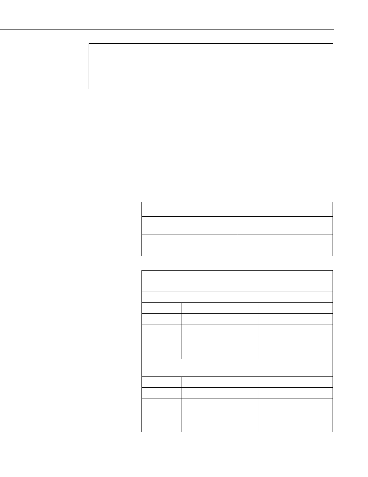
TABLE B-3. 14291 Field Power Cable Connections
TABLE B-4. 107 and SC110 Wiring for
⏚
⏚
⏚
If Daily.Output(1,1) Then
ROM_Cntr = 0
SR50A_WtchDg_Cntr = 0
EndIf
NextScan
B.3 RS-485 Example Programs
Detailed information using RS-232 and RS-485 is provided in Appendix D,
RS-232 and RS-485 Operation
B.3.1 CR1000 Programming Example Using an MD485 and
SC110 9-pin Male Connector
For this example, an MD485 is used to convert the SR50A RS-485 signals to
RS-232. A SC110 9-pin male connector cable is used to free up the RS-232
port on the datalogger.
MD485 is powered using a 14291 Field Power Cable.
Appendix B. Example Programs
(p. D-1).
CR1000 Datalogger or Directly
Field Power Cable Markings
Wire Marked (+)
Wire Marked (–)
to 12 Vdc Power Supply
12V
G
CR1000 RS-232 Example Program
107-L Air Temperature Sensor Wiring
Wire Color Sensor Wire Description CR1000 Wire Channels
Black Voltage-excitation input
Red Analog-voltage output
Purple Bridge resistor lead
Shield EMF shield
VX1
SE1
SC110 9-pin Male Connector Wiring
(9-pin connector plugged into MD485 RS-232 port)
Wire Color SC110 Wire Description CR1000 Wire Channels
Brown RX
C1
White TX
Yellow Ground
Shield Shield/Earth ground
C2
G
B-9
Page 42
Appendix B. Example Programs
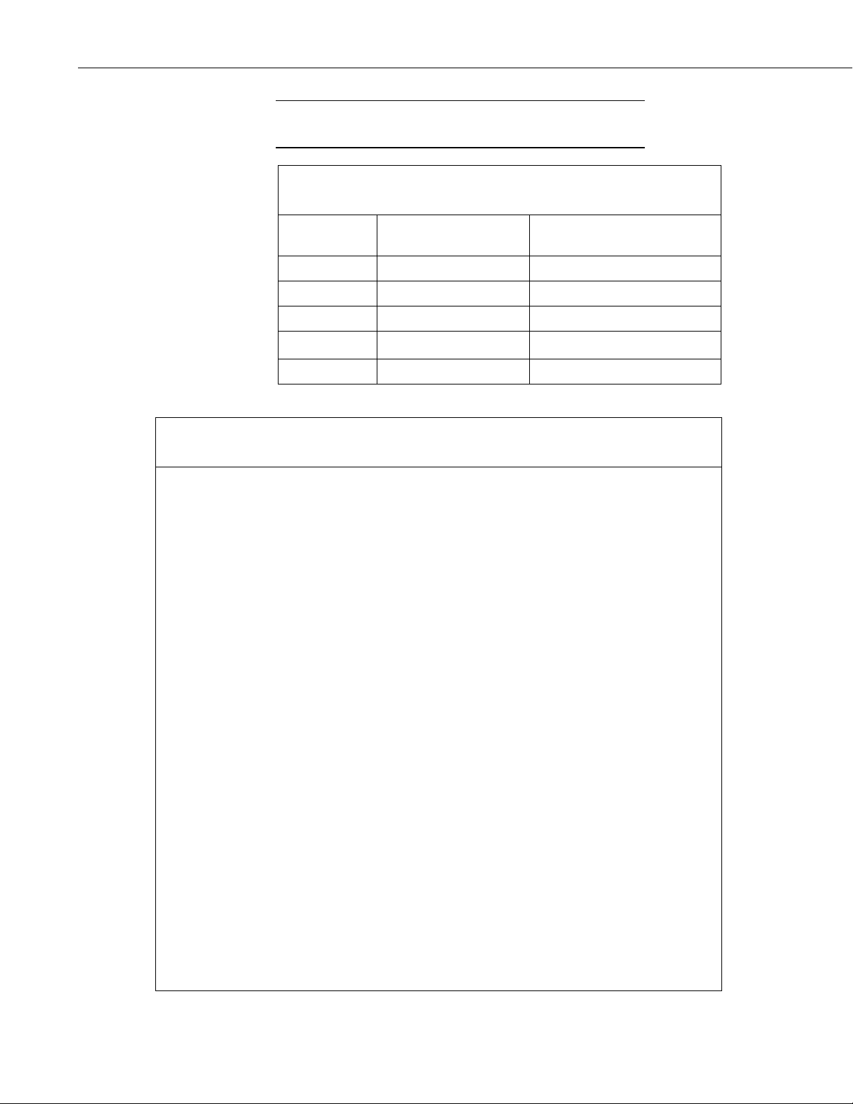
TABLE B-5. SR50A (Configured for MD485) Wiring to MD485
⏚
CRBasic Example B-4. CR1000 Programming Example Using an MD485 and SC110 9-pin
'CR1000 Series Datalogger
Public SR50ACtrl As Boolean
NOTE
Wire tie back all unused SC110 wires so they don’t short against
any metal.
(9-pin connector plugged into MD485 RS-232 port)
MD485 Wire Channel
Wire Color Wire Description
(except where indicated)
Red Power source CR1000 12V
Green A Any ‘A’ terminal
White B Any ‘B’ terminal
'Program: SR50A_RS485_Port_C1-C2.CR1
'This program contains a number of features not found in Short Cut.
'
'The initial distance value from the SR50A head to the ground is
'measured by setting the flag SR50A_MID to TRUE. Set this flag after
'installing the SR50A in the field. Setting this flag will initiate
'a measurement cycle and the resulting value stored as the initial
'distance. The initial distance is used to calculate snow depth.
'The PreserveVariables instruction is used to store the initial
'distance in non-volatile memory. If power is lost at the site the
'initial distance value will be restored.'
'A control flag is used to initiate the SR50A measurement cycle. This
'allows for manual control in the field to check distances without
'waiting for the correct time interval to occur. It is also used by
'the datalogger to initiate an automated measurement cycle.
'
'Every measurement cycle is composed of 11 individual measurements
'that are spatially sorted to eliminate any low or high values.
'One measurement is made with each scan. This program has a 10
'second scan rate so it will take 100 seconds to do all 11 scans or
'1 minute and 40 seconds.
'Declare Constants
'Default serial address of SR50A is 33. Polling command consists of
'a lower case 'p' followed by the address and a carriage return.
Const POLL_A = "p33" & CHR(13)
'Declare Variables and Units
Public BattV : Units BattV = Volts 'CR1000 battery voltage
Public PnlTmp_C : Units PnlTmp_C = °C 'CR1000 panel temperature
Public AirTempC : Units AirTempC = °C 'Air temperature
'Controls SR50A measurement. This flag can be manually controlled to
'run tests in the field or is automatically set 2 minutes before the
'hourly data storage interval. This is done so 11 measurements can
'be made and sorted before the values are stored.
Male Connector
Black Ground
Shield Shield/Earth ground CR1000 G
B-10
Page 43

Appendix B. Example Programs
ROM_Cntr += 1
'Set this flag to measure and store the initial distance from the
'SR50A to the ground.
Public SR50A_MID As Boolean
'Declare SR50AData as a dimensioned string of maximum 50 chrs
Public SR50AData As String * 50
'Values returned from the SR50A.
Public ParseVals(5) As Float
Alias ParseVals(1)=SerialAddress : Units SerialAddress = addr
Alias ParseVals(2)=Raw_Distance : Units Raw_Distance = meters
Alias ParseVals(3)=SignalQuality : Units SignalQuality = value
Alias ParseVals(4)=Diagnostics : Units Diagnostics = value
Alias ParseVals(5)=Chcksum : Units Chcksum = value
'Array to hold 11 SR50A measurements composed of a distance and
'quality number.
Public SR50A(11,2)
'Sorted array of 11 SR50A measurements composed of a distance and
'quality number. Measurements are sorted by the distance value from
'smallest to largest.
Public Result_SR50A(11,2)
Public TCDT : Units TCDT = meters 'Temperature corrected distance
Public Q : Units Q = unitless 'Quality number
Public Inital_Dist : Units Inital_Dist = meters 'Distance to ground.
Public Snow_Depth : Units Snow_Depth = meters 'Snow depth.
Dim n 'used as a counter
'SR50A diagnostic counters. Values are incremented if an error occurs.
Public ROM_Cntr : Units ROM_Cntr = value
Public SR50A_WtchDg_Cntr : Units SR50A_WtchDg_Cntr = value
Dim scratch
'Define Data Tables
DataTable(Daily,True,-1)
DataInterval(0,1440,Min,10)
Minimum(1,BattV,FP2,False,False)
Maximum (1,BattV,FP2,False,False)
Minimum(1,PnlTmp_C,FP2,False,False)
Maximum (1,PnlTmp_C,FP2,False,False)
Sample (1,ROM_Cntr,FP2)
Sample (1,SR50A_WtchDg_Cntr,FP2)
EndTable
DataTable (Hour,True,-1 )
DataInterval (0,60,Min,10)
Sample (1,AirTempC,FP2)
Sample (1,TCDT,IEEE4)
Sample (1,Q,FP2)
EndTable
PreserveVariables
'Subroutine to sum up errors from the SR50A across the day.
Sub Diag
scratch = INT(Diagnostics/1000)
Select Case scratch
Case 0
SR50A_WtchDg_Cntr += 1
ROM_Cntr += 1
Case 1
SR50A_WtchDg_Cntr += 1
Case 10
B-11
Page 44

EndSelect
Appendix B. Example Programs
EndSub
'Main Program
BeginProg
'Open and configure RS232 port for RS232 communication.
'9600 BAUD is the default:
SerialOpen (Com1,9600,0,0,200)
n = 1
Scan (10,Sec,3,0)
Battery (BattV)
PanelTemp (PnlTmp_C,_60Hz)
'Make an air temperature measurement.
Therm107 (AirTempC,1,1,Vx1,0,_60Hz,1.0,0)
'Automated snow depth measurement. Must occur two minutes before
'actual storage time to get 11 measurements completed.
If TimeIntoInterval (58,60,Min) Then
SR50ACtrl = True
EndIf
'Set this flag to true to get the initial distance from the SR50A
'to the ground.
If SR50A_MID Then SR50ACtrl = True
If SR50ACtrl Then
'Transmit serial command "p33<CR>"
SerialOut (Com1,POLL_A,"",0,0)
'Flush the serial buffer
SerialFlush (Com1)
'Recieve serial string from SR50A
SerialIn (SR50AData,Com1,200,CHR(13),50)
'Pars string into separate values.
SplitStr (ParseVals(),SR50AData,"",5,0)
'Calculate the temperature corrected distance.
SR50A(n,1) = ParseVals(2)*SQR((AirTempC+273.15)/273.15)
SR50A(n,2) = ParseVals(3)
n += 1
If n > 11 Then
n = 1
SR50ACtrl = False
SortSpa (Result_SR50A(1,1),11,SR50A(1,1),2)
TCDT = Result_SR50A(6,1)
Q = Result_SR50A(6,2)
If SR50A_MID Then
Inital_Dist = TCDT
SR50A_MID = False
EndIf
Snow_Depth = Inital_Dist - TCDT
EndIf
'Add up any errors across the day.
Call Diag
EndIf
'Call data tables.
CallTable Hour
CallTable Daily
'Clear diagnostic counters after Daily_Status table is stored.
If Daily.Output(1,1) Then
ROM_Cntr = 0
SR50A_WtchDg_Cntr = 0
EndIf
NextScan
EndProg
B-12
Page 45
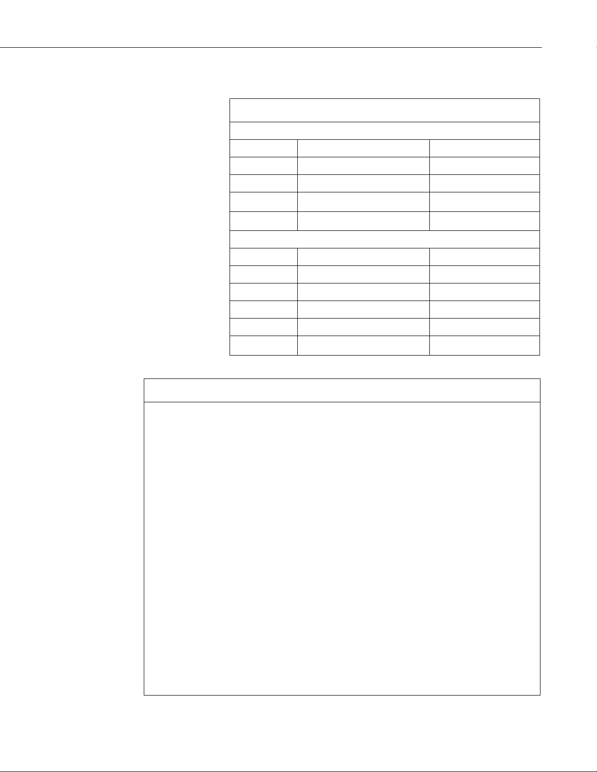
B.3.2 CR6 RS-485 Programming Example
TABLE B-6. Wiring for CR6 RS-485 Program
⏚
⏚
⏚
CRBasic Example B-5. CR6 RS-485 Programming Example
Public AirTempC : Units AirTempC = °C 'Air temperature
107-L Air Temperature Sensor Wiring
Wire Color Sensor Wire Description CR6 Wire Channels
Appendix B. Example Programs
Black Voltage-excitation input
Red Analog-voltage output
Purple Bridge resistor lead
Shield EMF shield
SR50A-L Configured for RS-232 Wiring
Wire Color Sensor Wire Description CR6 Wire Channels
Red Power source
Green A
White B
Black Ground
Shield Shield/Earth ground
'CR6 Series Datalogger
'This program contains a number of features not found in Short Cut.
'
'The initial distance value from the SR50A head to the ground is
'measured by setting the flag SR50A_MID to TRUE. Set this flag after
'installing the SR50A in the field. Setting this flag will initiate
'a measurement cycle and the resulting value stored as the initial
'distance. The initial distance is used to calculate snow depth.
'The PreserveVariables instruction is used to store the initial
'distance in non-volatile memory. If power is lost at the site the
'initial distance value will be restored.'
'A control flag is used to initiate the SR50A measurement cycle. This
'allows for manual control in the field to check distances without
'waiting for the correct time interval to occur. It is also used by
'the datalogger to initiate an automated measurement cycle.
'
'Every measurement cycle is composed of 11 individual measurements
'that are spatially sorted to eliminate any low or high values.
'One measurement is made with each scan. This program has a 10
'second scan rate so it will take 100 seconds to do all 11 scans or
'1 minute and 40 seconds.
'Declare Constants
'Default serial address of SR50A is 33. Polling command consists of
'a lower case 'p' followed by the address and a carriage return.
Const POLL_A = "p33" & CHR(13)
'Declare Variables and Units
Public BattV : Units BattV = Volts 'CR6 battery voltage
Public PnlTmp_C : Units PnlTmp_C = °C 'CR6 panel temperature
U2
U1
12V
C1
C2
G
B-13
Page 46

Appendix B. Example Programs
Case 0
'Controls SR50A measurement. This flag can be manually controlled to
'run tests in the field or is automatically set 2 minutes before the
'hourly data storage interval. This is done so 11 measurements can
'be made and sorted before the values are stored.
Public SR50ACtrl As Boolean
'Set this flag to measure and store the initial distance from the
'SR50A to the ground.
Public SR50A_MID As Boolean
'Declare SR50AData as a dimensioned string of maximum 50 chrs
Public SR50AData As String * 50
'Values returned from the SR50A.
Public ParseVals(5) As Float
Alias ParseVals(1)=SerialAddress : Units SerialAddress = addr
Alias ParseVals(2)=Raw_Distance : Units Raw_Distance = meters
Alias ParseVals(3)=SignalQuality : Units SignalQuality = value
Alias ParseVals(4)=Diagnostics : Units Diagnostics = value
Alias ParseVals(5)=Chcksum : Units Chcksum = value
'Array to hold 11 SR50A measurements composed of a distance and
'quality number.
Public SR50A(11,2)
'Sorted array of 11 SR50A measurements composed of a distance and
'quality number. Measurements are sorted by the distance value from
'smallest to largest.
Public Result_SR50A(11,2)
Public TCDT : Units TCDT = meters 'Temperature corrected distance
Public Q : Units Q = unitless 'Quality number
Public Inital_Dist : Units Inital_Dist = meters 'Distance to ground.
Public Snow_Depth : Units Snow_Depth = meters 'Snow depth.
Dim n 'used as a counter
'SR50A diagnostic counters. Values are incremented if an error occurs.
Public ROM_Cntr : Units ROM_Cntr = value
Public SR50A_WtchDg_Cntr : Units SR50A_WtchDg_Cntr = value
Dim scratch
'Define Data Tables
DataTable(Daily,True,-1)
DataInterval(0,1440,Min,10)
Minimum(1,BattV,FP2,False,False)
Maximum (1,BattV,FP2,False,False)
Minimum(1,PnlTmp_C,FP2,False,False)
Maximum (1,PnlTmp_C,FP2,False,False)
Sample (1,ROM_Cntr,FP2)
Sample (1,SR50A_WtchDg_Cntr,FP2)
EndTable
DataTable (Hour,True,-1 )
DataInterval (0,60,Min,10)
Sample (1,AirTempC,FP2)
Sample (1,TCDT,IEEE4)
Sample (1,Q,FP2)
EndTable
PreserveVariables
'Subroutine to sum up errors from the SR50A across the day.
Sub Diag
scratch = INT(Diagnostics/1000)
Select Case scratch
B-14
Page 47

SR50A_WtchDg_Cntr += 1
SR50A_WtchDg_Cntr = 0
Appendix B. Example Programs
ROM_Cntr += 1
Case 1
SR50A_WtchDg_Cntr += 1
Case 10
ROM_Cntr += 1
EndSelect
EndSub
'Main Program
BeginProg
'Open and configure C1 and C2 for RS485 communication.
'9600 BAUD is the default set at half-duplex:
SerialOpen (ComC1,9600,0,0,200,4)
n = 1
Scan (10,Sec,0,0)
Battery (BattV)
PanelTemp (PnlTmp_C,60)
'Make an air temperature measurement.
Therm107 (AirTempC,1,U1,U2,0,60,1.0,0)
'Automated snow depth measurement. Must occur two minutes before
'actual storage time to get 11 measurements completed.
If TimeIntoInterval (58,60,Min) Then
SR50ACtrl = True
EndIf
'Set this flag to true to get the initial distance from the SR50A
'to the ground.
If SR50A_MID Then SR50ACtrl = True
If SR50ACtrl Then
'Transmit serial command "p33<CR>"
SerialOut (ComC1,POLL_A,"",0,0)
'Flush the serial buffer
SerialFlush (ComC1)
'Recieve serial string from SR50A
SerialIn (SR50AData,ComC1,200,CHR(13),50)
'Pars string into separate values.
SplitStr (ParseVals(),SR50AData,"",5,0)
'Calculate the temperature corrected distance.
SR50A(n,1) = ParseVals(2)*SQR((AirTempC+273.15)/273.15)
SR50A(n,2) = ParseVals(3)
n += 1
If n > 11 Then
n = 1
SR50ACtrl = False
SortSpa (Result_SR50A(1,1),11,SR50A(1,1),2)
TCDT = Result_SR50A(6,1)
Q = Result_SR50A(6,2)
If SR50A_MID Then
Inital_Dist = TCDT
SR50A_MID = False
EndIf
Snow_Depth = Inital_Dist - TCDT
EndIf
'Add up any errors across the day.
Call Diag
EndIf
'Call data tables.
CallTable Hour
CallTable Daily
'Clear diagnostic counters after Daily_Status table is stored.
If Daily.Output(1,1) Then
ROM_Cntr = 0
B-15
Page 48
Appendix B. Example Programs
EndIf
EndProg
TABLE B-7. Wiring for CR1000 and CR6 Heater Example Programs
⏚ ⏚
⏚ ⏚
⏚ ⏚
CRBasic Example B-6. CR1000 Heater Program Example
'CR1000
'A control flag is used to initiate the SR50A measurement cycle. This
NextScan
B.4 Heater Program Examples
The following programs are written for a SR50AH-L configured for SDI-12.
Detailed information about the heater is provided in Appendix F, SR50AH
Heater Operation
107-L Air Temperature Sensor Wiring
Wire Color Sensor Wire Description CR1000 Wire Channels CR6 Wire Channels
(p. F-1).
Black Voltage-excitation input
Red Analog-voltage output
Purple Bridge resistor lead
Shield EMF shield
VX1 U2
SE1 U1
SR50A-L Configured for SDI-12 Wiring
Wire Color Sensor Wire Description CR1000 Wire Channels CR6 Wire Channels
Red Power source
Green SDI-12 I/O
White Not used
Black Ground
Shield Shield/Earth ground
12V 12V
C1 C1
G G
G G
G G
SR50AH Heater Power Cable
Wire Color Heater Wire Description CR1000 Wire Channels CR6 Wire Channels
Black Power source
White Power ground
Shield Shield/Earth ground
SW-12 SW12-1
G G
'This program contains a number of features not found in Short Cut.
'
'The initial distance value from the SR50A head to the ground is
'measured by setting the flag SR50A_MID to TRUE. Set this flag after
'installing the SR50A in the field. Setting this flag will initiate
'a measurement cycle and the resulting value stored as the initial
'distance. The initial distance is used to calculate snow depth.
'The PreserveVariables instruction is used to store the initial
'distance in non-volatile memory. If power is lost at the site the
'initial distance value will be restored.'
B-16
Page 49

'allows for manual control in the field to check distances without
'waiting for the correct time interval to occur. It is also used by
'Main Scan
'the datalogger to initiate an automated measurement cycle.
'
'Every measurement cycle is composed of 11 individual measurements
'that are spatially sorted to eliminate any low or high values.
'One measurement is made with each scan. This program has a 10
'second scan rate so it will take 100 seconds to do all 11 scans or
'1 minute and 40 seconds.
'Declare Variables and Units
Public BattV : Units BattV = Volts 'CR1000 battery voltage
Public PnlTmp_C : Units PnlTmp_C = °C 'CR1000 panel temperature
Public AirTempC : Units AirTempC = °C 'Air temperature
Public HtrCntrl As Boolean
Public SR50A_Raw(2)
Alias SR50A_Raw(1) = DT : Units DT = meters 'Distance from the SR50A.
Alias SR50A_Raw(2) = RawQ : Units RawQ = unitless 'Quality number.
'Array to hold 11 SR50A measurements composed of a distance and
'quality number.
Public SR50A(11,2)
'Sorted array of 11 SR50A measurements composed of a distance and
'quality number. Measurements are sorted by the distance value from
'smallest to largest.
Public Result_SR50A(11,2)
Public TCDT : Units TCDT = meters 'Temperature corrected distance
Public Q : Units Q = unitless 'Quality number
Public Inital_Dist : Units Inital_Dist = meters 'Distance to ground.
Public Snow_Depth : Units Snow_Depth = meters 'Snow depth.
'Controls SR50A measurement. This flag can be manually controlled to
'run tests in the field or is automatically set 2 minutes before the
'hourly data storage interval. This is done so 11 measurements can
'be made and sorted before the values are stored.
Public SR50ACtrl As Boolean
'Set this flag to measure and store the initial distance from the
'SR50A to the ground.
Public SR50A_MID As Boolean
Dim n 'used as a counter
'Define Data Tables
DataTable(Daily,True,-1)
DataInterval(0,1440,Min,10)
Minimum(1,BattV,FP2,False,False)
Maximum (1,BattV,FP2,False,False)
Minimum(1,PnlTmp_C,FP2,False,False)
Maximum (1,PnlTmp_C,FP2,False,False)
EndTable
DataTable (Hour,True,-1 )
DataInterval (0,60,Min,10)
Sample (1,AirTempC,FP2)
Sample (1,TCDT,IEEE4)
Sample (1,Q,FP2)
EndTable
PreserveVariables
'Main Program
BeginProg
Appendix B. Example Programs
B-17
Page 50

n = 1
EndProg
Appendix B. Example Programs
Scan(10,Sec,1,0)
'Battery Voltage measurement 'BattV'
Battery(BattV)
'Wiring Panel Temperature measurement 'PnlTmp_C'
PanelTemp(PnlTmp_C,_60Hz)
'107 Temperature Probe measurement 'AirTempC'
Therm107(AirTempC,1,1,1,0,_60Hz,1,0)
'Automated snow depth measurement. Must occur two minutes before
'actual storage time to get 11 measurements completed.
If TimeIntoInterval (58,60,Min) Then
SR50ACtrl = True
EndIf
'Set this flag to true to get the initial distance from the SR50A
'to the ground.
If SR50A_MID Then SR50ACtrl = True
'Logic to make 11 snow depth measurements, sort them, and store
'the corrected values.
If SR50ACtrl Then
'SR50A Sonic Ranging Sensor (SDI-12 Output) measurements
'DT' & 'Q'
SDI12Recorder(SR50A_Raw(),1,"0","M1!",1,0)
'Calculate the temperature corrected distance.
SR50A(n,1) = SR50A_Raw(1)*SQR((AirTempC+273.15)/273.15)
SR50A(n,2) = SR50A_Raw(2)
n += 1
If n > 11 Then
n = 1
SR50ACtrl = False
SortSpa (Result_SR50A(1,1),11,SR50A(1,1),2)
TCDT = Result_SR50A(6,1)
Q = Result_SR50A(6,2)
If SR50A_MID Then
Inital_Dist = TCDT
SR50A_MID = False
EndIf
Snow_Depth = Inital_Dist - TCDT
EndIf
EndIf
'SR50A Heater Control
If BattV >= 11.7 Then
If AirTempC <= 2 Then HtrCntrl = True
If AirTempC > 3 Then HtrCntrl = False
Else
HtrCntrl = False
EndIf
SW12(HtrCntrl)
'Call Data Tables and Store Data
CallTable Daily
CallTable Hour
NextScan
B-18
Page 51

CRBasic Example B-7. CR6 Heater Program Example
'CR6
Minimum(1,PnlTmp_C,FP2,False,False)
Appendix B. Example Programs
'This program contains a number of features not found in Short Cut.
'
'The initial distance value from the SR50A head to the ground is
'measured by setting the flag SR50A_MID to TRUE. Set this flag after
'installing the SR50A in the field. Setting this flag will initiate
'a measurement cycle and the resulting value stored as the initial
'distance. The initial distance is used to calculate snow depth.
'The PreserveVariables instruction is used to store the initial
'distance in non-volatile memory. If power is lost at the site the
'initial distance value will be restored.'
'A control flag is used to initiate the SR50A measurement cycle. This
'allows for manual control in the field to check distances without
'waiting for the correct time interval to occur. It is also used by
'the datalogger to initiate an automated measurement cycle.
'
'Every measurement cycle is composed of 11 individual measurements
'that are spatially sorted to eliminate any low or high values.
'One measurement is made with each scan. This program has a 10
'second scan rate so it will take 100 seconds to do all 11 scans or
'1 minute and 40 seconds.
'Declare Variables and Units
Public BattV : Units BattV = Volts 'CR6 battery voltage
Public PnlTmp_C : Units PnlTmp_C = °C 'CR6 panel temperature
Public AirTempC : Units AirTempC = °C 'Air temperature
Public HtrCntrl As Boolean
'Array to hold 11 SR50A measurements composed of a distance and
'quality number.
Public SR50A(11,2)
Public SR50A_Raw(2)
Alias SR50A_Raw(1) = DT : Units DT = meters 'Distance from the SR50A.
Alias SR50A_Raw(2) = RawQ : Units RawQ = unitless 'Quality number.
'Sorted array of 11 SR50A measurements composed of a distance and
'quality number. Measurements are sorted by the distance value from
'smallest to largest.
Public Result_SR50A(11,2)
Public TCDT : Units TCDT = meters 'Temperature corrected distance
Public Q : Units Q = unitless 'Quality number
Public Inital_Dist : Units Inital_Dist = meters 'Distance to ground.
Public Snow_Depth : Units Snow_Depth = meters 'Snow depth.
'Controls SR50A measurement. This flag can be manually controlled to
'run tests in the field or is automatically set 2 minutes before the
'hourly data storage interval. This is done so 11 measurements can
'be made and sorted before the values are stored.
Public SR50ACtrl As Boolean
'Set this flag to measure and store the initial distance from the
'SR50A to the ground.
Public SR50A_MID As Boolean
Dim n 'used as a counter
'Define Data Tables
DataTable(Daily,True,-1)
DataInterval(0,1440,Min,10)
Minimum(1,BattV,FP2,False,False)
Maximum (1,BattV,FP2,False,False)
B-19
Page 52

Appendix B. Example Programs
Maximum (1,PnlTmp_C,FP2,False,False)
'Call Data Tables and Store Data
EndTable
DataTable (Hour,True,-1 )
DataInterval (0,60,Min,10)
Sample (1,AirTempC,FP2)
Sample (1,TCDT,IEEE4)
Sample (1,Q,FP2)
EndTable
PreserveVariables
'Main Program
BeginProg
'Main Scan
n = 1
Scan(10,Sec,1,0)
'Battery Voltage measurement 'BattV'
Battery(BattV)
'Wiring Panel Temperature measurement 'PnlTmp_C'
PanelTemp(PnlTmp_C,60)
'107 Temperature Probe measurement 'AirTempC'
Therm107(AirTempC,1,U1,U2,0,60,1,0)
'Automated snow depth measurement. Must occur two minutes before
'actual storage time to get 11 measurements completed.
If TimeIntoInterval (13,15,Min) Then
SR50ACtrl = True
EndIf
'Set this flag to true to get the initial distance from the SR50A
'to the ground.
If SR50A_MID Then SR50ACtrl = True
'Logic to make 11 snow depth measurements, sort them, and store
'the corrected values.
If SR50ACtrl Then
'SR50A Sonic Ranging Sensor (SDI-12 Output) measurements
'DT' & 'Q'
SDI12Recorder(SR50A_Raw(),C1,"0","M1!",1,0)
'Calculate the temperature corrected distance.
SR50A(n,1) = SR50A_Raw(1)*SQR((AirTempC+273.15)/273.15)
SR50A(n,2) = SR50A_Raw(2)
n += 1
If n > 11 Then
n = 1
SR50ACtrl = False
SortSpa (Result_SR50A(1,1),11,SR50A(1,1),2)
TCDT = Result_SR50A(6,1)
Q = Result_SR50A(6,2)
If SR50A_MID Then
Inital_Dist = TCDT
SR50A_MID = False
EndIf
Snow_Depth = Inital_Dist - TCDT
EndIf
EndIf
'SR50A Heater Control
If BattV >= 11.7 Then
If AirTempC <= 2 Then HtrCntrl = True
If AirTempC > 3 Then HtrCntrl = False
Else
HtrCntrl = False
EndIf
SW12(1,HtrCntrl,1)
B-20
Page 53

CallTable Daily
CallTable Hour
EndProg
NextScan
Appendix B. Example Programs
B-21
Page 54

Appendix B. Example Programs
B-22
Page 55
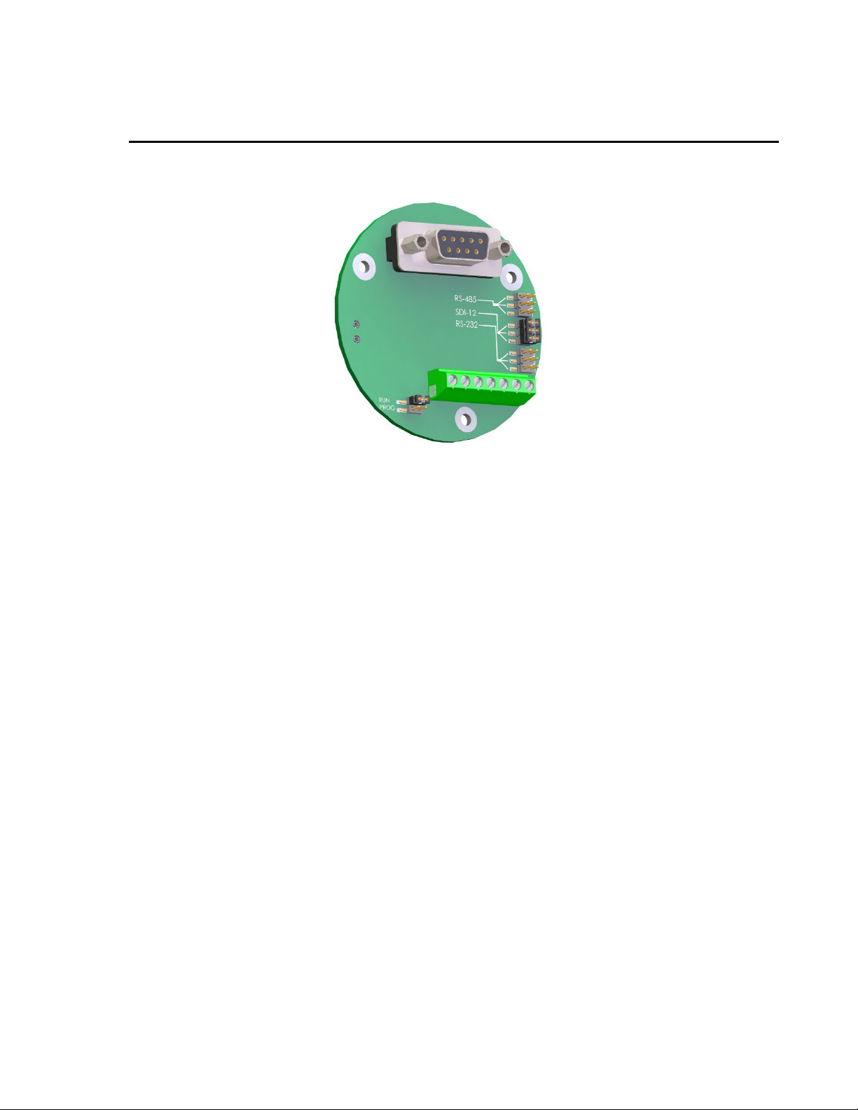
Appendix C. Jumper Settings
FIGURE C-1 shows the jumper locations of the SR50A.
FIGURE C-1. Jumper Settings
The SR50A can be configured with either SDI-12, RS-232 or RS-485
communications. Shunt jumpers can be located on any of the three sets of
communication selection headers. Only place the three jumpers on one group at
a time. Never install more than three jumpers and never mix the jumpers
among the SDI-12, RS-232 or RS-485 locations.
The other jumper located on the SR50A places the sensor in either the normal
operation mode or in the program update mode. The program mode is only
used for updating the internal firmware of the sensor. During operation, have
the jumper in the RUN position.
Refer to Appendix E.2, Sending New Firmware to a SR50A/T Sensor for details
about SR50A
firmware updates.
C-1
Page 56

Page 57
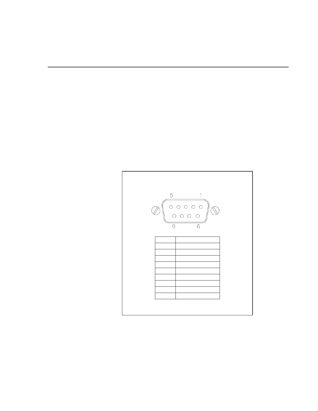
RS-232 Female DB9 Connector with Terminal Blocks
Pin
Assignment
1
DCD
2
RXD
3
TXD
4
DTR
5
GND
6
DSR
7
RTS
8
CTS 9 N/A
Appendix D. RS-232 and RS-485 Operation
D.1 RS-232 Operation
The SR50A sensor comes from the factory with the internal jumpers set to
SDI-12 mode. To use the SR50A in the RS-232 mode of operation, the jumpers
need to be set as outlined in Appendix C, Jumper Settings
RS-232 CRBasic programs can be found in Appendix B.2, RS-232 Example
Programs
D.1.1 RS-232 Wiring
FIGURE D-1 and TABLE D-1 show wiring for the SR50A in RS-232 mode.
The ground used with the RS-232 connector (pin 5) must use the same ground
as the SR50A. For the example below, the power for the SR50A is coming
from the datalogger. A jumper wire is used from the RS-232 connector’s pin 5
to the datalogger ground.
(p. B-6).
(p. C-1). Complete
(Campbell Scientific pn 28840)
Pins used for RS-232 communication in bold lettering.
FIGURE D-1. RS-232 DB9 Connector Description
D-1
Page 58
Appendix D. RS-232 and RS-485 Operation
TABLE D-1. SR50A RS-232 Interface Wiring
TABLE D-2. SR50A Datalogger COM Port Wiring
SR50A Wire
Color
Red +12 Vdc Power Power Source (Datalogger: 12V)
Black Power Ground
Green
White
Clear Shield G (datalogger)
Jumper Wire
SR50A Wire
Color
Red +12 Vdc Power
Black Power Ground
(SR50A Output)
Function
RS-232
RS-232
(SR50A Input)
Function
Wiring Location
System Ground and/or RS-232
Receiver Ground (Datalogger: G)
Pin 2 [RXD] (9-pin RS-232 Interface
Connector: pn 28840)
Pin 3 [TXD] (9-pin RS-232 Interface
Connector: pn 28840)
Pin 5 [G] (9-pin RS-232 Interface
Connector: pn 28840)
CR1000
12V 12V
G G
CR6
Green
White
Clear Shield
D.2 RS-485 Operation
The SR50A sensor comes from the factory with the internal jumpers set to
SDI-12 mode. To use the SR50A in the RS-485 mode of operation, the jumpers
need to be set as outlined in Appendix C, Jumper Settings
RS-485 CRBasic programs can be found in Appendix B.3, RS-485 Example
Programs
The RS-485 on the SR50A supports half-duplex communications, which means
the SR50A can receive and transmit data, but not simultaneously. Normally a
master-slave relationship is used in most systems to avoid collisions between
transmissions. For this reason, the Auto Measure Output is not recommended
for RS-485 communications. It is much better to have a master initiate the
communications by using the Measure On Poll or the Auto Measure Polled
Output modes.
You can use Campbell Scientific’s MD485 interface to connect one or more
SR50A sensors in RS-485 mode to an RS-232 device. This can be useful for
(p. B-9).
RS-232
(SR50A Output)
RS-232
(SR50A Input)
RX (COM1–
COM4)
TX (COM1–
COM4)
G G
RX (COM1–
COM2)
TX (COM1–
COM2)
(p. C-1). Complete
D-2
Page 59
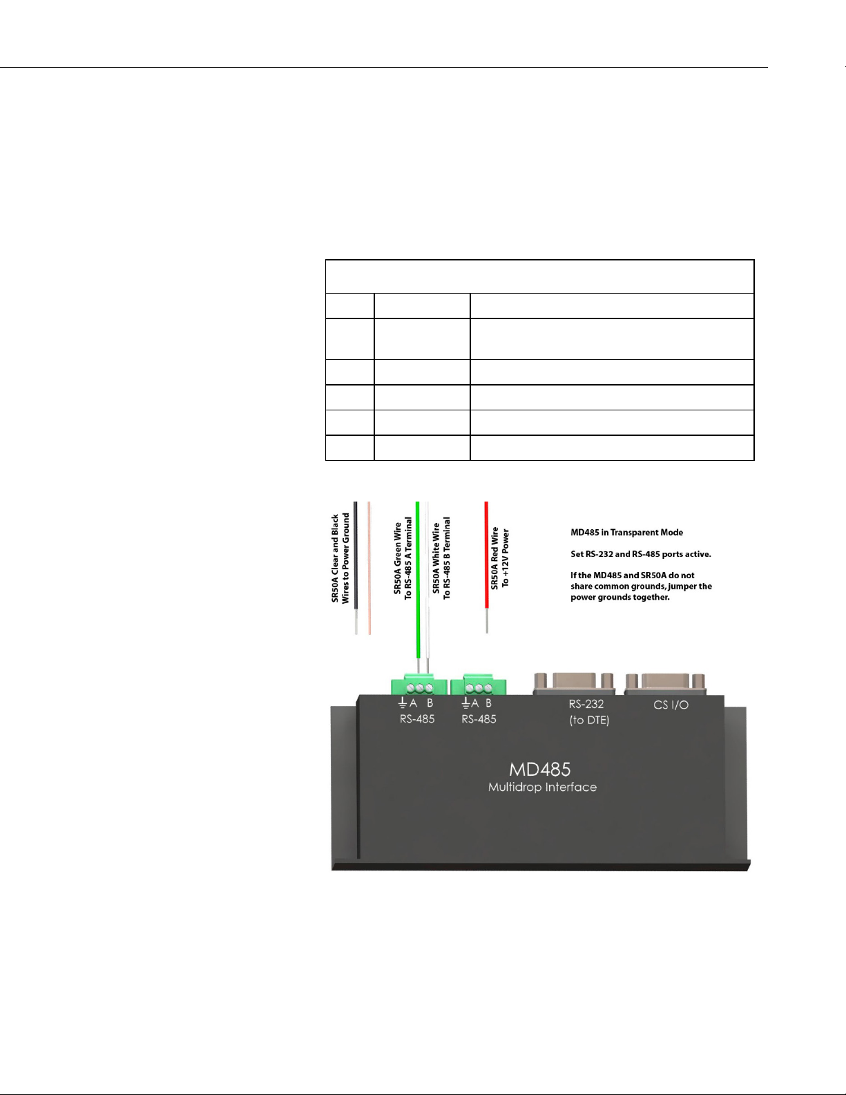
Appendix D. RS-232 and RS-485 Operation
TABLE D-3. Connections for RS-485 Mode
sensors that require lead lengths that exceed the limits of either RS-232 or
SDI-12 communications.
The SR50A can be connected directly the RS-485 port on the CR6 datalogger.
D.2.1 RS-485 Wiring Using a MD485
TABLE D-3 and FIGURE D-2 show the wiring for the SR50A in RS-485
mode.
Color Function Connection
Black Power Ground System Ground and/or RS-232 Receiver Ground
(Pin 5 of a computer (DTE) DB-9 connector)
Red Power Power Source +12V
Green RS-485 A MD485 RS-485 A Terminal
White RS-485 B MD485 RS-485 B Terminal
Clear Shield Shield/Earth Ground
FIGURE D-2. SR50A to MD485 Wiring
D-3
Page 60
Appendix D. RS-232 and RS-485 Operation
TABLE D-4. Connections for CR6 RS-485 Mode
NOTE
D.3 RS-485 Wiring to a CR6 Datalogger
The SR50A is a half-duplex device and can only be used on the COM1 (C1
and C2) terminal blocks.
Color Function Connection
Black Power Ground
Red Power
Green RS-485 A
White RS-485 B
Clear Shield
D.4 RS-232 and RS-485 Settings
Once the jumpers are set for RS-232 operation, a terminal program such as
Device Configuration Utility or Tera Term can be used to change factory
defaults or existing settings. Use a terminal program that allows local echo.
The SR50A does not echo key presses. To see what is being typed, Local Echo
must be switched on. A quick introduction to Tera Term is located in Appendix
E, Tera Term QuickStart
Configuration Utility or any program used for communications.
Baud Rate: Current SR50A Setting
Data Bits: 8
Parity: None
Stop Bits: 1
Flow Control: None
Local Echo: On
(p. E-1). The following settings apply to Device
12V
Note
G
C1
C2
G
The factory default baud rate is 9600 bps. Once the baud rate is
changed, the new baud rate must be used for further
communications to the SR50A. Ensure to keep track of the baud
rate setting on the SR50A. If the baud rate setting is unknown, try
using the default value of 9600 bps. If that does not work, start the
baud rate at 1200 bps and go through all the baud rate settings until
the correct one is found.
Select the following when using Device Configuration Utility (FIGURE D-3).
D-4
• Device Type: Unknown
• Choose the correct COM port.
• By default, the baud rate in the SR50A and Device Configuration
Utility is set to 9,600. Only change the baud rate if you know it has
been changed in the SR50A.
• Click on the Connect button in the lower left hand corner.
Page 61
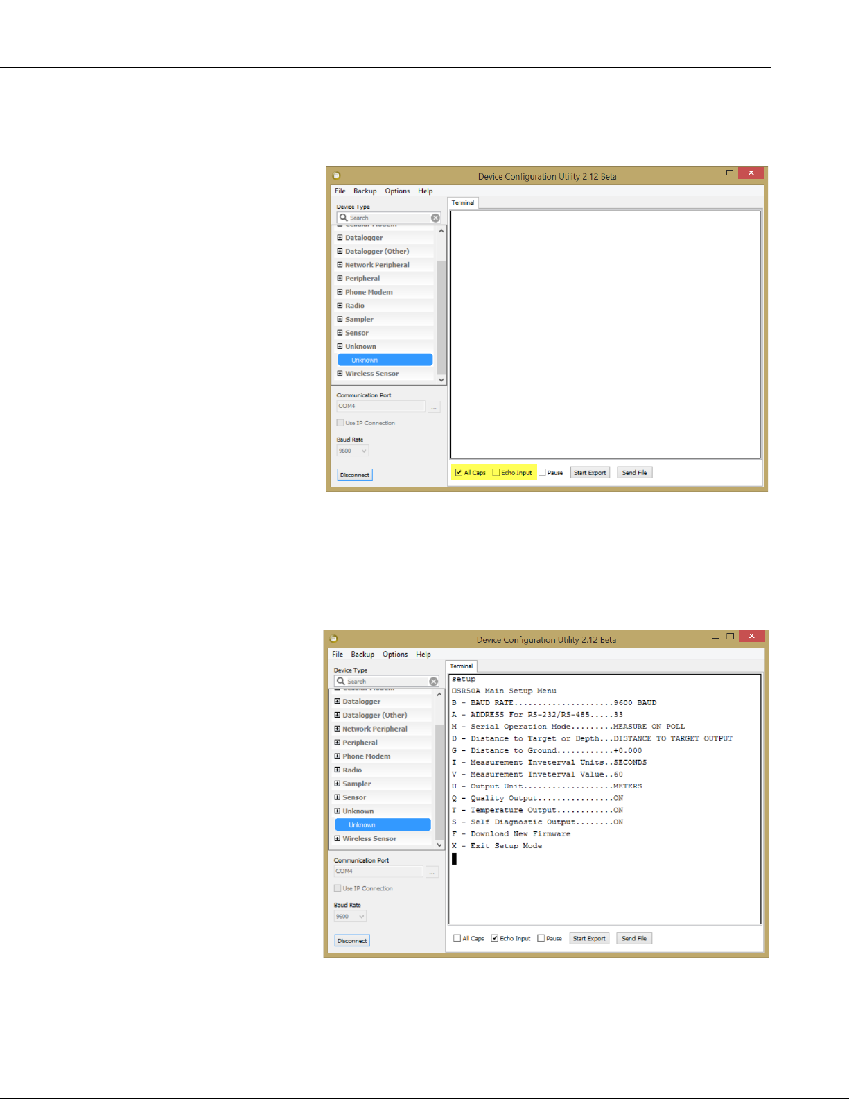
Appendix D. RS-232 and RS-485 Operation
• Uncheck the All Caps box.
• Check the Echo Input box.
FIGURE D-3. Initial Terminal Window in Device Configuration Utility
To enter Setup mode, type “setup” in the terminal window and press the Enter
key. The word “setup” and all options in the setup menu are not case sensitive.
The SR50A should respond with the setup menu shown in FIGURE D-4.
FIGURE D-4. SR50A Setup Menu
D-5
Page 62

Appendix D. RS-232 and RS-485 Operation
TABLE D-5. RS-232 and RS-485 Settings
TABLE D-5 summarizes the settings that can be changed using the SR50A
RS-232 or RS-485 operating modes. Recommended changes are shown in
parenthesis.
Setting Description Options Default Value
1200
4800
Baud Rate
Address RS-232/RS-485 Any two Alphanumeric Characters 33
9600
19200
38400
9600 bps
Measure on Poll
Serial Operational Mode
Distance to Target or
Depth output
Distance to Ground Decimal Value in Meters 0.0
Measurement Interval Units
Measurement Interval Value Integer 1-255 60
Output Unit
Setting Description Options Default Value
Quality Output
Temperature Output
Diagnostics Output
Auto Measure Auto Output
Auto Measure Polled Output
Distance to Target
Depth
Seconds
Minutes
Hours
Meters
Centimeters
Millimeters
Feet
Inches
On
Off
On
Off
On
Off
Auto Measure Auto Output
(Change this to Measure on Poll.)
Distance to Target
Seconds
Meters
Off
(Change this to ON.)
Off
Output valid only for the SR50AT
Off
(Change this to ON.)
D-6
D.4.1 Baud Rate Setting
The factory default baud rate setting of 9600 bps is suitable for most
applications. Lower baud rates (1200 or 4800 bps) may improve
communication reliability or allow for longer cable lengths. Higher baud rates
(19200 or 38400 bps) may be used where faster communications are required.
The quiescent current draw for the SR50A in serial mode is normally 1.25 mA
for baud rates of 9600 or less. The current draw increases to 1.5 and 2.25 mA
for the baud rates of 19200 or 38400 bps, respectively.
Page 63

It is possible to download a firmware update to the SR50A via the RS-232 or
RS-485 communication interface. Higher baud rates may be desirable to speed
up this process.
It may take up to 30 minutes using a speed of 1200 bps, 7 minutes using 9600
bps, or 3 minutes using 38400 bps.
D.4.2 Address
The factory default address is 33. For RS-232 applications, use the factory
default address. For RS-485 operation, multiple sensors can be polled
individually if different addresses are assigned.
D.4.3 Operational Mode Setting
Three different operational mode settings are available on the SR50A. Overall
system design and desired performance determine which mode to select. The
SR50A operation for each of the three different modes are described below as
well as the advantages and disadvantages of each mode.
D.3.3.1 Measure in Poll Mode
In this mode, the SR50A remains idle until a measurement command is sent
(p33<CR>) where 33 is the default serial address. After receiving the
measurement command, the SR50A immediately begins a measurement and
transmits the resulting data packet when the measurement is complete.
Typically, the SR50A transmits the data packet within 1 second of receiving
the command packet.
Appendix D. RS-232 and RS-485 Operation
• The SR50A only performs a measurement when requested.
• The data output will lag the measurement command by 1 second.
• This configuration is conducive to a multidrop RS-485 system where
individual sensors do not transmit data until they are addressed.
D.3.3.2 Auto Measure Auto Output Mode
In this mode, the SR50A automatically exits its low power mode, initiates a
measurement, and outputs the data. The frequency that the SR50A performs
these functions is set by adjusting the Measurement Interval Units and the
Measurement Interval Value parameters.
• No command is required from an external device to obtain a measurement.
• The data recorder or equipment simply needs to read the incoming serial
data from the SR50A.
D.3.3.3 Auto Measure Polled Output Mode
In this mode, the SR50A automatically exits its low power mode and initiates a
measurement. The output data string is not sent until a poll command is
received. When a poll command is received by the SR50A, the output data
typically commences 100 ms after the poll command is sent.
D-7
Page 64

Appendix D. RS-232 and RS-485 Operation
The frequency that the SR50A performs the measurement is set by adjusting
the Measurement Interval Units and the Measurement Interval Value
parameters.
• The main advantage of this operating mode is that the receiving device
will only have to wait 100 ms for the data instead of 1 second.
• This configuration is also more conducive to a multidrop RS-485 system
where individual sensors do not transmit until they are addressed.
D.4.4 Distance to Target or Depth
The SR50A can output either distance to target values or calculate snow depth
values. To obtain a valid snow depth value the parameter distance to ground
must be entered in.
The SR50AT will compensate the readings for temperature.
Do not use this option on the SR50A sensor unless the SR50A is sent valid
temperature reading via the Temperature Input command.
D.4.5 Distance to Ground
A valid distance to ground must be entered when the SR50A is configured to
output snow depth values. The value must be in meters regardless of the output
units that are selected.
If the exact value cannot be obtained, it is better to slightly overestimate the
value rather than underestimating it. If a Distance to Ground value is too
small, the SR50A will output an error value as the snow surface should not be
below the ground surface.
D.4.6 Measurement Interval Units
This setting is only applicable if either the Auto Measure Polled Output or the
Auto Measure Auto Output modes are used. The options for the Measurement
Interval Units are:
• Seconds
• Minutes
• Hours
Once a unit type is selected, the number of units for the interval is set by
changing the Measurement Interval Value parameter. A 60 s interval can be
set by setting the units to seconds and the Measurement Interval Value to 60.
Alternately, the Measurement Interval Unit could be set to minutes and the
Value could be set to 1. The Value setting can only range from 1 to 255.
D-8
D.4.7 Measurement Interval Value
This setting is only applicable if either the Auto Measure Polled Output or the
Auto Measure Auto Output modes are used. The Measurement Interval Value
can range from 1 to 255. The units used for the value is set by the
Measurement Interval Units.
Page 65

D.4.8 Output Unit
The SR50A always outputs the distance to the target. The units for the distance
value can be set to any of the following values:
• Meters
• Centimeters
• Millimeters
• Feet
• Inches
D.4.9 Quality Output
The SR50A quality numbers can be optionally included in the data output
string. The Quality Output setting can be set to ON or OFF.
D.4.10 Diagnostics Output
The SR50A diagnostics numbers can be optionally included in the data output
string. The Diagnostics Output setting can be set to ON or OFF.
D.5 Serial Commands
Appendix D. RS-232 and RS-485 Operation
D.5.1 Setup Command
The setup command places the SR50A in the serial setup mode. This command
should only be sent to customize a sensor’s settings. Upper and lower case
letters are accepted and a carriage return character must also terminate the
string.
“setup<CR>”
D.5.2 Poll Command
The poll command is used to obtain the sensor’s output values. The poll
command consists of the upper or lower case letter “p” followed by the SR50A
address (default 33). The command must also terminate with a carriage return
character.
“pAA<CR>” – where AA is a two-character address and set from the
factory to 33
“p33<CR>” – Poll command with factory address of 33
D.5.3 Information Command
The information command is used to query information from the sensor that is
not associated with the sensor’s output. For detailed information on the output
refer to Section 9.2.1, Data Interpretation
(p. 18).
The information command consists of the upper or lower case letter “i”
followed by the SR50A address (default 33). The command must also
terminate with a carriage return character.
D-9
Page 66

Appendix D. RS-232 and RS-485 Operation
“iAA<CR>” – where AA is a two-character address and set from the
factory to 33
“i33<CR>” – information command with factory address of 33
D.5.4 Temperature Input Command
The temperature input command is used to send the SR50A version of the
sensor a temperature value that is to be used for temperature compensation.
The value sent must be in degrees Celsius and should not exceed eight
characters.
The command consists of the upper or lower case letter “t” followed by the
SR50A address (default 33) a semicolon and the temperature value. The
command must also terminate with a carriage return character (Enter for
Hyperterminal).
“tAA;-5.5<CR>” – where AA is a two-character address and set from the
factory to 33 and –5.5 is the temperature in degrees C
“t33;tt.ttt<CR>” – Temperature command with factory address of 33 and
a temperature value in Celsius.
D.6 RS-232/RS-485 Data Output Format
D.6.1 Measurement Output
The measurement output string for the SR50A is as follows:
<STX>aa;D.DDD;QQQ;TT.TT;VVVVV;CC<CR><LF><ETX>
<STX> is the hex character &h02 (2 in decimal)
aa
These two characters are the serial address of the sensor. The default is 33.
Note this is two ASCII characters of &h33 in hexidecimal or 51 in decimal.
D.DDD
This is the distance to target reading. The units depend on the Output Units
setting. The number of digits and decimal places also depend on the output unit
that is selected. The decimal digits are as follows:
Meters: D.DDD, 0.000 for no valid reading
DD.DDD possible for values past 9.999 m
Centimeters: DDD.DD
DDDD.DD possible for values past 999.99 cm
000.00 output for no valid reading
D-10
Millimeters: DDDD
-999 output for no valid reading
9999 Maximum value
Feet: DD.DDD
00.000 output for no valid reading
Page 67

Appendix D. RS-232 and RS-485 Operation
Inches: DDD.DD
000.00 output for no valid reading
QQQ
This data value is the optional quality value output. The quality value is always
a three-digit integer and varies from 152 to 600, where 600 is the poorest
quality.
TT.TT
This setting must be set to Off. The SR50A will output a –999.00 if the
Temperature Output option is set to ON.
VVVVV
This is the diagnostic output value. Each digit represents a pass or a fail on a
diagnostic test.
XVVVV
If X is a 1, then the ROM Memory has passed the signature test.
VXVVV
If X is a 1, then no watchdog errors have occurred.
VVXXX
The three digits XXX are for factory use and should always read 111.
CC
This is a two-character checksum of the data packet. The checksum is the two’s
complement of the data packet sum including control characters.
The Least significant byte is used resulting in a two-character checksum.
<STX> = &h02 (Hexadecimal)
<CR> = &h0D (Hexadecimal)
<LF> = &h0A (Hexadecimal)
<ETX> = &h03 (Hexadecimal)
The following is a sample packet with proper checksum:
<STX>33;1838;194;11011;2C<CR><LF><ETX>
SUM =
02+33+33+3B+31+38+33+38+3B+31+39+34+3B+31+31+30+31+31
+3B+0D+0A+03
=0x3D4
Use Last byte only (D4) and calculate two’s complement = 100 – D4 = 2C
<CR>
Carriage return character. 0x0d in hexadecimal or 13 in decimal
<LF>
Line feed character. 0x0a in hexadecimal or 10 in decimal
<ETX>
End of transmission character. 0x03 in hexadecimal or 3 in decimal
D-11
Page 68

Appendix D. RS-232 and RS-485 Operation
D.6.2 Information Message Output
The measurement output string for the SR50A is as follows:
<STX>aa;SSSSS;H.H;F.F;BBBBB;WWWWW<CR><LF><ETX>
<STX> is the hex character 0x02 (2 in decimal)
aa
These two characters are the serial address of the sensor. The default is 33.
Note this is two ASCII characters of 0x33 in hexidecimal or 51 in decimal.
SSSSS
This is the serial number of the sensor.
H.H
This is the hardware version of the sensor.
F.F
This is the firmware version of the sensor.
BBBBB
This is the checksum of the boot code.
WWWWW
This is the checksum of the firmware.
CC
This is a two-character checksum of the data packet. The checksum is the two’s
complement of the data packet sum including control characters.
The least significant byte is used resulting in a two-character checksum.
<STX> = &h02 (hexadecimal)
<CR> = &h0D (hexadecimal)
<LF> = &h0A (hexadecimal)
<ETX> = &h03 (hexadecimal)
The following is a sample packet with proper checksum:
<STX>33;1838;194;11011;2C<CR><LF><ETX>
SUM =
02+33+33+3B+31+38+33+38+3B+31+39+34+3B+31+31+30+31+31
+3B+0D+0A+03
=0x3D4
Use Last byte only (D4) and calculate two’s complement = 100 – D4 = 2C
<CR>
Carriage return character. &h0D in hexadecimal or 13 in decimal
D-12
<LF>
Line feed character. &h0A in hexadecimal or 10 in decimal
<ETX>
End of transmission character. &h03 in hexadecimal or 3 in decimal
Page 69
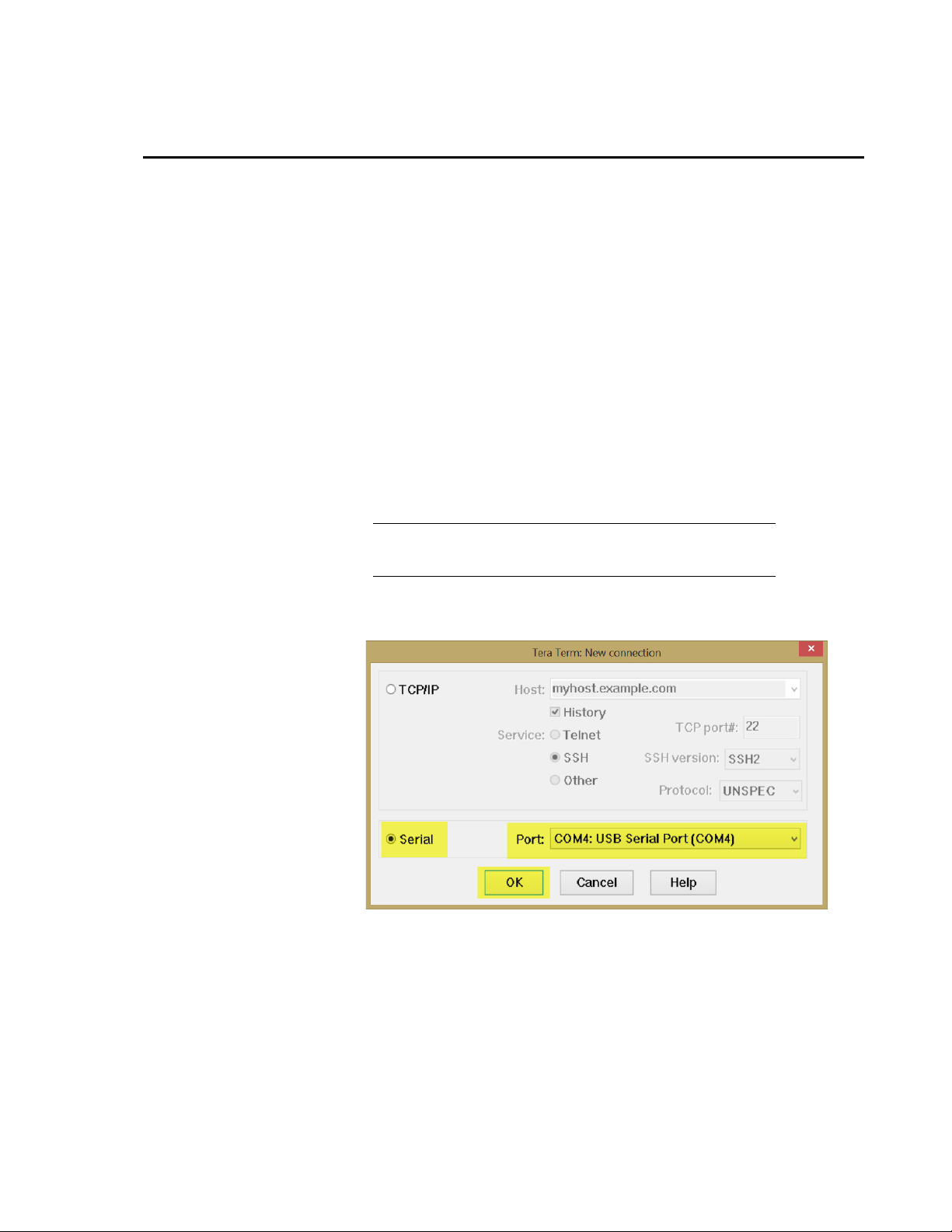
NOTE
Appendix E. Tera Term QuickStart
Tera Term can be used to configure the RS-232 or RS-485 settings or to update
the sensor’s firmware. Tera Term is a powerful open-source terminal emulation
package. It can be accessed from the link below. Pull down and install the
latest version.
https://en.osdn.jp/projects/ttssh2/releases/
E.1 Configure Tera Term for Serial 9600 BPS
Communication
1. Click on the Tera Term icon and bring up the software. Tera Term always
starts up with the New connection window as shown in FIGURE E-1.
a. Click on the radio button next to Serial.
b. Click on the down arrow to the far right of Port and pick the COM
port you are using to communication with the SR50A/T.
COM port 4 is used in the examples in this section. Your COM
port may be different.
c. Click on the OK button.
FIGURE E-1. Tera Term New Connection
E-1
Page 70
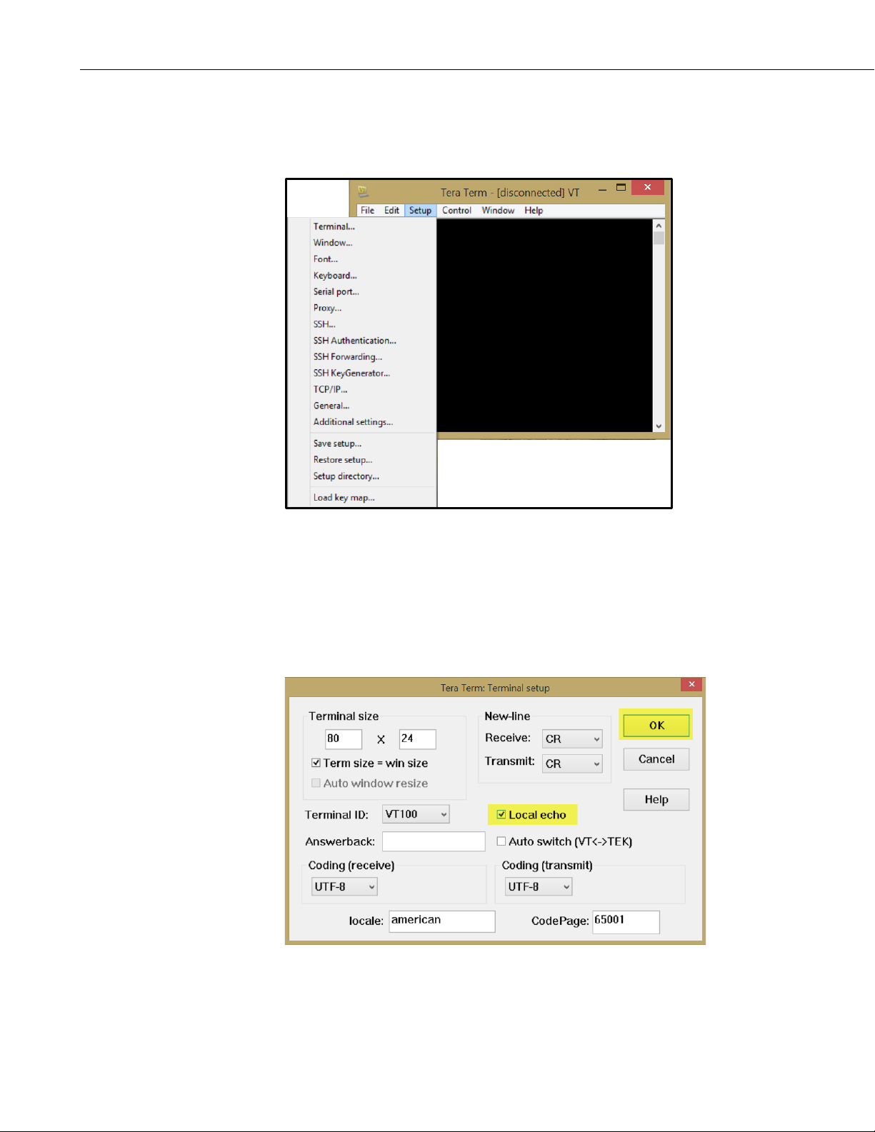
Appendix E. Tera Term QuickStart
2. FIGURE E-2 shows the standard Tera Term working screen and the pull-
down menu for Setup. To see this screen, click on Setup at the top of the
screen.
FIGURE E-2. Setup Selections
3. Select Terminal from the drop-down menu list in Setup. The SR50A/T
does not echo characters sent to it. To see what you’re typing, Local Echo
needs to be switched on by checking the box next to Local Echo
(FIGURE E-3). Leave everything else at the default settings. Click on the
OK button to save the settings or the Cancel button to simply exit.
E-2
FIGURE E-3. Terminal Configuration
Page 71
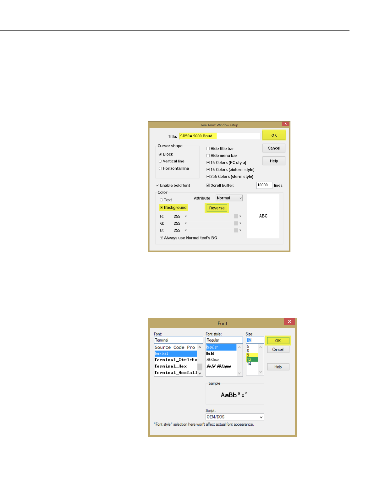
Appendix E. Tera Term QuickStart
4. Select Window from the drop-down menu list in Setup. Change the title
in the Window setup to SR50A 9600 Baud. The title is displayed at the
top of the terminal session screen.
By default, Tera Term works with white characters on a black background,
but can be changed to black characters on a white background. To change
the settings, click the radio button next to Background and click on the
Reverse button. Click on the OK button when finished making changes.
See FIGURE E-4.
FIGURE E-4. Windows Setup Changes
5. By default, Tera Term uses a font size of 9. If a larger font size is desired,
select Font from the drop-down list in Setup. Under Size, select the
desired font size. FIGURE E-5 shows the selection of 12 for the font size.
Click on the OK button when finished.
FIGURE E-5. Setting the Font Size
E-3
Page 72
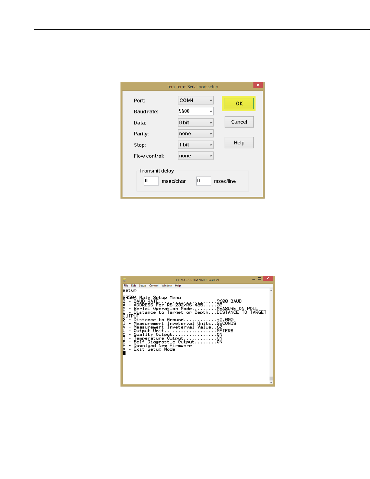
Appendix E. Tera Term QuickStart
6. Select Serial port from the drop-down list in Setup. Change the port to
reflect what you will be using to work with the SR50A/T. Leave the other
settings at their default values. Click the OK button when finished
(FIGURE E-6).
FIGURE E-6. Configuring the Serial Port
7. All changes needed to work with the SR50A/T are complete. You are back
at the main screen with the cursor blinking in the upper left corner of the
window. To see if communication has been established with the SR40A/T,
type setup and press enter. The word setup should appear in the terminal
window and the SR50A/T setup window should appear as well (FIGURE
E-7).
E-4
FIGURE E-7. Testing the Configuration
Page 73

8. To save this setup configuration, or any configuration, select Setup from
the top of the screen and select Save setup from the drop-down menu.
Give the file a name and save it to your Documents folder in Windows.
9. To load an existing setup, select Setup from the top of the screen. Select
Restore setup from the list and select the setup configuration that you
would like to load. Tera Term will not automatically connect to a COM
port and will remain disconnected until a COM port is selected. To do this,
select Serial port from the Startup drop-down menu. Verify the COM
port selection is correct and click on the OK button. This will activate the
port.
E.2 Firmware Update
E.2.1 Configure Tera Term to Send SR50A/T Firmware Update
Device Configuration Utility cannot be used to send a firmware update to a
SR50A/T.
General setup requires the following COM port configuration:
• BAUD rate: 38400
• Data Bits: 8
• Parity: None
• Stop Bits: 1
• Flow Control: XON/XOFF
• 25 ms line delay
Appendix E. Tera Term QuickStart
1. To configure Tera Term, follow steps 1 through 3 from Appendix E.1,
Configure Tera Term for Serial 9600 BPS Communication
2. Select Window from the drop-down menu list in Setup and change the
title to SR50A/T Firmware Download. The title is displayed at the top of
the terminal session screen.
3. Configure the serial port as follows (FIGURE E-8).
a. Click on the down arrow to the right of Baud rate and select 38400.
b. Click on the down arrow to the right of Flow control and select
XON/XOFF.
c. Enter 25 into the box to the left of msec/line.
d. Click on OK when all changes have been made.
(p. E-1).
E-5
Page 74
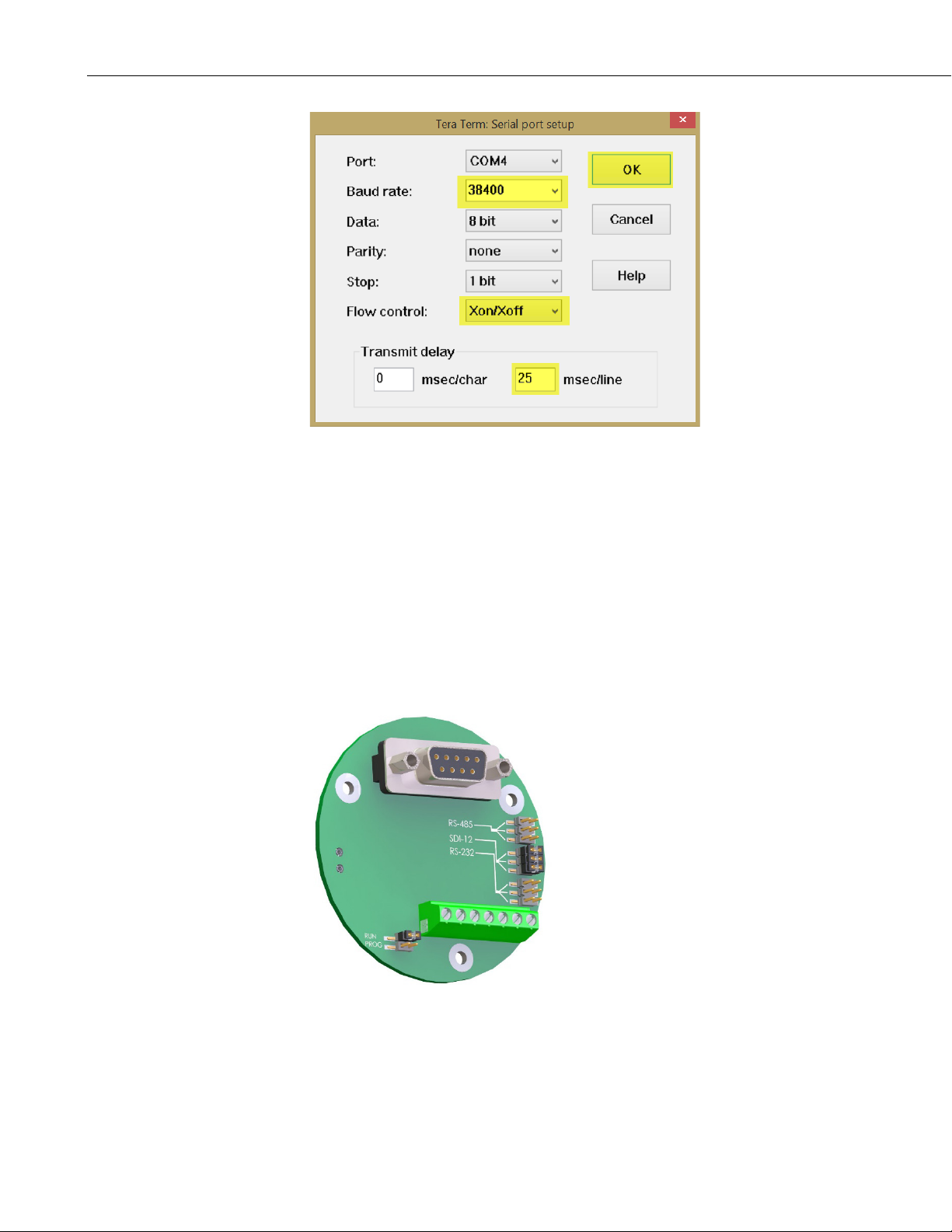
Appendix E. Tera Term QuickStart
FIGURE E-8. Configuring the Com Port to Send an Operating System
E.2.2 Sending New Firmware to a SR50A/T Sensor
Download a new firmware update from Campbell Scientific’s website,
www.campbellsci.com. Copy the TXT file to the
C:\CAMPBELLSCI\Lib\OperatingSystems folder. For this example, the file
SR50A_May_29_2007_V_1_3.TXT will be sent to a SR50AT. This firmware
update is used for either the SR50A or SR50AT.
To send a firmware update to the SR50A/T, the jumpers must be configured for
RS-232 operation and the jumper moved from RUN to PROG. See FIGURE
E-9 below.
E-6
FIGURE E-9. Jumper Settings
Firmware updates should only be performed at an appropriate workstation with
static control procedures in place. Failure to follow the procedure may cause
damage to the sensor.
Page 75

Appendix E. Tera Term QuickStart
NOTE
1. Ensure the SR50A/T is completely disconnected from power or
communication. The best way to do this is to simply unscrew the cable
connector from the SR50A/T.
2. Open the SR50A/T as follows:
a. Remove the six Phillips screws (slot-headed screws in older models)
that are located on the bottom side of the transducer housing.
b. The transducer housing will separate from the main metal housing.
c. Ensure that the screws are kept and set aside. On older models, the
O-ring is removable. Remove the O-ring and set it aside as well.
d. Disconnect the transducer housing assembly from the main metal
body by pressing down on the tab on the connector and gently pulling
the connectors apart. You may have to gently rock the connector from
side to side to get it to separate.
e. Remove the two Phillips screws from the bottom of the disk assembly.
Notice that these are the only two countersunk holes in the disk
assembly. Set the two screws aside.
f. The bottom disk assembly and the transducer housing have a
V-shaped notch that lines up with a mating V in the metal housing.
Separate the bottom disk from the main metal housing.
g. The circuit board will remain connected to the housing via the signal
wires.
h. Place the bottom disk/circuit assembly on the work bench with the
circuit board and DB-9 connector facing up. Ensure that no part of the
PCB is in contact with the metal lid or other conductive objects.
3. Move the jumper on the RUN/PROG header from the RUN position to the
PROG (program) position.
4. Connect to the DB-9 connector on the SR50A/T PC board.
5. Connect the cable back to the SR50A/T. The cable should be providing the
SR50A/T with power.
6. When power is reestablished, you will see a green LED light up close by
the RUN/PROG jumper. The LED will be on continuously with no
flashing.
7. Connect to the SR50A/T with Tera Term.
The SR50A/T will not accept any commands when in the program
mode.
8. In Tera Term select File at the top of the screen.
9. From the drop-down menu select Send file….
E-7
Page 76
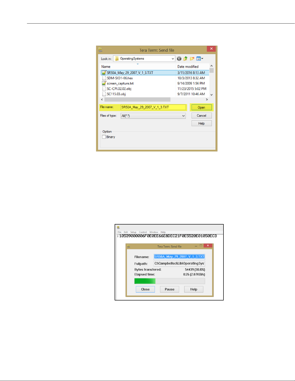
Appendix E. Tera Term QuickStart
10. Find the new firmware file and click Open. See the figure below.
11. Tera Term immediately begins sending the file when Open is selected.
The following will happen at this point:
a. The green light on the SR50A/T will start flashing and continue to
flash for several minutes after the file has been sent.
b. You will see the following screen indicating that the transfer process
is occurring in Tera Term. Directly above the Send File window, you
will see the lines of code being sent to the SR50A/T. Do not click on
any of the buttons in the Send File window. The window will
automatically disappear after the file has been sent.
The green light on the SR50A/T will continue to flash for several
minutes after the file has been sent. When the new firmware is loaded
and operational, the green light will come on steady. If there are any
errors, the LED will flash indicating that an error occurred.
E-8
12. If the LED does flash, then repeat the process and attempt to send the
firmware again.
Page 77

Appendix E. Tera Term QuickStart
13. After the reprogramming is successful, disconnect power from the sensor
and disconnect the serial cable from the DB-9 connector.
14. Move the jumper from PROG back to RUN.
15. Reassemble the sensor.
a. Line up the notch on the disk/circuit assembly with the V in the main
metal housing. Do not kink the wires going from the disk/circuit
assembly to the main metal assembly. Seat the disk/circuit assembly.
Put the two Phillips screws back in the countersunk holes. Do not over
tighten the screws. They should be snug.
b. Older transducer heads use a removable O-ring. Carefully seat the
O-ring back into place and make sure you won’t cut it when
assembling the transducer assembly.
c. Line up the connector on the transducer housing with the mating
connector on the disk/circuit assembly and slide it into place until the
tab clicks into place.
d. Line up the notch on the transducer housing with the V on the main
metal housing. Seat the housing.
e. Put the six screws back into the bottom of the transducer and tighten
them down.
16. Verify operation of the sensor by obtaining a measurement.
E-9
Page 78

Appendix E. Tera Term QuickStart
E-10
Page 79

Appendix F. SR50AH Heater Operation
The heater option on the SR50AH is intended for installations where rime ice
is problematic. The heater will help to prevent the ice from forming on the
transducer, which can impair proper operation of the sensor.
The heater option is easily identifiable as the transducer housing contains a
cable port for the heater supply cable.
Always use the heater option wired to switched 12 Vdc source. For batteryoperated solar-powered sites, Campbell Scientific recommends that the
heater’s power be turned off when icing conditions are not occurring to reduce
power requirements. The heater power must be turned off when operating at
temperatures of 25 °C or more.
CRBasic programs that control the heater are provided in Appendix B.4,
Heater Program Examples
F.1 Heater Specifications
(p. B-16).
Heater Resistance: 75 Ω
Nominal Operating Voltage: 12 V (ac or dc); use a properly conditioned,
Maximum Rated Wattage: 3 W
Maximum Rated Voltage: 15 V (ac or dc)
Maximum Operating
Temperature: 25 °C; turn the heater power off at
F.1.2 Heating Cable Requirements
Type: 2 conductor (twisted pair), Shielded
Diameter: 4 to 6 mm (0.16 to 0.24 in)
Recommended Gage: 22 AWG for lengths < 30 m (100 ft)
low-noise power source. A noisy power source
will affect operation of the sensor.
temperatures above 25 °C. This prevents
damage to the sensor and reduces power
consumption.
F-1
Page 80
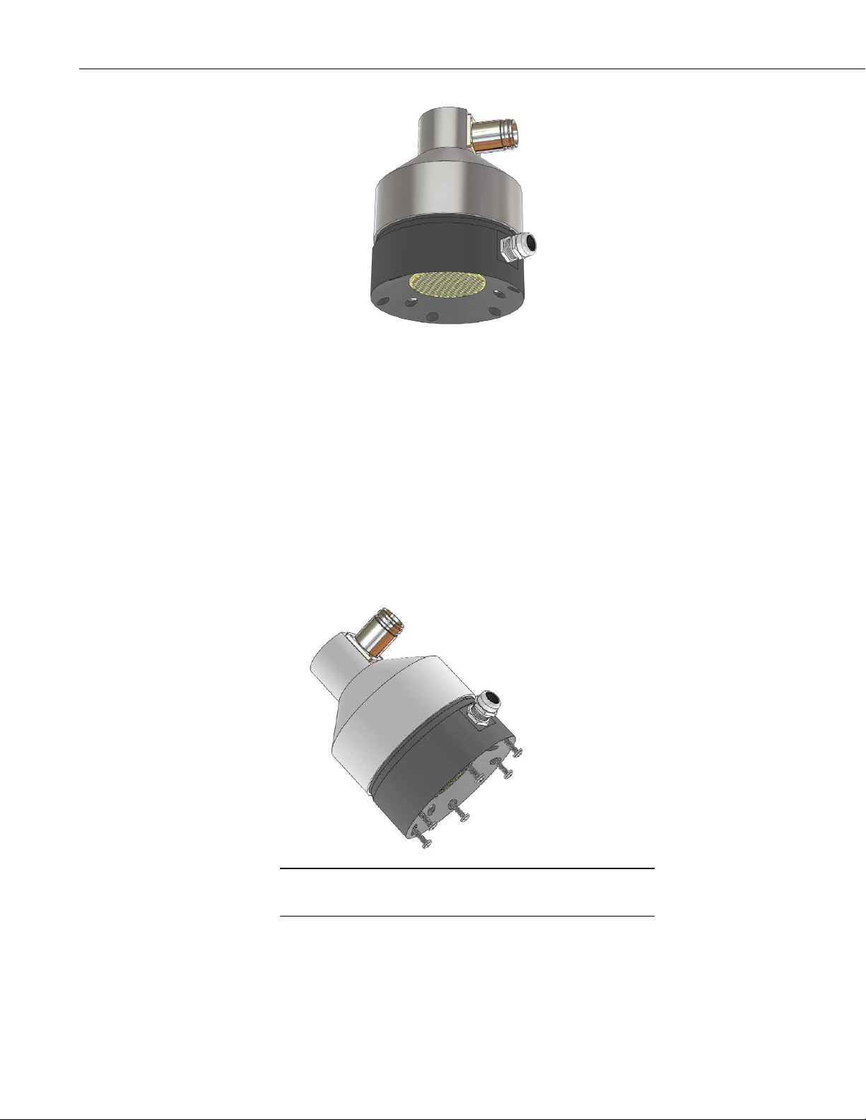
Appendix F. SR50AH Heater Operation
NOTE
FIGURE F-1. SR50AH Heater Option
F.2 Heater Maintenance
Most of the maintenance is the same as the maintenance for the standard
SR50A (Section 9, Maintenance and Troubleshooting
transducer and desiccant replacement is slightly different for the SR50AH.
When ordering replacement transducers, ensure that the Replacement
Transducer Maintenance Kit (pn 32571) is ordered.
(p. 15)). However, the
The procedure to disassemble the SR50AH for desiccant replacement or
transducer replacement is as follows:
1. Remove the six Phillips screws on the outermost hole pattern.
The screws used on the SR50A have changed from the slotted type
to Phillips.
F-2
Page 81
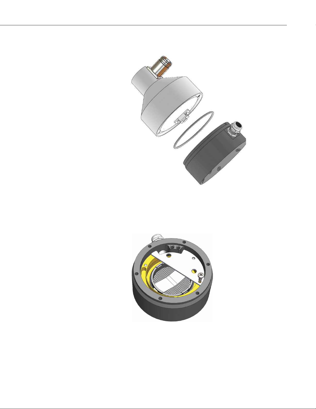
Appendix F. SR50AH Heater Operation
2. Separate the housing from the sensor body and disconnect the connector
from the transducer to the main sensor body.
3. To replace the desiccant, remove the desiccant holder plate with the
Phillips 4-40 screw. Cutting the tie strap will allow the old packets to be
removed for replacement. During reassembly, ensure that the desiccant
does not come in contact with the metal backing of the transducer. If only
the desiccant is being inspected or replaced, steps 4 and 5 are not required.
Steps 4 to 6 are required to replace the transducer only.
4. Your transducer kit comes with a replacement for the O-ring that seats
between the main sensor body and the plastic transducer housing. Ensure
that the new O-ring is used when reassembled.
F-3
Page 82
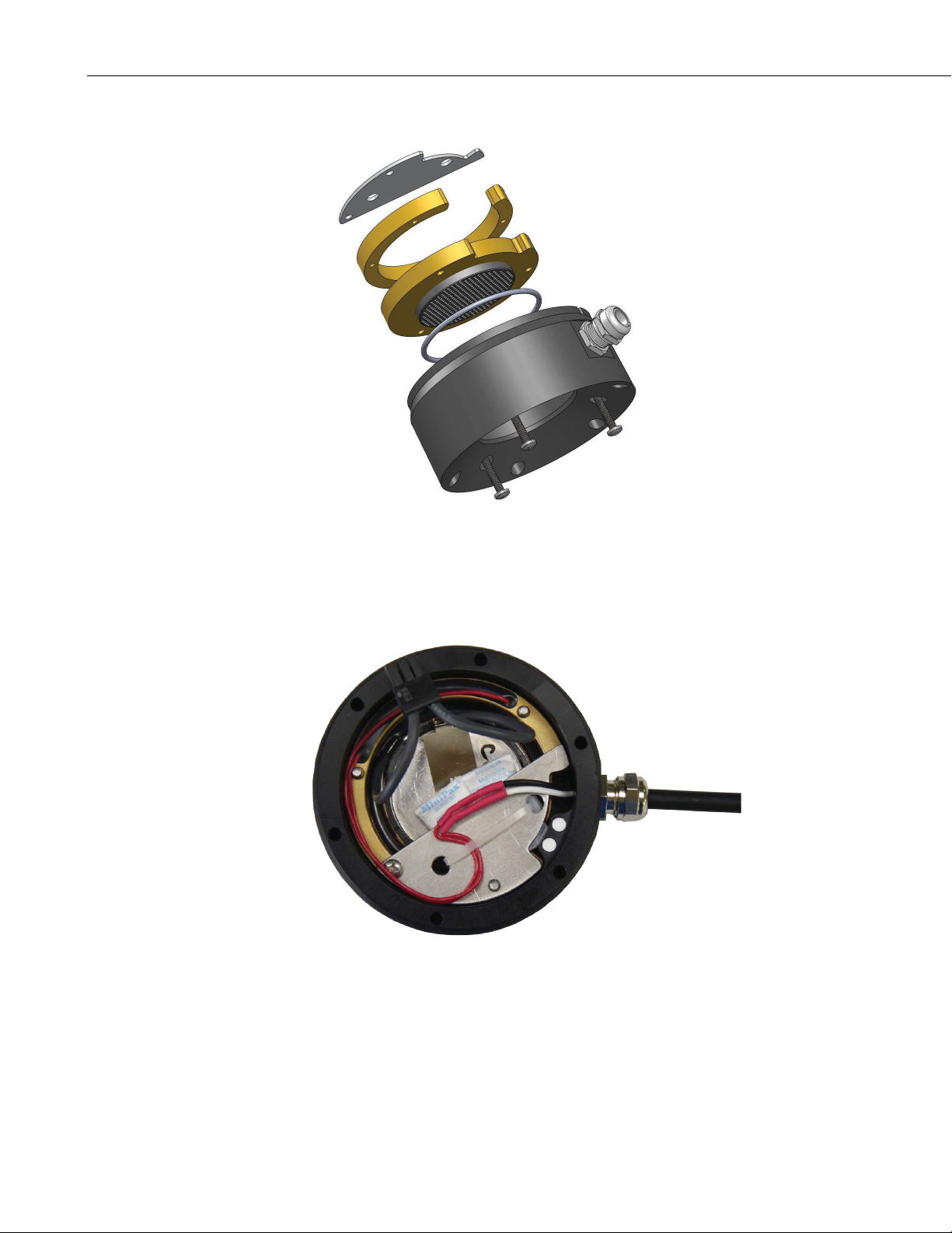
Appendix F. SR50AH Heater Operation
5. Remove the three screws from the innermost hole pattern as shown.
6. Replace the transducer assembly and the second O-ring that seats under
the transducer assembly.
7. Reassemble the sensor in the reverse order. Please observe the orientation
of the parts, wiring, and desiccant.
FIGURE F-2. Complete Transducer Assembly with Power Connection
F-4
Page 83

Page 84

Campbell Scientific Companies
Campbell Scientific, Inc.
815 West 1800 North
Logan, Utah 84321
UNITED STATES
www.campbellsci.com • [email protected]
Campbell Scientific Africa Pty. Ltd.
PO Box 2450
Somerset West 7129
SOUTH AFRICA
www.campbellsci.co.za • [email protected]
Campbell Scientific Southeast Asia Co., Ltd.
877/22 Nirvana@Work, Rama 9 Road
Suan Luang Subdistrict, Suan Luang District
Bangkok 10250
THAILAND
www.campbellsci.asia • [email protected]
Campbell Scientific Australia Pty. Ltd.
PO Box 8108
Garbutt Post Shop QLD 4814
AUSTRALIA
www.campbellsci.com.au • [email protected]
Campbell Scientific (Beijing) Co., Ltd.
8B16, Floor 8 Tower B, Hanwei Plaza
7 Guanghua Road
Chaoyang, Beijing 100004
P.R. CHINA
www.campbellsci.com • [email protected]
Campbell Scientific do Brasil Ltda.
Rua Apinagés, nbr. 2018 ─ Perdizes
CEP: 01258-00 ─ São Paulo ─ SP
BRASIL
www.campbellsci.com.br • [email protected]
Please visit www.campbellsci.com to obtain contact information for your local US or international representative.
Campbell Scientific Canada Corp.
14532 – 131 Avenue NW
Edmonton AB T5L 4X4
CANADA
www.campbellsci.ca • [email protected]
Campbell Scientific Centro Caribe S.A.
300 N Cementerio, Edificio Breller
Santo Domingo, Heredia 40305
COSTA RICA
www.campbellsci.cc • [email protected]
Campbell Scientific Ltd.
Campbell Park
80 Hathern Road
Shepshed, Loughborough LE12 9GX
UNITED KINGDOM
www.campbellsci.co.uk • [email protected]
Campbell Scientific Ltd.
3 Avenue de la Division Leclerc
92160 ANTONY
FRANCE
www.campbellsci.fr • [email protected]
Campbell Scientific Ltd.
Fahrenheitstraße 13
28359 Bremen
GERMANY
www.campbellsci.de • [email protected]
Campbell Scientific Spain, S. L.
Avda. Pompeu Fabra 7-9, local 1
08024 Barcelona
SPAIN
www.campbellsci.es • [email protected]
 Loading...