


USER MANUAL
Firmware revision 6.1
Software revision 2.3
MADE IN ITALY

INDEX
1)GENERAL WARNINGS.
2)PACKAGE AND HANDLING.
3)INCLUDED ACCESSORIES.
4)CONNECTIONS AND CONTROLS.
5)START-UP AND SHUT-DOWN PROCEDURES.
6)CRUMAR MOJO OVERVIEW.
7)EDIT AND PROGRAMMING MODE.
8)BONUS SOUNDS.
9)UPDATES.
10)MAINTENANCE AND WARRANTY.
11)ADDENDUM.
2
1) GENERAL WARNINGS
READ CAREFULLY BEFORE CONNECTING ELECTRICAL CABLES.
∙Do not place the instrument in wet or dirty environments.
∙Do not remove the protective coverings.
∙Do not touch the AC plug with wet hands.
FACTORY DEFAULTS
∙The CRUMAR Mojo accepts voltages from 100V to 240V AC 50-60Hz through the original power supply. Be sure that local electrical standards are compliant with the instrument.
∙The serial number, international standards and other informations are printed on the plate positioned in the back panel near power inlet and in the power supply.
DO NOT REMOVE THE TOP PANEL FOR ANY REASON.
IN THE EVENT THAT SUPPORT OR TECHNICAL ASSISTANCE IS REQUIRED, PLEASE CONTACT YOUR CRUMAR DEALER OR AN AUTHORIZED CRUMAR TECHNICAL CENTER.
THE MAIN POWER CONNECTION IS LOCATED ON THE REAR OF THE INSTRUMENT ON THE LEFT SIDE. THE POWER BUTTON IS ON THE TOP OF THE INSTRUMENT ON THE LEFT SIDE.
BEFORE CONNECTING THE MAIN POWER CABLE, CONNECT ALL OTHER CABLES FIRST.
3

When you are using the instrument, please be aware of the following:
∙Do not cover any of the instrument’s ventilation holes.
∙Air must circulate freely around the instrument.
∙Do not set the instrument on a surface with excessive vibration.
∙Do not expose the instrument to electro-magnetic interference.
∙Do not expose the instrument to heat, cold, wet or dust.
∙Do not leave the instrument in direct sunlight.
∙Do not expose the instrument to electrostatic forces.
∙Do not place items with flames, such as candles or lighters, on the instrument.
∙Do not place the instrument on anything containing water or other fluids.
If any foreign objects enter the instrument, please contact your dealer or an authorized CRUMAR technical center.
AC Power Information
1.Do not forcibly unplug the power cord.
2.When not in use, unplug the AC cable from the instrument.
3.Unplug the AC cable during thunderstorms.
2) PACKAGE AND HANDLING
Carefully remove the instrument from its packaging. The CRUMAR Mojo weighs just over 37 lbs (17 kg).
Please set the CRUMAR Mojo on a stand rated at 44 lbs (20 kg).
Please keep the original packaging material for future use.
The packaging bag is not a toy. Keep out of reach of children.
CRUMAR is not responsible for any injuries incurred by incorrect use of the organ or the packaging materials.
4

3)INCLUDED ACCESSORIES
∙CRUMAR Mojo organ
∙User manual
∙Power supply
∙IEC and ROHS compliant AC plug (US plug or EU plug)
The organ can be equipped with additional, optional accessories like mojoeditor, sustain pedal, rotary effect control pedal, half-moon rotary effect control, soft or hard case. For information about purchasing original CRUMAR accessories, please contact your dealer or CRUMAR directly.
4) CONNECTIONS AND CONTROLS
The CRUMAR Mojo is suitable for use in most countries worldwide. Its power supply accepts voltages from 100 to 240 Volts AC. For more details, please contact your dealer or an authorized CRUMAR service center. The CRUMAR Mojo should be used with a power source that is compliant with the standards listed on the label located in the rear of the original power supply of the instrument.
If the instrument will be used in countries with different electricity standards, please contact your dealer or an authorized CRUMAR service center.
It is recommended that only compatible devices or accessories in perfect working condition be connected to the instrument. Connecting broken or incompatible devices to the CRUMAR Mojo’s sockets, inputs and outputs could damage the instrument. Do not insert foreign objects into ventilation holes or into sockets and plugs. If you are not sure about compatibility of your equipment, we strongly recommend that you contact your dealer or an authorized CRUMAR service center.
Important notes on Power supply.
Depending on your country, Mojo power supply can be of class 1 or class 2 type.
If your instrument doesn’t work properly (power off after a while, no sound after a while ecc) or you notice noise on your instrument (power supply, ground loop noise), please check connections and avoid ground loops; if this doesn’t solve your problem, if your power supply is Class 1 type, you can remove earth connection from the AC connector to the AC main (also using an adapter). Please remember that using Vintage Leslie speakers (also modified ones) connected to Crumar Mojo, can amplify ground loop problems and changing speed on the Vintage Leslies can cause power off of the instrument as protection.
CRUMAR is not responsible of any damage caused by these operations.
5

Back Panel Connections and Controls (Fig.1):
Fig.1
1.Power: This plug is used to connect the CRUMAR Mojo power supply (12 Volt CC). Do not use any power supply other than the original unit that shipped with the instrument.
2.Motherboard Connections Access Slot: Connections to the motherboard can be accessed in this panel. The motherboard connections should be used only for updates and advanced instrument configuration. A VGA-compatible monitor can be connected using a 15-pin connection to the blue port. A mouse or keyboard can be connected using the din PS/s purple or green ports or any available USB ports. USB ports can also be used for connecting other devices such as USB flash drives for data transfer and for connect MOJOEDITOR. The LAN port and the blue, green and purple audio connection ports have been disabled.
3.Headphones (stereo): This output is used to connect headphones for individual use of the instrument.
4.Main Audio Out - L & R (Left and Right channels): These outputs are used to connect the instrument to the main amplification system. The CRUMAR Mojo should be connected to a stereo amplification system to provide the fullest sound.
Audio out of mojo are balanced but it can accept unbalanced cables too. In normal operation, the rotary speaker simulation is output in stereo. The CRUMAR Mojo can additionally create a vertical rotary speaker simulation using
CRUMAR’s exclusive “V.S. Technology.” When using the vertical simulation, the output from the R channel provides the bass/rotor simulation and the L channel provides the treble/horn simulation. An internal crossover filters the signal to the appropriate output. To fully benefit from the vertical simulation and to best simulate the sound image of a rotary speaker, place the speaker to which the L channel is connected above the speaker to which the R channel is connected. On latest software revision, if you select other combinations of sound (for
example combination 2 tonewheel organ + tines e-piano) using out split mode, you will find the organ on left output and e-piano on right output.
Additional settings for the L and R outputs can be chosen. (See Section 7: Edit and Programming Mode.)
6

5.MIDI IN: This five-pole DIN connection is used to connect the CRUMAR Mojo to a device capable of sending MIDI data, such as a master keyboard or a
pedal board. This connection is also used when updating the instrument’s firmware with MIDI Firmware Upload (MFU) technology.
PLEASE NOTE: if your organ is a rev.C, Midi in plug is not working if you have a usb cable plugged in the USB – MIDI PLUG.
6.MIDI OUT: This five-pole DIN connection is used to connect the CRUMAR Mojo to a device capable of receving MIDI data. The instrument’s controls are configured as follows:
∙Channel 1: Drawbars, pots and all other upper manual controls
∙Channel 2: Lower manual
∙Channel 3: Lower manual if “Pedal to Lower” function is enabled
CAUTION: It is highly recommended not to connect or disconnect MIDI cables with the instrument on. The instrument can be damaged or work incorrectly.
7.USB – MIDI PLUG : This connection is used to send and receive MIDI data from the CRUMAR Mojo to a computer via USB without the need for a converter. For example, the CRUMAR Mojo could be used to play sounds from a softwarebased synthesizer on a laptop computer. Please check software driver compatibility on the computer before connecting the CRUMAR Mojo. It can be used for firmware upgrade too (only on mojo rev.C)
8.Swell: This 6.3 mm stereo output jack connection is used to connect an expression pedal to the CRUMAR Mojo.
Please use only genuine CRUMAR expression pedals. Other pedals and/or equipment can damage the instrument. For a compatibility list, please contact CRUMAR MUSICAL INSTRUMENTS.
CAUTION: Do not connect or disconnect the expression pedal with the instrument on. The instrument can be damaged or work incorrectly.
7
9.Sustain: This 6.3 mm stereo output jack connection is used to connect an optional momentary “on/off” type of sustain pedal to the CRUMAR Mojo. The instrument accepts both pedals configured as normally closed and pedals configured as normally open.
The instrument automatically configures the pedal at start-up. Connect the pedal to the instrument before turning the instrument on. The internal organ sounds of VBC CE 2 organ software may not respond to MIDI sustain messages.
10.Rotary Speed: This 6.3 mm stereo output jack connection is used to connect an optional foot pedal or front-mounted half-moon switch to control the speed of the internal rotary speaker simulation. Use only original CRUMAR pedals or switches. Other pedals or switches could damage the instrument.
The instrument automatically configures the pedal or switch at start-up. Connect the pedal or switch before turning the instrument on.
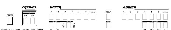
Front Panel Controls (Fig. 2):
Fig. 2
Power: This button is used to turn the instrument on and off. Pressing this button initiates the start-up boot process. The LED light sequence across the top panel displays while the instrument is starting.
To turn the instrument off, hold the Power button for four seconds.
∙Cabinet Section: These buttons control the rotary speaker simulation.
“Run/Stop” – This button controls whether the horn and rotor of the simulated rotary speaker are turning. When set to “Stop,” the horn and rotor do not move. This is often referred to as “Brake.” When set to “Run,” th e horn and rotor spin according to the setting of the “Fast/Slow” button.
“Fast/Slow” – This button controls the speed of the horn and rotor when the
“Run/Stop” button is set to “Run.” The speed change s from “Fast,” which provides a vibrato effect, to “Slow,” which provides a chorus effect.
8
 Loading...