

Page 1
CRU® WiebeTech® Ditto® Shark
User Manual
Features
• Standalone product—operates without a PC or a Ditto Forensic FieldStation
• Captures Internet and VOIP traffi c with virtually no packet loss*
• Captures sustained 10/100 Mbps network traffi c and short burst gigabit network traffi c*
• Filter and capture network traffi c to a tcpdump/Wireshark-compatible PCAP fi le
• Optional live capture stream (rpcap) interface for Wireshark
• Removable drive carrier for data storage
• Fail-safe design continues passing through network traffi c if power is lost
• Free fi rmware updates for registered users
*Packet loss is a function of the type and saturation level of traffi c on the tapped network
Page 2

CRU Ditto Shark User Manual
2
TABLE OF CONTENTS
1 General Information 3
1.1 Package Contents 3
1.2 Identifying Parts 3
1.3 LED Behavior 3
1.4 Thermal Cooling 3
1.5 How to Use the Ditto Shark 4
2 Setup 4
3 Browser Interface 6
3.1 Accessing the Browser Interface 6
3.2 Icons Used in the Browser Interface 6
3.3 User Accounts 6
4 Home Screen 7
4.1 Action 7
4.1.1 Network Capture 7
PCAP Network Capture 7
Live Network Capture 8
Simultaneous PCAP and Live Network
Capture
4.1.2 Erase Destination Disk 9
4.2 Investigation Info 10
4.3 System Settings 11
4.4 Current Status 11
4.5 Disks 11
4.5.1 View Hexidecimal Data 11
4.5.2 View Snapshot Data 11
4.6 System Log 12
5 Confi gure Screen 12
5.1 System 12
5.2 Network 14
5.3 Erase 17
5.4 Network Capture 17
5.5 Naming 19
5.6 Quick Start 19
6 Admin Screen 20
6.1 User Accounts 20
6.2 Permissions 20
6.3 Adding a New User 21
6.4 Editing an Existing User 21
6.5 Deleting a User 21
7 Logs Screen 21
8 Utilities Screen 22
8.1 System Maintenance 22
8.1.1 Firmware Upgrade 22
8.1.2 Confi guration 22
8.1.3 Other Buttons 22
8.2 Upgrade Log Messages 23
8.3 Import Log Messages 23
9 Using the Front Panel Interface in Standalone Mode 23
9.1 How to Navigate 23
9
9.2 Menu Screens 23
9.2.1 Status 23
9.2.2 Perform Action 24
9.2.3 Investigation Info 24
9.2.4 Settings 25
9.2.5 Disk Info 28
9.3 Factory Reset 28
10 Stealth Mode 28
11 Advanced Features and Functions 28
11.1 Using iSCSI Devices 28
11.2 Using NFS and SMB (Samba) Shares 30
11.3 Using and Confi guring Network Capture Filters 31
12 Upgrading Firmware 32
13 Technical Specifi cations 34
Protecting Your Digital Assets
TM
Page 3
CRU Ditto Shark User Manual
3
1 GENERAL INFORMATION
1.1 PACKAGE CONTENTS
The following list contains the items that are included in the
complete confi guration for this device. Please contact CRU if
any items are missing or damaged:
Item Quantity
Ditto Shark 1
40W 12V AC adapter 1
Power cord 1
Unitized SATA-to-eSATA + Mini-Fit power cable 2
Ethernet cable (RJ45) 2
4GB SD card (pre-installed) 1
User Manual 1
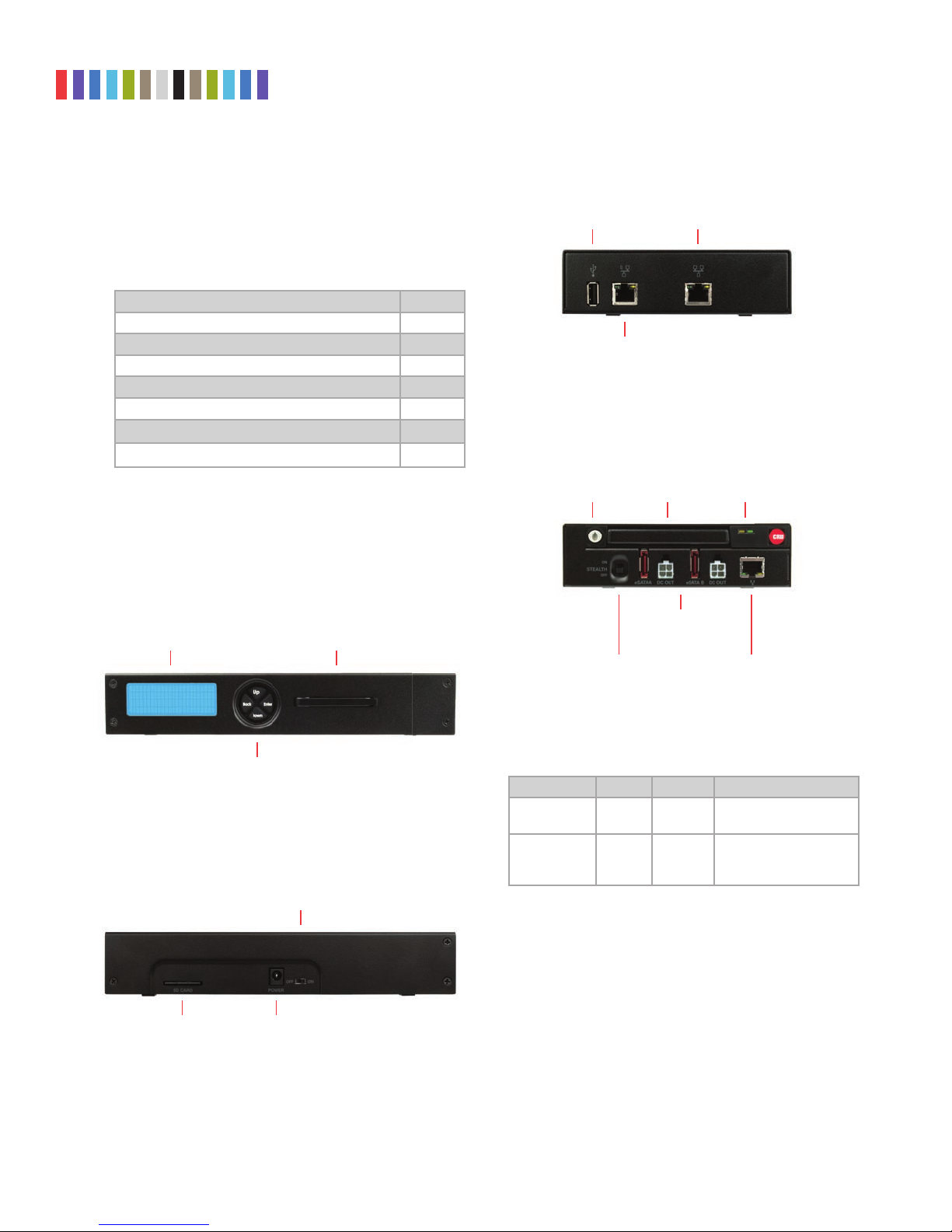
1.2 IDENTIFYING PARTS
Take a moment to familiarize yourself with the parts of the
product. This will help you to better understand the following
instructions.
FRONT PANEL
LCD Display
Hanging Hook
NETTAP INTERFACE
RJ45 Gigabit
USB 2.0 Port
RJ45 Gigabit
Ethernet Connection
Ethernet Connection
DESTINATION INTERFACE
DP20 Keylock/
Eject Button
Stealth Mode
Switch
DP20
Carrier
eSATA Ports &
Power Connectors
DP20 Status
Lights
RJ45 Ethernet
Connection
Navigation
Buttons
REAR OF THE UNIT
Power Switch
SD Card Slot Power Input for
AC Adapter
Protecting Your Digital Assets
1.3 LED BEHAVIOR
LED COLOR STATE DESCRIPTION
DP20 Power Green Solid
DP20 Drive
Activity
Amber
Solid or
Blinking
The DP20 is powered
on.
The drive inside the
DP20 is being accessed.
1.4 THERMAL COOLING
The Ditto Shark is a passively cooled system that pulls heat
out of the processor and other electronics into the all-metal
housing where it dissipates. The heat generated by the Ditto
Shark is an intended design feature that eliminates the need
of a noisy internal cooling fan and drastically reduces the
amount of particulates that are pulled through the system.
TM
Page 4
CRU Ditto Shark User Manual
4
1.5 HOW TO USE THE DITTO SHARK
The Rear Interface side of the Ditto Shark has a power switch, a 12V input for the included power supply
and an SD card slot from which to store configuration data.
Use the NetTap Interface side of the Ditto Shark to insert the Ditto Shark in between the target computer
and the network it is connected to. The available connections include two RJ45 gigabit Ethernet ports and a
USB 2.0 port for use with USB storage devices, a keyboard, or a wifi adapter. Both RJ45 ports are direction
agnostic, so it doesn’t matter which port is used to connect to the network and which is used to connect to
the target computer.
Use the Destination Interface side of the Ditto Shark to store acquired data. The destination output con
nections include a CRU DataPort DP20 and two eSATA ports for SATA disks or eSATA devices. It also
includes an RJ45 gigabit Ethernet port to allow network access to the Ditto Shark’s Browser Interface (see
Section 3) and a stealth switch that will turn off all external lights and enable nightvision display via Stealth
Mode (see Section 10).
NOTE
CRU recommends that you switch the power off to the Ditto Shark when you add or remove a device
from it in order to avoid disk damage and data corruption.
2 SETUP
a. Leave the Ditto Shark disconnected from the network until you have configured it
properly using the steps below.
b. Connect the power cable to the rear of the Ditto Shark and turn the Ditto Shark on with
the power switch located on the rear of the unit.
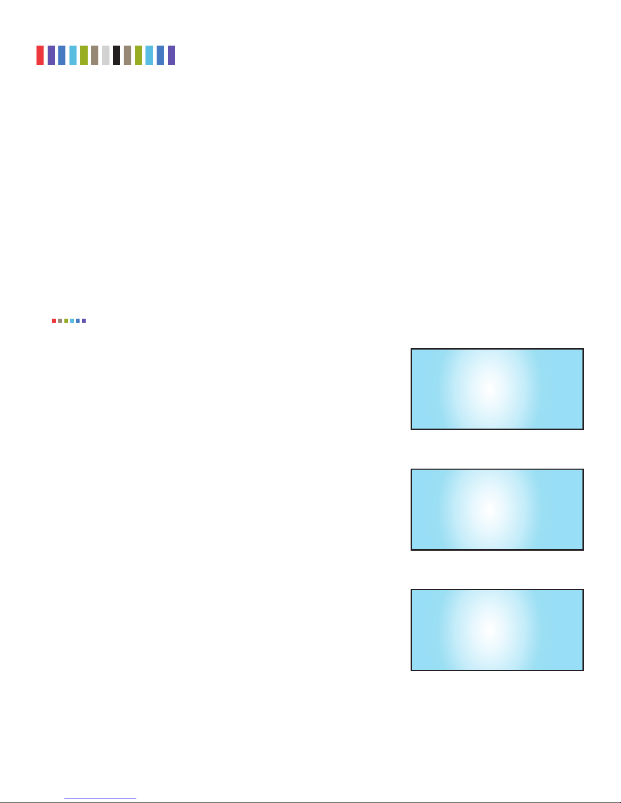
c. Press the Down navigation button on the Ditto Shark until you reach the “Settings”
menu (see Figure 1) on the Front Panel. Then press Enter to view the Settings.
d. Press Up or Down until you reach the “Dst Network Settings” screen shown in Figure
2 and press Enter.
e. Press Up or Down until you reach the “Dst Network” screen shown in Figure 3.
f. If the text on the second line says “Disabled”, press the Enter button to edit the set
ting. Press Up once and then Enter to commit the change. If the text says “Enabled”,
continue to the next step.
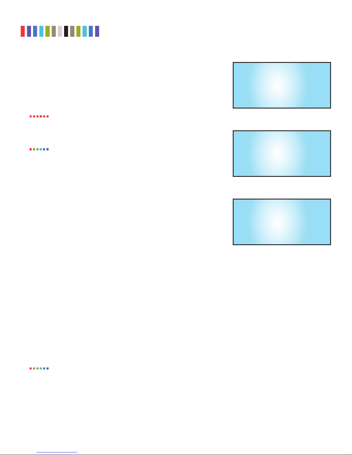
g. Press Up or Down until you reach the “Dst Network Mode” screen shown in Figure 4
and then press Enter to edit the setting.
Figure 1. A depiction of the “Settings” menu on the
Ditto Shark.
-
Figure 2. A depiction of the “Dst Network Settings”
screen on the Ditto Shark.
-
Settings
View/Edit >
Dst Network Settings
View/Edit >
h. The Ditto Shark has three connection modes. Press Up or Down to choose which way
you would like to use the Ditto Shark and press Enter to select it.
• Client (DHCP): The Ditto Shark acts as a client on the network and automatically
detects network parameters (e.g. IP address, gateway, etc.) from a DHCP server
on the network. DHCP is the protocol used by most network environments today.
Unless your network administrator directs otherwise, you should probably use this
mode.
Protecting Your Digital Assets
TM
Dst Network:
Disabled
Edit >
Figure 3. A depiction of the “Dst Network” screen on
the Ditto Shark.
Page 5
CRU Ditto Shark User Manual
5
• Client (Static IP): The Ditto Shark acts as a client on the network and you manu-
ally input all network parameters (e.g. IP address gateway, etc.).
• Server: The Ditto Shark acts as the master DHCP server on the network and you
manually input all network parameters. The server mode is also used to directly
connect Ditto Shark to a computer.
Dst Network Mode:
Client (Static IP)
Edit >
STOP!
NOTE
i. If you selected Client (Static IP) or Server, then follow additional steps in Section 2.1
After your first-time setup, always ensure that the Ditto Shark is properly config
ured to use the proper connection mode before you connect your Ditto Shark to
a different computer or network. An improperly configured Ditto Shark can cause
networking conflicts on the host network.
The Ditto Shark is configured by default to use “Network Client (DHCP)” mode
so that it will not conflict with the most common types of networks.
below.
If you selected Client (DHCP), you are ready to start using the Ditto Shark. You may
access its settings via the Browser Interface (see Sections 3-8) or via the Front Panel
(see Section 9).
2.1 ADDITIONAL STEPS FOR “CLIENT (STATIC IP)” AND “SERVER”
a. Press Up or Down until you reach the “Dst IP Address” screen shown in Figure 5.
b. Press Enter to edit the IP address. You can use a keyboard that you’ve attached
to the USB 2.0 port on the “NetTap Interface” side of the Ditto Shark to enter the
static IP address your network administrator gave you.
If you do not have a keyboard, press Back and Enter to scroll the cursor right and
left, and press Up or Down to increase or decrease the number highlighted by the
cursor.
-
Figure 4. A depiction of the “Dst Network Mode”
screen on the Ditto Shark.
Dst IP Address:
10.10.0.1
Edit >
Figure 5. A depiction of the “Dst IP Address” screen
on the Ditto Shark.
Dst Subnet Mask:
255.0.0.0
Edit >
Figure 6. A depiction of the “Dst IP Address” screen
on the Ditto Shark.
c. When you have finished, press Enter until the cursor has moved all the way to the right, and then press
Enter once more to commit the changes.
d. Press Up or Down until you reach the “Dst Subnet Mask” screen shown in Figure 6 and press Enter to
edit the subnet mask.
e. Use the keys on the Front Panel or your USB keyboard to enter the subnet mask your network admin
istrator gave you. If your administrator did not give you a subnet mask, the default setting will usually
suffice.
f. When you have finished, press Enter until the cursor has moved all the way to the right, and then press
Enter once more to commit the changes.
NOTE
Protecting Your Digital Assets
Additional network parameters can be input using the Browser Interface’s Configure screen (see Sec
tion 5.2)
You are ready to start using the Ditto Shark. You may access its settings via the Browser Interface (see Sec
tion 3) or via the Front Panel (see Section 9).
TM
-
-
-
Page 6
CRU Ditto Shark User Manual
6
3 BROWSER INTERFACE
The Ditto Shark can be confi gured and operated either from the Front Panel (see Section 9) or through a web
browser.
3.1 ACCESSING THE BROWSER INTERFACE
a. Using the Front Panel, navigate to “Dst Network Settings” → “Dst IP Address”.
b. Type the IP address shown into your web browser.
c. Log into the Browser Interface (the default user name and password for the administrator account are
both “admin”).
NOTE
CRU recommends that you change the admin account password and create user accounts for individual users as best data management practices.
You are now ready to use the Browser Interface to confi gure settings and preview, image, or clone attached
disks.
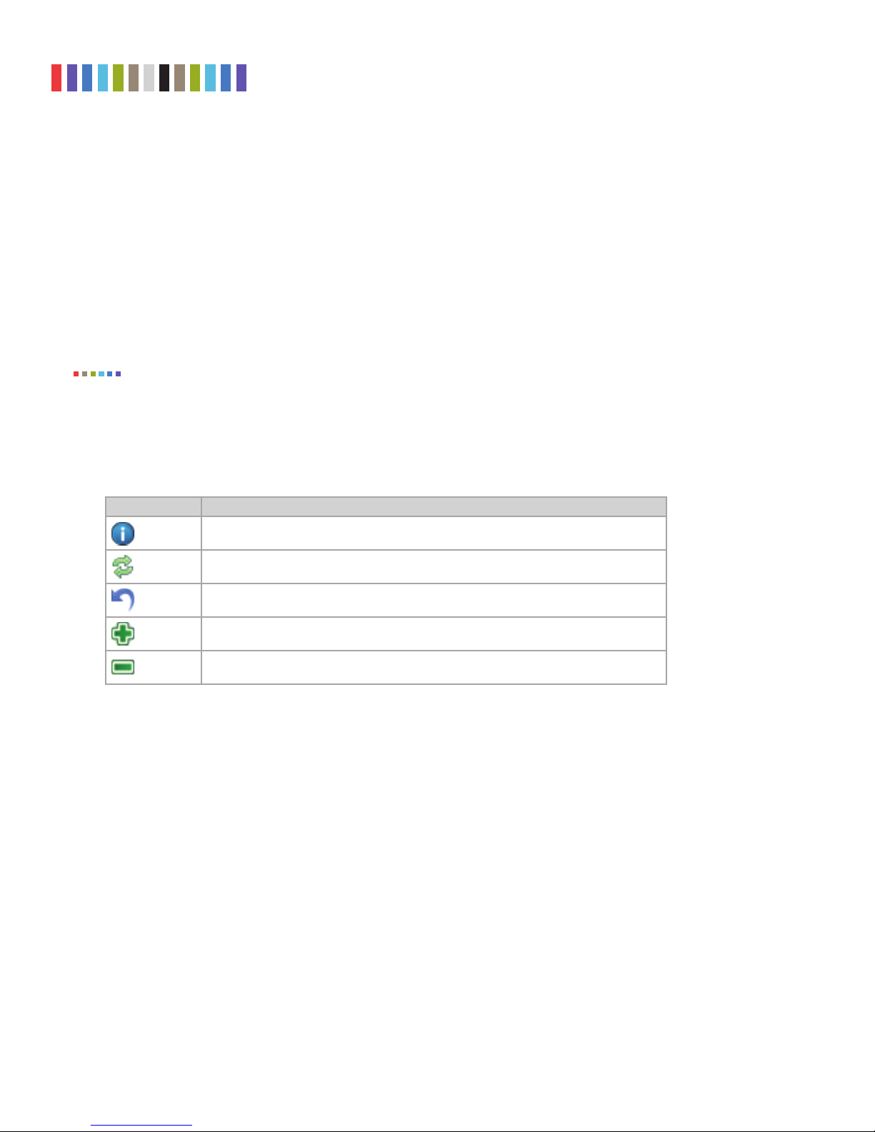
3.2 ICONS USED IN THE BROWSER INTERFACE
The Browser Interface uses several icons that may be clicked on to perform certain actions.
ICON ACTION
Information
Refresh
Reset
Add
Remove
Opens a window with a brief description of the setting that the information icon appears
next to.
Refreshes the fi eld that the icon appears next to in order to give updated information.
Loads the defaults for the setting that the Refresh icon appears next to.
Adds a user defi ned fi eld to a list of items.
Removes a user defi ned fi eld from a list of items.
3.3 USER ACCOUNTS
The Ditto Shark employs a user account system to control access to its features. The “Login” screen
presents you with the ability to log in through http, or you can click the Secure Login (HTTPS) link to log
in securely. Accept the certifi cate and/or continue to the website, even if your browser tells you it does not
recognize it.
The default user name and password for the Administrator account are both “admin”. CRU recommends
that you change the admin account password and create user accounts for individual users as best data
management practices.
Click on the Log Out button at the top right of the Browser Interface to log out.
Protecting Your Digital Assets
TM
Page 7
CRU Ditto Shark User Manual
7
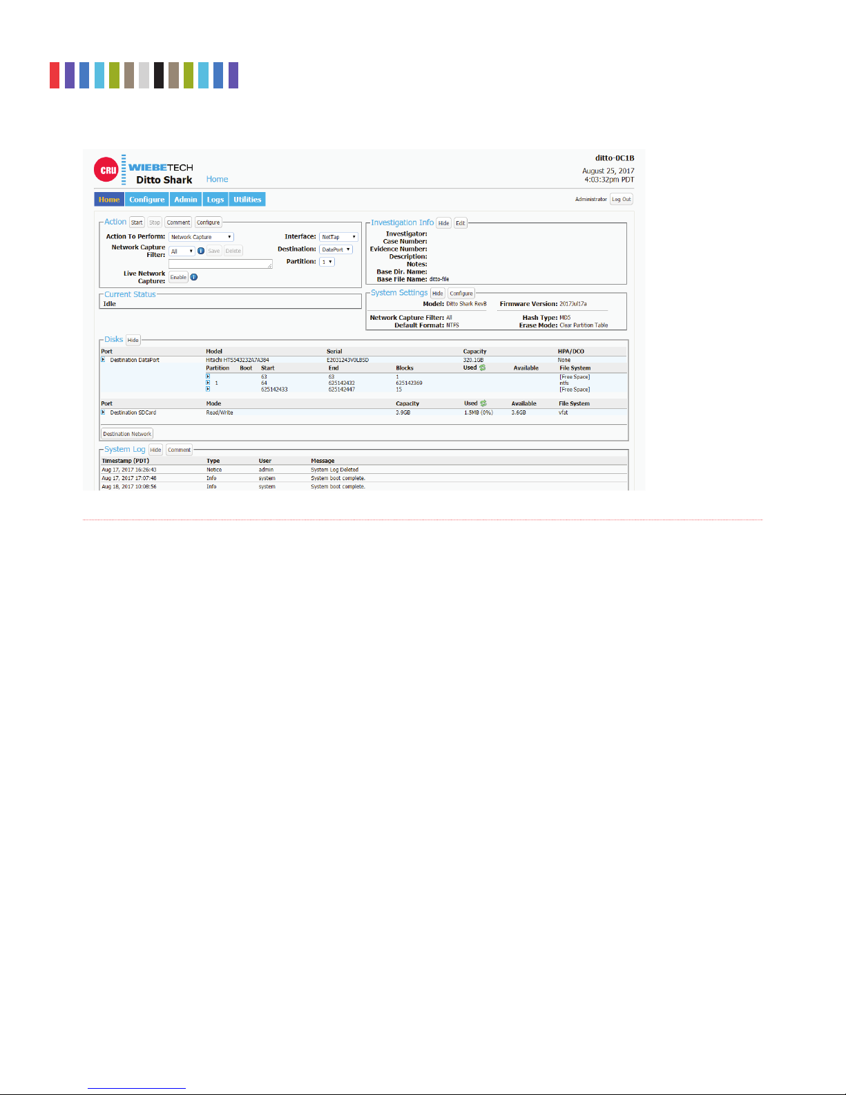
Figure 7. The “Home” screen.
4 HOME SCREEN
The “Home” screen is where you will perform most of your operations with the Ditto Shark, and is the default
screen to load upon logging into the Browser Interface. Click on the Home tab to access the “Home” screen
from any other area of the Browser Interface.
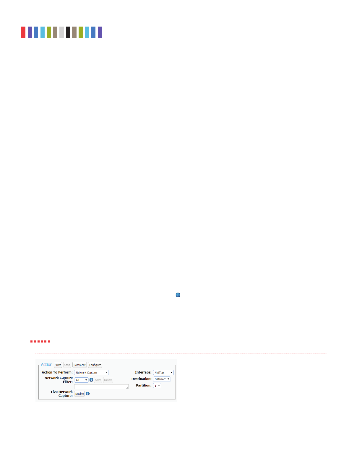
4.1 ACTION
The “Action” panel lets you start, abort, and document the following actions. The “Start” button begins the
action. The “Abort” button stops the action in progress. Click the Comment button to write a note that will
be appended to the log. Click the Configure button to modify the default settings for each action, which
can also be modified on the “Configure” screen (See Section 5).
4.1.1 Network Capture
The Ditto Shark provides two methods of capturing network traffic that can be combined and used
simultaneously if you wish. The first method captures network traffic and stores it in a series of incre
mented PCAP files on the local target destination. The second method captures network traffic in
real-time and outputs it to a remote monitor that uses a third-party Wireshark network protocol analyzer.
Instructions for both methods as well as instructions for using them simultaneously can be found below.
PCAP Network Capture
a. Using the Browser Interface, select Network Capture from the “Action to Perform” drop-down
box.
b. Select the network capture filter from the “Network Capture Filter” drop-down box or type in
the ports you wish to capture in the text box directly below that using the syntax “port ## or ##”
without quotes (e.g. port 80 or 81 or 443).
-
Protecting Your Digital Assets
TM
Page 8
CRU Ditto Shark User Manual
8
c. Select “NetTap” from the “Interface” drop-down box.
d. Select the media from the “Destination” drop-down box that you want Ditto Shark to save your
captured data.
e. Select the partition on the destination media you want to capture to from the “Partition” drop-
down box.
f. Bypass “Live Network Capture” and leave it disabled.
g. Click the Start button to begin capturing network data. When you are fi nished, click the Stop
button.
You can view the log of the network capture action by scrolling down to the “System Log” panel
on the “Home” screen. Find and click on the latest link, which will be denoted by a fi lename with a
date/timestamp format: “S_yyyymmddhhmmss”. Alternatively, you can click on the Logs button
from the top menu bar.
You can view the data retrieved from the network capture action by examining the destination
media, which will contain a folder named with the same data/timestamp format: “S_yyyymmd-
dhhmmss”, which includes the PCAP fi les containing the captured data, an XML fi le containing the
log information of the network capture, and—if hashing is enabled—a TXT fi le that contains each of
the generated PCAP fi les’ MD5 or SHA-1 hash value (see Section 5.1.2 to enable hashing).
STOP!
Live Network Capture
a. Using the Browser Interface, select Network Capture from the “Action to Perform” drop-down
box.
b. Select the network capture fi lter from the “Network Capture Filter” drop-down box or type in
the ports you wish to capture in the text box directly below that using the syntax “port ## or ##”
without quotes (e.g. port 80 or 81 or 443)
c. Disregard the “Interface” and “Destination” drop-down boxes.
d. Ensure your third party Wireshark network protocol analyzer is standing by to receive data. If you
need help in confi guring Wireshark itself, click the
Information icon next to “Live Network
Capture” for a link to Wireshark’s remote capture documentation.
e. Click the Enable button next to “Live Network Capture” to turn live network capture on. When
you are fi nished capturing network traffi c, click the Disable button.
Do NOT click the Start button! This button actually enables the PCAP network capture function that
captures network traffi c to your local destination media. It does NOT enable live network capture.
Figure 8. The “Action” section on the “Home” screen, showing
the options available for the “Network Capture” action.
Protecting Your Digital Assets
TM
Page 9

CRU Ditto Shark User Manual
9
Simultaneous PCAP and Live Network Capture
a. Using the Browser Interface, select Network Capture from the “Action to Perform” drop-down
box.
b. Select the network capture fi lter from the “Network Capture Filter” drop-down box or type in
the ports you wish to capture in the text box directly below that using the syntax “port ## or ##”
without quotes (e.g. port 80 or 81 or 443).
c. Select “NetTap” from the “Interface” drop-down box.
d. Select the local media from the “Destination” drop-down box that you want Ditto Shark to save
your captured data to as a series of incremented PCAP fi les
e. Select the partition on the local destination media you want to capture to from the “Partition”
drop-down box.
f. Ensure your third party Wireshark network protocol analyzer is standing by to receive data. If you
need help in confi guring Wireshark itself, click the
Capture” for a link to Wireshark’s remote capture documentation.
g. Click the Enable button next to “Live Network Capture” to turn live network capture on. When
you are fi nished capturing network traffi c, click the Disable button.
h. Click the Start button to begin capturing network data to your local destination media. When
you are fi nished, click the Stop button.
Information icon next to “Live Network
You can view the log of the PCAP network capture action by scrolling down to the “System Log”
panel on the “Home” screen. Find and click on the latest link, which will be denoted by a fi lename
with a date/timestamp format: “S_yyyymmddhhmmss”. Alternatively, you can click on the Logs
button from the top menu bar.
You can view the data retrieved from the PCAP network capture action by examining the destina-
tion media, which will contain a folder named with the same data/timestamp format: “S_yyyymmd-
dhhmmss”, which includes the PCAP fi les containing the captured data, an XML fi le containing the
log information of the network capture, and—if hashing is enabled—a TXT fi le that contains each of
the generated PCAP fi les’ MD5 or SHA-1 hash value (see Section 5.1.2 to enable hashing).
4.1.2 Erase Destination Disk
The Ditto Shark erases your preferred destination media. The available Erase Modes are Clear Partition
Table and Quick Erase.
To erase a disk, follow these steps:
a. Select Erase Destination Disk from the “Action to Perform” drop-down box.
Figure 10. The “Action” section on the “Home” screen, showing
the options available for the “Erase Destination Disk” action.
Protecting Your Digital Assets
TM
Page 10
CRU Ditto Shark User Manual
10
b. Select the Erase Mode to use from the “Erase Mode” drop-down box. (You
can modify which erase mode appears by default in the drop-down box on the
“Confi gure” screen’s “System” tab. See Section 5.1.)
c. Select the target destination media from the “Target” drop-down box.
d. Click the Start button. A “Completed” message box will pop up when the
action has fi nished. Click on the message to continue.
You can view the results of the erasure action by scrolling down to the “System
Log” panel on the “Home” screen. Find and click on the latest link, which will be
denoted by a fi lename with a date/timestamp format: “S_yyyymmddhhmmss”.
Alternatively, you can click on the Logs button from the top menu bar.
Format After Erase
You can confi gure the Ditto Shark to automatically format a disk after you erase
it. Make sure that Erase Destination Disk is selected from the “Action to
Perform” drop-down box. Then click on the Confi gure button. Make sure that
“Format After Erase” is checked for each of the erase modes on which you’d
like to enable this setting. Finally, click OK.
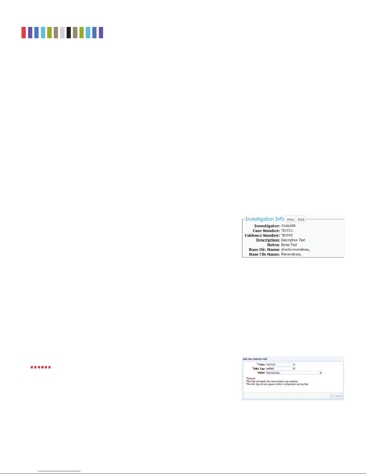
4.2 INVESTIGATION INFO
The Investigation Info panel groups related information that may also be used in
creating custom directories and fi le names (see Section 5.9). The “Hide” button allows
you to minimize the panel.
Click the Edit button to enter information about the Investigator, Case Number,
Evidence Number, Description, Notes, Base directory prefi x, and a Base fi lename prefi x
for a PCAP fi le.
Each fi eld is fi ltered to block non-printable ASCII characters. Any characters at the fi le
system level that may not be safe for a directory name or fi le name will be fi ltered out
and replaced with an underscore. Only printable ASCII characters are currently allowed
for directory and fi lenames. Multiple underscores will also be reduced to a single
underscore per naming item.
The Ditto Shark will generate an error message if you enter a non-printable ASCII char-
acter or if your message exceeds the 58 character limit. Additionally, when the fi nal
directory or fi lename that uses any of these fi elds is created, another level of fi ltering is
applied.
STOP!
Using apostrophes (‘) in the name fi elds will cause an error when the fi le or
folder name is created. They should not be used in the Investigation Info fi elds.
4.2.1 User Defi ned Fields
Click on the green plus sign icon to open the “Add User Defi ned Field” window
(see Figure 11). You may add as many user defi ned fi elds as you wish. Each user
defi ned fi eld must have a title, XML tag, and value.
Figure 9. The “Investigation Info” section.
Figure 11. The “Add User Defi ned Field” window.
Protecting Your Digital Assets
TM
Page 11
CRU Ditto Shark User Manual
11
The title identifies the value in the Ditto Shark’s browser and LCD interfaces, and
the XML tag only appears in the configuration and log files.
To remove a user defined field, click on the green minus sign icon.
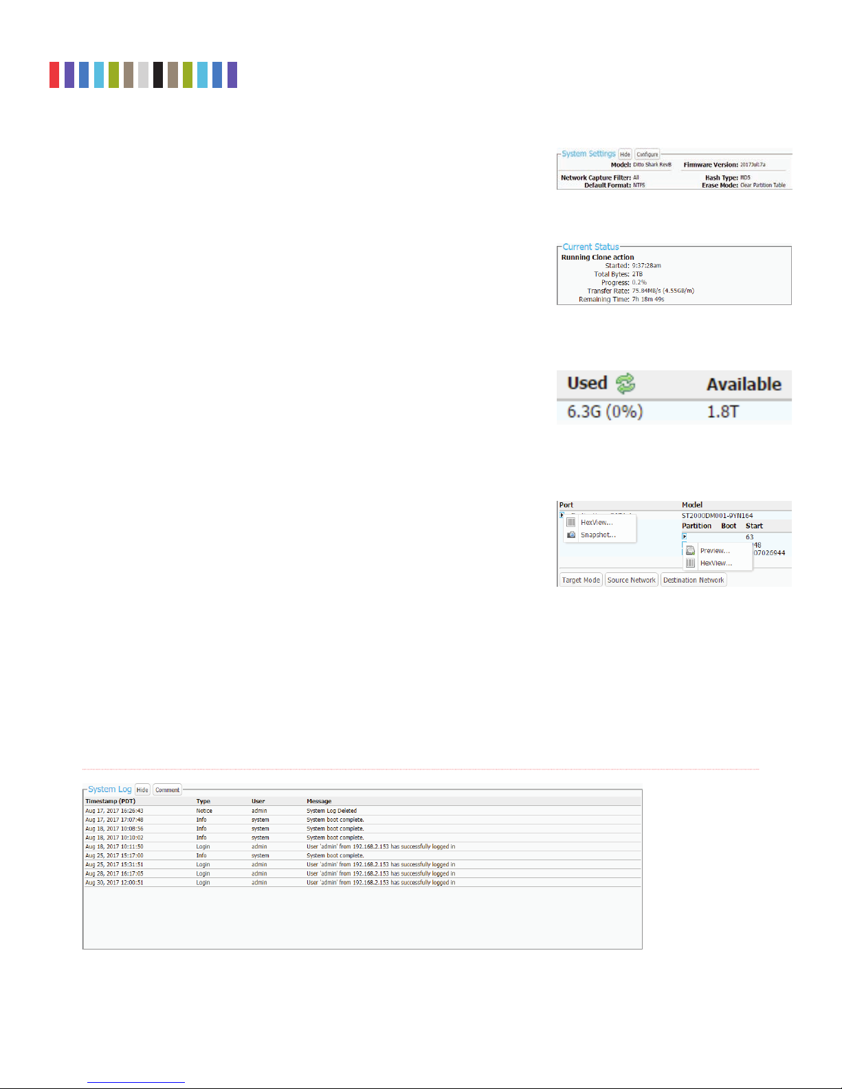
4.3 SYSTEM SETTINGS
Displays the most commonly used configuration settings of the Ditto Shark. These
settings are loaded as the default settings for the actions you perform in the “Action”
panel. The “Hide” button allows you to minimize the panel. Click the Configure
button to customize these settings as well as additional advanced settings. See Sec
-
tion 5.1 for details on each option.
4.4 CURRENT STATUS
Reports either as “Idle” or displays info about the action that the Ditto Shark is cur-
rently performing.
4.5 DISKS
Displays information about the attached media that are currently connected to the Ditto
Shark. The “Hide” button allows you to minimize the panel. To see the available space
a disk has, click the green double arrow icon next in the “Used” column header (see
Figure 14). The disk usage will refresh and give an updated amount.
The “Destination Network” button allows you to mount an iSCSI, NFS, or SMB share
to the Ditto Shark so that you can capture network data to it. For more information, see
Section 11.
4.5.1 View Hexidecimal Data
To view a disk’s hexidecimal data, click on the disk name under the “Port” column
and then select HexView. To view a disk partition’s hexidecimal data, click on the
partition’s number under the disk’s “Partition” column and then select HexView
(see Figure 15).
Figure 12. The “System Settings” section.
Figure 13. The “Current Status” section, displaying a
the status of a Physical Image action.
Figure 14. Clicking the green double arrow icon
displays and updates amount of space currently used
and available.
Figure 15. Drop-down menus for a disk (left) and a
disk’s partition (right).
4.5.2 View Snapshot Data
To view a disk’s snapshot information, click on the disk name under the “Port”
column and then select Snapshot.
Figure 16. The “System Logs” section on the “Home” screen.
Protecting Your Digital Assets
TM
Page 12

CRU Ditto Shark User Manual
12
4.6 SYSTEM LOG
Shows the actions that the Ditto Shark has performed (see Figure 16). The “Hide” button allows you to
minimize the panel. The “Comment” button allows you to write a note that is appended to the System log.
If there is no SD card present in the SD card slot, this panel displays the logs that have been stored in
volatile memory since the Ditto Shark’s last power cycle. These logs are deleted when the Ditto Shark is
powered down. If there is an SD card present, this panel displays all actions saved on the SD Card.
To view the log details of a particular action, click on the link under the “Message” column. which will be
denoted by a filename with a date/timestamp format: “S_yyyymmddhhmmss”. Alternatively, you can click
on the Logs button from the top menu bar.
5 CONFIGURE SCREEN
The “Configure” screen allows you to modify the way the Ditto Shark functions to suit your specific needs.
Click on the Configure tab to access the “Configure” screen from the Browser Interface.
5.1 SYSTEM
The “System” tab allows you to view and customize the following settings. This information is also dis-
played in the “System Settings” panel on the “Home” screen. When you are finished, click the Commit
Changes button to save the changes.
5.1.1 System Information
The “System Information” section displays the Ditto Shark’s model name and current firmware version.
5.1.2 Typical Settings
• Network Capture Filter: Sets the default network capture filter for the “Network Capture” action.
The available filters are All, HTTP, E-Mail, SSH, or any available custom filter that you have saved
onto the currently installed SD card. To create your own custom filter, see Section 11.3.
Figure 17. The “Configure” screen, showing the “System” tab.
Protecting Your Digital Assets
TM
Page 13

CRU Ditto Shark User Manual
13
• Default Format: Sets the default format for the “Erase Destination Disk” action. The available
format types are ext2, ext3, ext4, XFS, HFS+, FAT32, and NTFS.
• Hash Type: Sets the default hash algorithm that will be used for PCAP file verification. The avail
able algorithms are None, MD5, and SHA-1.
• Erase Mode: Sets the default erase mode for the “Erase Destination Disk” action. The available
options are Clear Partition Table and Quick Erase.
5.1.3 Advanced Settings
• Quick Start: Enables the “Quick Start” screen on the LCD that appears after you boot or reboot
the Ditto Shark. The settings for this mode may be modified in the “Quick Start” tab on the “Con
figure” Screen. See Section 5.6.
• Prompt Invest. Info: Opens a “Configure Investigation Info” window after the user has hit the
“Start” button in the “Action” panel on the “Home” screen. This allows the user to customize the
Investigator, Case Number, Evidence Number, Description, Notes, Base Directory Name, and the
Base File Name information prior to performing the requested action.
• LCD Prompt Case: Four options may be chosen to modify the case number specified in the
“Investigation Info” section of the “Home” screen. The case number is included in the log for the
requested action. “Disabled” leaves the case number as it is. “Inc/Dec” allows you to manually
increment the case number up or down using the navigation buttons on the face of the Ditto Shark.
“AutoInc” automatically increments the case number, and “AutoInc/Pause” automatically incre
ments the case number, but displays a confirmation prompt the LCD screen before beginning the
requested action. These options require a number to be present on the end of the Case Number
specified in the “Investigation Info” section.
-
-
-
• LCD Prompt Evidence: Four options may be chosen to modify the evidence number specified in
the “Investigation Info” section of the “Home” screen. The evidence number is included in the log
for the requested action. “Disabled” leaves the evidence number as it is. “Inc/Dec” allows you to
manually increment the evidence number up or down using the navigation buttons on the face of
the Ditto Shark. “AutoInc” automatically increments the evidence number, and “AutoInc/Pause”
automatically increments the evidence number, but displays a confirmation prompt the LCD screen
before beginning the requested action. These options require a number to be present on the end of
the Evidence Number specified in the “Investigation Info” section.
• LCD/LED Brightness: Sets the relative brightness of the LCDs and LEDs on the face of the Ditto
Shark on a scale of 0 to 6. Setting a value of “0” will turn off all LCDs and LEDs on the unit.
• Stealth Mode: Turns off all LEDs and LCDs on the Ditto Shark. The physical “Stealth Mode”
Switch serves the same purpose (see Section 1.2). If Stealth Mode is enabled from the Browser
Interface, the physical switch cannot override it.
• Audible Buzzer: Alerts the user to various actions that occur when using the Ditto Shark.
• Dual Destinations: Enables software mirroring mode to write the same data to two destinations at
the same time.
Protecting Your Digital Assets
TM
Page 14

CRU Ditto Shark User Manual
14
• Log Disk Info: Determines whether S.M.A.R.T. and hdparm disk information is logged before
running an action, after running an action, both, or not at all. CRU recommends that you log disk
information before and after an action.
• HTML Logging: Logs are always saved in XML format. This option causes the Ditto Shark to save
logs in HTML format as well.
• DiskView Logging: Logs any action to preview a disk (i.e. creating a disk snapshot, starting or
finishing a HexView action).
• Force SSL: When enabled, this setting forces any browser to use HTTPS to access the Ditto Shark
Browser Interface.
• PM Mirror Override: Overrides the Ditto Shark’s check that tells you whether two devices
attached to the Ditto Shark can be mirrored. In some cases, attached devices may not appear as
mirrorable to the Ditto Shark because of the way their firmware implements RAID or port-multi
plication (PM). This option gives you the ability to mirror any two devices you attach regardless of
these implementations. However, the attached devices must still be empty, so use the “Erase
Destination Disk” action from the “Home” screen if the devices are not empty (see Section 4.1.6)
before attempting to mirror them.
5.2 NETWORK
The “Network” tab allows you to view and customize the following settings. If you are unsure or have ques-
tions about changing your network settings, contact your network administrator. When you are finished,
click the Commit Changes button to save the changes.
-
5.2.1 Host Name
Allows you to change what name for the Ditto Shark will be displayed on a network. Host names are
not case sensitive, but must begin with any letter “A-Z”. They can contain the the letters A-Z, numbers
0-9, underscore “_”, and dash “-” characters. Host names must also be limited to 64 characters.
Figure 18. The “Network” tab on the “Configure” screen, showing the “Destination Network” and “Wifi
Network” settings. The “Wifi Network” section only appears when a USB wireless network adapter has been
plugged in.
Protecting Your Digital Assets
TM
Page 15

CRU Ditto Shark User Manual
15
5.2.2 Destination Network
The “Destination Network” section displays the destination Ethernet port’s MAC Address as well as its
network mode. You can enable or disable it using the check box.
To set the network mode, choose either “Server”, “Client (DHCP)”, or “Client (Static IP)” from the
drop-down box.
Server
“Server” allows you to configure the Ditto Shark for use as a server. This can be helpful if you are
connecting an iSCSI device to the destination Ethernet port, for example (see Section 11.1.2), or
you are connecting Ditto Shark directly to your computer instead of through your office network.
The default settings below will work for most environments. This is an advanced option, so do not
customize the default server configuration below unless directed to do so by your network adminis
trator.
See the Server settings on the next page.
IP Address: 10.10.10.1
Subnet Mask: 255.255.255.0
DHCP Server: Enabled
DHCP Start Address: 10.10.10.100
DHCP End Address: 10.10.10.199
DNS Server: Enabled
DNS Domain Name: ditto.local
NTP Server: Enabled
NAT Gateway: Disabled
-
STOP!
Do not connect the Ditto Shark to another network while it is configured as a server. Doing so will
cause network conflicts and may disrupt network traffic.
Client (DHCP)
This option automatically configures the destination Ethernet port to connect to the attached net-
work.
Client (Static IP)
This option allows you to manually configure the destination Ethernet port to connect to the attached
network.
5.2.3 Wifi Network
The “Wifi Network” section allows you to configure a third party USB wifi network adapter that’s been
plugged into the “NetTap Interface” USB port. You can enable or disable it using the check box.
This section also displays that port’s MAC Address. Adapters with an Atheros chipset and some
adapters with Realtek chipsets are compatible.
“Wifi Mode” allows you to determine whether the Ditto Shark connects to a wifi network or acts as
a wifi hot spot itself. Hot Spot Mode is helpful if you are working in a separate location from the Ditto
Shark that is still within range of a wireless network, or if there is no hardwired network available in the
location.
Protecting Your Digital Assets
TM
Page 16

CRU Ditto Shark User Manual
16
Choose “Client Mode” to connect to an existing wifi network or “Hot Spot Mode” to make the Ditto
Shark into a wifi hot spot.
Client Mode
Check “Status: Auto Start” if you want the Ditto Shark to connect to the specified wireless network
automatically.
To select the client mode’s networking mode, you can choose either “Client (DHCP)” or “Client
(Static IP) from the drop-down box underneath the MAC Address. “Client (DHCP)” automatically
configures the USB wifi network adapter to connect to a wifi network. “Client (Static IP)” allows you
to manually configure the connection.
Hot Spot Mode
Check “Status: Auto Start” if you want the Ditto Shark to begin broadcasting as a hot spot automati-
cally whenever a wifi adapter is plugged in.
The default settings below will work for most environments, with several exceptions.
STOP!
STOP!
STOP!
Input your own key to ensure that your Ditto Shark remains secure.
You may be required to conform to your country’s laws and regulations regarding wireless radio fre
quency usage. Select your two-digit country code from the “Regulatory Domain” drop down list, and
the Ditto Shark will limit the frequencies it may broadcast on to only those in the permitted range(s).
Do not connect the Ditto Shark to a wired network while it is configured as a hot spot. Doing so can
cause network conflicts and may disrupt network traffic.
SSID: {Host Name}-wifi
Regulatory Domain: Global
Band: G - 2.4 GHz
Channel: Auto
Broadcast: Checked
Security: WPA2 Personal
Key: ditto123
Show Key: Unchecked
IP Address: 10.10.10.1
Subnet Mask: 255.255.255.0
DHCP Server: Enabled
DHCP Start Address: 10.10.20.100
DHCP End Address: 10.10.20.199
DNS Server: Enabled
DNS Domain Name: dittowifi.local
NTP Server: Enabled
NAT Gateway: Disabled
-
Protecting Your Digital Assets
TM
Page 17

CRU Ditto Shark User Manual
17
Figure 19. The “Erase” tab on the “Confi gure” screen, showing the available erase modes and their customiz-
able settings.
5.3 ERASE
The Ditto Shark allows you to view and customize settings for how the Ditto Shark erases disks.
5.3.1 Available Erase Modes
ERASE MODE EXPLANATION
Clear Partition Table Removes the partition table on the disk.
Quick Erase Performs a single pass writing all zeroes.
5.3.2 Customizable Settings
Some Erase Modes require several of the following settings to be confi gured a certain way as part of
their standard. In these cases, the settings cannot be modifi ed.
• HPA/DCO Handling: Sets how erase actions using the specifi ed erase mode should handle HPAs
and DCOs. It can indicate in the log that there is an HPA (host protected area) or DCO (device con-
fi guration overlay) present, temporarily bypass the HPA, permanently unhide the HPA, or perma-
nently unhide both the HPA and DCO.
• Verify: This is a planned feature that is not currently implemented. The “Verify” drop-down box
will allow you to verify the erased disk after it has been fully erased. If “Quick” is selected, the
beginning, middle, and end of the disk will be read to ensure that the last pattern was actually
written. If “Full” is selected, the entire disk will be read to ensure that the last pattern was actually
written. If “None” is selected, no verifi cation will be performed.
• Format After Erase: Check this box to format the disk with the default format. The default format
can be set in the “System” tab on the “Confi gure” screen (see Section 5.1).
5.4 NETWORK CAPTURE
The “Network Capture” tab allows you to view and customize the following settings for all network capture
actions. When you are fi nished, click the Commit Changes button to save the changes.
5.4.1 Network Capture Settings
• Image File Count: Specifi es the maximum number of image fi les that are created on the destina-
tion disk. When the number is reached, the Ditto Shark will begin overwriting the oldest fi le on the
disk for each new fi le that is created. Set this to ‘0’ to fi ll the disk until it reaches capacity.
• Image File Segment Size: Allows you to specify the size in bytes that each image fi le should be.
The minimum size is 1M (megabyte). The maximum size is limited by the target fi le system. If this
fi eld is left blank, the maximum size will be used. When the specifi ed size is reached, a new image
fi le is created. Click the
Information icon for more information.
Protecting Your Digital Assets
TM
Page 18

CRU Ditto Shark User Manual
18
• Snap Size: Allows you to capture up to the specified amount of bytes of each packet of data.
• Dropped Pkt Log Interval: Allows you to specify the time interval in minutes of how often the
Ditto Shark writes its accumulated dropped packet information to the Action log. Setting this value
to ‘0’ disables packet loss reporting.
5.4.2 Live Capture Settings
When enabled, this service runs continuously in the background and streams captured data in realtime
over the network to a remote monitor using the third-party Wireshark network protocol analyzer. See
Section 4.1.1 for more information.
• Auto Start: Set this value to ‘Enabled’ to turn on live capture as soon as the Ditto Shark is pow
ered on. Set this value to ‘Disabled’ if you want the user to choose when to start the live capture
service in the Browser Interface.
• Port: This is the port that the Ditto Shark uses to talk to the third-party network protocol analyzer
software. The default port is 2002.
• Username: The username used by the third-party network protocol analyzer software.
• Password: The password used by the third-party network protocol analyzer software.
5.4.3 Advanced Settings
• Buffer Size: Sets the the buffer size used by the Ditto Shark during a network capture action. The
minimum size is 512K (kilobytes). The default size of 16M (megabyte) works best for most use
cases.
• MTU: If you are using the Ditto Shark on a network that’s configured to a non-standard maximum
transmission unit size (e.g. it uses jumbo frames), then set this field to match that value. Most
Ethernet LANs will use the standard MTU of 1500. The commonly accepted range for a valid MTU
is 68 to 65,535 as defined in RFC 791.
• Link Speed: Allows you to set the Ethernet connection speed throughput. In most cases, ‘Auto
Negotiate’ will work. If you experience problems staying connected, you may need to change the
speed to match what your network’s capabilities are.
-
Figure 20. The “Network Capture” tab on the “Configure” screen.
Protecting Your Digital Assets
TM
Page 19

CRU Ditto Shark User Manual
19
5.5 NAMING
The “Naming” tab allows you to customize how the Ditto Shark names directories
and files during imaging actions. When you are finished, click the Commit Changes
button to save the changes.
As shown in Figure 21, the file directory used in network capture actions can be a
name that contains up to six user-selectable fields, and the file name used in network
capture actions can contain up to four user-selectable fields. As you customize these
fields, the “Directory Name Template”, “Final Directory Name”, “File Name Tem
plate”, and “Final File Name” fields will update. The template fields show the order of
variables that will appear in the name, whereas the final name fields display the direc
tory or file name using the actual information from the “Investigation Info” panel on the
“Home” screen and the source disk.
5.9.1 Variables
To modify the any of the user-customizable variables, navigate to the “Investigation
Info” panel on the “Home” screen (see Section 4.2).
• Timestamp/{Timestamp}: Displays the timestamp. The timestamp is
required to be included in all directory names, but it is optional for file names.
-
-
• Base Filename: Displays the base file name. This option is the default first
variable for file names, but may be changed. User customizable.
• Case Number: Displays the case number. User customizable.
• Description: Displays the description field. User customizable.
• Evidence Number: Displays the evidence number. User customizable.
• Investigator: Displays the investigator. User customizable.
5.6 QUICK START
The “Quick Start” tab allows you to customize the quick start mode that appears on
the LCD of the Ditto Shark when the “Quick Start” option is enabled in the “System”
tab. Many of the settings on the next page are visible only when certain types of
actions are selected in the “Action to perform” drop-down box.
5.6.1 Quick Start Settings
• Action to perform: Sets the action that is performed by the quick start mode.
• Action Target: For the “Erase Destination Disk” action only. Specifies which
target volume will be erased.
Figure 21. The “Naming” tab on the “Configure”
screen.
Protecting Your Digital Assets
TM
Page 20

CRU Ditto Shark User Manual
20
6 ADMIN SCREEN
The “Admin” screen allows the administrator to manage user accounts and assign permis-
sion levels for each user. Click on the Admin tab to access the “Admin” screen from the
Browser Interface.
6.1 USER ACCOUNTS
The Ditto Shark contains two permanent accounts; “admin” and “panel”. The “admin”
account is the Administrator account, and only the Full Name and password may be
modified. The “panel” account is the Front Panel account, and modifies access permis
sions for functionality that can be accessed through the LCD screen and navigation
buttons on the Ditto Shark.
6.2 PERMISSIONS
6.2.1 Permission Levels
Permission levels on the Browser Interface are displayed as “FULL”, “AUTH”, or as a hyphen, and
when editing or creating a user they are displayed as “Full Access, “Must Authenticate”, and “None”,
respectively. “FULL” and “Full Access” indicate that the user has complete access to the features
governed by that permission and is not required to enter a password. “AUTH” and “Must Authenticate”
indicate that the user must authenticate his credentials with a password in order to change a setting or
perform an action that that permission governs. A hyphen or “None” indicates that the user does not
have access to the features governed by that permission.
-
Figure 22. The “Admin” screen.
6.2.2 Configurable Permissions
The following list of permissions specifies what each controls, and can be configured when adding or
editing a user account. Some permissions for the Administrator and Front Panel accounts will be greyed
out by default.
• Admin: “None” allows access to modify the User Name and Full Name of the Administrator, Front
Panel, and the user’s own account, and allows the user to change his or her own password, but
blocks the user from viewing any account’s permission levels. “Modify Users” enables the user to
be able to modify user accounts, passwords, and permissions (except for the “Admin” permission).
“Full Access” additionally enables the ability to create and delete users and assign the “Admin”
permission.
• Config: Governs all non-network configuration settings, including those found in the “System Set
tings” panel on the “Home” screen and on all tabs on the “Configure” screen.
• NetSettings: Controls access to the network settings on the “Configure” screen.
• Erase: Controls access to the “Erase Destination Disk” action.
• Network Capture: Controls access to the “Network Capture” action.
• Abort: Controls access to the ability to abort actions in progress.
• Note: Controls access to the “Comment” buttons in the “Action” and “System Log” panels on the
“Home” screen.
-
Protecting Your Digital Assets
TM
Page 21

CRU Ditto Shark User Manual
21
• Logs: Controls the ability to delete log fi les from the “Logs” screen.
• DiskView: Controls the ability to HexView and Snapshot media via the “Disks” panel on the
“Home” screen.
6.3 ADDING A NEW USER
To add a new user, click the Add User button, enter the user’s information, and set the permission levels.
When fi nished, click on the Commit Add button.
6.4 EDITING AN EXISTING USER
To update a user’s name, password, or permissions, click on the user account under the “User Name”
column, update the information, and then click the Commit Edits button.
6.5 DELETING A USER
To delete a user, click on the user account under the “User Name” column and click on the Delete User
button. Do not click this button unless you are absolutely certain you wish to delete the account.
7 LOGS SCREEN
The “Logs” screen provides information about the Ditto Shark’s actions. Click on the Logs tab to access the
“Logs” screen from the Browser Interface.
Action logs show the timestamp, the type of action performed, the user who performed the action, and a link to
the “Action Log” screen that provides more information about the performed action. Click on that link to view
that information.
7.1 DELETE LOG
Check the box next to each log fi le you wish to delete. To delete the system log, check the box next to
“System Log” at the bottom of the Logs tab. Then click the Delete button. Finally click the Yes button on
the dialog box that pops up to delete the checked logs.
7.2 SAVE LOG
Check the box next to each log fi le you wish to save to your local computer system. To save the system log,
check the box next to “System Log” at the bottom of the Logs tab. Then click the Save button. The “Save
Figure 23. The “Logs” screen.
Protecting Your Digital Assets
TM
Page 22

CRU Ditto Shark User Manual
22
Logs” dialog box will pop up. Name the log file and choose whether to save it in XML or HTML format.
Then click the Submit button. The “Save As” dialog box will pop up. Choose where on your system to
save the file, then click Save.
8 UTILITIES SCREEN
The “Utilities” screen allows you to perform various miscellaneous functions, including the ability to upgrade
firmware, remotely reboot the Ditto Shark, modify date and time settings, perform a factory reset, and import
customized configurations. Click on the Utilities tab to access the “Utilities” screen from the Browser Inter
face.
8.1 SYSTEM MAINTENANCE
8.1.1 Firmware Upgrade
For information on how to upgrade the firmware, see Section 12.
8.1.2 Configuration
You can save and load configurations for the Ditto Shark. The file generated saves a copy of every cus-
tomizable setting for the unit.
Save Configuration
To save a configuration, click on the Save Config button. Name the file, and then click Continue to
open a Save As dialog box and save the file to your computer.
-
Load Configuration
a. Click on the Load Config button, browse to the XML configuration file you want to load, high-
light it, and click Open.
b. The “Confirm Import” window will open. Place a check next to each setting you want to load,
and then click Continue. By selecting these settings, you will be overwriting the existing set
tings, so be sure to save the current configuration first.
c. The Ditto Shark will import the configuration settings. Click OK when it’s finished.
-
8.1.3 Other Buttons
• Reboot: Opens a confirmation to reboot the Ditto Shark.
• Date & Time: Allows you to set the current date, time, and timezone. Click the Synchronize button
to sync these settings with your browser’s operating system.
Figure 24. The “Utilities” screen.
Protecting Your Digital Assets
TM
Page 23

CRU Ditto Shark User Manual
23
• Factory Reset: Opens a confirmation dialog to return the Ditto Shark to factory settings. Check the
Purge Ditto SD card log files box to remove all log files from the SD card in the unit. You can also
use the Front Panel to perform a factory reset. See Section 9.3.
• System Verify: Verifies that the Ditto Shark’s operating system files have not been modified and
places a statement in the system log. If the verification fails, the details can be viewed by exporting
the System Diagnostics.
• Diagnostics: Exports a diagnostics log file in HTML format. The diagnostics log contains informa
tion about the Ditto Shark’s current configuration, including user accounts, kernel messages, logs,
process information, connected disks, PHP errors, and system verify results.
-
8.2 UPGRADE LOG MESSAGES
This section displays the status log of firmware upgrades and is only visible after a firmware upgrade has
been performed.
8.3 IMPORT LOG MESSAGES
This section displays the status log of configuration file exports and imports and is only visible after a con-
figuration file has been loaded.
9 USING THE FRONT PANEL INTERFACE IN STANDALONE MODE
The Ditto Shark can work as a standalone device with no additional computer required, which can be useful
when targeting network traffic in the field.
The Front Panel interface allows you to perform a network capture or erase a disk. You can also adjust settings,
view information about attached media, or check on the Ditto Shark’s operational status. The administrator
account can assign access permissions to the Front Panel’s actions and settings using the Browser Interface.
9.1 HOW TO NAVIGATE
9.1.1 Using the Navigation Buttons
The navigation buttons on the front of the Ditto Shark allow you to navigate through the menu. Up
and Down allow you to scroll through the available options on the Front Panel, while Enter selects the
option and Back goes back to the previous screen. If Quick Start Mode is enabled, press Back to exit it.
9.1.2 Using a Keyboard
Plug a PC USB keyboard into a USB port on the “NetTap Interface” side of the Ditto Shark. You can
navigate using the arrow keys. Press Enter arrow keys to select a menu option. Press the Left Arrow
key to back out of a menu or setting. If Quick Start Mode is enabled, you can press the Escape key to
exit it.
9.2 MENU SCREENS
The Ditto Shark menu consists of the following screens:
9.2.1 Status
The status screen is the default screen. It shows the progress of any current
processes. When the Ditto Shark is “Idle”, the current firmware of the unit is also
listed on this screen. An example of a status screen is shown in Figure 25.
Protecting Your Digital Assets
TM
ditto-####: Idle
Version: 2017Jul17a
2017Aug31 3:58:35pm
(Up/Dn for Menu)
Figure 25. The “Status” screen on the Front Panel
LCD.
Page 24

CRU Ditto Shark User Manual
24
9.2.2 Perform Action
After you adjust settings to your specifications, you are ready to put the Ditto Shark to work. The “Per-
form Action” screen lets you start or abort any of the Ditto Shark’s actions using the current settings.
a. On the “Perform Action” screen, use the Up and Down buttons to cycle through the available
actions. Press Enter to select the one you want.
b. Cycle through the available settings for the action. Press Enter if you wish to modify them.
c. When you are finished modifying settings, scroll down to option that asks you to start the action (ex.
“Start Network Capture?”. Press Enter to begin.
The status and remaining time will be displayed on the LCD screen as the Ditto Shark performs the
action. To abort an action, press Back. The LCD screen will ask if you wish to abort the action. Press
Enter to confirm, or Back to cancel the abort request.
9.2.3 Investigation Info
The “Investigation Info” lists the current settings that can be modified in the
“Investigation Info” section on the “Home” screen of the Browser Interface. To
modify these settings from the Browser Interface, see Section 4.2.
Editing Fields With A Keyboard
On the “Investigation Info” menu, an “Edit (Keyboard)” menu item will appear
when a keyboard is detected (see Figure 26). You can edit the field currently
displayed on the LCD by pressing the Enter button on the face of the Ditto
Shark or by pressing Enter or the Right Arrow keys on the keyboard, and then
using the keys to type.
Figure 26. The “Investigator” field in the “Investiga-
tion Info” menu on the Front Panel LCD, when a USB
keyboard is attached to the Ditto Shark.
Investigator:
C. Walker
Edit (Keyboard)
STOP!
NOTE
NOTE
Using apostrophes (‘) in the name fields will cause an error when the file or folder name is created.
They should not be used in the Investigation Info fields.
Text strings longer than 20 characters are displayed with an ellipses character (...) at the right side of
the string.
The Ditto Shark can handle multiple USB devices through a USB hub attached to the USB port on the
“NetTap Interface” side of the Ditto Shark. However, if multiple keyboards are connected, keystrokes
from all keyboards are processed.
Here is a table of the most common keyboard commands:
KEY COMMAND
Escape Cancels an edit.
Enter Begins an edit on a user-editable string or selects the currently-visible
menu option. When pressed while editing a string, it confirms the edit.
Home/End When editing a string, these keys move the cursor to the beginning/end
of the string, respectively.
Up/Down Moves through the menu options. When editing a string, they move the
cursor to the beginning/end of the string, respectively.
Delete Deletes the character currently highlighted by the cursor.
More commands are detailed on the next page.
Protecting Your Digital Assets
TM
Page 25

CRU Ditto Shark User Manual
25
Keyboard Commands, continued...
KEY COMMAND
Backspace Deletes the character immediately behind the cursor.
NumLock Forces the numbered arrow keys to type numbers when pressed.
CapsLock Forces all letter keys to type capital letters.
Tab/Shift+Tab/Page Up/
Page Down/Function/Alt/
Windows/Control/Insert
Not handled.
9.2.4 Settings
The “Settings” screen allows you to view and customize the following settings, which are grouped into
three subsections. These settings will be the default settings used in any actions performed.
NOTE
The System Settings below cannot be modified if the Front Panel user account does not have full
access to the “Config” permission, and the Dst Network Settings cannot be modified if the Front
Panel user account does not have access to the “NetSettings” permission. See Section 6 for informa
tion on how to customize the Front Panel user account.
System Settings
• Default Format: Sets the default format for the “Erase Destination Disk” action. The available
format types are ext2, ext3, ext4, XFS, HFS+, FAT32, and NTFS.
• Hash Type: Sets the default hash algorithm that will be used for PCAP file verification. The
available algorithms are None, MD5, and SHA-1.
• Erase Mode: Sets the default erase mode for the “Erase Destination Disk” action. The avail
-
able options are “Clear Part..ion Table” (Clear Partition Table) and Quick Erase.
• Quick Start: Enables the “Quick Start” screen on the LCD that appears after you boot or
reboot the Ditto Shark. The settings for this mode may be modified in the “Quick Start” tab on
the “Configure” Screen within the Browser Interface. See Section 5.6.
• Prompt Invest. Info: This opens a “Configure Investigation Info” window within the Browser
Interface after the user has begun an action from the Browser Interface. This allows the user to
customize the Investigator, Case Number, Evidence Number, Description, Notes, Base Direc
-
tory Name, and the Base File Name information prior to performing the requested action.
• Prompt Case: Four options may be chosen to modify the case number specified in the “Inves
tigation Info” section of the “Home” screen in the Browser Interface. The case number is
included in the log for the requested action. “Disabled” leaves the case number as it is. “Inc/
Dec” allows you to manually increment the case number up or down using the navigation
buttons on the face of the Ditto Shark. “AutoInc” automatically increments the case number,
and “AutoInc/Pause” automatically increments the case number, but displays a confirmation
prompt the LCD screen before beginning the requested action. These options require a number
to be present on the end of the Case Number specified in the “Investigation Info” section of
the “Home” screen within the Browser Interface.
-
-
• Prompt Evidence: Four options may be chosen to modify the evidence number specified in
the “Investigation Info” section of the “Home” screen. The evidence number is included in the
Protecting Your Digital Assets
TM
Page 26

CRU Ditto Shark User Manual
26
log for the requested action. “Disabled” leaves the evidence number as it is. “Inc/Dec” allows
you to manually increment the evidence number up or down using the navigation buttons on
the face of the Ditto Shark. “AutoInc” automatically increments the evidence number, and
“AutoInc/Pause” automatically increments the evidence number, but displays a confirmation
prompt the LCD screen before beginning the requested action. These options require a number
to be present on the end of the Evidence Number specified in the “Investigation Info” section
of the “Home” screen within the Browser Interface.
• LCD/LED Brightness: Sets the relative brightness of the LCDs and LEDs on the face of the
Ditto Shark on a scale of 0 to 6. Setting a value of “0” will turn off all LCDs and LEDs on the
unit.
• Buzzer: Alerts the user to various actions that occur when using the Ditto Shark.
• Dual Destinations: Enables software mirroring mode to write the same data to two destina
-
tions at the same time.
• Log Disk Info: Determines whether S.M.A.R.T. and hdparm disk information is logged before
running an action, after running an action, both, or not at all. CRU recommends that you log disk
information before and after an action.
• HTML Logging: Logs are always saved in XML format. This option causes the Ditto Shark to
save logs in HTML format as well.
• DiskView Logging: Logs any action to preview a disk (i.e. creating a disk snapshot, starting or
finishing a HexView action).
• Force SSL: When enabled, this setting forces any browser to use HTTPS to access the Ditto
Shark Browser Interface.
• Stealth Mode: Turns off all LEDs and LCDs on the Ditto Shark. The physical “Stealth Mode”
Switch serves the same purpose (see Section #.#). If Stealth Mode is enabled from the
Browser Interface, the physical switch cannot override it.
• PM Mirror Override: Overrides the Ditto Shark’s check that tells you whether two devices
attached to the Ditto Shark can be mirrored. In some cases, attached devices may not appear
as mirrorable to the Ditto Shark because of the way their firmware implements RAID or
port-multiplication (PM). This option gives you the ability to mirror any two devices you attach
regardless of these implementations. However, the attached devices must still be empty, so
use the “Erase Destination Disk” action from the “Home” screen if the devices are not empty
(see Section 4.1.6) before attempting to mirror them.
NetCap Settings
This section allows you to modify the settings that govern network capture actions.
• NetCap Filter: Sets the default network capture filter for the “Network Capture” action. The
available filters are All, HTTP, E-Mail, SSH, or any available custom filter that you have saved
onto the currently installed SD card. To create your own custom filter, see Section 11.3.
• NetCap File Count: Specifies the maximum number of image files (based on image file seg
ment size, see Section 5.4.1) that are created on the destination disk. When the number is
Protecting Your Digital Assets
TM
-
Page 27

CRU Ditto Shark User Manual
27
reached, the Ditto Shark will begin overwriting the oldest file on the disk for each new file that
is created. Set this to ‘0’ to fill the disk until it reaches capacity.
• NetCap Snap Size: Allows you to capture up to the specified amount of bytes of each packet
of data.
• NetCap Pkt Log Inter: Allows you to specify the time interval in minutes of how often the Ditto
Shark writes its accumulated dropped packet information to the Action log. Setting this value to
‘0’ disables packet loss reporting.
• Live Capture: This service runs continuously in the background and streams captured data in
realtime over the network to a remote monitor using the third-party Wireshark network protocol
analyzer. See Section 4.1.1 for more information.
• LiveCap Auto Start: Set this value to ‘Enabled’ to turn on live capture as soon as the Ditto
Shark is powered on. Set this value to ‘Disabled’ if you want the user to choose when to start
the live capture service in the Browser Interface.
• NetCap MTU: If you are using the Ditto Shark on a network that’s configured to a non-standard
maximum transmission unit size (e.g. it uses jumbo frames), then set this field to match that
value. Most Ethernet LANs will use the standard MTU of 1500. The commonly accepted range
for a valid MTU is 68 to 65,535 as defined in RFC 791.
• NetCap Link Speed: Allows you to set the Ethernet connection speed throughput. In most
cases, ‘Auto Negotiate’ will work. If you experience problems staying connected, you may need
to change the speed to match what your network’s capabilities are.
Dst (Destination) Network Settings
This section allows you to modify the settings for the network connection on the “Destination Inter-
face” side of the Ditto Shark, which is used to connect to the Browser Interface.
• Dst Network: Enable or disable the destination network Ethernet connection.
• Dst MAC Address: Displays the destination Ethernet port’s MAC address.
• Dst Network Mode: Displays the destination Ethernet port’s networking mode. The available
options are Server, Client (DHCP), or Client (Static IP). “Server” allows you to connect the Ditto
Shark directly to a computer without the use of an intermediary network. The network mode
can be further configured in the Browser Interface (see Section 5.2.2).
• Dst IP Address: Displays the IP address assigned to the destination Ethernet port.
• Dst Subnet Mask: Displays the subnet mask address assigned to the destination Ethernet
port. It is only visible if “Dst Network Mode” is set to “Client (Static IP)” or “Server”.
Date & Time
• Date: Displays the date.
• Time: Displays the time.
• Timezone: Displays the time zone.
Protecting Your Digital Assets
TM
Page 28

CRU Ditto Shark User Manual
28
9.2.5 Disk Info
The “Disk Info” screen (Figure 27) shows all available disks attached to either the
source or destination ports. Ports are shown only if a disk is connected there. Press
Enter and then Up or Down to scroll through the following information about each
connected disk:
Destination DataPort:
Hitachi HT...232A7A384
320.1GB NTFS
Details >
• Connected port on the Ditto Shark
• Used disk capacity
• Available disk capacity
• File system
Figure 27. The “Disk Info” screen on the Front Panel
LCD.
9.3 FACTORY RESET
To reset the Ditto Shark’s settings back to their factory defaults, press and hold the
Up, Enter, and Down navigation buttons while powering the unit on. The Ditto Shark
will start up and then display the text, “Initializing... Prep Factory Reset” (see Figure
28).
You will then be prompted to confirm your choice to reset the Ditto Shark. Press Enter
to continue or Back to cancel.
You can also use the Browser Interface to perform a factory reset. See Section 8.1.3.
Figure 28. The “Preparing Factory Reset” screen on
the Front Panel LCD.
10 STEALTH MODE
Stealth Mode turns off all LEDs and LCDs on the Ditto Shark. You can enable Stealth Mode by flipping the
physical Stealth Mode switch on the “Destination Interface” side of the Ditto Shark (see Section 1.2).
You can also enable it from the Browser Interface. Click on the Configure tab, and then under the “System”
tab change the “Stealth Mode” drop-down box to Enabled. Then click Commit Changes.
NOTE
If Stealth Mode is enabled from the Browser Interface, the physical switch cannot override it.
****DITTO****
Initializing...
Preparing Factory Reset
11 ADVANCED FEATURES AND FUNCTIONS
11.1 USING ISCSI DEVICES
11.1.1 Remotely Access an iSCSI Device
To connect to an iSCSI device that exists on your network, follow these directions.
a. Ensure that the Ethernet port through which the Ditto Shark is connected to your network is properly
configured for use with your network (see Section 5.2). Unless you have manually configured the
Ditto Shark’s network settings before, you most likely do not have to change anything. If you are
directly connecting the iSCSI device to the Ditto Shark, then see Section 11.1.2.
b. On the “Home” Screen, navigate down to the bottom of the “Disks” panel.
c. Click the Destination Network button to attach the iSCSI device as a read/write-enabled destina
tion.
d. Click on the iSCSI tab if it is not already selected.
e. Type the iSCSI device’s IP address into the “Target Host” text field.
Protecting Your Digital Assets
TM
-
Page 29

CRU Ditto Shark User Manual
29
f. Type in the port number of the target iSCSI volume into the “Port” text field if the number is dif-
ferent than the default value of ‘3260’. If you don’t know the port number, leave it as the default
value.
g. Click the Discover button. The Ditto Shark will detect any IQNs (iSCSI Qualified Names) attached to
the IP address.
h. Select the IQN you wish to attach to the Ditto Shark from the drop-down box.
i. If authentication is required to connect to the IQN, click the Advanced... button and input the appro
priate credentials, including the user name, password, and domain. Otherwise, continue to Step J.
j. Click the Add button. The IQN will now appear in the list below.
k. Repeat steps E through J to add more IQNs. When you are finished, click Close.
The iSCSI disk(s) have now been added to the list of Disks, allowing you to perform actions on them like
you would any other disk.
11.1.2 Directly Connect an iSCSI Device to the Ditto Shark
First, ensure that the destination Ethernet port is configured to act as a server. If it
already is, begin at Step D.
a. Click on the Configure tab at the top of the page, and then select the Network
tab.
b. In the “Destination Network” section, select Server from the drop-down box
underneath the MAC address. Do not customize the default server configura
tion unless directed to do so by your network administrator.
c. Click Commit Changes.
d. Now connect the iSCSI Device to the Ethernet port on the “Destination
Interface” side of the Ditto Shark. The iSCSI device will be assigned a new
IP address if the iSCSI device is configured to obtain a new IP address from
DHCP, which will the case for most devices. If no IP address is assigned, you will need to configure
the iSCSI device to use DHCP. If that is not possible, contact your network administrator.
-
Figure 29. The “Destination Network” section on the
“Configure” screen’s “Network” tab.
-
e. Go back to the “Home” Screen and click the Destination Network button at the bottom of the
“Disks” panel.
f. On the window that pops up, click on the iSCSI tab if it is not already selected.
g. Type the iSCSI device’s IP address into the “Target Host” text field.
h. Type in the port number of the target iSCSI volume into the “Port” text field if the number is dif
ferent than the default value of ‘3260’. If you don’t know the port number, leave it as the default
value.
i. Click the Discover button. The Ditto Shark will detect any IQNs (iSCSI Qualified Names) attached to
the IP address.
j. Select the IQN you wish to attach to the Ditto Shark from the drop-down box.
Protecting Your Digital Assets
TM
-
Page 30

CRU Ditto Shark User Manual
30
k. If authentication is required to connect to the IQN, click the Advanced... button and input the
appropriate credentials, including the user name, password, and domain. Otherwise, continue to the
next step.
l. Click the Add button. The IQN will now appear in the list below.
m. Repeat steps G through L to add more IQNs. When you are finished, click Close.
The iSCSI disk(s) have now been added to the list of Disks, allowing you to use the Ditto Shark to per
form actions on them like you would any other disk.
11.1.2 Properly Remove an iSCSI Device
This process prevents timeout issues where the Ditto Shark will attempt to connect to iSCSI volumes
that no longer are connected to it. On the “Home” Screen, navigate down to the bottom of the “Disks”
panel.
a. Click the Destination Network button.
b. Click on the iSCSI tab if it is not already selected.
c. Under the “iSCSI Source Connections” or the “iSCSI Destination Connections” section, check the
boxes next to the IQN(s) you want to remove and click the Remove button.
d. Physically disconnect the iSCSI device from the Ditto Shark.
11.2 USING NFS AND SMB (SAMBA) SHARES
11.2.1 Connect to NFS and SMB Shares
a. Connect the Ditto Shark to the network that your NFS or SMB share exists on through the “Destina-
tion Interface” side of the Ditto Shark.
b. On the “Home” Screen, click the Destination Network button at the bottom of the “Disks” panel.
c. Click on the NFS tab or the SMB tab, depending on which type of share you are connecting to.
-
d. Type the server name into the Server text field.
e. If you are connecting to an SMB share, select the appropriate protocol from the “Protocol” drop-
down box. If you don’t know the correct protocol, leave it as the default value of ‘SMBv1’.
f. Click the Show Shares button. The Ditto Shark will detect any shares attached to the server.
g. Select the share you wish to attach to the Ditto Shark from the drop-down box.
h. If you are connecting to an SMB share and authentication is required, click the Advanced... button
and input the appropriate credentials, including the user name, password, and domain. If the SMB
share does not require authentication or you are connecting to an NFS share, continue to the next
step.
i. Click the Add button. The share will now appear in the list below.
j. Repeat steps C through I to add more shares. When you are finished, click Close.
The share(s) have now been added to the list of Disks, allowing you to perform actions on them like you
would any other disk.
Protecting Your Digital Assets
TM
Page 31

CRU Ditto Shark User Manual
31
11.2.2 Remove an NFS or SMB (Samba) Share
a. On the “Home” Screen, click the Destination Network button at the bottom of the “Disks” panel.
b. Click on the NFS tab or SMB tab, depending on the which type of share you are removing.
c. Check the boxes next to the share(s) you want to remove and then click the Remove button.
11.3 USING AND CONFIGURING NETWORK CAPTURE FILTERS
Insert the SD Card containing your network capture fi lter(s) into the Ditto Shark and your custom network
capture fi lters will then be available in the “Network Capture Filter” drop-down box when confi guring a
“Network Capture” action. You may also add subdirectories that contain one or more network capture fi lter
XML fi les to the DittoNetCapFilter directory.
To add or edit your own network capture fi lter, choose the way that works best for your usage scenario.
11.3.1 Filter Creation Via Web Browser
a. Insert the SD Card into the SDCard slot on the rear of the Ditto Shark.
b. Using the Browser Interface, select Network Capture from the “Action to Perform” drop-down
box.
c. If you are editing an existing network capture fi lter that you created, select it from the “Network
Capture Filter” drop-down box.
d. Type in the ports you wish to capture in your network capture fi lter in the text box directly below the
“Network Capture Filter” drop-down box (see Figure 30). Use the word ‘or’ to separate each port.
e. Click the Save button. The “Save Network Capture Filter” dialog box will pop up (see Figure 31).
f. Use the “Select Filter...” drop-down box and select New Filter... to create a new fi lter or select an
existing fi lter to overwrite it.
g. Use the “Select File...” drop-down box and select New File... to create a new XML fi le, or select an
existing fi le to add your network capture fi lter to the fi le.
h. Type the desired fi lename into the “File Name” text box.
i. Type the desired name of the fi lter into the “Filter Name” text box.
j. Click the Save button to save the fi lter.
Figure 30. The “Action” screen, showing where to type in the
ports that you wish to capture with the “Network Capture”
action.
Protecting Your Digital Assets
TM
Figure 31. The “Save Network Capture Filter”
dialog box lets you save custom network
capture fi lters.
Page 32

CRU Ditto Shark User Manual
32
11.3.2 Manual Filter Creation
To manually create a network capture fi lter on an SD Card, you must manually create a DittoNetCap-
Filter directory on your SDCard fi rst. Then you can add one or more network capture fi lter XML fi les to
that directory.
Create an XML fi le using the following structure and place it within the DittoNetCapFilter directory on
your SDCard:
<?xml version=”1.0” encoding=”UTF-8”?>
<!-- All attributes must be in single quotes if they contain double quotes.
-->
<dittoNetCapFilter
xmlns:xsi=”http://www.w3.org/2001/XMLSchema-instance”
xsi:noNamespaceSchemaLocation=”netCapFilter.xsd”
>
<fi lter title=”All”>insert port numbers here, separated by the word‘or’</
fi lter>
</dittoNetCapFilter>
The name of the network capture fi lter XML fi le can be any legal fi le name with an XML fi le extension.
Each XML fi le may contain one or more <fi lter title=”...”> blocks. The fi lter block’s title will appear at
the bottom of the “Network Capture Filter” selection list prepended with “SDCard/” followed by the
subdirectory’s name, if any.
NOTE
You cannot remove existing selections from the Network Capture Filter list.
To download an XML Schema that can be used to validate your network capture fi lter XML fi le, type
the following into the address bar of an Internet browser, where <IP Address> is the IP address of your
Ditto Shark: http://<IP Address>/data/DittoNetCapFilter/netCapFilter.xsd
Click the
fi lters.
Information icon for a link to a site that describes the syntax supported by network capture
12 UPGRADING FIRMWARE
There are three methods to upgrade your Ditto Shark’s fi rmware. Firmware upgrades are made available on
CRU’s website at www.cru-inc.com/support/software-downloads/Ditto-Shark-fi rmware-updates/.
METHOD 1: COPY AND PASTE A LINK
a. Ensure that the Ditto Shark is connected to a network with Internet access.
b. Go to the fi rmware updates webpage and scroll down to the “Ditto Shark Firmware Links” section.
Copy the URL of the fi rmware you wish to use to upgrade.
c. Log into your Ditto Shark’s Browser Interface and navigate to the “Utilities” screen.
d. Paste the link into the top text fi eld and click the Firmware Upgrade button.
e. When it asks you to confi rm the retrieval of the upgrade fi le, click Continue.
Protecting Your Digital Assets
TM
Page 33

CRU Ditto Shark User Manual
33
f. The Ditto Shark will download the file to itself. Once downloaded, it will ask you to confirm the upgrade.
Click Continue. After the upgrade is finished, click OK.
g. The LCD panel of the Ditto Shark will ask you to reboot. Press the Enter button on the face of the unit
to reboot, or click on the Reboot button on the “Utilities” screen.
METHOD 2: DOWNLOAD TO YOUR COMPUTER
a. Go to the firmware updates webpage and scroll down to the “Ditto Shark Firmware Links” section.
b. Click on the firmware you wish to use to upgrade to download the file. Save the file in a convenient
location.
c. Log into your Ditto Shark’s Browser Interface, navigate to the “Utilities” screen, and click on the top
Upload... button.
d. Locate the firmware file you just downloaded, select it, and click Open.
e. Click on the Firmware Upgrade button.
f. The Ditto Shark will upload the file to itself. Once uploaded, it will ask you to confirm the upgrade. Click
Continue. After the upgrade is finished, cick OK.
g. The LCD panel of the Ditto Shark will ask you to reboot. Press the Enter button on the face of the unit
to reboot, or click on the Reboot button on the “Utilities” screen.
METHOD 3: UPLOAD VIA A USB THUMB DRIVE
a. Go to the firmware updates webspage and scroll down to the “Ditto Shark Firmware Links” section.
b. Click on the firmware you wish to use to upgrade to download the file. Save the file to a USB thumb
drive.
c. Insert the thumb drive into the “NetTap Interface” side USB port of the Ditto Shark.
d. The Ditto Shark will immediately scan the thumb drive and display a list on the LCD screen of all firm
ware files found on the drive. Use the navigation buttons on the face of the unit to move the blinking
cursor to the firmware that you wish to use to upgrade, and then press Enter.
e. The Ditto Shark’s firmware will be upgraded. The LCD panel of the Ditto Shark will ask you to reboot.
Press Enter to reboot.
-
Protecting Your Digital Assets
TM
Page 34

CRU Ditto Shark User Manual
34
13 TECHNICAL SPECIFICATIONS
Product Name Ditto Shark
1000BASE-T EtherNet: up to 1 Gbps
Data Interface Types &
Speeds
Supported Drive Types 2.5 and 3.5-inch SATA HDDs and SSDs
DataPort DP20 Drive Support 2.5-inch SATA HDDs and SSDs
DataPort DP20: up to 6 Gbps
eSATA: up to 6 Gbps
UHS-III SD Card: up to 624 MB/s
USB 2.0: up to 480 Mbps
SD Card Slot Support
Wifi USB Adapter Support Wifi adapters with Atheros chipsets, and some Realtek chipsets
DP20 Carrier Torque 2.5-inch drives, M3 screws: 4 inch-pounds max.
Data Connectors
Supported File Systems ext2, ext3, ext4, FAT32, HFS+, NTFS, XFS
User Interface
Stealth Mode Turns off all lights (LEDs/LCD)
Browser Compatibility Chrome, Edge, Firefox, Opera, Safari
Hash Modes None, MD5, SHA-1
MMC, SD, SDHC, SDXC, UHS-I, UHS-II, UHS-III (mini- and micro- card types
are compatible with adapters)
Two (2) eSATA ports
Three (3) 1000BASE-T Ethernet connectors
One (1) USB 2.0 connectors
One (1) SD Card slot
Four-line LCD controlled with four soft-touch menu navigation buttons or USB
keyboard
Browser-based Ditto interface allows for direct operation, remote operation, and
administration
Erase Modes Clear Partition Table, Quick Erase
External material All-metal construction
Operating Humidity 5% to 95%, non-condensing
Power Switch 2 position: On / Off
Power Input 40W 12V 3.33A DC barrel connector (center pin positive)
Power over Ethernet PoE+ (30W)
EMI Standard: FCC Part 15 Class A
Compliance
Product Weight
EMC Standard: EN55024, EN55032
CE, RoHS
Unpopulated: 2.91 pounds (1.32 kg)
Populated: 3.16 pounds (1.43 kg)
Product Dimensions 5.63in W x 9.00in L x 1.62in H (143mm W x 229mm L x 41mm H)
Your investment in CRU products is backed up by our free technical sup-
Technical Support
port for the lifetime of the product. Contact us through our website, www.
cru-inc.com/support or call us at 1-800-260-9800 or +1-360-816-1800.
Protecting Your Digital Assets
TM
Page 35

© 2017 CRU Acquisition Group, LLC. ALL RIGHTS RESERVED.
This User Manual contains proprietary content of CRU Acquisition Group, LLC (“CRU”) which is protected by copyright, trademark, and other intellectual
property rights.
Use of this User Manual is governed by a license granted exclusively by CRU (the “License”). Thus, except as otherwise expressly permitted by that
License, no part of this User Manual may be reproduced (by photocopying or otherwise), transmitted, stored (in a database, retrieval system, or otherwise), or otherwise used through any means without the prior express written permission of CRU.
Use of the full Ditto Shark product is subject to all of the terms and conditions of this User Manual and the above referenced License.
CRU®, WiebeTech®, and Ditto® (collectively, the “Trademarks”) are trademarks owned by CRU and are protected under trademark law. This User Manual
does not grant any user of this document any right to use any of the Trademarks.
Product Warranty
CRU warrants this product to be free of significant defects in material and workmanship for a period of three years from the original date of purchase.
CRU’s warranty is nontransferable and is limited to the original purchaser.
Limitation of Liability
The warranties set forth in this agreement replace all other warranties. CRU expressly disclaims all other warranties, including but not limited to, the
implied warranties of merchantability and fitness for a particular purpose and non-infringement of third-party rights with respect to the documentation
and hardware. No CRU dealer, agent, or employee is authorized to make any modification, extension, or addition to this warranty. In no event will CRU
or its suppliers be liable for any costs of procurement of substitute products or services, lost profits, loss of information or data, computer malfunction,
or any other special, indirect, consequential, or incidental damages arising in any way out of the sale of, use of, or inability to use any CRU product or
service, even if CRU has been advised of the possibility of such damages. In no case shall CRU’s liability exceed the actual money paid for the products
at issue. CRU reserves the right to make modifications and additions to this product without notice or taking on additional liability.
FCC Compliance Statement: “This device complies with Part 15 of the FCC rules. Operation is subject to the following two conditions: (1) This device
may not cause harmful interference, and (2) this device must accept any interference received, including interference that may cause undesired operation.”
This equipment has been tested and found to comply with the limits for a Class A digital device, pursuant to Part 15 of the FCC Rules. These limits are
designed to provide reasonable protection against harmful interference when the equipment is operated in a commercial environment. This equipment
generates, uses, and can radiate radio frequency energy and, if not installed and used in accordance with the instruction manual, may cause harmful
interference to radio communications. Operation of this equipment in a residential area is likely to cause harmful interference in which case the user will
be required to correct the interference at this own expense.
In the event that you experience Radio Frequency Interference, you should take the following steps to resolve the problem:
1) Ensure that the case of your attached drive is grounded.
2) Use a data cable with RFI reducing ferrites on each end.
3) Use a power supply with an RFI reducing ferrite approximately 5 inches from the DC plug.
4) Reorient or relocate the receiving antenna.
Part Number: A9-000-0060 Rev 1.1 1000 SE Tech Center Drive, Suite 160, Vancouver, WA 98683
For more information,
visit the CRU web site.
www.cru-inc.com
 Loading...