

Page 1
Rugged, Reliable, Mobile, Secure
Data Express DE75 SAS/SATA Install Guide
Removable SAS/SATA Drive Enclosure
The DE75 SAS/SATA is a low-profile removable hard drive enclosure
designed to provide durable and reliable mounting for one (1) 3.5”
low profile Serial ATA (SATA) 3.0 Gb/s or Serial Attached SCSI (SAS)
drive, within a standard or undersized 5.25” half-height peripheral
expansion slot. The low profile filler bracket can be removed for
space-constrained mounting.
For SAS operation connect a SATA/SAS data cable to either
SATA/SAS Host 1 or SAS Host 2 connector.
For dual host capabilities connect SATA/SAS data cables to
SATA/SAS Host 1 and SAS Host 2.
TM
Note: The DE75 SAS/SATA frame is not a universal frame
and does not support the DE75 IDE carrier. It is backwards
compatible and will support the DE75 SATA 1.5 Gb/s carriers.
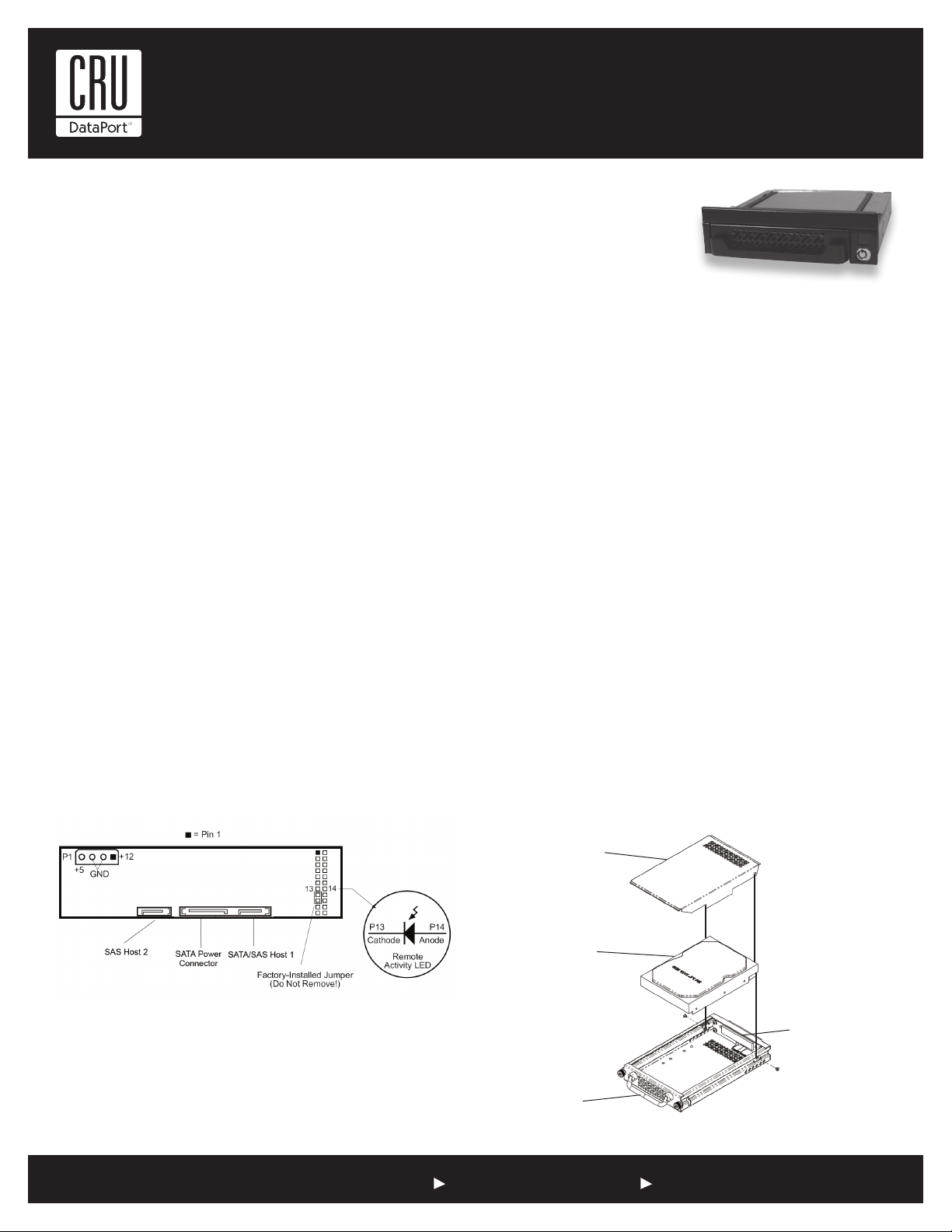
Receiving Frame Board
Factory-Installed Jumper (Pins 15 & 17) – Factory-installed
jumper. DO NOT REMOVE!
Remote Activity LED (RLED) – These pins provide a remote
LED device activity indicator (Pin 13=Cathode, Pin 14-Anode).
Frame Data Connectivity – For SATA operation the SATA data
cable must be connected to the SAS/SATA Host 1 Connector.
SATA hard drives do not support the SAS Host 2 Connector. SAS
hard drives can use either SAS Host 1 Connector or SAS Host 2
Connector. The DE75 supports the SAS dual host feature for fail
over protection.
Note: SAS hard drives require a SAS host. SAS hard drives
will not work with a SATA host.
Connect SATA power or ATX power to the power connectors on the
back of the DE75. The DE75 will support either ATX or SATA power.
Slide the frame into an available drive bay and secure the frame.
Drive Installation
1. Carefully insert the drive into the carrier. Slide the drive towards the Drive Carrier Board, so that the I/O connector on the
drive mates with the connector on the Drive Carrier Board. Hold
the drive in place, then turn the drive/carrier assembly over.
2. Fasten the drive into place with the four provided #6-32
Phillips Under Cut Flat Hd. Screws. Some drives may require
minor adjustment to position before securing into carrier with
screws.
3. Install the provided drive cover. Insert the front end of the cover
first and then slide the cover towards the rear of the carrier.
Secure drive cover with the two provided #4-40 Phillips Under
Cut Flat Hd. Screws.
Drive Cover
(provided)
Figure 1: Receiving Frame Board (rear view)
Frame Installation
For SATA operation connect a SATA data cable to the SATA/SAS
host 1 connector.
SATA/SAS Drive
(not included)
Drive Carrier
Board
Drive Carrier
Figure 2: Drive Installation Overview
1-800-260-9800 www.CRU-DataPort.com
Page 2
Rugged, Reliable, Mobile, Secure
TM
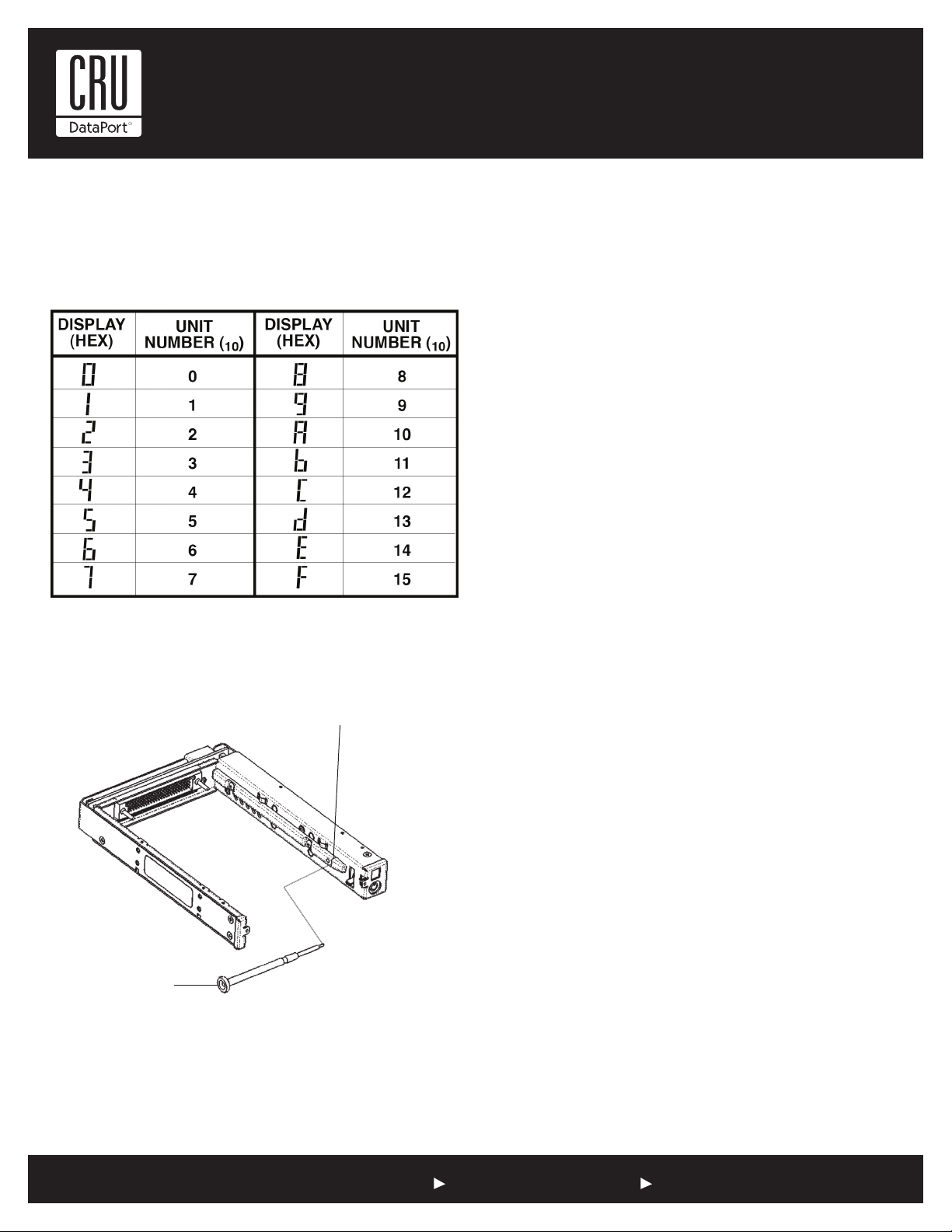
Unit ID Select Switch Settings
Note: The unit ID number display is for ID display purposes only.
The following table lists the unit ID select switch settings.
Table 1: Unit ID Hex Reference
Selecting the Unit ID Number: Use the alignment tool (provided) to select the ID number of the disk drive.
Unit ID Select Switch
Package Contents
1 - Key set
1 - Alignment tool
2 - 4-40 x 1/8” Flathead screws (carrier cover)
4 - 6-32 x 1/4” Flathead screws (drive mounting)
4 - M3 x 6mm Trusshead screws (frame mounting)
Limited Product Warranty
CRU-DataPort (CRU) warrants the Data Express DE75 to be free
of significant defects in material and workmanship for a period of
five years from the original date of purchase. CRU’s warranty is
nontransferable and is limited to the original purchaser.
Limitation of Liability
The warranties set forth in this agreement replace all other warranties. CRU expressly disclaims all other warranties, including
but not limited to, the implied warranties of merchantability and
fitness for a particular purpose and non-infringement of third-party
rights with respect to the documentation and hardware. No CRU
dealer, agent or employee is authorized to make any modification,
extension, or addition to this warranty. In no event will CRU or
its suppliers be liable for any costs of procurement of substitute
products or services, lost profits, loss of information or data, computer malfunction, or any other special, indirect, consequential,
or incidental damages arising in any way out of the sale of, use
of, or inability to use any CRU product or service, even if CRU has
been advised of the possibility of such damages. In no case shall
CRU’s liability exceed the actual money paid for the products at
issue. CRU reserves the right to make modifications and additions
to this product without notice or taking on additional liability.
Alignment Tool
Figure 3: Unit ID Select Switch Location
NOTE: The lock on the Data Express serves as a power
switch. It must be engaged (turned counterclockwise) for the
Data Express to power up and function properly.
Register your product at www.CRU-DataPort.com.
A7-075-0005 Rev. 1.0
1-800-260-9800 www.CRU-DataPort.com
 Loading...