

Page 1
Rugged, Reliable, Mobile, Secure
Data Express DE110 Ultra ATA133
Removable Ultra ATA133 Drive Enclosure
NOTES: For Ultra ATA133 (133MByte/sec) operation, an Ultra ATA133 controller
and hard drive (s), and appropriate 40-pin, 80-conductor cable are required.
Receiving Frame Motherboard
TM
Master/Slave Selection Jumper (ID0 & ID1) - Master Drive
designation (jumper is factory-installed on ID0). Change jumper
position to Pins 3 & 4 (ID1) for Slave Drive designation.
Forces Master/Slave Drive configuration on the receiving frame, if
jumper option on the drive itself is configured for Cable Selection
(recommended configuration). Refer to section “Master/Slave Drive
Section” for further information.
If using the Drive Select Method, this option is instead used to
configure the unit ID display only (refer to section “Master/Slave
Drive Section” for further information).
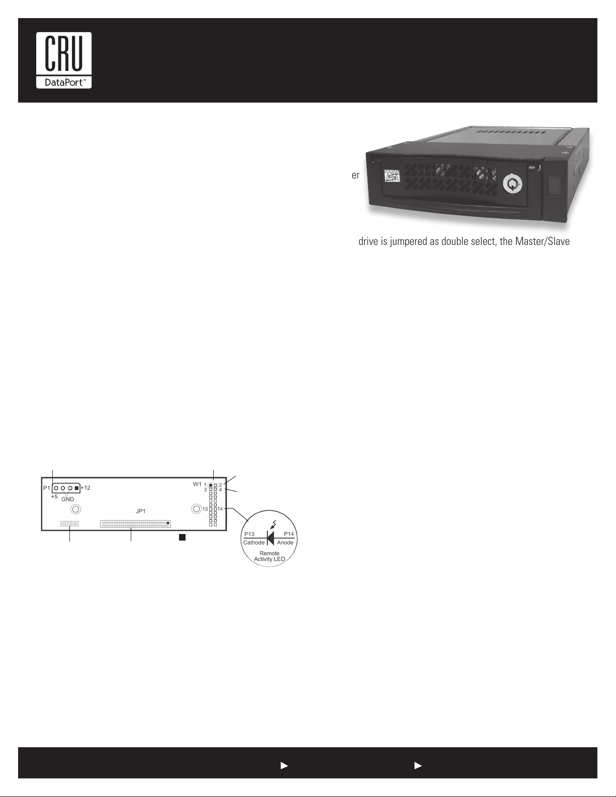
Remote Activity LED (RLED) - These pins provide power for a remote LED device activity indicator (Pin 13 = Cathode, Pin 14 = Anode).
Factory Reserved Pins - These pins are reserved for factory use
only - Do not install jumper under any circumstances!
DC Power
Connector (P1)
Option Pin
Connector (W1)
Master Drive
Select (ID0) (factory
installed jumper)
Slave Drive Select
(ID1)
When the drive is jumpered as double select, the Master/Slave
designation is handled by the Master/Slave Selection Jumper Option
(ID0 & ID1) located on the receiving frame motherboard. If necessary, reconfigure jumper (jumper is factory-configured for Master
Drive designation). Skip “Drive Select Method” and continue with the
Installation process.
2. Drive Select Method: In most cases, the drive will be factory
configured as a Master Drive using a jumper option on the drive
itself. Reconfigure the jumper if necessary (refer to the drive
manufacturer’s documentation for exact Master/Slave jumper
settings).
Reconfigure the jumper (jumper is factory installed on ID0 for Master
Drive designation) on the receiving frame motherboard to match the
hard drive.
NOTE: Since specifications (specifically, pin assignments)
between drive manufacturers may vary, please refer to your
drive manufacturer’s documentation for exact information
regarding Master/Slave and Cable Select configuration.
= Pin 1
Factory Reserved Pins
(no jumper installed)
Figure 1: Receiving Frame Motherboard (Rear View)
I/O Connector
(JP1)
Master/Slave Drive Selection
There are two ways to set the Master/Slave Drive designation for the
DE110 unit, as described below.
1. Cable Select Method (Recommended Method): In most cases,
the drive will be factory configured as a Master Drive using a
jumper option on the drive itself. CRU-DataPort, recommends
reconfiguring the drive for Cable Select. This can be done by configuring
the jumper on the drive itself (refer to the drive manufacturer’s
documentation for further information).
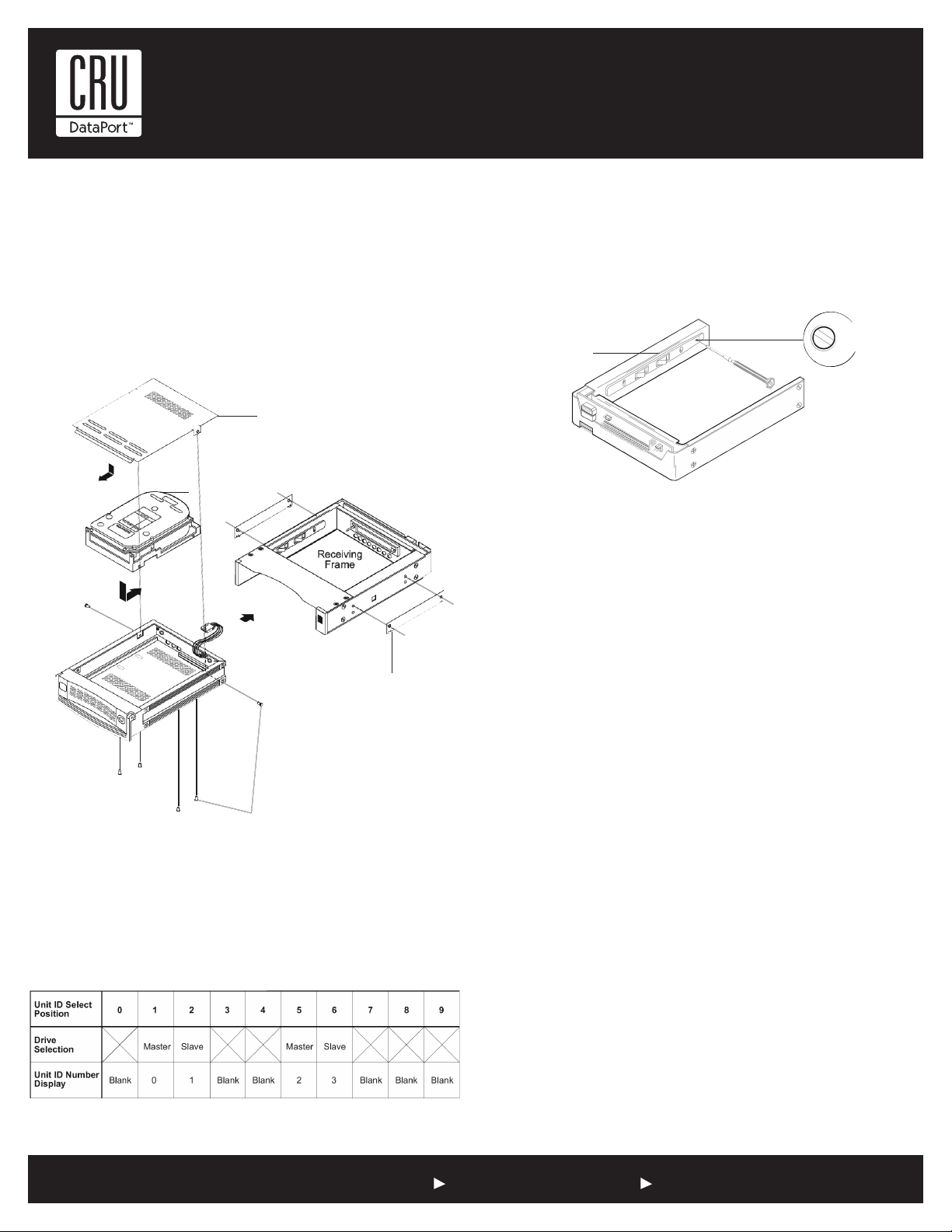
Installation
1. Attach the DC power cable (from the drive carrier board) to the drive.
2. Carefully insert drive into the carrier. Slide the drive towards the
Drive Carrier Board, so that the I/O connector on the drive mates
with the connector on the Drive Carrier Board. Make sure that the
DC power cable is not pinched. Turn the drive/carrier assembly over.
3. Fasten the drive into place with four (4) #6-32 Phillips Flat Hd.
screws. Some drives may require minor adjustment before securing
into carrier with screws.
4. Install the provided drive cover.
1-800-260-9800 www.CRU-DataPort.com
Page 2
Rugged, Reliable, Mobile, Secure
TM
Spacer Plates (Optional)
The DE110 is designed to fit most computer systems with standard
5.25” peripheral slots. The installation of the spacer plates (provided)
may or may not be necessary.
NOTE: Depending on the computer system, spacer plates may
be positioned on the receiving frame to utilize either top or bottom row of side-mounting holes.
Drive Cover
(provided)
Drive
(not included)
Figure 2: Drive Installation Assembly
Drive Carrier
Board
Drive
Carrier
#6-32 Phillips F. H.
Screw (6 total)
Spacer Plate*
(2 total)
*Note: Installation of Space
Plates is optional
NOTE: The unit ID number display is for ID display purposes
only (when using the “Drive Select Method”). The Master/Slave
setting must still be set on the drive itself (refer to section
“Master/Slave Drive Section” for further information).
Selecting the Unit ID Number: Use the alignment tool (provided)
to select the ID number of the disk drive.
Drive Carrier
Guide
Switch Location
Figure 4: Unit ID Select
Typical Data Express
Receiving Frame
NOTE: The lock on the Data Express receiving frame functions
as a lock and a DC power switch for the carrier unit. The lock
MUST be engaged (turned counterclockwise) in order to supply
power to the carrier and installed drive unit.
Limited Product Warranty
CRU-DataPort (CRU) warrants the Data Express DE110 to be free of significant defects in
material and workmanship for a period of five years from the original date of purchase. CRU’s
warranty is nontransferable and is limited to the original purchaser.
Limitation of Liability
The warranties set forth in this agreement replace all other warranties. CRU expressly disclaims
all other warranties, including but not limited to, the implied warranties of merchantability and
fitness for a particular purpose and non-infringement of third-party rights with respect to the
documentation and hardware. No CRU dealer, agent or employee is authorized to make any
modification, extension, or addition to this warranty. In no event will CRU or its suppliers be
liable for any costs of procurement of substitute products or services, lost profits, loss of information or data, computer malfunction, or any other special, indirect, consequential, or incidental damages arising in any way out of the sale of, use of, or inability to use any CRU product or
service, even if CRU has been advised of the possibility of such damages. In no case shall CRU’s
liability exceed the actual money paid for the products at issue. CRU reserves the right to make
modifications and additions to this product without notice or taking on additional liability.
Unit ID Select
Rotating Switch
Unit ID Select Switch Settings
The following table lists the unit ID select switch settings and the
valid AT/IDE unit numbers. Please note that all invalid switch settings
have X’s and result in a blank display in the receiving frame window.
Figure 3: Unit ID Select Switch Settings
Certification
EMI Standard: FCC Part 15 Class B, CE
EMC Standard: EN55022, EN55024
FCC Certification
This device has been tested and found to comply with the limits for a Class B
digital device, pursuant to Part 15 of the FCC rules. Operation is subject to the
following two conditions:
1. This device may not cause harmful interference.
2. This device must accept any interference received; including interference that
may cause undesired operation.
Register your product at www.CRU-DataPort.com
A7-110-0002 Rev. 1.2
1-800-260-9800 www.CRU-DataPort.com
 Loading...