

Page 1
Rugged, Reliable, Mobile, Secure
DataPort 10 USB-to-SATA Install Guide
The New DataPort 10 USB-to-SATA makes data backup and data security easy,
enabling hot-swap (removing the backup hard drive while the system is still on) of
any capacity Serial ATA (SATA) hard disk drive, from a 5.25” (half-height) expansion
bay, while the rugged removable carrier protects your HDD during transport and
storage.
Package Contents
1 - DataPort 10 USB-to-SATA frame assembly
1 - DataPort 10 carrier assembly
1 - Metal cover
1 - Internal USB cable
1 - Internal to external USB cable with bracket
4 - #6-32 x 1/4 fl at head screws for drive mounting
4 - M3 x 5 pan head screws for frame installation
2 - Keys for lock
Mounting the Frame in the Computer
1. Turn off the computer and disconnect its power cord from the electrical outlet. Before working on your computer, wait one minute for any
residual energy to dissipate. Ground yourself and then remove the
cover of the computer. Select the 5.25” half-height bay where you plan
to mount the DataPort frame assembly. Remove any fi ller plates that
may be present.
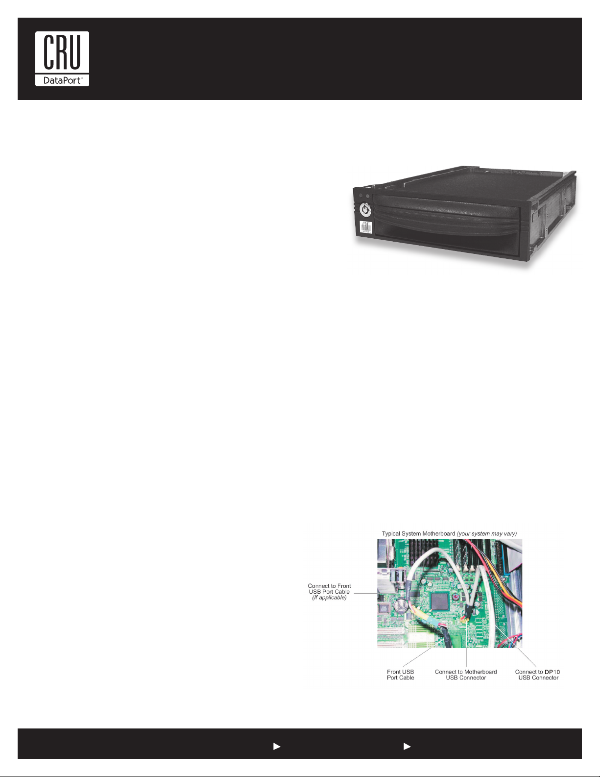
5. Locate a spare 9-Pin USB connector on the system motherboard and
connect the female connector on the split USB cable (provided) to it
(Figure 1).
Note: If your system motherboard has only one 9-Pin USB conetor
and it is connected to the front USB ports, disconnect the front
USB port cable from the system motherboard USB connector.
Connect the female connector on the split USB cable (provided) to
the newly vacated USB connector located on the system motherboard (Figure 1). If applicable, connect the male connector on the
split USB cable to the front USB port cable (Figure 1). Make sure
the red wires on both cables are correctly aligned.
NOTE: Connecting the DataPort 10 USB-to-SATA to the system
motherboard’s only USB connector will disable one of the front
USB ports (if applicable).
TM
2. To mount the frame assembly in the drive bay:
a. Check the drive bay to see if mounting rails are required (they
should be provided by your computer system manufacturer.) If
required, install one on each side of the frame. Slide the frame
into the computer and check that it is secure.
b. If mounting rails are not required, attach the frame directly to
the PC case using the screws provided. Either the side or bottom mount holes on the frame can be used.
3. For SATA operation, locate a SATA data cable and connect it to the
SATA connector on the frame. For USB operation see Step 4.
4. Locate the USB connector(s) on the system motherboard. Depending
on your system motherboard, it may have one or more 9-Pin USB connectors (with one typically connected to front USB ports on the PC), or
it may have only a 4-Pin USB connector. If your system motherboard
has 9-Pin USB connectors proceed to Step 5. If your system motherboard only has a Type B USB connector, proceed to Step 6.
6. If your system only has an available Type B USB connector, remove an
empty PCI slot bracket. Install the Internal USB PCI Bracket. Connect
the USB cable to an available USB port on the back of your computer
chassis and then connect it to your DataPort 10 USB-to-SATA frame.
Figure 1: Internal USB Cable
1-800-260-9800 www.CRU-DataPort.com
Page 2

Rugged, Reliable, Mobile, Secure
TM
8. Locate an available 4-Pin molex power cable from the computer power
supply and plug it into the power connector on the frame.
The frame installation is now completed.
Mounting a Hard Drive in the Carrier
1. The metal cover for DataPort 10 is secured by a screw. Remove the screw
and slide the top cover off the DataPort 10 carrier.
2. Slide the hard drive in from the front of the carrier and connect it
to the carrier circuit board. If the hard drive does not fit, remove the
screw holding the circuit board in the carrier. Place the hard drive in
the carrier, then connect the circuit board to the hard drive. Secure
the circuit board with the screw and then secure the hard drive with
the provided screws.
3. Attach the Temperature Control Cooling Sensor (TCCS) to the top
of the hard drive with an adhesive strip. After the drive has been
installed, replace the top cover and secure it with the provided screw.
4. Insert the carrier into the frame assembly. Ensure that the lock of the
DataPort is in the “open” (vertical) position. Position the carrier on the
guide rails, and then slide the carrier into the frame. Using thumb pres
-
sure, fully seat the carrier in the frame and lock the unit with the key lock.
Operation
Turn on the Power
The lock on the DataPort locks the carrier in place and also serves as the
power “ON/OFF” switch. Turn the lock 90 degrees clockwise to the “ON”
position before turning on the computer. When the computer is turned
on, the “Power On” LED (green light emitting diode above the key on the
frame assembly) is illuminated, and your system should operate normally.
Setting up the drive for Windows 2000/XP/Vista or Mac OS 9.x/X
No new drivers are required. The hard disk drive will be found and a
window will pop up stating “new hardware has been detected”.
For PCs:
• Right click on My Computer.
• Click on Manage.
• In the Storage sub-section, click on Disk Management to display a list of all the drives connected to your computer.
• Left click on Action, select All Tasks and then left click on Create Partition.
REMEMBER, partitioning the drive will require the drive to be formatted
which will result in loss of all data on the hard drive.
• This will bring up the Create Partition Wizard screen.
• Follow the instructions and the drive will be ready for use.
For Macs:
You will be asked to initialize the drives. After initializing the
drive, select the partition tab and select the desired partitions,
then click ok. The new disk(s) will be added to your desktop.
REMEMBER, formatting will result in loss of all data on the hard drive(s).
Fan Failure Alarm
The fan failure alarm function is a standard feature on the DataPort 10
USB-to-SATA. If the cooling fan should fail, an alarm will beep and the
green LED on the upper left corner of the DataPort will flash indicating
fan failure. Removal of the jumper on JP6 will silence the audible alarm
on the frame. Save the jumper to re-install after replacing the fan. Please
contact CRU to obtain a replacement fan.
Power Adapters
If your computer does not have an available Molex/ATX connector
you can purchase a SATA (host)-to-Molex/ATX (device) adapter on our
website.
Product Warranty
CRU-DataPort (CRU) warrants the DataPort 10 USB-to-SATA to be free
of significant defects in material and workmanship for a period of one
year from the original date of purchase. CRU’s warranty is nontransfer
-
able and is limited to the original purchaser.
Limitation of Liability
The warranties set forth in this agreement replace all other warranties. CRU
expressly disclaims all other warranties, including but not limited to, the implied
warranties of merchantability and fitness for a particular purpose and non-in
fringement of third-party rights with respect to the documentation and hardware.
No CRU dealer, agent or employee is authorized to make any modification, exten
sion, or addition to this warranty. In no event will CRU or its suppliers be liable
for any costs of procurement of substitute products or services, lost profits, loss
of information or data, computer malfunction, or any other special, indirect, con
sequential, or incidental damages arising in any way out of the sale of, use of,
or inability to use any CRU product or service, even if CRU has been advised of
the possibility of such damages. In no case shall CRU’s liability exceed the actual
money paid for the products at issue. CRU reserves the right to make modifica
tions and additions to this product without notice or taking on additional liability.
-
-
-
Register your product at www.CRU-DataPort.com.
-
A5-010-0003 Rev. 1.1
1-800-260-9800 www.CRU-DataPort.com
 Loading...