

Page 1
XLC Series Power Ampliers
XLC系列功率放大器
Operation Manual
操作手册
Obtaining Other Language Versions: To obtain information in another language about the use of this product, please
contact your local Crown Distributor. If you need assistance locating your local distributor, please contact Crown at +1 (574)
294-8000.
This manual does not include all of the details of design, production, or variations of the equipment. Nor does it cover every
possible situation which may arise during installation, operation or maintenance.
The information provided in this manual was deemed accurate as of the publication date. However, updates to this information
may have occurred. To obtain the latest version of this manual, please visit the Crown website at www.crownaudio.com.
Trademark Notice: Crown, Crown Audio and Amcron are registered trademarks of Harman International. Other trademarks
are the property of their respective owners.
Some models may be exported under the name Amcron®.
© 2013 Harman International, 1718 W. Mishawaka Rd., Elkhart, Indiana 46517-9439 U.S.A. Telephone:
+1 (574) 294-8000
FAULT
CLIP
SIGNAL
CH 1
CH 1
CH 2
FAULT
CLIP
SIGNAL
CH 2
获取其他语言版本:如果您需要其它语言版本的产品使用说明,请联系当地的Crown产品零售商。
如果您需要查询您当地的零售商以便获取帮助,请致电+1(574)294-8000 与Crown公司联系。
本手册不包含相关设备设计、生产或变更的所有详细信息。也不涵盖设备安装、操作或维护过程中
可能出现的每种情况。
本手册里提供的信息在出版时为准确无误。然而,我们仍可能在出版本手册后更新相应内容。如果
您需要获取本手册的最新版本,请登录Crown的官方网站www.crownaudio.com。
商标声明:Crown、Crown Audio 与 Amcron 是 Crown International 的注册商标。HiQnet 是
Harman International Industries, Inc. 的商标。其他商标均为其各自所有者的财产。
部分型号的产品可能是以Amcron®的商标出口。
© 2013 Harman International 版权所有。地址:1718 W. Mishawaka Rd., Elkhart, Indiana
46517-9439 U.S.A. 电话号码:+1(574)294-8000
XLC
XLC
2500
2800
XLC 2500
XLC 2800
请关注我们的微信
“harmanpro”
请关注我们的新浪微博
“哈曼专业音响中国”
5034994-C
03/14
Page 2

XLC Series Power Ampliers
Important Safety Instructions
重要的安全说明
1. Read these instructions.
2. Keep these instructions.
3. Heed all warnings.
4. Follow all instructions.
5. Do not use this apparatus near water.
6. Clean only with a dry cloth.
7. Install in accordance with the manufacturer’s instructions.
8. Do not install near any heat sources such as radiators, heat
reg isters, stoves, or other apparatus (including amplifiers) that
produce heat.
9. Do not defeat the safety purpose of the polarized or groundingtype plug. A polarized plug has two blades with one wider than
the other. A grounding-type plug has two blades and a third
grounding prong. The wide blade or the third prong is provided
for your safety. If the provided plug does not fit into your outlet,
consult an electrician for replacement of the obsolete outlet.
10. Protect the power cord from being walked on or pinched, par-
ticularly at plugs, convenience receptacles, and the point where
they exit from the apparatus.
11. Only use attachments/accessories specified by the manufac-
turer.
12. Use only with a cart, stand, tripod, bracket, or table specified
by the manufacturer, or sold with the apparatus. When a cart is
used, use caution when moving the cart/apparatus combination
to avoid injury from tip-over.
13. Unplug this apparatus during lightning storms or when unused
for long periods of time.
14. Refer all servicing to qualified service personnel. Servicing is
required when the apparatus has been damaged in any way,
such as power-supply cord or plug is damaged, liquid has been
spilled or objects have fallen into the apparatus, the apparatus
has been exposed to rain or moisture, does not operate normally, or has been dropped.
15. Use the mains plug to disconnect the apparatus from the mains.
16. WARNING: TO REDUCE THE RISK OF FIRE OR ELECTRIC
SHOCK, DO NOT EXPOSE THIS APPARATUS TO RAIN OR
MOISTURE.
17. DO NOT EXPOSE THIS EQUIPMENT TO DRIPPING OR
SPLASHING AND ENSURE THAT NO OBJECTS FILLED
WITH LIQUIDS, SUCH AS VASES, ARE PLACED ON THE
EQUIPMENT.
18. THE MAINS PLUG OF THE POWER SUPPLY CORD SHALL
REMAIN READILY OPERABLE.
WATCH FOR THESE SYMBOLS:
注意这些符号:
The lightning bolt triangle is used to alert the user to the risk of electric
shock.
闪电三角形符号用来提示用户注意电击的危险。
The exclamation point triangle is used to alert the user to important
operating or maintenance instructions.
感叹号三角形符号用来提示用户重要的操作或者维护说
明。
XLC系列功率放大器
1. 请阅读这些说明。
2. 请妥善保管这些说明。
3. 请留意所有警告。
4. 请遵守所有这些说明。
5. 请勿在靠近水的地方使用本产品。
6. 清理时只能使用干布。
7. 请严格按照制造商提供的操作说明进行安装。
8. 不要将本产品直接安装在任何热源,比如散热
器、电热器、火炉或者其他产生热量的设备(包
括功放)上。
9. 不要破坏具有安全功效的极性插头或者接地式插
头。极性插头有两个插脚,一个宽,一个窄。接
地式插头有两个插脚和一个接地插脚,其中宽插
片或者接地插脚是用来保障您的安全的。如果所
提供的插头不适合您的插座,请咨询联系电工更
换适合的插座。
10. 保护电源线。避免电源线被踩踏或者被捻搓。特
别注意保护在插头、便捷插座和电源线接出设备
处的电源线。
11. 仅使用制造商指定的附件和配件。
12. 仅使用制造商指定的或者随本产品一同出售的载
车、支架、三角架、托架或者工作台。在使用推
车运输设备时,特别注意推车及设备,避免其翻
倒造成伤害。
13. 在有雷电时或者长时间不使用本产品时,请拔掉
本产品的插头。
14. 所有维修服务必须由有资格的维修人员提供。当
设备受到任何形式的损坏时,比如电源线或者插
头被损坏,液体或者异物掉入设备,遭受雨淋或
受潮,不能正常工作,以及被摔碰等情况,都需
要维修。
15. 应采用断开主电源线与市电插座连接的方法来断
开产品与电源的连接。
16. 警告:为降低失火或者电击的风险,不要让设备
遭受雨淋或者受潮。
17. 不要将产品放置在容易遭受滴漏或者喷洒的地
方。例如,不要将装有液体的物品,比如花瓶等
放到设备上。
18. 请确保电源插头可随时插拔使用。
此设备仅按海拔2000m进行安全设计与评估,因此,仅
适用于在海拔2000m以下安全使用,在海拔2000m以上
使用时,可能有安全隐患。
此设备仅按非热带气候条件进行安全设计与评估,因
此,仅适用于在非热带气候条件下安全使用,在热带
气候条件下使用时,可能有安全隐患。 要完全断开此
设备与交流电主线的连接,请把电源线插头从交流电
插座中拔出。需要连接电源时,可再次将电源线插头
插入交流电插座。
WARNING: THE APPARATUS WITH CLASS I CONSTRUCTION SHALL BE CONNECTED TO
A MAINS SOCKET OUTLET WITH A PROTECTIVE EARTHING CONNECTION.
警告:I类结构的设备应当连接到带保护接地连接的电网电源输出插座上。
TO PREVENT ELECTRIC SHOCK DO NOT REMOVE TOP OR BOTTOM COVERS. NO
USER SERVICEABLE PARTS INSIDE. REFER SERVICING TO QUALIFIED SERVICE
PERSONNEL.
为了避免电击,请不要拆卸设备。设备内部无用户可以自行维护的部
件。请向有资格的服务人员咨询。
TO COMPLETELY DISCONNECT THIS EQUIPMENT FROM THE AC MAINS, DISCONNECT THE POWER SUPPLY CORD PLUG FROM THE AC RECEPTACLE. THE MAINS
PLUG OF THE POWER SUPPLY CORD SHALL REMAIN READILY OPERABLE.
要完全断开此设备与交流电主线的连接,请把电源线插头从交流电插
座中拔出。需要连接电源时,可再次将电源线插头插入交流电插座。
MAGNETIC FIELD
CAUTION! Do not locate sensitive high-gain equipment such as preamplifiers directly above or below the
unit. Because this amplifier has a high power density, it has a strong magnetic field which can induce hum
into unshielded devices that are located nearby. The field is strongest just above and below the unit.
If an equipment rack is used, we recommend locating the amplifier(s) in the bottom of the rack and the
preamplifi er or other sensitive equipment at the top.
磁场
警告!不要把敏感的高增益设备,如前置放大器或大型录音机直接放在其上或者旗
下,因为此功放具有大功率密度,形成强磁场,这种磁场会使靠近的未屏蔽的设备
产生嘈杂声。扩音器的上部和下部磁场最强。
如果使用设备架,我们建议把功放放在架的底部,把前置放大器或者其他敏感设备
放在架顶。
FCC COMPLIANCE NOTICE
This device complies with part 15 of the FCC rules. Operation is subject to the following two
conditions: (1) This device may not cause harmful interference, and (2) this device must accept
any interference received, including interference that may cause undesired operation.
CAUTION: Changes or modifications not expressly approved by the party responsible for compliance could void the user’s authority to operate the equipment.
NOTE: This equipment has been tested and found to comply with the limits for a Class B digital
device, pursuant to part 15 of the FCC Rules. These limits are designed to provide reasonable
protection against harmful interference in a residential installation. This equipment generates,
uses, and can radiate radio frequency energy and, if not installed and used in accordance with
the instruction manual, may cause harmful interference to radio communications. However, there
is no guarantee that interference will not occur in a particular installation. If this equipment does
cause harmful interference to radio or television reception, which can be determined by turning
the equipment off and on, the user is encouraged to try to correct the interference by one or more
of the following measures:
• Reorient or relocate the receiving antenna.
• Increase the separation between the equipment and receiver.
• Connect the equipment into an outlet on a circuit different from that to which the receiver is
connected.
• Consult the dealer or an experienced radio/TV technician for help.
page 2
Operation Manual
操作手册
Page 3

XLC Series Power Ampliers
XLC系列功率放大器
Crown International, Inc.
ISSUED BY: Harman International
1718 W. Mishawaka Road
Elkhart, Indiana 46517 U.S.A.
European Representative’s Name and Address:
David Budge
10 Harvest Close
Yateley GU46 6YS
United Kingdom
Equipment Type: Power Amplifiers
Family Name: XLC series
Model Names: XLC2500, XLC2800
EMC Standards:
EN 55103-1: 2009 EMC Compatibility – Product Family Standard for Audio, Video, Audio-Visual and Entertainment Lighting Control Apparatus for Professional Use, Part 1: Emissions
EN 55103-1: 2009 Magnetic Field Emissions – Annex A @ 10cm and 20cm
EN 61000-3-2: 2006 Limits for Harmonic Current Emissions (equipment input current less than or equal to 16A
EN 61000-3-3: 2008 Limitation of Voltage Fluctuations and Flicker in Low-Voltage Supply systems Rated Current less than or equal to 16A
EN 55022: 2010 Limits and Methods of Measurement of Radio Disturbance Characteristics of ITE: Radiated & Conducted, Class B Limits
EN 55103-2: 2009 EMC Compatibility – Product Family Standard for Audio, Video, Audio-Visual and Entertainment Lighting Control Apparatus for Professional Use, Part 2: Immunity
EN 61000-4-2: 2008 Ed 2.0 Electrostatic Discharge Immunity (Environment E2-Criteria B, 4k V Contact, 8k V Air Discharge)
EN 61000-4-3: 2010 Ed 3.2 Radiated, Radio-Frequency, EMC Immunity (Environment E2, Criteria A)
EN 61000-4-4: 2007 Electrical Fast Transient/Burst Immunity (Criteria B)
EN 61000-4-5: 2006 Surge Immunity (Criteria B)
EN 61000-4-6: 2006 Immunity to Conducted Disturbances Induced by Radio-Frequency Fields (Criteria A)
EN 61000-4-11: 2004 Voltage Dips, Short Interruptions and Voltage Variation
DECLARATION of CONFORMITY
Safety Standards:
IEC 60065:2001 Ed 7 +A1:2005 +A2:2010 Safety Requirements – Audio, Video, and Similar Electronic Apparatus
CAN/CSA 60065-03 +A1 +A2 Safety Requirements – Audio, Video, and Similar Electronic Apparatus
UL Std No 60065-03 (2012) Safety Requirements – Audio, Video, and Similar Electronic Apparatus
I certify that the product identified above conforms to the requirements of the EMC Council Directive 2004/108/EC and the Low Voltage Directive 2006/95/EC.
Signed
Jeff Denman
Senior Director, Operations
Operation Manual
操作手册
Date of issue: September 06, 2013
page 3
Page 4

XLC Series Power Ampliers
XLC系列功率放大器
Table of Contents
1. Welcome .............................................................................................5
1.1 Features ......................................................................................................................................................... 5
1.2 How to use this manual .................................................................................................................................. 5
2. Setup .................................................................................................6
2.1 Unpacking ...................................................................................................................................................... 6
2.2 Installing the amplifier .................................................................................................................................... 7
2.3 Ensuring Proper Cooling ................................................................................................................................ 7
2.4 Wiring to the CXM2000 Monitor and Crossover System ................................................................................ 8
2.5 Alternative: Choosing Phoenix Connectors as Input Connectors .................................................................... 9
2.6 Choosing Output Wiring and Connectors ...................................................................................................... 9
2.7 Wiring Your System ..................................................................................................................................... 10
2.7.1 Stereo Mode ..................................................................................................................................... 10
2.7.2 Parallel Mode ................................................................................................................................... 10
2.7.3 Bridge Mode ..................................................................................................................................... 11
2.8 Connecting to AC Mains .............................................................................................................................. 11
2.9 Protecting Your Speakers ............................................................................................................................. 11
3. Operation .......................................................................................... 12
3.1 Precautions .................................................................................................................................................. 12
3.2 Startup Procedure ........................................................................................................................................ 12
3.3 Front Panel ................................................................................................................................................... 13
3.4 Rear Panel .................................................................................................................................................... 14
4. Advanced Features and Options ................................................................ 15
4.1 System Protection ........................................................................................................................................ 15
4.1.1 Output Current Limiting.................................................................................................................... 15
4.1.2 Fault ................................................................................................................................................. 15
4.1.3 AC Under Voltage Protection ............................................................................................................ 15
4.1.4 Thermal ............................................................................................................................................ 15
4.1.5 Circuit Breaker (Reset Button) .......................................................................................................... 15
4.1.6 Output Connector Security Cover ..................................................................................................... 15
5. Troubleshooting ................................................................................... 16
6. Specifications ..................................................................................... 18
7. Service ............................................................................................. 22
8. Warranty ........................................................................................... 24
目录
1. 欢迎 ................................................................. 5
1.1 特点 ................................................................... 5
1.2 如何使用本手册 ......................................................... 5
2. 安装 ................................................................. 6
2.1 拆箱 ................................................................... 6
2.2 安装功放 ............................................................... 7
2.3 保证正常散热 ........................................................... 7
2.4 连接至CXM2000扬声器优化/监听系统 ....................................... 8
2.5 可选:选择凤凰头作为输入接口 ........................................... 9
2.6 选择输出连接线和接口 ................................................... 9
2.7 连接系统 .............................................................. 10
2.7.1 立体声模式 ....................................................... 10
2.7.2 并行模式 ......................................................... 10
2.7.3 桥接模式 ......................................................... 11
2.8 连接到电源 ............................................................ 11
2.9 保护您的扬声器 ........................................................ 11
3. 操作 ................................................................ 12
3.1 预防措施 .............................................................. 12
3.2 启动步骤 .............................................................. 12
3.3 前面板 ................................................................ 13
3.4 后面板 ................................................................ 14
4. 高级功能和选项 ...................................................... 15
4.1 保护系统 .............................................................. 15
4.1.1 输出电流限制 ..................................................... 15
4.1.2 故障 ............................................................. 15
4.1.3 交流电压过低保护 ................................................. 15
4.1.4 过热 ............................................................. 15
4.1.5 断路器(复位键) ................................................. 15
4.1.6 输出接口防触摸保护壳 ............................................. 15
5. 故障诊断 ............................................................ 16
6. 产品规格 ............................................................ 18
7. 服务 ................................................................ 23
8. 保修 ................................................................ 26
page 4
Operation Manual
操作手册
Page 5

XLC Series Power Ampliers
XLC系列功率放大器
XLC 2500
1kHz Power
1kHz 功率
2Ω Dual (per channel)
2Ω双通道(每声道)
4Ω Dual (per channel)
4Ω双通道(每声道)
8Ω Dual (per channel)
8Ω双通道(每声道)
8Ω Bridge
1000W
8Ω桥接
With 0.5% THD. 基于0.5%THD所得值。
775W
500W
300W
XLC 2800
2Ω Dual (per channel)
2Ω双通道(每声道)
4Ω Dual (per channel)
4Ω双通道(每声道)
8Ω Dual (per channel)
8Ω双通道(每声道)
8Ω Bridge
8Ω桥接
With 0.5% THD. 基于0.5%THD所得值。
*With 1% THD. *基于1%THD所得值。
1kHz Power
1kHz 功率
1200W
775W / 800W*
440W
1550W / 1600W*
1. Welcome
Thank you for purchasing the Crown® XLC series amplifier. The XLC2500 and XLC2800 are specially designed for cinema
applications. By connecting it to the Crown CXM2000 monitor and crossover system, you can monitor either the processor
input signals or the amplifier output signals. You can also see the fault alarms directly on the CXM2000 front panel or TMS
(Theater Management System) interface. Together with JBL BC series cinema speakers and Crown CXM2000, Crown XLC
series amplifiers offer a perfect cinema audio solution.
1.1 Features
• Two models of 500W (XLC2500) and 800W (XLC2800) per channel at 4 ohms.
• Compatible with JBL cinema speaker 3722(N), 4722(N), 3730, 3252(N), 4641, 4642A, 8320, 4181, 8281, 8340A,
8350, SCS8, SCS12 to deliver the high quality sound.
• Power for 2 ohm, 4 ohm and 8 ohm outputs, supporting stereo, parallel and bridge outputs.
• Volume control on rear panel.
• High performance, light weight class-D amplifier - weights less than 5kg (net weight).
• HD-15 and phoenix connectors make the system wiring easy.
• Indicators provide accurate diagnostics: Power, Signal, Clip and Fault.
• Compatible with Crown CXM2000 and DSi-8M for total audio system solution. Support the Crown CXM2000 for
monitor, fault detection and crossover functions. Support the Crown DSi-8M for monitor function.
1.2 How to use this manual
This manual provides you with the necessary information to safely setup and correctly operate your amplifier. However, it
does not cover every aspect of installation, setup or operation that might occur under every condition. For additional
information, please consult Crown’s Amplifier Application Guide (available online at www.crownaudio.com), Crown
Technical Support, your system installer, or the retailer where this amplifier was purchased.
We strongly recommend you read all instructions, warnings and cautions contained in this manual. Also, for your
protection, please send in your warranty registration card today. And save your bill of sale — it’s your official proof of
purchase.
FAULT
CLIP
SIGNAL
CH 1
CH 1
CH 2
FAULT
CLIP
SIGNAL
CH 2
XLC
XLC
2500
2800
1. 欢迎
欢迎您购买本产品,Crown XLC系列专业功放专为影院播放量身定做,有着稳定可靠的性能,
并为您提供完美的扬声器播放音质。Crown XLC系列功放与CXM2000扬声器优化和监听系统搭配
使用时,您可以通过CXM2000监听各通道的音频信号,也可以在CXM2000前面板或影院管理系统
(TMS)界面看到各通道的故障警告。Crown XLC系列功放与JBL影院扬声器和Crown CXM2000搭配
使用,为基础影院提供了一套完美的整体音频解决方案,能最大地满足他们的应用需求。
1.1 特点
• 两种型号可供选择,输出功率可达4欧姆每通道500W(XLC2500)和800W (XLC2800)。
• 完美搭配JBL影院扬声器3722(N)、4722(N)、3730、3252(N)、4641、4642A、8320、4181、
8281、8340A、8350、SCS8、SCS12实现震撼的影院音响效果。
• 2/4/8欧姆输出功率,可支持环绕扬声器或一般影院扬声器的立体声、并行和桥接模式。
• 音量控制位于后面板,可防止误操作。
• D类功放,性能高,重量轻,净重低于5公斤。
• 15针接口和凤凰头,可简化XLC功放与系统之间的输入/输出连接,使布线更简洁。
• 指示灯排列有序,显示电源以及每通道的信号、削波和故障的状况,从而正确判断功放的
现况。
• 与Crown CXM2000或DSi-8M搭配使用,提供整体的音频系统解决方案。并支持Crown
CXM2000实现监听、故障检测和分频功能。支持Crown DSi-8M实现监听功能。
1.2 如何使用本手册
本手册为您提供安全而正确地安装和使用功放的必要信息。但是,它不能涵盖安装、设置或者使
用该设备时可能出现的所有情况。如果您需要了解更多信息,请阅读Crown功放应用指南(您可
以访问www.crownaudio.com在线查看),您也可以向Crown的技术支持部门、您的系统安装人员
或销售地的经销商咨询。
我们强烈建议您仔细阅读本手册中的所有说明、警告和注意事项。另外,为保障您的利益,请立
即递送您的保修卡。并且保留您的购物单据,即您购买本设备的正式凭证。
Operation Manual
操作手册
page 5
Page 6
XLC Series Power Ampliers
XLC系列功率放大器
2. Setup
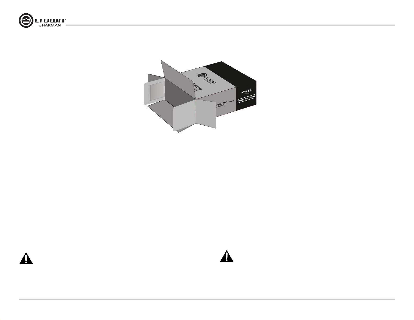
Figure 2.1 Package
图2.1 包装
2.1 Unpacking
Please unpack and inspect your XLC amplifier for any damage that may have occurred during transit. If damage is found,
notify the transportation company immediately. Only you can initiate a claim for shipping damage, though Crown will be
happy to help as needed. If the product arrived showing signs of damage, save the shipping carton for the shipper’s
inspection.
We also recommend that you save all packing materials so you will have them if you ever need to transport the unit. Never
ship the unit without the factory carton and packing materials.
Package contains:
• One XLC amplifier;
• One Power Cord (compatible to retailer’s location);
• One operation manual (this manual);
• One product registration form (at the end of this manual);
• One warranty card (at the end of this manual).
2. 安装
2.1 拆箱
请将包装箱打开并检查运输过程中设备是否受到损坏。如果发现损坏,请立即通知运输公司。
尽管 Crown 非常乐意在需要时提供帮助,但只有您可以对运输损坏提出索赔。如果产品到达时
显示损坏迹象,请保留包装箱,供运送方核查时,作为认定设备受损的证据。
另外,我们建议您保存所有的包装材料,留待将来运输设备时使用。请不要在没有使用原厂包装
箱和包装材料的情况下装运设备。
单套包装包括:
• 一台XLC功率放大器;
• 一根电源线(规格与经销商所在地匹配);
• 一本操作说明书(本说明书);
• 一份产品注册表(本说明书最后部分);
• 一张保修卡(本说明书最后部分)。
For installation, you will need (not supplied):
• Input wiring cables
• Output wiring cables
• Rack for mounting amplifier (or a stable surface for stacking)
NOTE: Before you start to set up your amplifier, make sure you read and observe the Important
Safety Instructions found at the beginning of this manual.
page 6
Operation Manual
安装时,您还需要(未提供):
• 输入信号电缆;
• 输出信号电缆;
• 用于架设功放的设备支架或稳固台面。
注意:在您安装使用本功放前,请确保已经阅读并遵守本手册前面所列的重要安全信
息。
操作手册
Page 7
XLC Series Power Ampliers
3.46 In.
8.8 cm
18.99 In.
48.25 cm
8.12 In.
20.65 cm
10.38 In.
26.36 cm
XLC2500
XLC2800
XLC
2500
FAULT
CLIP
SIGNAL
CH 2
CH 1
XLC系列功率放大器
2. Setup (continued)
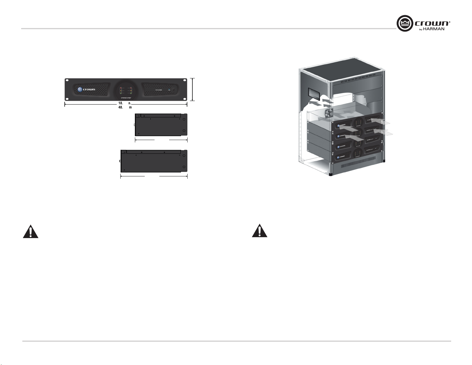
2.2 Installing the amplifier
Figure 2.2 Dimensions
图2.2 尺寸
2. 安装(接上一页)
Figure 2.3 Airflow
图2.3 气流流通
2.2 安装功放
NOTE: Before you begin, make sure your amplifier is disconnected from the power source, with
the power switch in the “off” position and all level controls turned completely down (counterclockwise).
Use a standard 19-inch (48.3 cm) equipment rack. See Figure 2.2 for amplifier dimensions. You may also stack amplifiers
without using a cabinet.
NOTE: Amplifiers should be supported at both the front and rear of the rack.
2.3 Ensuring Proper Cooling
When using an equipment rack, mount units directly on top of each other. Close any open spaces in rack with blank panels.
Do not block front or rear air vents. The back of the rack should be open.
Figure 2.3 illustrates standard amplifier airflow.
Operation Manual
注意:开始安装前,确保您已断开功放与电源的连接,将功放电源开关设置到关闭位
置,并将所有音量调节到最低(逆时针旋转)。
使用一个标准的19寸( 48.3厘米)设备机架。具体功放尺寸请参见图2.2。您还可以直接将功放
安放到平台上,而不用将功放安装到机柜。
注:机架前后均应该支撑功率放大器。
2.3 保证正常散热
在使用设备机架时,直接将设备安装在机架上。使用空白面板将所有开放的空间封闭。不要阻挡
前面和后面的通风口。机架的后面应该保持开放。
图2.3 显示标准的功放气流流通情况。
操作手册
page 7
Page 8
XLC Series Power Ampliers
L-Bi-amp
L&R-Passive
R-Bi-amp
Null-Passive
Sw1C Sw2 Ls/Rs Bsl/Bsr
INPUTS FROM PROCESSOR OUTPUTSRS-232
Firmware update
OUTPUTS TO POWER AMPLIFIER INPUTS
Speaker 1-4
System 5-8
1 2 3 4 5 6 7 8
ON
230
H
O
T
A
I
R
E
X
H
A
U
S
T
ON
12
H
O
T
A
I
R
E
X
H
A
U
S
T
ON
12
H
O
T
A
I
R
E
X
H
A
U
S
T
ON
12
H
O
T
A
I
R
E
X
H
A
U
S
T
ON
12
H
O
T
A
I
R
E
X
H
A
U
S
T
ON
12
H
O
T
A
I
R
E
X
H
A
U
S
T
ON
12
H
O
T
A
I
R
E
X
H
A
U
S
T
ON
12
L-Bi-amp
L&R-Passive
R-Bi-amp
Null-Passive
Sw1C Sw2 Ls/Rs Bsl/Bsr
INPUTS FROM PROCESSOR OUTPUTSRS-232
Firmware update
OUTPUTS TO POWER AMPLIFIER INPUTS
Speaker 1-4
System 5-8
1 2 3 4 5 6 7 8
ON
230
H
O
T
A
I
R
E
X
H
A
U
S
T
ON
12
H
O
T
A
I
R
E
X
H
A
U
S
T
ON
12
H
O
T
A
I
R
E
X
H
A
U
S
T
ON
12
H
O
T
A
I
R
E
X
H
A
U
S
T
ON
12
H
O
T
A
I
R
E
X
H
A
U
S
T
ON
12
H
O
T
A
I
R
E
X
H
A
U
S
T
ON
12
XLC系列功率放大器
2. Setup (continued)
CXM2000
XLC Series Amplifiers
L Channel
R Channel
C Channel
SW1 Channel
SW2 Channel
Ls&Rs Channel
Bsl&Bsr Channel
CXM2000
XLC Series Amplifiers
2. 安装(接上一页)
L&R Channel
C Channel
SW1 Channel
SW2 Channel
Ls&Rs Channel
Bsl&Bsr Channel
5 1
10
6
11
15
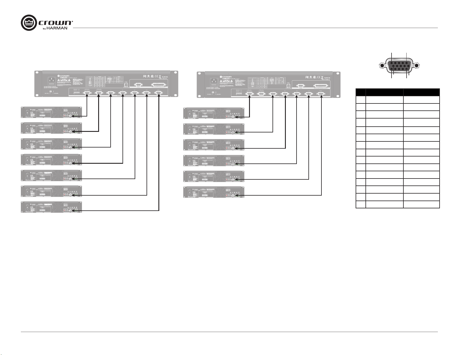
Pin CXM2000 Crown XLC series
1 CH1 Output - CH1 Input -
2 Null Null
3 V-MON CH1 Input V-MON CH1
4 CH1 Amp status CH1 Amp status
5 CH1 Load Current status CH1 Load Current status
6 Sig GND Sig GND
7 CH1 Output + CH1 Input +
8 CH2 Output + CH2 Input +
9 Null Null
10 Chassis GND Chassis GND
11 CH2 Output - CH2 Input -
12 Null Null
13 V-MON CH2 V-MON CH2
14 CH2 Amp status CH2 Amp status
15 CH2 Load Current status CH2 Load Current status
Figure 2.4 Wiring XLC Amplifiers to the CXM2000 in Bi-amplified Cinema Speakers System
图2.4 双功放通道驱动式扬声器系统中XLC功放与CXM2000的连接
2.4 Wiring to the CXM2000 Monitor and Crossover System
It is recommended to use the XLC Series amplifiers with the Crown CXM2000 Monitor and Crossover System. Figure 2.4
and figure 2.5 are the samples of wiring XLC amplifiers to the CXM2000 in bi-amplified cinema speakers system and
passive cinema speakers system through cables. This allows the CXM2000 to send the audio signals to and receive signals
from the XLC amplifiers for crossover, fault detection and monitor functions. More details about the wiring, please read the
Operation Manual of the CXM2000 Monitor and Crossover System.
Please see figure 2.6 for the HD-15 pin definition.
page 8
Operation Manual
Figure 2.5 Wiring XLC Amplifiers to the CXM2000 in Passive Cinema Speakers System
图2.5 被动式扬声器系统中XLC功放与CXM2000的连接
Figure 2.6 HD15 Pin Definition
图2.6 15针引脚定义
2.4 连接至CXM2000扬声器优化/监听系统
建议将XLC系列功放搭配Crown CXM2000扬声器优化/监听系统使用。图2.4和图2.5的示例,分
别为在双功放通道驱动式扬声器系统和被动式扬声器系统中,通过线缆连接功放的15针接口至
CXM2000。连接成功后,CXM2000可以输出优化后的音频信号,并接收来自XLC功放的监听信号和
故障检测信号,实现分频、监听和故障检测功能。更多详细的连接信息,请看CXM2000扬声器优
化/监听系统的操作手册。
关于15针接口的引脚定义,请看图2.6。
操作手册
Page 9
XLC Series Power Ampliers
XLC系列功率放大器
2. Setup (continued)
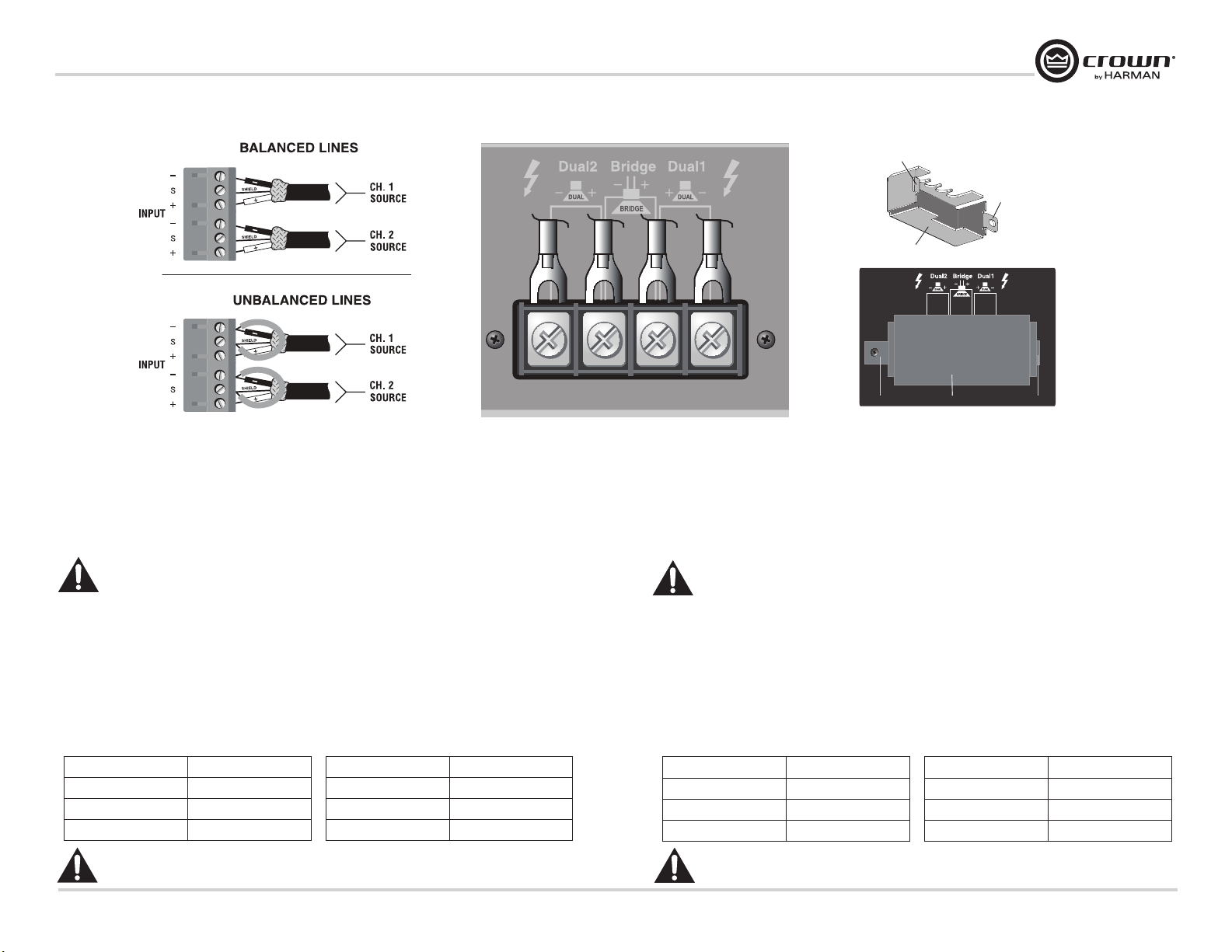
Figure 2.7 Input Wire and Connectors
图2.7 输入连接线和接口
2.5 Alternative: Choosing Phoenix Connectors as Input Connectors
Besides connecting the XLC amplifiers to the CXM2000 through HD-15 connector, you can also connect to other input
devices through the phoenix connectors on its rear panel. Crown recommends using pre-built or professionally wired
balanced line (two-conductor plus shield), 22-24 gauge cables and connectors (see Figure 2.7). Unbalanced lines may be
used, but may result in hum or RF noise over long cable runs.
NOTE: Custom wiring should only be performed by qualified personnel.
Figure 2.8 Output Wire and Connectors
图2.8 输出连接线和接口
2. 安装(接上一页)
Tab A
Tab B
Non-touch cover
Non-touch cover
Figure 2.9 Non-Touch Cover and Its Position
图2.9 防触摸保护壳及其安装位置
2.5 可选:选择凤凰头作为输入接口
除用HD-15接口连接XLC功放至CXM2000外,还可以选择后面板的凤凰头接口连接其他输入设
备。Crown建议您采用已有的或专业的平衡线(双导线带屏蔽),22-24线规的电缆和接口连接
凤凰插头(见图2.7)。您也可以使用非平衡线,但是,如果使用的电缆较长,会产生噪音或射
频干扰。
注意:必须由专业人员进行接线操作。
Tab ATab B
2.6 Choosing Output Wiring and Connectors
Crown recommends using pre-built or professionally wired, high-quality, two-conductor, heavy gauge speaker wire and
spade lug connectors or bare wire for your output connectors (Figure 2.8). To prevent the possibility of short-circuits, wrap
or otherwise insulate exposed loudspeaker cable connectors.
Non-Touch cover provides protection of electric shock from the output terminals. Remove it to connect the cables to the
output terminals and reinstall it when finish. To reinstall it, insert tab A into the slot right beside the output terminals (see
figure 2.9). Put the screw through tab B and screw it into the hole left beside the output terminals (see figure 2.9).
Below are the suggested guidelines to select the appropriate size of wire based on the distance from amplifier to speaker.
Distance Wire Size
up to 25 ft. 16 AWG
26-40 ft. 14 AWG
41-60 ft. 12 AWG
CAUTION: Never use shielded cable for output wiring.
NOTE: Custom wiring should only be performed by qualified personnel. Class 2 output wiring is required.
Distance Wire Size
61-100 ft. 10 AWG
101-150 ft. 8 AWG
151-250 ft. 6 AWG
Operation Manual
2.6 选择输出连接线和接口
在连接输出至扬声器时,Crown建议您采用已有或专业的,高质量的,双绞线的,大规格扬声器
线材及铲型接线片端口,或裸线(见图2.8)。为了防止短路,您需要包住或使用其他方法绝缘
外露的扬声器电缆接头。
防触摸保护壳用于对输出接口提供防电击保护。接线前需卸下保护壳,再连接线缆到输出接口;
在接线完成后,需装回保护壳。安装防触摸保护壳时,将页片A插入输出接口右侧的插槽内(见
图2.9),将螺丝穿过页片B,拧紧螺丝将其固定在输出接口右侧的小孔内(见图2.9)。
建议使用下表的指南,根据扩音器与喇叭的距离选择合适的音箱。
距离 尺寸
25英尺以下 16 AWG
26-40英尺 14 AWG
41-60英尺 12 AWG
警告:不要使用屏蔽电缆作为输出连接线!
注:定制接线只能由合格的人员执行。要求使用第 2 类输出接线。
操作手册
距离 尺寸
61-100英尺 10 AWG
101-150英尺 8 AWG
151-250英尺 6 AWG
page 9
Page 10

XLC Series Power Ampliers
Ch. 1 Source
XLC系列功率放大器
2. Setup (continued)
Ch. 2 amplifier output to HF
and MF driver
2.7 Wiring Your System
-
+
+
-
Ch. 1 amplifier output to LF driver
T
S
U
A
H
X
E
R
I
A
T
O
H
Figure 2.10 Stereo Mode
图2.10 立体声模式
JBL 3252
Stereo: 1-OFF, 2-OFF
ON
1 2
1 2
ON
2. 安装(接上一页)
JBL 4181JBL 4181
+ +
- -
Parallel: 1-ON, 2-OFF
ON
1 2
T
S
U
A
H
X
E
R
I
A
T
O
H
Ch. 1 SourceCh. 2 Source
Figure 2.11 Parallel Mode
图2.11 并行模式
2.7 连接系统
ON
1 2
2.7.1 Stereo Mode
Typical input and output stereo wiring is shown in figure 2.10. If you need to know which frequence (high, middle or low)
that the Channel 1 or Channel 2 corresponds to, please refer to the appendix in the operation manual of CXM2000.
1. Set the Mode Switch to Stereo (1-OFF, 2-OFF).
2. Connect Channel 1 loudspeaker’s positive (+) lead to Channel 1 positive (red) terminal of amp; repeat for negative
(-). Repeat Channel 2 wiring as for Channel 1.
2.7.2 Parallel Mode
Typical input and output bridge wiring is shown in figure 2.11.
1. Set the Mode Switch to Parallel (1-ON, 2-OFF).
2. Connect Channel 1 loudspeaker’s positive (+) lead to Channel 1 positive (red) terminal of amp; repeat for negative
(-). Repeat Channel 2 wiring as for Channel 1.
page 10
Operation Manual
2.7.1 立体声模式
图2.10为一个常用的立体声输入和输出接线示例。有关如何区分通道1和通道2对应的高中低频,
请参看CXM2000操作手册后面的附录。
1. 将后面板的模式开关设定到立体声位置(1-OFF, 2-OFF);
2. 将通道1扬声器的正极(+)导线连接到功放通道1的正极(红色)端子上,用同样的方法,
连接好通道1的负极。使用与通道1同样的方法,连接好通道2。
2.7.2 并行模式
图2.11为一个常用的并行输入和输出接线示例。
1. 将后面板的模式开关设定到并行位置(1-ON, 2-OFF);
2. 将通道1扬声器的正极(+)导线连接到功放桥接的正极(红色)端子上,用同样的方法,
连接好通道1的负极。使用与通道1同样的方法,连接好通道2。
操作手册
Page 11

XLC Series Power Ampliers
JBL 4641
H
O
T
A
I
R
E
X
H
A
U
S
T
ON
1 2
-
+
ON
1 2
Bridge 桥接: 1-OFF, 2-ON
Ch. 1 Source
5. Setup (continued)
5. 安装(接上一页)
XLC系列功率放大器
Figure 2.12 Bridge Mode
图2.12 桥接模式
2.7.3 Bridge Mode
Typical input and output bridge wiring is shown in figure 2.12. The input of Channel 1 will be used.
1. Set the Mode Switch to Bridge (1-OFF, 2-ON).
2. Connect Channel 1 loudspeaker’s positive (+) lead to Bridge positive (red) terminal of amp; repeat for Channel 1’s
negative (-).
2.8 Connecting to AC Mains
Connect your amplifier to the AC mains power source (power outlet) with the supplied AC power cord. First, connect the
IEC end of the cord to the IEC connector on the amplifier; then, plug the other end of the cord to the AC mains.
WARNING: The third prong of this connector (ground) is an important safety feature. Do not attempt to disable
this ground connection by using other methods.
Amplifiers don’t create energy. The AC mains voltage and current must be sufficient to deliver the power you expect. You
must operate your amplifier from an AC mains power source with not more than a 10% variation above or below the
amplifier’s specified line voltage and within the specified frequency requirements (The specific voltage and frequency
requirement is compatible to retailer’s location and dictated on the amplifier’s back panel label). If you are unsure of the
output voltage of your AC mains, please consult your electrician.
2.9 Protecting Your Speakers
It’s wise to avoid clipping the amplifier signal. Not only does clipping sound bad, it can damage high-frequency drivers of
speakers.
Operation Manual
2.7.3 桥接模式
图2.12为一个常用的桥接输入和输出接线示例。使用的为通道1的输入。
1. 将后面板的模式开关设定到桥接位置(1-OFF, 2-ON);
2. 将通道1扬声器的正极(+)导线连接到功放桥接的正极(红色)端子上,用同样的方法,
连接好通道1的负极。
2.8 连接到电源
使用功放原装的电源线,将您的功放连接到电源上(电源插座)。首先,将电线的IEC端连接到
功放的IEC接口上,然后将电线的另一端插入电源插座。
警告:此接口的第三个插脚(接地端)在安全性上起着至关重要的作用。切忌试图使用
其他方法禁用此接地连接。
功放不产生能量。请确保交流电的电压和电流充足,从而供给功放所需的电能。功放所需要的交
流电源的电压不能高于或低于功放指定工作电压的10%,并符合指定的功率要求(指定的电源电
源和功率要求与经销商所在地匹配,具体数值在功放后面板的标签有标示)。如果您不能确定交
流电源的输出电压值,请咨询您当地的电工。
2.9 保护您的扬声器
在常规使用中,需避免功放接收到削波。因为削波不仅会导致声音质量变差,而且还会损坏扬声
器高频驱动单元。
操作手册
page 11
Page 12

XLC Series Power Ampliers
XLC系列功率放大器
3. Operation
3.1 Precautions
Please take the following precautions for optimum performance and safety:
1. Before use, your amplifier first must be configured for proper operation, including input and out put wiring hookup.
Improper wiring can result in serious operating difficulties and malfunction. For information on wiring and
configuration, please consult the Setup section of this manual or, for advanced setup techniques, consult Crown’s
Amplifier Application Guide available online at www.crownaudio.com.
2. Use care when making connections, selecting signal sources and controlling the output level. The load you save
may be your own!
3. Do not short the ground lead of an output cable to the input signal ground. This may form a ground loop and cause
oscillations.
4. Tampering with the circuitry, or making unauthorized circuit changes may be hazardous and invalidates all agency
listings.
5. Do not operate the amplifier with the yellow Clip LEDs is on.
6. Do not operate the amplifier with less than the rated load impedance. Due to the amplifier’s output protection, such a
configuration may result in pre mature clipping and speaker damage.
WARNING: Never connect the output to a power supply, battery or power main. Electrical shock
may result.
Remember: Crown is not liable for damage that results from overdriving other system
components.
3.2 Startup Procedure
Use the following procedure when first turning on your amplifier:
1. Turn down the level of your audio source.
2. Turn down the level controls of the amplifier.
3. Turn on the “Power” switch. The Power indicator should glow.
4. Turn up the volume of your audio source to an optimum level.
5. Turn up the volume controls on the amplifier until the desired loudness or power level is achieved. In Bridge mode,
only the Channel 1 volume control is functional.
6. Turn down the volume of your audio source to its normal range.
If you ever need to make any wiring or installation changes, don’t forget to disconnect the power cord. For help with
determining your system’s optimum gain structure (signal levels) please refer to the Crown Amplifier Application Guide,
available online at www.crownaudio.com
3. 操作
3.1 预防措施
为了获取最佳性能和安全,您应该采取以下的预防措施:
1. 使用前,必须针对功放的正常运行进行配置,其中包括输入和输出配线连接。接线不当将
会导致操作失效或设备损坏。有关接线和配置的信息,请参考本手册的安装部分,另外,
要了解高级安装技术,您可以参阅Crown 功放应用指南,您可以通过网址www.crownaudio.
com 在线阅读此应用指南。
2. 在进行连接、选择信号源和控制输出水平时,需要特别小心。您所节省的能源仍是您自己
的。
3. 不要将输出电缆的接地导线与输入信号接地短接。否则会形成接地环路,导致振动。
4. 篡改电路或在未经允许的情况下改动电路是很危险的,并导致本产品无法获取保修。
5. 当黄色的削波LED指示灯亮起时,不要运行功放。
6. 低于额定负载阻抗时,不要运行功放。由于功放输出的保护,这样操作将导致过早达到削
波,可能损坏扬声器。
警告:不要将输出端连接到电源、电池或供电网,否则会导致电击发生。
切记:由于超负荷驱动其它系统组件而导致的设备损坏,Crown 概不负责。
3.2 启动步骤
初次启动功放时,请按如下操作步骤进行:
1. 调低音源音量。
2. 调低功放音量。
3. 按下“Power”开关按键。电源指示灯点亮。
4. 将音源音量调至最佳水平。
5. 调节功放上的音量调节器,直到达到所需响度或功率级别。在桥接模式下,您只能使用通
道1音量调节器。
6. 将音源音量调低到正常范围。
如果您需要更改接线或安装,确保先断开设备的电源线。为使您的系统获取最佳增益水平(信号
电平),您可以阅读Crown功放应用指南。如需获取此应用指南,您可以通过访问Crown网站www.
crownaudio.com下载。
page 12
Operation Manual
操作手册
Page 13

XLC Series Power Ampliers
XLC系列功率放大器
3. Operation (continued)
3.3 Front Panel
3. 操作(接上一页)
A B C D
FAULT
XLC
2500
CLIP
SIGNAL
CH 1
Figure 3.1 Front Panel
图3.1 前面板
CH 2
3.3 前面板
A. Cooling Vents
Allows flow-through ventilation from front to back.
B. Indicators
Green: Signal Presence Indicator. Two green LEDs, one
for each channel, illuminate when the channel input signal
exceeds -40 dBu.
Yellow: Clip Indicator. Two yellow LEDs, one for each
channel, illuminate when the channel’s output is being
overdriven.
Red: Fault Indicator. Two red LEDs, one for each channel,
illuminate when channel has fault.
Operation Manual
C. Power Indicator
Blue LED illuminates when amplifier is on.
D. Power Switch
On/Off switch applies AC power to the amplifier.
A. 通风口
气流从前往后流动实现通风。
B. 状态指示灯
绿色:信号指示灯。每通道一路绿色LED灯,
输入信号超过-40 dBu时点亮。
黄色:削波指示灯。每通道一路黄色LED灯,
输出信号明显失真时点亮。
红色:故障指示灯。每通道一路红色LED灯,
通道有故障时点亮。
操作手册
C. 电源指示灯
蓝色LED灯,功放开启时点亮。
D. 电源开关
开关按键用于接通或断开功放与交流电的连
接。
page 13
Page 14

XLC Series Power Ampliers
XLC系列功率放大器
3. Operation (continued)
E
F G I J K L
3.4 Rear Panel
Figure 3.2 Rear Panel
图3.2 后面板
3. 操作(接上一页)
H
T
S
U
A
H
X
E
R
I
A
T
O
H
3.4 后面板
ON
1 2
NOTE: The product sold in China will use Chinese label.
注:中国地区经销商所售产品为中文标示。
E. Reset Button
Provide overload protection.
F. AC Power Connector
The requirement of power supply can be found on the right
side of AC Power Connector on the rear panel.
G. Output Connectors
4-position barrier strip with connectors for stereo, parallel
or bridge mode.
H. Fan
Front-to-rear forced airflow.
I. Mode Switch
Switch among stereo, parallel and bridge output operation.
page 14
Operation Manual
J. Volume Attenuator Pot
Control the volume output level for each channel.
K. HD-15 Connector
For cinema I/O compatibility with CXM2000 Monitor and
Crossover System and DSi-8M System Monitor (It is
recommended to select parallel or bridge mode when
operating with DSi-8M).
L. Input Connector
6-pin Phoenix-type connectors accept 2 balanced
line-level input signal.
E. 复位按键
提供整机过流保护。
F. 电源输入接口
电源输入要求请以后面板电源输入接口右侧所
示的数值为准。
G. 输出接口
4位输出端子,用于立体声、并行或桥接模式
输出。
H. 风扇
产生从前面到后面的强制冷却气流。
I. 模式开关
切换立体声、并行或桥接模式。
操作手册
J. 音量控制钮
控制每个通道音量输出的大小。
K. HD-15连接接口
与CXM2000影院扬声器优化/监听系统或DSi-8M
系统监听器兼容的电影输入和监听输出接口(
建议与DSi-8M配合使用时,选择并行或桥接
模式)。
L. 输入接口
6针凤凰头接口,接入2路平衡输入信号。
Page 15

XLC Series Power Ampliers
XLC系列功率放大器
Figure 4.1 Indicators
图4.1 指示灯
CH 1
4. Advanced Features and Options
For detailed information about these Crown amplifier features, please consult the Crown Amplifier Application Guide,
available on the Crown website at www.crownaudio.com.
4.1 System Protection
Your Crown amplifier provides extensive protection and diagnostic capabilities, including output current limiting, AC
under voltage protection, thermal protection and circuit breaker for the unit’s transformers and output devices.
4.1.1 Output Current Limiting
Output Current Limiting circuitry protects the amplifier output stage from damage caused by short-circuit loads.
4.1.2 Fault
The amplifier will illuminate to alert the user when it is fault. Check all wiring to and from the amplifier and verify if the
amplifier is overheat. Once the fault condition persists, see “7. Service” on page 22 for Servicing information.
4.1.3 AC Under Voltage Protection
If the AC line voltage drops below 15% of the nominal operating voltage of the amplifier, the amplifier’s power supply turns
off and the blue Power LED turns off. The amplifier will turn back on when the AC line voltage returns to safe operating
levels (±10%).
FAULT
CLIP
SIGNAL
CH 2
4. 高级功能和选项
要了解Crown功放的详细功能,您可以阅读Crown功放应用指南。如需获取此应用指南,您可以通
过访问Crown网址www.crownaudio.com下载。
4.1 保护系统
您的Crown功放为变压器和输出设备提供更多的保护和诊断功能,包括输出电流限制、故障、交
流电过低保护、过热保护和断路等。
4.1.1 输出电流限制
输出电流限制电路是在功放输出的过程中提供保护,为防止因短路而受到损坏。
4.1.2 故障
如果功放出现故障,故障显示灯会点亮提醒用户。检查所有连接至/自功放的线路,以及功放是
否过热。如果故障未能排除,请参见第23页的“7. 服务”获取维修信息。
4.1.3 交流电压过低保护
如果交流线电压比功放的额定工作电压低于15%,则功放的电源将关闭并且蓝色“Power(电
源)”LED 指示灯将熄灭。当交流线电压恢复到安全的运行范围(在 ±10% 范围内)时,功放
将重新工作。
4.1.4 Thermal
The Thermal Protection circuit will activate if the internal heatsink temperature exceeds proper operating temperatures
(194° F, 90° C). When the heatsink temperature has fallen to a safe level, this protection circuit will automatically be reset
and compress signals. The Fault indicator illuminate at the same time.
The cause of your amplifier’s thermal protection state should be determined and corrected as soon as possible. Without
correction, the Thermal Protection circuit will typically reactivate.
4.1.5 Circuit Breaker (Reset Button)
A circuit breaker located near the IEC power inlet protects the amplifier from excessive AC current draw.
4.1.6 Output Connector Security Cover
The installed output connector security cover can prevent unexpected access to the output connector which might cause
serious personnel injury. See “2.6 Choosing Output Wiring and Connectors” on page 9.
Operation Manual
4.1.4 过热
当功放过热或输出出现故障,可能是过热检查所有连接至/自功放的线路,以确保故障并非由外
部条件导致。如果内部积温超过正常温度(194°F, 90°C)时,热防护电路会被激活并压缩信
号,同时点亮故障指示灯。
功放热防护状态的动因应该尽快确定并得到纠正。如果不纠正,热防护电路会再次运行。
4.1.5 断路器(复位键)
电源接口附近的断路器可以避免功放的交流电流消耗过大。
4.1.6 输出接口防触摸保护壳
随机所带的输出接口防触摸保护壳可以防止意外接触输出接线而导致严重的人员伤害。请参看第
9页的“2.6 选择输出连接线和接口”。
操作手册
page 15
Page 16

XLC Series Power Ampliers
XLC系列功率放大器
5. Troubleshooting
Light on Light off
FAULT
CLIP
POWER
SIGNAL
FAULT
CLIP
POWER
SIGNAL
FAULT
CLIP
POWER
SIGNAL
CONDITION: No power to the amplifier.
POSSIBLE REASON:
• The amplifier’s Power switch is off.
• The amplifier is not plugged into the power receptacle.
• The amplifier’s high-voltage power supply circuit breaker has
tripped.
• Verify that the AC mains voltage is correct, then press the Circuit
Breaker button on the back panel.
CONDITION: No sound but remains power active.
POSSIBLE REASON:
• No input signal.
• Input signal level is very low.
CONDITION: Normal operation.
5. 故障诊断
点亮 熄灭
状态:功率放大器没有电源供给。
可能的原因:
• 放大器电源开关关闭。
• 没有将放大器插入电源插座。
• 放大器的高压电源断路器跳闸。
• 检验交流电源电压是否正确,然后按下后面板上的
断路器按钮。
状态:电源接通但无声音。
可能的原因:
• 无输入信号。
• 输入信号电平太低。
状态:正常运行。
POWER
page 16
FAULT
CLIP
SIGNAL
Operation Manual
CONDITION: No sound but remains power active.
POSSIBLE REASON:
• No input signal or the input signal level is very low, and the
amplifier is in “fault” mode. A Fault status can be triggered when
one of the amplifier’s protection circuits is activated. First
disconnect your speakers from the affected channels(s) one by
one to determine if one of the loads is shorted. If the indicators
return to normal status, then try a different speaker or cable to
determine where the short is occurring. If no short can be found,
turn off the amp and allow the amp to cool. If indicators do not
return to normal after restarting your amp, check the breaker or
return amp to Crown or an authorized Crown Service Center for
servicing..
状态:电源接通但无声音。
可能的原因:
• 无输入信号或输入信号电平太低的情况下,放大器
处于“故障”模式。当其中一个放大器的保护电路
被激活,将触发一个故障状态。首先将扬声器从受
影响的通道上逐一断开,确定负载是否被短路。如
果指示器返回到正常状态,那么试用不同扬声器或
者电缆,确定发生短路的地方。如果没有发现短
路,关闭放大器,让放大器冷却。如果指示器在重
启放大器后没有返回到正常状态,检查断路器或者
将放大器退回给Crown 或者经授权的Crown 维修中
心进行维修。
操作手册
Page 17

XLC Series Power Ampliers
XLC系列功率放大器
5. Troubleshooting (continued)
FAULT
CLIP
POWER
SIGNAL
FAULT
CLIP
POWER
SIGNAL
CONDITION: No sound but remains power active.
POSSIBLE REASON:
• The amplifier has just turned on and is still in the 4-second
turn-on delay.
• The amplifier is in “fault” mode. A Fault status can be triggered
when one of the amplifier’s protection circuits is activated. First
disconnect your speakers from the affected channels(s) one by
one to determine if one of the loads is shorted. If the indicators
return to normal status, then try a different speaker or cable to
determine where the short is occurring. If no short can be found,
turn off the amp and allow the amp to cool. If indicators do not
return to normal after restarting your amp, check the breaker or
return amp to Crown or an authorized Crown Service Center for
servicing..
CONDITION: Volume down or no sound.
POSSIBLE REASON:
• The amplifier is in “fault” mode. A Fault status can be triggered
when one of the amplifier’s protection circuits is activated. First
disconnect your speakers from the affected channels(s) one by
one to determine if one of the loads is shorted. If the indicators
return to normal status, then try a different speaker or cable to
determine where the short is occurring. If no short can be found,
turn off the amp and allow the amp to cool. If indicators do not
return to normal after restarting your amp, check the breaker or
return amp to Crown or an authorized Crown Service Center for
servicing..
5. 故障检测(接上一页)
状态:电源接通但无声音。
可能的原因:
• 放大器刚刚开启,仍在4 秒开启延迟时间内。
• 放大器处于“故障”模式。当其中一个放大器的保
护电路被激活,将触发一个故障状态。首先将扬声
器从受影响的通道上逐一断开,确定负载是否被短
路。如果指示器返回到正常状态,那么试用不同扬
声器或者电缆,确定发生短路的地方。如果没有发
现短路,关闭放大器,让放大器冷却。如果指示器
在重启放大器后没有返回到正常状态,检查断路器
或者将放大器退回给Crown 或者经授权的Crown 维
修中心进行维修。
状态:音量变小或无声音。
可能的原因:
• 放大器处于“故障”模式。当其中一个放大器的保
护电路被激活,将触发一个故障状态。首先将扬声
器从受影响的通道上逐一断开,确定负载是否被短
路。如果指示器返回到正常状态,那么试用不同扬
声器或者电缆,确定发生短路的地方。如果没有发
现短路,关闭放大器,让放大器冷却。如果指示器
在重启放大器后没有返回到正常状态,检查断路器
或者将放大器退回给Crown 或者经授权的Crown 维
修中心进行维修。
POWER
Operation Manual
FAULT
CLIP
SIGNAL
CONDITION: Distorted sound.
POSSIBLE REASON:
• Input signal level is too high. Turn down your amplifier Level
controls. NOTE: Your amplifier should never be operated at a
level which caused the Clip LEDs to illuminate constantly.
状态:声音失真。
可能的原因:
• 输入信号电平过高。调小您的处理器音量。注意:
禁止放大器运行在可使削波发光二极管常亮的电
平上。
操作手册
page 17
Page 18

XLC Series Power Ampliers
XLC系列功率放大器
6. Specifications
6. 产品规格
Performance 性能 XLC2500 XLC2800
AC Line Voltage and Frequency, Configurations Available (+/-10%)
交流电压和频率,配置可用于(+/-10%)
Channel 通道
Sensitivity (for full rated power at 4 ohms) 输入灵敏度(额定功率:4欧姆) 1.4V
Output power 输出功率: 300W
Signal-to-Noise Ratio
信噪比
Total Harmonic Distortion (THD) (1kHz) 总谐波失真(THD)(1kHz) <0.5%
Intermodulation Distortion (IMD) (60Hz ~ 7kHz, 4:1, from full rated output to -30dB)
互调失真(IMD)(60Hz ~ 7kHz,4:1,从额定输出至-30dB)
Damping Factor (8 ohms, 10Hz ~ 400Hz) 阻尼系数(8欧姆,10Hz ~ 400Hz)
Frequency Response (1W, 20Hz ~ 20kHz) 频率响应(1W,20Hz ~ 20kHz) 0dB, -1dB
Crosstalk (below reated 8 ohms power)
串音干扰 (8欧姆以下功率)
Input Impedance (nominal)
输入阻抗(标称)
Load Impedance
负载阻抗
>103dB
Load 负载: 8 ohms
THD 总谐波失真: 0.5%
Voltage gain 电压增益: 31dB
Input signal 输入信号:1kHz,1.4V
General 一般规格
Dimensions (W x H x D) 外型尺寸(长 x 高 x 深) 482.5 x 88 x 206.5 mm 482.5 x 88 x 263.6 mm
Net Weight 净重 3.75 kg 4.72 kg
Shipping Weight 运输重量 4.85 kg 6 kg
100VAC 60Hz, 120VAC 60Hz, 220VAC 50Hz, 240VAC 50Hz
2
Output power 输出功率: 440W
>103dB
<0.3%
>200
At 1kHz: >85dB
At 20kHz: >55dB
20 kilohms balanced 20千欧姆平衡
10 kilohms unbalanced 10千欧姆非平衡
2~8 ohms per channel in Stereo 立体声:2 ~ 8欧姆每声道
4~8 ohms in Bridge/Parallel 桥接/并行:4 ~ 8欧姆
Load 负载: 8 ohms
THD 总谐波失真: 0.5%
Voltage gain 电压增益: 32.5dB
Input signal 输入信号:1kHz,1.4V
page 18
Operation Manual
操作手册
Page 19

XLC Series Power Ampliers
6. Specifications (continued)
6. 产品规格 (接上一页)
Output Power
输出功率
8ohm Dual (per channel)
8欧姆双通道(每声道)
4ohmohm Dual (per channel)
4欧姆双通道(每声道)
2ohmohm Dual (per channel)
2欧姆双通道(每声道)
Bridge 8ohm
桥接8欧姆
with 0.5%THD. 基于0.5%THD的数值。
XLC系列功率放大器
XLC2500
100V 60Hz 120V 60Hz 220V 50Hz 240V 50Hz
1kHz 20Hz-20KHz 1kHz 20Hz-20KHz 1kHz 20Hz-20KHz 1kHz 20Hz-20KHz
285W 230W 300W 250W 300W 250W 300W 250W
450W 400W 500W 400W 500W 400W 500W 400W
605W 500W 720W 500W 775W 525W 775W 525W
900W 850W 1000W 900W 1000W 900 1000W 900W
8ohm Dual (per channel)
8欧姆双通道(每声道)
4ohmohm Dual (per channel)
4欧姆双通道(每声道)
2ohmohm Dual (per channel)
2欧姆双通道(每声道)
with 0.5%THD. 基于0.5%THD的数值。
* with 1%THD. 基于1%THD的数值。
Operation Manual
Bridge 8ohm
桥接8欧姆
XLC2800
100V 60Hz 120V 60Hz 220V 50Hz 240V 50Hz
1kHz 20Hz-20KHz 1kHz 20Hz-20KHz 1kHz 20Hz-20KHz 1kHz 20Hz-20KHz
410W 350W 430W 360W 440W 380W 440W 380W
690W 550W 750W 600W 775W / 800W* 600W 775W 600W
950W 850W 1150W 900W 1200W 920W 1200W 920W
1380W 1250W 1450W 1300W 1550W / 1600W* 1350W 1550W 1350W
操作手册
page 19
Page 20

XLC Series Power Ampliers
6. Specifications (continued)
6. 产品规格 (接上一页)
AC Power Draw and Thermal Dissipation
AC 待机功率和热耗散
Pink noise 12dB crest factor, bandwidth limited 22Hz to 22kHz. Typical line impedance used. Data based on all channels driven.
粉红噪音的振幅因素为12dB,带宽限制在22Hz-22kHz。采用一般线路阻抗。数据基于驱动的所有声道。
Condition
设备状况
At Idle Awake
空闲唤醒时
1/8 Power Pink Noise Typical of
program material just at clip
1/8 功率粉红噪音
削波时程序材料典型
1/3 Power Pink Noise Typical of
program material at extreme clip
1/3 功率粉红噪音
极端削波时程序材料典型
XLC系列功率放大器
XLC2500 - Bridge XLC2500-桥接
120 VAC / 60 Hz 220 VAC / 50 Hz 240 VAC / 50 Hz
Load
负载
N/A
不适用
8 ohms(125W) 3.4 65 222 56 2.0 49 167 42 1.9 50 171 43
8 ohms(333.3W) 7.3 97 331 83 4.5 92 314 79 4.4 102 348 88
Line current
线路电流
(amps安培)
0.56 26 87 22 0.4 25.5 87 22 0.39 26 89 22
Power Dissipated as Heat
作为热量散发的功率
watts BTU kcal/hr watts BTU kcal/hr watts BTU kcal/hr
Line current
线路电流
(amps安培)
Power Dissipated as Heat
作为热量散发的功率
Line current
线路电流
(amps安培)
Power Dissipated as Heat
作为热量散发的功率
page 20
Condition
设备状况
At Idle Awake
空闲唤醒时
1/8 Power Pink Noise Typical of
program material just at clip
1/8 功率粉红噪音
削波时程序材料典型
1/3 Power Pink Noise Typical of
program material at extreme clip
1/3 功率粉红噪音
极端削波时程序材料典型
Operation Manual
XLC2500 - Dual XLC2500-双声道
120 VAC / 60 Hz 220 VAC / 50 Hz 240 VAC / 50 Hz
Load
负载
N/A
不适用
2 ohms(96.8W) 5.6 92 314 79 3.55 87 297 75 3.4 94 321 81
4 ohms(62.5W) 3.4 45 154 39 2.2 49 167 42 2.0 44 150 38
8 ohms(37.5W) 2.2 36 123 31 1.45 37 126 32 1.37 40 137 34
2 ohms(258.3W) 12.2 207 706 178 7.7 219 747 188 7.1 207 706 178
4 ohms(166.7W) 7.6 106 362 91 4.85 110 375 95 4.6 107 365 92
8 ohms(100W) 4.7 65 222 56 3.05 65 222 56 2.9 66 225 57
Line current
线路电流
(amps安培)
0.56 25.5 87 22 0.4 25.5 87 22 0.39 26 89 22
Power Dissipated as Heat
作为热量散发的功率
watts BTU kcal/hr watts BTU kcal/hr watts BTU kcal/hr
Line current
线路电流
(amps安培)
Power Dissipated as Heat
作为热量散发的功率
Line current
线路电流
(amps安培)
Power Dissipated as Heat
作为热量散发的功率
操作手册
Page 21

XLC Series Power Ampliers
6. Specifications (continued)
6. 产品规格 (接上一页)
AC Power Draw and Thermal Dissipation
AC 待机功率和热耗散
Pink noise 12dB crest factor, bandwidth limited 22Hz to 22kHz. Typical line impedance used. Data based on all channels driven.
粉红噪音的振幅因素为12dB,带宽限制在22Hz-22kHz。采用一般线路阻抗。数据基于驱动的所有声道。
Condition
设备状况
At Idle Awake
空闲唤醒时
1/8 Power Pink Noise Typical of
program material just at clip
1/8 功率粉红噪音
削波时程序材料典型
1/3 Power Pink Noise Typical of
program material at extreme clip
1/3 功率粉红噪音
极端削波时程序材料典型
XLC系列功率放大器
XLC2800 - Bridge XLC2800-桥接
120 VAC / 60 Hz 220 VAC / 50 Hz 240 VAC / 50 Hz
Load
负载
N/A
不适用
8 ohms(200W) 5.0 89 304 77 3.1 87 297 75 3.0 93 317 80
8 ohms(533.3W) 10.9 152 519 131 7.0 156 532 134 6.5 159 543 137
Line current
线路电流
(amps安培)
0.95 45.7 156 39 0.64 47 160 40 0.61 48 164 41
Power Dissipated as Heat
作为热量散发的功率
watts瓦 BTU kcal/hr watts瓦 BTU kcal/hr watts瓦 BTU kcal/hr
Line current
线路电流
(amps安培)
Power Dissipated as Heat
作为热量散发的功率
Line current
线路电流
(amps安培)
Power Dissipated as Heat
作为热量散发的功率
Condition
设备状况
At Idle Awake
空闲唤醒时
1/8 Power Pink Noise Typical of
program material just at clip
1/8 功率粉红噪音
削波时程序材料典型
1/3 Power Pink Noise Typical of
program material at extreme clip
1/3 功率粉红噪音
极端削波时程序材料典型
Operation Manual
XLC2800 - Dual XLC2800-双声道
120 VAC / 60 Hz 220 VAC / 50 Hz 240 VAC / 50 Hz
Load
负载
N/A
不适用
2 ohms(150W) 7.8 135 461 116 5.5 155 529 133 5.0 140 478 120
4 ohms(100W) 5.0 87 297 75 3.6 94 321 81 3.4 100 341 86
8 ohms(55W) 3.2 67 229 58 2.2 70 239 60 2.0 65 222 56
2 ohms(400W) 16.5 280 956 241 11.7 340 1160 293 10.9 340 1160 293
4 ohms(266.7W) 11.3 168 573 145 7.5 178 608 153 6.9 160 546 138
8 ohms(146.7W) 6.6 91 311 78 4.4 102 348 88 4.0 100 341 86
Line current
线路电流
(amps安培)
0.93 45.5 155 39 0.64 47 160 40 0.61 48 164 41
Power Dissipated as Heat
作为热量散发的功率
watts瓦 BTU kcal/hr watts瓦 BTU kcal/hr watts瓦 BTU kcal/hr
Line current
线路电流
(amps安培)
Power Dissipated as Heat
作为热量散发的功率
Line current
线路电流
(amps安培)
Power Dissipated as Heat
作为热量散发的功率
操作手册
page 21
Page 22

7. Service
XLC Series Power Ampliers
XLC系列功率放大器
The included attenuator security covers (Figure 4.2) can
replace the existing level-control knobs so that the ampli
fi er output level cannot be changed. The knobs snap into
the front panel.Crown products are quality units that rarely
require ser vicing. Before returning your unit for service,
please con tact Crown Technical Support to verify the need
for servicing.
This unit has very sophisticated circuitry which should
only be serviced by a fully trained technician. This is one
reason why each unit bears the following label:
CAUTION: To prevent electric shock, do not
remove covers. No user serviceable parts inside.
Refer servicing to a qualified technician.
Complete the Crown Audio Factory Service Information
form, in the back of this manual, when returning a Crown
product to the factory or authorized service center. The
form must be included with your product inside the box or
in a packing slip envelope securely attached to the outside
of the shipping carton. Do not send this form separately.
Warranty is only valid within the country in which the
product is purchased.
7.1 International and Canada Service
Service may be obtained from an authorized service
cen ter. (Contact your local Crown/Amcron representative
or our office for a list of authorized service centers.) To
obtain service, simply present the bill of sale as proof of
purchase along with the defective unit to an authorized
service center. They will handle the necessary paperwork
and repair.
Remember to transport your unit in the original
factory pack.
7.2 US Service
Service may be obtained in one of two ways: from an
authorized service center or from the factory. You may
choose either. It is important that you have your copy of
the bill of sale as your proof of purchase.
7.2.1 Service at a US Service Center
This method usually saves the most time and effort.
Sim ply present your bill of sale along with the defective
unit to an authorized service center to obtain service. They
will handle the necessary paperwork and repair.
Remem ber to transport the unit in the original factory
pack. A list of authorized service centers in your area can
be obtained from Crown Factory Service, or online from
http://www.crownaudio.com/support/servcent.htm.
7.2.2 Factory Service
Crown accepts no responsibility for non-serviceable
product that is sent to us for factory repair. It is the owner’s
responsibility to ensure that their product is ser viceable
prior to sending it to the factory. Serviceable product list
is available at
http://crownweb.crownintl.com/crownrma/.
For more information, please contact us direct.
A Service Return Authorization (SRA) is required for
product being sent to the factory for repair. An SRA can be
completed online at www.crownaudio.com/support/
factserv.htm. If you do not have access to the web, please
call Crown’s Customer Service at 574.294.8200 or
800.342.6939 extension 8205.
For warranty service, we will pay for ground shipping both
ways in the United States. Contact Crown Customer
Service to obtain prepaid shipping labels prior to send ing
the unit. Or, if you prefer, you may prepay the cost of
shipping, and Crown will reimburse you. Send copies of
the shipping receipts to Crown to receive reimbursement.
Your repaired unit will be returned via UPS ground. Please
contact us if other arrangements are required.
7.2.3 Factory Service Shipping
Instruc tions:
1. Service Return Authorization (SRA) is required for
product being sent to the factory for service. Please
complete the SRA by going to
www.crownaudio.com/support/factserv.htm. If you
do not have access to our website, call
1.800.342.6939, extension 8205 and we’ll create the
SRA for you.
2. See packing instructions that follow.
3. Ship product to:
CROWN AUDIO FACTORY SERVICE
1718 W MISHAWKA RD.
ELKHART, IN 46517
4. Use a bold black marker and write the SRA number
on three sides of the box.
5. Record the SRA number for future reference. The SRA
number can be used to check the repair status.
7.2.4 Packing Instructions
Important: These instructions must be followed. If they
are not followed, Crown Audio, Inc. assumes no
respon sibility for damaged goods and/or accessories that
are sent with your unit.
1. Fill out and include the Crown Audio Factory Ser vice
Information sheet in the back of this manual.
2. Do not ship any accessories (manuals, cords,
hard ware, etc.) with your unit. These items are not
needed to service your product. We will not be
responsibility for these items.
3. When shipping your Crown product, it is important
that it has adequate protection. We recommend you
use the original pack material when returning the
product for repair. If you do not have the original box,
please call Crown at 800.342.6939 or 574.294.8210
and order new pack material. See instructions for
“foam-in-place” shipping pack. (Do not ship your
unit in a wood or metal cabinet.)
4. If you provide your own shipping pack, the mini mum
recommended requirements for materials are as
follows:
a. 275 P.S.I. burst test, Double-Wall carton that allows
for 2-inch solid Styrofoam on all six sides of unit or 3
inches of plastic bubble wrap on all six sides of unit.
b. Securely seal the package with an adequate carton
sealing tape.
c. Do not use light boxes or “peanuts”. Damage caused
by poor packaging will not be covered under
war ranty.
Using your ‘foam-in-place’ shipping pack
Note: The foam-in-place packing is molded so that there
is only one correct position for your product.
1. Open carton and lift center cushion leaving both
end-cushions in place.
2. Carefully place your product with the product’s front
panel facing the same direction as arrows indicate.
3. Reset center cushion down over top of product’s
chassis. The foam-in-place packing was molded to
accommodate different chassis depth sizes. If your
product’s chassis does not completely fill the
foam-in-place cavity, you may use a soft but solid
packing material (such as paper or bubble wrap)
behind the chassis.
4. Enclose the completed Crown Audio Factory Service
Information form (or securely attach it to the outside
of carton) and re-seal the shipping pack with a sturdy
carton sealing tape.
7.2.5 Estimate Approval
Approval of estimate must be given within 30 days after
being notified by Crown Audio Inc. Units still in the
pos session of Crown after 30 days of the estimate will
become the property of Crown Audio Inc.
7.2.6 Payment of Non-Warranty Repairs
Payment on out-of-warranty repairs must be received
within 30 days of the repair date. Units unclaimed after 30
days become the property of Crown Audio Inc.
If you have any questions, please contact Crown Factory
Service.
Crown Factory Service
1718 W. Mishawaka Rd.,
Elkhart, Indiana 46517 U.S.A.
Telephone:
574.294.8200
800.342.6939 (North America,
Puerto Rico, and Virgin Islands only)
Facsimile:
574.294.8301 (Technical Support)
574.294.8124 (Factory Service)
Internet:
http://www.crownaudio.com
page 22
Operation Manual
操作手册
Page 23

XLC Series Power Ampliers
7. 服务
XLC系列功率放大器
Crown 产品是高品质设备,需要进行维修服
务的情况比较少见。将设备送回维修部门进
行维修之前,请联系Crown 技术支持部门,
确认维修需要。
此设备具有十分成熟的电路,只能由接受过
专门培训的技术人员进行操作,这也是每台
设备标注以下标签的原因:
小心:避免电击,不要拆卸外壳。设备内无
任何可由用户处理的部件。需要维修,请与
专业技术人员联系。
当需要将产品送回到工厂或经授权的服务中
心时,请填写完本手册背面的Crown 出厂服
务信息。表格必须跟随包装箱内的产品或贴
附在包装纸箱的滑动封皮内一起寄送,不可
单独寄送。
本产品只能在您购入本产品时的国家和地区
进行维修。
7.1 在国际上和加拿大进行的服务
经过授权的服务中心可以对产品进行维修(
联系您当地的Crown/Amcron 代理商或我们的
办公室,获取授权服务中心表)。要获得服
务,只需向授权服务中心提供作为凭证的购
买清单以及故障设备。他们将会处理必要的
文书工作并进行产品维修。注意使用出厂原
包装运送设备。
7.2 在美国进行的服务
可以通过两种方式对产品进行维修:由授权
的服务中心或工厂进行处理。您可以任意选
择。您需要提供一份购买清单的副本,作为
购买凭证。
7.2.1 在美国服务中心执行服务
此方法通常会节省大量的时间和精力。只需
向授权服务中心提供作为凭证的购买清单以
及故障设备。他们将会处理必要的文书工作
并进行产品维修。注意,用出厂原包装运送
设。您可从 Crown 工厂服务部门或网页www.
crownaudio.com/support/servcent.htm获得
您所在区域授权服务中心的清单。
7.2.2 工厂服务部门
Crown对送交给我们并需要在工厂内维修的非
保修期内产品不负任何责任。在送交工厂之
前,产品所有人需要负责确认产品符合维修
要求。可进行维修的产品列表可以在http://
crownweb.crownintl.com/crownrma/获得。
要获得更多信息,请与我们联系。
对于需要送交工厂进行维修的产品,需提供
服务送回认可(SRA)。可以在互联网上完成
SRA的填写。
www.crownaudio.com/support/factserv.htm
如果您不便上网,请拨打Crown的客户服务热
线:574 294 8200或800 342 6939或8205。
对于保修期内产品,在美国进行的地面运输
由我方付费,通过两种方式付款。在送交设
备前,请联系Crown客户服务部门,获得已
经完成预付款的运输标签。或者,如果您愿
意,您可以预先支付运输款项。然后,Crown
将为您提供补偿。请将运输收据的副本送交
Crown,然后可收到补偿。在完成维修后,我
们会通过UPS地面运输,将产品返还。
7.2.3 工厂服务运输说明
1. 对于需要送交工厂进行维修的产品,需
提供服务送回认可(SRA)。您可以登陆
www.crownaudio.com/support/factserv.
htm 在互联网上完成SRA的填写。如果
您不便上网,可以拨打电话:1800 342
6939或8205,我们将为您制作一份SRA。
2. 参考下文提及的包装说明。
3. 将产品运送到:
CROWN AUDIO FACTORY SERVICE
1718W MISHAWAKA RD.
ELKHART, IN 46517
4. 在包装箱的三面采用黑体黑色标记,并记
下SRA编码。
5. 记录下SRA编号,以备今后参考之用。SRA
编码可用来询问维修状况。
7.2.4 包装说明
重要提示:必须按照这些说明进行操作。如
果未按照说明操作,Crown Audio 有限公司
对送交于我们的受损设备和(或)附件概不
负责。
1. 完成对手册背面的Crown Audio 工厂服务
信息单的填写。
2. 不要将任意的附件(手册、软电线、硬件
等)与设备一起运输。在对产品进行维修
时,不需要提供这些物品。我们也不会对
这些物品负责。
3. 在运输Crown 产品时,需对产品提供足够
的防护。需要送回产品进行维修时,我们
建议采用原始的包装材料。如果您不能使
用原始的包装材料,需致电Crown,电话
号码:800 342 6939 或574 294 8210 并
定购新的包装材料。参考说明使用“贴体
泡沫”运输包装(不要将产品放置在木制
或金属制的包装盒内)。
4. 如果您所使用的是自己提供的包装盒,建
议对材料的最低要求是:
a、275 P.S.I 爆裂测试,双层纸箱,在
六面均有2英寸固态聚苯乙烯泡沫塑料或
3英寸的塑料泡沫外套。
b、采用足够的纸箱密封条将包装箱密封
牢固。
c、不要采用轻质盒或“简陋的包装材
料”。由于包装简陋造成的损坏不在保
修范围内。
采用“贴体泡沫”运输包装
注意:泡沫运输包装是模制的,因此必须将
产品放置在其正确的位置上。
1. 打开纸箱,提起中央衬垫,留下两块底
端衬垫。
2. 小心安放产品,使产品正面朝向箭头所
指方向。
3. 重新将中央衬垫安置在产品的顶部。贴体
泡沫是模制的,可以适用于不同深度的底
盘。如果产品底盘不能完全适合于贴体泡
沫的凹槽,您可以用柔软而可固定的包装
材料(例如纸或泡沫外套)放在底盘下。
4. 将填写完全的Crown Audio 工厂服务信息
表采用牢固的纸箱密封带寄送(或者贴附
在纸箱外侧),再次密封运输包装。
7.2.5 评价确认
在Crown Audio 有限公司通告之后 30 天
内,必须提供评价确认。在评价完成 30 天
后,如果产品仍然在Crown 处,则产品将成
为CrownAudio 有限公司的财产。
7.2.6 非保修期内的维修
对于非保修期内的维修,必须在维修期的30
天内付款。对于30天后无人认领的设备,将
会变为Crown Audio 有限公司的财产。如果
您对此仍有疑问,请联系Crown 工厂服务
部:
Crown工厂服务部
1718 W. Mishawaka Rd.,
Elkhart, Indiana 46517 U.S.A.
电话号码:
574.294.8200
800.342.6939 (仅限北美,
波多黎各, 以及维尔金群岛)
传真号码:
574.294.8301 (技术支持部)
574.294.8124 (工厂服务部)
互联网网址:
http://www.crownaudio.com
Operation Manual
操作手册
page 23
Page 24

8. Warranty
XLC Series Power Ampliers
XLC系列功率放大器
UNITED STATES & CANADA
SUMMARY OF WARRANTY
Crown International, 1718 West Mishawaka Road,
Elkhart, Indiana 46517-4095 U.S.A. warrants to
you, the ORIGINAL PURCHASER and ANY
SUB SEQUENT OWNER of each NEW Crown
product, for a period of three (3) years from the
date of purchase by the original purchaser (the
“warranty period”) that the new Crown product is
free of defects in materials and workmanship. We
further warrant the new Crown product regardless
of the reason for failure, except as excluded in this
War ranty.
Warranty is only valid within the country in which
the product was purchased.
ITEMS EXCLUDED FROM THIS CROWN
WARRANTY
This Crown Warranty is in effect only for failure of
a new Crown product which occurred within the
Warranty Period. It does not cover any product
which has been damaged because of any
inten tional misuse, accident, negligence, or loss
which is covered under any of your insurance
contracts. This Crown Warranty also does not
extend to the new Crown product if the serial
number has been defaced, altered, or removed.
WHAT THE WARRANTOR WILL DO
We will remedy any defect, regardless of the
rea son for failure (except as excluded), by repair,
replacement, or refund. We may not elect refund
unless you agree, or unless we are unable to
pro vide replacement, and repair is not practical or
cannot be timely made. If a refund is elected, then
you must make the defective or malfunctioning
product available to us free and clear of all liens or
other encumbrances. The refund will be equal to
the actual purchase price, not including inter est,
insurance, closing costs, and other finance
charges less a reasonable depreciation on the
product from the date of original purchase.
War ranty work can only be performed at our
autho rized service centers or at the factory.
Warranty work for some products can only be
performed at our factory. We will remedy the
defect and ship the product from the service center
or our factory within a reasonable time after
receipt of the defec tive product at our authorized
service center or our factory. All expenses in
remedying the defect, including surface shipping
costs in the United States, will be borne by us.
(You must bear the expense of shipping the
product between any for eign country and the port
of entry in the United States including the return
shipment, and all taxes, duties, and other customs
fees for such for eign shipments.)
HOW TO OBTAIN WARRANTY
SERVICE
You must notify us of your need for warranty
ser vice within the warranty period. All
components must be shipped in a factory pack,
which, if needed, may be obtained from us free of
charge. Corrective action will be taken within a
reason able time of the date of receipt of the
defective product by us or our authorized service
center. If the repairs made by us or our authorized
service center are not satisfactory, notify us or our
autho rized service center immediately.
DISCLAIMER OF CONSEQUENTIAL AND
INCIDENTAL DAMAGES
YOU ARE NOT ENTITLED TO RECOVER FROM US
ANY INCIDENTAL DAMAGES RESULTING FROM
ANY DEFECT IN THE NEW CROWN PRODUCT.
THIS INCLUDES ANY DAMAGE TO ANOTHER
PRODUCT OR PRODUCTS RESULT ING FROM
SUCH A DEFECT. SOME STATES DO NOT ALLOW
THE EXCLUSION OR LIMITATIONS OF
INCIDENTAL OR CONSEQUENTIAL DAM AGES,
SO THE ABOVE LIMITATION OR EXCLU SION
MAY NOT APPLY TO YOU.
WARRANTY ALTERATIONS
No person has the authority to enlarge, amend, or
modify this Crown Warranty. This Crown War ranty
is not extended by the length of time which you are
deprived of the use of the new Crown product.
Repairs and replacement parts provided under the
terms of this Crown Warranty shall carry only the
unexpired portion of this Crown Warranty.
DESIGN CHANGES
We reserve the right to change the design of any
product from time to time without notice and with
no obligation to make corresponding changes in
products previously manufactured.
LEGAL REMEDIES OF PURCHASER
THIS CROWN WARRANTY GIVES YOU SPECIFIC
LEGAL RIGHTS, YOU MAY ALSO HAVE OTHER
RIGHTS WHICH VARY FROM STATE TO STATE.
No action to enforce this Crown Warranty shall be
commenced after expiration of the warranty
period.
THIS STATEMENT OF WARRANTY SUPERSEDES
ANY OTHERS CONTAINED IN THIS MANUAL FOR
CROWN PRODUCTS. 9/07
page 24
Operation Manual
操作手册
Page 25

XLC Series Power Ampliers
8. Warranty (continued)
XLC系列功率放大器
WORLDWIDE EXCEPT USA & CANADA
SUMMARY OF WARRANTY
Crown International, 1718 West Mishawaka Road,
Elkhart, Indiana 46517-4095 U.S.A. warrants to
you, the ORIGINAL PURCHASER and ANY
SUB SEQUENT OWNER of each NEW Crown1
product, for a period of three (3) years from the
date of pur chase by the original purchaser (the
“warranty period”) that the new Crown product is
free of defects in materials and workmanship, and
we further warrant the new Crown product
regardless of the reason for failure, except as
excluded in this Warranty.
Warranty is only valid within the country in which
the product is purchased.
1 Note: If your unit bears the name “Amcron,” please substitute it
for the name “Crown” in this warranty.
ITEMS EXCLUDED FROM THIS CROWNWARRANTY
This Crown Warranty is in effect only for failure of
a new Crown product which occurred within the
Warranty Period. It does not cover any product
which has been damaged because of any
inten tional misuse, accident, negligence, or loss
which is covered under any of your insurance
contracts. This Crown Warranty also does not
extend to the new Crown product if the serial
number has been defaced, altered, or removed.
WHAT THE WARRANTOR WILL DO
We will remedy any defect, regardless of the
rea son for failure (except as excluded), by repair,
replacement, or refund. We may not elect refund
unless you agree, or unless we are unable to
pro vide replacement, and repair is not practical or
cannot be timely made. If a refund is elected, then
you must make the defective or malfunctioning
product available to us free and clear of all liens or
other encumbrances. The refund will be equal to
the actual purchase price, not including inter est,
insurance, closing costs, and other finance
charges less a reasonable depreciation on the
product from the date of original purchase.
War ranty work can only be performed at our
autho rized service centers. We will remedy the
defect and ship the product from the service center
within a reasonable time after receipt of the
defec tive product at our authorized service center.
HOW TO OBTAIN WARRANTY SERVICE
You must notify your local Crown importer of your
need for warranty service within the warranty
period. All components must be shipped in the
original box. Corrective action will be taken within
a reasonable time of the date of receipt of the
defective product by our authorized service center.
If the repairs made by our authorized service
cen ter are not satisfactory, notify our authorized
ser vice center immediately.
DISCLAIMER OF CONSEQUENTIAL AND
INCIDENTAL DAMAGES
YOU ARE NOT ENTITLED TO RECOVER FROM US
ANY INCIDENTAL DAMAGES RESULTING FROM
ANY DEFECT IN THE NEW CROWN PRODUCT.
THIS INCLUDES ANY DAMAGE TO ANOTHER
PRODUCT OR PRODUCTS RESULTING FROM
SUCH A DEFECT.
WARRANTY ALTERATIONS
No person has the authority to enlarge, amend, or
modify this Crown Warranty. This Crown Warranty
is not extended by the length of time which you are
deprived of the use of the new Crown product.
Repairs and replacement parts provided under the
terms of this Crown Warranty shall carry only the
unexpired portion of this Crown Warranty.
DESIGN CHANGES
We reserve the right to change the design of any
product from time to time without notice and with
no obligation to make corresponding changes in
products previously manufactured.
LEGAL REMEDIES OF PURCHASER
No action to enforce this Crown Warranty shall be
commenced after expiration of the warranty period.
THIS STATEMENT OF WARRANTY SUPERSEDES
ANY OTHERS CONTAINED IN THIS MANUAL FOR
CROWN PRODUCTS. 9/07
Operation Manual
操作手册
page 25
Page 26

8. 保修
XLC Series Power Ampliers
XLC系列功率放大器
美国和加拿大
保修概述
Crown国际有限公司,1718 West
Mishawaka Road, Elkhart, Indiana
46517-4095 U.S.A.,为您提供保
修。Crown新产品的最先购买者和后续
的用户,可以自原始购买日期起在为期
3年的期限内(“保修期限”)对因
Crown新产品的材料和工艺而引起的问
题进行免费维修。我们进一步保证,除
保障条款中提及的例外情况外,将不考
虑构成故障的原因并进行维修。
Crown产品的保修服务及条款只适用于
销售该产品的国家。
CROWN 保修条款以外的情况
此保修条款仅对新产品在保修期内出现
的故障有效。保修不能涵盖的情况包
括,由于故意错误使用、意外、疏忽引
起的产品受损或在任意保险合同下涵盖
的损失。如果产品序列号受损、变更或
改动,新产品所具有的Crown保险条款
也将无效。
保修方需要做的事情
不考虑故障原因的情况下(例外情况除
外),我们将会通过维修、更换或退款
的方式对故障采取补救措施。当我们不
能对设备进行更换,而且无法执行修复
或及时修复时,我们才会选取退款方
式。如果选择退款,您需要将故障或问
题产品免费提供给我们并不计入任何抵
押利息。退款等同于实际产品的价格,
不包括利息、保险、手续费和其它费
用,并减去自购买之日起产品折旧费。
保修只能由经过我们授权的服务中心或
在工厂完成。而某些产品的保修只能在
我们的工厂进行。在授权服务中心或我
们的工厂收到故障产品后,我们将在合
理的时间内,在服务中心或我们的工厂
对运来的故障产品及时采取补救措施。
在维修时产生的所有费用,包括美国境
内陆上运输成本将由我们承担。(您必
须承担由外国运到美国港口的运输费
用,其中包括返回运费和所有税款、关
税和其它针对国外货品的进口关税。)
如何得到保修服务
您必须在保修期内向我们通告保修服务
的需求。所有的元器件必须放置在工厂
包装箱中进行运输,如果有需要,您可
以从我们这里免费得到包装箱。收到故
障产品后,我们或我们授权的服务中心
将在合理的时间段内及时进行维修。如
果维修的结果不令人满意,请立即通知
我们或我们授权的服务中心。
不承诺附带和引起的损坏
因Crown新产品问题而引起的附带损
坏,不在保修范围内。这其中包括对某
一其它产品或某些其他产品引起的损
坏。一些州不允许排除附带或引起损坏
的保修。因此,以上的限制或例外情况
可能不适用于您。
保修变更
Crown没有授权任何人对保修条款进行
扩大、变更或修改。这份保修条款不会
因您不使用产品而把这段时间顺应延
长。在这份Crown保修条款下,维修和
部件更换只能在Crown保修期未到时执
行。
设计变更
我们保留在未预先通知时便进行产品设
计更改的权利,不负责以前生产的产品
之设计变更。
对购买人的法定赔偿
Crown保修给予您具体的法定权利。由
于州与州之间存在差异,您也许可以获
得其它权利。在保修期结束之后,不能
执行保修条款规定的操作。
用于代替包含在Crown产品手册的任何
保修声 明。 12 /01
page 26
Operation Manual
操作手册
Page 27

XLC Series Power Ampliers
8. 保修(接上一页)
XLC系列功率放大器
除美国和加拿大之外的世界其它地区
保修概述
Crown国际有限公司,1718 West
Mishawaka Road, Elkhart, Indiana
46517-4095 U.S.A.,为您提供保
修,Crown新产品的原始购买者和后续
的用户,可以自原始购买日期起在为期
3年的期限内(“保修期限”)对因
Crown新产品的材料和工艺而引起的问
题进行免费维修。我们进一步保证,在
不考虑故障原因的情况下,进行维修。
保障条款中的例外情况除外。
Crown产品的保修服务及条款只适用于
销售该产品的国家。
1注意:如果您的产品上标有“Amcron”名
称,在这份保修中,请用名称“Crown”替
换。
CROWN 保修条款以外的情况
此保修条款仅对产品保修期内出现的故
障有效。保修不能涵盖的情况包括,由
于故意误用、意外、疏忽引起的产品受
损或在任意保险合同下涵盖的损失。如
果产品序列号受损、变更或改动,新产
品所具有的Crown保险条款也将无效。
保修方需要做的事情
不考虑故障原因的情况下(例外情况除
外),我们将会通过维修、更换或退款
的方式对故障采取补救措施。当不能对
设备进行更换,而且无法执行修复或及
时修复,我们才会选取退款方式。如果
选择退款,您需要将故障或问题产品免
费提供给我们并不计入任何抵押利息。
退款等同于实际产品的价格,不包括利
息、保险、手续费和其它费用,并减去
自购买之日起产品折旧费。保修只能由
经过我们授权的服务中心进行维修。我
们将在合理的时间内,在服务中心对运
来的故障产品及时采取补救措施。
如何得到保修服务
您必须在保修期内向您当地的Crown进
口商通告保修服务的需求。所有的元器
件必须放置在原始包装箱中进行运输,
如果需要您可以从我们这里免费得到包
装箱。收到故障产品我们或我们授权的
服务中心将在合理的时间段内及时进行
维修。如果维修的结果不令人满意,请
立即通知我们或我们授权的服务中心。
不承诺附带和引起的损坏
因Crown新产品问题而引起的附带损
坏,不在保修范围内。这其中包括对某
一其它产品或某些其他产品引起的损
坏。
保修变更
Crown没有授权任何人对保修条款进行
扩大、变更或修改。这份保修条款不会
因您不使用产品而把这段时间顺应延
长。在这份Crown保修条款下,维修和
部件更换只能在Crown保修期到到前执
行。
设计变更
我们保留在未预先通知时便进行产品设
计更改的权利,不负责以前生产的产品
之设计变更。
对购买人的法定赔偿
在保修期结束之后,不能执行保修条款
规定的操作。
用于代替包含在Crown产品手册的任何
保修声 明。 9/ 07
Operation Manual
操作手册
page 27
Page 28

XLC Series Power Ampliers
Online registration is also available at http://crownweb.crownintl.com/webregistration.
Warranty is only valid within the country in which the product is purchased.
When this form is used to register your product, it may be mailed or faxed.
Crown Audio, Inc. Fax: 574-294-8329
1718 W Mishawaka Rd
Elkhart IN 46517
Please note that some information is required. Incomplete registrations will not be processed. * Indicates required information.
* First name: ______________________ Middle initial: _____ * Last name: ________________________________
Company: _________________________________________________________________________________
* Mailing address: ____________________________________________________________________________
* City: ____________________________* State: ___________________________* Zip Code: ________________
* Country: __________________________ E-mail address: ___________________________________________
* Phone # (include area code): ___________________________ Fax #: __________________________________
XLC系列功率放大器
PRODUCT REGISTRATION
Crown Audio, Inc.
1718 W. Mishawaka Rd.
Elkhart, IN 46517-9439
Phone: 574-294-8000
Fax: 574-294-8329
www.crownaudio.com
OWNER’S INFORMATION - PLEASE PRINT
CUT ON THIS LINE
page 28
Operation Manual
PRODUCT INFORMATION
* MODEL * SERIAL # * PURCHASE DATE
e.g. XLC2500 e.g. 0000001017 month/day/year
________________________________ ____________________ ______ /_____ /_____
________________________________ ____________________ ______ /_____ /_____
________________________________ ____________________ ______ /_____ /_____
________________________________ ____________________ ______ /_____ /_____
Product purchased from: *(Business/Individual) ___________________________ Country: ________________________
Comments: ___________________________________________________________________________________
____________________________________________________________________________________________
____________________________________________________________________________________________
操作手册
Page 29

XLC Series Power Ampliers
产品也可以在网上登记,网址为:http://crownweb.crownintl.com/webregistration。
保修只在购买产品时所在国家内有效。
如果此表格用于为您的产品登记,则需要将其邮寄或传真至如下地址:
C row n Audi o, Inc. 传 真:57 4-29 4-83 29
1 718 W Mish awak a R d
E lkh a rt IN 4 651 7
请注意,有些信息是必填项,未填写完全的登记表将不被处理。带*的项为必填项。
XLC系列功率放大器
产品注册
Crown Audio有限公司
1718 W. Mishawaka Rd.
Elkhart, IN 46517-9439
电话: 574-294-8000
传真: 574-294-8329
www.crownaudio.com
请沿此线裁剪
所有人信息 - 请打印
* 您的姓名:_____________________________________________________________________________________
公司名称:_____________________________________________________________________________________
* 邮寄地址: _____________________________________________________________________________________
* 城市:____________________________* 省: ___________________________* 邮编:_____________________
* 国家:____________________________ 电子邮件地址: _____________________________________________
* 电话号码(包括区号):___________________________ 传真号码:_________________________________
产品信息
* 型 号(如X LC25 00) * 序列号( 如000 0001 017) * 购 买日期( 月/日/ 年)
________________________________ ____________________ _________________
________________________________ ____________________ _________________
________________________________ ____________________ _________________
________________________________ ____________________ _________________
* 产品购买自(公司/个人):_______________________________________ 国家:______________________
备注: _________________________________________________________________________________________
________________________________________________________________________________________________
________________________________________________________________________________________________
Operation Manual
操作手册
page 29
Page 30

XLC Series Power Ampliers
SRA
Individual or Business Name: _________________________________________________________________________________________________
Phone
Street Address (please, no P
City: __________________________________________ State/Prov: ________________________________
Nature of problem: __________________________________________________________________________________________________________
_
_
Other equipment in your system: _____________________________________________________________________________________________
If warranty is expired, please provide method of payment. Proof of purchase may be required to validate warrant
XLC系列功率放大器
Crown Audio Factory Service Information
Shipping Address: Crown Audio Factory Service, 1718 W. Mishawaka Rd., Elkhart, IN 46517
PLEASE PRINT CLEARLY
#: __________________(If sending product to Crown factory service.) Model: ____________________________________________ Serial Number: _____________________ Purchase Date: _____________
#: __________________________________________________ Fax #: ________________________________________ E-Mail: _______________________________________________________
.O. Boxes): _____________________________________________________________________________________________________________________________________________________
________________________________________________________________________________________________________________________________________________________________________________
________________________________________________________________________________________________________________________________________________________________________________
PRODUCT RETURN INFORMATION
Postal Code: _________________ Country: _________________________
y.
PAYMENT OPTIONS
___________________________________________________________
_________________________________________________________
____________________________________________________________
I have open account payment terms. Purchase order required. PO#: __________________________________ COD
Credit Card (Information below is required; however if you do not want to provide this information at this time, we will contact you when your unit is repaired for the information.)
Credit card information:
Type of credit card: MasterCard Visa American Express Discover
Type of credit card account: Personal/Consumer Business/Corporate
Card # ______________________________________________ Exp. date: _____________ * Card ID #: __________________________
* Card ID # is located on the back of the card following the credit card #, in the signature area. On American Express, it may be located on the front of the card. This number is required to process the charge to your account. If you do not want to provide
it at this time, we will call you to obtain this number when the repair of your unit is complete.
Name on credit card: ____________________________________________________________________________
Billing address of credit card: __________________________________________________________________________
__________________________________________________________________________
__________________________________________________________________________
page 30
Operation Manual
操作手册
Page 31

XLC Series Power Ampliers
XLC系列功率放大器
Operation Manual
操作手册
page 31
Page 32

 Loading...