


XLC Series Power Amplifiers
XLC
Operation Manual
|
FAULT |
|
|
CLIP |
XLC2500 |
|
|
|
|
SIGNAL |
|
CH 1 |
|
CH 2 |
|
FAULT |
|
|
CLIP |
XLC2800 |
|
SIGNAL |
|
CH 1 |
|
CH 2 |
XLC 2500
XLC 2800
Obtaining Other Language Versions: To obtain information in another language about the use of this product, please contact your local Crown Distributor. If you need assistance locating your local distributor, please contact Crown at +1 (574) 294-8000.
This manual does not include all of the details of design, production, or variations of the equipment. Nor does it cover every possible situation which may arise during installation, operation or maintenance.
The information provided in this manual was deemed accurate as of the publication date. However, updates to this information may have occurred. To obtain the latest version of this manual, please visit the Crown website at www.crownaudio.com.
Trademark Notice: Crown, Crown Audio and Amcron are registered trademarks of Harman International. Other trademarks are the property of their respective owners.
Some models may be exported under the name Amcron®.
© 2013 Harman International, 1718 W. Mishawaka Rd., Elkhart, Indiana 46517-9439 U.S.A. Telephone: +1 (574) 294-8000
Crown+1(574)294-8000 Crown
Crown www.crownaudio.com
Crown Crown Audio Amcron Crown International HiQnet Harman International Industries, Inc.
Amcron®
© 2013 Harman International 1718 W. Mishawaka Rd., Elkhart, Indiana 46517-9439 U.S.A. +1(574)294-8000
5034994-C
03/14
“harmanpro” “ ”
XLC Series Power Amplifiers |
XLC |
Important Safety Instructions
1.Read these instructions.
2.Keep these instructions.
3.Heed all warnings.
4.Follow all instructions.
5.Do not use this apparatus near water.
6.Clean only with a dry cloth.
7.Install in accordance with the manufacturer’s instructions.
8.Do not install near any heat sources such as radiators, heat registers, stoves, or other apparatus (including amplifiers) that produce heat.
9.Do not defeat the safety purpose of the polarized or groundingtype plug. A polarized plug has two blades with one wider than the other. A grounding-type plug has two blades and a third grounding prong. The wide blade or the third prong is provided for your safety. If the provided plug does not fit into your outlet, consult an electrician for replacement of the obsolete outlet.
10.Protect the power cord from being walked on or pinched, par ticularly at plugs, convenience receptacles, and the point where they exit from the apparatus.
11.Only use attachments/accessories specified by the manufac turer.
12.Use only with a cart, stand, tripod, bracket, or table specified
by the manufacturer, or sold with the apparatus. When a cart is used, use caution when moving the cart/apparatus combination to avoid injury from tip-over.
13.Unplug this apparatus during lightning storms or when unused for long periods of time.
14.Refer all servicing to qualified service personnel. Servicing is required when the apparatus has been damaged in any way, such as power-supply cord or plug is damaged, liquid has been spilled or objects have fallen into the apparatus, the apparatus has been exposed to rain or moisture, does not operate nor mally, or has been dropped.
15.Use the mains plug to disconnect the apparatus from the mains.
16.WARNING: TO REDUCE THE RISK OF FIRE OR ELECTRIC SHOCK, DO NOT EXPOSE THIS APPARATUS TO RAIN OR MOISTURE.
17.DO NOT EXPOSE THIS EQUIPMENT TO DRIPPING OR SPLASHING AND ENSURE THAT NO OBJECTS FILLED WITH LIQUIDS, SUCH AS VASES, ARE PLACED ON THE EQUIPMENT.
18.THE MAINS PLUG OF THE POWER SUPPLY CORD SHALL REMAIN READILY OPERABLE.
WATCH FOR THESE SYMBOLS:
The lightning bolt triangle is used to alert the user to the risk of electric shock.
The exclamation point triangle is used to alert the user to important operating or maintenance instructions.
9. 换适合的插座。
倒造成伤害。
13. 本产品的插头。
14. 要维修。
16. 遭受雨淋或者受潮。
17. 放到设备上。
2000m2000m 2000m
插入交流电插座。
WARNING: THE APPARATUS WITH CLASS I CONSTRUCTION SHALL BE CONNECTED TO A MAINS SOCKET OUTLET WITH A PROTECTIVE EARTHING CONNECTION.
I
TO PREVENT ELECTRIC SHOCK DO NOT REMOVE TOP OR BOTTOM COVERS. NO USER SERVICEABLE PARTS INSIDE. REFER SERVICING TO QUALIFIED SERVICE PERSONNEL.
件。请向有资格的服务人员咨询。
TO COMPLETELY DISCONNECT THIS EQUIPMENT FROM THE AC MAINS, DISCONNECT THE POWER SUPPLY CORD PLUG FROM THE AC RECEPTACLE. THE MAINS PLUG OF THE POWER SUPPLY CORD SHALL REMAIN READILY OPERABLE.
MAGNETIC FIELD
CAUTION! Do not locate sensitive high-gain equipment such as preamplifiers directly above or below the unit. Because this amplifier has a high power density, it has a strong magnetic field which can induce hum into unshielded devices that are located nearby. The field is strongest just above and below the unit.
If an equipment rack is used, we recommend locating the amplifier(s) in the bottom of the rack and the preamplifi er or other sensitive equipment at the top.
产生嘈杂声。扩音器的上部和下部磁场最强。
放在架顶。
FCC COMPLIANCE NOTICE
This device complies with part 15 of the FCC rules. Operation is subject to the following two conditions: (1) This device may not cause harmful interference, and (2) this device must accept any interference received, including interference that may cause undesired operation.
CAUTION: Changes or modifications not expressly approved by the party responsible for compliance could void the user’s authority to operate the equipment.
NOTE: This equipment has been tested and found to comply with the limits for a Class B digital device, pursuant to part 15 of the FCC Rules. These limits are designed to provide reasonable protection against harmful interference in a residential installation. This equipment generates, uses, and can radiate radio frequency energy and, if not installed and used in accordance with the instruction manual, may cause harmful interference to radio communications. However, there is no guarantee that interference will not occur in a particular installation. If this equipment does cause harmful interference to radio or television reception, which can be determined by turning the equipment off and on, the user is encouraged to try to correct the interference by one or more of the following measures:
•Reorient or relocate the receiving antenna.
•Increase the separation between the equipment and receiver.
•Connect the equipment into an outlet on a circuit different from that to which the receiver is connected.
•Consult the dealer or an experienced radio/TV technician for help.
page 2 Operation Manual |
|

XLC Series Power Amplifiers |
XLC |
|
|
|
|
|
|
Crown International, Inc.
DECLARATION of CONFORMITY
ISSUED BY: Harman International
1718 W. Mishawaka Road
Elkhart, Indiana 46517 U.S.A.
European Representative’s Name and Address:
David Budge
10 Harvest Close
Yateley GU46 6YS
United Kingdom
Equipment Type: Power Amplifiers
Family Name: XLC series
Model Names: XLC2500, XLC2800
EMC Standards:
EN 55103-1: 2009 EMC Compatibility – Product Family Standard for Audio, Video, Audio-Visual and Entertainment Lighting Control Apparatus for Professional Use, Part 1: Emissions
EN 55103-1: 2009 Magnetic Field Emissions – Annex A @ 10cm and 20cm
EN 61000-3-2: 2006 Limits for Harmonic Current Emissions (equipment input current less than or equal to 16A
EN 61000-3-3: 2008 Limitation of Voltage Fluctuations and Flicker in Low-Voltage Supply systems Rated Current less than or equal to 16A
EN 55022: 2010 Limits and Methods of Measurement of Radio Disturbance Characteristics of ITE: Radiated & Conducted, Class B Limits
EN 55103-2: 2009 EMC Compatibility – Product Family Standard for Audio, Video, Audio-Visual and Entertainment Lighting Control Apparatus for Professional Use, Part 2: Immunity
EN 61000-4-2: 2008 Ed 2.0 Electrostatic Discharge Immunity (Environment E2-Criteria B, 4k V Contact, 8k V Air Discharge)
EN 61000-4-3: 2010 Ed 3.2 Radiated, Radio-Frequency, EMC Immunity (Environment E2, Criteria A)
EN 61000-4-4: 2007 Electrical Fast Transient/Burst Immunity (Criteria B)
EN 61000-4-5: 2006 Surge Immunity (Criteria B)
EN 61000-4-6: 2006 Immunity to Conducted Disturbances Induced by Radio-Frequency Fields (Criteria A)
EN 61000-4-11: 2004 Voltage Dips, Short Interruptions and Voltage Variation
Safety Standards:
IEC 60065:2001 Ed 7 +A1:2005 +A2:2010 Safety Requirements – Audio, Video, and Similar Electronic Apparatus
CAN/CSA 60065-03 +A1 +A2 Safety Requirements – Audio, Video, and Similar Electronic Apparatus
UL Std No 60065-03 (2012) Safety Requirements – Audio, Video, and Similar Electronic Apparatus
I certify that the product identified above conforms to the requirements of the EMC Council Directive 2004/108/EC and the Low Voltage Directive 2006/95/EC.
Signed |
|
Jeff Denman |
|
Senior Director, Operations |
Date of issue: September 06, 2013 |
Operation Manual page 3

XLC Series Power Amplifiers XLC
Table of Contents |
|
|
|
|
|
||||
1. |
Welcome............................................................................................. |
|
5 |
1. |
................................................................. |
|
5 |
||
|
1.1 |
Features.......................................................................................................................................................... |
5 |
|
1.1 |
.................................................................... |
|
5 |
|
|
1.2 |
How to use this manual.................................................................................................................................. |
5 |
|
1.2 |
.......................................................... |
5 |
||
2. |
Setup.................................................................................................. |
|
6 |
2. |
................................................................. |
|
6 |
||
|
2.1 |
Unpacking...................................................................................................................................................... |
6 |
|
2.1 |
.................................................................... |
|
6 |
|
|
2.2 |
Installing the amplifier.................................................................................................................................... |
7 |
|
2.2 |
................................................................ |
7 |
||
|
2.3 |
Ensuring Proper Cooling................................................................................................................................ |
7 |
|
2.3 |
............................................................ |
7 |
||
|
2.4 |
Wiring to the CXM2000 Monitor and Crossover System................................................................................ |
8 |
|
2.4 |
CXM2000 / ........................................ |
8 |
||
|
2.5 |
Alternative: Choosing Phoenix Connectors as Input Connectors.................................................................... |
9 |
|
2.5 |
............................................ |
9 |
||
|
2.6 |
Choosing Output Wiring and Connectors...................................................................................................... |
9 |
|
2.6 |
.................................................... |
9 |
||
|
2.7 |
Wiring Your System...................................................................................................................................... |
10 |
|
2.7 |
............................................................... |
10 |
||
|
|
2.7.1 |
Stereo Mode..................................................................................................................................... |
10 |
|
|
2.7.1 |
........................................................ |
10 |
|
|
2.7.2 |
Parallel Mode.................................................................................................................................... |
10 |
|
|
2.7.2 |
.......................................................... |
10 |
|
|
2.7.3 |
Bridge Mode..................................................................................................................................... |
11 |
|
|
2.7.3 |
.......................................................... |
11 |
|
2.8 |
Connecting to AC Mains............................................................................................................................... |
11 |
|
2.8 |
............................................................. |
11 |
||
|
2.9 |
Protecting Your Speakers.............................................................................................................................. |
11 |
|
2.9 |
......................................................... |
11 |
||
3. |
Operation........................................................................................... |
|
12 |
3. |
................................................................ |
|
12 |
||
|
3.1 |
Precautions................................................................................................................................................... |
12 |
|
3.1 |
............................................................... |
12 |
||
|
3.2 |
Startup Procedure......................................................................................................................................... |
12 |
|
3.2 |
............................................................... |
12 |
||
|
3.3 |
Front Panel................................................................................................................................................... |
13 |
|
3.3 |
................................................................. |
13 |
||
|
3.4 |
Rear Panel.................................................................................................................................................... |
14 |
|
3.4 |
................................................................. |
14 |
||
4. |
Advanced Features and Options................................................................ |
15 |
4. |
...................................................... |
15 |
||||
|
4.1 |
System Protection......................................................................................................................................... |
15 |
|
4.1 |
............................................................... |
15 |
||
|
|
4.1.1 |
Output Current Limiting.................................................................................................................... |
15 |
|
|
4.1.1 |
...................................................... |
15 |
|
|
4.1.2 |
Fault.................................................................................................................................................. |
15 |
|
|
4.1.2 |
.............................................................. |
15 |
|
|
4.1.3 AC Under Voltage Protection............................................................................................................ |
15 |
|
|
4.1.3 |
.................................................. |
15 |
|
|
|
4.1.4 |
Thermal............................................................................................................................................. |
15 |
|
|
4.1.4 |
.............................................................. |
15 |
|
|
4.1.5 Circuit Breaker (Reset Button)........................................................................................................... |
15 |
|
|
4.1.5 .................................................. |
15 |
||
|
|
4.1.6 Output Connector Security Cover...................................................................................................... |
15 |
|
|
4.1.6 |
.............................................. |
15 |
|
5. |
Troubleshooting................................................................................... |
16 |
5. |
............................................................ |
|
16 |
|||
6. |
Specifications...................................................................................... |
18 |
6. |
............................................................ |
|
18 |
|||
7. |
Service.............................................................................................. |
|
22 |
7. |
................................................................ |
|
23 |
||
8. |
Warranty............................................................................................ |
|
24 |
8. |
................................................................ |
|
26 |
||
|
|
|
|
|
|
||||
page 4 |
Operation Manual |
|
|
|
|
||||

XLC Series Power Amplifiers |
XLC |
XLC 2500 |
1kHz |
|
XLC 2800 |
1kHz |
|
1kHz Power |
|
|
1kHz Power |
2ΩDual (per channel) |
775W |
|
2Ω Dual (per channel) |
1200W |
2Ω |
|
|
2Ω |
|
4ΩDual (per channel) |
500W |
|
4Ω Dual (per channel) |
775W / 800W* |
4Ω |
|
|
4Ω |
|
8ΩDual (per channel) |
300W |
|
8Ω Dual (per channel) |
440W |
8Ω |
|
|
8Ω |
|
8Ω Bridge |
1000W |
|
8ΩBridge |
1550W / 1600W* |
8Ω |
|
|
8Ω |
|
With 0.5% THD. 0.5%THD |
|
With 0.5% THD. 0.5%THD |
||
|
|
|
*With 1% THD. * 1%THD |
|
|
|
|
|
|
1. Welcome
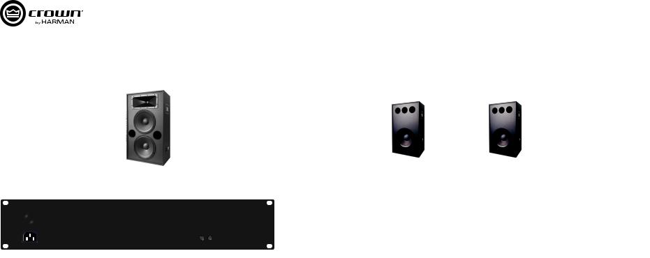
Thank you for purchasing the Crown® XLC series amplifier. The XLC2500 and XLC2800 are specially designed for cinema applications. By connecting it to the Crown CXM2000 monitor and crossover system, you can monitor either the processor input signals or the amplifier output signals. You can also see the fault alarms directly on the CXM2000 front panel or TMS (Theater Management System) interface. Together with JBL BC series cinema speakers and Crown CXM2000, Crown XLC series amplifiers offer a perfect cinema audio solution.
|
FAULT |
|
|
CLIP |
XLC2500 |
|
|
|
|
SIGNAL |
|
CH 1 |
|
CH 2 |
FAULT
CLIP
SIGNAL
CH 1 |
CH 2 |
1.
XLC2800 


Crown XLC Crown XLC CXM2000CXM2000 CXM2000
TMS Crown XLC JBL Crown CXM2000
1.1 Features
•Two models of 500W (XLC2500) and 800W (XLC2800) per channel at 4 ohms.
•Compatible with JBL cinema speaker 3722(N), 4722(N), 3730, 3252(N), 4641, 4642A, 8320, 4181, 8281, 8340A, 8350, SCS8, SCS12 to deliver the high quality sound.
•Power for 2 ohm, 4 ohm and 8 ohm outputs, supporting stereo, parallel and bridge outputs.
•Volume control on rear panel.
•High performance, light weight class-D amplifier - weights less than 5kg (net weight).
•HD-15 and phoenix connectors make the system wiring easy.
•Indicators provide accurate diagnostics: Power, Signal, Clip and Fault.
•Compatible with Crown CXM2000 and DSi-8M for total audio system solution. Support the Crown CXM2000 for monitor, fault detection and crossover functions. Support the Crown DSi-8M for monitor function.
1.2 How to use this manual
This manual provides you with the necessary information to safely setup and correctly operate your amplifier. However, it does not cover every aspect of installation, setup or operation that might occur under every condition. For additional information, please consult Crown’s Amplifier Application Guide (available online at www.crownaudio.com), Crown Technical Support, your system installer, or the retailer where this amplifier was purchased.
We strongly recommend you read all instructions, warnings and cautions contained in this manual. Also, for your protection, please send in your warranty registration card today. And save your bill of sale — it’s your official proof of purchase.
1.1
•4 500W(XLC2500) 800W (XLC2800)
•JBL 3722(N) 4722(N) 3730 3252(N) 4641 4642A 8320 4181 8281 8340A 8350 SCS8 SCS12
•2/4/8
•D 5
•15 XLC /
• 现况。
•Crown CXM2000 DSi-8M Crown CXM2000 Crown DSi-8M
1.2
Crownwww.crownaudio.com Crown
|
|
|
|
Operation Manual |
|
page 5 |
|
|
XLC Series Power Amplifiers |
XLC |
2. Setup |
2. |
|
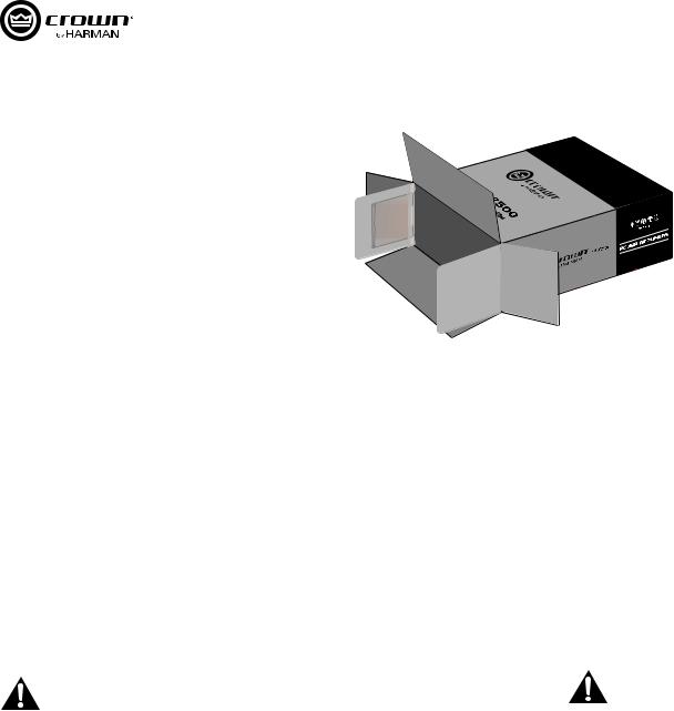
Figure 2.1 Package
2.1
2.1 Unpacking
Please unpack and inspect your XLC amplifier for any damage that may have occurred during transit. If damage is found, notify the transportation company immediately. Only you can initiate a claim for shipping damage, though Crown will be happy to help as needed. If the product arrived showing signs of damage, save the shipping carton for the shipper’s inspection.
We also recommend that you save all packing materials so you will have them if you ever need to transport the unit. Never ship the unit without the factory carton and packing materials.
Package contains:
•One XLC amplifier;
•One Power Cord (compatible to retailer’s location);
•One operation manual (this manual);
•One product registration form (at the end of this manual);
•One warranty card (at the end of this manual).
For installation, you will need (not supplied):
•Input wiring cables
•Output wiring cables
•Rack for mounting amplifier (or a stable surface for stacking)
NOTE: Before you start to set up your amplifier, make sure you read and observe the Important Safety Instructions found at the beginning of this manual.
2.1
尽管Crown
箱和包装材料的情况下装运设备。
•XLC
息。
page 6 Operation Manual |
|
XLC Series Power Amplifiers |
XLC |
|
2. Setup (continued) |
2. |
|
FAULT |
XLC2500 |
3.46 In. |
SIGNAL |
8.8 cm |
|
CLIP |
|
|
CH 1 |
CH 2 |
|
18.99 In. |
48.25 cm |
XLC2500
8.12 In.
20.65 cm
XLC2800
10.38 In. |
26.36 cm |
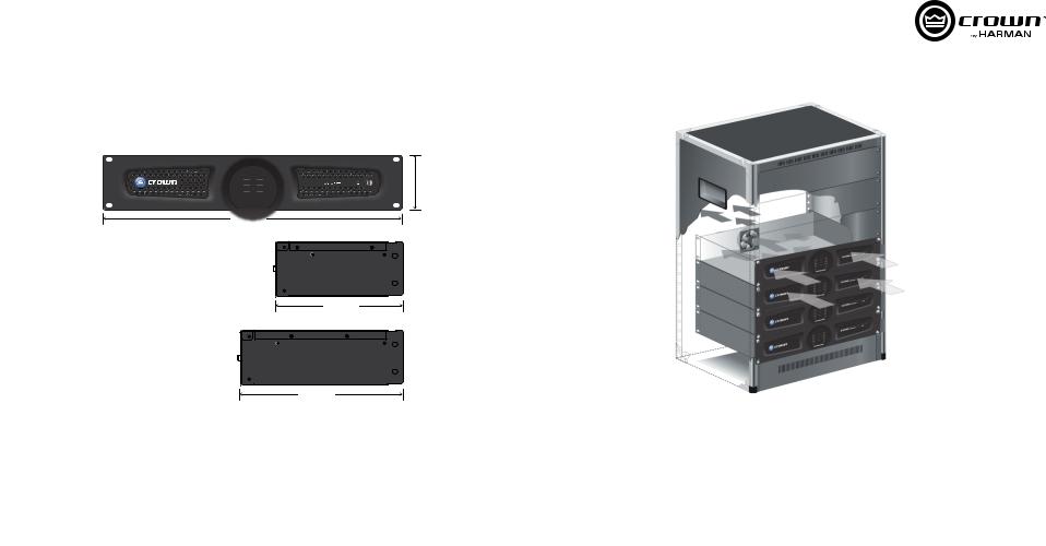
Figure 2.2 Dimensions
2.2
Figure 2.3 Airflow
2.3
2.2 Installing the amplifier
NOTE: Before you begin, make sure your amplifier is disconnected from the power source, with the power switch in the “off” position and all level controls turned completely down (counter-
clockwise).
Use a standard 19-inch (48.3 cm) equipment rack. See Figure 2.2 for amplifier dimensions. You may also stack amplifiers without using a cabinet.
NOTE: Amplifiers should be supported at both the front and rear of the rack.
2.2
19 48.3 2.2
2.3 Ensuring Proper Cooling
When using an equipment rack, mount units directly on top of each other. Close any open spaces in rack with blank panels. Do not block front or rear air vents. The back of the rack should be open.
Figure 2.3 illustrates standard amplifier airflow.
2.3
前面和后面的通风口。机架的后面应该保持开放。
2.3
|
|
|
|
Operation Manual |
|
page 7 |
|
XLC Series Power Amplifiers |
XLC |
2. Setup (continued) |
2. |
|
CXM2000 |
CXM2000 |
|
|
|
|
|
|
|
|
|
|
|
|
|
Firmware update |
RS-232 |
|
INPUTS FROM PROCESSOR OUTPUTS |
|
|
|
|
|
|
|
|
|
|
|
|
Firmware update |
RS-232 |
|
INPUTS FROM PROCESSOR OUTPUTS |
|
|
|
|
|
|
|
|
|
|
|
|
|
|
|
|
|
|
|
|
|
|
|
|
|
|
|
|
|
|||
|
Speaker |
1-4 |
L-Bi-amp |
R-Bi-amp |
C |
Sw1 |
Sw2 |
Ls/Rs |
Bsl/Bsr |
|
Speaker |
1-4 |
L-Bi-amp |
R-Bi-amp |
|
|
|
|
|
||||||||||||
230 |
System |
|
5-8 |
L&R-Passive |
Null-Passive |
230 |
C |
Sw1 |
Sw2 |
Ls/Rs |
Bsl/Bsr |
||||||||||||||||||||
|
|
|
|
|
|
|
|
|
|
|
|
|
|
|
System |
|
5-8 |
L&R-Passive |
Null-Passive |
||||||||||||
|
ON1 |
2 |
3 |
4 |
5 |
6 |
7 |
8 |
|
|
|
|
|
|
|
|
ON1 |
2 |
3 |
4 |
5 |
6 |
7 |
8 |
|
|
|
|
|
|
|
|
|
|
|
|
|
|
|
|
|
|
|
OUTPUTS TO POWER AMPLIFIER INPUTS |
|
|
|
|
|
|
|
|
|
|
|
||||||||
|
|
|
|
|
|
|
|
|
|
|
|
|
|
|
|
|
|
|
|
|
|
|
|
|
|
|
|
OUTPUTS TO POWER AMPLIFIER INPUTS |
|
|
|
XLC Series Amplifiers |
L Channel |
|
|
|
|
|
|
|
XLC Series Amplifiers |
L&R Channel |
|
|
|
|
|
|
|
||||||||||||||
|
R Channel |
|
|
|
|
|
|
|
|
C Channel |
|
|
|
|
|
|
|
||||||||||||||
|
C Channel |
|
|
|
|
|
|
|
|
SW1 Channel |
|
|
|
|
|
|
|
||||||||||||||
|
SW1 Channel |
|
|
|
|
|
|
|
|
SW2 Channel |
|
|
|
|
|
|
|
||||||||||||||
|
SW2 Channel |
|
|
|
|
|
|
|
|
Ls&Rs Channel |
|
|
|
|
|
|
|||||||||||||||
|
Ls&Rs Channel |
|
|
|
|
|
|
|
Bsl&Bsr Channel |
|
|
|
|
|
|
||||||||||||||||
|
Bsl&Bsr Channel |
|
|
|
|
|
|
|
|
|
|
|
|
|
|
|
|
|
|
|
|
|
|
||||||||
|
5 |
|
1 |
|
||
|
|
|
|
|
|
|
|
|
|
|
|
|
|
|
|
|
|
|
|
|
|
|
|
|
|
|
|
|
|
|
10 |
|
|
6 |
|
15 |
|
11 |
|
||
|
|
|
||||
Pin |
CXM2000 |
Crown XLC series |
||||
|
|
|
||||
1 |
CH1 Output - |
CH1 Input - |
||||
|
|
|
||||
2 |
Null |
Null |
||||
|
|
|
||||
3 |
V-MON CH1 Input |
V-MON CH1 |
||||
|
|
|
||||
4 |
CH1 Amp status |
CH1 Amp status |
||||
|
|
|
||||
5 |
CH1 Load Current status |
CH1 Load Current status |
||||
|
|
|
||||
6 |
Sig GND |
Sig GND |
||||
|
|
|
||||
7 |
CH1 Output + |
CH1 Input + |
||||
|
|
|
||||
8 |
CH2 Output + |
CH2 Input + |
||||
|
|
|
||||
9 |
Null |
Null |
||||
|
|
|
||||
10 |
Chassis GND |
Chassis GND |
||||
|
|
|
||||
11 |
CH2 Output - |
CH2 Input - |
||||
|
|
|
||||
12 |
Null |
Null |
||||
|
|
|
||||
13 |
V-MON CH2 |
V-MON CH2 |
||||
|
|
|
||||
14 |
CH2 Amp status |
CH2 Amp status |
||||
|
|
|
||||
15 |
CH2 Load Current status |
CH2 Load Current status |
||||
|
|
|
|
|
|
|
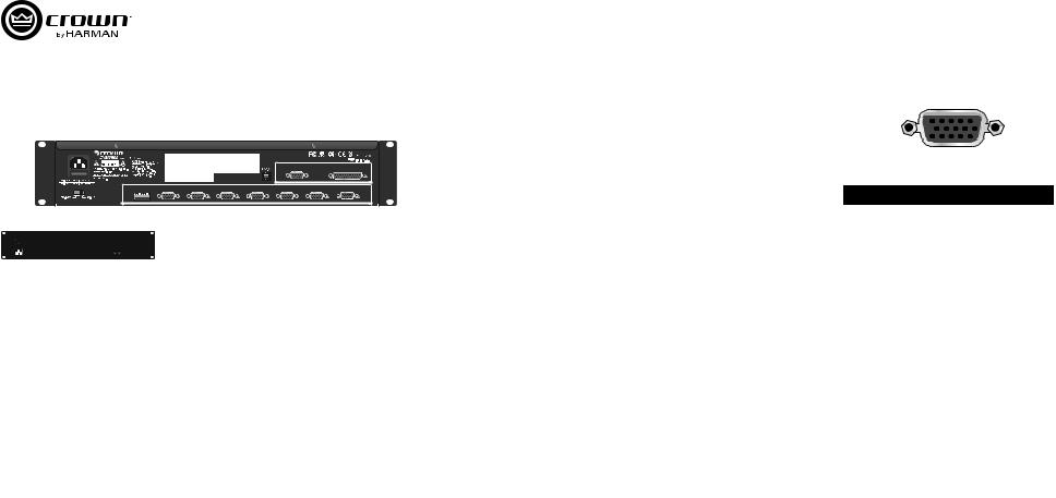
Figure 2.4 Wiring XLC Amplifiers to the CXM2000 in Bi-amplified Cinema Speakers System |
Figure 2.5 Wiring XLC Amplifiers to the CXM2000 in Passive Cinema Speakers System |
Figure 2.6 HD15 Pin Definition |
2.4 XLC CXM2000 |
2.5 XLC CXM2000 |
2.6 15 |
2.4 Wiring to the CXM2000 Monitor and Crossover System |
2.4 CXM2000 / |
|
It is recommended to use the XLC Series amplifiers with the Crown CXM2000 Monitor and Crossover System. Figure 2.4 and figure 2.5 are the samples of wiring XLC amplifiers to the CXM2000 in bi-amplified cinema speakers system and passive cinema speakers system through cables. This allows the CXM2000 to send the audio signals to and receive signals from the XLC amplifiers for crossover, fault detection and monitor functions. More details about the wiring, please read the Operation Manual of the CXM2000 Monitor and Crossover System.
Please see figure 2.6 for the HD-15 pin definition.
XLC Crown CXM2000 / 2.4 2.5 15 CXM2000 CXM2000 XLC CXM2000/
15 2.6
page 8 Operation Manual |
|

XLC Series Power Amplifiers |
XLC |
|
2. Setup (continued) |
2. |
|
Tab A
Tab B
Non-touch cover
|
|
|
|
|
|
|
|
|
|
|
|
|
|
|
|
|
|
|
|
|
|
|
|
|
|
|
|
|
|
|
|
|
|
|
|
|
|
|
|
|
|
|
|
|
|
|
|
|
|
|
|
|
|
|
|
|
|
|
|
|
|
|
|
|
|
|
|
|
|
|
|
|
|
|
|
|
|
|
|
|
|
|
|
|
|
|
|
|
|
|
|
|
|
|
|
|
|
|
|
|
|
|
|
|
|
|
|
|
|
|
|
|
|
|
|
|
|
|
|
|
|
|
|
Tab |
|
B |
Non-touch cover |
|
|
||
|
|
|
|
|
|
|
|
|
|
|
|
|
|
|
Tab A |
||||||
|
|
|
|
|
|
|
|
|
|
|
|
|
|
|
|
|
|
|
|
|
|
|
Figure 2.7 Input Wire and Connectors |
|
|
Figure 2.8 Output Wire and Connectors |
|
|
Figure 2.9 Non-Touch Cover and Its Position |
||||||||||||||
|
2.7 |
|
|
2.8 |
|
|
2.9 |
|
|||||||||||||
2.5 Alternative: Choosing Phoenix Connectors as Input Connectors
Besides connecting the XLC amplifiers to the CXM2000 through HD-15 connector, you can also connect to other input devices through the phoenix connectors on its rear panel. Crown recommends using pre-built or professionally wired balanced line (two-conductor plus shield), 22-24 gauge cables and connectors (see Figure 2.7). Unbalanced lines may be used, but may result in hum or RF noise over long cable runs.
 NOTE: Custom wiring should only be performed by qualified personnel.
2.5
HD-15 XLC CXM2000Crown 22-242.7
2.6Choosing Output Wiring and Connectors
Crown recommends using pre-built or professionally wired, high-quality, two-conductor, heavy gauge speaker wire and spade lug connectors or bare wire for your output connectors (Figure 2.8). To prevent the possibility of short-circuits, wrap or otherwise insulate exposed loudspeaker cable connectors.
Non-Touch cover provides protection of electric shock from the output terminals. Remove it to connect the cables to the output terminals and reinstall it when finish. To reinstall it, insert tab A into the slot right beside the output terminals (see figure 2.9). Put the screw through tab B and screw it into the hole left beside the output terminals (see figure 2.9).
Below are the suggested guidelines to select the appropriate size of wire based on the distance from amplifier to speaker.
Distance Wire |
Size |
|
Distance Wire |
Size |
|
|
|
|
|
up to 25 ft. |
16 AWG |
|
61-100 ft. |
10 AWG |
|
|
|
|
|
26-40 ft. |
14 AWG |
|
101-150 ft. |
8 AWG |
|
|
|
|
|
41-60 ft. |
12 AWG |
|
151-250 ft. |
6 AWG |
|
|
|
|
|
CAUTION: Never use shielded cable for output wiring.
NOTE: Custom wiring should only be performed by qualified personnel. Class 2 output wiring is required.
2.6
Crown 2.8
A2.9 B 2.9
|
|
|
|
|
|
|
|
|
|
25 |
16 AWG |
|
61-100 |
10 AWG |
|
|
|
|
|
26-40 |
14 AWG |
|
101-150 |
8 AWG |
|
|
|
|
|
41-60 |
12 AWG |
|
151-250 |
6 AWG |
|
|
|
|
|
2
|
|
|
|
Operation Manual |
|
page 9 |
|
|
|
|
XLC Series Power Amplifiers |
XLC |
|
|
|
|
|
||||||||||||
2. Setup (continued) |
|
|
|
|
|
|
|
|
2. |
|
|
|
|||||||||
|
|
|
- |
|
|
|
|
|
|
JBL 4181 |
|
JBL 4181 |
|
|
|||||||
Ch. 2 amplifier output to HF |
+ |
|
|
|
|
|
|
+ |
|
|
|
+ |
|
|
|
|
|||||
|
|
|
|
|
|
|
|
|
|
|
|
|
|
|
|
||||||
and MF driver |
|
|
|
|
|
|
|
|
|
|
|
|
|
|
|
|
|||||
|
|
|
|
|
|
|
|
|
|
|
|
|
|
|
|
|
|
|
|||
|
|
|
JBL 3252 |
|
|
|
|
|
- |
|
|
|
- |
|
|
|
|
||||
|
|
|
|
|
|
|
|
|
|
|
|
|
|
|
|
|
|
||||
|
|
|
|
+ |
|
Stereo: 1-OFF, 2-OFF |
|
|
|
|
|
|
|
|
|
|
|
||||
|
|
|
- |
|
|
|
|
|
|
|
|
|
|
|
|
|
|
|
|
||
|
|
|
|
|
ON |
|
|
|
|
|
|
|
|
Parallel: 1-ON, 2-OFF |
|||||||
|
|
|
|
|
|
|
|
|
|
|
|
|
|
|
|||||||
|
|
|
|
|
|
|
|
|
|
|
|
|
|
|
|
|
|
|
|
|
|
|
|
|
|
|
|
|
|
1 |
2 |
|
|
|
|
|
|
|
|
|
|
ON |
|
|
|
|
|
|
|
|
|
|
|
|
|
|
|
|
|
|
|
|
|
|
|
|
|
|
|
|
|
|
|
|
|
|
|
|
|
|
|
|
|
|
1 |
2 |
|
|
|
|
|
|
Ch. 1 amplifier output to LF driver |
|
|
|
|
|
|
|
|
|
|
|
|
|
|
|
|
|
T |
|
T |
|
S |
|
S |
|
U |
|
U |
|
A |
|
A |
|
H |
|
H |
|
X |
|
X |
|
E |
|
E |
|
R |
|
R |
|
I |
|
I |
|
A |
|
A |
|
T |
|
T |
|
O |
|
O |
|
H |
|
H |
|
Ch. 2 Source |
Ch. 1 Source |
Ch. 1 Source |
|
|
|
|
Figure 2.10 Stereo Mode |
Figure 2.11 Parallel Mode |
||
2.10 |
|
2.11 |
|
2.7 |
Wiring Your System |
2.7 |
|
2.7.1 |
Stereo Mode |
2.7.1 |
|
Typical input and output stereo wiring is shown in figure 2.10. If you need to know which frequence (high, middle or low) |
2.10 1 2 |
||
that the Channel 1 or Channel 2 corresponds to, please refer to the appendix in the operation manual of CXM2000. |
CXM2000 |
||
1. |
Set the Mode Switch to Stereo (1-OFF, 2-OFF). |
1. |
1-OFF, 2-OFF) |
2. |
Connect Channel 1 loudspeaker’s positive (+) lead to Channel 1 positive (red) terminal of amp; repeat for negative |
2. |
1 + 1 |
|
(-). Repeat Channel 2 wiring as for Channel 1. |
|
1 1 2 |
2.7.2 |
Parallel Mode |
2.7.2 |
|
Typical input and output bridge wiring is shown in figure 2.11. |
2.11 |
||
1. |
Set the Mode Switch to Parallel (1-ON, 2-OFF). |
1. |
1-ON, 2-OFF) |
2. |
Connect Channel 1 loudspeaker’s positive (+) lead to Channel 1 positive (red) terminal of amp; repeat for negative |
2. |
1 + |
|
(-). Repeat Channel 2 wiring as for Channel 1. |
|
1 1 2 |
page 10 Operation Manual |
|
 Loading...