

Crown Audio PZM-11, PZM-11LL User Manual
PZM®-11
PZM-11LL
POLAR
PATTERN
PRESSURE ZONE
MICROPHONES
he Crown® PZM®-11 or PZM-11LL is a
Pressure Zone Microphone® designed for
T
conference-room, security and surveillance
applications. Each can be mounted in the ceiling or
wall in a standard electrical outlet box. Providing
excellent intelligibility, the PZM-11 and
PZM-11LL are designed to look like a light switch
so as not to draw attention.
The PZM-11 has a mic-level output and is powered
by 12-48V phantom power.
The PZM-11LL has a line-level output and can be
powered by 24V AC, 12-24V DC, or 12-48V phantom power. Since the PZM-11LL has a high output,
it can be plugged directly into a VCR line input—no
costly mic preamp is needed.
To phantom power the PZM-11LL, a modifi cation
will have to be made to the electronics module (see
Installation Step 3 for details).
Like other Pressure Zone Microphones, the
PZM-11and PZM-11LL utilize the Pressure Recording Process
™
in which a miniature condenser
microphone capsule is mounted very close to a
sound-refl ecting plate or boundary. The capsule
is mounted in the “Pressure Zone” just above the
boundary, a region where sound coming directly
from the sound source combines in-phase with
sound refl ected off the boundary. The benefi ts are
a wide, smooth frequency response free of phase
interference, excellent clarity and “reach,” and consistent pickup anywhere around the microphone.
In the PZM-11and PZM-11LL, low frequencies
below the voice range are rolled off to reduce
pickup of air-conditioning rumble. The high-frequency response is boosted slightly to aid clarity
and articulation.
The microphone connector is a row of screw terminals for easy installation. The output is balanced,
low impedance, which allows long cable runs
without hum pickup or high-frequency loss.
Installation
1. Please refer to Fig. 3 (PZM-11) or Fig. 4 (PZM11LL) and locate all the parts shown.
2. Run a 2-conductor shielded mic cable to the
hole where you intend to install the microphone.
Install a standard electrical outlet box in the hole.
To use phantom power, you need a mixer with
phantom power or an external phantom-power
supply. Crown makes a PH-1A phantom power
supply which has 1 channel and is AC-adapter
powered.
(Continued on back)
Features
• Ideal for security, surveillance and conferrence rooms
• Clear, articulate sound
Specifi cations
Type: Pressure Zone Microphone.
Element: Electret condenser.
Frequency response (typical): 80 Hz to 20,000 Hz.
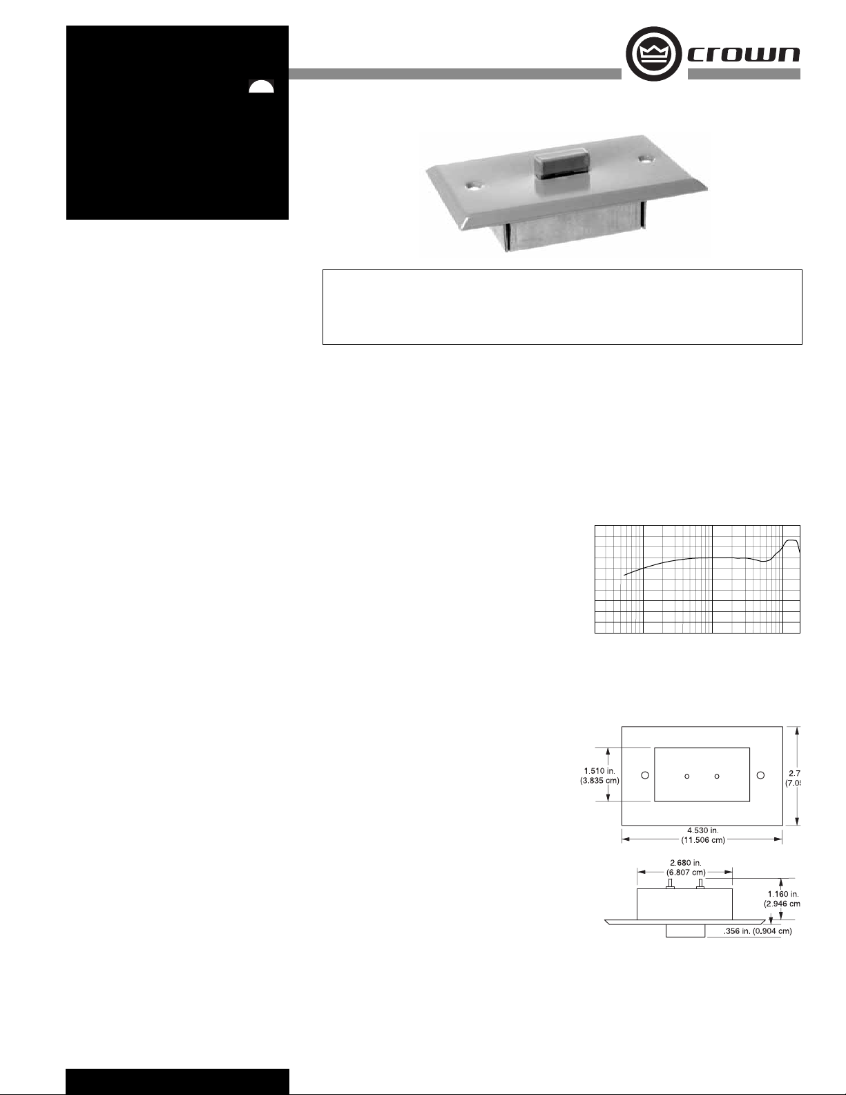
See Fig. 1.
Polar pattern: Hemispherical.
Impedance:
PZM-11: 225 ohms, balanced.
PZM-11LL: 75 ohms, balanced.
Recommended minimum load impedance 1000
ohms.
Open circuit sensitivity:
PZM-11: 5 mV/Pa* (–46 dBV/Pa).
PZM-11LL: 1.4V/Pa* (+3 dB re 1V/Pa).
Power sensitivity:
PZM-11: –45.5 dBm/Pa*
PZM-11LL: +8 dBm/Pa*.
Equivalent noise level (self-noise): 26 dB SPL typi-
cal (0 dB = .0002 dyne/cm
S/N Ratio: 68 dB at 94 dB SPL.
Maximum SPL:
PZM-11: 120 dB SPL produces 3% THD.
PZM-11LL: 100 dB SPL produces 3% THD.
Output connector: Three screw terminals.
1 = ground, 2 = audio hot (in polarity),
3 = audio cold (opposite polarity).
Polarity: Positive pressure on the diaphragm pro-
duces a positive voltage on screw terminal 2 with
respect to screw terminal 3.
Operating voltage:
PZM-11: Standard phantom power, 12 to 48V DC
on screw terminals 2 and 3 with respect to screw
terminal 1.
PZM-11LL: 24V AC, 12-24V DC, or phantom
power as the PZM-11LLS2.
Current drain:
PZM-11: 400 microamperes.
PZM-11LL: 4 milliamperes.
Materials: Steel plate and high-impact plastic
capsule holder.
Finish: Off-white. May be painted any color; take
care to fi rst seal the opening between the mic
capsule and boundary plate.
Operating Temperature Range: –10° to +60° C
(+14° to +140° F).
2
), A-weighted.
• Low-impedance screw-terminal output
• Inconspicuous
• PZM-11 is mic level; PZM-11LL is line level
Net weight: 2.5 oz. (71 g).
Dimensions: See Fig. 2.
Optional accessories: Crown PH-1A phantom power
supply (1 channel, AC-adapter powered).
*1 pascal = 10 dynes/cm2 = 10 microbars = 94 dB SPL.
Fig. 1. Frequency Response
+15
+10
+5
dB 0
5
10
15
20
25
30
35
20 100 1K
Fig. 2.
Dimensions
Frequency in Hz
10K
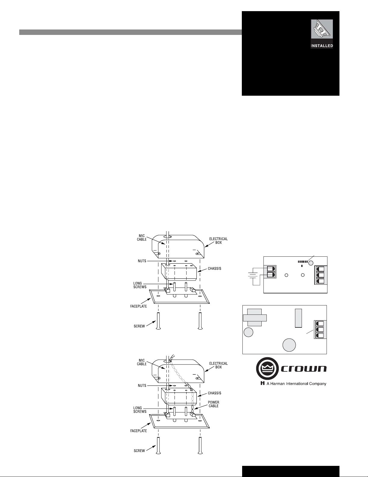
3. This entire step is for the PZM-11LL only. The
PZM-11LL can be powered in three ways: 24V AC,
12-24V DC, or 12-48V phantom power. The mic
is factory-wired for 24V AC powering so that it is
compatible with video surveillance systems where
24V AC is readily available.
To use phantom power with the PZM-11LL: Put
R14 in R13’s space; put R15 in R16’s space (the
resistors are labeled on the circuit board). Note: In
some cases these resistors may be on the bottom
side of the board. Do not overheat. Then proceed
to step 4.
To use 24V AC or 12-24V DC with the PZM-11LL:
From your power source, run a twisted pair of
power cable to the ceiling or wall hole. Run the
power cable through the hole in the electrical box
(if any) and through either hole in the chassis (Fig.
4). Service the end of the power cable.
To use 24V AC with the PZM-11LL: Attach the
power leads to the screw terminals labeled 24V AC
INPUT.
To use 12-24V DC with the PZM-11LL: See
Fig. 5. Connect the positive lead from the DC
source to either screw terminal of the INPUT terminal block. Connect the negative lead to the other
terminal of the INPUT terminal block.
4. Run the mic cable through the hole in the
electrical box (if any) and through either hole in the
chassis (Fig. 4). Service the end of the mic cable.
5. Attach your mic-cable leads to the screw terminals labeled OUTPUT. Connect the mic-cable shield
to 1, audio + lead to 2, and audio – lead to 3. See
Figures 5 and 6.
6. Place the chassis over the two long screws.
Using the nuts provided, secure the chassis to the
faceplate.
7. Using the two screws provided, secure the
faceplate to the electrical box or wall board.
8. If you plan to use an XLR-type cable connector:
Solder the cable shield to pin 1, audio + lead to pin
2 and audio – lead to pin 3 of the XLR.
If you plan to use an RCA or phone connector:
Solder the cable shield to the long lug, and solder
the audio + lead to the tip or pin. Do not connect
the audio – lead because this may reduce the
output level in an unbalanced confi guration.
9. If the mic cable is run in metal conduit, ground
loops can occur that can cause hum. If hum is
present after installation, unsolder the chip resistor
labeled 000 on the printed-circuit board (R21 GND
LIFT in Fig. 5).
10. If you plan to use a cable connector, solder the
other end of the mic cable to a 3-pin professional
audio connector (XLR-type). Solder the cable
shield to pin 1, light-colored lead to pin 2, and
darker lead to pin 3.
If the PZM-11LL distorts, change resistor R5
labeled GAIN to increase headroom. Do not overheat. The surface-mount resistors listed below
are already on the circuit board. See Fig. 5.
1K minimum headroom
2K 6 dB more headroom
3.9K 12 dB more headroom
8.2K 18 dB more headroom
100K maximum headroom
(mic level)
Architects’ and Engineers’ Specifi cations
PZM-11
The microphone shall be the Crown Model
PZM-11. The microphone shall be a Pressure Zone
Microphone, electret-condenser type, with built-in
electronics interface. The microphone capsule
holder shall be mounted on a standard switch
plate. The microphone shall be powered from
12-48V phantom power. The output shall be low
impedance balanced. Frequency response shall be
from 80 Hz to 20,000 Hz. Low frequencies below
the voice range shall be rolled off. Open-circuit
sensitivity shall be 5 mV/Pa (–46 dB re 1V/Pa).
Maximum SPL capability shall be 120 dB SPL at
3% THD. Equivalent noise shall be 26 dBA typical
(0 dB = .0002 dyne/cm
11 microphone is specifi ed.
PZM-11LL
The microphone shall be the Crown model
PZM-11LL. It shall be a Pressure Zone Microphone, mountable in a wall or ceiling, and designed
not to look like a microphone. It shall have a linelevel output (1.4 V/Pa unloaded) and be powered
by 24V AC, 12-24V DC, or phantom power. The
frequency response shall be from 80 Hz to 20,000
Hz with a low-frequency rolloff to reduce rumble
and high-frequency boosdt for articulation. The
Fig. 3.
Wiring for Phantom Power
Fig. 4. PZM-11LL Wiring for 24V AC or
12-24V DC
2
). The Crown model PZM-
PZM-11
PZM-11LL
audio connector and power connector shall be
screw terminals. Output shall be balanced, low
impedance. The electret condenser transducer
shall have a hemispherical polar pattern when the
microphone is mounted in a wall or ceiling. The
Crown PZM-11LL microphone is specifi ed.
Warranty
Crown professional microphones are guaranteed
against malfunction for a period of three years
from date of original purchase. See enclosed warranty sheet for additional information.
Service
If the unit fails to work, fi rst replace or repair
the mic cables and check the power supply.
Recheck your connections to the microphone
screw terminals. If service is required, return the
microphone and the electronic interface in its
original packaging to: Crown Factory Service,
1718 West Mishawaka Road, Elkhart, IN 46517-
9439. A Service Return Authorization (SRA) is
required for product being sent to the factory
for service. An SRA can be completed on line at
www.crownaudio.com/support/factserv.htm. For
further assistance or technical support call 800342-6939.
Fig.5. PZM-11LL DC Powering and Output Wiring
12 to
24VDC
PZM-11 Output Wiring
Fig.6.
OUTPUT
SCREW
TERMINALS
Crown International, Inc.
1718 W. Mishawaka Rd.
Elkhart, IN 46517-9439
TEL: 574-294-8000
FAX: 574-294-8FAX
www.crownaudio.com
©
2008 Crown Audio®, Inc. Specifi cations subject to change
without prior notice. Latest information available at www.
crownaudio.com. Crown, Crown Audio, PZM and Pressure Zone Microphone are registered trademarks of Crown
International. Pressure Recording Process is a trademark of
E. M. Long Associates.
6/08 136455-6
GND
LIFT
GAIN
R5
GND 1
AUDIO – 3
AUDIO + 2
AUDIO – 3
AUDIO + 2
GND 1
 Loading...