

Page 1
XTi2 Series Operation Manual
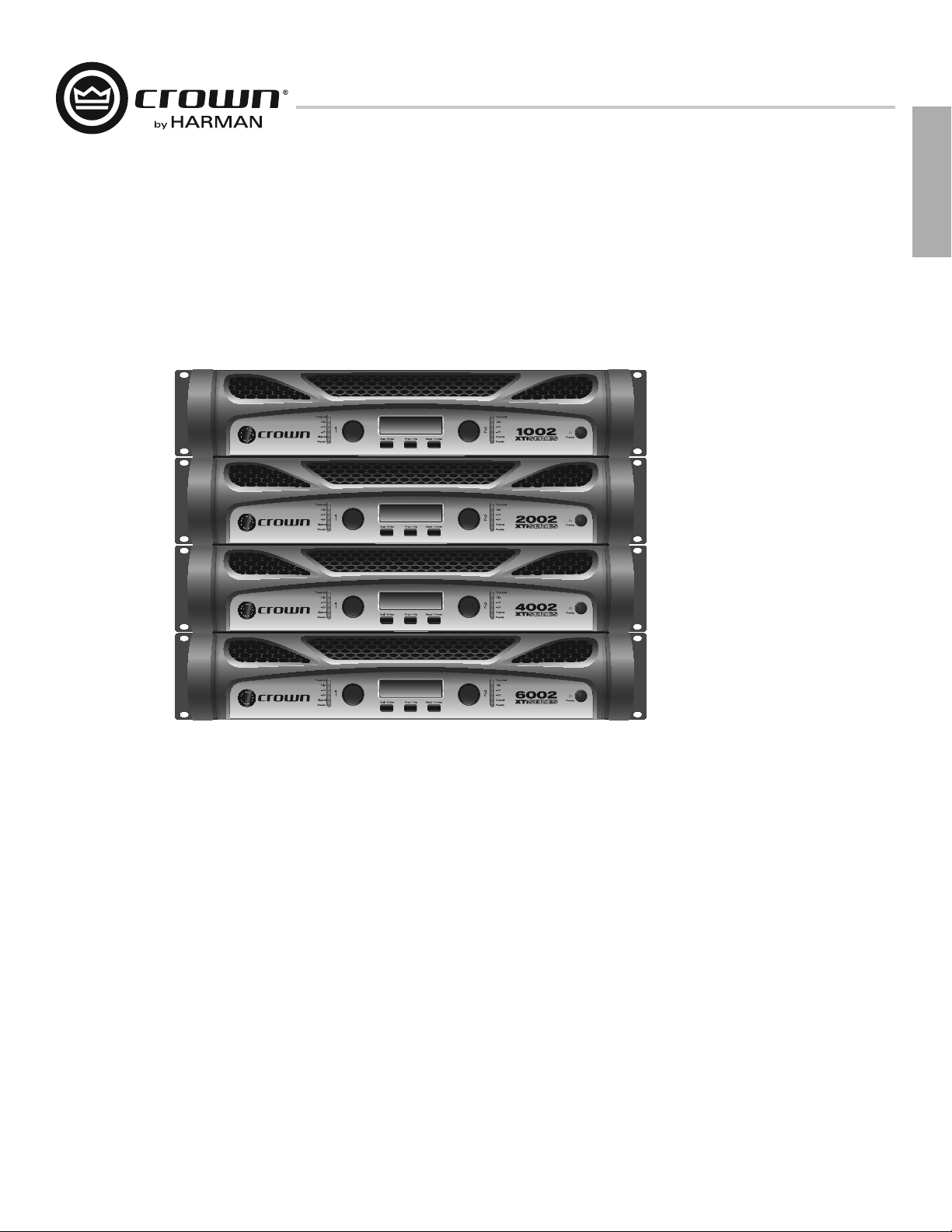
XTi 1002
XTi 2002
XTi 4002
XTi 6002
Obtaining Other Language Versions: To obtain information in another language about the use of this product, please contact your local Crown Distributor. If you need
assistance locating your local distributor, please contact Crown at 574-294-8000.
This manual does not include all of the details of design, production, or variations of the equipment. Nor does it cover every possible situation which may arise during
installation, operation or maintenance.
The information provided in this manual was deemed accurate as of the publication date. However, updates to this information may have occurred. To obtain the latest
version of this manual, please visit the Crown website at www.crownaudio.com.
Trademark Notice: Crown, Crown Audio, and Amcron are registered trademarks of Crown International. Other trademarks are the property of their respective owners.
Later versions of this manual and additional information about this product may be available at the Crown website at www.crownaudio.com.
Some models may be exported under the name Amcron
©2011 by Harman International, 1718 W. Mishawaka Rd., Elkhart, Indiana 46517-9439 U.S.A. Telephone: 574-294-8000.
®
143060-2 - 4/11
Page 2

Important Safety Instructions
XTi2 Series Power Amplifiers
1. Read these instructions.
2. Keep these instructions.
3. Heed all warnings.
4. Follow all instructions.
5. Do not use this apparatus near water.
6. Clean only with a dry cloth.
7. Do not block any ventilation openings. Install in accordance with the
manufacturer’s instructions.
8. Do not install near any heat sources such as radiators, heat registers,
stoves, or other apparatus (including amplifiers) that produce heat.
9. Do not defeat the safety purpose of the polarized or grounding-type
plug. A polarized plug has two blades with one wider than the other.
A grounding-type plug has two blades and a third grounding prong.
The wide blade or the third prong is provided for your safety. If the
provided plug does not fit into your outlet, consult an electrician for
replacement of the obsolete outlet.
10. Protect the power cord from being walked on or pinched, particularly
at plugs, convenience receptacles, and the point where they exit from
the apparatus.
11. Only use attachments/accessories specified by the manufacturer.
12. Use only with a cart, stand, tripod, bracket, or table specified by the
manufacturer, or sold with the apparatus. When a cart is used, use
caution when moving the cart/apparatus combination to avoid injury
from tip-over.
13. Unplug this apparatus during lightning storms or when unused for
long periods of time.
14. Refer all servicing to qualified service personnel. Servicing is required
when the apparatus has been damaged in any way, such as powersupply cord or plug is damaged, liquid has been spilled or objects
have fallen into the apparatus, the apparatus has been exposed to rain
or moisture, does not operate normally, or has been dropped.
15. Use the mains plug to disconnect the apparatus from the mains.
16. WARNING: TO REDUCE THE RISK OF FIRE OR ELECTRIC SHOCK, DO
NOT EXPOSE THIS APPARATUS TO RAIN OR MOISTURE.
17. DO NOT EXPOSE THIS EQUIPMENT TO DRIPPING OR SPLASHING
AND ENSURE THAT NO OBJECTS FILLED WITH LIQUIDS, SUCH AS
VASES, ARE PLACED ON THE EQUIPMENT.
18. THE MAINS PLUG OF THE POWER SUPPLY CORD SHALL REMAIN
READILY OPERABLE.
TO PREVENT ELECTRIC SHOCK DO NOT REMOVE TOP OR BOTTOM
COVERS. NO USER SERVICEABLE PARTS INSIDE. REFER SERVICING TO
QUALIFIED SERVICE PERSONNEL.
TO COMPLETELY DISCONNECT THIS EQUIPMENT FROM THE
AC MAINS, DISCONNECT THE POWER SUPPLY CORD PLUG FROM THE
AC RECEPTACLE. THE MAINS PLUG OF THE POWER SUPPLY CORD
SHALL REMAIN READILY OPERABLE.
WATCH FOR THESE SYMBOLS:
The lightning bolt triangle is used to alert the user to the risk of electric
shock.
The exclamation point triangle is used to alert the user to important
operating or maintenance instructions.
IMPORTANT
XTi2 Series amplifiers require Class 2 output wiring.
MAGNETIC FIELD
CAUTION! Do not locate sensitive high-gain equipment such as
preamplifiers or tape decks directly above or below the unit. Because this
amplifier has a high power density, it has a strong magnetic field which can
induce hum into unshielded devices that are located nearby. The field is
strongest just above and below the unit.
If an equipment rack is used, we recommend locating the amplifier(s) in
the bottom of the rack and the preamplifier or other sensitive equipment at
the top.
FCC COMPLIANCE NOTICE
This device complies with part 15 of the FCC rules. Operation is subject
to the following two conditions: (1) This device may not cause harmful
interference, and (2) this device must accept any interference received,
including interference that may cause undesired operation.
CAUTION: Changes or modifications not expressly approved by the
party responsible for compliance could void the user’s authority to
operate the equipment.
NOTE: This equipment has been tested and found to comply with
the limits for a Class B digital device, pursuant to part 15 of the FCC
Rules. These limits are designed to provide reasonable protection
against harmful interference in a residential installation. This equipment
generates, uses, and can radiate radio frequency energy and, if not
installed and used in accordance with the instruction manual, may
cause harmful interference to radio communications. However, there is
no guarantee that interference will not occur in a particular installation.
If this equipment does cause harmful interference to radio or television
reception, which can be determined by turning the equipment off and
on, the user is encouraged to try to correct the interference by one or
more of the following measures:
t 3FPSJFOU PS SFMPDBUF UIF SFDFJWJOH BOUFOOB
t *ODSFBTF UIF TFQBSBUJPO CFUXFFO UIF FRVJQNFOU BOE SFDFJWFS
t $POOFDU UIF FRVJQNFOU JOUP BO PVUMFU PO B DJSDVJU EJGGFSFOU GSPN UIBU
to which the receiver is connected.
t $POTVMU UIF EFBMFS PS BO FYQFSJFODFE SBEJP57 UFDIOJDJBO GPS IFMQ
page 2
Operation Manual
Page 3

XTi2 Series Power Amplifiers
DECLARATION OF CONFORMITY
Issued By: Harman International.
1718 W. Mishawaka Rd.
Elkhart, IN 46517 U.S.A.
European Representative’s Name and Address:
David J. Budge
10 Harvest Close
Yateley
GU46 6YS
United Kingdom
Equipment Type: Power amplifiers
Family Name: XTi2 Series
Model Names: XTi1002, XTi2002, XTi4002, XTi6002
EMC Standards:
EN 55103-1:1997 Electromagnetic Compatibility – Product Family Standard for Audio, Video, Audio-Visual and Entertainment Lighting Control Apparatus for
Professional Use, Part 1: Emissions
EN 55103-1:1997 Magnetic Field Emissions-Annex A @ 10 cm and 1 M
EN 61000-3-2:2005 & Amd 1: 2008 Limits for Harmonic Current Emissions (equipment input current ≤16A per phase)
EN 61000-3-3:1998 Limitation of Voltage Fluctuations and Flicker in Low-Voltage Supply Systems Rated Current ≤16A
EN 55022:2006 Limits and Methods of Measurement of Radio Disturbance Characteristics of ITE: Radiated, Class B Limits; Conducted, Class B
EN 55103-2:1997 Electromagnetic Compatibility – Product Family Standard for Audio, Video, Audio-Visual and Entertainment Lighting Control Apparatus for
Professional Use, Part 2: Immunity
EN 61000-4-2:2001 Electrostatic Discharge Immunity (Environment E2-Criteria B, 4k V Contact, 8k V Air Discharge)
EN 61000-4-3:2006 Radiated, Radio-Frequency, Electromagnetic Immunity (Environment E2, Criteria A)
EN 61000-4-4:2007 Electrical Fast Transient/Burst Immunity (Criteria B)
EN 61000-4-5:2006 Surge Immunity (Criteria B)
EN 61000-4-6:2006 Immunity to Conducted Disturbances Induced by Radio-Frequency Fields (Criteria A)
EN 61000-4-11:2001 Voltage Dips, Short Interruptions and Voltage Variation
FOR FIELD SERVICE
QUESTIONS CALL: 1 800 342 6939
Safety Standard:
IEC 60065: 2001: 7Ed & Amd 1: 2005 Safety Requirements - Audio Video and Similar Electronic Apparatus
I certify that the product identified above conforms to the requirements of the EMC Council Directive 89/336/EEC as amended by 92/31/EEC,
and the Low Voltage Directive 73/23/EES as amended by 93/68/EEC.
Signed ______________________
Scott Potosky
Title: Director of Engineering Date of Issue: February 1, 2011
Operation Manual
page 3
Page 4
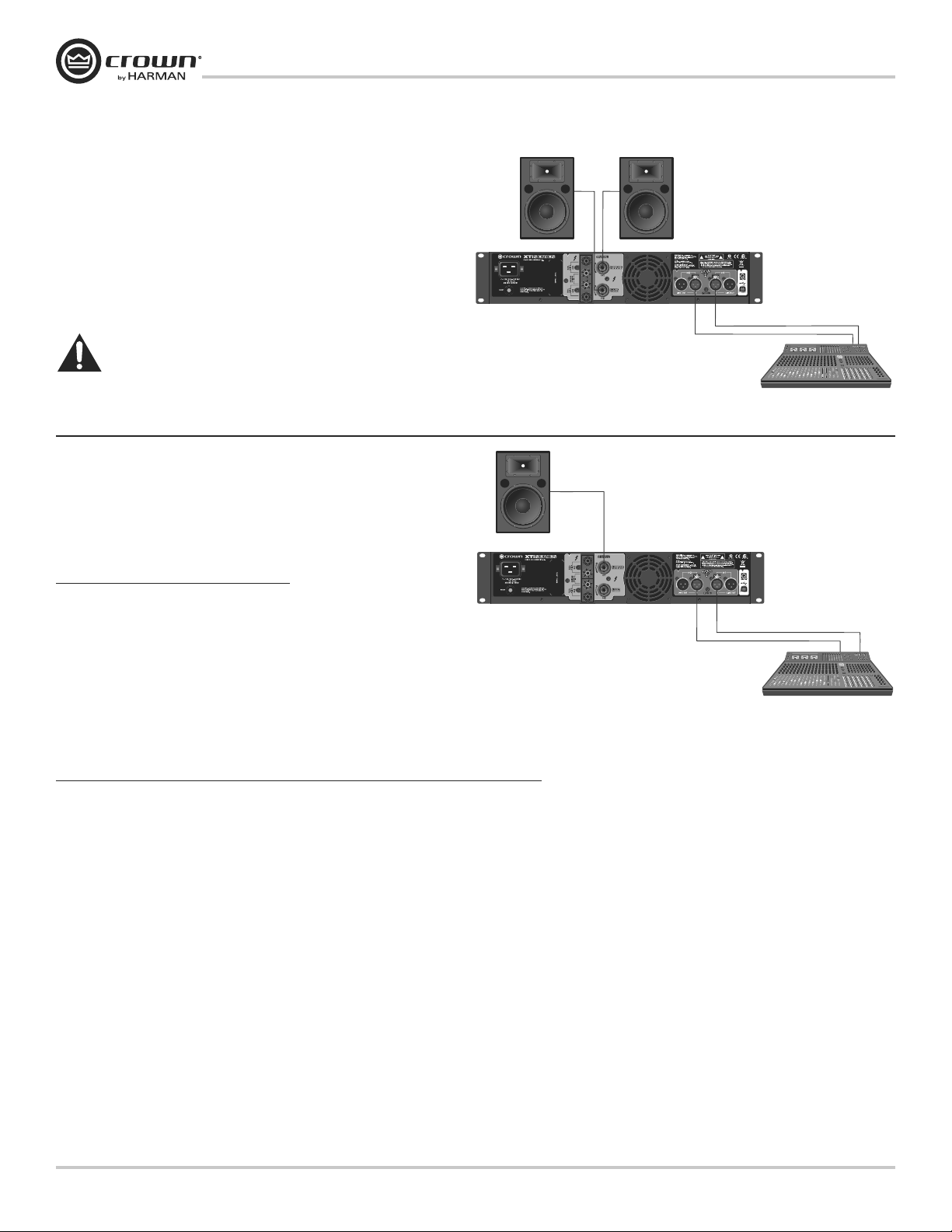
Get Started
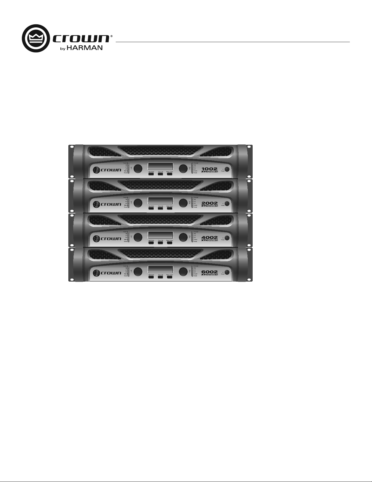
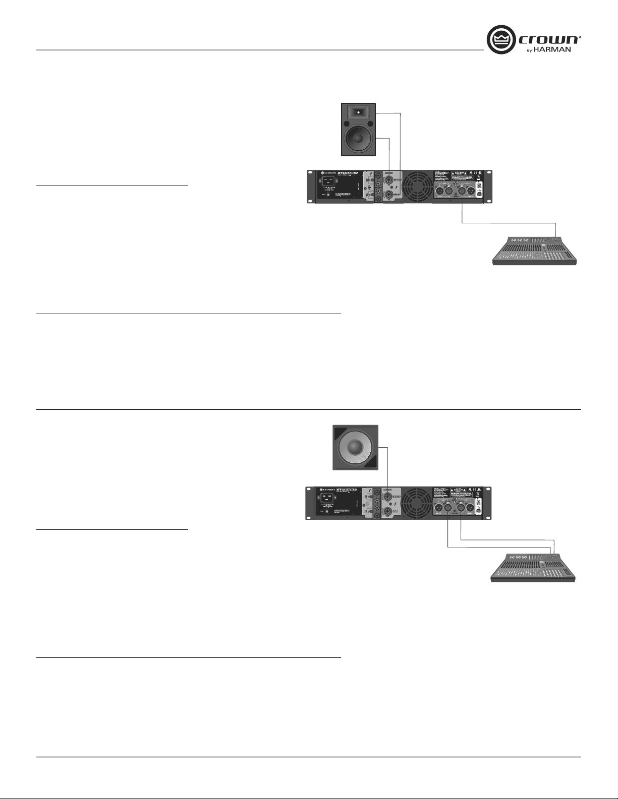
Stereo DSP Off
This is the default mode the amplifier is set to from the factory. The
amplifier is configured for stereo mode with all processing disabled.
1. Connect Left/Right signal source to Channel 1 and Channel 2 using
the XLR connectors.
®
2. Connect a speaker to each channel output using Speakon
Plugs, or bare wire.
WARNING: Before you start to set up your
amplifier, make sure you read and observe
the Important Safety Instruc tions found at
the beginning of this manual.
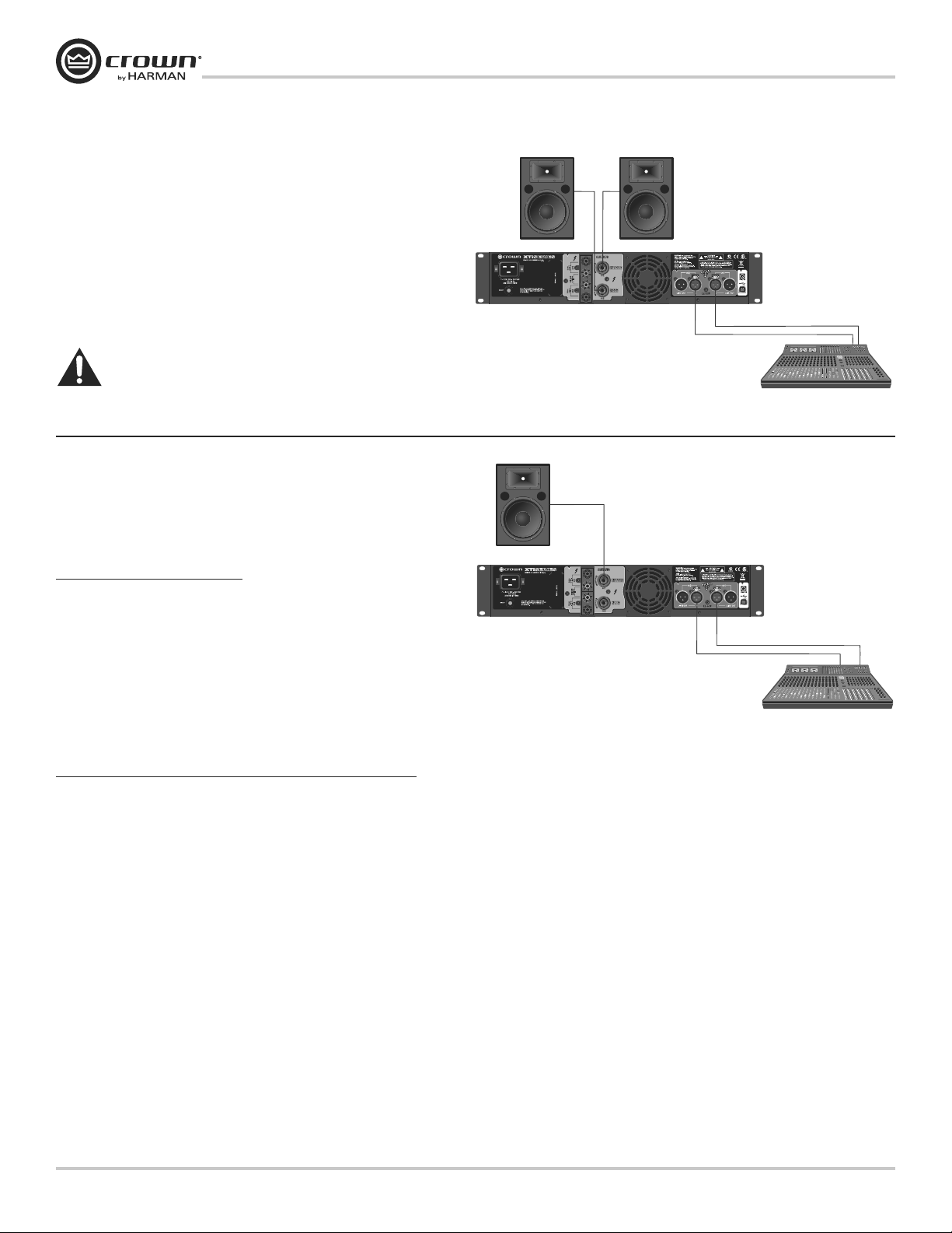
Factory Preset #2: BRIDGE
Putting the amplifier in BRIDGE (bridge-mono) mode delivers the power of
both amp channels into a single 8 or 4 ohm load. The XTi2 Series amplifiers
come pre-loaded with a preset that makes it easy to configure the amplifier for
this operation.
Before you get started ensure that you:
Connect signal source to Channel 1 and Channel 2 using XLR connectors
1.
(the amplifier inputs will automatically be summed together when
selecting this preset).
Connector the speaker as shown.
2.
If using the binding post outputs, connect the positive terminal of the speaker to the positive terminal of Channel 1 and
a.
the negative terminal of the speaker to the positive terminal of Channel 2.
If using a Speakon® connector, connect the positive terminal of the speaker to 1+ and the negative terminal to 2+. Plug the
b.
connector into the Channel 1 output only.
Follow these quick steps to configure the amplifier for BRIDGE operation:
Push the “Set/Enter” button and you will see the word “Preset” flashing.
1.
Push the “Set/Enter” button again to enter the list of presets in the amplifier.
2.
Push the “Next/Down” or “PREV/UP” button until the screen displays “Bridge”.
3.
4.
Push the “Set/Enter” button to confirm your selection.
The display will now read “Bridge” with the Y icon and Bridge icon highlighted.
5.
, Banana
XTi 6002 back panel shown.
See page 9 for XTi 1002,
2002 and 4002 back panel.
XTi2 Series Power Amplifiers
NOTE: Custom wiring should
only be performed by qualified
personnel.
page 4
Operation Manual
Page 5
XTi2 Series Power Amplifiers
Get Started
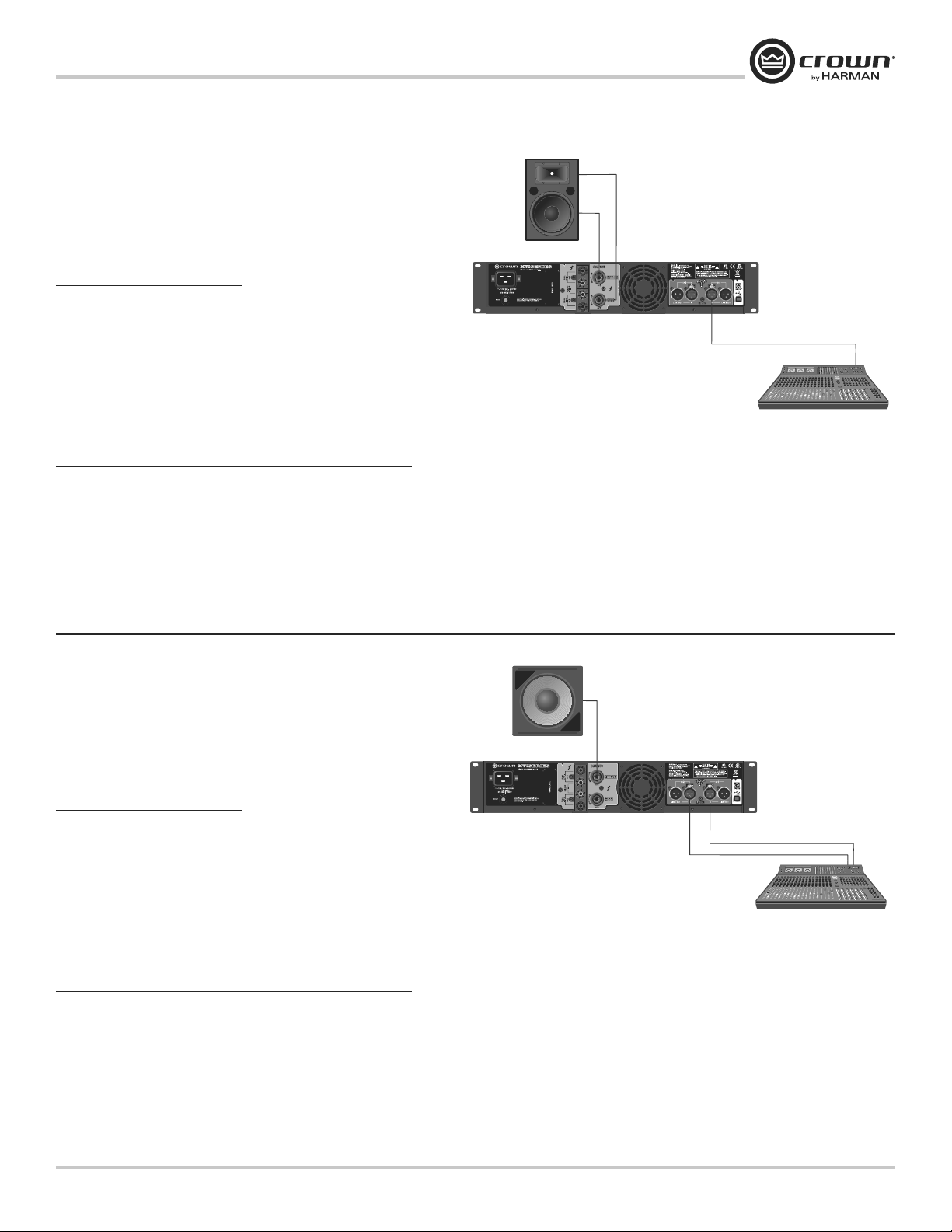
Factory Preset #3: XOVER
Putting the amplifier in XOVER mode enables a 1.2kHz 4th order (24dB/octave)
filter that sends frequencies of 1.2kHz and below to Channel 1 output and
frequencies of 1 2kHz and above to Channel 2 output. The XTi2 Series amplifiers
come pre-loaded with a preset that makes it easy to configure the amplifier for
this operation.
Before you get started ensure that you:
1. Connect signal source to Channel 1 ONL
amplifier inputs will automatically be put into Y mode when selecting this
preset).
2. Connector the speaker as shown.
a. Connect the speaker you wish to receive the low and mid frequencies (1.2kHz and below) to Channel 1 output
using Speakon
b. Connect the speaker you wish to receive the high frequencies (1.2kHz and above) to Channel 2 output using Speakon
Follow these quick steps to configure the amplifier for XOVER operation:
1. Push the “Set/Enter” button and you will see the word “Preset” flashing.
2. Push the “Set/Enter” button again to enter the list of presets in the amplifier.
3. Push the “Next/Down” or “PREV/UP” button until the screen displays “BIAMP”.
4. Push the “Set/Enter” button to confirm your selection.
5. The display will now read “BIAMP” with the Y icon and XOV icon highlighted.
®
, Banana Plugs, or bare wire.
Y using an XLR connector (the
HIGH 2+/–
LOW 1+/–
®
, Banana Plugs, or bare wire.
Factory Preset #4: BRG SUBS
Putting the amplifier in BRG SUBS (bridged subs) mode allows you to
bridge the amplifier for use with a single 8 or 4 ohm subwoofer. The inputs
are automatically summed, a 90Hz 4th order (24dB/octave) LowPass filter
is enabled, and the output mode is put into bridge-mono mode. The XTi2
Series amplifiers come pre-loaded with a preset that makes it easy to
configure the amplifier for this operation.
Before you get started ensure that you:
1. Connect signal source to Channel 1 and Channel 2 using XLR
connectors (the amplifier inputs will automatically be summed together
when selecting this preset).
2. Connector the speaker as shown.
a. If using the binding post outputs, connect the positive terminal of the
speaker to the positive terminal of Channel 1 and the negative terminal of the speaker to the positive terminal of Channel 2.
®
b. If using a Speakon
Follow these quick steps to configure the amplifier for XOVER operation:
1. Push the “Set/Enter” button and you will see the word “Preset” flashing.
2. Push the “Set/Enter” button again to enter the list of presets in the amplifier.
3. Push the “Next/Down” or “PREV/UP” button until the screen displays “XOVER”.
4. Push the “Set/Enter” button to confirm your selection.
5. The display will now read “XOVER” with the Y icon and XOV icon highlighted.
connector, connect the positive terminal of the speaker to 1+ and the negative terminal to 2+. Plug the connector into the Channel 1 output only.
Operation Manual
page 5
Page 6
Get StartedGet Started
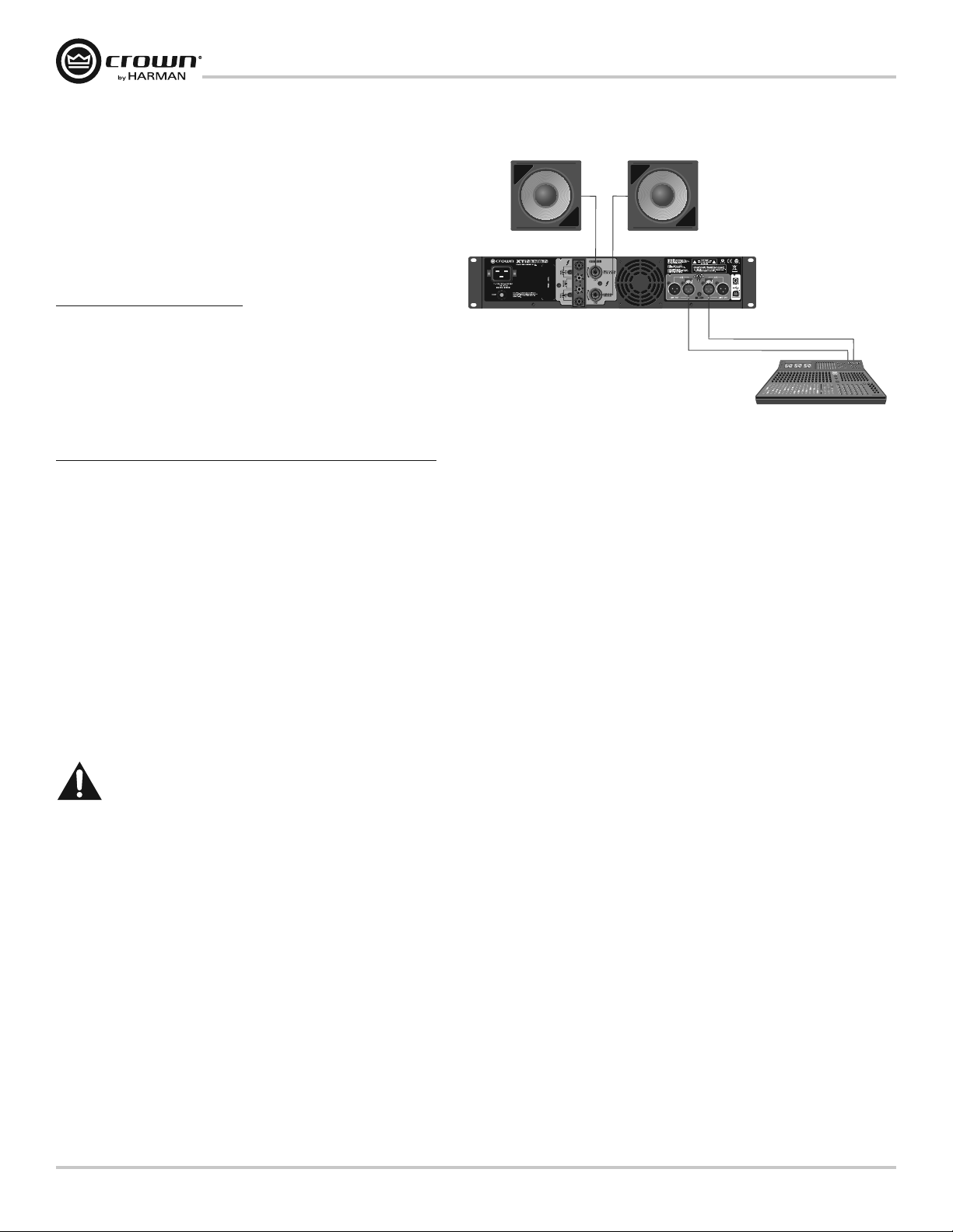
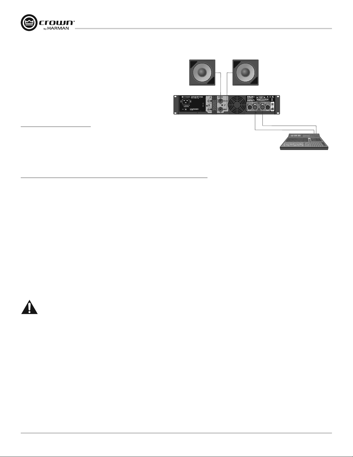
Factory Preset #5: SUBSYNTH
Putting the amplifier in SUBSYNTH mode allows you to turn on the
SubHarmonic Synth feature for use with a subwoofer on both channels. The
inputs are automatically summed, a 90Hz 4th order (24dB/octave) filter is
enabled on both Channel 1 and Channel 2, and the SubHarmonic Synth feature
is turned on at +12dB level. The XTi2 Series amplifiers come pre-loaded with a
preset that makes it easy to configure the amplifier for this operation.
Before you get started ensure that you:
Connect signal source to Channel 1 and Channel 2 using XLR connectors
1.
(the amplifier inputs will automatically be summed together when
selecting this preset).
Connector the speaker as shown.
2.
Connect a speaker to each channel output using Speakon©, Banana
a.
Plugs, or bare wire
Follow these quick steps to configure the amplifier for SUBSYNTH operation:
Push the “Set/Enter” button and you will see the word “Preset” flashing.
1.
Push the “Set/Enter” button again to enter the list of presets in the amplifier.
2.
Push the “Next/Down” or “PREV/UP” button until the screen displays “SUBSYNTH”.
3.
Push the “Set/Enter” button to confirm your selection.
4.
The display will now read “SUBSYNTH” with the Y icon and XOV icon highlighted.
5.
XTi2 Series Power Amplifiers
Ensure Proper Cooling
When using an equipment rack, mount units directly on top of each other. Close any
open spaces in rack with blank panels. DO NOT block front or rear air vents. The side
walls of the rack should be a minimum of two inches (5.1 cm) away from the amplifier
sides, and the back of the rack should be open.
CAUTION: Before you begin installing your amplifier, make sure
it is disconnected from the power source, with the power switch
in the “off” position and all level controls turned completely
down (counterclock wise).
page 6
Operation Manual
Page 7

XTi2 Series Power Amplifiers
Welcome
There’s no debate – when you choose Crown’s XTi2 Series, you’re choosing one of the most powerful and innovative amplifiers
on the market today. That’s because the all-new XTi2 Series amps continue to set the standard for unmatched performance and
value, delivering the goods night after night without breaking a sweat.
With such innovations as a universal tracking switch-mode power supply and a fully integrated suite of speaker processing
tools, these amps are at the top of their class when it comes to thermal efficiency and system flexibility.
You also have greatly improved control capabilities. The addition of Peak
threshold, attack and release, and we enhanced the Subharmonic Synth so you can easily manage frequency, gain and filter
type, allowing for application specific tuning.
Plus, you’ll now be able to tailor fan speed for specific applications with the new Advanced Thermal controls and have software
visibility of the Power Supply Temperature and AC Line Voltage with the new Advanced Monitoring controls. Combine all of
that with integrated cast-aluminum rack handles for maximum durability and portability and you have the power to move you –
and the world.
Plus™ Limiters gives you full command over
X
Next Generation Features include:
t 1FBL9 1MVT -JNJUFST QSPWJEF UIF VMUJNBUF JO TZTUFN QFSGPSNBODF BOE QSPUFDUJPO CZ BMMPXJOH
full control over threshold, attack, and release
t &OIBODFE 4VCIBSNPOJD 4ZOUI TFDUJPO QSPWJEFT VTFS DPOUSPM PWFS DSPTTPWFS GSFRVFODZ NBY IBSNPOJD GSFRVFODZ
and 1 PEQ filter for system-specific tuning
t /FX "EWBODFE 5IFSNBM DPOUSPMT BMMPX GPS VTFSEFmOFE GBO NPEF DPOUSPMT o OPSNBM FBSMZ
and full speed – for matching fan performance to a specific application
t /FX "EWBODFE .POJUPSJOH QSPWJEFT TPGUXBSF WJTJCJMJUZ PG UIF 1PXFS 4VQQMZ 5FNQFSBUVSF BOE "$ -JOF 7PMUBHF
t *ODSFBTFE OVNCFS PG QSFTFUT UP B UPUBM PG PG XIJDI BSF VTFS EFmOBCMF
t *OUFHSBUFE oDBTU BMVNJOVN IBOEMFT GPS FBTZ IBOEMJOH BOE FOIBODFE EVSBCJMJUZ
t -PDLJOH QPXFS DPSE DMJQ QSPWJEFT B TFDVSF DPOOFDUJPO CFUXFFO UIF BNQMJmFS BOE QPXFS DPSE
t 6QEBUFE )J2OFU #BOE .BOBHFS BOE 4ZTUFN "SDIJUFDU DPOUSPM TPGUXBSF
How to Use This Manual
This manual provides you with the necessary information to safely and correctly setup and operate your amplifier. It does
not cover every aspect of installation, setup, or operation that might occur under every condition. For additional information,
please consult Crown’s Amplifier Application Guide (available at www.crownaudio.com), Crown Technical Support, your
system installer or retailer.
We strongly suggest you read all instructions, warnings and cautions contained in this manual. Also, for your protection,
please send in your warranty registration card today. And save your bill of sale – it’s your official proof of purchase.
Operation Manual
page 7
Page 8
XTi2 Series Power Amplifiers
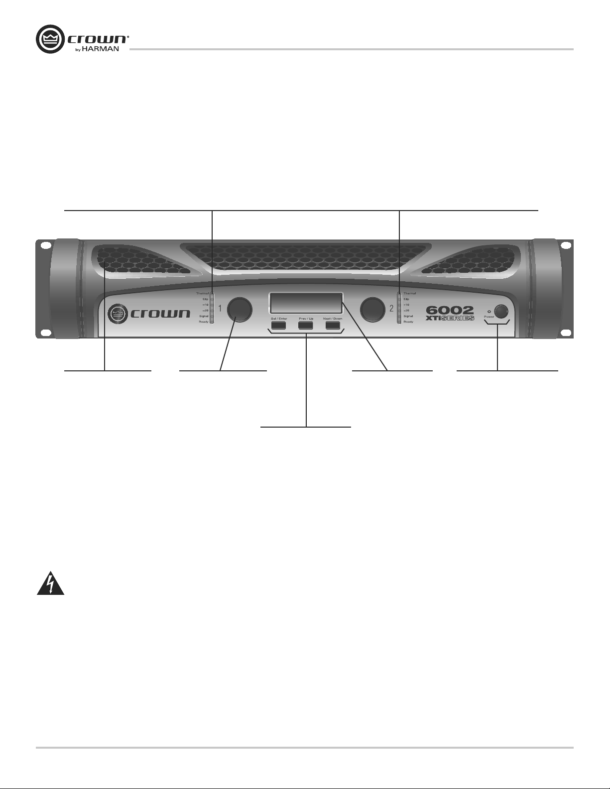
Front Panel Features
Indicators:
Ready Indicator: Two green LEDs, one for each channel, illuminate when the amplifier is ready to produce audio.
Signal Presence Indicator: Two green LEDs, one for each channel, illuminate when the channel input exceeds -40dBu. Useful for troubleshooting cable runs.
-20 Indicator: Two green LEDs, one for each channel, illuminate when the output signal exceeds -20dB below clip.
-10 Indicator: Two green LEDs, one for each channel, illuminate when the output signal exceeds -10dB below clip.
Clip Indicator: Two red LEDs, one for each channel, illuminate at the threshold of audible distortion.
Thermal Indicator: Two red LEDs, one for each channel, illuminate when thermal compression begins due to excessive temperature conditions.
Cooling Vents:
Front to rear forced air flow.
WARNING: Never connect the output to a power supply,
battery or power main. Electrical shock may result.
Gain (Level) Controls:
Two black rotary level controls,
one for each channel.
Sel/Prev/Next Buttons:
Three buttons located
underneath the LCD screen
used to access menu items
and front panel lockout.
LCD Screen:
Backlit liquid crystal display
shows enabled presets and
speaker processing.
Power Button & Indicator:
Turns amplifier power on and off.
Blue LED will illuminate when
power is turned on.
page 8
Operation Manual
Page 9
XTi2 Series Power Amplifiers
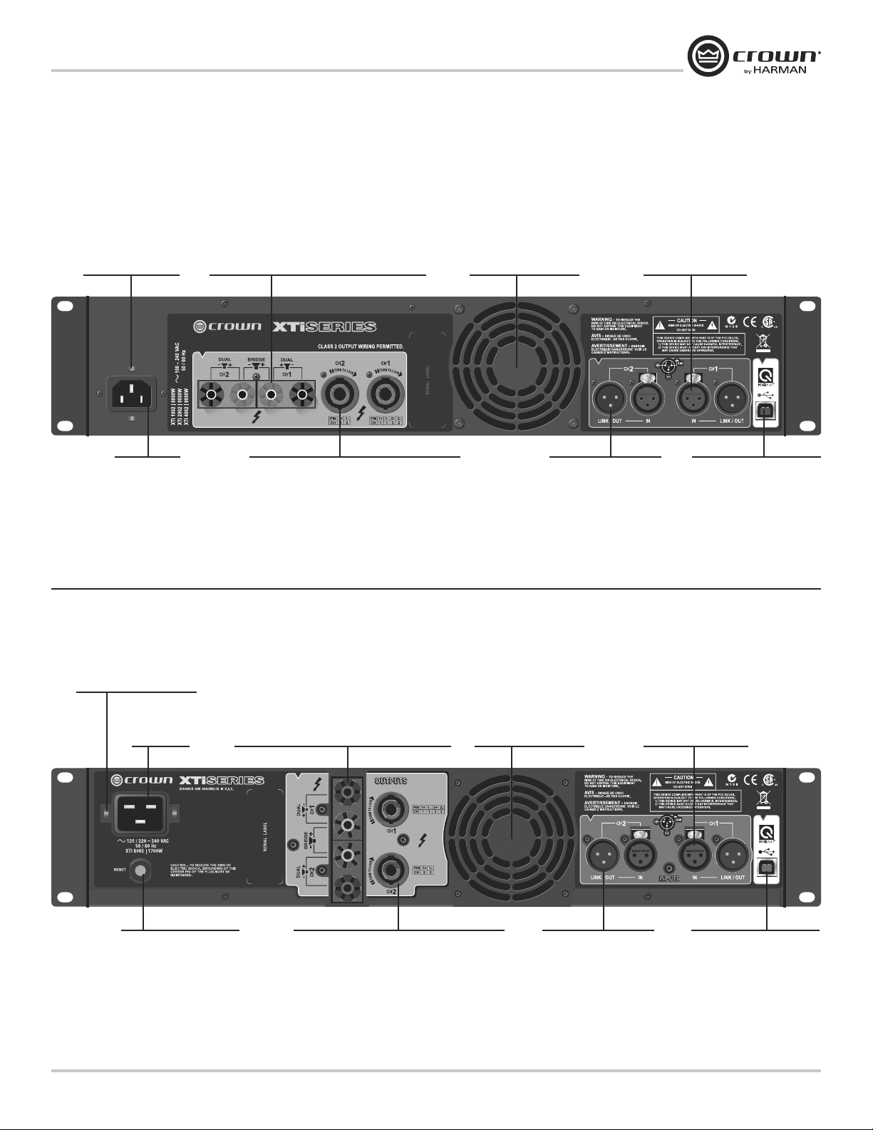
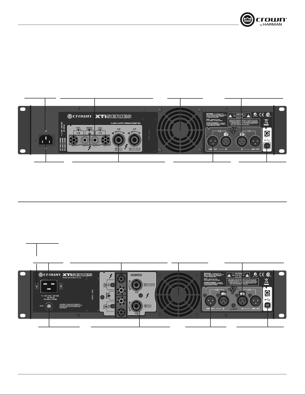
Back Panel Features
XTi 1002, 2002, 4002
Binding Post Output Jacks:
One pair per channel, accepts banana plugs or
Power Cord Clip:
Mounting points for
securing, included
power cord clip.
bare wire. Note: Binding Post outputs on European
models come with safety plugs installed to prevent
European power plugs from being inserted. The
side entry positions for these connectors should
be used with European models.
Fans:
Provide front to back
forced airflow for cooling.
Input Connector:
Two 3-pin XLR input
connectors are provided
(one per channel).
AC Power
Connector
XTi 6002
Power Cord Clip:
Mounting points for securing,
included power cord clip.
AC Power
Connector
4-Pole Speakon® Output Connectors:
These two connectors accept 2-pole and 4-pole
Speakon© connectors. The channel 1 connector is
wired for both channels so it can be used for
bridge-mono wiring or stereo wiring of two
speakers to a single Speakon.
Binding Post Output Jacks:
One pair per channel, accepts banana plugs or
bare wire. Note: Binding Post outputs on European
models come with safety plugs installed to prevent
European power plugs from being inserted. The
side entry positions for these connectors should
be used with European models.
Link/Out Connector:
Two 3-pin XLR output
connectors are provided
(one per channel) to
loop-thru signal from one
amplifier to another.
Fans:
Provide front to back
forced airflow for cooling.
HiQnet USB Connector:
Type B USB connector allows
you to connect the amplifier to
a computer for use with
System Architect
™ software.
Manager
Input Connector:
Two 3-pin XLR input
connectors are provided
(one per channel).
™ and Band
Circuit Breaker:
Provides overload protection
Operation Manual
4-Pole Speakon® Output Connectors:
These two connectors accept 2-pole and 4-pole
Speakon© connectors. The channel 1 connector is
wired for both channels so it can be used for
bridge-mono wiring or stereo wiring of two
speakers to a single Speakon.
Link/Out Connector:
Two 3-pin XLR output
connectors are provided
(one per channel) to
loop-thru signal from one
amplifier to another.
HiQnet USB Connector:
Type B USB connector allows
you to connect the amplifier to
a computer for use with
System Architect
Manager
™ and Band
™ software.
page 9
Page 10
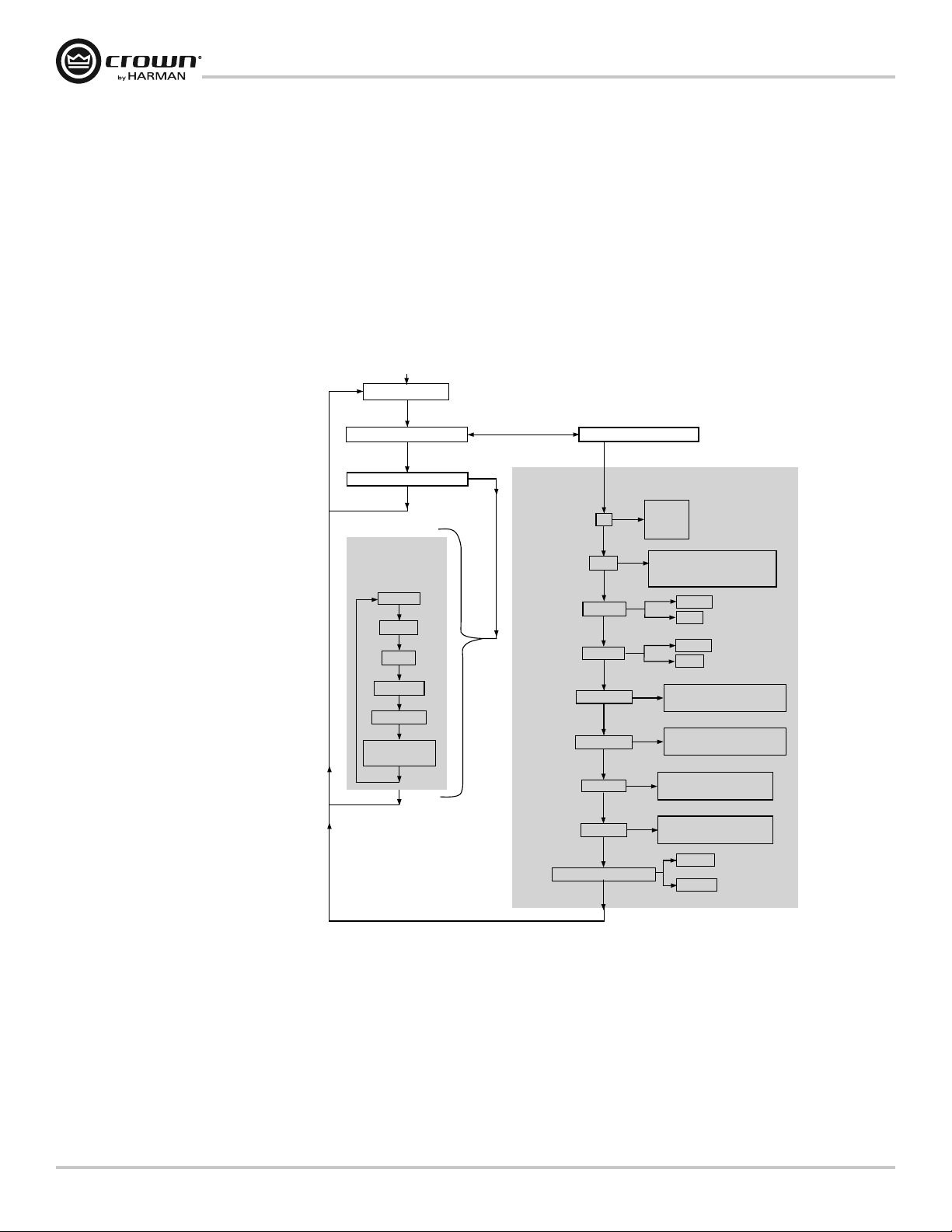
Front Panel Navigation
From the front panel, you can change settings for several of the amplifier’s integrated signal processing features: Input Y,
Crossover Frequency, EQ, Delay, Limiting, and Stereo/Bridge-Mono. The Icons in the display illuminate to show which
features are currently applied and turned on.
When you power-on the amplifier for the first time, the LCD screen displays “DSP OFF” (no DSP is applied). Subsequent
power-ons display the preset that was active when you last shut off the amplifier.
The figure below shows the Menu Tree, which is the navigation path of options in the Menu. It shows how you navigate
through the front panel and which settings are available from the front panel. For full access to all features, it is required that
you hook up the amplifier via USB to a computer and run either HiQnet System Architect™ or Band Manager™ software.
Both are available free via download from the following address: http://hiqnet.harmanpro.com.
XTi2 Series Power Amplifiers
Menu Tree
Power-up
CURRENT PRESET
Sel
FLASHING “PRESET” TEXT
Sel
FLASHING “PRESET” ICON
PRESETS
(TEXT on screen)
Doing nothing returns you to the
CURRENT PRESET after a timeout delay.
Starting from the CURRENT PRESET,
Sel > Sel > Next goes to presets.
Sel > Next > Sel lets you
configure the DSP processes.
Sel
DSP OFF
Next
BRIDGE
Next
XOVER
Next
BRG SUBS
Next
SUB SYNTH
Next
USER PRESETS
6-50
Next
Sel
Next
Next or Prev
DSP PROCESSES
(ICONS on screen)
STEREO/BRIDGE MONO
FLASHING “CONFIG” TEXT
Sel
CH1+CH2
Next
Next
Y
XOV
EQ Ch. 1
EQ Ch. 2
DELAY Ch. 1
DELAY Ch. 2
LIM Ch. 1
LIM Ch. 2
INPUT Y
STEREO
Sel
Next
OFF, 90 Hz, 100 Hz, 1200 Hz,
1500 Hz, 2000 Hz, 2-CH SUB,
Sel
CUSTOM
Next
Prev
Sel
Next
Prev
Sel
Next
CURRENT, OFF, 50, 40, 30,
Sel
Sel
Sel
Sel
Sel
20,10, 9, 8, 7, 6, 5, 4, 3, 2, 1
Next
CURRENT, OFF, 50, 40, 30,
20,10, 9, 8, 7, 6, 5, 4, 3, 2, 1
Next
CURRENT, OFF, –0.5 dB,
–1.0 dB, –1.5 dB... –40 dB
Next
CURRENT, OFF, –0.5 dB,
–1.0 dB, –1.5 dB... –40 dB
Next
Prev
Press Next to see
each processor’s
options, then press
Sel to select an option.
EQ OUT
EQ IN
EQ OUT
EQ IN
BRIDGE
STEREO
page 10
Navigating the LCD Screen Menu: Basics
To step through the Menu options, press the Sel, Next or Prev buttons as described in the menu tree above. Icons
illuminated at the top of the screen show which DSP functions are active with the current preset.
When you are modifying a preset, its icon flashes. You can scroll through its settings with the Prev and Next buttons.
When you see the desired setting, select it by pressing Sel. Doing nothing returns you to the current preset after ten seconds.
In the LCD screen, if the Preset Icon is lit, the current preset is unchanged from its stored settings. If the Custom Icon is lit,
the current preset has been changed from its stored settings.
Operation Manual
Page 11

XTi2 Series Power Amplifiers
Integrated Processing Features
The XTi2 Series amplifiers include a number of integrated processing features which appear as icons on the front panel LCD
screen. They are described below:
NOTE: System Architect Software is required to have full control over all Integrated Processing Features which can be
downloaded from the following URL – http://hiqnet.harmanpro.com/. When controlling more than one XTi2 at a time
you will need USB Hub. We recommend using a Powered USB Hub.
Input Mode
t 4UFSFP *O UIJT NPEF $IBOOFM JOQVU HPFT UP $IBOOFM PVUQVU BOE $IBOOFM JOQVU HPFT UP $IBOOFM PVUQVU 5IJT JT
the mode the amplifier is configured for from the factory.
t 46. $) $) o *O UIJT NPEF UIF $IBOOFM JOQVU TJHOBM BOE $IBOOFM JOQVU TJHOBM BSF TVNNFE BOE GFE UP CPUI
output channels. This provides a 6 dB level boost.
t *OQVU : o *O UIJT NPEF UIF $IBOOFM JOQVU TJHOBM JT TFOU UP UIF $IBOOFM BOE $IBOOFM PVUQVU 5IF DIBOOFM JOQVU
signal is ignored.
Output Mode
t 4UFSFP o *O UIJT NPEF UIF BNQMJmFS TFOET $IBOOFM JOQVU TJHOBM UP UIF $IBOOFM PVUQVU BOE UIF $IBOOFM JOQVU TJHOBM
to the Channel 2 output.
t #SJEHF.POP o *O UIJT NPEF UIF QPXFS PG CPUI BNQMJmFS DIBOOFMT BSF EFMJWFSFE JOUP B TJOHMF PS PIN MPBE
Subharmonic Synth
The Subharmonic Synth feature takes the low frequencies and “synthesizes” or creates new frequencies that are one octave
lower. The two signals are then summed together. Also new, are two user adjustable parametric EQ filters and crossover
frequency filter. These can be used to “shape” the sound and enhance the desired effect.
Equalization
The XTi2 Series provides two blocks of equalization in the signal processing. The input EQ block is before the crossover and
is usually used for the room EQ. The output EQ block is after the crossover and is usually used for speaking tuning.
Input EQ: This input EQ block provides 6 filters per channel each with frequency, gain, and Q that is user controllable.
This block also has a High and Low Shelf Filter per channel which has gain and frequency control.
Output EQ: This output EQ block provides 8 filters per channel each with frequency, gain, and Q control that is user
controllable.
Crossover:
The crossover section provides users with the ability to enable a HighPass and LowPass filter per channel along with
BandPass gain and the ability to change the polarity. This allows the Crossover section to be customized to most system
configurations.
For the HighPass and LowPass Filters, you have the choice of the following filters: Butterworth 6dB/oct, Butterworth 12dB/oct,
Butterworth 18dB/oct, Butterworth 24dB/oct, Butterworth 48dB/oct, Linkwitz-Riley 24dB/oct, and Linkwitz-Riley 48dB/oct.
The BandPass gain provides you with -15dB to +15dB of gain.
Delay
There is up to 50msec of delay available in the signal processing for time aligning your speakers. The software allows you to
enter the amount of delay needed in the form of seconds, feet, or meters and does the calculation for you.
Operation Manual
PeakX Plus Limiter:
Feed-forward output limiter with user-adjustable attack, release and threshold (0.1 dB resolution), plus integrated feedback
limiter to minimize amplifier clipping.
page 11
Page 12

Integrated Processing Features
Advanced Thermal Control
In this section, you can tailor the fan speed to specific applications. You have the choice of the following modes:
t /PSNBM
t &BSMZ
t 'VMM4QFFE
The fan mode can be changed using the front panel buttons at start-up or in the software. The default mode is normal and
should work fine for most applications. Early mode turns the fan on sooner at a “lower” temperature, and Full-speed mode
turns the fan on full-speed full-time. Full-speed mode is not recommended for “dirty” environments.
Advanced Monitoring
This feature allows you to have software visibility of both the Power Supply Temperature and AC Line voltage. AC Line
voltage is “derived” from the amplifier rail voltage and is an approximation of the AC line voltage. This allows you to monitor
the health of your amplifiers and provides for troubleshooting.
Front Panel Lock-Out
To disable or lock the buttons from the front panel, hold the Prev and Next at the same time until the screen says “locked”.
The rotary knobs (attenuators) will still operate. To unlock, hold Prev and Next until the screen says “unlocked”.
The front panel can also be locked out from the software as well from the main panel. However once it is locked in
the software, it can only be unlocked from the software. You cannot unlock from the front panel. The rotary knobs
(attenuators) will still operate.
XTi2 Series Power Amplifiers
page 12
Operation Manual
Page 13

XTi2 Serie Bedienungsanleitung
XTi 1002
XTi 2002
XTi 4002
DEUTSCH
XTi 6002
Weitere Sprachversionen: Um Informationen über die Nutzung dieses Produktes in anderen Sprachen zu erhalten, wenden Sie sich bitte an Ihren örtlichen Crown-
Händler. Wenn Sie Hilfe dabei benötigen, Ihren örtlichen Händler ausfindig zu machen, kontaktieren Sie Crown bitte unter 574-294-8000.
Dieses Handbuch enthält nicht alle Einzelheiten zu Design, Herstellung oder Varianten des Gerätes. Es deckt auch nicht jeden möglichen Fall ab, der während Installation,
Betrieb oder Wartung auftreten könnte.
Die in diesem Handbuch enthaltenen Informationen waren bei Erscheinungsdatum zutreffend. Es können jedoch Aktualisierungen zu diesen Informationen vorliegen. Um die
neueste Version dieses Handbuchs zu erhalten, besuchen Sie bitte die Crown-Webseite auf www.crownaudio.com.
Rechtlicher Hinweis: Crown, Crown Audio und Amcron sind eingetragene Handelsmarken von Crown International. Sonstige Handelsmarken sind das Eigentum ihrer
jeweiligen Eigentümer. Spätere Versionen dieses Handbuchs und zusätzliche Informationen zu diesem Produkt stehen gegebenenfalls auf der Crown-Webseite auf
www.crownaudio.com zur Verfügung.
®
Einige Modelle können unter dem Namen Amcron
©2011 by Harman International, 1718 W. Mishawaka Rd., Elkhart, Indiana 46517-9439 USA, Telefon: 574-294-8000.
exportiert werden.
143060-2 - 4/11
Page 14
Inbetriebnahme
Stereo DSP AUS
Dies ist die Standardwerkseinstellung des Verstärkers.
Der Verstärker ist für den Stereomodus konfiguriert,
wobei sämtliche Verarbeitungsfunktionen deaktiviert sind.
1. Schließen Sie die rechte/linke Signalquelle mit Hilfe
der XLR-Stecker an Kanal 1 und Kanal 2 an
®
2. Schließen Sie mit Hilfe von Speakon
blankem Draht einen Lautsprecher an jeden Kanalausgang an
ACHTUNG: Vor Inbetriebnahme Ihres
Verstärkers lesen und befolgen Sie bitte die
wichtigen Sicherheitsanweisungen, die Sie
zu Beginn dieser Bedienungsanleitung finden.
Werksvoreinstellung Nr. 2: BRÜCKE
Wenn der Verstärker in den BRÜCKEN-Modus (Brücke-Mono) versetzt wird,
wird die Leistung beider Verstärkerkanäle als einzelne 8 oder 4 OhmLast bereitgestellt. Die Verstärker der Serie XTi2 sind werkseitig mit einer
Voreinstellung versehen, die die Konfiguration des Verstärkers für diesen
Betrieb erleichtert.
Bevor Sie beginnen, stellen Sie sicher, dass Sie:
die Signalquelle mit Hilfe von XLR-Steckern an Kanal 1 und Kanal 2
1.
angeschlossen haben (die Verstärkereingänge werden automatisch
summiert, wenn diese Voreinstellung gewählt wird),
den Lautsprecher wie gezeigt angeschlossen haben.
2.
Wenn Sie die Verbindungsklemmenausgänge verwenden, schließen Sie die positive Klemme des Lautsprechers an die
a.
positive Klemme von Kanal 1 und die negative Klemme des Lautsprechers an die positive Klemme von Kanal 2 an
Wenn Sie einen Speakon® Stecker verwenden, schließen Sie die positive Klemme des Lautsprechers an 1+ und
b.
die negative Klemme an 2+ an. Stecken Sie den Stecker nur in den Ausgang von Kanal 1 ein
Folgen Sie diesen einfachen Schritten zur Konfiguration des Verstärkers für den BRÜCKEN-Betrieb:
Drücken Sie die Taste "Set/Enter", so dass "Preset" blinkt
1.
Drücken Sie die Taste "Set/Enter" noch einmal, um die Liste der Voreinstellungen in den Verstärker einzugeben
2.
Drücken Sie "Next/Down" oder “PREV/UP”, bis das Display "Bridge" anzeigt
3.
Drücken Sie "Set/Enter" zur Bestätigung Ihrer Auswahl
4.
Das Display zeigt jetzt "Bridge" an und das Y-Symbol und Brückensymbol sind hervorgehoben
5.
, Bananensteckern oder
Rückwand des XTi 6002.
Die Rückwände des XTi
1002, 2002 und 4002
finden Sie auf Seite 9.
XTi2 Series Power Amplifiers
ANMERKUNG: Individuelle
Verdrahtungen sind nur von
qualifizierten Fachkräften
durchzuführen.
page 14
Operation Manual
Page 15
XTi2 Series Power Amplifiers
Inbetriebnahme
Werksvoreinstellung Nr. 3: XOVER
Im XOVER-Modus wird ein 1,2 kHz Filter der 4. Ordnung (24dB/Oktave)
aktiviert, der Frequenzen von 1,2 kHz und weniger an Kanalausgang 1 und
Frequenzen von 1,2 kHz und mehr an Kanalausgang 2 sendet. Die Verstärker
der Serie XTi2 sind werkseitig mit einer Voreinstellung versehen, die die
Konfiguration des Verstärkers für diesen Betrieb erleichtert.
Bevor Sie beginnen, stellen Sie sicher, dass Sie:
die Signalquelle mit Hilfe eines XLR-Steckers NUR an Kanal 1
1.
angeschlossen haben (die Verstärkereingänge werden automatisch in den
Y-Modus versetzt, wenn diese Voreinstellung gewählt wird),
den Lautsprecher wie gezeigt angeschlossen haben.
2.
Schließen Sie mit Hilfe von Speakon®, Bananensteckern oder blankem Draht den Lautsprecher, der die
a.
niedrigen und mittleren Frequenzen (1,2 kHz und weniger) empfangen soll, an Kanalausgang 1 an
Schließen Sie mit Hilfe von Speakon®, Bananensteckern oder blankem Draht den Lautsprecher,
b.
der die hohen Frequenzen (1,2 kHz und mehr) empfangen soll, an Kanalausgang 2 an
Folgen Sie diesen einfachen Schritten zur Konfiguration des Verstärkers für den XOVER-Betrieb:
Drücken Sie die Taste "Set/Enter", so dass "Preset" blinkt
1.
Drücken Sie die Taste "Set/Enter" noch einmal, um die Liste der Voreinstellungen in den Verstärker einzugeben
2.
Drücken Sie "Next/Down" oder “PREV/UP”, bis das Display "BIAMP" anzeigt
3.
Drücken Sie "Set/Enter" zur Bestätigung Ihrer Auswahl
4.
Das Display zeigt jetzt "BIAMP" an und das Y-Symbol und XOV-Symbol sind hervorgehoben
5.
HIGH 2+/–
LOW 1+/–
Werksvoreinstellung Nr. 4: BRG SUBS
Im Modus BRG SUBS (Bridged Subs - überbrückte Subwoofer) können
Sie den Verstärker für die Verwendung eines einzelnen 8 oder 4 OhmSubwoofer überbrücken. Die Eingänge werden automatisch summiert,
ein 90Hz Tiefpassfilter 4er Ordnung (24 dB/Oktave) wird aktiviert und der
Ausgangsmodus wird in den Bridge-Mono-Modus versetzt. Die Verstärker
der Serie XTi2 sind werkseitig mit einer Voreinstellung versehen, die die
Konfiguration des Verstärkers für diesen Betrieb erleichtert.
Bevor Sie beginnen, stellen Sie sicher, dass Sie:
die Signalquelle mit Hilfe von XLR-Steckern an Kanal 1 und Kanal 2
1.
angeschlossen haben (die Verstärkereingänge werden automatisch
summiert, wenn diese Voreinstellung gewählt wird),
den Lautsprecher wie gezeigt angeschlossen haben.
2.
Wenn Sie die Verbindungsklemmenausgänge verwenden, schließen Sie die positive Klemme des Lautsprechers an
a.
die positive Klemme von Kanal 1 und die negative Klemme des Lautsprechers an die positive Klemme von Kanal 2 an
Wenn Sie einen Speakon® Stecker verwenden, schließen Sie die positive Klemme des Lautsprechers an 1+ und die negative Klemme an 2+ an. Stecken Sie den
b.
Stecker nur in den Ausgang von Kanal 1 ein
Folgen Sie diesen einfachen Schritten zur Konfiguration des Verstärkers für den XOVER-Betrieb:
Drücken Sie die Taste "Set/Enter", so dass "Preset" blinkt
1.
Drücken Sie die Taste "Set/Enter" noch einmal, um die Liste der Voreinstellungen in den Verstärker einzugeben
2.
Drücken Sie "Next/Down" oder “PREV/UP”, bis das Display "XOVER" anzeigt
3.
Drücken Sie "Set/Enter" zur Bestätigung Ihrer Auswahl
4.
Das Display zeigt jetzt "XOVER" an und das Y-Symbol und XOV-Symbol sind hervorgehoben.
5.
Operation Manual
page 15
Page 16

InbetriebnahmeInbetriebnahme
Werksvoreinstellung Nr. 5: SUBSYNTH
Im SUBSYNTH Modus können Sie die SubHarmonic Synth-Funktion
zur Verwendung mit einem Subwoofer auf beiden Kanälen aktivieren.
Die Eingänge werden automatisch summiert, ein 90Hz Tiefpassfilter 4er
Ordnung (24 dB/Oktave) wird sowohl auf Kanal 1 als auch auf Kanal 2
aktiviert und die SubHarmonic Synth-Funktion wird bei einem Pegel
von +12dB aktiviert. Die Verstärker der Serie XTi2 sind werkseitig mit einer
Voreinstellung versehen, die die Konfiguration des Verstärkers für diesen
Betrieb erleichtert.
Bevor Sie beginnen, stellen Sie sicher, dass Sie:
die Signalquelle mit Hilfe von XLR-Steckern an Kanal 1 und Kanal 2
1.
angeschlossen haben (die Verstärkereingänge werden automatisch
summiert, wenn diese Voreinstellung gewählt wird),
den Lautsprecher wie gezeigt angeschlossen haben
2.
Schließen Sie mit Hilfe von Speakon®, Bananensteckern oder blankem Draht einen Lautsprecher an jeden Kanalausgang an
a.
Folgen Sie diesen einfachen Schritten zur Konfiguration des Verstärkers für den SUBSYNTH-Betrieb:
Drücken Sie die Taste "Set/Enter", so dass "Preset" blinkt
1.
Drücken Sie die Taste "Set/Enter" noch einmal, um die Liste der Voreinstellungen in den Verstärker einzugeben
2.
Drücken Sie "Next/Down" oder “PREV/UP”, bis das Display "SUBSYNTH" anzeigt
3.
Drücken Sie "Set/Enter" zur Bestätigung Ihrer Auswahl
4.
Das Display zeigt jetzt "SUBSYNTH" an und das Y-Symbol und XOV-Symbol sind hervorgehoben
5.
XTi2 Series Power Amplifiers
Stellen Sie eine korrekte Kühlung sicher
Bei Verwendung eines Rack montieren Sie die Einheiten direkt übereinander.
Verschließen Sie Freiräume im Rack mit Blindplatten. Blockieren Sie die Belüftungen
an der Vorder- und Rückseite NICHT. Die Seitenwände des Rack müssen einen
Mindestabstand von 5,1 cm (2 Zoll) zu den Seitenwänden des Verstärkers aufweisen
und die Rückseite des Rack muss offen sein.
VORSICHT: Vor der Installation Ihres Verstärkers stellen
Sie sicher, dass er von der Stromquelle getrennt ist, der
Hauptschalter auf "AUS" steht und alle Pegelregler
vollständig zurückgedreht sind (gegen den Uhrzeigersinn).
page 16
Operation Manual
Page 17

XTi2 Series Power Amplifiers
Willkommen
Wenn Sie die Serie XTi2 von Crown wählen, wählen Sie zweifellos einen der leistungsstärksten und innovativsten Verstärker,
der heute auf dem Markt erhältlich ist. Der Grund dafür besteht darin, dass die brandneuen Verstärker der Serie XTi2 nach
wie vor den Standard für unerreichte Leistung und unerreichten Wert definieren und Nacht für Nacht mühelos ihre
Leistung erbringen.
Dank der innovativen Universal Tracking Switch Mode-Stromversorgung und einer voll-integrierten Suite von
Lautsprecherverarbeitungs-Tools liegen diese Verstärker in Punkto thermische Effizienz und Systemflexibilität
an der Spitze ihrer Klasse.
Darüber hinaus profitieren Sie von deutlich optimierten Steuerfunktionen. Peak
Kontrolle über Threshold, Attack und Release. Des Weiteren haben wir den Subharmonic Synth optimiert, so dass Sie
Frequenz, Verstärkung und Filtertyp verwalten und anwendungsspezifische Einstellungen vornehmen können.
Dank der neuen Advanced Thermal-Bedienelemente können Sie jetzt zudem die Lüfterdrehzahl für bestimmte Anwendungen
einstellen und mit den neuen Advanced Monitoring-Bedienelementen können Sie die Temperatur der Stromversorgung
sowie die Netzspannung visuell mittels Software überwachen. Wenn Sie all dies mit den integrierten Rackgriffen aus
Gussaluminium für maximale Haltbarkeit und Tragbarkeit kombinieren, verfügen Sie über die Leistungsfähigkeit,
die Sie - und die Welt - bewegt.
Plus™ Limiters bieten Ihnen vollständige
X
Die Features der nächsten Generation:
t 1FBL9 1MVT -JNJUFST GàS VMUJNBUJWF 1FSGPSNBODF VOE 4DIVU[ EFT 4ZTUFNT EVSDI WPMMTUÊOEJHF ,POUSPMMF àCFS 5ISFTIPME
Attack und Release
t %JF FSXFJUFSUF 4VCIBSNPOJD 4ZOUI4FLUJPO FSNÚHMJDIU EFN #FOVU[FS EJF ,POUSPMMF àCFS ÃCFSHBOHTGSFRVFO[ NBY
Oberschwingungsfrequenz und 1 PEQ-Filter für systemspezifische Einstellungen
t /FVF "EWBODFE 5IFSNBM#FEJFOFMFNFOUF CJFUFO ESFJ CFOVU[FSEFmOJFSUF -àGUFSNPEVTTUFVFSVOHFO OPSNBM WPS[FJUJH VOE
Höchstdrehzahl - zur Anpassung der Lüfterleistung an eine bestimmte Anwendung
t /FVFT "EWBODFE .POJUPSJOH CJFUFU WJTVFMMF ÃCFSXBDIVOH EFS 5FNQFSBUVS EFS 4USPNWFSTPSHVOH NJUUFMT 4PGUXBSF TPXJF
der Netzspannung
t &SIÚIUF "O[BIM EFS 7PSFJOTUFMMVOHFO BVG JOTHFTBNU WPO EFOFO CFOVU[FSEFmOJFSCBS TJOE
t *OUFHSJFSUF (VTTBMVNJOJVNHSJGGF GàS MFJDIUFO 5SBOTQPSU VOE WFSCFTTFSUF )BMUCBSLFJU
t &JOF 4USPNLBCFMSBTUF CJFUFU FJOFO TJDIFSFO "OTDIMVTT EFT 4USPNLBCFMT BO EFO 7FSTUÊSLFS
t "LUVBMJTJFSUF )J2OFU #BOE .BOBHFS VOE 4ZTUFN "SDIJUFDU 4UFVFS4PGUXBSF
Verwendung dieser Bedienungsanleitung
Diese Bedienungsanleitung bietet Ihnen die notwendigen Informationen für die sichere und korrekte Einrichtung und
Inbetriebnahme Ihres Verstärkers. Es werden nicht alle Aspekte der Installation, der Einrichtung oder der Inbetriebnahme,
die unter allen denkbaren Situationen auftreten können, behandelt. Zusätzliche Informationen finden Sie im
Verstärkeranwendungsleitfaden von Crown (Amplifier Application Guide, unter www.crownaudio.com), beim technischen
Support von Crown, bei Ihrem Systeminstallateur oder bei Ihrem Händler.
Wir empfehlen nachdrücklich, alle Anweisungen, Warnungen und Vorsichtsmaßnahmen, die in dieser Bedienungsanleitung
enthalten sind, zu lesen. Bitte senden Sie uns noch heute Ihre Garantieregistrierungskarte für Ihren Schutz. Bewahren Sie Ihren
Kaufvertrag an einem sicheren Ort auf, er ist Ihr offizieller Kaufnachweis.
Operation Manual
page 17
Page 18

XTi2 Series Power Amplifiers
Features der Vorderseite
Anzeigeelemente:
Bereitschaftsanzeige: Zwei grüne LEDs für jeweils einen Kanal leuchten, wenn der Verstärker für die Audiowiedergabe bereit ist.
Signalpräsenzanzeige: Zwei grüne LEDs für jeweils einen Kanal leuchten, wenn die Kanaleingabe -40dBu übersteigt. Diese LEDs sind für
die Überprüfung von Kabeln von Nutzen.
-20 Anzeige: Zwei grüne LEDs für jeweils einen Kanal leuchten, wenn das Ausgangssignal unterhalb der Überlastung -20dB übersteigt.
-10 Anzeige: Zwei grüne LEDs für jeweils einen Kanal leuchten, wenn das Ausgangssignal unterhalb der Überlastung -10dB übersteigt.
Überlastungsanzeige: Zwei rote LEDs jeweils für einen Kanal leuchten am Schwellenwert hörbarer Verzerrung.
Temperaturanzeige: Zwei rote LEDs jeweils für einen Kanal leuchten, wenn aufgrund übermäßiger Temperaturbedingungen thermische
Kompression beginnt.
Kühlentlüftungen:
Zwangsluftströmung
von der Vorderseite
zur Rückseite.
ACHTUNG: Schließen Sie den Ausgang niemals an
eine Stromversorgung, an eine Batterie oder an das
Stromnetz an. Es besteht die Gefahr von Stromschlägen.
Verstärkungsregler
(Pegelregler):
Zwei schwarze
Pegeldrehregler für
jeweils einen Kanal.
Sel/Prev/Next Tasten:
Drei Tasten unterhalb des
LCD-Bildschirms für den
Zugri auf Menüelemente
und zur Sperrung der
Vorderseite.
LCD-Bildschirm:
Ein hintergrundbeleuchteter
LCD-Bildschirm zeigt aktivierte
Voreinstellungen und die
Lautsprecherbearbeitung an.
Hauptschalter und
Anzeige:
Zum Ein- und Ausschalten
des Verstärkers. Die blaue
LED leuchtet, wenn der
Strom eingeschaltet ist.
page 18
Operation Manual
Page 19
XTi2 Series Power Amplifiers
e
Features der Rückseite
XTi 1002, 2002, 4002
Hauptschalter und Anzeige:
Ein Paar pro Kanal für Bananenstecker oder blanken Draht.
Netzkabel-Clip:
Haltepunkte zur
Befestigung,
Netzkabel-Clip
inbegriffen.
Anmerkung: Die Verbindungsklemmenausgänge an
europäischen Modellen sind mit Sicherheitssteckern
ausgerüstet, damit keine europäischen Netzstecker eingesteckt
werden können. Bei europäischen Modellen sind für diese
Stecker die Seiteneingangspositionen zu
verwenden.können.eingangspositionen zu verwenden.
Lüfter:
Sorgen für eine
Zwangsluftströmung
von der Vorderseite
zur Rückseite.
Eingangsklemmen:
Zwei 3-Pin XLR Eingangsklemmen
sind bereitgestellt (eine pro Kanal).
Netzanschluss
XTi 6002
Netzkabel-Clip:
Haltepunkte zur
Befestigung,
Netzkabel-Clip
inbegriffen.
Netzanschluss
4-polige Speakon® Ausgangsbuchsen:
Diese beiden Buchsen sind für 2-polige und 4-polige Speakon©
Stecker geeignet. Die Buchse für Kanal 1 ist für beide Kanäle
verdrahtet, so dass sie für überbrückte Mono-Verdrahtung oder
Stereo-Verdrahtung von zwei Lautsprechern zu einem
einzelnen Speakon verwendet werden kann.
Anschlüsse der Verbindungsklemmenausgänge:
Anschlüsse der Verbindungsklemmenausgänge:
Ein Paar pro Kanal für Bananenstecker oder blanken Draht.
Anmerkung: Die Verbindungsklemmenausgänge an
europäischen Modellen sind mit Sicherheitssteckern
ausgerüstet, damit keine europäischen Netzstecker
eingesteckt werden können. Bei europäischen Modellen
sind für diese Stecker die Seiteneingangspositionen
zu verwenden.
Link/Out Anschluss:
Zwei 3-Pin XLR Eingangsklemmen
sind bereitgestellt (eine pro Kanal),
um das Signal von einem Verstärker
zu einem anderen in einer Schleife
durchzuführen.
Lüfter:
Sorgen für eine
Zwangsluftströmung
von der Vorderseite
zur Rückseite.
HiQnet USB Anschluss:
USB-Anschlüsse vom Typ B
ermöglichen den Anschluss
des Verstärkers an einen
Computer mit der Software
System Architect™ und
Band Manager™.
Eingangsklemmen:
Zwei 3-Pin XLR Eingangsklemmen
sind bereitgestellt (eine pro Kanal).
Schutzschalter:
Für Überlastungsschutz.
Operation Manual
4-polige Speakon® Ausgangsbuchsen:
Diese beiden Buchsen sind für 2-polige und
4-polige Speakon© Stecker geeignet. Die Buchse
für Kanal 1 ist für beide Kanäle verdrahtet, so dass
sie für überbrückte Mono-Verdrahtung oder
Stereo-Verdrahtung von zwei Lautsprechern zu
einem einzelnen Speakon verwendet werden kann.
Link/Out Anschluss:
Zwei 3-Pin XLR
Eingangsklemmen sind
bereitgestellt (eine pro
Kanal), um das Signal
von einem Verstärker zu
einem anderen in einer
Schleife durchzuführen.
HiQnet USB Anschluss:
USB-Anschlüsse vom Typ B
ermöglichen den Anschluss
des Verstärkers an einen
Computer mit der Software
System Architect™ und
Band Manager™.
page 19
Page 20

Navigation auf der Vorderseite
Auf der Vorderseite können die Sie Einstellungen für mehrere integrierte Signalverarbeitungsfunktionen ändern:
&JOHBCF : ÃCFSHBOHTGSFRVFO[ &2 %FMBZ #FHSFO[VOH VOE 4UFSFP#SàDLF.POP %JF 4ZNCPMF BVG EFN %JTQMBZ MFVDIUFO
um anzuzeigen, welche Funktionen gegenwärtig angewendet werden und aktiviert sind.
Wenn Sie den Verstärker erstmalig einschalten, zeigt der LCD-Bildschirm "DSP OFF" an (es wird kein DSP angewendet).
Bei nachfolgendem Einschalten wird die Voreinstellung angezeigt, die zu dem Zeitpunkt aktiv war als Sie den Verstärker
zuletzt ausgeschaltet haben.
Die Abbildung unten zeigt den Menübaum, der den Navigationspfad der Optionen im Menü darstellt. Er zeigt, wie Sie auf
der Vorderseite des Verstärkers navigieren können und welche Einstellungen auf der Vorderseite verfügbar sind. Für einen
vollständigen Zugriff auf alle Funktionen schließen Sie den Verstärker über USB an einen Computer an und führen Sie
entweder die Software HiQnet System Architect™ oder Band Manager™ aus. Beide Softwareanwendungen können kostenlos
von folgender Website heruntergeladen werden: http://hiqnet.harmanpro.com.
XTi2 Series Power Amplifiers
Menübaum
Power-up
AKTUELLE VOREINSTELLUNG
Sel (auswählen)
BLINKENDER "PRESET" TEXT
Sel
BLINKENDES "PRESET" SYMBOL
dem Bildschirm)
Wenn Sie keine Eingabe vornehmen,
kehrt die Anzeige nach einer
Zeitverzögerung zur
AKTUELLEN VOREINSTELLUNG zurück.
Beginnend bei der AKTUELLEN
VOREINSTELLUNG bei Einschalten
des Geräts, gelangen Sie mit
Sel > Sel > Next zu den Voreinstellungen.
Drücken Sie "Sel > Next > Sel",
um die DSP-Prozesse zu konfigurieren.
Sel
PRESETS
(TEXT auf
DSP OFF
Next
BRÜCKE
Next
XOVER
Next
BRG SUBS
Next
SUB SYNTH
Next
USER PRESETS
6-50
Next
Sel
Next (Weiter) or Prev
Next
DSP PROZESSE
(SYMBOLE auf
dem Bildschirm)
EQ Kanal 1
EQ Kanal 2
DELAY Kanal 1
DELAY Kanal 2
LIM Kanal 1
LIM Kanal 2
STEREO/BRÜCKE MONO
BLINKENDER TEXT "CONFIG"
Sel
Kanal 1 +
Kanal 2
Next
Next
EINGANG Y
Y
STEREO
Sel
Next
XOV
AUS, 90 Hz, 100 Hz, 1200 Hz,
1500 Hz, 2000 Hz, 2-Kanal SUB,
Sel
INDIVIDUELL
Next
EQ OUT
EQ IN
Prev
Sel
Next
EQ OUT
EQ IN
Prev
Sel
Next
AKTUELL, AUS, 50, 40, 30,
Sel
Sel
Sel
Sel
Sel
20,10, 9, 8, 7, 6, 5, 4, 3, 2, 1
Next
AKTUELL, AUS, 50, 40, 30,
20,10, 9, 8, 7, 6, 5, 4, 3, 2, 1
Next
AKTUELL, AUS, –0,5 dB,
–1,0 dB, –1,5 dB... –40 dB
Next
AKTUELL, AUS, –0,5 dB,
–1,0 dB, –1,5 dB... –40 dB
Next
BRÜCKE
STEREO
Prev (Zurück)
Drücken Sie "Next",
um die Optionen der
einzelnen Prozessoren
anzuzeigen, und drücken
Sie "Sel", um eine Option
auszuwählen.
page 20
Navigation durch das Menü des LCD-Bildschirms: Grundlagen
Drücken Sie Sel, Next oder Prev wie oben im Menübaum beschrieben, um die Menüoptionen zu durchlaufen.
Symbole, die oben am Bildschirm leuchten, zeigen an, welche DSP-Funktionen bei der aktuellen Voreinstellung aktiv sind.
Wenn Sie eine Voreinstellung modifizieren, blinkt deren Symbol. Sie können durch Drücken auf Prev und Next durch
die Einstellungen scrollen. Wenn Sie die gewünschte Einstellung sehen, wählen Sie sie durch Drücken auf "Sel" aus.
Wenn Sie keine Eingabe vornehmen, kehrt die Anzeige nach zehn Sekunden zur aktuellen Voreinstellung zurück.
Wenn das Voreinstellungssymbol auf dem LCD-Bildschirm leuchtet, bleibt die aktuelle Voreinstellung unverändert.
Wenn das Symbol "Benutzerdefininiert" (Custom) leuchtet, wurde die aktuelle Voreinstellung im Vergleich zu den
gespeicherten Einstellungen geändert.
Operation Manual
Page 21

XTi2 Series Power Amplifiers
Integrierte Verarbeitungsfunktionen
Die Verstärker der Serie XTi2 weisen eine Anzahl von integrierten Verarbeitungsfunktionen auf, die als Symbole auf
dem LCD-Bildschirm auf der Vorderseite erscheinen. Diese werden weiter unten beschrieben:
ANMERKUNG: Die Software "System Architect" ist für eine vollständige Kontrolle über alle integrierten
Verarbeitungsfunktionen erforderlich. Diese Software kann von folgender Website heruntergeladen werden:
http://hiqnet.harmanpro.com/. Wenn Sie mehr als einen XTi2 gleichzeitig steuern, benötigen Sie einen USB-Hub.
Wir empfehlen einen gespeisten USB-Hub.
Eingangsmodus
t 4UFSFP *O EJFTFN .PEVT JTU EFS &JOHBOH WPO ,BOBM NJU EFN "VTHBOH WPO ,BOBM WFSCVOEFO VOE EFS &JOHBOH
von Kanal 2 ist mit dem Ausgang von Kanal 2 verbunden. Dies ist die Werkskonfiguration des Verstärkers.
t 46. $) $) o *O EJFTFN .PEVT XFSEFO EJF &JOHBOHTTJHOBMF WPO ,BOBM VOE ,BOBM TVNNJFSU
und an beide Ausgangskanäle ausgegeben. Dadurch wird eine Verstärkung von 6 dB erreicht.
t *OQVU : o *O EJFTFN .PEVT XJSE EBT &JOHBOHTTJHOBM WPO ,BOBM BO EFO "VTHBOH WPO ,BOBM VOE ,BOBM HFTFOEFU
Das Eingangssignal von Kanal 2 wird ignoriert.
Ausgangsmodus
t 4UFSFP o *O EJFTFN .PEVT TFOEFU EFS 7FSTUÊSLFS EBT &JOHBOHTTJHOBM WPO ,BOBM BO EFO "VTHBOH WPO ,BOBM VOE EBT
Eingangssignal von Kanal 2 an den Ausgang von Kanal 2
t #SJEHF.POP o *O EJFTFN .PEVT XJSE EJF -FJTUVOH CFJEFS 7FSTUÊSLFSLBOÊMF BO FJOF FJO[FMOF PEFS 0IN-BTU BOHFMFHU
Subharmonic Synth
Die Subharmonic Synth-Funktion nimmt die niedrigen Frequenzen und "synthetisiert" bzw. erzeugt neue Frequenzen,
die eine Oktave niedriger sind. Daraufhin werden beide Signale summiert. Ebenfalls neu sind zwei benutzereinstellbare
QBSBNFUSJTDIF &2'JMUFS VOE ÃCFSHBOHTGSFRVFO[mMUFS %JFTF LÚOOFO [VS 'PSNVOH EFT ,MBOHT VOE [VS 0QUJNJFSVOH EFT
gewünschten Effekts verwendet werden.
Equalizing
%JF 4FSJF 95J CJFUFU [XFJ &RVBMJ[JOH#MÚDLF JO EFS 4JHOBMWFSBSCFJUVOH %FS &JOHBOHT&2#MPDL MJFHU WPS EFN ÃCFSHBOH XJSE
OPSNBMFSXFJTF GàS EFO 3BVN&2 WFSXFOEFU %FS "VTHBOHT&2#MPDL MJFHU IJOUFS EFN ÃCFSHBOH XJSE OPSNBMFSXFJTF GàS EJF
Sprecheinstellung verwendet.
Eingangs-EQ:Dieser Eingangs-EQ-Block bietet 6 Filter pro Kanal, von denen jeder Frequenz, Gain und Q aufweist, die der
Benutzer regeln kann. Dieser Block verfügt darüber hinaus über einen Hoch- und Tief-Shelf-Filter pro Kanal, der Gain- und
Frequenzregelung aufweist.
Ausgangs-EQ:Dieser Ausgangs-EQ-Block bietet 8 Filter pro Kanal, von denen jeder Frequenz-, Gain- und Q-Regelung
aufweist, die der Benutzer regeln kann.
Übergang:
.JU EFS ÃCFSHBOHTTFLUJPO LÚOOFO EJF #FOVU[FS FJOFO )PDIQBTTmMUFS VOE FJOFO 5JFGQBTTmMUFS QSP ,BOBM [VTBNNFO
NJU #BOEQBTT(BJO BLUJWJFSFO VOE EJF 1PMBSJUÊU ÊOEFSO %BEVSDI LBOO EJF ÃCFSHBOHTTFLUJPO BO EJF NFJTUFO
Systemkonfigurationen angepasst werden.
Als Hoch- und Tiefpassfilter können folgende Filter gewählt werden: Butterworth 6dB/Okt, Butterworth 12dB/Okt, Butterworth
18dB/Okt, Butterworth 24dB/Okt, Butterworth 48dB/Okt, Linkwitz-Riley 24dB/Okt, und Linkwitz-Riley 48dB/Okt.
Das Bandpass-Gain bietet eine Verstärkung von -15dB bis +15dB.
Operation Manual
Delay
Es ist ein Delay von 50 msek in der Signalverarbeitung verfügbar, damit Sie Ihre Lautsprecher synchron ausrichten können.
Die Software ermöglicht Ihnen, die benötigte Delay-Größe in Sekunden, Metern oder Fuß einzugeben, und übernimmt
die Berechnung.
page 21
Page 22

Integrierte Verarbeitungsfunktionen
PeakX Plus Limiter:
Ein Feed-Forward-Ausgangsbegrenzer mit benutzereinstellbarem Attack, Release und Threshold (Auflösung 0,1 dB),
plus integriertem Feedback-Begrenzer zur Einschränkung von Verstärkerüberlastungen.
Advanced Thermal Control
In dieser Sektion können Sie die Lüfterdrehzahl für bestimmte Anwendungen anpassen. Folgende Modi stehen zur Wahl:
t /PSNBM
t 7PS[FJUJH
t )ÚDITUESFI[BIM
Der Lüftermodus kann mit Hilfe der Tasten auf der Vorderseite beim Start oder mit Hilfe der Software geändert werden.
Der Standardmodus ist "normal" und ist für die meisten Anwendungen geeignet. Im Modus "Vorzeitig" wird der Lüfter früher
bei einer "niedrigeren" Temperatur eingeschaltet. Im Modus "Höchstdrehzahl" läuft der Lüfter stets mit Höchstdrehzahl.
Der Modus Höchstdrehzahl wird in "kontaminierten" Umgebungen nicht empfohlen.
Advanced Monitoring
%JFTF 'VOLUJPO CJFUFU FJOF WJTVFMMF ÃCFSXBDIVOH EFS 5FNQFSBUVS EFS 4USPNWFSTPSHVOH TPXJF EFS /FU[TQBOOVOH NJUUFMT
Software. Die Netzspannung wird von der Schienenspannung des Verstärkers "abgeleitet" und ist eine Annäherung an die
Netzspannung. Diese Funktion ermöglicht Ihnen, den Zustand Ihrer Verstärker zu überwachen und hilft bei der Fehlersuche.
XTi2 Series Power Amplifiers
Sperre der Tasten der Vorderseite
Zum Deaktivieren oder Sperren der Tasten der Vorderseite halten Sie "Prev" und "Next" gleichzeitig gedrückt, bis auf dem
Bildschirm "locked" (gesperrt) erscheint. Die Drehknöpfe (Lautstärkeregler) sind nach wie vor aktiv. Zum Entsperren halten
Sie "Prev" und "Next" gedrückt, bis auf dem Bildschirm "unlocked" (entsperrt) erscheint.
Die Tasten der Vorderseite können ebenfalls mit Hilfe der Software sowie über die Hauptkonsole gesperrt werden. Nachdem
die Vorderseite jedoch in der Software gesperrt wurde, kann diese nur mit der Software wieder entsperrt werden. Sie können
die Entsperrung nicht auf der Vorderseite vornehmen. Die Drehknöpfe (Lautstärkeregler) sind nach wie vor aktiv.
page 22
Operation Manual
Page 23
Serie XTi2 Manual de Operación
XTi 1002
XTi 2002
XTi 4002
ESPAÑOL
XTi 6002
Obtención de Versiones en otro Idioma: para obtener información en otro idioma sobre el uso de este producto, por favor póngase en contacto con su Distribuidor
local de Crown. Si necesita ayuda para ubicar a un distribuidor local, por favor póngase en contacto con Crown al 574-294-8000.
Este manual no incluye todos los detalles del diseño, fabricación o variaciones del equipo. Así como tampoco incluye todas las posibles situaciones que pueden surgir en el
momento de la instalación, operación o mantenimiento.
Este manual posee información que en el momento de la publicación se consideró certera. No obstante, esta información puede haberse actualizado. Para conseguir la
última versión de este manual, por favor visite la página Web de Crown www.crownaudio.com.
Aviso de Marca Registrada: Crown, Crown Audio y Amcron son marcas registradas de Crown International. Las otras marcas son propiedad de sus respectivos dueños.
Las versiones posteriores de este manual e información adicional sobre este producto pueden estar disponibles en la página Web de Crown www.crownaudio.com.
Algunos modelos pueden ser exportados bajo el nombre Amcron
©2011 por Harman International, 1718 W. Mishawaka Rd., Elkhart, Indiana 46517-9439 EE.UU. Teléfono: 574-294-8000.
®
143060-2 - 4/11
Page 24

Cómo empezar
Stereo DSP Off
(procesamiento digital de señal estéreo desactivado)
El amplificador sale de fábrica en este modo por defecto.
El amplificador está configurado para el modo estéreo con
todos los procesamientos desactivados.
1. Conecte la fuente de señal Left/Right (izquierda/derecha) al
canal 1 (CH1) y al canal 2 (CH2) usando los conectores XLR
®
2. Conecte un altavoz a cada salida de canal usando Speakon
conectores banana o cable pelado
ADVERTENCIA: Antes de empezar a
configurar su amplificador, asegúrese de
leer y seguir las instrucciones de seguridad
importantes que aparecen al principio del
presente manual.
Preajuste de fábrica núm. 2: BRIDGE (PUENTE)
Al poner el amplificador en modo BRIDGE (bridge-mono), entrega la potencia
de los dos canales del amplificador en una única carga de 8 o 4 ohmios. Los
amplificadores de la serie XTi2 se entregan ya cargados con un ajuste previo
que facilita la configuración del amplificador para esta función.
Antes de empezar, debe asegurarse de:
Conectar la fuente de señal al canal 1 y al canal 2 usando los conectores
1.
XLR (las entradas del amplificador se sumarán de forma automática al
seleccionar esta configuración)
Conectar el altavoz como se muestra.
2.
Si usa un borne, conecte el terminal positivo del altavoz al terminal positivo
a.
del canal 1 y el terminal negativo del altavoz al terminal positivo del canal 2
Si usa un conector Speakon®, conecte el terminal positivo del altavoz a 1+ y el terminal negativo a 2+.
b.
Conecte el conector a la salida del canal 1 únicamente.
Siga estos pasos rápidos para configurar el amplificador en modo PUENTE:
Pulse el botón “Set/Enter” (Establecer/Introducir) y verá que parpadea la palabra “Preset” (Preajuste)
1.
Vuelva a pulsar el botón “Set/Enter” para introducir la lista de configuraciones en el amplificador
2.
Pulse el botón “Next/Down” (Siguiente/Bajar) o “PREV/UP” (Anterior/Subir) hasta que aparezca en la pantalla “Bridge”
3.
Pulse el botón “Set/Enter” para confirmar su selección
4.
En la pantalla podrá verse ahora “Bridge” con el icono Y y el icono Bridge destacados
5.
,
Vista de la parte posterior del XTi 6002.
En la página 9, aparece la parte posterior
de los modelos XTi 1002, 2002 y 4002.
XTi2 Series Power Amplifiers
NOTA: Los cableados
personalizados debe realizarlos
personal cualificado.
page 24
Operation Manual
Page 25

XTi2 Series Power Amplifiers
Cómo empezar
Preajuste de fábrica núm. 3: XOVER
(DIVISOR DE FRECUENCIA)
Al poner el amplificador en modo XOVER, se activa un filtro de 4º orden (24 dB/
octava) de 1,2 kHz que envía frecuencias de 1,2 kHz e inferiores a la salida del
canal 1 y frecuencias de 1,2 kHz y superiores a la salida del canal 2.
Los amplificadores de la serie XTi2 se entregan ya cargados con un ajuste
previo que facilita la configuración del amplificador para esta función.
Antes de empezar, debe asegurarse de:
Conectar la fuente de señal al canal 1 usando SÓLO un conector XLR
1.
(las entradas del amplificador se pondrán en modo Y al seleccionar esta configuración)
Conectar el altavoz como se muestra.
2.
Conecte el altavoz en el que desea recibir las frecuencias bajas y medias (1,2 kHz e inferiores)
a.
a la salida del canal 1 usando Speakon
Conecte el altavoz en el que desea recibir las frecuencias altas (1,2 kHz y superiores) a la salida del canal 2 usando Speakon®, conectores banana o cable pelado
b.
Siga estos pasos rápidos para configurar el amplificador en modo de funcionamiento XOVER:
Pulse el botón “Set/Enter” y verá que parpadea la palabra “Preset”
1.
Vuelva a pulsar el botón “Set/Enter” para introducir la lista de configuraciones en el amplificador
2.
Pulse el botón “Next/Down” o “PREV/UP” hasta que aparezca en la pantalla “BIAMP”
3.
Pulse el botón “Set/Enter” para confirmar su selección
4.
En la pantalla podrá verse ahora “BIAMP” con el icono Y y el icono XOV destacados
5.
®
, conectores banana o cable pelado
HIGH 2+/–
LOW 1+/–
Preajuste de fábrica núm. 4: BRG SUBS
(SUB-BAJOS PUENTEADOS)
Al poner el amplificador en modo BRG SUBS (sub-bajos puenteados),
puede puentear al amplificador para usarlo con un único sub-bajo de 8 o
4 ohmios. Las entradas se suman de forma automática, se activa un filtro
paso-bajo de 4º orden (24 db/octava) de 90 Hz y el modo de salida se pone
en modo puente-mono. Los amplificadores de la serie XTi2 se entregan ya
cargados con un ajuste previo que facilita la configuración del amplificador
para esta función.
Antes de empezar, debe asegurarse de:
Conectar la fuente de señal al canal 1 y al canal 2 usando los conectores
1.
XLR (las entradas del amplificador se sumarán de forma automática al
seleccionar esta configuración)
Conectar el altavoz como se muestra.
2.
Si usa un borne, conecte el terminal positivo del altavoz al terminal positivo del canal 1 y el terminal negativo del altavoz al terminal positivo del canal 2
a.
Si usa un conector Speakon®, conecte el terminal positivo del altavoz a 1+ y el terminal negativo a 2+. Conecte el conector a la salida del canal 1 únicamente.
b.
Siga estos pasos rápidos para configurar el amplificador en modo de funcionamiento XOVER (divisor de frecuencia):
Pulse el botón “Set/Enter” y verá que parpadea la palabra “Preset”
1.
Vuelva a pulsar el botón “Set/Enter” para introducir la lista de configuraciones en el amplificador
2.
Pulse el botón “Next/Down” o “PREV/UP” hasta que aparezca en la pantalla “XOVER”
3.
Pulse el botón “Set/Enter” para confirmar su selección
4.
En la pantalla podrá verse ahora “XOVER” con el icono Y y el icono XOV destacados
5.
Operation Manual
page 25
Page 26
Cómo empezarCómo empezar
Preajuste de fábrica núm. 5: SUBSYNTH
(Sintetizador subarmónico)
Al poner el amplificador en modo SUBSYNTH, nos permite activar la función
de sintetizador subarmónico para usarla con un sub-bajo en ambos canales.
Las entradas se suman de forma automática, se activa un filtro de 4º orden (24
dB/octava) de 90 Hz en el canal 1 y en el canal 2, y la función de sintetizador
subarmónico se activa a un nivel de +12 dB. Los amplificadores de la serie
XTi2 se entregan ya cargados con un ajuste previo que facilita la configuración
del amplificador para esta función.
Antes de empezar, debe asegurarse de:
Conectar la fuente de señal al canal 1 y al canal 2 usando los conectores
1.
XLR (las entradas del amplificador se sumarán de forma automática al
seleccionar esta configuración)
Conectar el altavoz como se muestra
2.
Conecte un altavoz a cada salida de canal usando Speakon®, conectores banana o cable pelado
a.
Siga estos pasos rápidos para configurar el amplificador en modo SINTETIZADOR SUBARMÓNICO:
Pulse el botón “Set/Enter” y verá que parpadea la palabra “Preset”
1.
Vuelva a pulsar el botón “Set/Enter” para introducir la lista de configuraciones en el amplificador
2.
Pulse el botón “Next/Down” o “PREV/UP” hasta que aparezca en la pantalla “SUBSYNTH”
3.
Pulse el botón “Set/Enter” para confirmar su selección
4.
En la pantalla podrá verse ahora “SUBSYNTH” con el icono Y y el icono XOV destacados
5.
XTi2 Series Power Amplifiers
Compruebe que existe una ventilación correcta
Cuando use un bastidor, coloque las unidades directamente una encima de otra.
Cierre cualquier espacio abierto del bastidor con paneles metálicos. NO bloquee las
ventilaciones frontales ni las posteriores. Las paredes laterales del bastidor deberán
estar a un mínimo de 5,1 cm de distancia de los laterales del amplificador, y la parte
posterior del bastidor debe estar abierta.
AVISO: Antes de empezar con la instalación de su amplificador,
asegúrese de que está desconectado de la red de alimentación,
que el botón de conexión está en la posición "off" y que todos los
controles de nivel están al mínimo (en el sentido contrario a las
agujas del reloj).
page 26
Operation Manual
Page 27

XTi2 Series Power Amplifiers
Bienvenido
No hay duda, cuando elige la serie XTi2 de Crown, está eligiendo uno de los amplificadores más potentes e innovadores del
mercado actual. Está claro que los nuevos amplificadores de la serie XTi2 siguen siendo el ejemplo a seguir gracias a un
funcionamiento y un valor inigualables, además de dejar patente su valor noche tras noche sin ningún esfuerzo.
Con innovaciones tales como una alimentación de modo conmutado de seguimiento universal y un conjunto de herramientas
de procesamiento de altavoces totalmente integradas, estos amplificadores son los mejores de su clase en relación con la
eficiencia térmica y la flexibilidad del sistema.Además, ofrecen unas capacidades de control realmente mejoradas. La adición
de limitadores Peak
el sintetizador subarmónico para que usted pueda gestionar con facilidad la frecuencia, ganancia y tipo de filtro, lo que
permite una sintonización específica según la aplicación.
Asimismo, ahora podrá personalizar la velocidad del ventilador para aplicaciones concretas con los nuevos controles térmicos
avanzados y tendrá visibilidad del software de la temperatura de la fuente de alimentación y el voltaje de línea de CA con los
nuevos controles de seguimiento avanzado. Combine todo esto con unas asas de bastidor de aluminio integradas para una
durabilidad y portabilidad máximas y podrá moverse sin problemas... y hacer que tiemble el mundo.
Plus™ le ofrece un control total sobre el umbral, ataque y lanzamiento, además de que hemos mejorado
X
Las funciones de nueva generación son:
t -JNJUBEPSFT 1FBL9 1MVT RVF PGSFDFO MP ÞMUJNP FO QSPUFDDJØO Z SFOEJNJFOUP EFM TJTUFNB BM QFSNJUJSVO DPOUSPM UPUBM TPCSF
el umbral, ataque y lanzamiento
t 6OB TFDDJØO EF TJOUFUJ[BEPS TVCBSNØOJDP NFKPSBEB RVF PGSFDF BM VTVBSJP DPOUSPM TPCSF FM EJWJTPS EF GSFDVFODJBT
frecuencia armónica máxima y un filtro PEQ para una sintonización específica del sistema
t /VFWPT DPOUSPMFT UÏSNJDPT BWBO[BEPT RVF QFSNJUFO DPOUSPMFT EF NPEP EF WFOUJMBEPS EFGJOJEPT QPS FM VTVBSJP
velocidad normal, temprana y máxima para ajustar el funcionamiento del ventilador a una aplicación específica
t /VFWP DPOUSPM BWBO[BEP RVF PGSFDF WJTJCJMJEBE EFM TPGUXBSF EF MB UFNQFSBUVSB EF MB GVFOUF EF BMJNFOUBDJØO Z FM WPMUBKF
de la línea de CC
t .BZPS DBOUJEBE EF DPOGJHVSBDJPOFT IBTUB VO UPUBM EF EF MBT DVBMFT QVFEFO TFS EFGJOJEBT QPS FM VTVBSJP
t "TBT EF BMVNJOJP JOUFHSBEBT QBSB VO USBOTQPSUF DØNPEP Z VOB NBZPS EVSBCJMJEBE
t $MJQ EF CMPRVFP EFM DBCMF EF BMJNFOUBDJØO RVF PGSFDF VOB DPOFYJØO TFHVSB FOUSF FM BNQMJGJDBEPS Z FM DBCMF EF BMJNFOUBDJØO
t 4PGUXBSF EF DPOUSPM )J2OFU #BOE .BOBHFS Z 4ZTUFN "SDIJUFDU BDUVBMJ[BEP
Cómo usar el presente manual
El presente manual le ofrece la información necesaria para configurar y utilizar de forma segura y correcta su amplificador.
No cubre la totalidad de los aspectos de la instalación, configuración y funcionamiento que pueden aparecer en cualquier
condición. Para más información, consulte la Guía de aplicación del amplificador de Crown (disponible en w ww.crownaudio.com)
o el soporte técnico de Crown, o póngase en contacto con el instalador de su sistema o su distribuidor.
Recomendamos encarecidamente que lea todas las instrucciones, advertencias y avisos contenidos en el presente manual.
Asimismo, para su protección, envíe la tarjeta de registro de la garantía hoy mismo. Y guarde la factura de la compra, ya que
es su prueba de compra oficial.
Operation Manual
page 27
Page 28

Funciones del panel frontal
XTi2 Series Power Amplifiers
page 28
ADVERTENCIA: Nunca conecte la salida a una fuente de
energía eléctrica, batería o conductor de fuerza.
Puede sufrir una descarga eléctrica.
Operation Manual
Page 29

XTi2 Series Power Amplifiers
Funciones del panel posterior
XTi 1002, 2002, 4002
Clip para el cable
de alimentación:
Puntos de anclaje para
asegurar, incluido el clip
para el cable de
alimentación
Conector de
alimentación
de CA
Conectores hembra de salida:
Un par por canal, aceptan conectores banana o cable
pelado. Nota: Los conectores hembra de salida de los
modelos europeos se entregan con tapones de
seguridad instalados para evitar que se inserten
enchufes europeos. Con los modelos europeos, deben
usarse las entradas laterales para estos conectores.
Conectores de salida Speakon®
de 4 polos:
Estos dos conectores aceptan conectores
®
Speakon
está conectado para ambos canales, de forma que
puede usarse para una conexión puente-mono o
estéreo de dos altavoces a un único Speakon.
de 2 y 4 polos. El conector del canal 1
Ventiladores:
Ofrecen un flujo de aire
de delante hacia atrás
para enfriar el aparato.
Conector de
enlace de salida:
Hay dos conectores XLR de
salida de 3 pines (uno por canal)
para puentear la señal de un
amplificador a otro.
Conector de entrada:
Hay dos conectores XLR
de entrada de 3 pines
(uno por canal).
Conector USB HiQnet:
Un conector USB tipo B permite
conectar el amplificador a un
ordenador para usarlo con los
programas System Architect™ y
Band Manager™.
XTi 6002
Clip para el cable
de alimentación:
Puntos de anclaje para
asegurar, incluido el clip para
el cable de alimentación
Conector de
alimentación
de CA
Interruptor del circuito:
Ofrece protección
frente a sobrecargas
Conectores hembra de salida:
Un par por canal, aceptan conectores banana o cable
pelado. Nota: Los conectores hembra de salida de los
modelos europeos se entregan con tapones de
seguridad instalados para evitar que se inserten
enchufes europeos. Con los modelos europeos, deben
usarse las entradas laterales para estos conectores.
Conectores de salida Speakon®
de 4 polos:
Estos dos conectores aceptan conectores
®
Speakon
está conectado para ambos canales, de forma que
puede usarse para una conexión puente-mono o
estéreo de dos altavoces a un único Speakon.
de 2 y 4 polos. El conector del canal 1
Ventiladores:
Ofrecen un flujo de aire
de delante hacia atrás
para enfriar el aparato.
Conector de
enlace de salida:
Hay dos conectores XLR de
salida de 3 pines (uno por canal)
para puentear la señal de un
amplificador a otro.
Conector de entrada:
Hay dos conectores XLR
de entrada de 3 pines
(uno por canal).
Conector USB HiQnet:
Un conector USB tipo B permite
conectar el amplificador a un
ordenador para usarlo con los
programas System Architect™ y
Band Manager™.
Operation Manual
page 29
Page 30

Navegación del panel frontal
Desde el panel frontal puede modificar los ajustes para varias funciones de procesamiento de la señal integradas del
amplificador: entrada Y, divisor de frecuencias, ecualizador, retardo, limitación y estéreo/puente-mono. Los iconos de
la pantalla se iluminan para mostrar qué funciones se están aplicando y están activas en cada momento.
Cuando encienda el amplificador por primera vez, la pantalla LCD mostrará "DSP OFF" (no se ha aplicado ningún
procesamiento digital de señal). Cuando vuelva a encenderlo, se mostrará en pantalla la configuración que estaba activa
cuando se apagó por última vez el amplificador.La siguiente figura muestra el menú de opciones, que es el recorrido de
navegación de las opciones en el menú. Muestra cómo navegar por el panel frontal y qué configuraciones están disponibles
en la parte frontal del amplificador. Para un total acceso a todas las funciones, debe conectar el amplificador a través de un
USB a un ordenador y abrir el programa HiQnet System Architect™ o Band Manager™. Puede descargar ambos programas
de forma gratuita en la siguiente dirección: http://hiqnet.harmanpro.com.
Menú de opciones
Encendido
CONFIGURACIÓN ACTUAL
Sel
TEXTO “PRESET” PARPADEA
Sel
ICONO “PRESET” PARPADEA
Sel
CONFIGURACIONES
(TEXTO en pantalla)
DSP OFF
Next
BRIDGE
Next
XOVER
Next
BRG SUBS
Next
SUB SYNTH
Next
USER PRESETS
6-50
Next
Sel
Si no hace nada, volverá a la
CONFIGURACIÓN ACTUAL
al cabo de unos segundos.
A partir de la CONFIGURACIÓN ACTUAL,
Sel > Sel > Next repasa
las configuraciones.
Sel > Next > Sel permite
configurar los procesos DSP.
Next o Prev
Next
PROCESOS DSP
(ICONOS en pantalla)
TEXTO “CONFIG” PARPADEA
Sel
Next
Next
Y
Sel
Next
XOV
Sel
EQ Canal 1
Sel
EQ Canal 2
Sel
RETARDO Canal 1
RETARDO Canal 2
LIM Canal 1
LIM Canal 2
STEREO/BRIDGE MONO
Next
Sel
Next
Sel
Next
Sel
Next
Sel
Sel
XTi2 Series Power Amplifiers
Pulse Next para ver
CH1+CH2
INPUT Y
STEREO
OFF, 90 Hz, 100 Hz, 1200 Hz,
1500 Hz, 2000 Hz, 2-CH SUB,
CUSTOM
Next
Prev
Next
Prev
Next
las opciones de cada
procesador, luego
pulse Sel para elegir
una opción.
EQ OUT
EQ IN
EQ OUT
EQ IN
CURRENT, OFF, 50, 40, 30,
20,10, 9, 8, 7, 6, 5, 4, 3, 2, 1
CURRENT, OFF, 50, 40, 30,
20,10, 9, 8, 7, 6, 5, 4, 3, 2, 1
CURRENT, OFF, –0.5 dB,
–1.0 dB, –1.5 dB... –40 dB
CURRENT, OFF, –0.5 dB,
–1.0 dB, –1.5 dB... –40 dB
BRIDGE
STEREO
Prev
page 30
Cómo moverse por el menú de la pantalla LCD: Fundamentos básicos
Para moverse por las opciones del menú, pulse los botones Sel, Next o Prev (Seleccionar, Siguiente o Anterior),
tal como se describe en el menú de opciones superior. Los iconos iluminados en la parte superior de la pantalla
muestran qué funciones DSP están activas con la configuración actual.
Cuando esté modificando una configuración, su icono parpadeará. Puede moverse por las configuraciones con los
botones Prev y Next. Cuando encuentre la configuración deseada, selecciónela pulsando "Sel". Si no hace nada,
volverá a la configuración actual al cabo de diez segundos.
En la pantalla LCD, si el icono Preset está iluminado, la configuración actual no ha sido modificada a partir de sus
preajustes almacenados. Si el icono Custom está iluminado, la configuración actual ha sido modificada a partir de
sus preajustes almacenados.
Operation Manual
Page 31

XTi2 Series Power Amplifiers
Funciones de procesamiento integradas
Los amplificadores de la serie XTi2 incluyen una serie de funciones de procesamiento integradas que aparecen como iconos
en la pantalla LCD del panel frontal. Dichas funciones se describen a continuación:
NOTA: Se requiere el programa System Architect Software para tener un control total sobre todas las funciones de
procesamiento integradas. Puede descargarlo desde la siguiente URL: http://hiqnet.harmanpro.com/. Al controlar
más de un XTi2 al mismo tiempo, necesitará un concentrador USB. Recomendamos que use un concentrador USB
alimentado.
Modo de entrada
t 4UFSFP &O FTUF NPEP MB FOUSBEB EFM DBOBM WB B MB TBMJEB EFM DBOBM Z MB FOUSBEB EFM DBOBM WB B MB TBMJEB EFM DBOBM
El amplificador sale de fábrica configurado en este modo.
t 46. $) $) o &O FTUF NPEP MB TF×BM EF FOUSBEB EFM DBOBM Z MB TF×BM EF FOUSBEB EFM DBOBM TF TVNBO Z BMJNFOUBO
ambos canales de salida. Esto ofrece un incremento de nivel de 6 dB.
t *OQVU : o &O FTUF NPEP MB TF×BM EF FOUSBEB EFM DBOBM TF FOWÓB B MB TBMJEB EFM DBOBM Z FM DBOBM -B TF×BM EF FOUSBEB EFM
canal 2 queda ignorada.
Modo de salida
t 4UFSFP o &O FTUF NPEP FM BNQMJGJDBEPS FOWÓB MB TF×BM EF FOUSBEB EFM DBOBM B MB TBMJEB EFM DBOBM Z MB TF×BM EF FOUSBEB
del canal 2 a la salida del canal 2.
t #SJEHF.POP o &O FTUF NPEP MB QPUFODJB EF MPT EPT DBOBMFT EFM BNQMJGJDBEPS TF FOUSFHBSÈ FO VOB ÞOJDB DBSHB EF
8 o 4 ohmios.
Sintetizador subarmónico
La función de sintetizador subarmónico toma las frecuencias bajas y sintetiza o crea frecuencias nuevas que son una
octava inferiores. Así, se suman las dos señales. Asimismo, también son nuevos los dos filtros de ecualización paramétrica
ajustables y el filtro divisor de frecuencias. Pueden usarse para dar forma al sonido y mejorar el efecto deseado.
Ecualizador
La serie XTi2 ofrece dos bloques de ecualización en el procesamiento de señales. El bloque de ecualización de entrada
va antes que el divisor de frecuencias y suele usarse para la ecualización de la sala. El bloque de ecualización de salida va
después del divisor de frecuencias y suele usarse para sintonizar la voz.
Ecualizador de entrada: Este bloque de ecualización de entrada ofrece 6 filtros por canal, cada uno con una frecuencia,
ganancia y factor de resonancia controlables por el usuario. Este bloque también posee un filtro shelving alto y bajo por
canal con control de ganancia y frecuencia.
Ecualizador de salida: Este bloque de ecualización de salida ofrece 8 filtros por canal, cada uno con una frecuencia,
ganancia y factor de resonancia controlables por el usuario.
Divisor de frecuencias:
La sección del divisor de frecuencias ofrece a los usuarios la posibilidad de activar un filtro paso-alto y paso-bajo por canal,
junto con una ganancia paso-banda y la posibilidad de modificar la polaridad. Esto permite personalizar la sección del
divisor de frecuencias a la mayoría de las configuraciones de sistema.
Para los filtros paso-alto y paso-bajo, puede elegir entre los siguientes filtros: Butterworth 6 dB/oct, Butterworth 12 dB/oct,
Butterworth 18 dB/oct, Butterworth 24 dB/oct, Butterworth 48 dB/oct, Linkwitz-Riley 24 dB/oct y Linkwitz-Riley 48 dB/oct.
La ganancia paso-banda le ofrece de -15 dB a +15 dB de ganancia.
Operation Manual
Retardo
Existe un retardo de 50 mseg disponible en el procesamiento de señal para conseguir la alineación de sus altavoces.
El programa le permite introducir la cantidad de retardo necesaria en forma de segundos, pies o metros, y realiza el
cálculo por usted.
page 31
Page 32

Funciones de procesamiento integradas
Limitador PeakX Plus:
Limitador de salida de alimentación delantera con ataque, lanzamiento y umbral (resolución de 0,1 dB) ajustables
por el usuario, además de limitador de realimentación integrado para minimizar el recorte del amplificador.
Control térmico avanzado
En esta sección, puede personalizar la velocidad del ventilador para aplicaciones concretas. Puede elegir entre los
siguientes modos:
t /PSNBM
t 5FNQSBOP
t 7FMPDJEBE NÈYJNB
Puede cambiarse el modo del ventilador usando los botones del panel frontal al inicio o en el programa. El modo por
defecto es el normal y debería funcionar bien para la mayoría de las aplicaciones. El modo temprano enciende el ventilador antes
a una temperatura inferior, y el modo de velocidad máxima enciende el ventilador a velocidad máxima a tiempo completo.
El modo de velocidad máxima no se recomienda para ambientes con suciedad.
Controles avanzados
Esta función le permite tener visibilidad de software de la temperatura de la fuente de alimentación y del voltaje de línea
de CA. El voltaje de línea de CA se deriva de la tensión del riel del amplificador y es una aproximación del voltaje de
línea de CA. Esto le permite controlar la salud de sus amplificadores, además de ayudarle a solucionar problemas.
XTi2 Series Power Amplifiers
Bloqueo del panel frontal
Para deshabilitar o bloquear los botones del panel frontal, mantenga pulsados los botones Prev y Next al mismo tiempo
hasta que aparezca "locked" (bloqueado) en la pantalla. Los mandos giratorios (atenuadores) seguirán funcionando.
Para desbloquearlos, mantenga pulsados los botones Prev y Next hasta que aparezca “unlocked” (desbloqueado) en
la pantalla.
También es posible bloquear el panel frontal desde el programa informático, así como desde el panel principal. No
obstante, cuando se bloquea desde el programa, sólo puede desbloquearse desde el programa. No podrá desbloquearlo
desde el panel frontal. Los mandos giratorios (atenuadores) seguirán funcionando.
page 32
Operation Manual
Page 33

Manuel d’utilisation de la série XTi2
XTi 1002
XTi 2002
XTi 4002
FRANÇAIS
XTi 6002
Obtenir d’autres versions traduites : Pour obtenir des informations dans une autre langue concernant l’utilisation de ce produit, veuillez contacter votre distributeur
local Crown. Si vous avez besoin d’aide pour localiser votre distributeur local, veuillez contacter Crown au 574-294-8000.
Ce manuel ne présente pas toutes les spécifications de conception, de production ou de variations du matériel. Il ne couvre pas non plus toute situation potentielle pouvant
surgir lors de l’installation, de l’utilisation ou de l’entretien.
Les informations communiquées dans ce manuel sont considérées être justes à la date de publication. Néanmoins, ces informations peuvent être mises à jour. Pour obtenir
la dernière version de ce manuel, veuillez vous rendre sur le site Internet de Crown, www.crowaudio.com.
Avis de marque déposée : Crown, Crown Audio et Amcron sont des marques déposées de Crown International. Les autres marques sont la propriété de leurs
propriétaires respectifs. Les plus récentes versions de ce manuel ainsi que les informations supplémentaires concernant ce produit peuvent être disponibles sur le site
Internet de Crown, www.crownaudio.com.
Certains modèles peuvent être exportés sous le nom d’Amcron
©2011 par Harman International, 1718 W. Mishawaka Rd., Elkhart, Indiana 46517-9439 U.S.A. Téléphone : 574-294-8000.
®
143060-2 - 4/11
Page 34

Commencez
Stéréo DSP mode Off
Mode par défaut lorsque l'amplificateur sort de l'usine. L'amplificateur
est configuré en mode stéréo avec toutes les fonctions inactives.
1. Raccordez la source droite/gauche des signaux au canal 1 et 2 à
l'aide des prises XLR.
2. Raccordez un haut-parleur à chaque canal de sortie à l'aide du
Préréglage usine #2 : BRIDGE
Mettre l'amplificateur en mode BRIDGE (bridge-mono) permet d'exploiter
la puissance des deux canaux d'amplification en la faisant sortir sous une
résistance unique de 8 ou 4 ohms. Les amplificateurs de la série XTi2 sont
pré-réglés pour pouvoir effectuer facilement cette configuration.
Avant de commencer, assurez-vous :
de brancher la source des signaux aux canaux 1 et 2 en utilisant les prises
1.
de brancher le haut-parleur comme indiqué.
2.
a.
b.
Suivez ces étapes rapides pour configurer l'amplificateur en modeBRIDGE :
Appuyez sur le bouton "Programmer/Enregistrer" jusqu'à ce que le mot "Préréglage" s'affiche.
1.
Appuyez à nouveau sur le bouton "Programmer/Enregistrer" pour entrer la liste des préréglages dans l'amplificateur.
2.
Appuyez sur le bouton "Suivant/Desc" ou "Préc/Mont" jusqu'à ce que l'écran affiche "Bridge”.
3.
Appuyez sur le bouton "Programmer/Enregistrer" pour confirmer votre choix.
4.
L'écran devrait maintenant indiquer “Bridge” et les icônes Y et Bridges doivent être allumées.
5.
®
Speakon
XLR (les entrées de l'amplificateur seront automatiquement connectées en
effectuant ce réglage).
, d'une fiche Banane ou d'un fil nu.
Image panneau arrière
AVERTISSEMENT : Avant de commencer à
configurer votre amplificateur, veuillez lire
attentivement les consignes de sécurité
fournies au début de ce manuel.
Si vous utilisez des sorties sur bornes de connexion, raccordez la borne + du haut-parleur à la borne + du canal 1 puis,
la borne - du haut-parleur à la borne + du canal 2.
Si vous utilisez une prise Speakon®, branchez la borne + du haut-parleur au 1+ et la borne négative au 2+.
Branchez uniquement la prise dans la sortie du canal 1.
XTi 6002
Se reporter à la page 9 pour
les panneaux arrières XTi
1002, 2002 et 4002.
XTi2 Series Power Amplifiers
NOTE : La manipulation des câbles
doit être effectuée uniquement par
un technicien qualifié.
page 34
Operation Manual
Page 35

XTi2 Series Power Amplifiers
Commencez
Préréglage usine #3 : XOVER
Lorsqu'il est configuré en mode XOVER, l'amplificateur utilise un filtre 4ème
ordre 1,2 kHz (pente de 24 dB/octave) qui envoie des fréquences inférieures ou
égales à 1,2 kHz à la sortie du canal 1 et des fréquences supérieures ou égales à
1,2 kHz à la sortie du canal 2. Les amplificateurs de la série XTi2 sont pré-réglés
pour pouvoir effectuer facilement cette configuration.
Avant de commencer, assurez-vous :
de brancher la source des signaux au canal 1 UNIQUEMENT en utilisant
1.
une prise XLR (les entrées de l'amplificateur passeront automatiquement
en mode Y en sélectionnant ce pré-réglage).
de brancher le haut-parleur comme indiqué.
2.
de raccorder le haut parleur qui recevra les fréquences basses et moyennes (inférieures ou égales à 1,2 kHz)
a.
au canal de sortie 1 à l'aide du Speakon
de raccorder le haut parleur qui recevra les fréquences hautes (supérieures ou égales à 1,2 kHz) au canal de sortie 2 à l'aide du Speakon®,
b.
d'une fiche Banane ou d'un fil nu.
Suivez ces étapes rapides pour configurer l'amplificateur en modeXOVER :
Appuyez sur le bouton "Programmer/Enregistrer" jusqu'à ce que le mot "Préréglage" s'affiche.
1.
Appuyez à nouveau sur le bouton "Programmer/Enregistrer" pour entrer la liste des préréglages dans l'amplificateur.
2.
Appuyez sur le bouton "Suiv/Desc" ou "Préc/Mont" jusqu'à ce que l'écran affiche "BIAMP”.
3.
Appuyez sur le bouton "Programmer/Enregistrer" pour confirmer votre choix.
4.
L'écran devrait maintenant indiquer “BIAMP” et les icônes Y et XOV doivent être allumées.
5.
®
, d'une fiche Banane ou d'un fil nu.
HIGH 2+/–
LOW 1+/–
Préréglage usine #4 : BRG SUBS
Mettre l'amplificateur en mode BRG SUBS (bridged subs) vous permet
d'utiliser l'amplificateur avec un caisson de basse unique de 8 ou 4 ohms.
Les entrées sont automatiquement additionnées, un filtre LowPass 4ème
ordre 90 Hz (24 dB/octave) est activé et le mode de sortie est réglé sur
brige-mono. Les amplificateurs de la série XTi2 sont pré-réglés pour pouvoir
effectuer facilement cette configuration.
Avant de commencer, assurez-vous :
de brancher la source des signaux aux canaux 1 et 2 en utilisant les
1.
prises XLR (les entrées de l'amplificateur seront automatiquement
connectées en effectuant ce réglage).
de brancher le haut-parleur comme indiqué.
2.
Si vous utilisez des sorties sur bornes de connexion, raccordez la
a.
borne + du haut-parleur à la borne + du canal 1 puis, la borne - du haut-parleur à la borne + du canal 2.
Si vous utilisez une prise Speakon®, branchez la borne + du haut-parleur au 1+ et la borne négative au 2+. Branchez uniquement la prise dans la sortie du canal 1.
b.
Suivez ces étapes rapides pour configurer l'amplificateur en modeXOVER :
Appuyez sur le bouton "Programmer/Enregistrer" jusqu'à ce que le mot "Préréglage" s'affiche.
1.
Appuyez à nouveau sur le bouton "Programmer/Enregistrer" pour entrer la liste des préréglages dans l'amplificateur.
2.
Appuyez sur le bouton "Suiv/Desc" ou Préc/Mont" jusqu'à ce que l'écran affiche "XOVER”.
3.
Appuyez sur le bouton "Programmer/Enregistrer" pour confirmer votre choix.
4.
L'écran devrait maintenant indiquer “XOVER” et les icônes Y et XOV doivent être allumées.
5.
Operation Manual
page 35
Page 36

CommencezCommencez
Préréglage usine #5 : SUBSYNTH
Mettre l'amplificateur en mode SUBSYNTH vous permet d'allumer l'option
"SubHarmonic Synth" à utiliser sur les deux canaux avec un caisson de basse.
Les entrées sont automatiquement additionnées, un filtre 4ème ordre 90 Hz (24
dB/octave) est activé sur les canaux 1 et 2 et l'option SubHarmonic Synth est
allumée au niveau + 12 db. Les amplificateurs de la série XTi2 sont pré-réglés
pour pouvoir effectuer facilement cette configuration.
Avant de commencer, assurez-vous :
de brancher la source des signaux aux canaux 1 et 2 en utilisant les prises
1.
XLR (les entrées de l'amplificateur seront automatiquement connectées en
effectuant ce réglage).
de brancher le haut-parleur comme indiqué.
2.
Raccordez un haut-parleur à chaque canal de sortie à l'aide du
a.
Suivez ces étapes rapides pour configurer l'amplificateur en modeSUBSYNTH :
Appuyez sur le bouton "Programmer/Enregistrer" jusqu'à ce que le mot "Préréglage" s'affiche.
1.
Appuyez à nouveau sur le bouton "Programmer/Enregistrer" pour entrer la liste des préréglages dans l'amplificateur.
2.
Appuyez sur le bouton "Suiv/Desc" ou Préc/Mont" jusqu'à ce que l'écran affiche "SUBSYNTH”.
3.
Appuyez sur le bouton "Programmer/Enregistrer" pour confirmer votre choix.
4.
L'écran devrait maintenant indiquer “SUBSYNTH” et les icônes Y et XOV doivent être allumées.
5.
Speakon
©
, d'une fiche Banane ou d'un fil nu.
XTi2 Series Power Amplifiers
Vérifier le fonctionnement du refroidissement
Si vous utilisez un bâti, installez les différents éléments l'un sur l'autre. Fermez tous les
espaces vides du bâti avec des panneaux vierges. NE PAS bloquer les aérations avant
ou arrières. Les parois latérales du bâti doivent être au moins à 5,1 cm des côtés de
l'amplificateur. L'arrière du bâti doit être ouvert.
ATTENTION : Avant de commencer à installer votre
amplificateur, vérifiez qu'il est déconnecté de toute source
d'alimentation, que le bouton d'allumage est sur "off" et que
tous les boutons de contrôle du niveau sont éteints (tournés à
fond dans le sens inverse des aiguilles d'une montre).
page 36
Operation Manual
Page 37

XTi2 Series Power Amplifiers
Bienvenue
Il n’y a rien à redire – avec l’équipement série XTi2 de Crown vous choisissez un des amplificateurs les plus puissants
et innovants du marché actuel. Les tout nouveaux amplificateurs série XTi2 continuent d’être une référence en terme de
performance et de qualité, pour offrir du son pur nuit après nuit sans faiblir.
Avec des innovations telles que l’alimentation SMPS et une série de fonctionnalités intégrées de traitement du signal,
ces amplificateurs représentent un produit de première classe en matière d’efficacité thermique et de flexibilité.
La capacité de contrôle est également grandement améliorée. L’intégration de la fonctionnalité Peak
offre un contrôle total du seuil et du temps d’attaque et de retour. La fonctionnalité Subharmonic Synth a été améliorée pour
modifier facilement la fréquence, le gain et le type de filtre afin de personnaliser les réglages.
En outre, vous pourrez désormais adapter la vitesse du ventilateur pour une utilisation spécifique grâce au nouveau contrôle
thermique perfectionné et avoir une meilleur visibilité de la température de fonctionnement et de la tension composée
alternative grâce au nouveau système de commande perfectionné. Complétez votre équipement par des poignées en
aluminium coulé pour optimiser le déplacement et la durée de vie de l’appareil : il vous transportera alors au bout du monde.
Plus™ Limiters vous
X
Les caractéristiques nouvelle génération comprennent :
t 1FBL9 1MVT -JNJUFST RVJ WPVT PGGSF VOF QFSGPSNBODF FU VOF QSPUFDUJPO EFSOJFS DSJ HSÉDF Ë
un contrôle total du seuil et du temps d’attaque et de retour
t MB GPODUJPOOBMJUÏ BNÏMJPSÏF 4VCIBSNPOJD 4ZOUI QPVS DPOUSÙMFS MB GSÏRVFODF IBSNPOJRVF NBYJNBMF FU CÏOÏmDJFS EVO mMUSF
PEQ pour une personnalisation du fonctionnement
t MF OPVWFBV DPOUSÙMF UIFSNJRVF QFSGFDUJPOOÏ QPVS EÏmOJS USPJT NPEFT WFOUJMBUFVS QFSTPOOBMJTÏT o WJUFTTF OPSNBMF
rapide et très rapide – afin d’adapter la puissance du ventilateur à l’utilisation de l’équipement
t MF OPVWFBV TZTUÒNF EF DPNNBOEF QFSGFDUJPOOÏ QPVS VOF NFJMMFVS WJTJCJMJUÏ EF MB UFNQÏSBUVSF EF GPODUJPOOFNFOU FU EF
la tension composée alternative par le logiciel
t QMVT EF QSÏSÏHMBHFT QPVS VO OPNCSF UPUBM EF EPOU QFSTPOOBMJTBCMFT
t EFT QPJHOÏFT JOUÏHSÏFT FO BMVNJOJVN DPVMÏ QPVS PQUJNJTFS MF USBOTQPSU FU MB EVSÏF EF WJF
t VO TFSSFDÉCMFT QPVS mYFS MF DPSEPO EBMJNFOUBUJPO BmO EF TÏDVSJTFS MF SBDDPSEFNFOU EF DF EFSOJFS Ë MBNQMJmDBUFVS
t MFT MPHJDJFMT EF DPOUSÙMF )J2OFU #BOE .BOBHFS FU 4ZTUFN "SDIJUFDU NJT Ë KPVS
Comment utiliser ce manuel
Ce manuel vous fournit les informations nécessaire pour configurer et utiliser votre amplificateur correctement et en toute
sécurité. Il ne comprend pas nécessairement les informations concernant l’installation, la configuration ou l’utilisation
adaptées à toutes les situations spécifiques. Pour plus d’informations, veuillez consulter le guide d’utilisation des
amplificateurs Crown (disponible sur le lien www.crownaudio.com), l’assistance technique Crown, votre installateur
ou votre revendeur.
Nous vous conseillons vivement de lire toutes les instructions, avertissements et précautions de ce manuel. Par protection,
veuillez envoyer votre carte d’inscription de garantie dès aujourd’hui. Conservez votre facture car c’est la preuve officielle de
votre achat.
Operation Manual
page 37
Page 38

XTi2 Series Power Amplifiers
Caractéristique panneau avant
Indicateurs :
Indicateur Ready : deux LEDs vertes, une pour chaque canal, s'allument quand l'amplicateur est prêt à produire du son.
Indicateur présence signal : deux LEDs vertes, une pour chaque canal, s'allument quand le canal d'entrée dépasse -40 dBu. Voyant utile pour
identier les problèmes liés aux câbles.
- Indicateur 20 : deux LEDs vertes, une pour chaque canal, s'allument quand le signal de sortie dépasse -20 dB en dessous du clip.
- Indicateur 10 : deux LEDs vertes, une pour chaque canal, s'allument quand le signal de sortie dépasse -10 dB en dessous du clip.
Indicateur thermique : deux LEDS rouges, une pour chaque canal, s'allument lorsque la compression thermique apparaît à cause des conditions
de température excessive.
Aérations :
Débit d’air forcé de
l’avant vers l’arrière
Potentiomètre de
gain (niveau) :
Deux boutons rotatifs
noirs et de niveau,
un pour chaque canal
Boutons Sél/Préc/Suiv :
3 boutons situés sous l'écran
LCD utilisés pour accéder
aux fonctions du menu et
verrouiller le panneau avant
AVERTISSEMENT : Ne jamais relier la sortie à une source
d'alimentation, une batterie ou à un circuit électrique.
Cela pourrait entrainer un choc électrique.
Écran LCD :
Écran rétroéclairant en
cristaux liquide achant
les réglages activés et le
traitement de shaut-parleurs.
Bouton d’alimentation :
Met en marche et éteint
l’amplicateur. La LED bleue
s'allume une fois allumée.
page 38
Operation Manual
Page 39
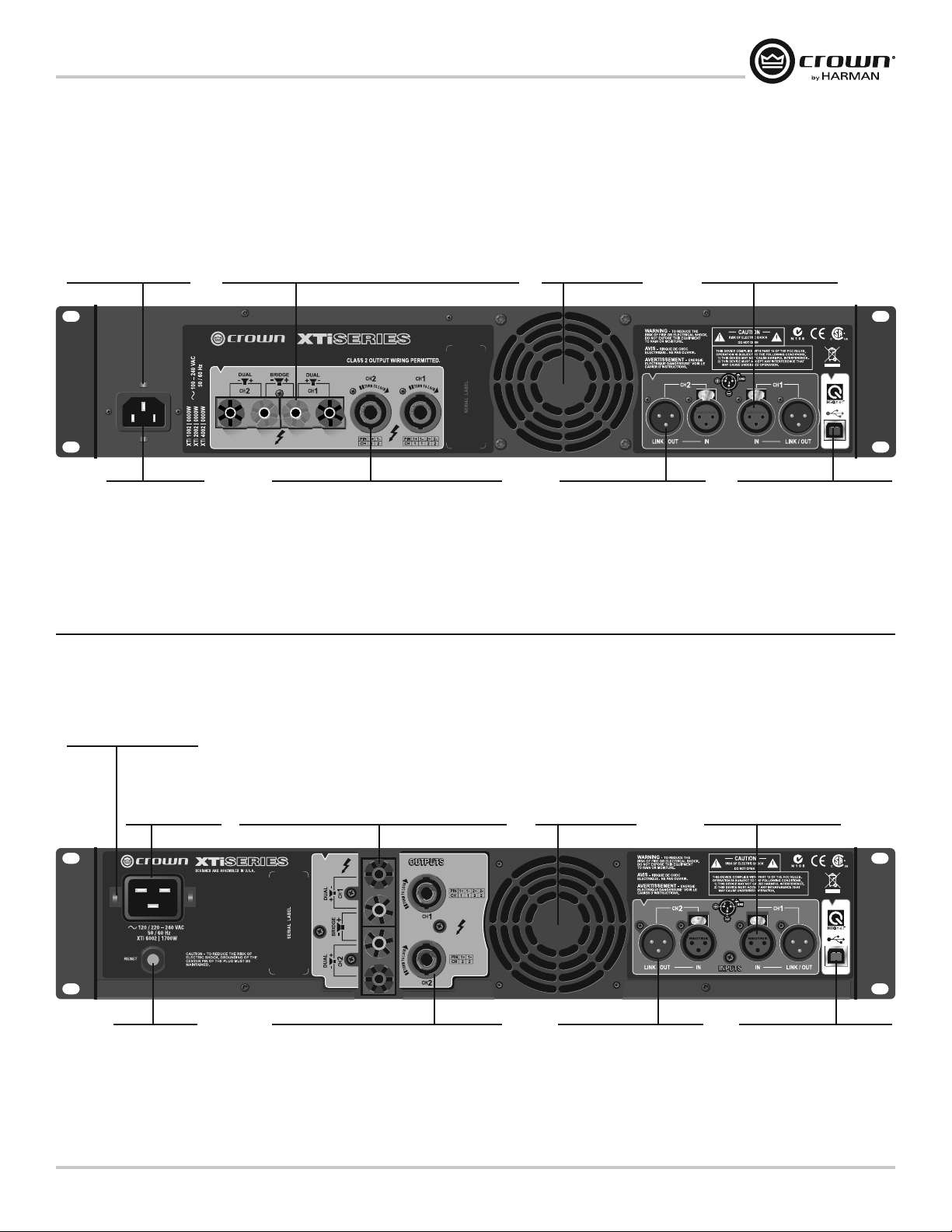
XTi2 Series Power Amplifiers
Caractéristiques panneau arrière
XTi 1002, 2002, 4002
Prises de sortie pour bornes de connexion :
Une paire par canal, accepte les prises banane ou un fil nu. Note
: les sorties pour bornes de connexion des modèles européens
sont livrées avec des prises de sécurité installées afin
Serre-câbles :
crochet de sécurité incluant
un serre-câbles
d’empêcher de faire pénétrer un objet quelconque dans les
prises d’alimentation européennes. Il est possible d'utiliser les
entrées latérales pour ces connecteurs sur l modèles européens.
Ventilateurs :
Garantissent un débit
d’air forcé d’avant
en arrière à titre de
refroidissement.
Connecteur d’entrée :
2 connecteurs d’entrée XLR à
3 branches sont fournis (un
par canal).
Prise
d’alimentation
CA
XTi 6002
Serre-câbles :
crochet de sécurité incluant
un serre-câbles
Prise
d’alimentation
CA
Prises de sortie 4 pôles Speakon® :
Ces deux prises acceptent les prises Speakon 2
ou 4 pôles. La prise Speakon du canal 1 est
câblée pour les deux canaux afin qu'il puisse être
utilisé pour le câblage Bridge-mono ou Stéréo des
deux haut-parleurs pour un seul Speakon.
Prises de sortie pour bornes de connexion :
Une paire par canal, accepte les prises banane ou un fil nu.
Note : les sorties pour bornes de connexion des modèles
européens sont livrées avec des prises de sécurité
installées afin d’empêcher de faire pénétrer un objet
quelconque dans les prises d’alimentation européennes. Il
est possible d'utiliser les entrées latérales pour ces
connecteurs sur l modèles européens.
Connecteur de
sortie/raccord :
2 connecteurs d’entrée XLR à 3
branches sont fournis (un par
canal) pour faire passer le signal
d’un amplificateur à un autre.
Ventilateurs :
Garantissent un débit
d’air forcé d’avant
en arrière à titre de
refroidissement.
Connecteur USB HiQnet :
ce connecteur USB de type B
permet de relier l’amplificateur à
un ordinateur pour utiliser les
logiciels System Architect™ et
Band Manager™.
Connecteur d’entrée :
2 connecteurs d’entrée XLR à
3 branches sont fournis (un
par canal).
Disjoncteur :
Protection contre
les surcharges
Operation Manual
Prises de sortie 4 pôles Speakon® :
Ces deux prises acceptent les prises Speakon 2
ou 4 pôles. La prise Speakon du canal 1 est
câblée pour les deux canaux afin qu'il puisse être
utilisé pour le câblage Bridge-mono ou Stéréo des
deux haut-parleurs pour un seul Speakon.
Connecteur de
sortie/raccord :
2 connecteurs d’entrée XLR à 3
branches sont fournis (un par
canal) pour faire passer le signal
d’un amplificateur à un autre.
Connecteur USB HiQnet :
ce connecteur USB de type B
permet de relier l’amplificateur à
un ordinateur pour utiliser les
logiciels System Architect™ et
Band Manager™.
page 39
Page 40

Fonctionnalités panneau avant
Sur le panneau avant, vous pouvez modifier les réglages de plusieurs caractéristiques intégrées de traitement du signal :
Entrée Y, Fréquence crossover, EQ, Delay, Limiting et Stereo/Bridge-Mono. Les icônes de l'écran s'illuminent lorsque les
fonctions correspondantes sont activées et allumées.
Lorsque vous allumez l'amplificateur pour la première fois, l'écran LCD affiche “DSP OFF” (DSP désactivé) Lors des
allumages suivants, l'écran affiche les préréglages actifs lors de la dernière utilisation de l'amplificateur.
Le schéma ci-dessous présente le menu avec la la liste des fonctionnalités disponibles Cela vous permet de naviguer
dans les réglages du panneau avant et de visualiser ceux qui sont disponibles. Pour accéder à toutes les fonctionnalités,
vous devez relier l'amplificateur à un ordinateur avec un câble USB et lancer le logiciel HiQnet System Architect™ ou Band
Manager™. Ces logiciels peuvent être téléchargés gratuitement à l'adresse suivante : http://hiqnet.harmanpro.com.
XTi2 Series Power Amplifiers
Menu
Allumag
PRÉRÉGLAGE ACTUEL
Sel
TEXTE « PRÉRÉGLAGE » CLIGNOTE
Sel
ICÔNE « PRÉRÉGLAGE » CLIGNOTE
Sel
PRÉRÉGLAGES
(TEXTE sur l’écran)
DSP OFF
Next
BRIDGE
Next
XOVER
Next
BRG SUBS
Next
SUB SYNTH
Next
USER PRESETS
6-50
Next
Sel
Après un certain délai, vous retournez
automatiquement au préréglage activé.
A partir du PRÉRÉGLAGE ACTIVÉ,
Sel > Sel > Suiv vous permet
d’accéder aux préréglages.
Sel>Suiv >Sel> vous permet
de congurer les procédés DSP.
Next (suiv)
or
Prev (préc)
Next
Procédés DSP
(ICONES sur l’écran)
Texte « Config »
Sel
CH1+CH2
Next
Next
INPUT Y
Y
STEREO
Sel
Next
XOV
Sel
EQ Ch. 1
Sel
EQ Ch. 2
Sel
DELAY Ch. 1
DELAY Ch. 2
LIM Ch. 1
LIM Ch. 2
STEREO/BRIDGE MONO
Next
Sel
Next
Sel
Next
Sel
Next
Sel
Sel
Appuyer sur Suiv pour
afficher toutes les options,
puis sur Sel pour
en sélectionner une
OFF, 90 Hz, 100 Hz, 1200 Hz,
1500 Hz, 2000 Hz, 2-CH SUB,
CUSTOM
Next
EQ OUT
EQ IN
Prev
Next
EQ OUT
EQ IN
Prev
CURRENT, OFF, 50, 40, 30,
20,10, 9, 8, 7, 6, 5, 4, 3, 2, 1
CURRENT, OFF, 50, 40, 30,
20,10, 9, 8, 7, 6, 5, 4, 3, 2, 1
CURRENT, OFF, –0.5 dB,
–1.0 dB, –1.5 dB... –40 dB
CURRENT, OFF, –0.5 dB,
–1.0 dB, –1.5 dB... –40 dB
Next
BRIDGE
STEREO
Prev
page 40
Naviguer dans le menu de l'écran LCD : Pour commencer
Pour naviguer parmi les options du menu, appuyer sur les boutons Sél, Suiv ou Préc décrits dans le schéma précédent.
Les icônes allumées en haut de l'écran vous indiquent les fonctions DSP actives dans le préréglage activé.
Lorsque vous modifiez un préréglage, les icônes correspondantes clignotent. Vous pouvez faire défiler les réglages avec
les boutons Préc et Suiv. Lorsque vous arrivez au réglage désiré, appuyez sur Sél pour l'enregistrer. Après 10 secondes
d'inactivité, vous retournez automatiquement au préréglage activé.
Si l'icone Préréglage est allumée sur l'écran LCD, la configuration initiale du préréglage activé n'a pas été modifiée. Si l'icône
Personnaliser est allumée, la configuration du préréglage activé a été modifiée.
Operation Manual
Page 41

XTi2 Series Power Amplifiers
Caractéristiques de traitement intégrées
L'amplificateur série XTi2 comprend une série de caractéristiques intégrées symbolisées par des icônes sur le panneau
avant de l'écran LCD. Elles sont décrites ci-dessous :
NOTE : Le logiciel System Architect est nécessaire pour manipuler toutes les caractéristiques de traitement intégrées
qui peuvent être téléchargées à l'adresse – http://hiqnet.harmanpro.com/. Pour gérer plusieurs modèles XTi2
à la fois, vous devez vous munir d'un concentrateur USB. Nous vous conseillons d'utiliser un concentrateur USB
auto-alimenté.
Mode d'entrée
t 4UÏSÏP EBOT DF NPEF MF DBOBM EhFOUSÏF FTU SFMJÏ BV DBOBM EF TPSUJF FU MF DBOBM EhFOUSÏF BV DBOBM EF TPSUJF .PEF QBS
défaut lorsque l'amplificateur sort de l'usine.
t 46. $) $) o EBOT DF NPEF MFT TJHOBVY EV DBOBM EhFOUSÏF FU EV DBOBM EhFOUSÏF TPOU BEEJUJPOOÏT FU FOWPZÏT
vers les deux canaux de sortie. Cela permet d'augmenter la puissance de 6 dB.
t *OQVU : EBOT DF NPEF MF TJHOBM EV DBOBM EhFOUSÏF FTU FOWPZÏ BVY DBOBVY EF TPSUJF FU -F TJHOBM EV DBOBM EhFOUSÏF
n'est pas transmis.
Mode de sortie.
t 4UÏSÏP EBOT DF NPEF MhBNQMJmDBUFVS FOWPZF MF TJHOBM EV DBOBM EhFOUSÏF BV DBOBM EF TPSUJF FU MF TJHOBM EV DBOBM
d'entrée 2 au canal de sortie 2.
t #SJEHF.POP o EBOT DF NPEF MB QVJTTBODF EFT EFVY DBOBVY FTU USBOTNJTF TPVT VOF SÏTJTUBODF EF PV PINT
Subharmonic Synth
La fonction Subharmonic Synth récupère les fréquences basses et les "synthétise" ou crée des nouvelles fréquences d'une
octave plus basses. Les deux signaux sont additionnés. Autre nouveauté, deux filtres paramétriques EQ réglables et un filtre
de fréquence crossover. Ces filtres peuvent être modifiés pour "envelopper" le son et produire l'effet désiré.
Égalisation
La série XTi2 fournit deux égaliseurs pour le traitement du signal. Le bloc EQ d'entrée est avant le crossover et généralement
utilisée pour le room-EQ. Le bloc EQ de sortie est après le crossover et généralement utilisé pour régler les haut-parleurs.
Entrée EQ : Le bloc d'entrée EQ fournit 6 filtres par canal, chacun avec une fréquence, un gain et une égalisation
personnalisable. Ce bloc a également un filtre coupe-bas et coupe-haut par canal pour contrôler le gain et la fréquence.
Sortie EQ : Le bloc de sortie EQ fournit 8 filtres par canal, chacun avec une fréquence, un gain et une
égalisation personnalisable.
Crossover :
La fonction crossover permet d'activer un filtre passe-bas et passe-haut par canal pour apporter un gain passe-bande et
modifier la polarité. La section crossover peut alors être personnalisée pour s'adapter à presque toutes les configurations.
Les filtres passe-bas et passe-haut peuvent être choisis parmi les modèles suivants : Butterworth 6 dB / oct, Butterworth 12
dB / oct, Butterworth 18 dB / oct, Butterworth 24 dB / oct, Butterworth 48 dB / oct, Linkwitz-Riley 24 dB / oct et Linkwitz-Riley
48 dB / oct.
Le filtre passe-bande apporte un gain de -15 dB à + 15 dB.
Delay
Il y a jusqu'à 50 m/s de delay disponible dans le traitement du signal pour aligner les hauts parleurs. Le logiciel permet
d'entrer le delay nécessaire en secondes, pieds ou mètres et effectue la conversion.
Operation Manual
PeakX Plus Limiter:
Limiteur feedforward à la sortie avec temps d'attaque et de retour et seuil personnalisable (résolution 0,1 db), plus limiteur
feedback intégré pour limiter l'écrêtage.
page 41
Page 42

Caractéristiques de traitement intégrées
Contrôle thermique perfectionné
Dans cette section, vous pouvez régler la vitesse du ventilateur pour l'adapter à une utilisation spécifique. Vous avez le choix
entre les modes suivants :
t OPSNBM
t SBQJEF
t USÒT SBQJEF
Le mode du ventilateur peut être modifié grâce aux boutons du panneau avant au démarrage ou par le biais du logiciel.
Le mode par défaut est sur vitesse normale et convient très bien à la plupart des applications. Le mode rapide accélère la
vitesse du ventilateur à une température plus "basse" et le mode très rapide apporte une vitesse maximale continue.
Le mode très rapide n'est pas recommandé dans un environnement dont les conditions d'hygiène ne sont pas optimales.
Commande perfectionnée
Cette fonction vous permet de consulter via le logiciel la température de fonctionnement et la tension composée alternative.
La tension alternative composée est "dérivée" de la tension de départ de l'amplificateur et est une approximation
de la tension alternative composée. Cela permet de surveiller l'état de votre amplificateur et d'éviter les problèmes.
Verrouillage panneau avant
Pour désactiver ou verrouiller les boutons du panneau avant, appuyez sur Préc et Suiv en même temps jusqu'à ce que l'écran
affiche "Verrouillé". Les sélecteur rotatifs (atténuateurs) pourront toujours fonctionner. Pour déverrouiller, appuyez sur Préc
et Suiv jusqu'à ce que l'écran affiche "Déverrouillé".
Le panneau avant et le panneau principal peuvent également être verrouillés à partir du logiciel. Un panneau verrouillé par le
logiciel ne peut être déverrouillé que par le logiciel. Il ne peut être deverrouillé avec les boutons du panneau. Les sélecteur
rotatifs (atténuateurs) pourront toujours fonctionner.
XTi2 Series Power Amplifiers
page 42
Operation Manual
Page 43

XTi2 Series Power Amplifiers
XTi2 Specications
Minimum Guaranteed Power, 1 kHz XTi 1002 XTi 2002 XTi 4002 XTi 6002
Per channel, both channels driven
Stereo, 2 ohms (per channel)
Stereo, 4 ohms (per channel)
Stereo, 8 ohms (per channel)
Bridge-Mono, 4 ohms
Bridge-Mono, 8 ohms
Performance
Sensitivity (volts RMS) for full rated power at 4 ohms: 1.4 V.
Frequency Response (at 1 watt into 4 ohms, 20 Hz to 20 kHz): +0 dB, –1 dB.
Signal to Noise Ratio (below rated 1 kHz power at 8 ohms), A-weighted: 100 dB (103 dB in XTi 6000).
Damping Factor (8 ohm) 10 Hz to 400 Hz: > 500.
Crosstalk (below rated power) 20 Hz to 1 kHz: > 70 dB.
Input Impedance (nominal): 20 kilohms balanced, 10 kilohms unbalanced.
Input Stage: Input is electronically balanced and employs pre cision 1% resistors.
AC Line Current (120VAC amplifier playing 1/8 power pink noise into 4 ohms per ch):
XTi 1002: 6.8A, XTi 2002: 8.3A, XTi 4002: 10.5A; at idle draws no more than 30 watts.
XTi 6002: 15.3A; at idle draws no more than 180 watts.
Voltage Gain (at 1 kHz, 8 ohm rated output): XTi 1002: 30.5 dB. XTi 2002: 32.9 dB. XTi 4002: 34.2 dB.
XTi 6002: 37.1 dB.
Maximum Imput Signal: +22 dBu typical.
Load impedance (note: safe with all types of loads)
Stereo: 2-8 ohms (4-8 ohms in XTi 1000 A1 100V versions).
Bridge-Mono: 4-16 ohms (8-16 ohms in XTi 1000 A1 100V versions).
AC Line Voltage and Frequency Configura tions Available (± 10%): 100V, 120V, 220-240V 50/60 Hz.
Operating Temperature: 0° C to 40° C at 95% relative humidity (non-condensing).
†
*
700W
500W
275W
1,400W
1,000W
*
1,000W
†
2,000W
1,600W
With 0.5% THD. *With 1% THD.
800W
475W
*
*
*
1,600W
1,200W
650W
*
3,200W
2,400W
†
Not rated for 100V versions.
3,000W
2,100W
1,200W
6,000W
4,200W
*
*
Operation Manual
Construction
Ventilation: Flow-through ventilation from front to back.
Cooling: Heat sinks and proportional-speed fan.
Dimensions. Width, Height, Depth (behind mounting surface):
EIA Standard 19 in. W (EIA RS-310-B) x 3.5 in. (8.9 cm) H x 12.25 in. (31.1cm) D. XTi 6000 is 16.2 in. (41.15 cm) D.
Weight
Net Weight, Shipping Weight: 18.5 lb (8.4 kg), 21.5 lb (9.8 kg). XTi 6002 is 24.0 lb (10.9 kg), 30.0 lb (13.6 kg).
page 43
Page 44

Service
XTi2 Series Power Amplifiers
Crown amplifiers are quality units that rarely require servicing. Before returning your unit for servicing, please contact Crown
Technical Support to verify the need for servicing.
Warranty is only valid within the country in which the product was purchased.
This unit has very sophisticated circuitry which should only be serviced by a fully trained technician. This is one reason why
each unit bears the following label:
CAUTION: To prevent electric shock, do not remove covers. No user serviceable parts inside. Refer
servicing to a qualified technician.
Complete the Crown Audio Factory Service Information form, in the back of this manual, when returning a Crown product
to the factory or authorized service center. The form must be included with your product inside the box or in a packing slip
envelope securely attached to the outside of the shipping carton. Do not send this form separately.
Worldwide Service
Service may be obtained from an authorized service center. (Contact your local Crown/Amcron representative or our office
for a list of authorized service centers.) To obtain service, simply present the bill of sale as proof of purchase along with the
defective unit to an authorized service center. They will handle the necessary paperwork and repair.
Remember to transport your unit in the original factory pack.
US and Canada Service
Service may be obtained in one of two ways: from an authorized service center or from the factory. You may choose either. It is
important that you have your copy of the bill of sale as your proof of purchase.
Service at a US or Canada Service Center
This method usually saves the most time and effort. Simply present your bill of sale along with the defective unit to an
authorized service center to obtain service. They will handle the necessary paperwork and repair. Remember to transport the
unit in the original factory pack. A list of authorized service centers in your area can be obtained from Crown Factory Service,
or online from http://www.crownaudio.com/support/servcent.htm.
Factory Service
Crown accepts no responsibility for non-serviceable product that is sent to us for factory repair. It is the owner’s responsibility
to ensure that their product is serviceable prior to sending it to the factory. Serviceable product list is available at
http://crownweb.crownintl.com/crownrma/.
For more information, please contact us direct.
A Service Return Authorization (SRA) is required for product being sent to the factory for repair. An SRA can be completed
online at www.crownaudio.com/support/factserv.htm. If you do not have access to the web, please call Crown’s Customer
Service at 574.294.8200 or 800.342.6939 extension 8205 in North America, Puerto Rico and the Virgin Islands only.
For warranty service, we will pay for ground shipping both ways in the United States. Contact Crown Customer Service to
obtain prepaid shipping labels prior to sending the unit. Or, if you prefer, you may prepay the cost of shipping, and Crown will
reimburse you. Send copies of the shipping receipts to Crown to receive reimbursement.
Your repaired unit will be returned via UPS ground. Please contact us if other arrangements are required.
page 44
Factory Service Shipping Instructions:
1. Service Return Authorization (SRA) is required for product being sent to the factory for service. Please complete the SRA
by going to www.crownaudio.com/support/factserv.htm. If you do not have access to our website, call 1.800.342.6939,
extension 8205 and we’ll create the SRA for you.
2. See packing instructions that follow.
Operation Manual
Page 45

XTi2 Series Power Amplifiers
Service
3. Ship product to:
4. Use a bold black marker and write the SRA number on three sides of the box.
5. Record the SRA number for future reference. The SRA number can be used to check the repair status.
Packing Instructions
Important: These instructions must be followed. If they are not followed, Crown Audio, Inc. assumes no responsibility for
damaged goods and/or accessories that are sent with your unit.
1. Fill out and include the Crown Audio Factory Service Information sheet in the back of this manual.
2. Do not ship any accessories (manuals, cords, hardware, etc.) with your unit. These items are not needed to service your
3. When shipping your Crown product, it is important that it has adequate protection. We recommend you use the original
4. If you provide your own shipping pack, the minimum recommended requirements for materials are as follows:
a. 275 P.S.I. burst test, Double-Wall carton that allows for 2-inch solid Styrofoam on all six sides of unit or 3 inches of
b. Securely seal the package with an adequate carton sealing tape.
c. Do not use light boxes or “peanuts”. Damage caused by poor packaging will not be covered under warranty.
Enclose the completed Crown Audio Factory Service Information form (or securely attach it to the outside of carton)
and re-seal the shipping pack with a sturdy carton sealing tape.
CROWN AUDIO FACTORY SERVICE
1718 W MISHAWKA RD.
ELKHART, IN 46517
product. We will not be responsible for these items.
pack material when returning the product for repair (Figure 9.1). If you do not have the original box, please call Crown at
800.342.6939 or 574.294.8210 and order new pack material. (Do not ship your unit in a wood or metal cabinet.)
plastic bubble wrap on all six sides of unit.
Estimate Approval
Approval of estimate must be given within 30 days after being notified by Crown Audio Inc. Units still in the possession of
Crown after 30 days of the estimate will become the property of Crown Audio Inc.
Payment of Non-Warranty Repairs
Payment on out-of-warranty repairs must be received within 30 days of the repair date. Units unclaimed after 30 days become
the property of Crown Audio Inc.
If you have any questions, please contact Crown Factory Service.
Crown Factory Service
1718 W. Mishawaka Rd.,
Elkhart, Indiana 46517 U.S.A.
Telephone:
574-294-8200
800-342-6939 (North America, Puerto Rico, and Virgin Islands only)
Facsimile:
574-294-8301 (Technical Support)
574-294-8124 (Factory Service)
Web site:
http://www.crownaudio.com
Operation Manual
page 45
Page 46

Warranty — UNITED STATES & CANADA
SUMMARY OF WARRANTY
Crown International, 1718 West Mishawaka Road, Elkhart, Indiana 46517-4095 U.S.A. warrants to you, the ORIGINAL
PURCHASER and ANY SUBSEQUENT OWNER of each NEW Crown product, for a period of three (3) years from the date of
purchase by the original purchaser (the “warranty period”) that the new Crown product is free of defects in materials and
workmanship. We further warrant the new Crown product regardless of the reason for failure, except as excluded in this
Warranty.
Warranty is only valid within the country in which the product was purchased.
ITEMS EXCLUDED FROM THIS CROWN WARRANTY
This Crown Warranty is in effect only for failure of a new Crown product which occurred within the Warranty Period. It does not
cover any product which has been damaged because of any intentional misuse, accident, negligence, or loss which is covered
under any of your insurance contracts. This Crown Warranty also does not extend to the new Crown product if the serial
number has been defaced, altered, or removed.
WHAT THE WARRANTOR WILL DO
We will remedy any defect, regardless of the reason for failure (except as excluded), by repair, replacement, or refund. We may
not elect refund unless you agree, or unless we are unable to provide replacement, and repair is not practical or cannot be
timely made. If a refund is elected, then you must make the defective or malfunctioning product available to us free and clear
of all liens or other encumbrances. The refund will be equal to the actual purchase price, not including interest, insurance,
closing costs, and other finance charges less a reasonable depreciation on the product from the date of original purchase.
Warranty work can only be performed at our authorized service centers or at the factory. We will remedy the defect and ship the
product from the service center or our factory within a reasonable time after receipt of the defective product at our authorized
service center or our factory. All expenses in remedying the defect, including surface shipping costs in the United States, will
be borne by us. (You must bear the expense of shipping the product between any foreign country and the port of entry in the
United States including the return shipment, and all taxes, duties, and other customs fees for such foreign shipments.)
XTi2 Series Power Amplifiers
HOW TO OBTAIN WARRANTY SERVICE
You must notify us of your need for warranty service within the warranty period. All components must be shipped in a factory
pack, which, if needed, may be obtained from us free of charge. Corrective action will be taken within a reasonable time of
the date of receipt of the defective product by us or our authorized service center. If the repairs made by us or our authorized
service center are not satisfactory, notify us or our authorized service center immediately.
DISCLAIMER OF CONSEQUENTIAL AND INCIDENTAL DAMAGES
YOU ARE NOT ENTITLED TO RECOVER FROM US ANY INCIDENTAL DAMAGES RESULTING FROM ANY DEFECT IN THE
NEW CROWN PRODUCT. THIS INCLUDES ANY DAMAGE TO ANOTHER PRODUCT OR PRODUCTS RESULTING FROM
SUCH A DEFECT. SOME STATES DO NOT ALLOW THE EXCLUSION OR LIMITATIONS OF INCIDENTAL OR CONSEQUENTIAL
DAMAGES, SO THE ABOVE LIMITATION OR EXCLUSION MAY NOT APPLY TO YOU.
WARRANTY ALTERATIONS
No person has the authority to enlarge, amend, or modify this Crown Warranty. This Crown Warranty is not extended by the
length of time which you are deprived of the use of the new Crown product. Repairs and replacement parts provided under the
terms of this Crown Warranty shall carry only the unexpired portion of this Crown Warranty.
DESIGN CHANGES
We reserve the right to change the design of any product from time to time without notice and with no obligation to make
corresponding changes in products previously manufactured.
LEGAL REMEDIES OF PURCHASER
THIS CROWN WARRANTY GIVES YOU SPECIFIC LEGAL RIGHTS, YOU MAY ALSO HAVE OTHER RIGHTS WHICH VARY
FROM STATE TO STATE. No action to enforce this Crown Warranty shall be commenced after expiration of the warranty period.
THIS STATEMENT OF WARRANTY SUPERSEDES ANY OTHERS CONTAINED IN THIS MANUAL FOR CROWN PRODUCTS.
12/09
page 46
Operation Manual
Page 47

XTi2 Series Power Amplifiers
Warranty — WORLDWIDE EXCEPT USA & CANADA
SUMMARY OF WARRANTY
Crown International, 1718 West Mishawaka Road, Elkhart, Indiana 46517-4095 U.S.A. warrants to you, the ORIGINAL
PURCHASER and ANY SUBSEQUENT OWNER of each NEW Crown
of purchase by the original purchaser (the “warranty period”) that the new Crown product is free of defects in materials and
workmanship, and we further warrant the new Crown product regardless of the reason for failure, except as excluded in this
Warranty.
Warranty is only valid within the country in which the product was purchased.
1
Note: If your unit bears the name “Amcron,” please substitute it for the name “Crown” in this warranty.
ITEMS EXCLUDED FROM THIS CROWN WARRANTY
This Crown Warranty is in effect only for failure of a new Crown product which occurred within the Warranty Period. It does not
cover any product which has been damaged because of any intentional misuse, accident, negligence, or loss which is covered
under any of your insurance contracts. This Crown Warranty also does not extend to the new Crown product if the serial
number has been defaced, altered, or removed.
WHAT THE WARRANTOR WILL DO
We will remedy any defect, regardless of the reason for failure (except as excluded), by repair, replacement, or refund. We may
not elect refund unless you agree, or unless we are unable to provide replacement, and repair is not practical or cannot be
timely made. If a refund is elected, then you must make the defective or malfunctioning product available to us free and clear
of all liens or other encumbrances. The refund will be equal to the actual purchase price, not including interest, insurance,
closing costs, and other finance charges less a reasonable depreciation on the product from the date of original purchase.
Warranty work can only be performed at our authorized service centers. We will remedy the defect and ship the product from
the service center within a reasonable time after receipt of the defective product at our authorized service center.
1
product, for a period of three (3) years from the date
HOW TO OBTAIN WARRANTY SERVICE
You must notify your local Crown importer of your need for warranty service within the warranty period. All components must
be shipped in the original box. Corrective action will be taken within a reasonable time of the date of receipt of the defective
product by our authorized service center. If the repairs made by our authorized service center are not satisfactory, notify our
authorized service center immediately.
DISCLAIMER OF CONSEQUENTIAL AND INCIDENTAL DAMAGES
YOU ARE NOT ENTITLED TO RECOVER FROM US ANY INCIDENTAL DAMAGES RESULTING FROM ANY DEFECT IN THE
NEW CROWN PRODUCT. THIS INCLUDES ANY DAMAGE TO ANOTHER PRODUCT OR PRODUCTS RESULTING FROM SUCH
A DEFECT.
WARRANTY ALTERATIONS
No person has the authority to enlarge, amend, or modify this Crown Warranty. This Crown Warranty is not extended by the
length of time which you are deprived of the use of the new Crown product. Repairs and replacement parts provided under the
terms of this Crown Warranty shall carry only the unexpired portion of this Crown Warranty.
DESIGN CHANGES
We reserve the right to change the design of any product from time to time without notice and with no obligation to make
corresponding changes in products previously manufactured.
LEGAL REMEDIES OF PURCHASER
No action to enforce this Crown Warranty shall be commenced after expiration of the warranty period.
THIS STATEMENT OF WARRANTY SUPERSEDES ANY OTHERS CONTAINED IN THIS MANUAL FOR CROWN PRODUCTS.
12/09
Operation Manual
page 47
Page 48

XTi2 Series Power Amplifiers
THIS PAGE INTENTIONALLY LEFT BLANK
page 48
Operation Manual
Page 49

XTi2 Series Power Amplifiers
PRODUCT REGISTRATION
Online registration is also available at http://crownweb.crownintl.com/webregistration.
Warranty is only valid within the country in which the product is purchased.
When this form is used to register your product, it may be mailed or faxed.
Crown Audio, Inc. Fax: 574-294-8329
1718 W Mishawaka Rd
Elkhart IN 46517
Please note that some information is required. Incomplete registrations will not be processed. * Indicates required information.
OWNER’S INFORMATION – PLEASE PRINT
* First name: ____________________________ Middle initial:______ * Last name:____________________________________________________
Company: ___________________________________________________________________________________________________________
* Mailing address: _______________________________________________________________________________________________________
* City: _____________________________________ * State:_______ * Zip Code:____________________________________________________
* Country: ____________________________ E-mail address:____________________________________________________________________
* Phone # (include area code): _____________________________________ Fax #:____________________________________________________
Crown Audio, Inc.
1718 W. Mishawaka Rd.
Elkhart, IN 46517-9439
Phone: 574-294-8000
Fax: 574-294-8329
www.crownaudio.com
CUT ON THIS LINE
* MODEL * SERIAL # * PURCHASE DATE
e.g. IT8000, CDi1000, PCC16 e.g. 800000000 mo/day/yr
____________________________________ _____________________________ ____ / ____ / ____
____________________________________ _____________________________ ____ / ____ / ____
____________________________________ _____________________________ ____ / ____ / ____
____________________________________ _____________________________ ____ / ____ / ____
Product purchased from: *(Business/Individual) _______________________________________ Country:____________________________________
Comments: ___________________________________________________________________________________________________________
____________________________________________________________________________________________________________________
____________________________________________________________________________________________________________________
PRODUCT INFORMATION
Operation Manual
page 49
Page 50

XTi2 Series Power Amplifiers
THIS PAGE INTENTIONALLY LEFT BLANK
page 50
Operation Manual
Page 51

XTi2 Series Power Amplifiers
Crown Audio Factory Service Information
Shipping Address: Crown Audio Factory Service, 1718 W. Mishawaka Rd., Elkhart, IN 46517
PLEASE PRINT CLEARLY
SRA #: ______________________ (If sending product to Crown factory service.)
Model: ______________________ Serial Number: _________________________ Purchase Date: ____________________
PRODUCT RETURN INFORMATION
Individual or Business Name: ___________________________________________________________________________________________________
Phone #: ____________________________ Fax #:__________________________________ E-Mail:________________________________________
Street Address (please, no P.O. Boxes): ____________________________________________________________________________________________
City: ___________________________ State/Prov:_______________ Postal Code: ________________ Country:________________________________
Nature of problem: __________________________________________________________________________________________________________
________________________________________________________________________________________________________________________
________________________________________________________________________________________________________________________
________________________________________________________________________________________________________________________
________________________________________________________________________________________________________________________
Other equipment in your system: ________________________________________________________________________________________________
If warranty is expired, please provide method of payment. Proof of purchase may be required to validate warranty.
PAYMENT OPTIONS
I have open account payment terms. Purchase order required. PO#: _____________________________ COD
Credit Card (Information below is required; however if you do not want to provide this information at this time, we will contact you when your unit is repaired for the
information.)
Credit card information:
Type of credit card:
Type of credit card account:
Card # _______________________________________ Exp. date: ________________ *Card ID #: _______
* Card ID # is located on the back of the card following the credit card #, in the signature area. On American Express, it may be located on the front of the card. This number is required to
process the charge to your account. If you do not want to provide it at this time, we will call you to obtain this number when the repair of your unit is complete.
Name on credit card: _____________________________________
Billing address of credit card: ______________________________
______________________________
______________________________
MasterCard Visa American Express Discover
Personal/Consumer Business/Corporate
Operation Manual
page 51
Page 52

 Loading...