

Crown TC 3000 Series, TC 3000-3.0 Maintenance Manual

M
Revision: A • Printed in Germany
MAINTENANCE MANUAL
TC 3000 SERIES
Order Number: 812573-006

Thi
s master manual is subject to continual updates.
It is intended solely for companies authorised by CROWN.
The distribution of its content or copies thereof to third parties is prohibited.
CROWN Gabelstapler GmbH & Co. KG
– European Headquarters –
Moosacher Str. 52
80809 München
Germany
Tel +49 (0)89 93 00 2 – 0
Fax +49 (0)89 93 00 2 – 133
All rights reserved under international and Pan-American Copyright Agreement.
Copyright 2008
CROWN Equipment Corporation

I
TABLE OF CONTENTS

II
Notes:

TABLE OF CONTENTS
III
TC 3000
TABLE OF CONTENTS
SAFETY PAGE SERIAL NO. CUT REV.
Description of Symbols and Indicators . . . . . . . . . . . . . . . . . . 3
Safety Notices . . . . . . . . . . . . . . . . . . . . . . . . . . . . . . . . . . . . . 3
Other indicators . . . . . . . . . . . . . . . . . . . . . . . . . . . . . . . . . . . . 3
General Safety Instructions . . . . . . . . . . . . . . . . . . . . . . . . . . . . 4
Maintenance and Repair Instructions . . . . . . . . . . . . . . . . . . . 4
Maintenance and Repairs . . . . . . . . . . . . . . . . . . . . . . . . . . . . 4
Before Parking the Truck . . . . . . . . . . . . . . . . . . . . . . . . . . . . . 4
Before Working on the Truck . . . . . . . . . . . . . . . . . . . . . . . . . . 4
Before Starting the Truck . . . . . . . . . . . . . . . . . . . . . . . . . . . . . 4
Warning and Instruction Decals on the Truck . . . . . . . . . . . . . 5
INTRODUCTION PAGE SERIAL NO. CUT REV.
General . . . . . . . . . . . . . . . . . . . . . . . . . . . . . . . . . . . . . . . . . . . . . 9
Service Training . . . . . . . . . . . . . . . . . . . . . . . . . . . . . . . . . . . . 9
Replacement Parts . . . . . . . . . . . . . . . . . . . . . . . . . . . . . . . . . 9
Additional Attachments and Modifications . . . . . . . . . . . . . . . . 9
Using the Manual . . . . . . . . . . . . . . . . . . . . . . . . . . . . . . . . . . . 9
Contact Address . . . . . . . . . . . . . . . . . . . . . . . . . . . . . . . . . . . 9
Models . . . . . . . . . . . . . . . . . . . . . . . . . . . . . . . . . . . . . . . . . . . . 10
LUBRICATION & ADJUSTMENT PAGE SERIAL NO. CUT REV.
Lifting and Jacking up the Truck . . . . . . . . . . . . . . . . . . . . . . . 13
Lifting the Truck . . . . . . . . . . . . . . . . . . . . . . . . . . . . . . . . . . . 13
Lifting the truck with a crane . . . . . . . . . . . . . . . . . . . . . . . 13
Lifting the truck with a forklift truck . . . . . . . . . . . . . . . . . . 13
Jacking up the Truck . . . . . . . . . . . . . . . . . . . . . . . . . . . . . . . 14
Towing the Truck . . . . . . . . . . . . . . . . . . . . . . . . . . . . . . . . . . . . 15
Taking the Truck out of Service . . . . . . . . . . . . . . . . . . . . . . . . 16
Testing Re-Commissioned Trucks . . . . . . . . . . . . . . . . . . . . . 16
Restoring the Truck to Service . . . . . . . . . . . . . . . . . . . . . . . . 16
Recommended Lubricants and Accessories . . . . . . . . . . . . . 17
Cold Store Trucks . . . . . . . . . . . . . . . . . . . . . . . . . . . . . . . . . 17
Planned Maintenance . . . . . . . . . . . . . . . . . . . . . . . . . . . . . . . . 19
Inspection and Lubrication Points . . . . . . . . . . . . . . . . . . . . . 22
Torques . . . . . . . . . . . . . . . . . . . . . . . . . . . . . . . . . . . . . . . . . . . 24
Standard Torques . . . . . . . . . . . . . . . . . . . . . . . . . . . . . . . . . . 24
Castor Wheels and Skids . . . . . . . . . . . . . . . . . . . . . . . . . . . . . 25
Adjusting the Castor Wheels and Skids . . . . . . . . . . . . . . . . . 26
DRIVE UNIT PAGE SERIAL NO. CUT REV.
Changing the Transmission Oil . . . . . . . . . . . . . . . . . . . . . . . . 29
Components . . . . . . . . . . . . . . . . . . . . . . . . . . . . . . . . . . . . . . . 31
Replacing the Output Shaft Seal . . . . . . . . . . . . . . . . . . . . . . . 32
Special Tools Required . . . . . . . . . . . . . . . . . . . . . . . . . . . . 33
Preparation . . . . . . . . . . . . . . . . . . . . . . . . . . . . . . . . . . . . . . 33
Shaft Seal Removal . . . . . . . . . . . . . . . . . . . . . . . . . . . . . . . . 33
Output shaft removal . . . . . . . . . . . . . . . . . . . . . . . . . . . . 33
Output shaft assembly . . . . . . . . . . . . . . . . . . . . . . . . . . . 33

TABLE OF CONTENTS
IV
TC 3000
Drive Wheel and Wheel Bolt Replacement . . . . . . . . . . . . . . .35
Drive Wheel Disassembly . . . . . . . . . . . . . . . . . . . . . . . . . . . .35
Replacing the Wheel Bolts . . . . . . . . . . . . . . . . . . . . . . . . . . .35
Drive Wheel Assembly . . . . . . . . . . . . . . . . . . . . . . . . . . . . . .35
Replacing the Drive Unit . . . . . . . . . . . . . . . . . . . . . . . . . . . . . .36
Special Tools Required . . . . . . . . . . . . . . . . . . . . . . . . . . . . .36
Drive Unit Removal . . . . . . . . . . . . . . . . . . . . . . . . . . . . . . . . .36
Drive Unit Installation . . . . . . . . . . . . . . . . . . . . . . . . . . . . . . .36
Repairing the Drive Transmission Unit . . . . . . . . . . . . . . . . . .37
Preparation . . . . . . . . . . . . . . . . . . . . . . . . . . . . . . . . . . . . . . .38
Drive Transmission Unit Disassembly . . . . . . . . . . . . . . . . . . .38
Output shaft removal . . . . . . . . . . . . . . . . . . . . . . . . . . . . .38
Bevel gear and bevel pinion removal . . . . . . . . . . . . . . . . .38
Drive Transmission Unit Assembly . . . . . . . . . . . . . . . . . . . . .39
Bevel pinion and drive pinion assembly . . . . . . . . . . . . . . .39
Bevel gear assembly . . . . . . . . . . . . . . . . . . . . . . . . . . . . .40
ELECTRICAL SYSTEM PAGE SERIAL NO. CUT REV.
General . . . . . . . . . . . . . . . . . . . . . . . . . . . . . . . . . . . . . . . . . . . .45
Wire Colour Code . . . . . . . . . . . . . . . . . . . . . . . . . . . . . . . . . .45
Contact Symbol Abbreviations . . . . . . . . . . . . . . . . . . . . . . . . .46
Electrical Wiring Diagrams . . . . . . . . . . . . . . . . . . . . . . . . . . . .48
Components . . . . . . . . . . . . . . . . . . . . . . . . . . . . . . . . . . . . . . . . 50
Operator Menu . . . . . . . . . . . . . . . . . . . . . . . . . . . . . . . . . . . . . . 54
Operator Menu . . . . . . . . . . . . . . . . . . . . . . . . . . . . . . . . . . . . . . 55
Service Menu . . . . . . . . . . . . . . . . . . . . . . . . . . . . . . . . . . . . . . .56
Analyzer Menu - Status & Inputs . . . . . . . . . . . . . . . . . . . . . . .57
Analyzer Menu - Outputs . . . . . . . . . . . . . . . . . . . . . . . . . . . .58
Analyzer Menu - Access 2 Inputs . . . . . . . . . . . . . . . . . . . . . .60
Analyzer Menu - Access 3 Inputs . . . . . . . . . . . . . . . . . . . . . .61
Analyzer Menu - Access 3 Inputs . . . . . . . . . . . . . . . . . . . . . .62
Analyzer Menu - Access 5 Inputs . . . . . . . . . . . . . . . . . . . . . .63
Analyzer Menu - Test Outputs . . . . . . . . . . . . . . . . . . . . . . . . .64
Calibration - Rocker & Load Sensor . . . . . . . . . . . . . . . . . . . .65
Calibration - Steer System . . . . . . . . . . . . . . . . . . . . . . . . . . .66
Features . . . . . . . . . . . . . . . . . . . . . . . . . . . . . . . . . . . . . . . . .67
Features . . . . . . . . . . . . . . . . . . . . . . . . . . . . . . . . . . . . . . . . .68
Features . . . . . . . . . . . . . . . . . . . . . . . . . . . . . . . . . . . . . . . . .69
Features . . . . . . . . . . . . . . . . . . . . . . . . . . . . . . . . . . . . . . . . .70
Features . . . . . . . . . . . . . . . . . . . . . . . . . . . . . . . . . . . . . . . . .71
Hours . . . . . . . . . . . . . . . . . . . . . . . . . . . . . . . . . . . . . . . . . . .72
Events . . . . . . . . . . . . . . . . . . . . . . . . . . . . . . . . . . . . . . . . . . .73
Events . . . . . . . . . . . . . . . . . . . . . . . . . . . . . . . . . . . . . . . . . . .74
Performance . . . . . . . . . . . . . . . . . . . . . . . . . . . . . . . . . . . . . .75
Performance . . . . . . . . . . . . . . . . . . . . . . . . . . . . . . . . . . . . . .76
Performance . . . . . . . . . . . . . . . . . . . . . . . . . . . . . . . . . . . . . .77
Performance . . . . . . . . . . . . . . . . . . . . . . . . . . . . . . . . . . . . . .78
Performance . . . . . . . . . . . . . . . . . . . . . . . . . . . . . . . . . . . . . .79
Utilities . . . . . . . . . . . . . . . . . . . . . . . . . . . . . . . . . . . . . . . . . .80
Parameter Setting . . . . . . . . . . . . . . . . . . . . . . . . . . . . . . . . . . .81
Calibration . . . . . . . . . . . . . . . . . . . . . . . . . . . . . . . . . . . . . . . . .82
Selecting the CALIBRATION Menu . . . . . . . . . . . . . . . . . . . .82
Calibrating the Traction Potentiometer . . . . . . . . . . . . . . . . . .82
Steering Calibration . . . . . . . . . . . . . . . . . . . . . . . . . . . . . . . . .82

TABLE OF CONTENTS
V
TC 3000
Control Modules . . . . . . . . . . . . . . . . . . . . . . . . . . . . . . . . . . . . 84
General . . . . . . . . . . . . . . . . . . . . . . . . . . . . . . . . . . . . . . . . . 84
Power Fuses . . . . . . . . . . . . . . . . . . . . . . . . . . . . . . . . . . . . . 84
Servicing and Replacing the Control Modules . . . . . . . . . . . 85
Discharging the Capacitors . . . . . . . . . . . . . . . . . . . . . . . . . . 85
Servicing the Control Modules . . . . . . . . . . . . . . . . . . . . . . . . 85
Replacing Control Modules . . . . . . . . . . . . . . . . . . . . . . . . . . 85
Removal . . . . . . . . . . . . . . . . . . . . . . . . . . . . . . . . . . . . . . 85
Assembly . . . . . . . . . . . . . . . . . . . . . . . . . . . . . . . . . . . . . 85
Event Codes - Access 3 . . . . . . . . . . . . . . . . . . . . . . . . . . . . . . 87
Event Codes - Access 5 . . . . . . . . . . . . . . . . . . . . . . . . . . . . . . 94
Drive Motor . . . . . . . . . . . . . . . . . . . . . . . . . . . . . . . . . . . . . . . 102
Drive Motor Disassembly . . . . . . . . . . . . . . . . . . . . . . . . . . . 103
Drive Motor Assembly . . . . . . . . . . . . . . . . . . . . . . . . . . . . . 103
Repairing the Drive Motor . . . . . . . . . . . . . . . . . . . . . . . . . . 104
Preparation . . . . . . . . . . . . . . . . . . . . . . . . . . . . . . . . . . . 104
Dismantling the Rotor Assembly . . . . . . . . . . . . . . . . . . . 104
Assembling the Rotor Assembly . . . . . . . . . . . . . . . . . . . 104
Final task: . . . . . . . . . . . . . . . . . . . . . . . . . . . . . . . . . . . . 104
Steer Motor . . . . . . . . . . . . . . . . . . . . . . . . . . . . . . . . . . . . . . . 105
Special Tools Required . . . . . . . . . . . . . . . . . . . . . . . . . . . . 106
Steer Motor Disassembly . . . . . . . . . . . . . . . . . . . . . . . . . . . 106
Steer Motor Assembly . . . . . . . . . . . . . . . . . . . . . . . . . . . . . 106
Repairing the Steer Motor . . . . . . . . . . . . . . . . . . . . . . . . . . 106
Preparation . . . . . . . . . . . . . . . . . . . . . . . . . . . . . . . . . . . 106
Steer Motor Disassembly . . . . . . . . . . . . . . . . . . . . . . . . 106
Steer Motor Assembly . . . . . . . . . . . . . . . . . . . . . . . . . . . 106
Final tasks: . . . . . . . . . . . . . . . . . . . . . . . . . . . . . . . . . . . 106
Battery . . . . . . . . . . . . . . . . . . . . . . . . . . . . . . . . . . . . . . . . . . . 107
General . . . . . . . . . . . . . . . . . . . . . . . . . . . . . . . . . . . . . . . . 107
Charging the Battery . . . . . . . . . . . . . . . . . . . . . . . . . . . . . . 107
Replacing the Battery . . . . . . . . . . . . . . . . . . . . . . . . . . . . . . 107
Contactors - Inspection and Repairs . . . . . . . . . . . . . . . . . . 108
Inspection . . . . . . . . . . . . . . . . . . . . . . . . . . . . . . . . . . . . . . 108
Contacts . . . . . . . . . . . . . . . . . . . . . . . . . . . . . . . . . . . . . 108
Coils . . . . . . . . . . . . . . . . . . . . . . . . . . . . . . . . . . . . . . . . 108
Springs . . . . . . . . . . . . . . . . . . . . . . . . . . . . . . . . . . . . . . 108
Servicing . . . . . . . . . . . . . . . . . . . . . . . . . . . . . . . . . . . . . . . 109
Dismantling . . . . . . . . . . . . . . . . . . . . . . . . . . . . . . . . . . . 109
Assembly . . . . . . . . . . . . . . . . . . . . . . . . . . . . . . . . . . . . 109
Control Module Safety Test . . . . . . . . . . . . . . . . . . . . . . . . . . 110
General . . . . . . . . . . . . . . . . . . . . . . . . . . . . . . . . . . . . . . . . 110
Required tools . . . . . . . . . . . . . . . . . . . . . . . . . . . . . . . . . . . 110
Carrying out the PMT . . . . . . . . . . . . . . . . . . . . . . . . . . . . . . 110
Testing Access 3 (TCM) . . . . . . . . . . . . . . . . . . . . . . . . . 110
Testing Access 5 (SCM) . . . . . . . . . . . . . . . . . . . . . . . . . 110
BRAKE SYSTEM PAGE SERIAL NO. CUT REV.
Electromechanical Brake . . . . . . . . . . . . . . . . . . . . . . . . . . . . 115
General . . . . . . . . . . . . . . . . . . . . . . . . . . . . . . . . . . . . . . . . 115
Servicing the Brake . . . . . . . . . . . . . . . . . . . . . . . . . . . . . . . 115
Measuring the air gap . . . . . . . . . . . . . . . . . . . . . . . . . . . 115
Repairing the Brake . . . . . . . . . . . . . . . . . . . . . . . . . . . . . . . 116
Installing a wear part kit . . . . . . . . . . . . . . . . . . . . . . . . . 116

TABLE OF CONTENTS
VI
TC 3000
Replacing the brake in full . . . . . . . . . . . . . . . . . . . . . . . . 118
STEERING PAGE SERIAL NO. CUT REV.
Steering Assembly Installation and Removal . . . . . . . . . . . .123
Steering Assembly Components . . . . . . . . . . . . . . . . . . . . . .124
Steering Assembly Removal . . . . . . . . . . . . . . . . . . . . . . . . .124
Steering Assembly Installation . . . . . . . . . . . . . . . . . . . . . . .124
Final Tasks . . . . . . . . . . . . . . . . . . . . . . . . . . . . . . . . . . . . . .124
Steering Transmission Repair . . . . . . . . . . . . . . . . . . . . . . . .125
Preparation . . . . . . . . . . . . . . . . . . . . . . . . . . . . . . . . . . . . . .125
Steering Transmission Disassembly . . . . . . . . . . . . . . . . . . . 125
Steering Transmission Assembly . . . . . . . . . . . . . . . . . . . . .125
Final tasks . . . . . . . . . . . . . . . . . . . . . . . . . . . . . . . . . . . . . . .126
Tiller Handle Components . . . . . . . . . . . . . . . . . . . . . . . . . . . .127
Tiller Handle Shell Removal and Assembly . . . . . . . . . . . . . .128
Tools Required . . . . . . . . . . . . . . . . . . . . . . . . . . . . . . . . . . .128
Preparation . . . . . . . . . . . . . . . . . . . . . . . . . . . . . . . . . . .128
Shell Removal . . . . . . . . . . . . . . . . . . . . . . . . . . . . . . . . . . . . 128
Shell Assembly . . . . . . . . . . . . . . . . . . . . . . . . . . . . . . . . . . .129
Switch Unit Removal / Assembly . . . . . . . . . . . . . . . . . . . . . .130
Components . . . . . . . . . . . . . . . . . . . . . . . . . . . . . . . . . . . . .130
Switch Unit Disassembly . . . . . . . . . . . . . . . . . . . . . . . . . . . .130
Switch Unit Assembly . . . . . . . . . . . . . . . . . . . . . . . . . . . . . .130
"Rabbit / Turtle" Toggle Module Removal and Assembly . .131
“Rabbit/Turtle” Toggle Module Disassembly . . . . . . . . . . . . .131
“Rabbit/Turtle” Toggle Module Assembly . . . . . . . . . . . . . . .131
Replacing the Tiller Handle PC Boards . . . . . . . . . . . . . . . . .132
Hydraulic PC Board Removal . . . . . . . . . . . . . . . . . . . . . . . .132
Hydraulic PC Board Assembly . . . . . . . . . . . . . . . . . . . . . . .132
Main PC Board Disassembly . . . . . . . . . . . . . . . . . . . . . . . .132
Main PC Board Assembly . . . . . . . . . . . . . . . . . . . . . . . . . . .132
Traction Potentiometer Removal and Assembly
(POT Travel Switch) . . . . . . . . . . . . . . . . . . . . . . . . . . . . . . . . . 133
Traction Potentiometer Removal . . . . . . . . . . . . . . . . . . . . . . 133
Traction Potentiometer Assembly . . . . . . . . . . . . . . . . . . . . .134
Traction Potentiometer Calibration . . . . . . . . . . . . . . . . . . . .134
Safety Reverse Switch Removal and Assembly . . . . . . . . . . 135
Safety Reverse Switch Removal . . . . . . . . . . . . . . . . . . . . . .135
Safety Reverse Switch Assembly . . . . . . . . . . . . . . . . . . . . .136
Grip and Horn Switch Removal and Assembly . . . . . . . . . . .137
Control Handle Overview . . . . . . . . . . . . . . . . . . . . . . . . . . . .138
Tiller Removal / Assembly . . . . . . . . . . . . . . . . . . . . . . . . . . . .139
Tiller Removal . . . . . . . . . . . . . . . . . . . . . . . . . . . . . . . . . . . .139
Tiller Assembly . . . . . . . . . . . . . . . . . . . . . . . . . . . . . . . . . . .139
Tiller Recuperating Spring Removal / Assembly . . . . . . . . .140
Recuperating Spring Removal . . . . . . . . . . . . . . . . . . . . . . . 140
Recuperating Spring Assembly . . . . . . . . . . . . . . . . . . . . . . .140
Steer Sensor Removal / Assembly . . . . . . . . . . . . . . . . . . . . . 141
Steer Sensor Removal . . . . . . . . . . . . . . . . . . . . . . . . . . . . .141
Steer Sensor Assembly . . . . . . . . . . . . . . . . . . . . . . . . . . . . .141
Testing the Steer Sensor via the Analyzer Menu . . . . . . . . .142
Steering Calibration . . . . . . . . . . . . . . . . . . . . . . . . . . . . . . . . .143

TABLE OF CONTENTS
VII
TC 3000
PLATFORM PAGE SERIAL NO. CUT REV.
Platform Overview . . . . . . . . . . . . . . . . . . . . . . . . . . . . . . . . . . 147
Replacing the Platform Sensors . . . . . . . . . . . . . . . . . . . . . . 148
Platform Sensor Removal . . . . . . . . . . . . . . . . . . . . . . . . . . 148
Platform Sensor Assembly . . . . . . . . . . . . . . . . . . . . . . . . . . 148
Platform Assembly and Testing the Platform Sensors . . . . . 14 8
Testing the Platform Sensors via the Analyzer Menu . . . 148
Possible error cause . . . . . . . . . . . . . . . . . . . . . . . . . . . . 149
SCHEMATIC DIAGRAMS PAGE SERIAL NO. CUT REV.
Overview . . . . . . . . . . . . . . . . . . . . . . . . . . . . . . . . . . . . . . . . . 153
With Key Switch and Keypad . . . . . . . . . . . . . . . . . . . . . . . . . 154
Access™ 3/2 - Drive Side . . . . . . . . . . . . . . . . . . . . . . . . . . . . 155
Access 2/3 - Logic Side . . . . . . . . . . . . . . . . . . . . . . . . . . . . . 156
Access 5 - Logic Side . . . . . . . . . . . . . . . . . . . . . . . . . . . . . . . 157
Access 8.1 - Tiller . . . . . . . . . . . . . . . . . . . . . . . . . . . . . . . . . . 158
Access 8.2 - Backrest . . . . . . . . . . . . . . . . . . . . . . . . . . . . . . . 159
Switch Connection . . . . . . . . . . . . . . . . . . . . . . . . . . . . . . . . . 160
Tiller Circuits . . . . . . . . . . . . . . . . . . . . . . . . . . . . . . . . . . . . . . 161
Access 1 with Options . . . . . . . . . . . . . . . . . . . . . . . . . . . . . . 162
CAN connection . . . . . . . . . . . . . . . . . . . . . . . . . . . . . . . . . . . 163
Abbreviation List . . . . . . . . . . . . . . . . . . . . . . . . . . . . . . . . . . . 164
Connectors and Sockets . . . . . . . . . . . . . . . . . . . . . . . . . . . 164
Switches and Sensors . . . . . . . . . . . . . . . . . . . . . . . . . . . . . 167
Components . . . . . . . . . . . . . . . . . . . . . . . . . . . . . . . . . . . . . 168
Wires and Wire Harnesses . . . . . . . . . . . . . . . . . . . . . . . . . 169
Fuses and Fuse Holders . . . . . . . . . . . . . . . . . . . . . . . . . . . 169
Drives . . . . . . . . . . . . . . . . . . . . . . . . . . . . . . . . . . . . . . . . . . 170
Power Cables . . . . . . . . . . . . . . . . . . . . . . . . . . . . . . . . . . . . . 171
Wire Harness - Hitch Position Control Switch . . . . . . . . . . . 172
Assembly - Hitch Position Control Switch . . . . . . . . . . . . . . 174
Wire Harness - Hitch Position Control Switch F/C . . . . . . . 175
Horn Wire Harness . . . . . . . . . . . . . . . . . . . . . . . . . . . . . . . . . 177
Horn Switch Assembly . . . . . . . . . . . . . . . . . . . . . . . . . . . . . . 178
Assembly - SAS Switch . . . . . . . . . . . . . . . . . . . . . . . . . . . . . 179
Main Harness . . . . . . . . . . . . . . . . . . . . . . . . . . . . . . . . . . . . . . 180
Spline Overview . . . . . . . . . . . . . . . . . . . . . . . . . . . . . . . . . . . 184
X10 Handle Wire Harness . . . . . . . . . . . . . . . . . . . . . . . . . . . . 185
Display Wire Harness . . . . . . . . . . . . . . . . . . . . . . . . . . . . . . . 187
Programmer Connector . . . . . . . . . . . . . . . . . . . . . . . . . . . . . 189
CAN Handle Connection Wire Harness . . . . . . . . . . . . . . . . 190
Steer Sensor Assembly . . . . . . . . . . . . . . . . . . . . . . . . . . . . . 191
Straight Ahead Sensor . . . . . . . . . . . . . . . . . . . . . . . . . . . . . . 192
Battery lock switch (BLS) . . . . . . . . . . . . . . . . . . . . . . . . . . . . 193
Key Switch Adapter . . . . . . . . . . . . . . . . . . . . . . . . . . . . . . . . 194
DC / DC Converter Connector Cable . . . . . . . . . . . . . . . . . . . 195
DC / DC Converter . . . . . . . . . . . . . . . . . . . . . . . . . . . . . . . . . . 196
Power Supply Cables . . . . . . . . . . . . . . . . . . . . . . . . . . . . . . . 197
Strobe Wire Harness . . . . . . . . . . . . . . . . . . . . . . . . . . . . . . . . 198
Keypad Adapter . . . . . . . . . . . . . . . . . . . . . . . . . . . . . . . . . . . 199
CAN Bus and Fuse Cable Extension . . . . . . . . . . . . . . . . . . . 200
CAN Bus cable extension . . . . . . . . . . . . . . . . . . . . . . . . . . 200
Fuse Cable Extension . . . . . . . . . . . . . . . . . . . . . . . . . . . . . 200

TABLE OF CONTENTS
VIII
TC 3000
Main Contactor Cable Extension . . . . . . . . . . . . . . . . . . . . . . 201
Heating Assembly . . . . . . . . . . . . . . . . . . . . . . . . . . . . . . . . . .202
Alarm Connection Cable . . . . . . . . . . . . . . . . . . . . . . . . . . . . .203
Horn Filter Wire Harness . . . . . . . . . . . . . . . . . . . . . . . . . . . . .204
Cable Pin 1 Filter . . . . . . . . . . . . . . . . . . . . . . . . . . . . . . . . .204
Cable Pin 3 Filter . . . . . . . . . . . . . . . . . . . . . . . . . . . . . . . . .204
Cable Pin 5 Filter . . . . . . . . . . . . . . . . . . . . . . . . . . . . . . . . .204
Beacon Filter . . . . . . . . . . . . . . . . . . . . . . . . . . . . . . . . . . . . . . 205
Fan Wire Harness . . . . . . . . . . . . . . . . . . . . . . . . . . . . . . . . . . .206

1
SAFETY

2
Notes:

SAFETY
Description of Symbols and Indicators
3
TC 3000
Description of Symbols and
Indicators
Safety Notices
The following symbols will help you to assess the risk
to yourself, other people and materials should you fail
to comply with a safety notice:
DANGER
This symbol warns of immediate danger to the life and
health of personnel.
Severe injury or death will result.
Follow all instructions indicated by this symbol in order
to avoid injury or death.
WARNING
This symbol warns of potential danger to the life and
health of personnel.
Severe injury or death may result.
Follow all instructions indicated by this symbol in order
to avoid injury or death.
CAUTION
This symbol warns of possible danger to the health of
personnel.
Injury may result.
Follow all instructions indicated by this symbol in order
to avoid injury.
NOTE
This heading warns of material damage and indicates
additional information.
• This symbol denotes action to be taken to avoid
risks.
Other indicators
1., 2., 3. denote work steps to be taken.
(1), (2), (3) etc. indicate item numbers in illustrations.
• This symbol denotes a list.

SAFETY
General Safety Instructions
4
TC 3000
General Safety Instructions
Maintenance and Repair
Instructions
WARNING
Observe the safety notices contained in the maintenance manual, the operator manual and on the truck.
Failure to do so could result in serious or even fatal
injuries to maintenance and other person n el.
Powered trucks can become hazardous if maintenance
and service work are neglected. For this reason maintenance and inspections must be performed at sufficiently short intervals. There must be suitably trained
personnel and proper guidelines at your place of work.
Maintenance and Repairs
•
Work must be performed in accordance with these
service instructions and relevant service bulletins.
• Maintenance and repair work must only be per-
formed by qualified and authorized personnel.
• Keep fire protection equipment at ha nd and do not
use a naked flame to check fluid levels or to test for
leaks.
• Use groundwater neutral, non-flammable solvents
for cleaning. Always perform cleaning work over an
oil separator. Protect the electrical system against
damp.
• Keep the work place and battery charging station
clean, dry and well ventilated.
• Do not allow oils to penetrate the ground or the
drainage system. Used oil must be recycled correctly . Oil filters and dehumidifying inserts must be
treated as special waste. Observe the local authority regulations.
• Spilled battery fluid must be neutralized immedi-
ately and thoroughly rinsed.
• Keep the truck clean. This will facilitate tracing
loose or faulty components.
• Maintain the legibility of the data capacity plate and
data plate, warning and instruction decals.
• Truck modifications and additions may only be per-
formed with Crown’s prior written approval.
• The reliability , safety and suitability of Crown trucks
can only be ensured by using original Crown p arts.
Before Parking the Truck
•
Apply the brake until the truck comes to rest.
• Apply the parking brake.
• Switch off the truck and remove the key.
• When parking on a slope or incline always chock
all wheels.
Before Working on the Truck
•
Raise the truck so that the drive wheel can turn
freely.
• Apply the Emergency Disconnect and disconnect
the battery.
• Prevent the truck from rolling away and lowering.
• Allow sufficient room for manoeuvre when testing
the truck, to avoid endangering yourself and other
people.
Before Starting the Truck
•
Test the safety mechanisms.
• Get into the travel position.
• Test the travel direction switch, speed control,
steering, warning mechanisms and brakes.

SAFETY
General Safety Instructions
5
TC 3000
Warning and Instruction Decals on
the Truck
In the course of periodic maintenance work, check that
the warning and instruction decals on the truck are
complete and legible.
• Clean any dirty decals.
• Replace any faulty or missing decals.
The spare parts manual gives details of the labelling
and arrangement of the warning and instructio n decals
on the truck.

6
Notes:

7
INTRODUCTION

8
Notes:

INTRODUCTION
General
9
TC 3000
General
INFORMATION
This manual is intended only for trained, specialist
personnel who are authorised to carry out the
operations described.
Service Training
Crown offers appropriate truck-related training for
service personnel. For more information contact
Crown's service department.
Replacement Parts
This manual does not contain a spare parts list.
Replacement parts can be found in the spare parts
catalog.
Additional Attachments and
Modifications
WARNUNG
Untested modifications can lead to fata l ac cidents.
Any modification which alters the original condition of
the truck requires prior testing and approval in writing
by Crown (see contact address).
• The weight and position of attachments can have a
significant affect on the capacity and other features
of the truck.
• Modifications to the electrical system or the
subsequent installation of electric-powered
components can damage the truck.
Using the Manual
Contact Address
:
Section
Table of Contents
Safety
Introduction
Lubrication & Adjustment
Drive Unit
Electrical System
Brake System
Steering
Platform
Schematic Diagrams
CROWN Gabelstapler GmbH & Co.KG
Moosacher Str. 52
80809 Munich
GERMANY
Tel.: +49 (0)89 / 93 002 -0
Fax: +49 (0)89 / 93 002 -175 or 133

INTRODUCTION
Models
10
TC 3000
Models
This manual covers maintenance and repair work for
the following model:
:
TC 3000-3.0
11
LUBRICATION & ADJUSTMENT

12
Notes:

LUBRICATION & ADJUSTMENT
Lifting and Jacking up the Truck
13
TC 3000
Lifting and Jacking up the Truck
CAUTION
Scalding risk from battery acid!
• You must remove the battery before transport-
ing the truck.
This will prevent possible battery acid leakage in the
truck and resulting material or personal damage.
Lifting the Truck
WARNING
Truck tipovers and falling loads can cause death!
• Make sure the lifting truck or crane as well as the
lifting gear have sufficient capacity.
Information on the capacity required can be found on
the truck data plate under “Truck Weight Less Battery”
and “Battery Weight”.
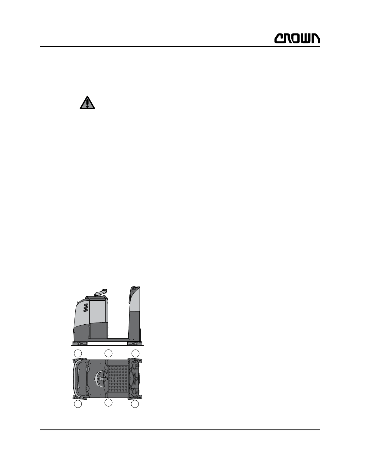
Lifting the truck with a crane
1. Remove the battery
2. Attach chains and hooks (2) to the cutouts in the
floorboard in front of the battery compartment (see
Fig.TC465).
3. Push a thin board on either side between the truck
and the chain.
4. Attach lifting slings around the tow hitch (1) (see
Fig.TC465).
Lifting the truck with a forklift truck
1. Remove the battery
2. Position the forks (1) of the truck that is doing the
lifting under the chassis of the lift truck (see
Fig. TC462).
TC465
TC462
2
1
1
1
LUBRICATION & ADJUSTMENT
Lifting and Jacking up the Truck
14
TC 3000
3. Attach the truck securely onto the forks (1) of the
truck doing the lifting (e.g. with a tensioning belt).
Jacking up the Truck
WARNING
Truck tipovers and incorrect handling of the
equipment can result in fatal injuries.
• Make sure the jack has sufficient capacity.
• Always support a raised truck with wooden blocks
or other suitable equipment to relieve the jack.
• Never place your hands or other parts of your body
under the truck before it has been supported.
Information on the capacity required can be found on
the truck data plate under “Truck Weight Less Battery”
and “Battery Weight”.
1. Place the jack in the centre of the left hand side of
the skirt (1, Fig. TC463) and raise the truck a
maximum of 20 mm.
2. Place hard wooden blocks (2) under the front and
rear ends of the chassis and lower the truck onto
them.
3. Place the jack in the centre of the right hand side
of the skirt (3) and raise the truck a maximum of
20 mm.
4. Place hard wooden blocks (4) underneath and
lower the truck.
TC463
1
3
4
4
2
2

LUBRICATION & ADJUSTMENT
Towing the Truck
15
TC 3000
Towing the Truck
WARNING
Truck tipovers and falling loads can cause death!
• Make sure the towing truck has sufficient capacity.
Information on the capacity required can be found on
the truck data plate under “Truck Weight Less Battery”
and “Battery Weight”.
NOTE
Risk of damage to the drive system!
As the drive wheel is braked on de-energised trucks,
the truck must be raised sufficiently when being towed
to prevent the drive wheel from contacting the ground.
1. Remove the battery.
2. Place the forks (1) of the towing tru ck un d er nea th
the lift truck (see Fig. TC464).
3. Raise the truck (approx. 20 mm) until the drive
wheel has been lifted off the ground.
4. Pull the truck slowly and only in a forward direc-
tion (as indicated by the arrow in Fig. TC464).
TC464
1
1

LUBRICATION & ADJUSTMENT
Taking the Truck out of Service
16
TC 3000
Taking the Truck out of Service
You must carry out the following tasks if you are withdrawing the truck from service for more than 3 months:
1. Disconnect the battery.
2. De-commission the battery in accordance with the
manufacturer‘s instructions.
3. Clean and then lubricate the truck.
NOTE
Note the following when cleaning the truck:
• Do not use pressure jets and/or solvents on the
truck.
• Do not use metal brushes.
• Do not wet-clean the electrical system.
• Do not use flammable cleaning agents.
• Take measures to protect the environment.
4. If possible store the truck in a dry room with as
constant a temperature and air humidity as
possible.
Do not park the truck outdoors or in a humid
environment.
5. If the truck has to be stored in hostile conditions
(e.g. saline atmosphere) treat the surface of the
truck with a suitable preservative to prevent
corrosion.
6. If the truck has to be stored in excessively dusty
conditions, cover it with a permeable material and
not plastic sheets as these can allow condensation
water to form.
7. Jack up the truck (see page 15), as otherwise the
constant pressure can cause the wheels to flatten.
Testing Re-Commissioned Trucks
Trucks that have been out of service for a long period
of time must be checked at regular intervals. T o do this,
proceed as follows:
1. Connect the battery and test the truck's functions.
2. Check the gear unit for leaks.
3. Check any anti-corrosion film that may have been
added and replace if necessary.
4. Disconnect the battery.
Restoring the Truck to Service
To restore the truck to service, proceed as follows:
1. Remove the anti-corrosion film.
2. Jack up the truck, remove the wooden blocks and
lower the truck.
3. Charge the battery or install a charged batt er y.
4. Connect the battery.
5. Carry out the daily safety inspection.

LUBRICATION & ADJUSTMENT
Recommended Lubricants and Accessories
17
TC 3000
Recommended Lubricants and
Accessories
The tables show typical lubricants used by Crown itself
in its facilities. However, you can use any lubricants
provided they meet the same technical criteria.
Cold Store Trucks
Special hydraulic oil, lubrication oil and grease must be
used for cold store trucks operating in low temperature
conditions (see table).
An anti-corrosion fluid (Crown no. 805236-004) must
be applied to all screws, washers, nuts, pins, retaining
rings etc. Carefully protect all electrical connections
and components against corrosion. For detailed information, refer to the Electrical System chapter.
Service intervals (see page 19) must be adapted to the
conditions of use.
Type Lubricant Type Product Manufacturer Crown
Part Number
A
Transmission oil Hyp 85W90 Aral
053002-004
GX-D 85W90 Esso
Mobilube HD85W90 Mobil
Spirax MB90 Shell
AA
Low temperature transmission oil
Mobil SHC 624 Mobil
053002-009
B
Grease (Multi-Purpose) Aralube HLP2 Aral
053002-001
LM Grease Castrol
Regulus A2 Century
Beacon EP2 Esso
EP2 Maxol
Mobiluxe EP2 Mobil
Retinax LX Shell
ALGWMI SKF
Renolit MP Fuchs
BB
Low temperature grease Aralube SKL2 Aral
053002-005Unirex Lotemp EP Mobil
Duraplex EP2 Fuchs
G
Lubrication oil Essolube HDX+40 Esso
053002-007Kowal M 40 Aral
Delvac 1240 Mobil
GG
Low temperature lubrication
oil
Mobil SHC 626 Mobil
053002-008
M
Special grease
Molycote
®
BR-2 Plus
Dow Corning
-----------------

LUBRICATION & ADJUSTMENT
Recommended Lubricants and Accessories
18
TC 3000
Lubricants Product Application Crown Part No.
Anti-corrosive agent Tectyl Corrosion inhibitor for cold store
trucks
805236-004
Rubber & Vinyl Dressing
Commercial Rubber Components, Plastic
Panels
-------------

LUBRICATION & ADJUSTMENT
Planned Maintenance
19
TC 3000
Planned Maintenance
The following inspection and maintenance schedule
assumes single-shift operation under normal conditions.
The maintenance intervals must however always be
adapted to the prevailing operating conditions. In dusty
or otherwise extreme operating conditions including
cold store application, the maintenance intervals specified must be reduced. Exact details should be discussed with a Crown service engineer.
Routinely check for wear, corrosion, damage, and test
component operation and safety when carrying out
maintenance work. If in doubt, replace components.
Planned maintenance must be performed either after a
certain number of service hours or a certain period of
time (whichever is reached first).
Guide to abbreviations:
M Months
h Service hours
X Perform on standard trucks
C Perform on cold store trucks
X/C Perform on standard and cold store trucks
12 M 24 M 36 M
Position Component Lubri-
cant
Action 500 h 1000 h 5000 h
I-1 Truck, general Clean truck if necessary.
NOTE
Note the following when cleaning the
truck:
• Do not use pressure jets and/or
solvents on the truck.
• Do not use metal brushes.
• Do not wet-clean the electrical
system.
• Do not use flammable cleaning
agents.
• Note the environmental safety
guidelines.
X/C
I-2
Labels, decals
(a)
Check that labels and decals are legible.
Replace any illegible or severely damaged decals.
X/C X
I-3 Handles*
Backrest grab bar*
Work Assist ™*
Ensure it is fitted securely and check
for damage. X/C
I-4 Emergency
Disconnect
(b)
Test Emergency Disconnect power
switch.
X/C
I-5
Steering
(b)
Check operation.
X/C
I-6
Travel functions
(b)
Drive the truck in both directions.
X/C

LUBRICATION & ADJUSTMENT
Planned Maintenance
20
TC 3000
I-7
Brake
(b)
Test by changing the travel direction
with the travel switch.
Check brake switch.
X/C
I-8 Hitch Position
Control™
(b)
Test in both directions.
X/C
I-9 Load wheels and
castors
Check bearing play.
Check tyres for wear.
X/C
I-10 Drive wheel Check wheel nut torque (130 Nm).
NOTE
On new trucks or after removing/assembling the drive wheel, torque the
wheel nuts after 100 h to 130 Nm.
Check tyres for wear.
X/C
I-11 Drive motor Torque drive motor mounting screws
to 16 Nm.
X/C
Check that power cable connections
on the drive motor are secure.
Torques:
Torque the bottom nut to 7.5 Nm.
Torque the top nut to 2.5 Nm.
X/C
I-12 Drive transmission
unit
Torque drive transmission unit mounting screws to 70 - 75 Nm.
X/C
I-13 Battery connector Check connector housing, contact
springs and cables. Clean contacts.
X/C
I-14 Electrical system Check insulation of all accessible
wires for damage.
Make sure switches and connections
are fitted securely and check for damage.
X/C
L-15 Battery cover B/BB Lubricat e hin ge s an d lock. X/C
I-16 Main contactor Clean main contactor contacts and
check for wear.
X/C
I-17 Traction controller Torque the traction controller mount-
ing screws to 8 - 10 Nm.
X/C
Check the power cable connections
on the traction controller are secure.
Nut torque: 13 - 15 Nm
X/C
Check and analyse error log. X/C
12 M 24 M 36 M
Position Component Lubri-
cant
Action 500 h 1000 h 5000 h
 Loading...