

Crown SWAN CAM Installation Instructions Manual
INSTALLATION INSTRUCTIONS
S W A N C A M
QUAD ELEMENT PIR & MONO/COLOUR CAMERA MOTION DETECTOR With PET IMMUNITY
PRODUCT FEATURES
Video sensing device
• High sensitivity and high-resolution board
camera.
• Electronic shutter control.
Audio sensing device
• Omnidirectional response.
• High sensitivity.
• AGC
• Quad (four element) PYRO sensor and hard
lens for outstanding detection performance and
elimination of false alarms.
• ASIC based electronics with movement speed
spectrum analysis.
• User-friendly installation with swivel bracket.
• BI directional temperature compensation.
• Environmental immunity.
• Pet immunity up to 25Kg. Pet active bellow 1m.
• Height installation calibrations free from 1.8m to
2.4m.
• Wide range operating voltage.
• High reliability and trouble free operation.
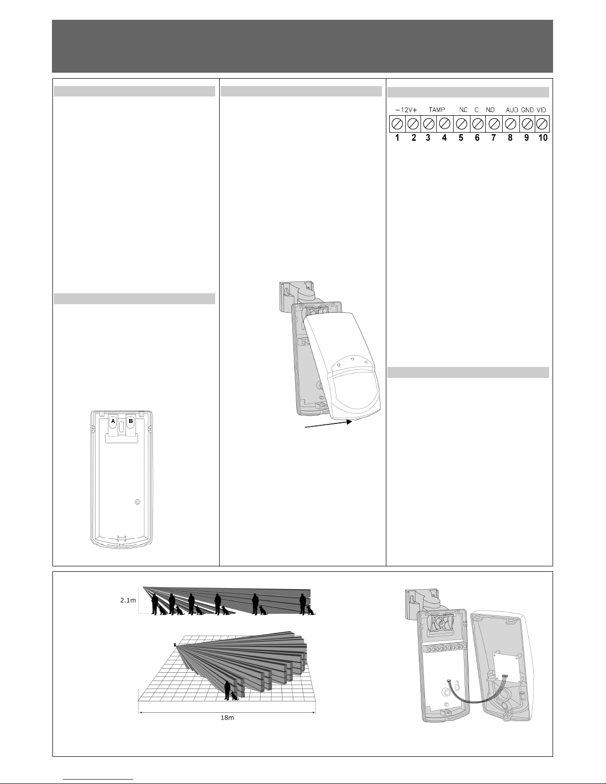
SELECT MOUNTING LOCATION
Choose a location most likely to intercept an intruder.
(Our recommendation is a corner installation). See
detection pattern fig.3. The quad-element high quality
sensor detects motion crossing the beam; it is slightly
less sensitive detecting motion toward the detector.
The SWAN CAM performs best when provided with a
constant and stable environment and background.
AVOID THE FOLLOWING LOCATIONS
• Facing direct sunlight.
• Facing areas that may change temperature
rapidly.
• Areas where there are air ducts or substantial
airflows.
Fig.1
DETECTOR INSTALLATION
The detector can either be wall, corner or ceiling
mounted by using special bracket base for the bracket
mounting.
Refer to bracket description. (See fig. 6).
1. To remove the front cover, unscrew the holding screw
and gently raise the front cover. (See fig.2).
2. Insert wire through the bracket and holes “A” and
“B”. (See fig.1)
3. Mount the bracket base to the wall or to the ceiling
with the suitable adaptor. Hold the detector base in
front of the protected area and tighten the bracket
screw.
4. Insert the wires through the bracket and connect the
wires to the terminal block.
5. Replace the cover by inserting it back in the
appropriate closing pins and screw in the holding
screw.
Fig.2
DETECTOR CONNECTION
Terminal 1 - Marked “ - ” (GND)
Connect to the negative supply voltage output or ground
Terminal 2 - Marked “ + ” (+12V)
Connect to a positive supply voltage output of 8.2 16Vdc source (usually from the alarm control unit)
Terminals 3 & 4 - Marked “ TAMP ”
If a Tamper function is required connect these terminals
to a 24-hour normally closed protective zone in the
control unit. If the front cover of the detector is opened,
an immediate alarm signal will be sent to the control
unit.
Terminals 5,6 & 7 - Marked “ N.C, C & N.O ”
These are the output relay contacts of the detector.
Connect to a normally closed or normally opened zone
in the control panel.
Terminals 8 & 9 - Marked “ AUD ”& “GND”
This is the audio signal output. These two terminals
should be connected to an audio input.
Terminals 9 & 10 - Marked “ GND ”& “VID”
This is the video signal output. These two terminals
should be connected to video input.
TESTING THE DETECTOR
Wait one minute after applying 12Vdc power - warm up
time.
Conduct testing with the protected area cleared of all
people.
Walk test
1. Remove front cover.
2. Set LED to ON position.
3. Reassemble the front cover.
4. Start walking slowly across the detection zone.
5. Observe that the LED lights whenever motion is
detected.
6. Allow 5 sec. between each test for the detector to
stabilize.
7. After the walk test is completed, you can set the
LED to OFF position.
NOTE:
Walk tests should be conducted, at least once a year, to
confirm proper operation and coverage of the detector.
Fig.3
Fig.4
7101574_B - 1 -
Unscrew the holding
screw and open base
INSTALLATION INSTRUCTIONS
S W A N C A M
QUAD ELEMENT PIR & MONO/COLOUR CAMERA MOTION DETECTOR With PET IMMUNITY
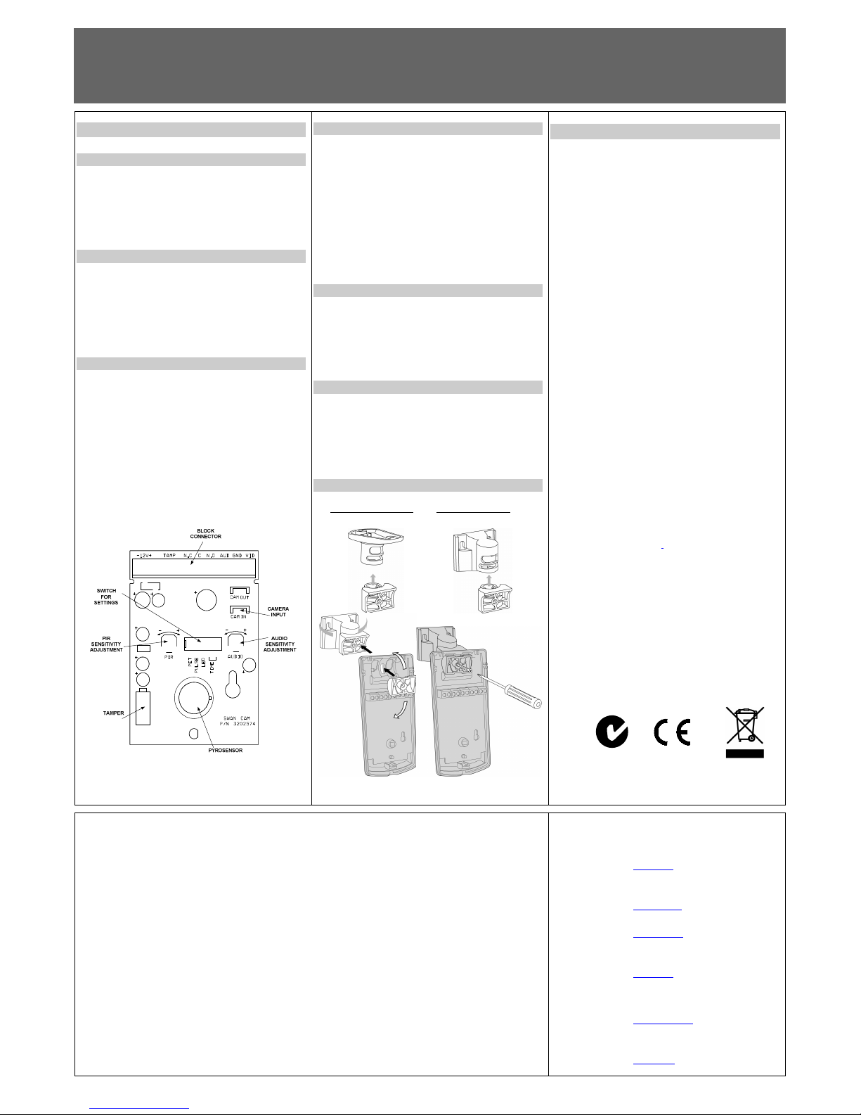
SETTING UP THE DETECTOR
PET IMMUNITY SETTING
Switch 1 of dipswitch DIP5, use for setting the PET
Immune function - Up to 15Kg or 25Kg, depending on
the pet size.
Position Up - ON - Immune to pet weighting up to 15 kg
Position Down - OFF - Immune to a pet weighting up to
25 kg
PIR PULSE COUNT ADJUSTMENT
Switch 2 of dipswitch DIP5, use for setting the PULSE
count function in order to provide PIR sensitivity control
according to the environment.
Position Up – ON – High sensitivity
For stable environments.
Position Down – OFF – Low sensitivity
For harsh environments.
LED SETTING
Switch 3 of dipswitch DIP5, use for setting - LED
Enable / Disable.
Position Up - ON – LED ENABLE, The LED will
activate when the detector is in alarm condition.
Position Down – OFF - LED DISABLE, The LED is
disabled.
Note: The LED Switch does not affect the operation of
the relay.
When an intrusion is detected, the LED will activate
and the alarm relay will switch into alarm condition for
2 sec.
Fig.5
N.O RELAY - TIME DELAY SETTING
Switches 4 & 5 of dipswitch DIP-5 use for setting the
time delay of the N.O. Relay terminals 6 & 7.
There are four options.
Switch Switch
4 5 N.O. RELAY TIME DELAY
ON ON 2 Sec. Contact closed
ON OFF 15 Sec. Contact closed
OFF ON 60 Sec. Contact closed
OFF OFF 240 Sec. Contact closed
The N.C. Relay (Terminals 5 &6) opens for 1.8 – 2 sec.
when an alarm occurs.
PIR SENSITIVITY ADJUSTMENT
Use the Potentiometer marked “PIR” to adjust the
detection sensitivity between 15% and 100% according
to walk test in the protected area.
(Factory setting to 57%).
Rotate the potentiometer clockwise to increase range,
counter-clockwise to decrease range.
AUDIO SENSITIVITY ADJUSTMENT
Use the potentiometer “AUDIO” to adjust the audio
sensitivity.
Rotate the potentiometer clockwise to increase
sensitivity.
Rotate the potentiometer counter-clockwise to
decrease sensitivity.
BRACKET INSTALLATION OPTIONS
Ceiling bracket base Wall bracket base
Fig.6
TECHNICAL SPECIFICATION
Camera Type B&W: CCIR or EIA
COLOR: PAL or NTSC
Picture Elements 290K (PAL; CCIR) 250K
(NTSC;EIA)
Resolution 420 TV lines (PAL; NTSC)
380 TV lines (CCIR; EIA)
Sensitivity 0.5Lux - F2.0 (NTSC; PAL)
0.5Lux - F1.2 (EIA; CCIR)
S/N Ratio Better then 48 dB
Electronic Shutter
Time 1/60 – 1/100,000 sec
(NTSC; EIA)
1/50 – 1/100,000 sec
(PAL; CCIR)
Video Output 1V p-p 75Ω
Detection Method Quad (four) element PIR
Power Input 8.2 to 16 Vdc
Current Draw Mono: 115 mA
Colour: 150 mA
Temperature
Compensation YES
Alarm Period 2 +/- 1 sec
Alarm Output N.C 28Vdc 0.1 A with
10Ohm series protection
resistors
Tamper Switch N.C 28Vdc 0.1A with
10 Ohm series protection
resistor - open when cover
is removed
Warm Up Period 1 min
LED Indicator Red LED is ON during alarm
Dimensions 123mm x 61mm x 38mm
Weight 135 gr.
CROW ELECTRONIC ENGINEERING LTD. ("Crow") - WARRANTY POLICY CERTIFICATE
This Warranty Certificate is given in favor of the purchaser (hereunder the "Purchaser") purchasing the products directly from Crow or from its authorized distributor.
Crow warrants these products to be free from defects in materials and workmanship under normal use and service for a period of 24 months from the last day of the week and
year whose numbers are printed on the printed circuit board inside these products (hereunder the "Warranty Period").
Subject to the provisions of this Warranty Certificate, during the Warranty Period, Crow under takes, at its sole discretion and subject to Crow's procedures, as such procedures
are form time to time, to repair or replace, free of charge for materials and/or labor, products proved to be defective in materials or workmanship under normal use and s ervice.
Repaired products shall be warranted for the remainder of the original Warranty Period.
All transportation costs and in-transit risk of loss or damage related, directly or indirectly, to pr oducts returned to Crow for repair or replacement shall be borne solely by the
Purchaser.
Crow's warranty under this Warranty Certificate does not cover products that is defective (or shall become defective) due to: (a) alteration of the products (or any part thereof) by
anyone other than Crow; (b) accident, abuse, negligence, or improper maintenance; (c) failure caused by a produ ct which Crow did not provide; (d) failure caused by software or
hardware which Crow did not provide; (e) use or storage other than in accordance with Crow’s specified operating and storage instructions.
There are no warranties, expressed or implied, of merchantability or fitness of the products for a particular purpose or otherwise, which extend beyond the description on the face
hereof.
This limited Warranty Certificate is the Purchas er's sole and exclusive remedy against Crow and Crow's sole and exclusive liability toward the Purchaser in connection with the
products, including without limitation - for defects or malfunctions of the products. This Warranty Certificate replaces all other warranties and liabilities, whether oral, written, (nonmandatory) statutory, contractual, in tort or otherwise.
In no case shall Crow be liable to anyone for any consequential or incidental damages (inclusive of loss of profit, and whether occasioned by negligence of the Crow or any third
party on its behalf) for breach of this or any other warranty, expressed or implied, or upon any other basis of liability whatsoever. Crow does not r epresent that these products
can not be compromised or circumvented; that these products will prevent any person injury or property loss or damage by burglary, robbery, fire or otherwise; or that these
products will in all cases provide adequate warning or protection.
Purchaser understands that a properly installed and maintained product may in some cases reduce the risk of bur glary, fire, robbery or other events occurring without providing
an alarm, but it is not insurance or a guarantee that such will not occur or that there will be no personal injury or property loss or damage as a result.
Consequently, Crow shall have no liability for any personal injury; property damage or any other loss based on claim that these products failed to give any warning.
If Crow is held liable, whether directly or indirectly, for any loss or damage with regards to these products, regardless of cause or origin, Crow’s maximum liability shall not in any
case exceed the purchase price of these products, which shall be the complete and exclusive remedy against Crow.
P/N 7101574 REV. B Y.S - A.Y.
CROW ELECTRONIC ENGINEERING LTD.
ISRAEL: Crow Electronic Engineering Ltd.
12 Kineret St. Airport City
P.O. Box 293 Ben Gurion Airport , 70100
Tel: 972-3-9726000
Fax: 972-3-9726001
E-mail: support@crow.co.il
USA: 2160 North Central Road,
Fort Lee, N.J. 07024
Tel: 1-800-GET CROW
or (201) 944 0005
Fax: (201) 944 1199
E-mail: support@crowelec.com
AUSTRALIA: 429 Nepean HWY Brighton East Vic 3187
Tel: 61-3-9596 7222
Fax: 61-3-9596 0888
E-mail: crow@crowaust.com.au
POLAND: VIDICON SP. ZO. O.
15 Povazkowska St.
01 – 797 Warsaw Poland
Tel: 48 22 562 3000
Fax: 48 22 562 3030
E-mail: vidicon@vidicon.pl
LATIN AMERICA: CROW LATIN AMERICA
5753 NW 151ST.Street
MIAMI LAKES,
FL 33014 – USA
Tel: +1-305-823-8700
Fax: +1-305-823-8711
E-mail:
sales@crowlatinamerica.com
ITALY: DEATRONIC
VIA Giulianello 4/14
00178 ROMA, ITALY
Tel: +39-0676-12912
Fax: +39-0676-12601
E-mail: info@deatronic.com
These instructions supersede all previous issues in circulation prior to October 2005.
7101574_B - 2 -
N345
 Loading...