

Page 1
Operation Manual
Studio Reference Series
®
Studio Reference I
®
Studio Reference II
Obtaining Other Language Versions:
local Crown Distributor. If you need assistance locating your local distributor, please contact Crown at 574-294-8000.
This manual does not include all of the details of design, production, or variations of the equipment. Nor does it cover every possible
situation which may arise during installation, operation or maintenance.
The information provided in this manual was deemed accurate as of the publication date. However, updates to this information may have
occurred. To obtain the latest version of this manual, please visit the Crown website at www.crownaudio.com.
Trademark Notice:
and IQ are registered trademarks of Crown International. Other trademarks are the property of their respective owners.
©2003 by Crown Audio Inc., P.O. Box 1000, Elkhart, Indiana 46515-1000 U.S.A. Telephone: 574-294-8000
Studio Reference, SmartAmp, Grounded Bridge, PIP2 and PIP are trademarks and Crown, Amcron, IOC, ODEP,
To obtain information in another language about the use of this product, please contact your
Some models may be exported under the name Amcron.
®
132176-3
5/03
Page 2
Important Safety
Instructions
Studio Reference I & II Professional Studio Amplifiers
1) Read these instructions.
2) Keep these instructions.
3) Heed all warnings.
4) Follow all instructions.
5) Do not use this apparatus near water.
6) Clean only with a dry cloth.
7) Do not block any ventilation openings. Install
in accordance with the manufacturer’s instructions.
8) Do not install near any heat sources such as
radiators, heat registers, stoves, or other
apparatus that produce heat.
9) Do not defeat the safety purpose of the polarized or grounding-type plug. A polarized plug
has two blades with one wider than the other.
A grounding-type plug has two blades and a
third grounding prong. The wide blade or the
third prong is provided for your safety. If the
provided plug does not fit into your outlet,
consult an electrician for replacement of the
obsolete outlet.
10) Protect the power cord from being walked on
or pinched, particularly at plugs, convenience
receptacles, and the point where they exit from
the apparatus.
11) Only use attachments/accessories specified by the manufacturer.
12) Use only with a cart, stand, bracket, or table
specified by the manufacturer, or sold with the
apparatus. When a cart is used, use caution
when moving the cart/apparatus combination
to avoid injury from tip-over.
13) Unplug this apparatus during lightning storms or when unused for long periods of time.
14) Refer all servicing to qualified service personnel. Servicing is required when the apparatus
has been damaged in any way, such as powersupply cord or plug is damaged, liquid has
been spilled or objects have fallen into the
apparatus, the apparatus has been exposed to
rain or moisture, does not operate normally,
or has been dropped.
15) To reduce the risk of fire or electric shock, do not expose this apparatus to rain or moisture.
TO PREVENT ELECTRIC SHOCK DO NOT REMOVE
TOP OR BOTTOM COVERS. NO USER SERVICEABLE PARTS INSIDE. REFER SERVICING TO
QUALIFIED SERVICE PERSONNEL.
À PRÉVENIR LE CHOC ÉLECTRIQUE N’ENLEVEZ
PAS LES COUVERCLES. IL N’Y A PAS DES PARTIES SERVICEABLE À L’INTÉRIEUR. TOUS REPARATIONS DOIT ETRE FAIRE PAR PERSONNEL
QUALIFIÉ SEULMENT.
IMPORTANT
Studio Reference Series amplifiers require Class 2
output wiring.
MAGNETIC FIELD
CAUTION! Do not locate sensitive high-gain equipment such as preamplifiers or tape decks directly
above or below the unit. Because this amplifier has
a high power density, it has a strong magnetic field
which can induce hum into unshielded devices that
are located nearby. The field is strongest just above
and below the unit.
If an equipment rack is used, we recommend locating the amplifier(s) in the bottom of the rack and the
preamplifier or other sensitive equipment at the top.
WATCH FOR THESE SYMBOLS:
The lightning bolt triangle is used to alert the user
to the risk of electric shock.
The exclamation point triangle is used to alert the
user to important operating or maintenance instructions.
This device complies with part 15 of the FCC rules. Operation is subject to the following
FCC COMPLIANCE NOTICE
two conditions: (1) This device may not cause harmful interference, and (2) this device
must accept any interference received, including interference that may cause undesired
operation.
CAUTION: Changes or modifications not expressly approved by the party responsible for
compliance could void the user’s authority to operate the equipment.
NOTE: This equipment has been tested and found to comply with the limits for a Class B
digital device, pursuant to part 15 of the FCC Rules. These limits are designed to provide
reasonable protection against harmful interference in a residential installation. This equipment generates, uses, and can radiate radio frequency energy and, if not installed and used
in accordance with the operation manual, may cause harmful interference to radio communications. However, there is no guarantee that interference will not occur in a particular
installation. If this equipment does cause harmful interference to radio or television reception, which can be determined by turning the equipment off and on, the user is encouraged
to try to correct the interference by one or more of the following measures:
• Reorient or relocate the receiving antenna.
• Increase the separation between the equipment and receiver.
• Connect the equipment into an outlet on a circuit different from that to which the receiver
is connected.
• Consult the dealer or an experienced radio/TV technician for help.
page 2
Operation Manual
Page 3
Studio Reference I & II Professional Studio Amplifiers
Crown International, Inc.
Issued By: Crown International, Inc.
1718 W. Mishawaka Road
Elkhart, Indiana 46517 U.S.A.
European Representative's Name and Address:
Nick Owen
19 Clos Nant Coslech
Pontprennau
Cardiff
CF23 8ND United Kingdom
Equipment Type: Commercial Audio Power Amplifiers
Family Name: Studio Reference
Model Names: Studio Reference I, Studio Reference II
EMC Standards:
EN 55103-1:1995 Electromagnetic Compatibility - Product Family Standard for Audio, Video, Audio-Visual and Entertainment Lighting Control Apparatus for Professional Use, Part 1: Emissions
EN 55103-1:1995 Magnetic Field Emissions-Annex A @ 10 cm and 1 M
EN 61000-3-2:1995+A14:2000 Limits for Harmonic Current Emissions (equipment input current ≤16A per phase)
EN 61000-3-3:1995 Limitation of Voltage Fluctuations and Flicker in Low-Voltage Supply Systems Rated Current ≤16A
EN 55022:1992 + A1: 1995 & A2:1997 Limits and Methods of Measurement of Radio Disturbance Characteristics of ITE: Radiated, Class B Limits; Conducted, Class B
EN 55103-2:1996 Electromagnetic Compatibility - Product Family Standard for Audio, Video, Audio-Visual and Entertainment Lighting Control Apparatus for Professional Use, Part 2: Immunity
EN 61000-4-2:1995 Electrostatic Discharge Immunity (Environment E2-Criteria B, 4k V Contact, 8k V Air Discharge)
EN 61000-4-3:1996 Radiated, Radio-Frequency, Electromagnetic Immunity (Environment E2, criteria A)
EN 61000-4-4:1995 Electrical Fast Transient/Burst Immunity (Criteria B)
EN 61000-4-5:1995 Surge Immunity (Criteria B)
EN 61000-4-6:1996 Immunity to Conducted Disturbances Induced by Radio-Frequency Fields (Criteria A)
EN 61000-4-11:1994 Voltage Dips, Short Interruptions and Voltage Variation
Safety Standard:
EN 60065: 1998 Safety Requirements - Audio Video and Similar Electronic Apparatus
I certify that the product identified above conforms to the requirements of the EMC Council Directive 89/336/EEC as amended by 92/31/EEC, and the Low Voltage Directive 73/23/EES as amended by 93/68/EEC.
Signed
Larry Coburn
Title: Senior Vice President of Manufacturing
DECLARATION of CONFORMITY
Date of Issue: January 1, 2000
Sue Whitfield
574-294-8289
[email protected]
Operation Manual
DUE TO LINE CURRENT HARMONICS, WE RECOMMEND THAT YOU CONTACT YOUR SUPPLY AUTHORITY BEFORE CONNECTION.
page 3
Page 4

Table of Contents
Studio Reference I & II Professional Studio Amplifiers
Important Safety Instructions .......................................................2
Declaration of Conformity ............................................................3
1 Welcome .................................................... 5
1.1 Features ...........................................................................5
1.2 How to Use This Manual ..................................................6
2 Setup ......................................................... 7
2.1 Unpack Your Amplifier ....................................................7
2.2 Install Your Amplifier ......................................................7
2.3 Ensure Proper Cooling ...................................................7
2.4 Choose Input Wire and Connectors ................................8
2.5 Choose Output Wire and Connectors ..............................8
2.6 Wire Your System ...........................................................9
2.6.1 Stereo Mode ..........................................................9
2.6.2 Bridge-Mono Mode ...............................................10
2.6.3 Parallel-Mono Mode...............................................11
2.7 Connect to AC Mains ......................................................12
2.8 Startup Procedure ...........................................................12
3 Operation ...................................................13
3.1 Precautions .....................................................................13
3.2 Front Panel Controls and Indicators ...............................15
3.3 Back Panel Controls and Connectors...............................17
4 Advanced Features and Options .........................18
4.1 Indicators .......................................................................18
4.2 Protection Systems ........................................................18
4.2.1 ODEP......................................................................18
4.2.2 Standby Mode........................................................19
4.2.3 Transformer Thermal Protection .............................19
4.2.4 Circuit Breaker ....................................................... 19
4.3 Filter Cleaning ................................................................ 19
4.4 Controls ......................................................................... 20
4.4.1 Level Controls ....................................................... 20
4.4.2 Meter Switches ......................................................20
4.4.3 Ground Lift Switch .................................................21
4.4.4 Input Sensitivity Switch .........................................21
4.5 PIP Modules ...................................................................21
5 Principles of Operation .................................... 22
5.1 Overview ........................................................................22
5.2 Circuit Theory ................................................................ 23
5.2.1 Stereo Operation .................................................... 23
5.2.2 Bridge-Mono Operation .........................................23
5.2.3 Parallel-Mono Operation .......................................23
6 Troubleshooting ............................................ 24
7 Specifications ..............................................25
7.1 Mininum Guaranteed Power Specifications .................... 27
7.2 Maximum Power Specifications ..................................... 29
8. AC Power Draw & Thermal Dissipation ................ 32
9 Service ... .............................................................................. 34
9.1 Worldwide Service .......................................................... 34
9.2 US and Canada Service .................................................. 34
9.2.1 Service at a US or Canada Service Center ............. 34
9.2.2 Factory Service ......................................................34
9.2.3 Factory Service Shipping Instructions ................... 34
10 Warranty ...................................................35
Crown Factory Service Information Form ...................................37
page 4
Operation Manual
Page 5
Studio Reference I & II Professional Studio Amplifiers
®
1 Welcome
The stunning realism you will experience when
listening to a Crown
fier will redefine your expectations. The evolution of this studio standard ushers in a new era
of powerful, ultraquiet amplifiers capable of
faithfully reproducing the most demanding of
signals. This kind of sonic integrity does not
happen accidentally. It demands the leadership
and technical excellence for which Crown has
long been known.
With the best transfer function in the industry,
ultra-high dynamic range and extraordinary
damping factor, your Studio Reference amplifier
comes closer to the ideal “straight wire with
gain” than any other amplifier. As you listen, it
will become apparent—the amplifier’s low-frequency transient response is the standard by
which all others must be judged.
We have taken great care at every step in the creation of your amplifier—from the selection of its
components to the routing of each wire. It is our
goal to provide you with total satisfaction. This is
one reason why we have spent considerable
®
Studio Reference™ ampli-
effort in providing you with the most complete
Reference Manual in the business. Please read it
carefully—especially the instructions, warnings
and cautions. It will help you successfully install
and use your new amplifier. Be sure to read Sections 2.5.2 and 2.5.3 if you plan to use one of the
amplifier’s two mono modes.
1.1 Features
• Accurate Studio Reference amplifiers integrate
several cutting edge technologies that make
them the most accurate reference amplifiers
available. For example, in Stereo mode each
channel can actually be treated as a separate
amplifier because of its separate high-voltage
power supplies and ultra-low crosstalk. Here are
some of its many impressive features:
• Crown’s unconventional Grounded Bridge™
circuitry delivers incredible voltage swings without using stressful output transistor configurations like other more traditional amplifiers. This
results in significantly lower distortion and
superior reliability.
• Patented ODEP
®
(Output Device Emulation
Protection) circuitry detects and compensates
for overheating and overload to keep the amplifier working when others would fail.
®
• IOC
(Input/Output Comparator) circuitry
immediately alerts you of any distortion that
exceeds 0.05% to provide dynamic proof of distortion-free performance.
• PIP™ (Programmable Input Processor) connector accepts accessories that tailor your
amplifier to suit specific applications.
• Extremely wide dynamic range.
• Ultra-high damping factor delivers superior
loudspeaker motion control for the cleanest,
tightest bottom end you’ve ever felt—or heard.
• Super-low harmonic and intermodulation distortion give your amplifier the best transfer function in the business.
• Two mono modes (Bridge-Mono and ParallelMono) for driving a wide range of load impedances.
• Custom-designed, tape-wound, low-noise
toroidal supplies with extremely high power density.
• High-voltage headroom and high-current
headroom provide energy reserves that make it
easy to drive low-impedance loads and highly
reactive loads to full power.
• Full protection against shorted outputs, mismatched loads, general overheating, DC and
Operation Manual
page 5
Page 6

1 Welcome
Studio Reference I & II Professional Studio Amplifiers
high-frequency overloads. Full overvoltage and
internal fault protection.
• Indicators include Enable, ODEP, IOC, Signal
Presence and the Dynamic Range/Level meter.
• Balanced phone jacks and XLR connectors
are provided for input. Two pair of 5-way binding
posts per channel are provided for versatile output connection.
• Ground lift switch isolates the AC power and
phone jack audio grounds.
• Efficient heat sinks and a self-contained, ondemand, infinitely variable forced-air cooling
system prevents overheating and prolongs component life.
• Internal three-position input sensitivity switch
provides settings of 0.775 volts and 1.4 volts for
standard 1 kHz power, and 26 dB gain.
• Mounts in a standard 19 inch (48.3 cm)
equipment rack, or units can be stacked directly
on top of each other.
• Three year “No-Fault” full warranty completely protects your investment and guarantees
its specifications.
1.2 How to Use This Manual
This manual provides you with the necessary
information to safely and correctly setup and
operate your amplifier. It does not cover every
aspect of installation, setup or operation that
might occur under every condition. For additional information, please consult Crown’s
Amplifier Application Guide (available online at
www.crownaudio.com), Crown Technical Support, your system installer or retailer.
We strongly recommend you read all instructions, warnings and cautions contained in this
manual. Also, for your protection, please send in
your warranty registration card today. And save
your bill of sale — it’s your official proof of purchase.
page 6
Operation Manual
Page 7
Studio Reference I & II Professional Studio Amplifiers
2 Setup
Figure 2.1 Removing an
End Cap
2.1 Unpack Your Amplifier
Please unpack and inspect your amplifier for
any damage that may have occurred during
transit. If damage is found, notify the transportation company immediately. Only you can initiate a claim for shipping damage. Crown will
be happy to help as needed. Save the shipping
carton as evidence of damage for the shipper’s
inspection.
We also recommend that you save all packing
materials so you will have them if you ever
need to transport the unit. Never ship the
unit without the factory pack.
YOU WILL NEED (not supplied):
• Input wiring cables
• Output wiring cables
Rack for mounting amplifier (or a stable surface
for stacking)
WARNING: Before you start to set up
your amplifier, make sure you read and
observe the Important Safety Instructions found at the beginning of this
manual.
Before proceeding, make sure the meter
switches are set to your liking. The front panel
assembly must first be removed to changed
these switches, so it is easier to do before the
unit is mounted (see Section 4.4.2).
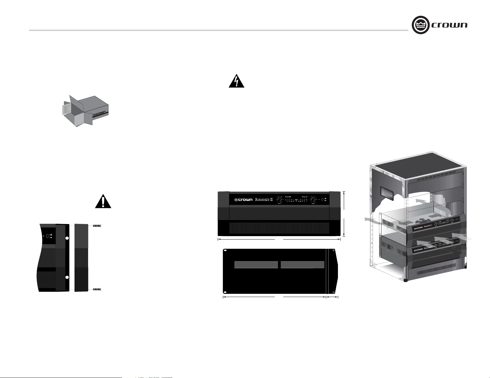
The rack ears are covered by two attractive end
caps which are held in place by phillips screws
(see Figure 2.1). To use the rack ears, remove
the screws and lift off the caps. With sufficient
side clearance, you can reinstall the end caps
once the amplifier is mounted in the rack.
2.2 Install Your Amplifier
CAUTION: Before you begin, make sure
your amplifier is disconnected from the
power source, with the power switch in
the “off” position and all level controls
turned completely down (counterclockwise).
Use a standard 19-inch (48.3 cm) equipment
rack (EIA RS-310B). See Figure 2.2 for amplifier dimensions.
You may also stack amps without using a
cabinet.
NOTE: When transporting, amplifiers should be
supported at both front and back.
®
FRONT VIEW
19 in
(48.3 cm)
SIDE VIEW
16 in
(40.6 cm)
(3.6 cm)
Figure 2.2
Dimensions
1.4 in
7 in
(17.3 cm)
2.3 Ensure Proper Cooling
When using an equipment rack, mount units
directly on top of each other. Close any open
spaces in rack with blank panels. DO NOT
block front, rear or side air vents. The side
walls of the rack should be a minimum of two
inches (5.1 cm) away from the amplifier sides,
and the back of the rack should be a minimum
of four inches (10.2 cm) from the amplifier back
panel.
Figure 2.3 illustrates standard amplifier airflow.
Figure 2.3 Airflow
Operation Manual
page 7
Page 8
2 Setup
2.4 Choose Input Wire and Connectors
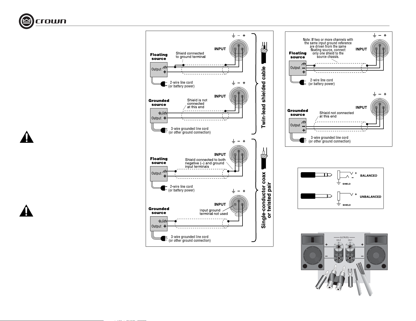
Crown recommends using pre-built or professionally wired, balanced line (two-conductor plus shield), 22-24 gauge cables and
connectors. Use either 3-pin male XLR connectors orTRS phone
plugs at the amplifier inputs.
Unbalanced lines may also be used but may result in noise over
long cable runs.
Connector pin assignments and wiring are shown in thes
Figures:
Figure 2.4: Unbalanced XLR
Figure 2.5: Balanced XLR
Figure 2.6: Balanced and unbalanced phone plugs.
NOTE: Custom wiring should only be performed by
qualified personnel.
2.5 Choose Output Wire and Connectors
Crown recommends using pre-built or professionally wired, highquality, two-conductor, heavy gauge speaker wire and connectors.
You may use banana plugs, spade lugs, or bare wire for your output connectors (Figure 2.7). To prevent the possibility of shortcircuits, wrap or otherwise insulate exposed loudspeaker cable
connectors.
NOTE: Binding post outputs on European models come
with safety plugs installed to prevent European powercord plugs from being inserted. The top & bottom entry
positions for these connectors should therefore be used
with European models.
Using the guidelines below, select the appropriate size of wire
based on the distance from amplifier to speaker.
Distance Wire Size
up to 25 ft. 16 AWG
26-40 ft. 14 AWG
41-60 ft. 12 AWG
61-100 ft. 10 AWG
101-150 ft. 8 AWG
151-250 ft. 6 AWG
CAUTION: Never use shielded cable for output wiring.
Studio Reference I & II Professional Studio Amplifiers
Figure 2.5 Balanced Input Wiring
Figure 2.6 Balanced and Unbalanced Phone Plugs
Figure 2.4 Unbalanced Input Wiring
Figure 2.7
Output Connector
Wiring
Note: Each output channel has two sets of
binding posts (not shown here) to make it
easier to connect multiple loudspeaker
cables to each channel.
page 8
Operation Manual
Page 9
Studio Reference I & II Professional Studio Amplifiers
2 Setup
2.6 Wire Your System
2.6.1 Stereo Mode
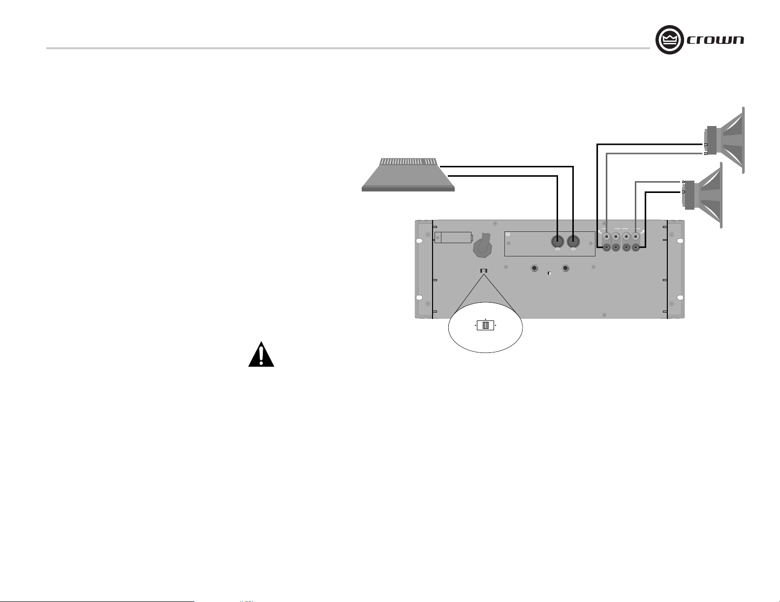
Typical input and output wiring is shown in
Figure 2.8.
Turn off the amplifier and set the
Stereo/Mono Switch to Stereo.
INPUTS: Connect input wiring for both channels.
NOTE: Crown provides a reference of wiring pin
assignments for commonly used connector
types in the Crown Amplifier Application Guide
available at www.crownaudio.com.
OUTPUTS: Each output channel has two sets of
binding posts to make it easier to connect multiple loudspeaker cables to each channel.
Maintain proper polarity (+/–) on output connectors.
Connect Channel 1 loudspeaker’s positive (+)
lead to Channel 1 positive (red) terminal of amp;
repeat for negative (–). Repeat Channel 2 wiring
as for Channel 1.
CAUTION: In Stereo mode, never tie an
amplifier’s outputs together directly, and
never parallel them with the output of
another amplifier. Such connections do not
result in increased output power, but may
activate the protection circuitry to prevent overheating.
CHANNEL 1
CHANNEL 2
MIXER
CH-2 CH-1
STUDIO REFERENCE
AMPLIFIER
STEREO
PARALLEL
MONO
CAUTION: TURN OFF AMPLIFIER
BEFORE CHANGING THIS SWITCH!
BRIDGE
MONO
FX
PUSHPUSH
STUDIO
Referen ce
CHANNEL 2
LOUDSPEAKER
CHANNEL 1
LOUDSPEAKER
–
+
+
–
Figure 2.8
Stereo Wiring
Operation Manual
page 9
Page 10
2 Setup
2.6.2 Bridge-Mono Mode
Bridge-Mono mode is used to drive loads with a
total impedance of 4 ohms or higher.
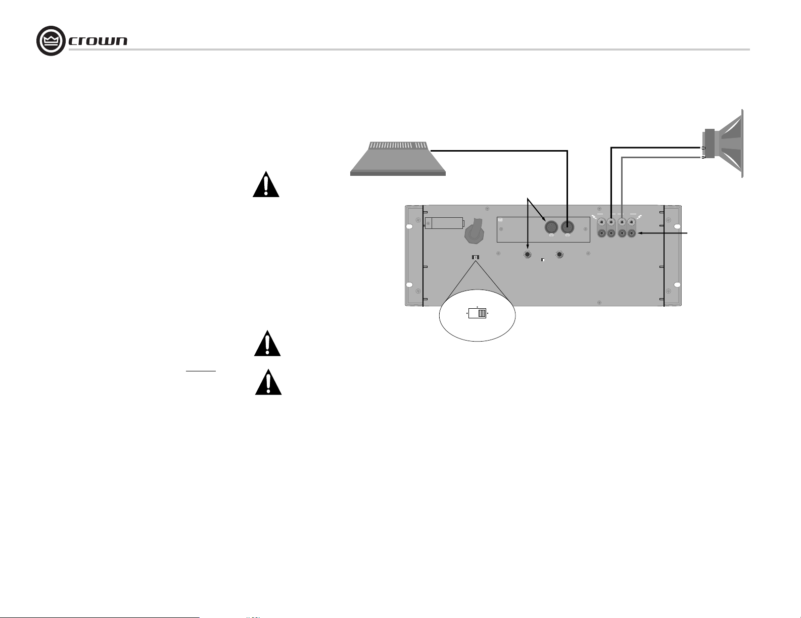
Typical input and output wiring is shown in
Figure 2.9.
Turn off the amplifier and set the
Stereo/Mono Switch to Bridge Mono.
INPUTS: Use only the Channel 1 input
connector.
NOTE: Crown provides a reference of wiring pin
assignments for commonly used connector
types in the Crown Amplifier Application Guide
available at www.crownaudio.
OUTPUTS: Connect the speaker across the red
binding post of each channel. Do not use the
black binding posts when the amp is being operated in Bridge-Mono mode.
The load MUST be balanced (neither side
shorted to ground).
NOTE: The Channel 2 level control MUST
be turned down (full CCW) when operating the amplifier in Bridge-Mono mode.
CAUTION: Connect only balanced
equipment (meters, switches, etc.) to the
Bridge-Mono output. Both sides of the
line must be isolated from the input
ground, or oscillations may occur.
MIXER
STUDIO REFERENCE
AMPLIFIER
STEREO
PARALLEL
MONO
CAUTION: TURN OFF AMPLIFIER
BEFORE CHANGING THIS SWITCH!
Studio Reference I & II Professional Studio Amplifiers
–
+
LOUDSPEAKER
DO NOT USE
THE BLACK
BINDING
POSTS.
BRIDGE
MONO
CHANNEL 1
FX
DO NOT USE
THE CHANNEL 2
INPUTS.
STUDIO
Referen ce
Bridge-Mono Wiring
CH-2 CH-1
PUSHPUSH
Figure 2.9
page 10
Operation Manual
Page 11
Studio Reference I & II Professional Studio Amplifiers
2 Setup
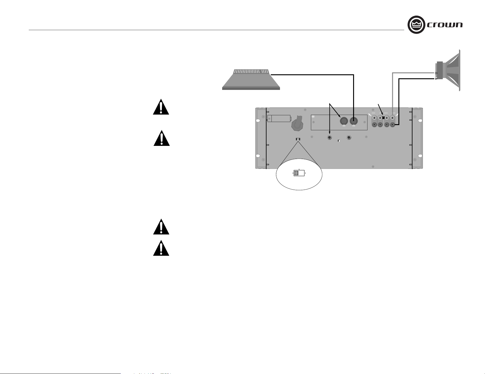
2.6.3 Parallel-Mono Mode
Parallel-Mono mode is used to drive loads with
a total impedance of less than 4 ohms.
Typical input and output wiring is shown in
Figure 2.10.
Turn off the amplifier and set the
Stereo/Mono Switch to Parallel-Mono.
Note: It is normal for the Channel 2 IOC
indicator to stay on in Parallel-Mono mode.
INPUTS: Use only the Channel 1 input
connector.
NOTE: Crown provides a reference of wiring pin
assignments for commonly used connector
types in the Crown Amplifier Application Guide
available at www.crownaudio.
OUTPUTS:
• Connect speaker positive (+) lead to
Channel 1 red (+) binding post.
• Connect speaker negative (–) lead to
Channel 2 black (–) binding post.
• Add a 14 gauge or larger jumper between the
Channel 1 and 2 red (+) binding posts.
NOTE: The Channel 2 level control MUST
be turned down (full CCW) when operating the amplifier in Parallel-Mono mode.
CAUTION: When Parallel-Mono wiring is
installed, do not attempt to operate in
Stereo or Bridge-Mono mode until the
wiring is removed (especially the jumper
wire). Failure to do so will lresult in high
distortion and excessive heating.
MIXER
STUDIO REFERENCE
AMPLIFIER
STEREO
PARALLEL
MONO
CAUTION: TURN OFF AMPLIFIER
BEFORE CHANGING THIS SWITCH!
CHANNEL 1
ADD A 14 GAUGE
JUMPER BETWEEN
THE CHANNEL 1
BINDING POSTS
PUSHPUSH
BRIDGE
MONO
FX
THE CHANNEL 2
INPUTS ARE
NOT USED
Referen ce
STUDIO
Figure 2.10 Parallel-Mono Wiring
OR LARGER
AND 2 RED (+)
CH-2 CH-1
+
–
LOUDSPEAKER
Operation Manual
page 11
Page 12

2 Setup
Studio Reference I & II Professional Studio Amplifiers
2.7 Connect to AC Mains
Connect your amplifier to the AC mains power
source (power outlet) with the supplied AC power
cordset. First, connect the IEC end of the cordset to
the IEC connector on the amplifier; then, plug the
other end of the cordset to the AC mains.
WARNING: The third prong of this connector
(ground) is an important safety feature. Do
not attempt to disable this ground connection by using an adapter or other methods.
Amplifiers don’t create energy. The AC mains voltage and current must be sufficient to deliver the
power you expect. You must operate your amplifier
from an AC mains power source with not more than
a 10% variation above or a 15% variation below the
amplifier’s specified line voltage and within the
specfied frequency requirements (indicated on the
amplifier’s back panel label). If you are unsure of the
output voltage of your AC mains, please consult
your electrician.
2.8 Startup Procedure
Use the following procedure when first turning on
your amplifier:
1. Turn down the level of your audio source.
2. Turn down the level controls of the amplifier.
3. Turn on the “Enable” switch. The Enable indicator should glow.
4. Turn up the level of your audio source to an
optimum level.
5. Turn up the Level controls on the amplifier until
the desired loudness or power level is
achieved.
6. Turn down the level of your audio source to its
normal range.
If you ever need to make any wiring or installation
changes, don’t forget to disconnect the power cord.
For help with determining your system’s optimum
gain structure (signal levels) please refer to the
Crown Amplifier Application Guide, available online
at www.crownaudio.com.
page 12
Operation Manual
Page 13

Studio Reference I & II Professional Studio Amplifiers
3 Operation
3.1 Precautions
Your amplifier is protected from internal and external faults, but you should still take the following
precautions for optimum performance and safety:
1. Before use, your amplifier first must be configured for proper operation, including input and
output wiring hookup. Improper wiring can
result in serious operating difficulties. For
information on wiring and configuration, please
consult the Setup section of this manual or, for
advanced setup techniques, consult Crown’s
Amplifier Application Guide available online at
www.crownaudio.com.
2. Use care when making connections, selecting
signal sources and controlling the output level.
The load you save may be your own!
3. Do not short the ground lead of an output cable
to the input signal ground. This may form a
ground loop and cause oscillations.
4. WARNING: Never connect the output to
a power supply, battery or power main.
Electrical shock may result.
5. Tampering with the circuitry, or making unauthorized circuit changes may be hazardous and
invalidates all agency listings.
6. Do not operate the amplifier with the red Clip
LEDs constantly flashing.
7. Do not overdrive the mixer, which will cause
clipped signal to be sent to the amplifier. Such
signals will be reproduced with extreme accuracy, and loudspeaker damage may result.
8. Do not operate the amplifier with less than the
rated load impedance. Due to the amplifier’s
output protection, such a configuration may
result in premature clipping and speaker damage.
Remember: Crown is not liable for damage that
results from overdriving other system components.
Operation Manual
page 13
Page 14
3 Operation
Studio Reference I & II Professional Studio Amplifiers
A B C D ABCD E F
®
page 14
GH
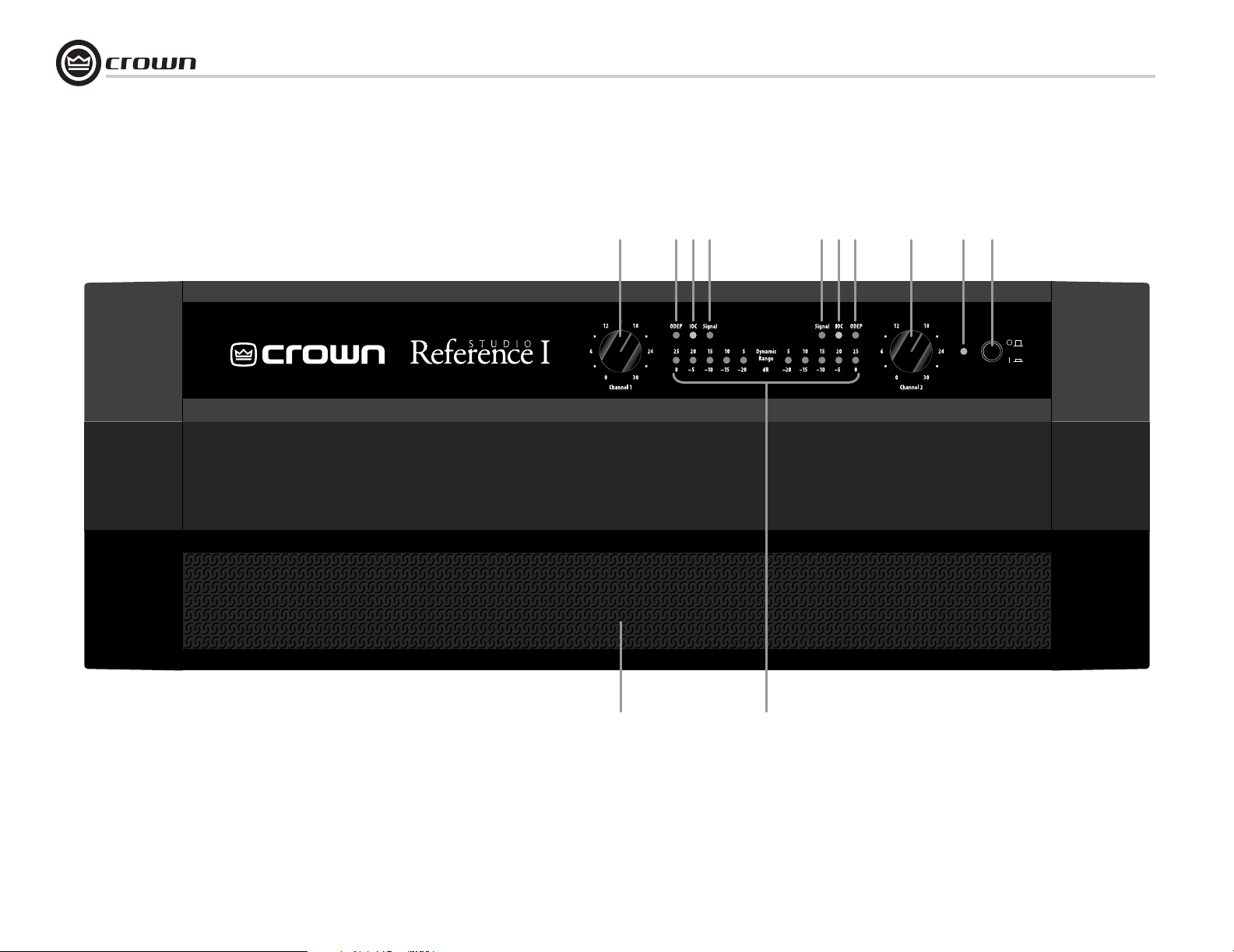
Figure 3.1 Front Panel Controls and Indicators
Operation Manual
Page 15

Studio Reference I & II Professional Studio Amplifiers
3 Operation
3.2 Front Panel Controls and Indicators
A. Level Controls
Each channel’s output level can be adjusted
accurately using the 31-position detented level
controls on the front panel (see Section 4.4.1).
B. ODEP Indicators
During normal operation of the amplifier, the
ODEP (Output Device Emulation Protection)
indicators glow brightly to show the presence
of reserve thermodynamic energy. They dim
proportionally as energy reserves decrease. In
the rare event that energy reserves are depleted,
the indicators turn off and ODEP proportionally
limits the output drive so the amplifier can
safely continue operating even under severe
conditions. These indicators also help to identify more unusual operating conditions (see
Figure 4.1).
C. IOC Indicators
The IOC (Input Output Comparator) indicators
serve as sensitive distortion indicators to provide proof of distortion-free performance.
Under normal conditions, the indicators remain
off. They flash if the output waveform differs
from the input by 0.05% or more (see
Section 4.2). If the input signal level is too
high, the indicators will also flash brightly with
a half-second hold delay to show input overload or output clipping. Note: The channel 2
IOC indicator stays on in Parallel-Mono mode.
See Section 4.1.
D. Signal Presence Indicators
These indicators flash synchronously with the
amplifier’s audio output to show signal presence. Note: These indicators may not flash at
very low input signal levels. See Section 4.1.
E. Enable Indicator
This indicator lights when the amplifier has
been “enabled” or turned on, and AC power is
available.
F. Enable Switch
This push button is used to turn the amplifier
on and off. When turned on, the output is
muted for about four seconds to protect your
system from start-up transients. This is why a
power sequencer is rarely needed for multiple
units. (The turn-on delay can be changed. Contact Crown’s Technical Support Group for
details.)
G. Dust Filter
The dust filter removes large particles from the
air drawn in by the cooling fan. In most cases,
the fan will not run so the filter will remain
clean. If the filter becomes dirty, it can be
removed for easy cleaning (see Section 4.3).
H. Dynamic Range/Level Meters
A five-segment output meter is provided for
each channel. The meters are factory-set to
show dynamic range of the signals in dB, which
is computed as the ratio of peak to average output power. Also, the meter can optionally be set
to show output levels (see Section 4.1).
• Meter Switches
Two switches behind the front panel can be
used to customize the output meters (H). By
default, the meters display dynamic range. To
make the meters display signal levels or to turn
them off, see Section 4.4.2.
Operation Manual
page 15
Page 16
3 Operation
Studio Reference I & II Professional Studio Amplifiers
page 16
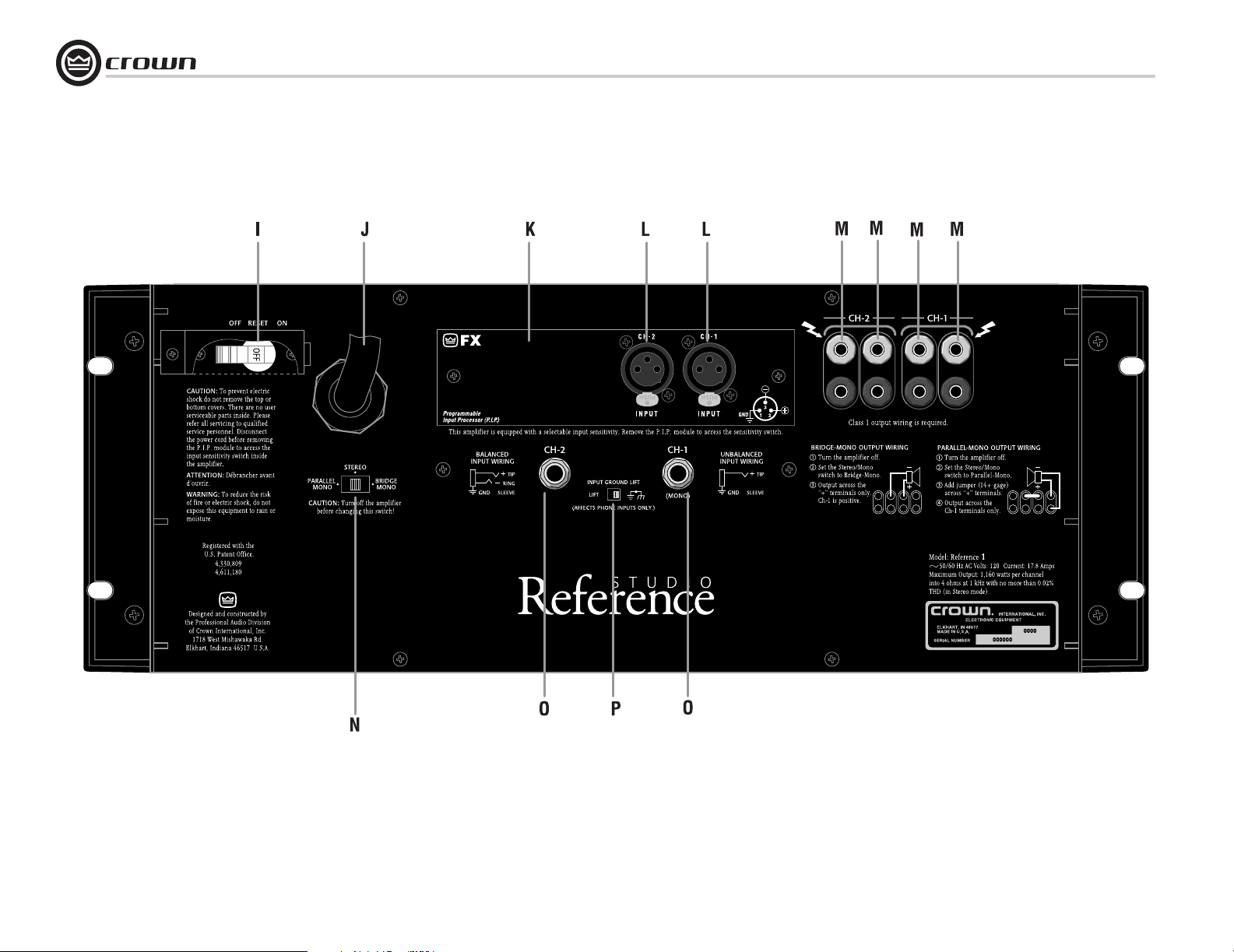
Figure 3.2 Back Panel Connectors and Controls
Operation Manual
Page 17
Studio Reference I & II Professional Studio Amplifiers
3 Operation
3.3 Back Panel Connectors and Controls
I. Reset Switch
This back panel switch can be used to trip and
reset the AC mains circuit breaker (see Section
4.2.4).
J. Power Cord
For 120 VAC, 60 Hz North American units, the
Studio Reference I includes a 10 AWG power
cord and NEMA TT30P plug, and the Studio
Reference II includes a 12 AWG cord and
NEMA 5-15P plug. Other units are shipped
with an appropriate power cord and plug.
K. PIP Module
The standard P.I.P.-FX input module is provided
with your amplifier. It provides female XLR
input connectors. Each pair of XLR and phone
jack connectors is wired in parallel so the
unused connector can be used as a “daisy
chain” output to connect a source to multiple
amplifiers. Other PIP modules can be used in
place of the P.I.P. -FX to provide additional features that customize your amplifier for different
applications (see Section 4.5).
L. Balanced XLR Inputs
A balanced three-pin female XLR connector is
provided on the P.I.P.-FX (K) for input to each
channel. Caution: Do not use the
Channel 2 input in either mono mode.
M. Output Connectors
Two pairs of versatile 5-way binding posts are
provided for the output of each channel so multiple loudspeakers can be connected easily.
They accept banana plugs, spade lugs or bare
wire.
N. Stereo/Mono Switch
This switch is used to select one of three operating modes. Stereo mode is used for normal
two-channel operation, Bridge-Mono mode is
used to drive a single channel with a load
impedance of at least 4 ohms, and ParallelMono mode is used to drive a single channel
with a load impedance of less than 4 ohms.
WARNING: Turn off the amplifier before
changing this switch (see Sections 2.5.1,
2.5.2 and 2.5.3).
O. Balanced Phone Jack Inputs
A balanced 1/4-inch phone jack is provided for
input to each channel. They may be used with
either balanced (tip, ring and sleeve) or unbalanced (tip and sleeve) input wiring (see Section
3.3). These inputs are in parallel with the PIP
connector, so they should not be used as inputs
if the installed PIP has active circuitry.
Caution: Do not use the channel 2 input
in either mono mode.
P. Ground Lift Switch
The input signal ground may be isolated from
the AC ground with this switch to help prevent
unwanted ground loops. It affects only the
phone jacks (O). It has no effect on the PIP
module’s XLR connectors. Activating the switch
inserts an impedance between the sleeve of
each phone input jack and the circuit ground.
See Section 4.4.3.
• Input Sensitivity Switch
The three-position input sensitivity switch
inside the amplifier can be accessed by removing the PIP module. Settings include 0.775
volts and 1.4 volts for rated output, and 26 dB
voltage gain (see Section 4.4.4).
Operation Manual
page 17
Page 18
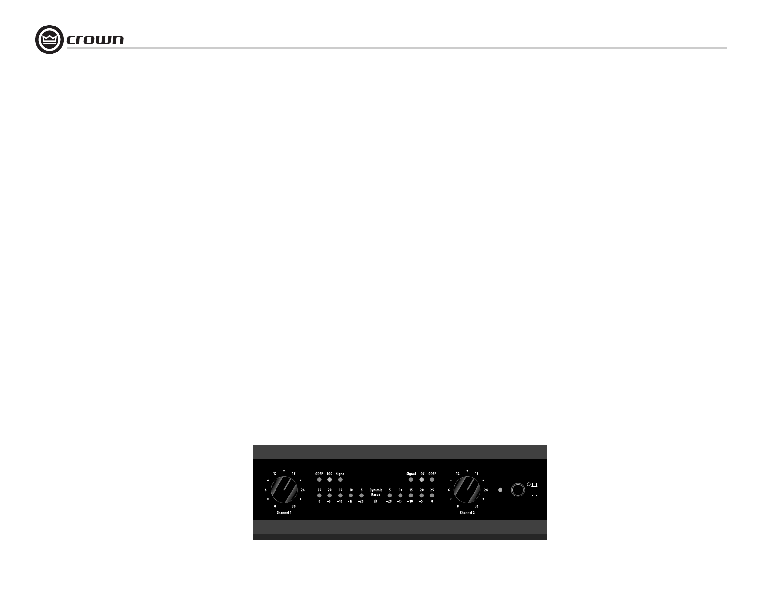
4 Advanced Features and Options
4.1 Indicators
The front panel has several helpful indicators. The
enable indicator is provided to show the amplifier has been turned on (or enabled) and that its
low-voltage power supply and on-demand forced
air cooling system are working. It does not indicate
the status of the high-voltage power supplies. For
example, the enable indicator will stay on in the
improbable event that one or both channels overheat causing an internal shut down of the high voltage supplies.
The green ODEP indicators confirm the normal
operation of Crown’s patented Output Device Emulation Protection circuitry. During normal operation,
they glow brightly to confirm the presence of
reserve thermodynamic energy. They dim proportionally as the energy reserve decreases. In the rare
event that there is no reserve, the indicators will turn
off and ODEP will proportionally limit the drive level
of the output stages so the amplifier can continue
safe operation even when the operating conditions
are severe. (For a more detailed description of
ODEP, see Section 4.2.1.)
A channel’s ODEP indicator also turns off if its highvoltage power supply if it is put in “standby” mode
or the amplifier’s circuit breaker is tripped. The
standby mode is activated if DC or heavy commonmode current is detected in the output, if the transformer thermal protection system is activated, if a
PIP with SmartAmp™ features is used to shut down
a high-voltage supply, or if excessive AC mains
voltage is detected. For more information see Section 4.2 and Chapter 6 on Troubleshooting.
Studio Reference I & II Professional Studio Amplifiers
The yellow IOC indicators act as sensitive distortion meters to provide proof of distortion-free
performance. The IOC (Input/Output Comparator)
circuitry compares the incoming signal’s waveform
to that of the output. Any difference between the two
is distortion. The IOC indicators flash if there is a
difference of 0.05% or more. The IOC indicators
also show input overload by flashing brightly with a
half-second hold delay. It is normal for them to light
momentarily when the amplifier is first turned on.
Note: The channel 2 IOC indicator will stay on in
Parallel-Mono mode. Also, an IOC indicator will
stay on in abnormal situations where a high-voltage
power supply is temporarily put in standby mode.
The green signal presence indicators flash synchronously with the amplifier’s output signal. The
signal detector is connected to the signal path after
the input gain stages and level controls, so a flashing indicator tells you that there is audio in and out
of the amplifier. Note: The signal presence indicators may not report signal presence if the output
signal level is too low.
The dynamic range/level meters are five-segment output meters that can be set to monitor either
the dynamic range or the level of the output signal.
They are factory-set to show dynamic range. A
switch located behind the front panel is used to
select the meter display mode (see Section 4.4.2 for
complete instructions). As dynamic range meters
they show each channel’s ratio of peak-to-average
power in dB. The dynamic range may be low for
sources like AM/FM radio or low-quality record-
ings. Other sources like live music or high-quality
recordings may be much higher. As output level
meters they show how high the output levels are in
dB relative to full power. At 0 dB, the unit is delivering full standard 1 kHz power (see Section 7).
4.2 Protection Systems
Studio Reference amplifiers provide extensive protection and diagnostics capabilities. Protection systems include ODEP, standby mode, an AC circuit
breaker and transformer thermal protection. These
systems will prevent amplifier damage in virtually
any situation.
4.2.1 ODEP
Crown invented ODEP to solve two long-standing
problems in amplifier design: to prevent amplifier
shutdown during demanding operation and to
increase the efficiency of output circuitry.
To do this, Crown established a rigorous program to
measure the safe operating area (SOA) of each output transistor before installing it in an amplifier.
Next, Crown designed intelligent circuitry to simulate the instantaneous operating conditions of the
output transistors. Its name describes what it does:
Output Device Emulation Protection or ODEP. In
addition to simulating the operating conditions of
the output transistors, it also compares their operation to their known SOA. If ODEP sees that more
power is about to be asked of the output transistors
than they are capable of delivering under the present
conditions, ODEP immediately limits the drive level
until it falls within the SOA. Limiting is proportional
and kept to an absolute minimum—only what is
required to prevent output transistor damage.
page 18
Figure 4.1 Indicators
Operation Manual
Page 19

Studio Reference I & II Professional Studio Amplifiers
4 Advanced Features and Options
This level of protection enables Crown to increase
output efficiency to never-before-achieved levels
while greatly increasing amplifier reliability.
The on-board intelligence is monitored two ways.
First, the amplifier’s ODEP indicators show whether
the unit is functioning correctly or if ODEP is limiting output. Second, ODEP data is fed to the amplifier’s internal PIP connector so advanced PIP
modules like the IQ-PIP can use it to monitor and
control the amplifier.
This is how ODEP keeps the show going with maximum power and maximum protection at all times.
4.2.2 Standby Mode
An important part of a Studio Reference amplifier’s
protection systems is standby mode. Standby protects the amplifier during potentially catastrophic
conditions. It temporarily removes power from the
high-voltage supplies to protect the amplifier and its
loads. Standby mode can be identified using the
Troubleshooting chart in Chapter 6.
Standby mode is activated in five situations. First,
when you turn on the enable switch, standby mode
is activated to provide turn-on protection. This
power-up delay lets other system components settle
before any signals are amplified and it provides
some power-up “randomness” for multiple units so
the system’s start-up current demands are better
distributed over time.
The amplifier’s overvoltage protection circuitry
will put both channels into standby when excessive
AC mains voltage is detected. Studio Reference
amplifiers should not be operated with an AC mains
voltage of more than 10% over the unit’s rated voltage.
If dangerous subsonic frequencies or direct current
(DC) is detected in the amplifier’s output, the unit
will activate its DC/low-frequency protection
circuitry and put the affected channels in standby.
This protects the loads and prevents oscillations.
The amplifier resumes normal operation as soon as
it no longer detects dangerous low-frequency or DC
output. Although it is extremely unlikely that you
will ever activate the amplifier’s DC/low-frequency
protection system, improper source materials such
as subsonic square waves or input overloads that
result in excessively clipped signals can activate
this system.
The amplifier’s fault protection system will put an
amplifier channel into standby mode in rare situations where heavy common-mode current is
detected in the channel’s output. The amplifier
should never output heavy common-mode current
unless its circuitry is damaged in some way, and
putting the channel into standby mode helps to prevent further damage.
The amplifier’s transformer thermal protection
circuitry is activated in very unusual circumstances
where the unit’s transformer temperature rises to
unsafe levels. Under these abnormal conditions, the
amplifier will put both channels into standby mode.
The amplifier will return to normal operation after
the transformer cools to a safe temperature. (For
more information on transformer thermal protection,
refer to the section that follows.)
4.2.3 Transformer Thermal Protection
All Studio Reference amplifiers have transformer
thermal protection which protects the power supplies from damage under rare conditions where the
transformer temperature rises too high. A thermal
switch embedded in the transformer removes power
to the high-voltage power supplies if it detects
excessive heat. The switch automatically resets
itself as soon as the transformer cools to a safe temperature.
If your amplifier is operated within rated conditions,
it is extremely unlikely that you will ever see it activate transformer thermal protection. One reason is
that ODEP keeps the amplifier working under very
severe conditions. Even so, higher than rated output
levels, excessively low-impedance loads and unreasonably high input signals can generate more heat
in the transformer than in the output devices. This
can overheat the transformer and activate its protection system.
Studio Reference amplifiers are designed to keep
working under conditions where other amplifiers
would fail. But even when the limits of a Studio Reference amplifier are exceeded, it still protects
itself—and your investment—from damage.
4.2.4 Circuit Breaker
A back panel circuit breaker is provided to prevent
excessive current draw by the high-voltage power
supplies. A Studio Reference I configured for 100 to
120 VAC has a 30 amp circuit breaker, while the 220
to 240 VAC version has a 20 amp circuit breaker. A
Studio Reference II configured for 100 to 120 VAC
uses a 20 amp circuit breaker, and the 220 to
240 VAC version has a 10 amp circuit breaker. With
rated loads and output levels, this breaker should
only trip in the incredibly rare instance of a catastrophic amplifier failure. The ODEP system keeps
the amplifier safe and operational under most other
severe conditions. The breaker can also trip in situations where extremely low-impedance loads and
high output levels result in current draw that
exceeds the breaker’s rating. Again, this should only
be possible when operating outside rated conditions, like when the amplifier is used to drive a 1
ohm load, or when an input signal is clipped
severely.
4.3 Filter Cleaning
A dust filter is provided on the amplifier’s air intake
(see Figure 3.1). If this filter becomes clogged, the
unit will not cool as efficiently as it should and high
heat sink temperatures may produce lower-thannormal output.
Dust filters are not 100% efficient—depending on
the local environment, the internal heat sinks of the
amplifier will benefit from periodic cleaning by a
qualified technician. Internal cleaning information is
available from our Technical Support Group.
Operation Manual
page 19
Page 20
4 Advanced Features and Options
4.4 Controls
4.4.1 Level Controls
Each of the front panel level controls has 31
detents for accurately repeatable settings. In
Bridge-Mono and Parallel-Mono modes, the
channel 2 level control should be turned down.
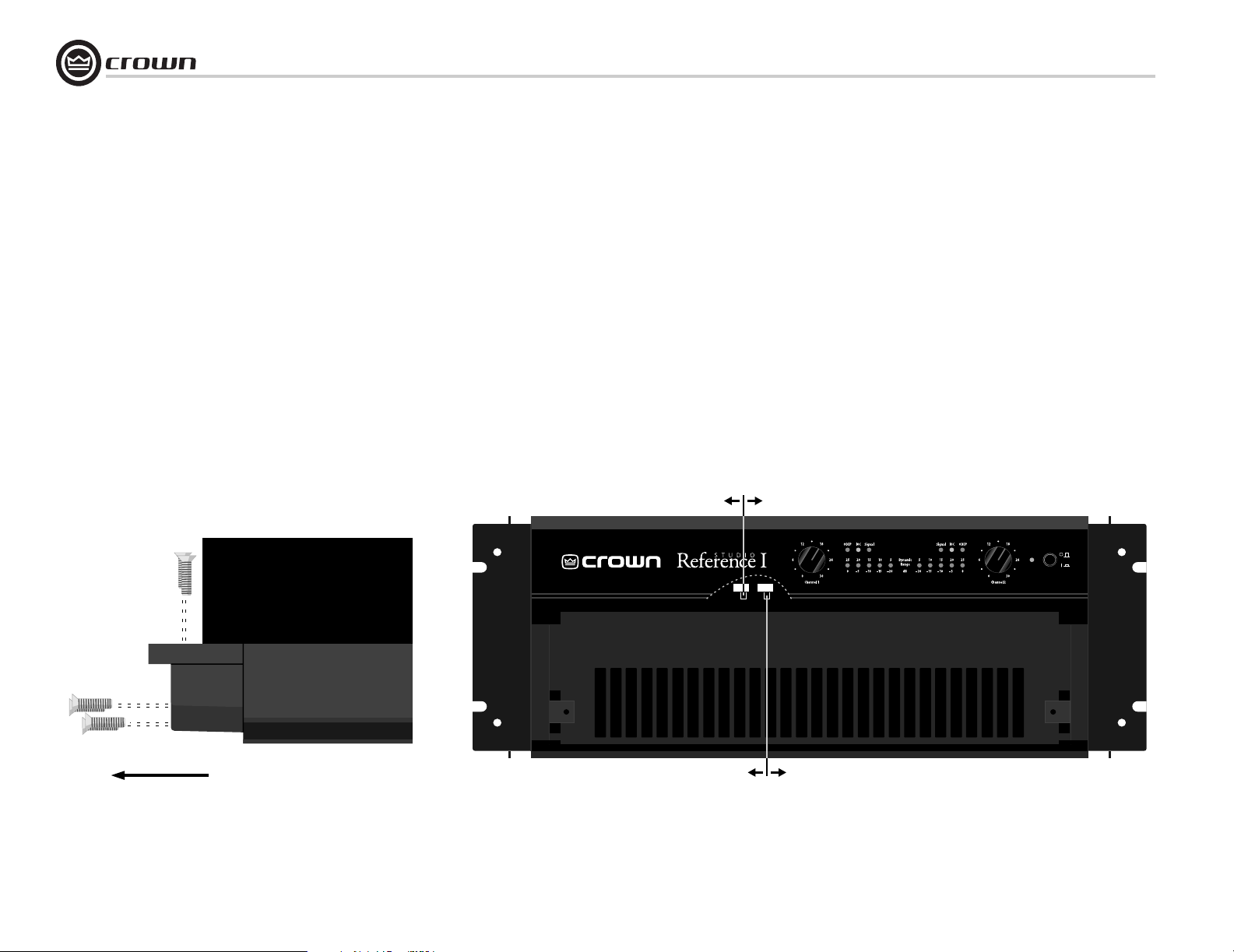
4.4.2 Meter Switches
The meter switches are located behind the front
panel. They make it possible to switch between
the dynamic range and signal level display
modes for the meters, or you can turn the
meters off. From the factory, the meters automatically display dynamic range (which is
computed as the ratio of peak to average output
power). To change these switches, you will
need to remove part of the front panel. A phillips screwdriver will be needed, and it will help
to remove the amplifier if it is mounted in a
rack. Follow these steps:
1. Make sure the amplifier is turned off and its
power cord is disconnected from the AC mains
source.
2. Remove the two screws that hold each end
cap in place and remove both end caps (see
Figure 2.1).
3. Remove the six screws that hold each handle
in place and remove each handle (see Figure
4.2).
Studio Reference I & II Professional Studio Amplifiers
4. Remove the dust filter by gently pulling it
away from the front panel.
5. Remove the two screws that secure the lower
half of the front panel and remove the lower
front panel.
6. Locate the meter switches as shown in
Figure 4.3. Set the switches as desired. The left
switch is used to turn the meters on and off,
and the right switch is used to change display
modes.
7. Reassemble the front panel, handles and end
caps in reverse order of disassembly.
8. Install the amplifier and reconnect power.
page 20
AMPLIFIER TOP VIEW
(FRONT LEFT CORNER—END CAP REMOVED)
To remove the handle,
pull firmly from the side.
Figure 4.2 Removing a Handle
METER ON/OFF SWITCH
ONOFF
®
DYNAMIC RANGEOUTPUT LEVEL
METER MODE SWITCH
Figure 4.3 Meter Switches
Operation Manual
Page 21
Studio Reference I & II Professional Studio Amplifiers
4 Advanced Features and Options
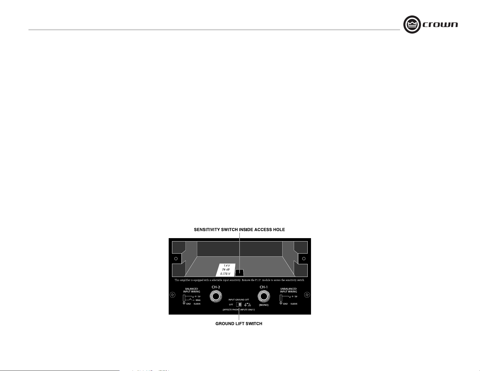
4.4.3 Ground Lift Switch
The ground lift switch located on the back panel can
provide isolation between the phone jack input
grounds and the AC (chassis) ground. It does not
affect the PIP module’s input connectors. Slide the
switch to the left to isolate or “lift” the grounds.
Note: The noninverted and inverted signal lines for
the PIP module are connected in parallel with the
corresponding lines of the phone jack inputs. The
input signal grounds are not paralleled. Specifically,
XLR pins 2 and 3 are connected in parallel with the
tip and ring of the corresponding phone jack. However, pin 1 of the XLR is not connected in parallel
with the sleeve of the phone jack. This makes it possible for a PIP module to handle its own signal
grounds independently.
The amplifier’s circuit breaker protects the power
supplies from overload. The breaker’s reset switch is
located on the back panel. Facing the back panel,
move the reset switch the left to disconnect power to
the power supplies, or to the right to reconnect
power. If the circuit breaker trips, the front panel
enable indicator will turn off. If this occurs, turn off
the enable switch, flip the reset switch to the right
(on), and then turn the enable switch back on. If it
trips again or the amplifier does not operate properly, contact an authorized service center or Crown’s
Technical Support Group.
4.4.4 Input Sensitivity Switch
The input sensitivity switch is located inside the
amplifier’s PIP compartment. It is factory-set to a
fixed voltage gain of 26 dB. For standard 1 kHz
power into 8 ohms, this is equivalent to an input
sensitivity of 4.0 volts for the Studio Reference I and
2.7 volts for the Studio Reference II. If needed, it can
be switched to a sensitivity of 0.775 or 1.4 volts.
Here is the procedure:
1. Turn off the amplifier and disconnect the power
cord from the receptacle.
2. Remove the PIP module.
3. Locate the access hole for the sensitivity switch
inside the chassis opening (see Figure 4.4).
4. Set the switch to the desired position noted on
the access hole label.
5. Replace the PIP module and restore power.
4.5 PIP Modules
Versatile PIP (Programmable Input Processor) and
PIP2 modules provide flexible expansion features
that can be added to customize the amplifier. The
modules plug into the connector inside the back
panel of the amplifier. The modules are available
with features ranging from error-driven compressors/limiters to crossovers to IQ
Crown website at www.crownaudio.com, or contact
Crown Customer Service, for descriptions of available PIP and PIP2 modules.
®
control. Visit the
Operation Manual
Figure 4.4 Input Sensitivity and Ground Lift Switches
page 21
Page 22
5 Principles of Operation
Studio Reference I & II Professional Studio Amplifiers
BALANCED
INPUTS
XLR
1/4" PHONE
5.1 Overview
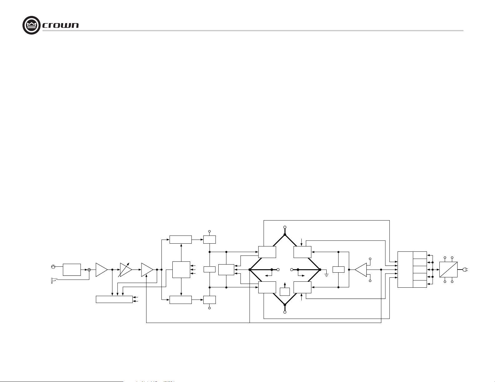
Studio Reference amplifiers incorporate several new technological advancements including real-time computer
simulation of output transistor stress, low-stress output
stages, an advanced heat sink embodiment and the Programmable Input Processor (PIP) expansion system.
Custom circuitry is incorporated to limit temperature and
current to safe levels making it highly reliable and tolerant
of faults. Unlike many lesser amplifiers, it can operate at
its voltage and current limits without selfdestructing.
Studio Reference amplifiers are protected against all common hazards that plague high-power amplifiers including
shorted, open or mismatched loads; overloaded power
supplies, excessive temperature, chain-destruction phenomena, input overload and high-frequency blowups. The
unit protects loudspeakers from input and output DC, as
well as turn-on and turn-off transients.
Real-time computer simulation is used to create an analogue of the junction temperature of the output transistors
P.I.P.
BALANCE
INPUT STAGE
DISPLAY
VARIABLE
GAIN STAGE
ERROR
D
E
AMP
TRANSLATOR
ODEP
TRANSLATOR
(hereafter referred to as the output devices). Current is limited only when the device temperature becomes excessive—and only by the minimum amount necessary. This
patented approach maximizes the available output power
and eliminates overheating—the major cause of device
failure.
Crown also invented the four-quadrant topology used in
the output stages of each Studio Reference amplifier (see
Figure 5.1). This special circuitry is called the grounded
bridge. It makes full use of the power supply by delivering
peak-to-peak voltages to the load that are twice the voltage
seen by the output devices.
As its name suggests, the grounded bridge topology is referenced to ground. Composite devices are constructed to
function as gigantic NPN and PNP devices to handle currents which exceed the limits of available devices. Each
output stage has two composite NPN and two composite
PNP devices.
The devices connected to the load are referred to as “highside NPN and PNP” and the devices connected to ground
+Vcc
LVA
NPN HI
OUTPUT
STAGE
(DISPLAY)
D
PNP HI
OUTPUT
STAGE
OUTPUT
A
B
C
BIAS
LVA
–Vcc
CURRENT
LIMIT
+
C
(ODEP)
HS
TEMP
+Vcc
–Vcc
A
(ODEP)
NPN LOW
OUTPUT
STAGE
(DISPLAY)
PNP LOW
OUTPUT
STAGE
B
(ODEP)
are referred to as “low-side NPN and PNP.” Positive current is delivered to the load by increasing conductance
simultaneously in the high-side NPN and low-side PNP
stage, while synchronously decreasing conductance of the
high-side PNP and low-side NPN.
The two channels may be used together to double the voltage (Bridge-Mono) or the current (Parallel-Mono) presented to the load. This feature gives you the flexibility to
maximize power available to the load.
A wide bandwidth, multiloop design is used for state-ofthe-art compensation. This produces ideal behavior and
results in ultra-low distortion values.
Aluminum extrusions are used widely for heat sinks in
power amplifiers due to their low cost and reasonable performance. However, measured on a watts per pound or
watts per volume basis, the extrusion technology doesn’t
perform nearly as well as the heat sink technology developed for Studio Reference amplifiers.
+Vcc
+24
POWER
–24
SUPPLY
–Vcc
POWER
SUPPLY
CONTROL
ENABLE
TIMER
DC/LF
OVER
VOLTAGE
FAULT
+Vcc
E
BIAS
BRIDGE
BALANCE
–Vcc
page 22
ONLY ONE CHANNEL SHOWN
Figure 5.1
Circuit Block Diagram
Operation Manual
Page 23

Studio Reference I & II Professional Studio Amplifiers
5 Principles of Operation
Our heat sinks are fabricated from custom convoluted fin
stock that provides an extremely high ratio of area to volume, or area to weight. All power devices are mounted
directly to the heat sinks which are also electrically at the
Vcc potential. Electrifying the heat sinks improves thermal
performance by eliminating the insulating interface underneath the power devices. The chassis itself is even used as
part of the thermal circuit to maximize utilization of the
available cooling resources.
5.2 Circuit Theory
Power is provided by low-field toroidal power transformer
T1. The secondaries of T1 are full-wave rectified (by D1
through D4, D22 and D24) and filtered by large computer
grade capacitors. A thermal switch embedded in the transformer protects it from overheating. Monolithic regulators
provide a regulated ±15 volts.
5.2.1 Stereo Operation
For simplicity, the discussion of Stereo operation will refer
to only one channel. Mono operation will be discussed
later. Please refer to the block diagram in Figure 5.1.
The input signal at the phone jack passes directly into the
balanced gain stage (U104-A). When a PIP module is
used, the input signal first passes through the PIP ’s circuitry and then to the balanced gain stage.
The balanced gain stage (U104-A) causes balanced to single-ended conversion using a difference amplifier. From
there, gain can be controlled with the front panel level controls and the input sensitivity switch. The error amp
(U104-C) amplifies the difference between the output signal and the input signal from the gain pot, and drives the
voltage-translator stage.
From the error amp, the voltage translator stage channels
the signal to the Last Voltage Amplifiers (LVAs) depending
on the signal polarity. The +LVA (Q104 and Q105) and the
–LVA (Q110 and Q111) drive the fully complementary output stage with their push-pull effect through the bias servo
Q318.
The bias servo Q318 is thermally coupled to the heat sink,
and sets the quiescent bias current in the output stage to
lower the distortion in the crossover region of the output
signal.
With the voltage swing provided by the LVAs, the signal
then gains current amplification through the triple Darlington emitter-follower output stage.
The bridge-balanced circuit (U104-D) receives a signal
from the output of the amplifier, and differences it with the
signal at the Vcc supply. The bridge-balanced circuit then
develops a voltage to drive the bridge-balanced output
stage. This results in the Vcc supply having exactly one
half of the output voltage added to its quiescent voltage.
Bias servo Q300 sets the quiescent current point for the
bridge-balanced output stage.
The protection mechanisms that affect the signal path are
implemented to protect the amplifier under real-world conditions. These conditions are high instantaneous current,
excessive temperature, and output device operation outside safe conditions.
Q107 and Q108 act as a conventional current limiter, sensing current in the output stage. When output current at any
instant exceeds the design criteria, the limiters remove
drive from the LVAs, thus limiting current in the output
stage to a safe level.
To further protect the output stages, the patented ODEP
circuitry is used. It produces an analog output proportional to the always changing safe operating area of the
output transistors. This output controls the translator stage
previously mentioned, removing any further drive that may
exceed the safe operating area of the output stage.
Thermal sensor S100 gives the ODEP circuit vital information on the operating temperature of the heat sink on which
the output devices are mounted.
Should the amplifier fail in such a way that would cause
DC across the output leads, the DC/low-frequency protection circuit senses this on the negative feedback loop and
shuts down the power supply until the DC is removed.
5.2.2 Bridge-Mono Operation
By setting the back panel stereo/mono switch to BridgeMono, the user can convert the amplifier into a bridged,
single-channel amplifier. With a signal applied to the
channel 1 input jack and the load connected across the
two channels’ red (+) 5-way binding posts, twice the voltage can be output.
The channel 1 output feeds the channel 2 error amp U204C. Because there is a net inversion, channel 2 output is out
of polarity with channel 1. This produces twice as much
voltage across the load. Each channel’s protection mechanisms work independently if a fault occurs.
5.2.3 Parallel-Mono Operation
With the stereo/mono switch set to Parallel-Mono, the output of channel 2 is paralleled with the output of channel 1.
A suitable jumper capable of handling high current must
be connected across the red (+) 5-way posts to gain the
benefits of this mode of operation.
The signal path for channel 1 is the same as previously
discussed, except channel 1 also drives the output stage of
channel 2. The channel 2 balanced input, error amp, translators and LVAs are disconnected and no longer control
the channel 2 output stage. Disconnecting the front-end
stages from the channel 2 output causes the channel 2 IOC
circuit to note that the input waveform (which is not
present) does not match the output waveform (which is
driven by the channel 1 input signal). This activates the
channel 2 IOC indicator any time the amplifier is switched
into Parallel-Mono mode. The channel 2 output stage and
protection mechanisms are also coupled through S1 and
function as one.
In Parallel-Mono mode, twice the current of one channel
alone can be obtained. Because the channel 2 ODEP circuit is coupled through S1, this gives added protection if a
fault occurs in the channel 2 output stage. The ODEP circuit of channel 2 will limit the output of both output stages
by removing the drive from the channel 1 translator stages.
Operation Manual
page 23
Page 24
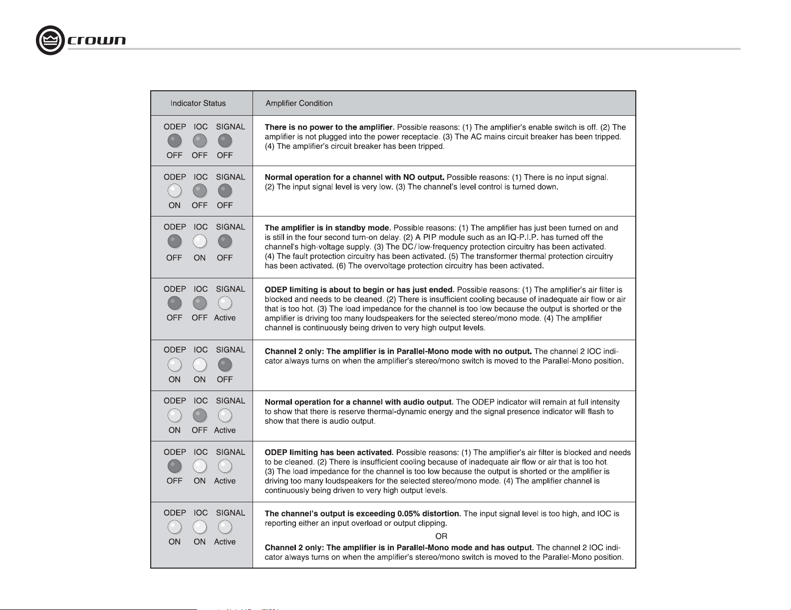
6 Troubleshooting
Studio Reference I & II Professional Studio Amplifiers
page 24
Operation Manual
Page 25
Studio Reference I & II Professional Studio Amplifiers
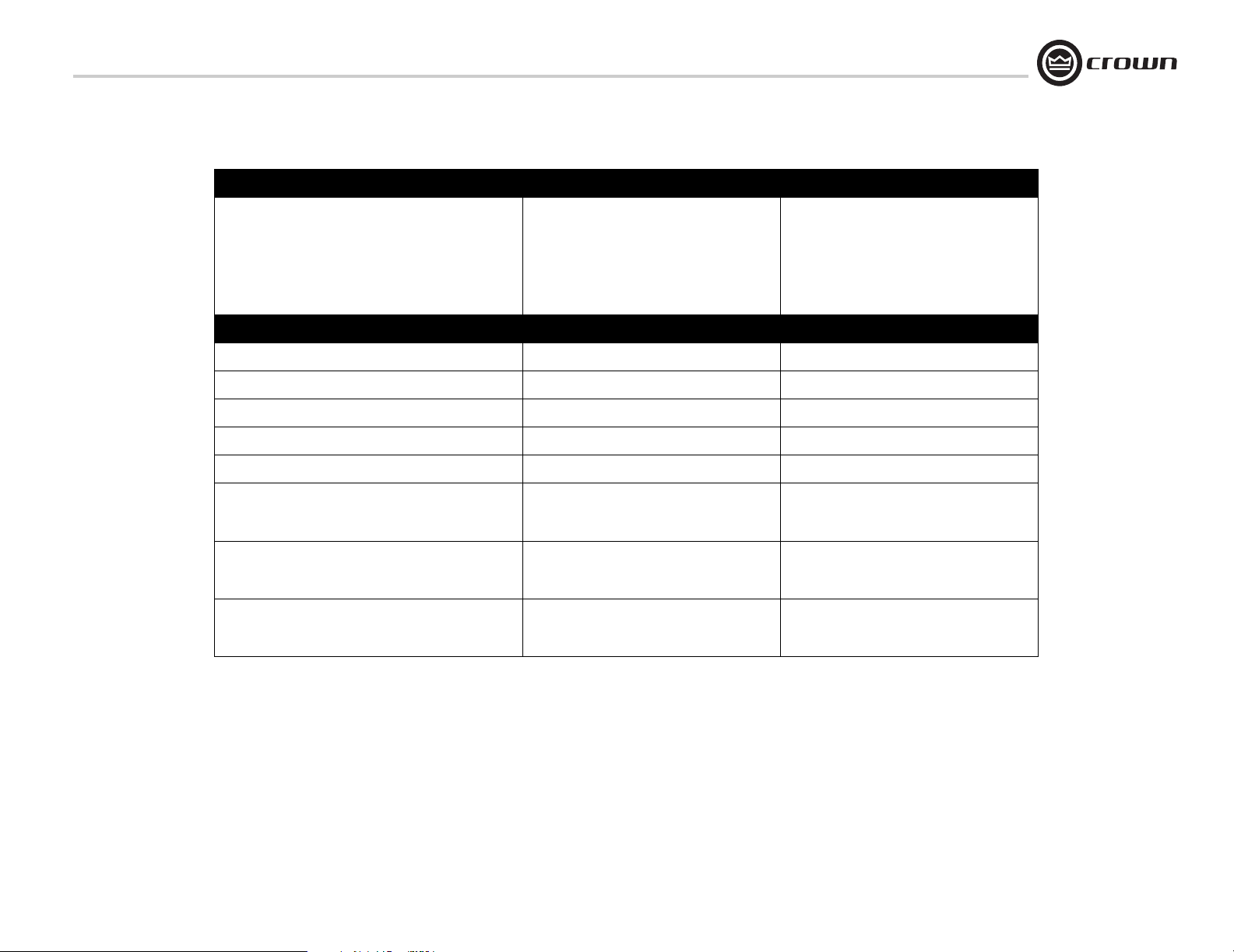
7 Specifications
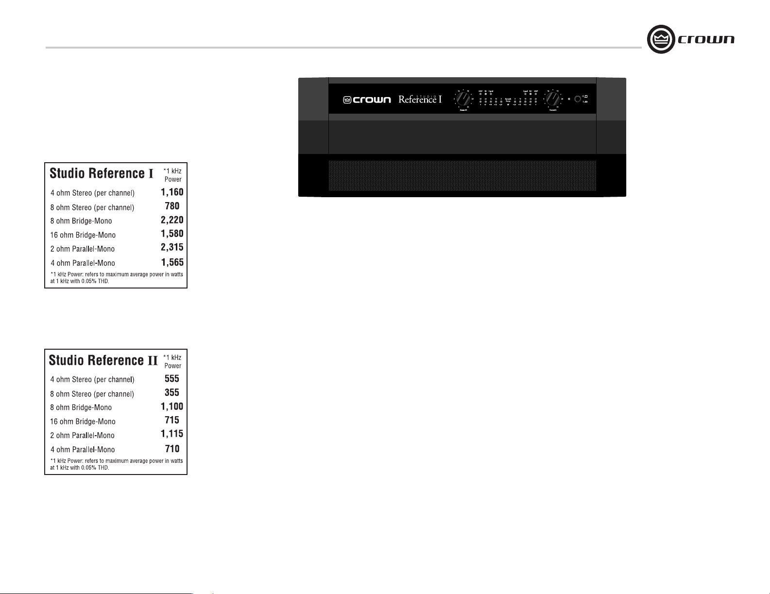
Minimum Guaranteed Power Studio Reference I Studio Reference II
1 kHz with 0.05% THD
Stereo, 4 ohms (per ch.)
Stereo, 8 ohms (per ch.)
Bridge mono, 8 ohms
Bridge mono, 16 ohms
Parallel mono, 2 ohms
Parallel mono, 4 ohms
Performance Studio Reference I Studio Reference II
Sensitivity (volts RMS) for full rated power at 8 ohms 0.775V, 1.4 V, or 26 dB gain 0.775V, 1.4 V, or 26 dB gain
Frequency Response (at 1 watt, 20 Hz - 20 kHz) (see Figure 7.5) ± 0.1 dB ± 0.1 dB
Phase Response (at 1 watt , 20 Hz to 20 kHz) (see Figure 7.8) +5° to –15° +5° to –15°
Signal to Noise Ratio below rated full bandwidth power, A-weighted > 120 dB > 117 dB
Total Harmonic Distortion (THD) at full bandwidth power < 0.1% < 0.1%
Intermodulation Distortion (IMD) 60 Hz and 7 kHz at 4:1,
from full bandwidth power to 78 watts
from full bandwidth power to 36 watts
Damping Factor (see Figure 7.6)
10 Hz to 200 Hz
1 kHz
< 0.005% rising linearly to 0.025% at 78 milliwatts
1,160W
780W
2,220W
1,580W
2,315W
1,565W
> 20,000
> 2,500
555W
355W
1,100W
715W
1,115W
710W
< 0.005% rising linearly to 0.025% at 36 milliwatts
> 20,000
> 2,500
Operation Manual
Crosstalk (below rated full bandwidth power)
20 Hz to 400 Hz
20 kHz (see Figure 7.10)
> 100 dB
> 70 dB
> 100 dB
> 65 dB
page 25
Page 26
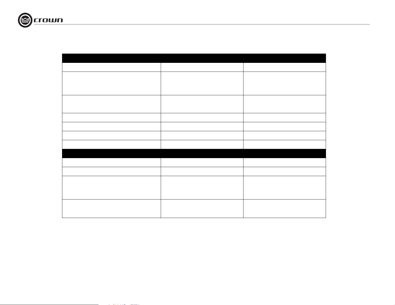
7 Specifications
Studio Reference I & II Professional Studio Amplifiers
Performance Studio Reference I Studio Reference II
Input Impedance (nominally balanced, nominally unbalanced) 10 kilohms, 5 kilohms 10 kilohms, 5 kilohms
Load Impedance (Note: Safe with all types of loads)
Stereo
Bridge Mono
Parallel Mono
4-8 ohms
8-16 ohms
2-4 ohms
4-8 ohms
8-16 ohms
2-4 ohms
Voltage Gain (at maximum level setting) 103:1 ± 6% or 40 dB ±0.5 dB at 0.775-volt sensitivity
Output Impedance < 10 milliohms in series with 2.5 microhenries < 10 milliohms in series with 2.5 microhenries
DC Output Offset (shorted input) ± 2 millivolts ± 2 millivolts
AC Line Voltage and Frequency Configurations Available (± 10%) 50 or 60 Hz; 100, 120, 200, 220 or 240 VAC (± 10%) 50 or 60 Hz; 100, 120, 200, 220 or 240 VAC (± 10%)
Power draw at idle 90W 90W
Construction Studio Reference I Studio Reference II
Ventilation Flow-through ventilation from front to sides Flow-through ventilation from front to sides
Cooling On-demand proportional speed fan On-demand proportional speed fan
Dimensions EIA Standard 19-inch rack mount width (EIA RS-310B),
Weight
Net
Shipping
57:1 ± 6% or 35 dB ± 0.5 dB at 1.4-volt sensitivity
20:1 ± 6% at 26 dB gain ± 0.5 dB
7-inch (17.8-cm) height and 16-inch (40.6-cm) depth
behind mounting surface and 2.75 inch (7 cm) protru-
sion in front of mounting surface
60.7 pounds (27.6 kg)
74.2 pounds (33.7 kg)
69:1 ± 6% or 37 dB ± 0.5 dB at 0.775-volt sensitivity
38:1 ± 6% or 32 dB ± 0.5 dB at 1.4-volt sensitivity
20:1 ± 6% at 26 dB gain ± 0.5 dB
EIA Standard 19-inch rack mount width (EIA RS-310B),
7-inch (17.8-cm) height and 16-inch (40.6-cm) depth
behind mounting surface and 2.75 inch (7 cm) protru-
sion in front of mounting surface
56.1 pounds (25.5 kg)
69.6 pounds (31.6 kg)
page 26
Operation Manual
Page 27

Studio Reference I & II Professional Studio Amplifiers
7 Specifications
Crown specifications are guaranteed for
three years.
In an effort to provide you with as much information as possible about the high power-producing
capabilities of your amplifier, we have created the
following power matrices.
7.1 Minimum Guaranteed Power Specifications
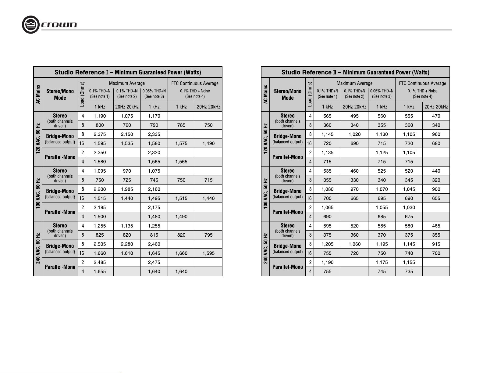
Shown in Figures 7.1 and 7.2, Crown’s minimum power specifications represent the absolute
smallest amount of output power you can expect
from your amplifier when it is driven to full output under the given conditions. Some spaces in
each matrix may be left blank because the same
guarantee is not provided for those conditions—
however, your amplifier will perform well under
all conditions listed in each matrix.
When measuring power, 0.1% THD appears to
be the industry standard for distortion. Two of
the maximum average power specifications
shown in each minimum power matrix are measured at 0.1% THD so you can easily compare
Crown specifications to those of other manufacturers. But this high level of distortion actually
allows for some clipping which is undesirable.
Because of this, a maximum average power
specification at 0.05% THD is included in each
minimum power matrix which represents nonclipped conditions. Also, power at 0.02% THD is
provided in the preceding specifications.
Although most manufacturers do not give power
specifications at 0.05% or 0.02% THD, we
encourage them to provide these specifications
so you will have a more realistic representation
of the way amplifiers should be used in the real
world—without a clipped output signal.
Many manufacturers publish power specs with a
tolerance of ±1 dB or worse. This means their
amplifier can deviate more than 20% in output! A
100 watt amplifier would meet their specification
if it only produced 79.4 watts. Other manufacturers qualify their specs by saying they are “typical,” “subject to manufacturing tolerances,”
“single channel driven” or that they are specified
with “fuses bypassed.” Each of these statements
effectively removes any performance guarantee.
In fact, some manufacturers use these tactics to
generate large power numbers, and they don’t
even print a disclaimer. We take a different
approach at Crown—our amplifiers are guaranteed to meet or exceed their specifications for
three years. We believe you should get what you
pay for.
Minimum Power Notes:
All minimum power specifications are based on
0.5% regulated AC mains with THD of less than
1.0% and an ambient room temperature of 70° F
(21° C). Standard EIA power (RS-490) is not
shown here because it is identical to FTC Continuous Average Power.
1. A 1 kHz sine wave is presented to the amplifier
and the output monitored for nonlinear distortion. The level is increased until THD reaches
0.1%. At this point, average power per channel
is reported.
2. A sine wave is presented to the amplifier over
the range from 20 Hz to 20 kHz and the output
monitored for nonlinear distortion. The level at
each frequency is increased until THD reaches
0.1%. At this point, average power per channel
is reported.
3. A 1 kHz sine wave is presented to the amplifier
and the output monitored for nonlinear distortion. The level is increased until THD reaches
0.05%. At this point, average power per channel
is reported.
4. Continuous power in the context of Federal
Trade Commission testing is understood to be a
minimum of five minutes of operation. Harmonic
distortion is measured as the RMS sum total and
given as a percentage of the fundamental output
voltage. This applies for all wattages greater than
0.25 watts.
Operation Manual
page 27
Page 28
7 Specifications
Studio Reference I & II Professional Studio Amplifiers
page 28
Figure 7.1 Studio Reference I Minimum Power Matrix
Figure 7.2 Studio Reference II Minimum Power Matrix
Operation Manual
Page 29
Studio Reference I & II Professional Studio Amplifiers
7 Specifications
7.2 Maximum Power Specifications
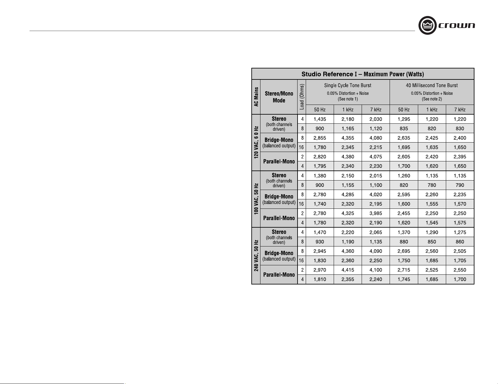
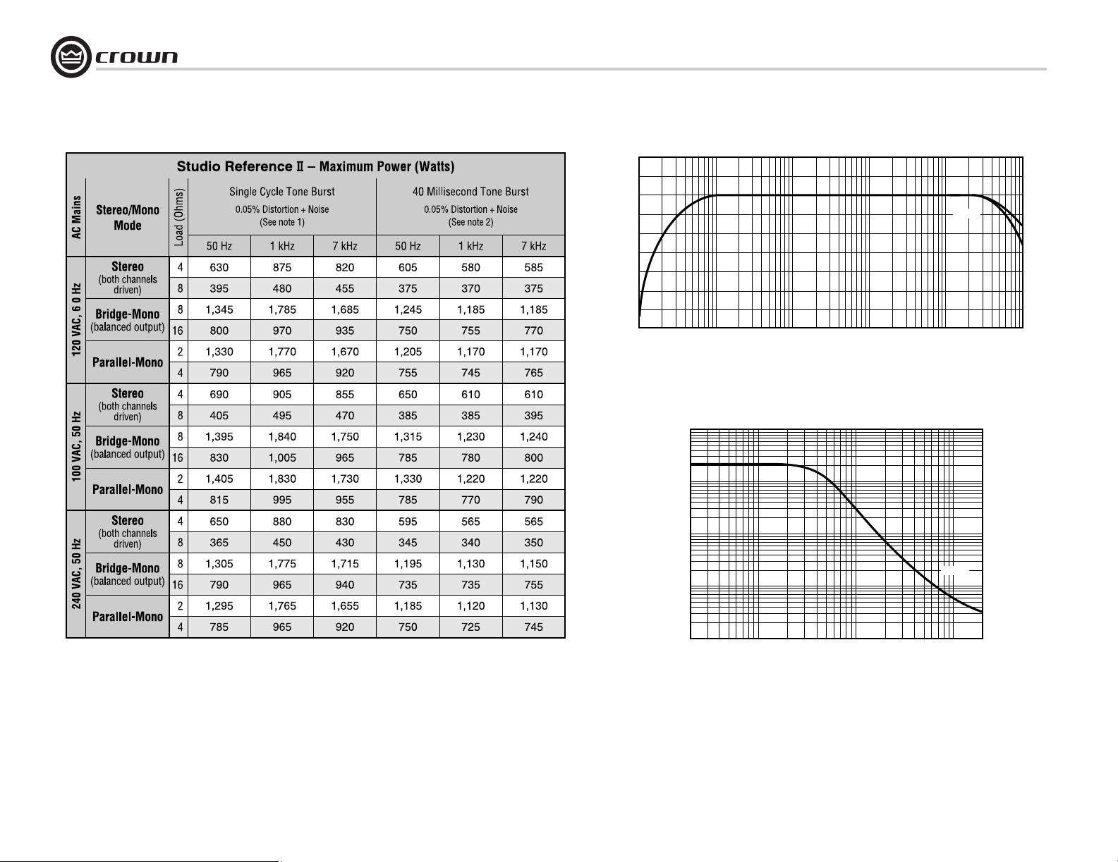
Shown in Figures 7.3 and 7.4, Crown’s maximum power specifications represent the largest
amount of output power you can expect from
your amplifier when it is driven to full output
under the given conditions. These specifications
can be used to prevent loudspeaker and hearing
damage.
The maximum power matrices include specifications for single cycle and 40 millisecond burst
sine waves. Burst signals act like large transient
peaks that are present in common source signals. Loudspeakers can respond to a single
cycle burst, so the single cycle burst specifications should be used to help you protect your
loudspeakers. In contrast, a 40 millisecond burst
represents the typical response time of the
human ear. Your ear will not respond to the
entire dynamic change of a burst that lasts less
than 40 milliseconds.
The burst power specifications are provided at
0.05% THD which is a practical low distortion
condition. Operating the amplifier at levels
higher than 0.05% THD can result in output
power levels that are higher than those listed in
the maximum power matrices.
Maximum Power Notes:
All maximum power specifications are based on
0.5% regulated AC mains with THD of less than
1.0% and an ambient room temperature of 70° F
(21° C). Although it is an unusual condition,
your amplifier can function well with AC mains
voltages up to 10% over the specified line voltage. With overvoltage conditions, your amplifier
may be capable of delivering instantaneous
power levels up to 20% greater than the specifications in the matrix.
1. A single cycle sine wave is presented to the
amplifier and monitored for nonlinear distortion.
The average power during the burst is reported.
Loudspeakers must be able to withstand this
level if they are to be safely used with this amplifier.
2. A 40 millisecond sine wave burst (10 percent
duty cycle) is presented to the amplifier and
monitored for nonlinear distortion. Average
power during the burst is reported. This power
level is a measurement of the amplifier’s maximum transient power that can be perceived by
the human ear.
Operation Manual
Figure 7.3 Studio Reference I Maximum Power Matrix
page 29
Page 30
7 Specifications
Studio Reference I & II Professional Studio Amplifiers
+2
+1
0
–1
–2
dB
–3
–4
–5
–6
–7
10 100 1 K 10 K 100 K
FREQUENCY (Hz)
Figure 7.5 Typical Frequency Response
100,000
1 watt
8 ohm
4 ohm
page 30
Figure 7.4 Studio Reference II Maximum Power Matrix
DAMPING
10,000
1,000
100
10
20 100 1 K 10 K 20 K
FREQUENCY (Hz)
Figure 7.6 Typical Damping Factor
Operation Manual
8 ohm
Page 31
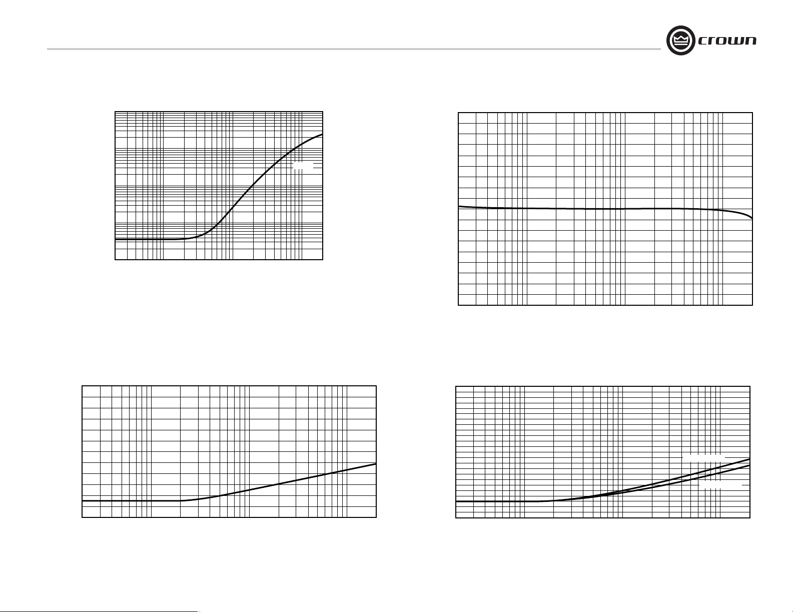
Studio Reference I & II Professional Studio Amplifiers
7 Specifications
1
0.1
OHMS
0.01
0.001
0.0001
20 100 1 K 10 K 20 K
FREQUENCY (Hz)
Figure 7.7 Typical Output Impedance
8 ohm
+135˚
+90˚
+45˚
0˚
–45˚
–90˚
–135˚
10020 1 K 10 K 20 K
FREQUENCY (Hz)
Figure 7.8 Typical Phase Response
0
0
–20
–40
–60dB
–80
–100
–120
Operation Manual
10020 1 K 10 K 20 K
FREQUENCY (Hz)
Figure 7.9 Typical Common Mode Rejection
–20
–40
–60dB
–80
–100
–120
Studio Reference II
Studio Reference I
10020 1 K 10 K 20 K
FREQUENCY (Hz)
Figure 7.10 Typical Crosstalk
page 31
Page 32
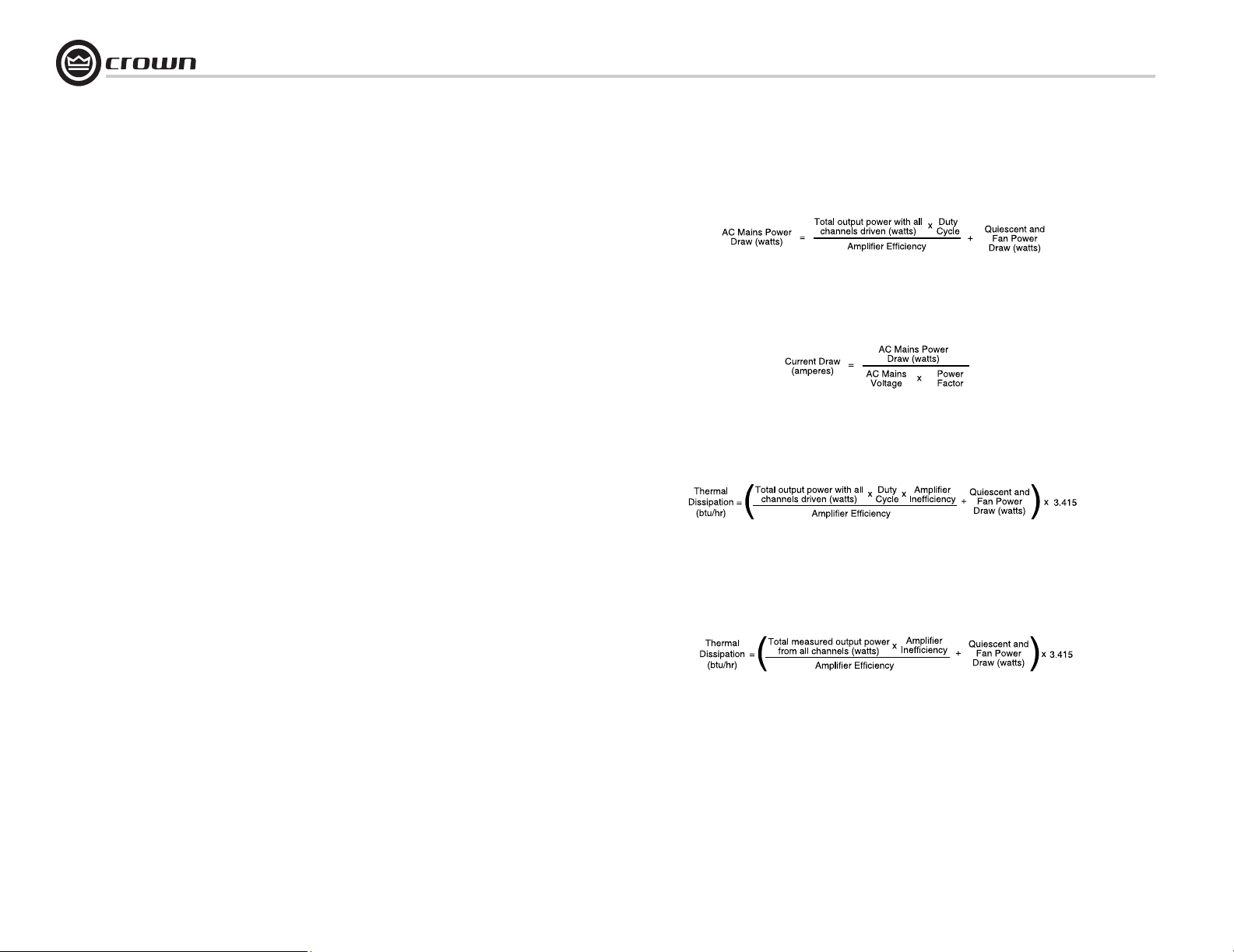
8 AC Power Draw and Thermal Dissipation
This section provides detailed information about the amount of power
and current drawn from the AC mains by Studio Reference amplifiers
and the amount of heat produced under various conditions. The calculations presented here are intended to provide a realistic and reliable
depiction of the amplifiers. The following assumptions or approximations were made:
• The amplifier’s available channels are loaded, and full standard 1 kHz
power is being delivered.
• Amplifier efficiency at standard 1 kHz power is estimated to be 65%.
• Quiescent power draw is 90 watts (an almost negligible amount for
full-power calculations).
• Quiescent thermal dissipation equals 307 btu/hr at 90 watts.
• The estimated duty cycles take into account the typical crest factor for
each type of source material.
• Duty cycle of pink noise is 50%.
• Duty cycle of highly compressed rock ‘n’ roll midrange is 40%.
• Duty cycle of rock ‘n’ roll is 30%.
• Duty cycle of background music is 20%.
• Duty cycle of continuous speech is 10%.
• Duty cycle of infrequent, short duration paging is 1%.
Studio Reference I & II Professional Studio Amplifiers
Here are the equations used to calculate the data presented in Figures
8.1 and 8.2:
The estimated quiescent power draw of 90 watts is a maximum figure,
and assumes that the fan is running at high speed. The following equation converts power draw in watts to current draw in amperes:
The power factor of 0.83 is needed to compensate for the difference in
phase between the AC mains voltage and current. The following equation is used to calculate thermal dissipation:-
page 32
The constant 0.35 is inefficiency (1.00–0.65) and the factor 3.415 converts watts to btu/hr. Thermal dissipation in btu is divided by the constant 3.968 to get kcal. If you plan to measure output power under realworld conditions, the following equation may also be helpful:
Operation Manual
Page 33
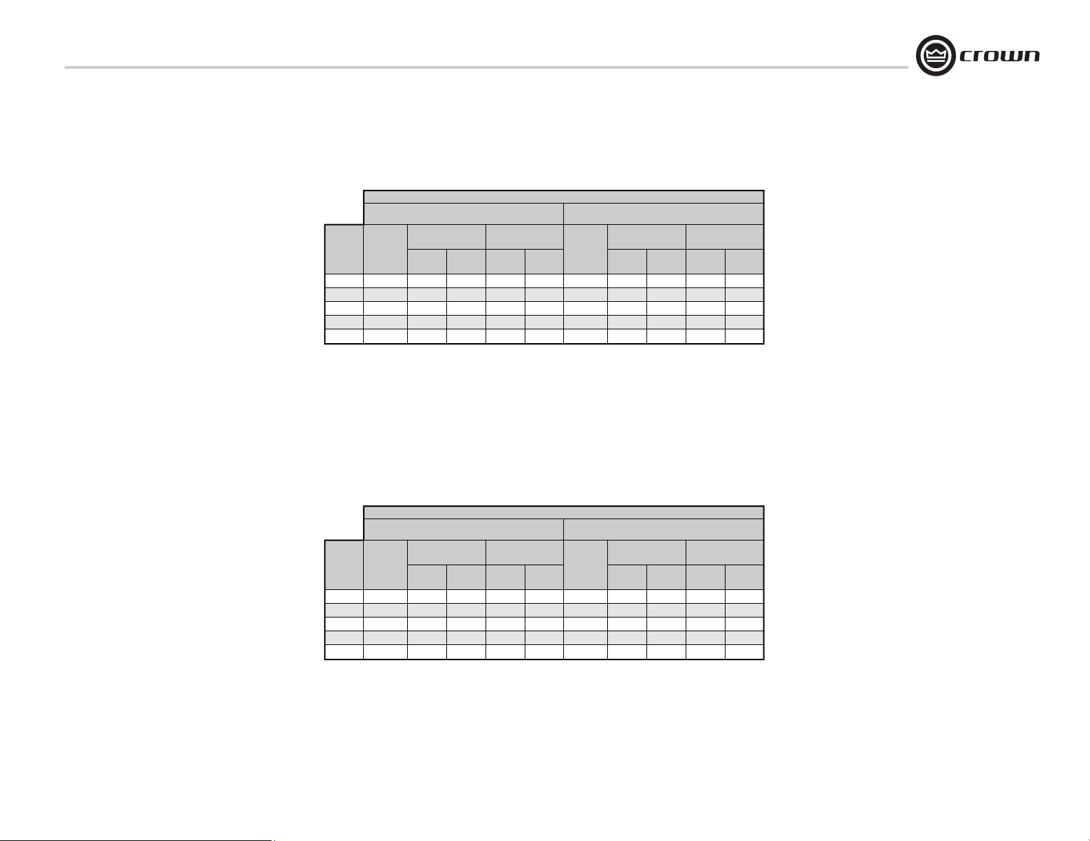
Studio Reference I & II Professional Studio Amplifiers
8 Ohm Stereo / 16 Ohm Bridge-Mono / 4 Ohm Parallel-Mono
AC Mains
Power
Duty
Draw
Cycle
(Watts)
50%
1325
40%
1075
30%
20%
10%
830
585
340
Current Draw (Amps)
100-120 V 220-240 V
7.0
4.1
7.2
5.9
4.5
3.2
1.8
15.9
12.9
10.0
Studio Reference I
L O A D
4 Ohm Stereo / 8 Ohm Bridge-Mono / 2 Ohm Parallel-Mono
Thermal Dissipation
btu/hr
1,780
1,485
1,190
900
605
AC Mains
kcal/hr
450
375
300
230
155
Power
Draw
(Watts)
1,925
1,555
1,190
825
460
Current Draw (Amps)
10.5
23.1
8.5
18.7
6.5
14.3
4.5
9.9
2.5
5.5
Thermal Dissipation
btu/hr
kcal/hr100-120 V 220-240 V
2,500
2,060
1,620
1,185
745
630
520
410
300
190
Figure 8.1 Studio Reference I Power Draw, Current Draw and
Thermal Dissipation at Various Duty Cycles
8 Ohm Stereo / 16 Ohm Bridge-Mono / 4 Ohm Parallel-Mono
Duty
Cycle
50%
40%
30%
20%
10%
AC Mains
Power
Draw
(Watts)
645
535
425
315
205
Current Draw (Amps)
100-120 V 220-240 V
3.5
7.8
2.9
6.4
2.3
5.1
1.7
3.8
1.1
2.4
Figure 8.2 Studio Reference II Power Draw, Current Draw and
Thermal Dissipation at Various Duty Cycles
Studio Reference II
L O A D
4 Ohm Stereo / 8 Ohm Bridge-Mono / 2 Ohm Parallel-Mono
kcal/hr
245
215
180
145
115
AC Mains
Power
(Watts)
Thermal Dissipation
btu/hr
970
840
705
575
440
Draw
975
795
620
445
270
Current Draw (Amps)
5.3
11.7
4.4
9.6
3.4
7.5
2.4
5.3
1.5
3.2
Thermal Dissipation
btu/hr
kcal/hr100-120 V 220-240 V
1,360
1,150
940
730
520
345
290
240
185
135
Operation Manual
page 33
Page 34

9 Service
Studio Reference I & II Professional Studio Amplifiers
Crown amplifiers are quality units that rarely
require servicing. Before returning your unit for
servicing, please contact Crown Technical Support to verify the need for servicing.
This unit has very sophisticated circuitry which
should only be serviced by a fully trained technician. This is one reason why each unit bears
the following label:
CAUTION: To prevent electric shock, do
not remove covers. No user serviceable
parts inside. Refer servicing to a qualified technician.
9.1 Worldwide Service
Service may be obtained from an authorized
service center. (Contact your local Crown/
Amcron representative or our office for a list of
authorized service centers.) To obtain service,
simply present the bill of sale as proof of purchase along with the defective unit to an authorized service center. They will handle the
necessary paperwork and repair.
Remember to transport your unit in the original
factory pack.
9.2 US and Canada Service
Service may be obtained in one of two ways:
from an authorized service center or from the
factory. You may choose either. It is important
that you have your copy of the bill of sale as
your proof of purchase.
9.2.1 Service at a US or Canada Service Center
This method usually saves the most time and
effort. Simply present your bill of sale along
with the defective unit to an authorized service
center to obtain service. They will handle the
necessary paperwork and repair. Remember to
transport the unit in the original factory pack. A
list of authorized service centers in your area
can be obtained from the Crown website at
www.crownaudio.com, or by calling Crown
Customer Service.
9.2.2 Factory Service
To obtain factory service, fill out the service
information page found in the back of this manual and send it along with your proof of purchase and the defective unit to the Crown
factory.
For warranty service, we will pay for ground
shipping both ways in the United States. Contact Crown Customer Service to obtain prepaid shipping labels prior to sending the unit.
Or, if you prefer, you may prepay the cost of
shipping, and Crown will reimburse you. Send
copies of the shipping receipts to Crown to
receive reimbursement.
Your repaired unit will be returned via UPS
ground. Please contact us if other arrangements are required.
9.2.3 Factory Service Shipping Instructions:
1. Before sending a Crown product to the
factory for service, first call the Crown Service Department for a return authorization
(RA) number.
2. Be sure to fill out the service information
form that follows and enclose it with your
shipment, either inside the box or in a
packing slip envelope securely attached to
the outside of the shipping carton. Do not
send the service information form separately. If you are sending the unit from a
Shipping Center, we recommend taping
the form to the product. We also recommend recording the serial number and
model before shipping for your reference.
3. To ensure the safe transportation of your
unit to the factory, ship it in an original
factory packing container. If you don’t have
the original carton, you may obtain a product service foam-in-place shipping pack
from the Crown Factory Service Department at the number listed below. For nonwarranty service, you may also provide
your own shipping pack, however we still
recommend using a Crown Supplied Shipping Container. Minimum recommended
requirements for materials are as follows:
275 P.S.I. burst test Double-Wall carton
that allows for 2-inch solid Styrofoam on
all six sides of unit or 3 inches of plastic
bubble wrap on all six sides of unit;
securely seal the package with an adequate
carton sealing tape. Do not use light boxes
or “peanuts.” Damage caused by poor
packing cannot be covered under warranty.
4. Do not ship the unit in any kind of cabinet
(wood or metal). Ignoring this warning
may result in extensive damage to the unit
and the cabinet. Accessories are not
needed—do not send the product documentation, cables and other hardware.
If you have any questions, please contact
Crown Factory Service.
Crown Factory Service
1718 W. Mishawaka Rd.,
Elkhart, Indiana 46517 U.S.A.
Telephone: 574-294-8200
800-342-6939 (North America,
Puerto Rico, and Virgin Islands only)
Facsimile:
574-294-8301 (Technical Support)
574-294-8124 (Factory Service)
Internet:
http://www.crownaudio.com
page 34
Operation Manual
Page 35

Studio Reference I & II Professional Studio Amplifiers
YEAR
3
10 Warranty
SUMMARY OF WARRANTY
Crown International, 1718 West Mishawaka Road,
Elkhart, Indiana 46517-4095 U.S.A. warrants to
you, the ORIGINAL PURCHASER and ANY SUBSEQUENT OWNER of each NEW Crown product,
for a period of three (3) years from the date of
purchase by the original purchaser (the “warranty
period”) that the new Crown product is free of
defects in materials and workmanship. We further
warrant the new Crown product regardless of the
reason for failure, except as excluded in this Warranty.
ITEMS EXCLUDED FROM THIS
CROWN WARRANTY
This Crown Warranty is in effect only for failure of
a new Crown product which occurred within the
Warranty Period. It does not cover any product
which has been damaged because of any intentional misuse, accident, negligence, or loss which
is covered under any of your insurance contracts.
This Crown Warranty also does not extend to the
new Crown product if the serial number has been
defaced, altered, or removed.
WHAT THE WARRANTOR WILL DO
We will remedy any defect, regardless of the reason for failure (except as excluded), by repair,
replacement, or refund. We may not elect refund
unless you agree, or unless we are unable to provide replacement, and repair is not practical or
cannot be timely made. If a refund is elected, then
you must make the defective or malfunctioning
product available to us free and clear of all liens
or other encumbrances. The refund will be equal
to the actual purchase price, not including inter-
UNITED STATES & CANADA
est, insurance, closing costs, and other finance
charges less a reasonable depreciation on the
product from the date of original purchase. Warranty work can only be performed at our authorized service centers or at the factory. Warranty
work for some products can only be performed at
our factory. We will remedy the defect and ship
the product from the service center or our factory
within a reasonable time after receipt of the defective product at our authorized service center or
our factory. All expenses in remedying the defect,
including surface shipping costs in the United
States, will be borne by us. (You must bear the
expense of shipping the product between any foreign country and the port of entry in the United
States including the return shipment, and all
taxes, duties, and other customs fees for such foreign shipments.)
HOW TO OBTAIN WARRANTY
SERVICE
You must notify us of your need for warranty service within the warranty period. All components
must be shipped in a factory pack, which, if
needed, may be obtained from us free of charge.
Corrective action will be taken within a reasonable time of the date of receipt of the defective
product by us or our authorized service center. If
the repairs made by us or our authorized service
center are not satisfactory, notify us or our authorized service center immediately.
DISCLAIMER OF CONSEQUENTIAL
AND INCIDENTAL DAMAGES
YOU ARE NOT ENTITLED TO RECOVER FROM
US ANY INCIDENTAL DAMAGES RESULTING
FROM ANY DEFECT IN THE NEW CROWN
PRODUCT. THIS INCLUDES ANY DAMAGE TO
ANOTHER PRODUCT OR PRODUCTS RESULTING FROM SUCH A DEFECT. SOME STATES DO
NOT ALLOW THE EXCLUSION OR LIMITATIONS
OF INCIDENTAL OR CONSEQUENTIAL DAMAGES, SO THE ABOVE LIMITATION OR EXCLUSION MAY NOT APPLY TO YOU.
WARRANTY ALTERATIONS
No person has the authority to enlarge, amend, or
modify this Crown Warranty. This Crown Warranty is not extended by the length of time which
you are deprived of the use of the new Crown
product. Repairs and replacement parts provided
under the terms of this Crown Warranty shall
carry only the unexpired portion of this Crown
Warranty.
DESIGN CHANGES
We reserve the right to change the design of any
product from time to time without notice and with
no obligation to make corresponding changes in
products previously manufactured.
LEGAL REMEDIES OF PURCHASER
THIS CROWN WARRANTY GIVES YOU SPECIFIC
LEGAL RIGHTS, YOU MAY ALSO HAVE OTHER
RIGHTS WHICH VARY FROM STATE TO STATE.
No action to enforce this Crown Warranty shall be
commenced after expiration of the warranty
period.
THIS STATEMENT OF WARRANTY SUPERSEDES
ANY OTHERS CONTAINED IN THIS MANUAL
FOR CROWN PRODUCTS. 12/01
Operation Manual
page 35
Page 36

YEAR
3
10 Warranty
Studio Reference I & II Professional Studio Amplifiers
WORLDWIDE EXCEPT USA & CANADA
SUMMARY OF WARRANTY
Crown International, 1718 West Mishawaka Road,
Elkhart, Indiana 46517-4095 U.S.A. warrants to
you, the ORIGINAL PURCHASER and ANY SUBSEQUENT OWNER of each NEW Crown1 product,
for a period of three (3) years from the date of purchase by the original purchaser (the “warranty
period”) that the new Crown product is free of
defects in materials and workmanship, and we
further warrant the new Crown product regardless
of the reason for failure, except as excluded in this
Warranty.
1 Note: If your unit bears the name “Amcron,” please substitute
it for the name “Crown” in this warranty.
ITEMS EXCLUDED FROM THIS CROWNWARRANTY
This Crown Warranty is in effect only for failure of
a new Crown product which occurred within the
Warranty Period. It does not cover any product
which has been damaged because of any intentional misuse, accident, negligence, or loss which
is covered under any of your insurance contracts.
This Crown Warranty also does not extend to the
new Crown product if the serial number has been
defaced, altered, or removed.
WHAT THE WARRANTOR WILL DO
We will remedy any defect, regardless of the reason for failure (except as excluded), by repair,
replacement, or refund. We may not elect refund
unless you agree, or unless we are unable to provide replacement, and repair is not practical or
cannot be timely made. If a refund is elected, then
you must make the defective or malfunctioning
product available to us free and clear of all liens
or other encumbrances. The refund will be equal
to the actual purchase price, not including interest, insurance, closing costs, and other finance
charges less a reasonable depreciation on the
product from the date of original purchase. Warranty work can only be performed at our authorized service centers. We will remedy the defect
and ship the product from the service center
within a reasonable time after receipt of the defective product at our authorized service center.
HOW TO OBTAIN WARRANTY SERVICE
You must notify your local Crown importer of
your need for warranty service within the warranty
period. All components must be shipped in the
original box. Corrective action will be taken within
a reasonable time of the date of receipt of the
defective product by our authorized service center.
If the repairs made by our authorized service center are not satisfactory, notify our authorized service center immediately.
DISCLAIMER OF CONSEQUENTIAL AND
INCIDENTAL DAMAGES
YOU ARE NOT ENTITLED TO RECOVER FROM US
ANY INCIDENTAL DAMAGES RESULTING FROM
ANY DEFECT IN THE NEW CROWN PRODUCT.
THIS INCLUDES ANY DAMAGE TO ANOTHER
PRODUCT OR PRODUCTS RESULTING FROM
SUCH A DEFECT.
WARRANTY ALTERATIONS
No person has the authority to enlarge, amend, or
modify this Crown Warranty. This Crown Warranty
is not extended by the length of time which you are
deprived of the use of the new Crown product.
Repairs and replacement parts provided under the
terms of this Crown Warranty shall carry only the
unexpired portion of this Crown Warranty.
DESIGN CHANGES
We reserve the right to change the design of any
product from time to time without notice and with
no obligation to make corresponding changes in
products previously manufactured.
LEGAL REMEDIES OF PURCHASER
No action to enforce this Crown Warranty shall be
commenced after expiration of the warranty
period.
THIS STATEMENT OF WARRANTY SUPERSEDES
ANY OTHERS CONTAINED IN THIS MANUAL FOR
CROWN PRODUCTS. 7/01
page 36
Operation Manual
Page 37

Studio Reference I & II Professional Studio Amplifiers
Crown Factory Service Information
Shipping Address: Crown Factory Service, 1718 W. Mishawaka Rd., Elkhart, IN 46517
Phone: 1-800-342-6939 or 1-574-294-8200 Fax: 1-574-294-8124
Owner’s Name : ________________________________________________________________________________________________________________________________________________________________
Shipping Address: ______________________________________________________________________________________________________________________________________________________________
Phone Number: ________________________________Fax Number: ________________________________ Email ________________________________________________________________________________
Model: __________________________________________________________________________________ Serial Number: ________________________________________________________________________
Purchase Date : ________________________________________________________________________________________________________________________________________________________________
NATURE OF PROBLEM
(Be sure to describe the conditions that existed when the problem occurred and what attempts were made to correct it.)
______________________________________________________________________________________________________________________________________________________________________________
______________________________________________________________________________________________________________________________________________________________________________
______________________________________________________________________________________________________________________________________________________________________________
______________________________________________________________________________________________________________________________________________________________________________
______________________________________________________________________________________________________________________________________________________________________________
______________________________________________________________________________________________________________________________________________________________________________
______________________________________________________________________________________________________________________________________________________________________________
______________________________________________________________________________________________________________________________________________________________________________
Other equipment in system: ___________________________________________________________________________________________________________________________________________________________
______________________________________________________________________________________________________________________________________________________________________________
______________________________________________________________________________________________________________________________________________________________________________
______________________________________________________________________________________________________________________________________________________________________________
If warranty has expired, payment will be: ! Cash/Check ! Visa ! Master Card ! C.O.D. ! Purchase Order for Crown Dealer
Card Number:___________________________________ Exp. Date:___________________
Signature:______________________________________________________________________
ENCLOSE THIS PORTION WITH THE UNIT. DO NOT MAIL SEPARATELY.
Operation Manual
page 37
Page 38

THIS PAGE INTENTIONALLY LEFT BLANK
Page 39

NOTES
Page 40

 Loading...