

Crown Macro-Tech 602, Macro-Tech 1202, Macro-Tech 600, Macro-Tech 1200, Macro-Tech 2400 Reference Manual
...Page 1
Macro-Tech 600, 1200 & 2400
Macro-Tech 601, 1201 & 2401
Some models may be exported under the name Amcron
©2003 by Crown Audiol, Inc., P.O. Box 1000, Elkhart, IN 46515-1000 U.S.A. Telephone: 574-294-8000.
Fax: 574-294-8329. Trademark Notice: SmartAmp, PIP and Grounded Bridge are trademarks and
Amcron, Crown, Macro-Tech, IOC, ODEP, IQ System, and P.I.P. are registered trademarks of Crown
International, Inc. Other trademarks are the property of their respective owners.
Approved for
THX Theatre
Systems
Models:
®
.
130252-1A
3/03
Page 2

3
YEAR
THREE YEAR
FULL WARRANTY
3
YEAR
WORLDWIDE
The Crown Audio Division of Crown International, Inc., 1718 West
Mishawaka Road, Elkhart, Indiana 46517-4095 U.S.A. warrants to you,
the ORIGINAL PURCHASER and ANY SUBSEQUENT OWNER of each
NEW Crown
purchase by the original purchaser (the “warranty period”) that the new
Crown product is free of defects in materials and workmanship, and we
further warrant the new Crown product regardless of the reason for failure,
except as excluded in this Crown Warranty.
1
Note: If your unit bears the name “Amcron,” please substitute it for the
name “Crown” in this warranty.
ITEMS EXCLUDED FROM THIS CROWN WARRANTY
This Crown Warranty is in effect only for failure of a new Crown product
which occurred within the Warranty Period. It does not cover any product
which has been damaged because of any intentional misuse, accident,
negligence, or loss which is covered under any of your insurance
contracts. This Crown Warranty also does not extend to the new Crown
product if the serial number has been defaced, altered, or removed.
We will remedy any defect, regardless of the reason for failure (except as
excluded), by repair, replacement, or refund. We may not elect refund
unless you agree, or unless we are unable to provide replacement, and
repair is not practical or cannot be timely made. If a refund is elected, then
you must make the defective or malfunctioning product available to us free
and clear of all liens or other encumbrances. The refund will be equal to
the actual purchase price, not including interest, insurance, closing costs,
and other finance charges less a reasonable depreciation on the product
from the date of original purchase. Warranty work can only be performed
at our authorized service centers. We will remedy the defect and ship the
product from the service center within a reasonable time after receipt of the
defective product at our authorized service center.
You must notify us of your need for warranty service not later than ninety
(90) days after expiration of the warranty period. All components must be
shipped in a factory pack. Corrective action will be taken within a
reasonable time of the date of receipt of the defective product by our
authorized service center. If the repairs made by our authorized service
center are not satisfactory, notify our authorized service center
immediately.
DISCLAIMER OF CONSEQUENTIAL AND INCIDENTAL DAMAGES
YOU ARE NOT ENTITLED TO RECOVER FROM US ANY INCIDENTAL
DAMAGES RESULTING FROM ANY DEFECT IN THE NEW CROWN
PRODUCT. THIS INCLUDES ANY DAMAGE TO ANOTHER PRODUCT
OR PRODUCTS RESULTING FROM SUCH A DEFECT.
No person has the authority to enlarge, amend, or modify this Crown
Warranty. This Crown Warranty is not extended by the length of time which
you are deprived of the use of the new Crown product. Repairs and
replacement parts provided under the terms of this Crown Warranty shall
carry only the unexpired portion of this Crown Warranty.
We reserve the right to change the design of any product from time to time
without notice and with no obligation to make corresponding changes in
products previously manufactured.
No action to enforce this Crown Warranty shall be commenced later than
ninety (90) days after expiration of the warranty period.
THIS STATEMENT OF WARRANTY SUPERSEDES ANY OTHERS
CONTAINED IN THIS MANUAL FOR CROWN PRODUCTS.
Telephone: 219-294-8200. Facsimile: 219-294-8301
SUMMARY OF WARRANTY
1
product, for a period of three (3) years from the date of
WHAT THE WARRANTOR WILL DO
HOW TO OBTAIN WARRANTY SERVICE
WARRANTY ALTERATIONS
DESIGN CHANGES
LEGAL REMEDIES OF PURCHASER
9/90
NORTH AMERICA
The Crown Audio Division of Crown International, Inc., 1718 West Mishawaka
Road, Elkhart, Indiana 46517-4095 U.S.A. warrants to you, the ORIGINAL
PURCHASER and ANY SUBSEQUENT OWNER of each NEW Crown product, for a period of three (3) years from the date of purchase by the original
purchaser (the “warranty period”) that the new Crown product is free of defects
in materials and workmanship. We further warrant the new Crown product
regardless of the reason for failure, except as excluded in this Warranty.
ITEMS EXCLUDED FROM THIS CROWN WARRANTY
This Crown Warranty is in effect only for failure of a new Crown product which
occurred within the Warranty Period. It does not cover any product which has
been damaged because of any intentional misuse, accident, negligence, or loss
which is covered under any of your insurance contracts. This Crown Warranty
also does not extend to the new Crown product if the serial number has been
defaced, altered, or removed.
We will remedy any defect, regardless of the reason for failure (except as
excluded), by repair, replacement, or refund. We may not elect refund unless
you agree, or unless we are unable to provide replacement, and repair is not
practical or cannot be timely made. If a refund is elected, then you must make
the defective or malfunctioning product available to us free and clear of all liens
or other encumbrances. The refund will be equal to the actual purchase price,
not including interest, insurance, closing costs, and other finance charges less
a reasonable depreciation on the product from the date of original purchase.
Warranty work can only be performed at our authorized service centers or at the
factory. We will remedy the defect and ship the product from the service center
or our factory within a reasonable time after receipt of the defective product at
our authorized service center or our factory. All expenses in remedying the
defect, including surface shipping costs in the United States, will be borne by us.
(You must bear the expense of shipping the product between any foreign
country and the port of entry in the United States and all taxes, duties, and other
customs fees for such foreign shipments.)
You must notify us of your need for warranty service not later than ninety (90)
days after expiration of the warranty period. All components must be shipped in
a factory pack, which, if needed, may be obtained from us free of charge.
Corrective action will be taken within a reasonable time of the date of receipt of
the defective product by us or our authorized service center. If the repairs made
by us or our authorized service center are not satisfactory, notify us or our
authorized service center immediately.
DISCLAIMER OF CONSEQUENTIAL AND INCIDENTAL DAMAGES
YOU ARE NOT ENTITLED TO RECOVER FROM US ANY INCIDENTAL
DAMAGES RESULTING FROM ANY DEFECT IN THE NEW CROWN
PRODUCT. THIS INCLUDES ANY DAMAGE TO ANOTHER PRODUCT OR
PRODUCTS RESULTING FROM SUCH A DEFECT. SOME STATES DO NOT
ALLOW THE EXCLUSION OR LIMITATIONS OF INCIDENTAL OR
CONSEQUENTIAL DAMAGES, SO THE ABOVE LIMITATION OR
EXCLUSION MAY NOT APPLY TO YOU.
No person has the authority to enlarge, amend, or modify this Crown Warranty.
This Crown Warranty is not extended by the length of time which you are
deprived of the use of the new Crown product. Repairs and replacement parts
provided under the terms of this Crown Warranty shall carry only the unexpired
portion of this Crown Warranty.
We reserve the right to change the design of any product from time to time
without notice and with no obligation to make corresponding changes in
products previously manufactured.
THIS CROWN WARRANTY GIVES YOU SPECIFIC LEGAL RIGHTS, YOU
MAY ALSO HAVE OTHER RIGHTS WHICH VARY FROM STATE TO STATE.
No action to enforce this Crown Warranty shall be commenced later than ninety
(90) days after expiration of the warranty period.
THIS STATEMENT OF WARRANTY SUPERSEDES ANY OTHERS
CONTAINED IN THIS MANUAL FOR CROWN PRODUCTS.
Telephone: 219-294-8200. Facsimile: 219-294-8301
SUMMARY OF WARRANTY
WHAT THE WARRANTOR WILL DO
HOW TO OBTAIN WARRANTY SERVICE
WARRANTY ALTERATIONS
DESIGN CHANGES
LEGAL REMEDIES OF PURCHASER
9/90
Page 3
The information furnished in this manual does not include all of the details of design, production, or variations of the
equipment. Nor does it cover every possible situation which may arise during installation, operation or maintenance. If your unit bears the name “Amcron,” please substitute it for the name “Crown” in this manual. If you need
special assistance beyond the scope of this manual, please contact our Technical Support Group.
Crown Technical Support Group
1718 W. Mishawaka Rd., Elkhart, Indiana 46517 U.S.A.
Phone: 800-342-6939 (North America, Puerto Rico and Virgin Islands) or 574-294-8200
Fax: 574-294-8301 Fax Back (North America only): 800-294-4094 or 574-293-9200
Fax Back (International): 574-294-8100 Internet: http://www.crownaudio.com
IMPORTANT
THE MACRO-TECH 2400 REQUIRES CLASS 1
OUTPUT WIRING. THE MACRO-TECH 600 &
1200 REQUIRE CLASS 2 OUTPUT WIRING.
C A U T I O N
RISK OF ELECTRIC SHOCK
DO NOT OPEN
TO PREVENT ELECTRIC SHOCK DO
NOT REMOVE TOP OR BOTTOM
COVERS. NO USER SERVICEABLE
PARTS INSIDE. REFER SERVICING
TO QUALIFIED SERVICE PERSON-
NEL. DISCONNECT POWER CORD
BEFORE REMOVING REAR INPUT
MODULE TO ACCESS GAIN SWITCH.
WARNING
TO REDUCE THE RISK OF ELECTRIC
SHOCK, DO NOT EXPOSE THIS
EQUIPMENT TO RAIN OR MOISTURE!
A V I S
RISQUE DE CHOC ÉLECTRIQUE
N’OUVREZ PAS
À PRÉVENIR LE CHOC ÉLECTRIQUE
N’ENLEVEZ PAS LES COUVERCLES.
IL N’Y A PAS DES PARTIES
SERVICEABLE À L’INTÉRIEUR. TOUS
REPARATIONS DOIT ETRE FAIRE PAR
PERSONNEL QUALIFIÉ SEULMENT.
DÉBRANCHER LA BORNE AVANT
D’OUVRIR LA MODULE EN ARRIÈRE.
Magnetic Field
CAUTION! Do not locate sensitive high-gain
equipment such as preamplifiers or tape decks
directly above or below the unit. Because this
amplifier has a high power density, it has a strong
magnetic field which can induce hum into unshielded
devices that are located nearby. The field is strongest
just above and below the unit.
If an equipment rack is used, we recommend locating
the amplifier(s) in the bottom of the rack and the
preamplifier or other sensitive equipment at the top.
The lightning bolt
triangle is used to
alert the user to the
risk of electric shock.
The exclamation point
triangle is used to alert the
user to important operating
or maintenance instructions.
Printed on
recycled paper.
Page 4

Macro-Tech 600/1200/2400 Power Amplifiers
CONTENTS
1 Welcome............................................................................ 7
1.1 Unpacking ................................................................... 7
1.2 Features ...................................................................... 7
2 Controls, Indicators & Connectors ................................... 8
3 Installation ....................................................................... 10
3.1 Mounting ................................................................... 10
3.2 Cooling ...................................................................... 10
3.3 Wiring ........................................................................ 11
3.3.1 Stereo (Two-Channel) Operation...................... 11
3.3.2 Bridge-Mono Operation ................................... 12
3.3.3 Parallel-Mono Operation .................................. 13
3.3.4 Input Connection ............................................. 14
3.3.5 Output Connection .......................................... 16
3.3.6 Additional Load Protection .............................. 18
3.4 AC Power Requirements ............................................ 18
4 Operation......................................................................... 19
4.1 Precautions................................................................ 19
4.2 Indicators .................................................................. 19
4.3 Protection Systems .................................................... 21
4.3.1 ODEP .............................................................. 21
4.3.2 Standby Mode................................................. 21
4.3.3 Transformer Thermal Protection ....................... 21
4.3.4 Fuses and Circuit Breakers.............................. 22
4.4 Controls ..................................................................... 22
4.5 Filter Cleaning ............................................................ 23
5 Technical Information ..................................................... 24
5.1 Overview ................................................................... 24
5.2 Circuit Theory ............................................................ 24
5.2.1 Stereo Operation ............................................. 24
5.2.2 Bridge-Mono Operation ................................... 26
5.2.3 Parallel-Mono Operation .................................. 26
6 Specifications.................................................................. 27
7 AC Power Draw & Thermal Dissipation .......................... 36
8 Accessories..................................................................... 38
8.1 PIP Modules .............................................................. 38
8.2 Cooling Fan Options .................................................. 40
8.3 Level Control Security Kit ........................................... 40
9 Service............................................................................. 41
9.1 Worldwide Service ..................................................... 41
9.2 North American Service ............................................. 41
9.2.1 Service at a N. American Service Center ......... 41
9.2.2 Factory Service ............................................... 41
Page 4 Reference Manual
Page 5

Macro-Tech 600/1200/2400 Power Amplifiers
1.1 Macro-Tech Amplifier ................................................................ 7
2.1 Front Panel Controls & Indicators .............................................. 8
2.2 Rear Panel Controls & Connectors ............................................ 9
3.1 Mounting Dimensions ............................................................. 10
3.2 Top View of a Rack-Mounted Unit............................................ 10
3.3 Proper Air Flow in a Rack Cabinet ........................................... 10
3.4 Stereo Wiring ..........................................................................11
3.5 Bridge-Mono Wiring ................................................................ 12
3.6 Parallel-Mono Wiring ............................................................... 13
3.7 Unbalanced Input Wiring ........................................................ 14
3.8 Balanced Input Wiring ............................................................. 14
3.9 Balanced and Unbalanced Phone Plugs ................................. 14
3.10 Infrasonic Filter Capacitors ...................................................... 15
3.11 Unbalanced RFI Filters ............................................................ 15
3.12 Balanced RFI Filters ................................................................15
3.13 Wire Size Nomograph .............................................................16
3.14 Inductive Load (Transformer) Network ..................................... 17
3.15 Loudspeaker Fuse Nomograph .............................................. 18
4.1 Indicators................................................................................ 19
4.2 Macro-Tech ODEP and Signal/IOC Indicator States ................. 20
4.3 Input Sensitivity and Ground Lift Switches ............................... 22
5.1 Circuit Block Diagram ............................................................. 25
6.1 Macro-Tech 600 Minimum Power Matrix .................................. 29
6.2 Macro-Tech 1200 Minimum Power Matrix ................................ 30
6.3 Macro-Tech 2400 Minimum Power Matrix ................................ 30
6.4 Macro-Tech 600 Maximum Power Matrix ................................. 31
6.5 Macro-Tech 1200 Maximum Power Matrix ............................... 32
6.6 Macro-Tech 2400 Maximum Power Matrix ............................... 32
6.7 Typical Frequency Response ..................................................33
6.8 Typical Damping Factor .......................................................... 33
6.9 Typical Output Impedance ...................................................... 33
6.10 Typical Phase Response .........................................................34
6.11 Typical Crosstalk for the Macro-Tech 600 ................................ 34
6.12 Typical Crosstalk for the Macro-Tech 1200 .............................. 35
6.13 Typical Crosstalk for the Macro-Tech 2400 .............................. 35
7.1 Macro-Tech 600 Power Draw, Current Draw and
Thermal Dissipation at Various Duty Cycles ............................. 36
7.2 Macro-Tech 1200 Power Draw, Current Draw and
Thermal Dissipation at Various Duty Cycles ............................. 37
7.3 Macro-Tech 2400 Power Draw, Current Draw and
Thermal Dissipation at Various Duty Cycles ............................. 37
8.1 Installing a PIP Module ............................................................ 38
8.2 Installing a Level Control Shaft Lock ........................................ 40
ILLUSTRATIONS
Reference Manual
Page 5
Page 6

Macro-Tech 600/1200/2400 Power Amplifiers
Important Safety Instructions
1) Read these instructions.
2) Keep these instructions.
3) Heed all warnings.
4) Follow all instructions.
5) Do not use this apparatus near water.
6) Clean only with a damp cloth.
7) Do not block any of the ventilation openings. Install in accordance with the manufacturer’s instructions.
8) Do not install near any heat sources such as radiators, heat registers, stoves, or other apparatus that produce heat.
9) Do not defeat the safety purpose of the polarized or grounding-type plug. A polarized plug has two blades
with one wider than the other. A grounding-type plug has two blades and a third grounding prong. The wide
blade or the third prong is provided for your safety. When the provided plug does not fit into your outlet,
consult an electrician for replacement of the obsolete outlet.
10) Protect the power cord from being walked on or pinched, particularly at plugs, convenience receptacles,
and the point where they exit from the apparatus.
11) Only use attachments/accessories specified by the manufacturer.
12) Use only with a cart, stand, tripod, bracket, or table specified by the manufacturer, or sold with the apparatus. When a cart is used, use caution when moving the cart/apparatus combination to avoid injury from tipover.
13) Unplug this apparatus during lightning storms or when unused for long periods of time.
14) Refer all servicing to qualified service personnel. Servicing is required when the apparatus has been damaged in any way, such as power-supply cord or plug is damaged, liquid has been spilled or objects have
fallen into the apparatus, the apparatus has been exposed to rain or moisture, does not operate normally, or
has been dropped.
Page 6 Reference Manual
Page 7
Macro-Tech 600/1200/2400 Power Amplifiers
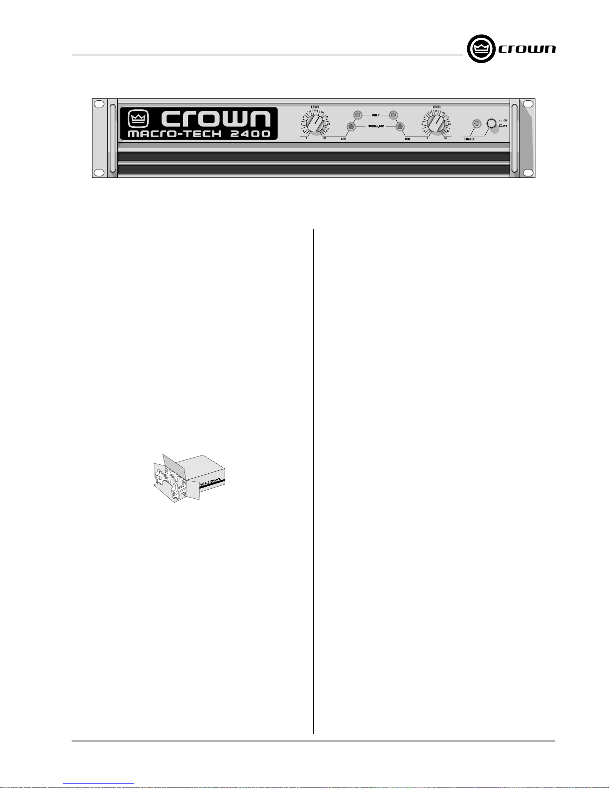
Fig. 1.1 Macro-Tech Amplifier
1 Welcome
Congratulations on your purchase of the renowned
Macro-Tech
amplifiers are designed to provide enormous levels of
pure, undistorted power in a rugged low-profile package—making them
ment. They utilize our patented ODEP® protection
circuitry to
fiers have shut down. And with their PIP expandability,
Macro-Tech amplifiers can be easily customized with
one of our many optional input modules (see Section 8
for a list of available PIP
This manual will help you successfully install and use
your new amplifier. Please read all instructions, warnings and cautions. Be sure to read Sections 3.3.2 and
3.3.3 if you plan to use one of the amplifier’s two mono
modes. Also for your protection, please send in your
warranty registration card today and save your bill of
sale because it is your official proof of purchase.
1.1 Unpacking
Please unpack and inspect your new amplifier for any
damage that may have occurred during transit. If damage is found, notify the transportation company immediately. Only you, the consignee, may initiate a claim for
shipping damage. Crown will be happy to cooperate
fully as needed. Save the shipping carton as evidence
of damage for the shipper’s inspection.
Even if the unit arrived in perfect condition, as most do,
save all packing materials so you will have them if you
ever need to transport the unit. NEVER SHIP THE UNIT
WITHOUT THE FACTORY PACK.
1.2 Features
Macro-Tech amplifiers use cutting edge technology to
deliver the ultimate in power and value for their size,
weight and price. They offer numerous advantages
over conventional designs and provide benefits you
can’t get in amplifiers from any other manufacturer.
Reference Manual
®
professional power amplifier. Macro-Tech
the choice
keep the show going
for pro sound reinforce-
long after other ampli-
™
s
).
Here are some of their many features:
Crown’s Grounded Bridge™ design delivers large voltage
swings without using easily stressed output- transistor
configurations like conventional amplifiers. The results are
lower distortion and superior reliability.
Patented ODEP (Output Device Emulation Protection) cir-
cuitry compensates for overheating and overload to keep
the amplifier working when others would fail.
®
IOC
PIP (Programmable Input Processor) connector accepts
Two mono modes (Bridge-Mono and Parallel-Mono) for
Very low harmonic and intermodulation distortion result in
High damping factor provides superior control over low-
Full protection against shorted outputs, mismatched
Dedicated power supply transformers isolate channels in
Balanced inputs with internal three-position sensitivity
Versatile 5-way binding posts make it easy to connect out-
Ground lift switch isolates the AC power and phone jack
Efficient heat sinks and a self-contained forced-air cooling
Extra rugged, extruded aluminum front panel with ODEP
Mounts in a standard 19-inch (48.3-cm) equipment rack
Three year “No-Fault” full warranty completely protects
(Input/Output Comparator) circuitry immediately
alerts of any distortion exceeding 0.05%, providing dynamic
proof of distortion-free performance
accessories that tailor the amplifier to suit specific applications.
driving a wide range of load impedances.
the best
frequency drivers for a clean, accurate low end.
loads, input/output DC, general overheating, high-frequency overloads and internal faults.
Stereo mode for superb crosstalk characteristics and reliability—each channel is virtually a separate amplifier.
switch and adjustable front-panel level controls.
put wiring.
audio grounds.
system dissipate heat quickly and evenly for extra amplifier protection and greater power output.
and signal presence/IOC indicators for each channel, and
an Enable indicator.
(units can also be stacked).
your investment and guarantees its specifications.
dynamic transfer function
in the industry.
.
Page 7
Page 8
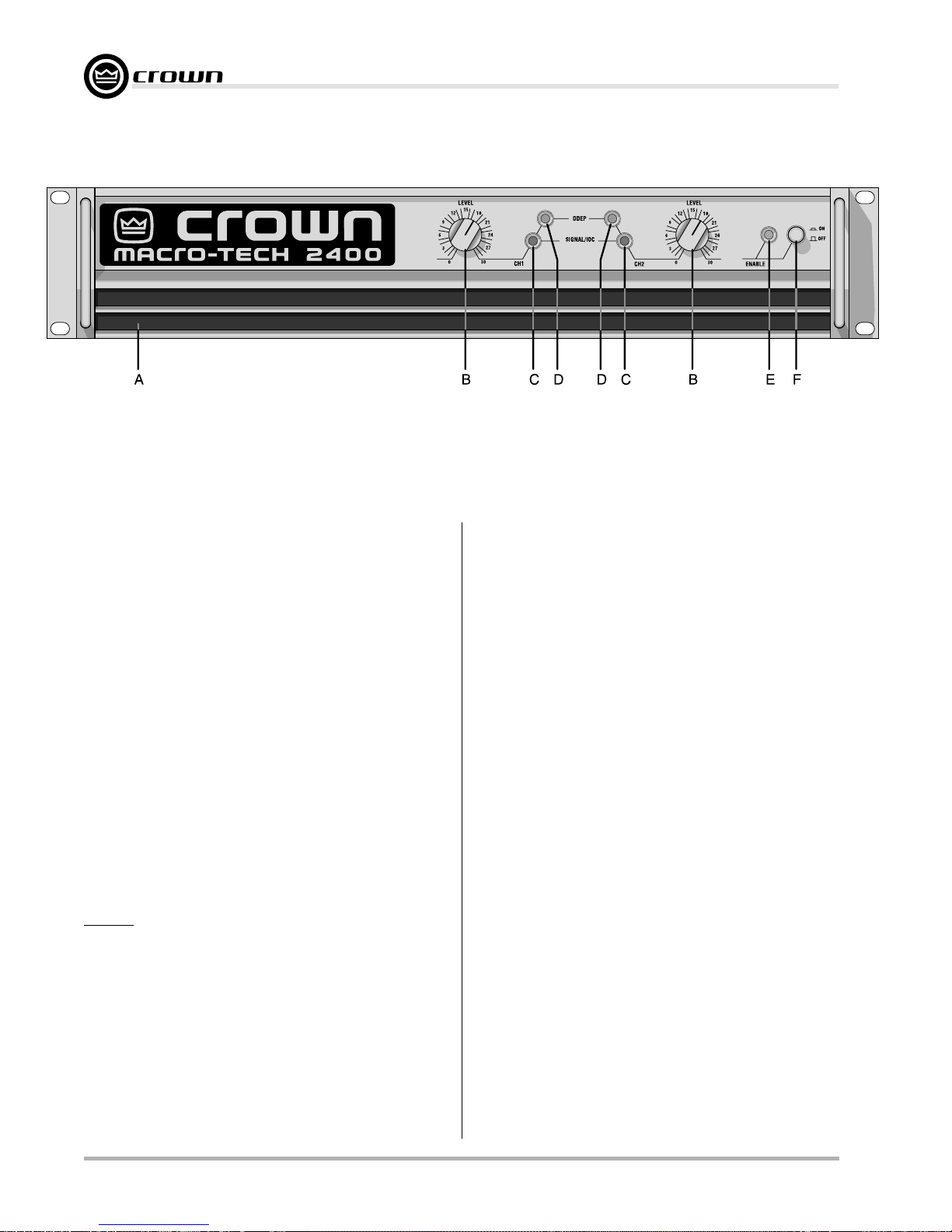
Fig. 2.1 Front Panel Controls & Indicators
2 Controls, Indicators &
Connectors
A. Dust Filters
The dust filters remove large particles from the air
drawn in by the cooling fan. Check the filters regularly
to prevent clogging. The filter elements can be easily
removed for cleaning by gently pulling them away from
the front panel (see Sections 3.2 and 4.5).
B. Level Controls
The output level for each channel is set with these convenient level controls mounted on the front panel. Each
level control has 31 detents for precise adjustment (see
Section 4.4). A security option is available to prevent
tampering (see Section 8.3).
Macro-Tech 600/1200/2400 Power Amplifiers
Emulation Protection) circuitry, these amber indicators
glow brightly to show the presence of reserve thermaldynamic energy. They dim proportionally as energy reserves decrease. In the rare event that energy reserves
are depleted, the indicators turn off and ODEP proportionally limits output drive so the amplifier can safely
continue operating even under severe conditions.
These indicators can also help identify more unusual
operating conditions (see Section 4.2).
E. Enable Indicator
This indicator lights when the amplifier has been “enabled” or turned on, and AC power is available (see
Section 4.2).
C. Signal/IOC Indicators
These green multifunction indicators show signal presence and distortion for each channel. As signal presence indicators, they flash synchronously with the
output audio signals to show their presence. As IOC
(Input/Output Comparator) indicators, they flash
brightly with a 0.1 second hold delay if there is a difference of 0.05% or more between the input and output
signal waveforms. This provides
performance
overload. If an input signal is too large, the indicator for
the affected channel flashes brightly with a 0.5 second
hold delay to show clipping distortion.
nel 2 IOC indicator stays on in Parallel-Mono mode (see
Section 4.2).
. Another IOC function is to indicate input
proof of distortion-free
D. ODEP Indicators
During normal operation of the ODEP (Output Device
Page 8 Reference Manual
Note: The Chan-
F. Enable Switch
This push button is used to turn the amplifier on and off.
When turned on, the output is muted for approximately
four seconds to protect your system from start-up transients. (This delay can be changed. Contact Crown’s
Technical Support Group for details.)
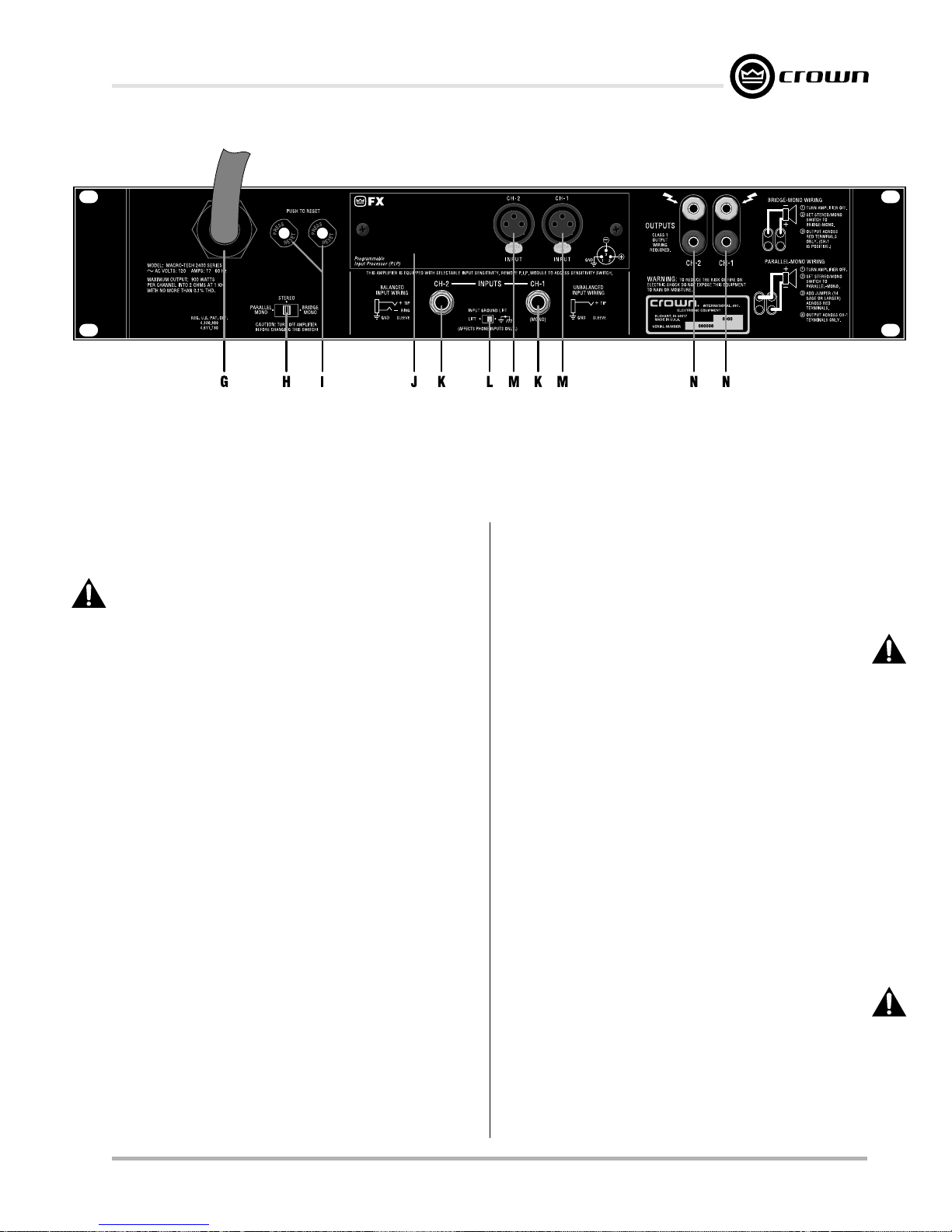
G. Power Cord
The power cord has an appropriate plug for the required voltage. 120 VAC, 60 Hz North American MacroTech 600s and 1200s have 14 AWG line cords and
NEMA 5-15P plugs. Macro-Tech 2400s have 12 AWG
line cords and NEMA 5-20P plugs. International units
are shipped with an appropriate line cord and plug. See
Section 7 for AC power usage.
H. Stereo/Mono Switch
The three operating modes of a Macro-Tech amplifier
Page 9
Macro-Tech 600/1200/2400 Power Amplifiers
Fig. 2.2 Rear Panel Controls & Connectors
(Note: Reset Switches (Item I) only available on the Macro-Tech 2400 model.)
are controlled by this switch. Stereo mode is used for
normal two-channel operation, Bridge-Mono mode is
used to drive a single channel with a load impedance
of at least 4 ohms, and Parallel-Mono mode is used to
drive a single channel with an impedance less than 4
ohms.
Important: Turn off the amplifier before
changing the stereo/mono switch (see Section 3.3).
I. Reset Switches (Macro-Tech 2400 only)
The Macro-Tech 2400 has a back panel Reset switch
for each channel. Each switch resets the circuit breaker
that protects the channel’s power supply from overload.
J. PIP Module
The standard P.I.P.- FX is included with your amplifier. It
provides female three-pin XLR input connectors. A variety of other PIP modules can be used in place of the
P.I.P.-FX. They add additional features that customize
the amplifier for different applications (see Section 8.1
for information on available PIP modules).
Input Sensitivity Switch (not shown)
The three-position input sensitivity switch located inside
the amplifier can be set after removing the PIP module
(J). It is set at the factory to 0.775 volts for standard 1kHz output into 8 ohms. It can also be set to 1.4 volts for
standard 1-kHz output into 8 ohms, or a fixed voltage
gain of 26 dB (see Section 4.4).
sleeve) or unbalanced (tip and sleeve) input signals.
Because they are electrically in parallel with the PIP input connectors, input signals should not be connected
to the phone jacks when certain PIP modules are installed (see Section 3.3.4). The phone jacks can also
be used as “daisy chain” outputs to simplify connecting input signals to multiple amplifiers.
Channel 2 input should NOT be used in either
Bridge Mono or Parallel Mono mode.
Caution: The
L. Ground Lift Switch
This switch isolates or “lifts” the phone jack signal
grounds from the AC power ground. Activating the
switch inserts an impedance between the sleeve of
each phone jack and the unit’s AC ground to help prevent the hum that can result from a ground loop.
M. Balanced XLR Inputs
The factory-installed P.I.P.- FX provides a three-pin female XLR connector for balanced input to each channel. The XLR inputs are connected in parallel with the
amplifier’s phone jack inputs. Because the P.I.P.- FX
does not have any active circuitry, its XLR connectors
can also be used as “daisy chain” outputs to connect
signals from phone jack inputs to multiple amplifiers
(see Section 3.3.4). Caution: The Channel 2 input
should NOT be used in either Bridge Mono or Parallel Mono mode.
K. Balanced Phone Jack Inputs
Balanced ¼-inch phone jack input connectors are provided on the back panel of your amplifier. The phone
jacks can be wired for either balanced (tip, ring and
Reference Manual
N. Output Jacks
A pair of versatile 5-way binding posts is provided for
the output of each channel. The 5-way binding posts
accept banana plugs, spade lugs or bare wire.
Page 9
Page 10
3 Installation
3.1 Mounting
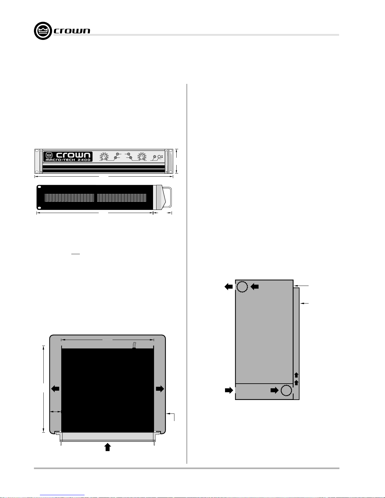
Macro-Tech amplifiers are designed for standard
19-inch (48.3-cm) rack mounting and “stack” mounting
without a cabinet. For more efficient cooling and extra
support in a rack, it is recommended that units be
stacked directly on top of each other.
Important: If the unit will be transported, it should also
be securely supported at the back of the rack.
Macro-Tech 600/1200/2400 Power Amplifiers
When mounting the amplifier in a rack, the side walls of
the rack should be at least 2 inches (5 cm) away from
the chassis as shown in Figure 3.2.
Tip:
An easy way to verify adequate cooling is to observe the ODEP indicators while the amplifier is operating under worst-case conditions. If the indicators dim,
additional cooling is recommended.
LEVEL LEVEL
181512
9
21
24
6
27
3
30
0
19 in
48.3 cm
SIDE VIEW
16 in
40.6 cm
SIGNAL/IOC
ODEP
181512
9
21
ON
24
6
3
0
OFF
27
30
ENABLECH1 CH2
2.5 in
6.35 cm
3.5 in
8.9 cm
Fig. 3.1 Mounting Dimensions
3.2 Cooling
NEVER block the side or front air vents. Macro-Tech
amplifiers do not need to be mounted with space between them. If you must leave open spaces in a rack
for any reason, close them with blank panels to prevent
air from recycling into the front of other amplifiers. Allow
at least 35 cubic feet (1 cubic meter) per minute per
unit for the Macro-Tech 600 and 1200, and at least 45
cubic feet (1.3 cubic meters) per minute per unit for the
Macro-Tech 2400. Additional air flow may be required
when driving low impedance loads at consistently high
output levels. Refer to Section 7 for detailed information
on thermal dissipation.
17 in
43.2 cm
IMPORTANT: Be sure rear of amplifier
is securely mounted to rack.
If your rack has a front door that could block air flow to
the amplifier’s air intakes, you must provide adequate
air flow by installing a grille in the door or by pressurizing the air behind the door. Wire grilles are recommended over perforated panels because they tend to
cause less air restriction. A good choice for pressurizing the air behind a rack cabinet door is to mount a
“squirrel cage” blower inside the rack (Option 1 below).
At the bottom of the rack, mount the blower so it blows
outside air into the space between the door and in front
of the amplifiers, pressurizing the “chimney” behind the
door. This blower should not blow air into or take air out
of the space behind the amplifiers. For racks without a
door, you can evacuate the rack by mounting the
blower at the top of the rack so that air inside the cabinet is drawn out the back (Option 2 below).
AIR
FLOW
BLOWER
(OPTION 2)
EQUIPMENT
RACK
(SIDE VIEW)
FRONT
OF
RACK
DOOR
AIR
FLOW
16 in
40.6 cm
2 in
(5 cm)
MIN.
AMPLIFIER
(TOP VIEW)
AIR FLOW
Fig. 3.2 Top View of a Rack-Mounted Unit
Page 10 Reference Manual
AIR
FLOW
RACK
CABINET
AIR
FLOW
BLOWER
(OPTION 1)
Fig. 3.3 Proper Air Flow in a Rack Cabinet
If the air supply is unusually dusty, you might want to
pre-filter it using commercial furnace filters to prevent
rapid loading of the unit’s own air filter. When needed,
the unit’s filter can be cleaned with mild dish detergent
and water (see Section 4.5).
Page 11
Macro-Tech 600/1200/2400 Power Amplifiers
3.3 Wiring
This section describes the most common ways to install your amplifier in a sound system. The input and
output terminals are located on the back panel. Please
use care when making connections, selecting signal
sources and controlling the output level. The load you
save may be your own! Crown assumes no liability for
damaged loads resulting from careless amplifier use or
deliberate overpowering.
CAUTION: Always remove power from the unit and
turn the level controls off while making or changing
connections.
ers are connected because it reduces the chance of
loud blasts that can cause loudspeaker damage.
Macro-Tech amplifiers may be operated in one of three
modes (Stereo, Bridge-Mono, and Parallel-Mono) by
switching the stereo/mono switch on the back panel.
There are VERY IMPORTANT wiring differences among
these three modes which will be discussed next.
This is very important when loudspeak-
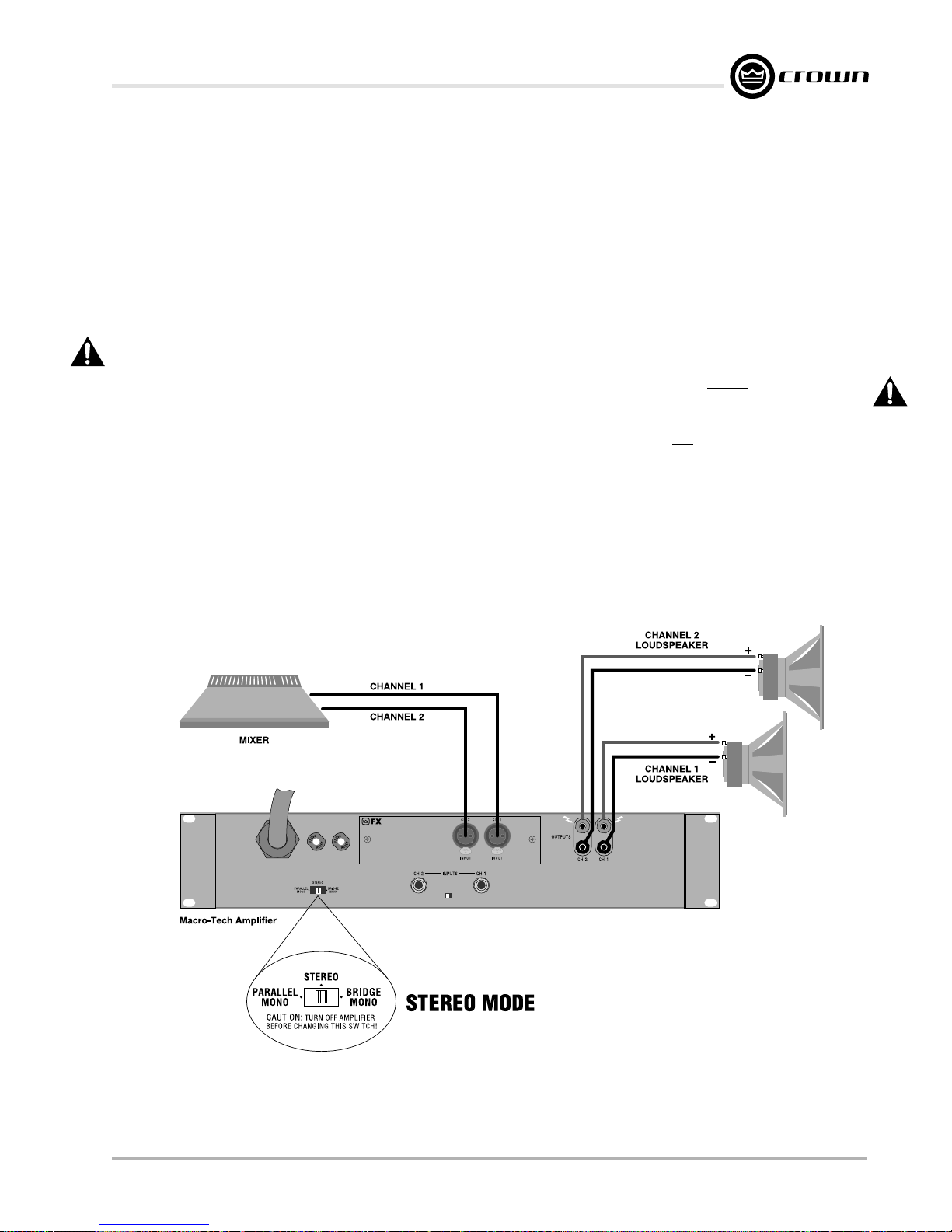
3.3.1 Stereo (Two-Channel) Operation
In Stereo mode, installation is very intuitive: input Channel 1 feeds output Channel 1, and input Channel 2
feeds output Channel 2. To put the amplifier in Stereo
mode, first turn off the amplifier, then slide the stereo/
mono switch to the center position, and properly connect the output wiring as shown in Figure 3.4. A pair of
5-way binding posts is provided for each channel to
facilitate easy connection of loudspeaker wires. Observe correct loudspeaker polarity and be very careful
not to short the two outputs.
CAUTION: In Stereo mode, never parallel the two
outputs by directly tying them together, and never
parallel them with the output of another amplifier.
Such a connection does not result in increased power
output, but may result in overheating and premature
activation of the protection circuitry.
Note: A method for paralleling multiple amplifiers for
fail-safe redundancy is available from Crown’s Technical Support Group.
Reference Manual
Fig. 3.4 Stereo Wiring
Page 11
Page 12
3.3.2 Bridge-Mono Operation
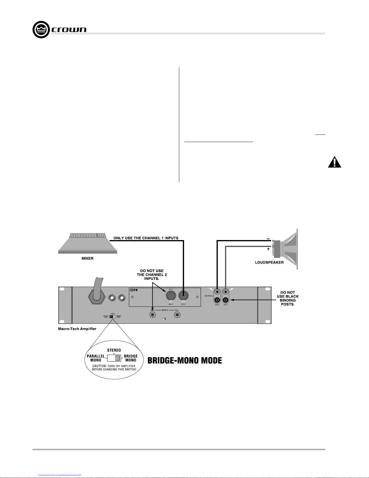
Bridge-Mono mode is intended for driving loads with a
total impedance of 4 ohms or more (If the load is less
than 4 ohms, see Section 3.3.3). Installing the amplifier
in Bridge-Mono mode is very different from the other
modes and requires special attention.
To put the amplifier in Bridge-Mono mode, turn the amplifier off and slide the stereo/mono switch to the right
(as you face the back of the amplifier). Both outputs
receive the signal from Channel 1 with the output of
Channel 2 inverted so it can be bridged with the Channel 1 output. DO NOT USE THE CHANNEL 2 INPUT or
the signal level and quality may be greatly degraded.
Keep the Channel 2 level control turned down completely (counterclockwise).
Note: The input jack and level control of Channel 2 are
Macro-Tech 600/1200/2400 Power Amplifiers
not defeated in Bridge-Mono mode. Any signal fed into
Channel 2 will work against and add to or distort the
signal in Channel 1.
Connect the load across the Channel 1 and 2 red binding posts with the positive lead from the load attaching
to the red post of Channel 1 and the negative lead of
the load attaching to the red post of Channel 2 as shown
in Figure 3.5. THE TWO BLACK BINDING POSTS ARE
NOT USED AND SHOULD NOT BE SHORTED. The
load must be balanced (neither side shorted to
ground).
CAUTION: Be certain all equipment (meters,
switches, etc.) connected to the mono output is balanced. To prevent oscillations, both sides of the line
must be isolated from the input grounds.
Page 12 Reference Manual
Fig. 3.5 Bridge-Mono Wiring
Page 13
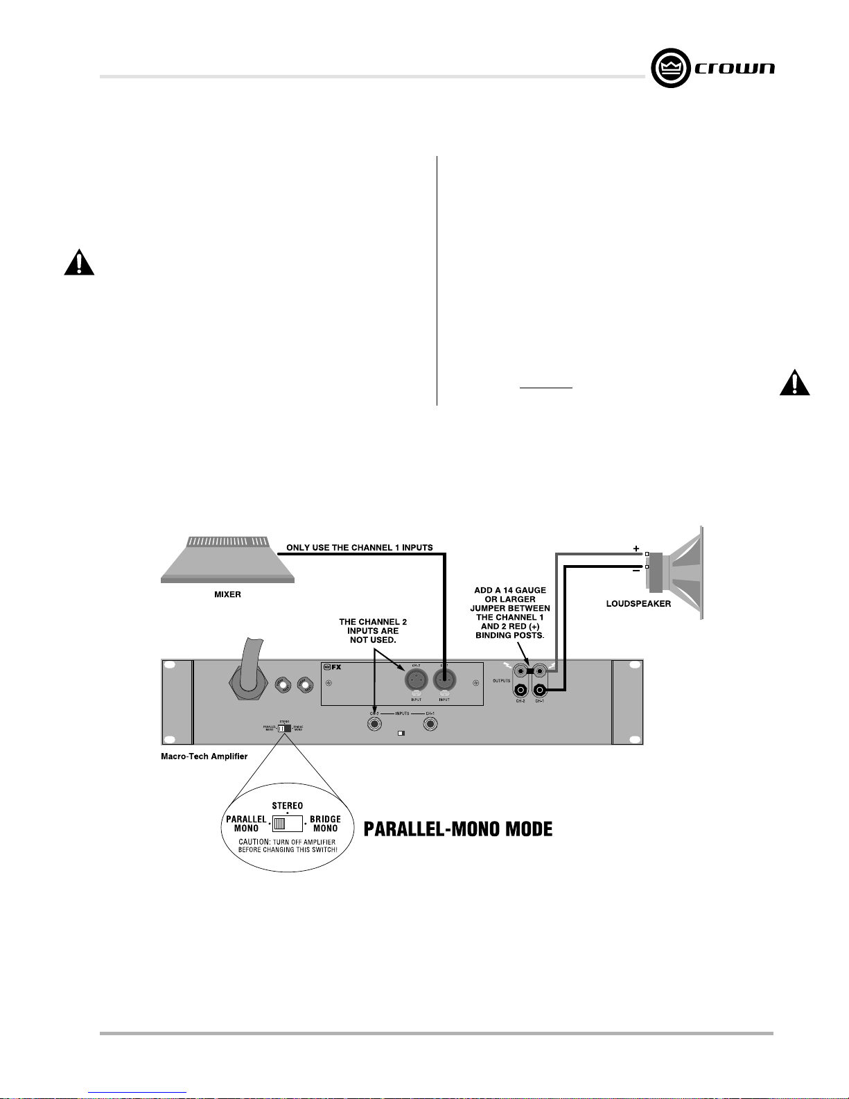
Macro-Tech 600/1200/2400 Power Amplifiers
3.3.3 Parallel-Mono Operation
Parallel-Mono mode is intended for driving loads with a
net impedance of less than 4 ohms. (See Bridge-Mono
if the load is 4 ohms or greater.) Installing the amp in
Parallel-Mono mode is very different from the other
modes and requires special attention.
CAUTION: Do not attempt to operate in Stereo or
Bridge-Mono mode until the Parallel-Mono jumper
is first removed. Failure to do so will result in high
distortion and excessive heating.
To put the amplifier in Parallel-Mono mode, turn it off
and slide the stereo/mono switch to the left (as you face
the back panel). Connect the input signal to Channel 1
only. The Channel 2 input and level control are by-
passed in this mode, so they should not be used.
Note: It is normal for the IOC indicator of Channel 2 to
remain lit in Parallel-Mono mode.
Install a jumper wire between the red binding posts of
both Channel 1 and 2 that is at least 14 gauge in size.
Then, connect the load to the output of Channel 1 as
shown in Figure 3.6. The positive lead from the load
connects to the red binding post of Channel 1 and the
negative lead from the load connects to the black binding post of Channel 1.
CAUTION: Remove the jumper wire before changing to Stereo or Bridge-Mono mode.
Reference Manual
Fig. 3.6 Parallel-Mono Wiring
Page 13
Page 14
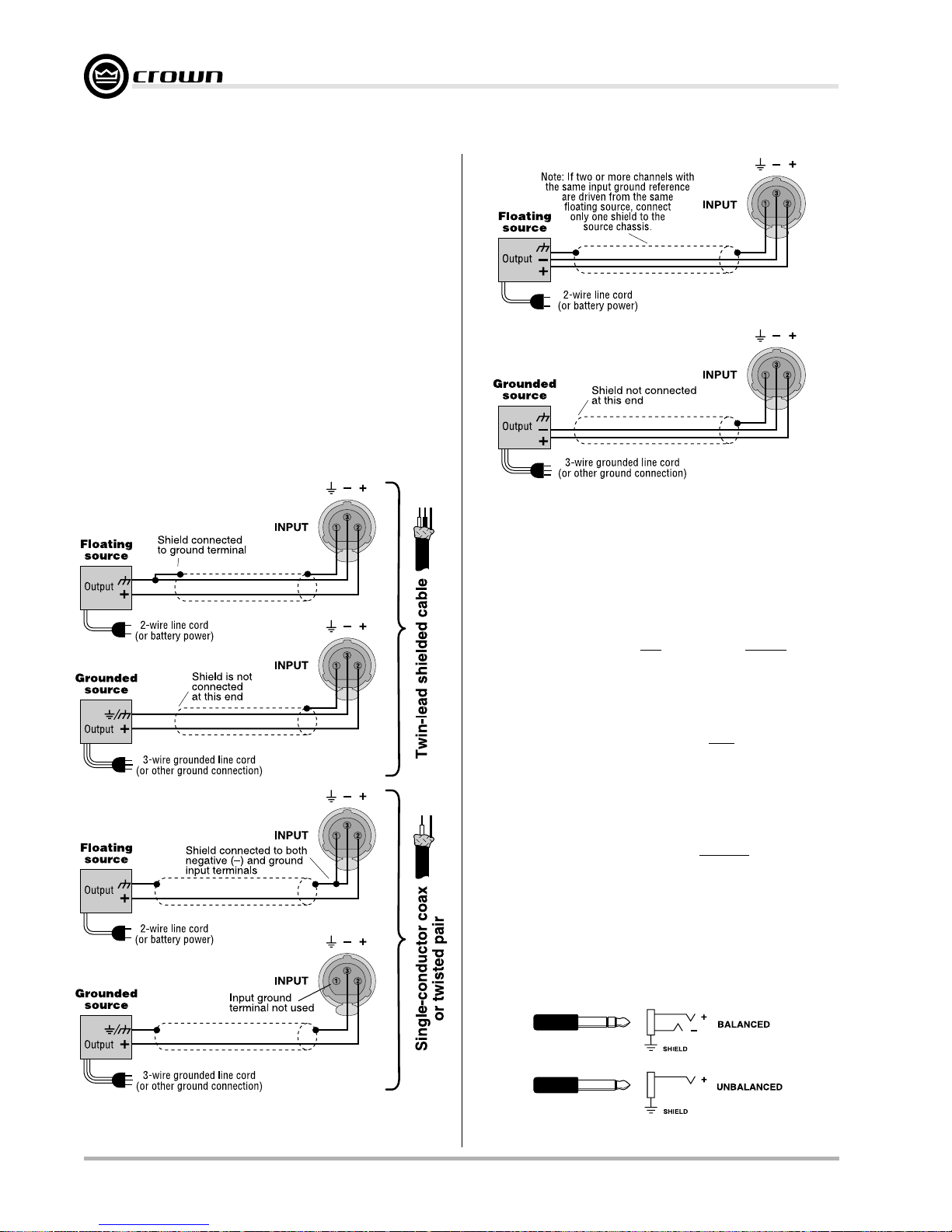
3.3.4 Input Connection
Both the balanced XLR and phone jack inputs have a
nominal impedance of 20 k ohms (10 k ohms with unbalanced wiring) and will accept the line-level output of
most devices. Female three-pin XLR input connectors
are provided on the standard P.I.P.- FX input module
(other PIP modules are described in Section 8.1). Correct input wiring will depend on two factors: (1) whether
the input signals are balanced or unbalanced, and (2)
whether the signal source floats or has a ground reference. Figures 3.7 and 3.8 show the recommended connection techniques for each type of signal source.
The amplifier’s built-in ¼-inch phone jack input connectors can be wired similarly for balanced or unbalanced,
floating or ground-referenced sources. They have a
Macro-Tech 600/1200/2400 Power Amplifiers
Fig. 3.8 Balanced Input Wiring
standard tip-ring-sleeve (TRS) configuration: the tip is
positive (+), the ring is negative (–) and the sleeve is
ground (see Figure 3.9). Wiring for various sources follows the XLR wiring guidelines shown in Figures 3.7
and 3.8.
The phone jacks should not be used as inputs when a
PIP module with active circuitry is installed. The phone
jacks are in parallel with the output of the PIP module,
so an input signal connected to the phone jacks can
feed backwards into the active circuitry of the PIP and
cause undesirable distortion. You can use the phone
jacks for signal input with any of the following PIP modules installed: P.I.P.-FX, P.I.P.-BB, P.I.P.-FMX, P.I.P.- FXQ
and P.I.P.-FPX. All other PIP modules have active circuitry and should not be installed if you plan to connect
input signals to the phone jacks. The phone jacks can
always be used as “daisy chain” outputs to feed postprocessed signals from the PIP to the inputs of other
amplifiers.
Please follow the instruction in Section 3.3.2 and 3.3.3 if
the amplifier will be used in either Bridge-Mono or Parallel-Mono mode. Remember, do not use the Channel 2
input in either of these mono modes.
Fig. 3.7 Unbalanced Input Wiring
Page 14 Reference Manual
Fig. 3.9 Balanced and Unbalanced Phone Plugs
Page 15
Macro-Tech 600/1200/2400 Power Amplifiers
SOLVING INPUT PROBLEMS
Sometimes large infrasonic (subaudible) frequencies
are present in the input signal. These can damage
loudspeakers by overloading or overheating them. To
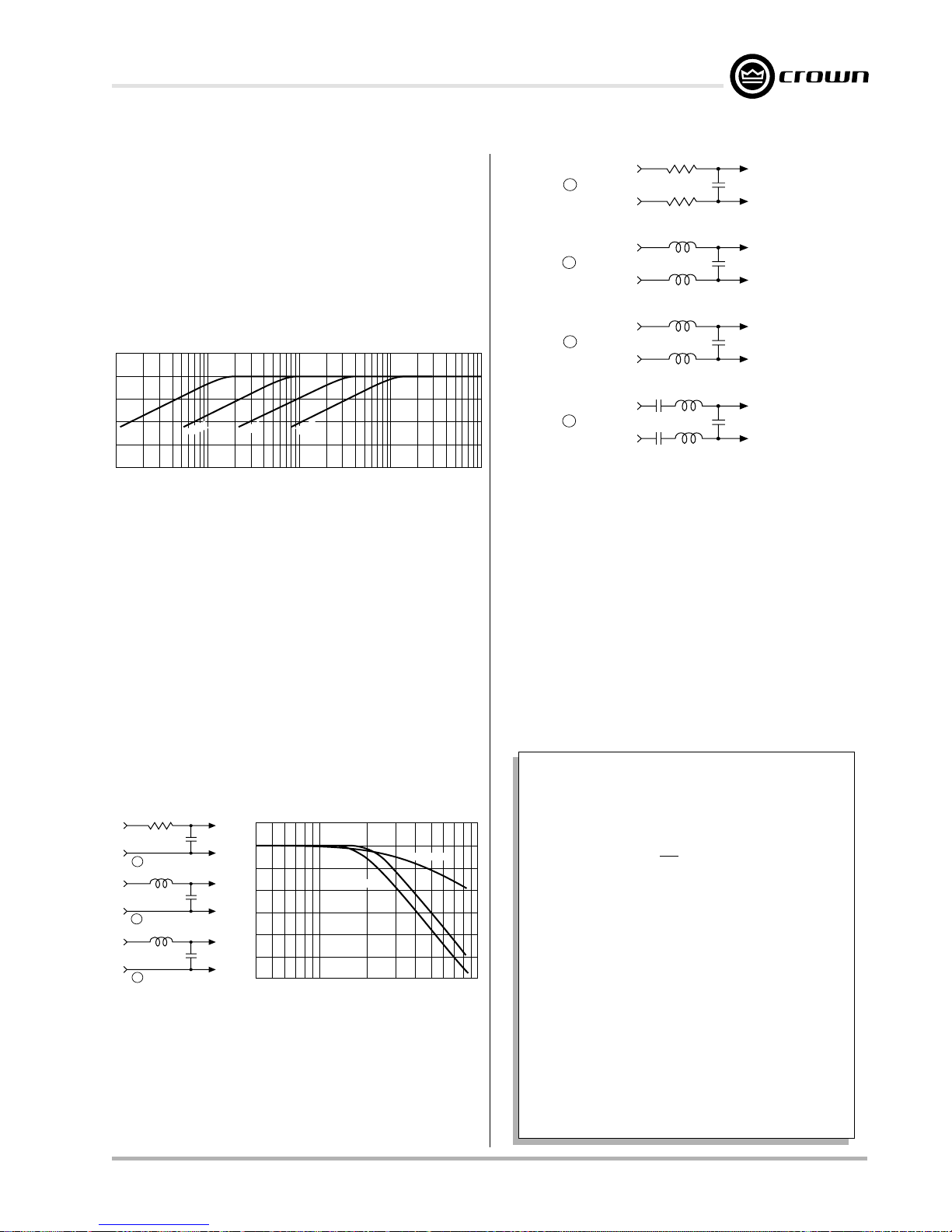
attenuate such frequencies, place a capacitor in series with the input signal line. The graph in Figure 3.10
shows some capacitor values and how they affect the
frequency response. Use only low-leakage paper,
mylar or tantalum capacitors.
dB
0
–5
–10
µ
1 F
–15
1 Hz 10 Hz 100 Hz 1 kHz 10 kHz
.1 F
µ
.05 F
µ
.01 F
Frequency
µ
Fig. 3.10 Infrasonic Filter Capacitors
Another problem to avoid is the presence of large levels of radio frequencies or RF in the input signal. Although high RF levels may not pose a threat to the
amplifier, they can burn out tweeters or other loads that
are sensitive to high frequencies. Extremely high RF levels can also cause your amplifier to prematurely activate its protection circuitry, resulting in inefficient
operation. RF can be introduced into the signal by local
radio stations and from the bias signal of many tape
recorders. To prevent high levels of input RF, install an
appropriate low-pass filter in series with the the input
signal. Some examples of unbalanced wiring for lowpass filters are shown in Figure 3.11.
Ω
910
A
B
C
D
Balanced In
Balanced In
Balanced In
Balanced In
+
–
+
–
+
–
+
–
0.47 Film
0.47 Film
910
1.8 mH
1.8 mH
2.5 mH
2.5 mH
1.8 mH
1.8 mH
.003
µ
F
Ω
.015
µ
F
.018
µ
F
.015
µ
F
+
Balanced Out
–
+
Balanced Out
–
+
Balanced Out
–
+
Balanced Out
–
Fig. 3.12 Balanced RFI Filters
Tip:
The P.I.P.-FX included with your amplifier has plenty
of room on its circuit board for input filters.
A third problem to avoid is hum. The two most common
sources of hum in an audio system are inductive cou-
pling and ground loops.
Inductive coupling can occur when input cables are
subjected to a magnetic field from a power cord or
power transformer. One way to prevent inductive coupling is to lace the input cables together along their
length and route them as far away as possible from
power transformers and power cords. The use of
Input Wiring Tips
1.8 K ohm
Source
600 ohm
R
Source
600 ohm
R
Source
Note: A low source impedance (R) can be
increased to 600 ohms with an appropriate resistor.
.003
A
3.9 mH
.015
µ
B
5 mH
.018
C
To
Amp
Fµ
GND
To
Amp
F
GND
To
Amp
Fµ
GND
4 kHz 10 kHz 40 kHz 100 kHz
Fig. 3.11 Unbalanced RFI Filters
For balanced input wiring use one of the examples in
Figure 3.12. Filters A, B and C correspond to the unbalanced filters above. Filter D also incorporates the infrasonic filter described previously.
Reference Manual
12 dB/octave
Frequency
6 dB/octave
B
C
dB
0
A
–10
1. Use only shielded cable. Cables with
higher density shields are better. Spiral
wrapped shield is not recommended.
2. When using unbalanced lines, keep the
cables as short as possible. Avoid cable
lengths greater than 10 feet (3 meters).
–20
3. Do not run signal cables together with
high-level wiring such as loudspeaker wires or
AC cords. This greatly lessens the chance of
hum or noise being induced into the input
cables.
4. Turn the entire system off before changing
connections. Turn level controls down
completely before powering the system back
up. Crown is not liable for damage incurred
when any transducer or component is
overdriven.
Page 15
Page 16

Macro-Tech 600/1200/2400 Power Amplifiers
shielded pair cable is another effective way to reduce
or eliminate hum resulting from inductive coupling.
Ground loops often result when two or more devices
are improperly grounded. This causes undesirable
stray currents that may produce hum in the output. The
best way to avoid ground loops is to ensure that all system devices are plugged into the same power strip. In
addition, make sure that all cable shields are grounded
at one end only.
Input and output grounds are sometimes tied together
for testing or metering. This can cause feedback oscil-
lation from load current in the test loop. In some systems, even the AC power line may provide this
feedback path. Proper grounding, input isolation and
isolation of common AC devices in the system is good
practice.
3.3.5 Output Connection
Consider the power-handling capacity of your load before connecting it to the amplifier. Crown is not liable for
damage incurred at any time due to overpowering. Fusing loudspeaker lines is highly recommended (see Section 3.3.6). Also, please pay close attention to the
precautions provided in Section 4.1.
Use Good Connectors
1. To prevent possible shorts, do not expose
the loudspeaker cable connectors.
2. Do not use connectors that might accidentally tie two channels together when making or
breaking connections (for example, a standard three-wire stereo phone plug).
3. Connectors that can be plugged into AC
power receptacles should never be used.
4. Connectors with low current-carrying capacity should not be used.
5. Connectors with any tendency to short
should never be used.
resistance increases. This is very important because
the amplifier’s excellent damping factor can easily be
negated by insufficient loudspeaker cables.
Use the nomograph in Figure 3.13 and the procedure
that follows to find the recommended wire gauge (AWG
or American Wire Gauge) for your system.
.0002
R
S
SOURCE
RESISTANCE
(ohms)
.0004
.0006
.001
R
L
40
30
20
15
10
9
8
7
6
5
4
3
2
R
L
LOAD
RESISTANCE
(ohms)
R
DAMPING
FACTOR
20,000
10,000
5,000
2,000
1,000
500
200
100
50
20
10
Example Shown:
R = 8 ohms; R = 0.016 ohms or D.F. = 500;
L
Cable Length = 10 ft.; answer: #8 wire
.002
S
.004
.006
.01
.02
COPPER
(ohms/1000 ft.)
2-COND.
CABLE
(feet)
1
2
5
10
20
50
100
200
500
1000
2000
5000
8000
5000
1000
WIRE
(AWG)
500
#28
100
#26
50
#24
#22
#20
#18
10
#16
#14
5
#12
#10
#8
1
#6
#4
.5
#2
#0
#00
.1
#0000
.05
.01
.04
.06
.1
.2
.4
.6
1
2
5
4
2
6
1
10
20
40
S
HOW TO DETERMINE
APPROPRIATE WIRE GAUGE
It is important to use loudspeaker cables with sufficient
gauge (thickness) for the length being used. The resistance introduced by inadequate loudspeaker cables
will reduce both the output power and the motion control of the loudspeakers. The latter problem occurs because the damping factor decreases as the cable
Page 16 Reference Manual
1.5
1
0.9
0.8
0.7
0.6
0.5
Fig. 3.13 Wire Size Nomograph
Page 17
Macro-Tech 600/1200/2400 Power Amplifiers
1. Note the load resistance of the loudspeakers connected
to each channel of the amplifier. Mark this value on the
“Load Resistance” line of the nomograph.
2. Select an acceptable damping factor and mark it on the
“Damping Factor” line. Your amplifier can provide an excellent damping factor of 1,000 from 10 to 400 Hz in Stereo
mode with an 8-ohm load. In contrast, typical damping factors are 50 or lower. Higher damping factors yield lower distortion and greater motion control over the loudspeakers. A
common damping factor for commercial applications is between 50 and 100. Higher damping factors may be desirable
for live sound, but long cable lengths often limit the highest
damping factor that can be achieved practically. (Under
these circumstances, Crown’s
amplifiers can be monitored and controlled when they are
located very near the loudspeakers.) In recording studios
and home hi-fi, a damping factor of 500 or more is very desirable.
3. Draw a line through the two points with a pencil, and
continue until it intersects the “Source Resistance” line.
4. On the “2-Cond. Cable” line, mark the length of the cable
run.
5. Draw a pencil line from the mark on the “Source Resistance” line through the mark on the “2-Cond. Cable” line,
and on to intersect the “Annealed Copper Wire” line.
6. The required wire gauge for the selected wire length and
damping factor is the value on the “Annealed Copper Wire”
line.
Note: Wire size increases as the AWG gets smaller
7. If the size of the cable exceeds what you want to use,
(1) find a way to use shorter cables, like using the
(2) settle for a lower damping factor, or (3) use more than one
cable for each line. Options 1 and 2 will require the substitution of new values for cable length or damping factor in the
nomograph. For option 3, estimate the effective wire gauge
by subtracting 3 from the apparent wire gauge every time
the number of conductors of equal gauge is doubled. So, if
#10 wire is too large, two #13 wires can be substituted, or
four #16 wires can be used for the same effect.
IQ System
®
is often used so
.
IQ System
SOLVING OUTPUT PROBLEMS
Sometimes high-frequency oscillations occur which
can cause your amplifier to prematurely activate its protection circuitry and result in inefficient operation. The
effects of this problem are similar to the effects of the
RF problem described in Section 3.3.4. To prevent highfrequency oscillations:
1. Lace together the loudspeaker conductors for
each channel; do not lace together the conductors from different channels. This minimizes the
chance that cables will act like antennas and
transmit or receive high frequencies that can
cause oscillation.
2. Avoid using shielded loudspeaker cable.
3. Avoid long cable runs where the loudspeaker
cables from different amplifiers share a common
cable tray or cable jacket.
4. Never connect the amplifier’s input and output
grounds together.
5. Never tie the outputs of multiple amplifiers together.
6. Keep loudspeaker cables well separated from
input cables.
7. Install a low-pass filter on each input line (similar
to the RF filters described in Section 3.3.4).
8. Install input wiring according to the instructions
in Section 3.3.4.
Another problem to avoid is the presence of large sub-
sonic currents when primarily inductive loads are
used. Examples of inductive loads are 70-volt transformers and electrostatic loudspeakers.
Inductive loads can appear as a short circuit at low frequencies. This can cause the amplifier to produce large
low-frequency currents and activate its protection circuitry. Always take the precaution of installing a highpass filter in series with the amplifier’s input when
inductive loads are used. A 3-pole, 18-dB-per-octave
filter with a –3 dB frequency of 50 Hz is recommended
(depending on the application, an even higher –3 dB
frequency may be desirable). Such a filter is described
,
with infrasonic frequency problems in Section 3.3.4.
Another way to prevent the amplifier from prematurely
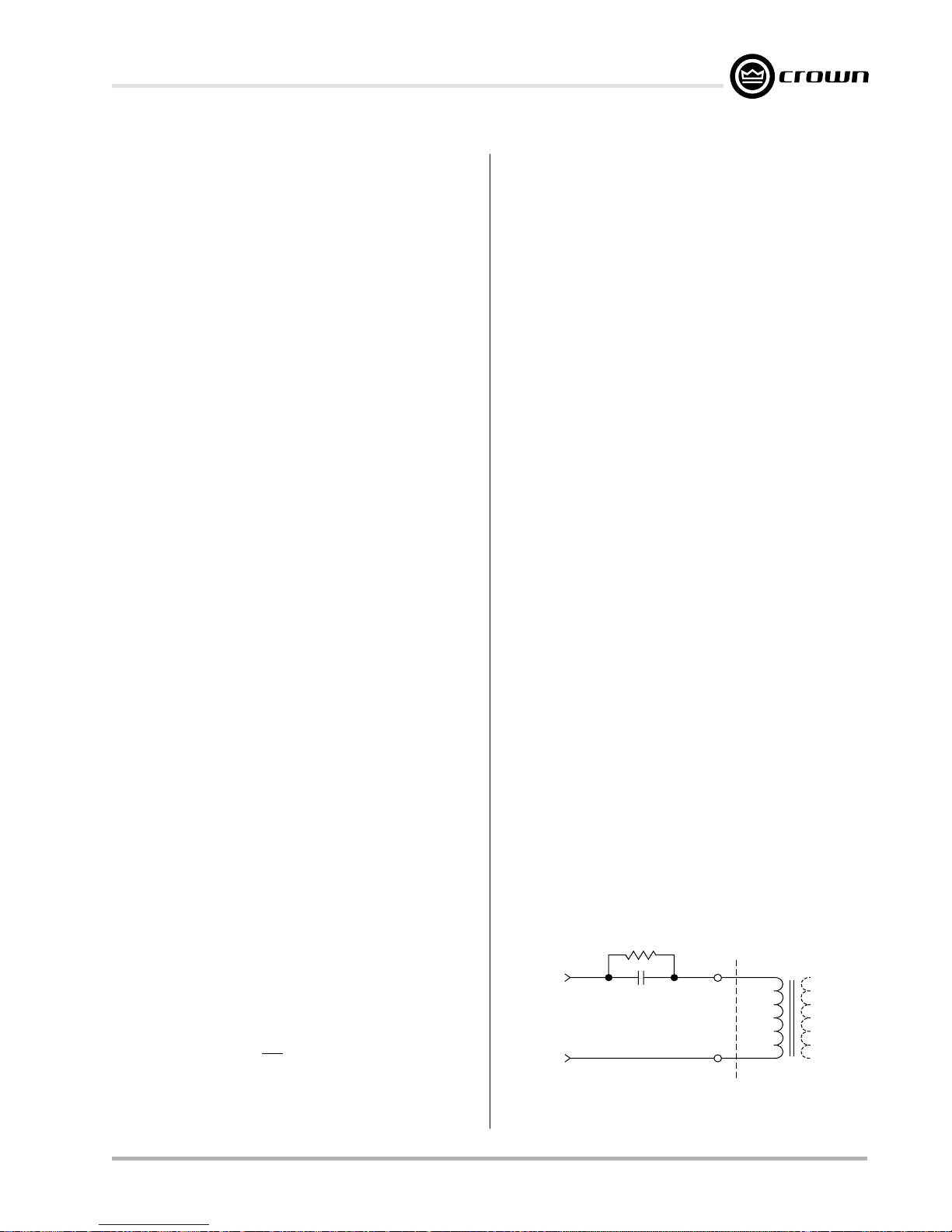
activating its protection systems and to protect inductive loads from large low-frequency currents is to connect a 590 to 708 µF nonpolarized capacitor and
4-ohm, 20-watt resistor in series with the amplifier’s output and the positive (+) lead of the transformer. The
circuit shown below uses components that are available from most electronic supply stores.
4-ohm, 20-watt
Resistor
+
590 to 708 µF Capacitor
From
Amplifier
Output
–
120 VAC, N.P.
Fig. 3.14 Inductive Load (Transformer) Network
+
–
Inductive
Load
Reference Manual
Page 17
Page 18
3.3.6 Additional Load Protection
Macro-Tech amplifiers generate enormous power. If
your loudspeakers do not have built-in protection from
excessive power, it’s a good idea to protect them. Loudspeakers are subject to thermal damage from sustained overpowering and mechanical damage from
large transient voltages. Special fuses can be used to
protect your loudspeakers in both cases.
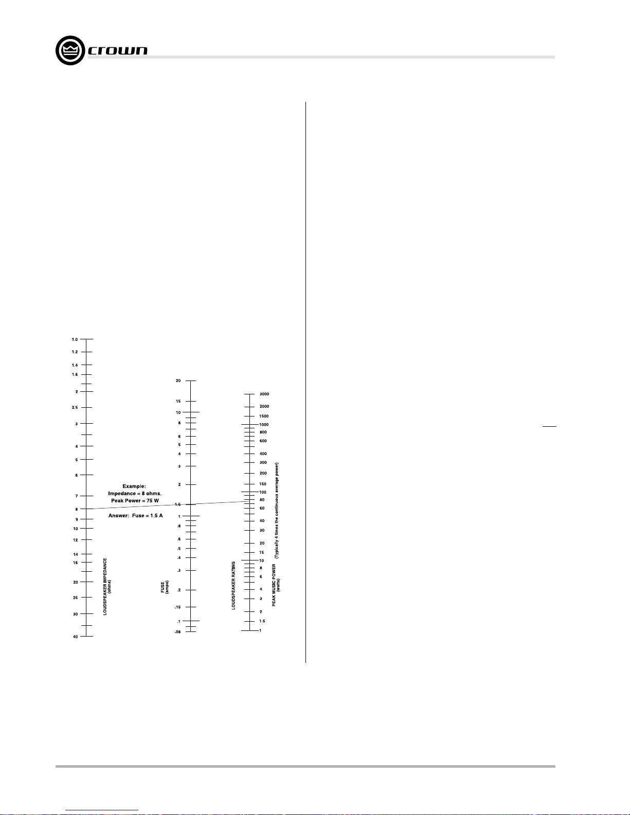
Two different types of fuses are required for thermal protection and voltage protection. Slow-blow fuses are
usually selected to protect loudspeakers from thermal
damage because they are similar to loudspeakers in
the way they respond to thermal conditions over time.
In contrast, high-speed instrument fuses like the
Littlefuse 361000 series are used to protect loudspeakers from large transient voltages. The nomograph in
Figure 3.15 can be used to select the properly rated
fuse for either type of loudspeaker protection.
Macro-Tech 600/1200/2400 Power Amplifiers
There are basically two approaches that can be taken
when installing fuses for loudspeaker protection. A common approach is to put a single fuse in series with the
output of each channel. This makes installation convenient because there is only one fuse protecting the
loads on each output. The main disadvantage of this
approach becomes obvious if the fuse blows because
none of the loads will receive any power.
A better approach is to fuse each driver independently.
This allows you to apply the most appropriate protection for the type of driver being used. In general, lowfrequency drivers (woofers) are most susceptible to
thermal damage and high-frequency drivers (tweeters)
are usually damaged by large transient voltages. This
means that your loudspeakers will tend to have better
protection when the woofers are protected by slow-blow
fuses and high-frequency drivers are protected by highspeed instrument fuses.
Fig. 3.15 Loudspeaker Fuse Nomograph
3.4 AC Power Requirements
All Macro-Tech amplifiers are shipped with an appropriate line cord. When possible, use a power receptacle on a dedicated circuit and always make sure that
it can supply the correct voltage and curent. We do not
recommend operating your amplifier on voltages
greater than 10% above or below the unit’s rated voltage. For example, if your amplifer is rated for 120 VAC,
the line voltage should not exceed 132 VAC. See Section 7 for power requirements under a variety of conditions.
All specifications in this manual were measured using
120 VAC, 60 Hz power, unless otherwise noted. Specifications were derived using a voltage that is accurate
to within 0.5% with THD less than 1.0% under all testing
conditions. Performance variations can occur at other
AC voltages and frequencies. In addition, line regulation problems directly affect the output power from the
amplifier.
Page 18 Reference Manual
Page 19
Macro-Tech 600/1200/2400 Power Amplifiers
4 Operation
4.1 Precautions
Macro-Tech amplifiers are protected from internal and
external faults, but you should still take the follow precautions for optimum performance and safety:
1. Improper wiring for Stereo, Bridge-Mono and
Parallel-Mono modes can result in serious operating difficulties. Refer to Section 3.3 for details.
2. WARNING: Do not change the position of the
stereo/mono switch unless the amplifier is first
turned off.
3. CAUTION: In Parallel-Mono mode, a jumper is
used between the red (+) Channel 1 and 2 output
binding posts. Be sure to remove this jumper for
Stereo or Bridge-Mono mode, otherwise high
distortion and excessive heating will definitely
occur. Check the stereo/mono switch on the back
panel for proper position.
4. Turn off the amplifier and unplug it from the AC
mains before removing the PIP card.
5. Use care when making connections, selecting signal sources and controlling the output level. The
load you save may be your own.
6. Do not short the ground lead of an output cable to
the input signal ground. This may form a ground
loop and cause oscillations.
7. Operate the amplifier from AC mains of not more
than 10% variation above or below the selected line
voltage and only the specified line frequency.
8. Never connect the output to a power supply output, battery or power main. Such connections
may result in electrical shock.
9. Tampering with the circuitry by unqualified personnel, or making unauthorized circuit changes invalidates the warranty.
Remember: Crown is not liable for damage that results
from overdriving other system components.
4.2 Indicators
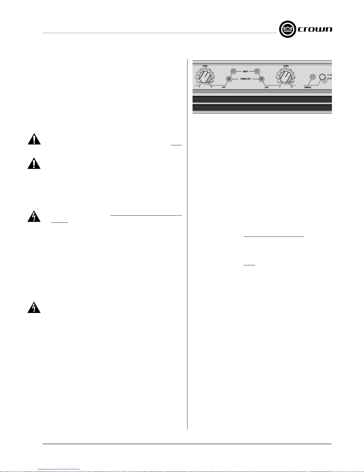
The amber Enable indicator is provided to show that
the amplifier has been turned on (or enabled), and that
its low-voltage power supply and forced-air cooling system are working. It does not indicate the status of the
high-voltage power supplies. For example, the Enable
indicator will remain lit during unusual conditions that
would cause the amplifier’s protection systems to put a
Fig. 4.1 Indicators
high-voltage power supply in “standby” mode (see
Section 4.3).
The amber ODEP indicators confirm the normal operation of Crown’s patented Output Device Emulation
Protection circuitry. During normal operation, they glow
brightly to show the presence of reserve thermal-dynamic energy. They dim proportionally as the energy
reserve decreases. In the rare event that there is no
reserve, the indicators turn off and ODEP proportionally limits the drive level of the output stages so the amplifier can continue safe operation even when
conditions are severe. (For a more detailed description
of ODEP, see Section 4.3.1.)
The ODEP indicator for the affected channel will turn off
if a high-voltage power supply is put in “standby” mode,
a high-voltage power supply fuse (or breaker) blows,
or a transformer activates its thermal protection circuitry
(see Section 4.3.2). Both ODEP indicators turn off if the
amplifier loses AC power, the power switch is turned off
or the low-voltage power supply fuse blows.
The green Signal/IOC indicators show signal presence, distortion and input overload. As signal presence
indicators, they flash with normal intensity in sync with
the output audio signals. As IOC (Input/Output Comparator) indicators, they flash brightly if there is any difference between the input and output signal waveforms
greater than 0.05%. Because transient distortion happens quickly, a 0.1 second “hold delay” keeps the indicators on long enough to be easily noticed. The IOC
function essentially provides
formance
brightly with a 0.5 second hold delay to show that an
input signal is too large and must be clipped at the input.
. As input overload indicators, they flash
Note: The Channel 2 IOC indicator will remain lit
proof of distortion-free per-
when running in Parallel-Mono mode.
Under abnormal conditions where one of the amplifier’s
high-voltage power supplies is temporarily put in
standby mode, the Signal/IOC indicators will stay on
with full brightness. They will resume normal operation
when the amplifier is no longer in standby mode.
Reference Manual
Page 19
Page 20
Macro-Tech 600/1200/2400 Power Amplifiers
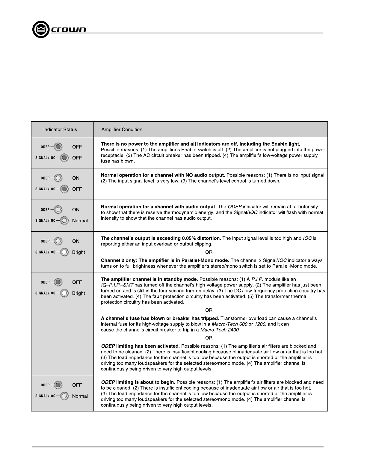
The table in Figure 4.2 shows the possible states for the
ODEP and Signal/IOC indicators. It also describes the
conditions that may be associated with the different indicator states. The Enable indicator will be off with the
first indicator state, “There is no power to the amplifier.”
All other conditions in the table will occur with the En-
able indicator turned on. It is important to note the possible states of the indicators in the rare event that you
experience a problem. This can greatly aid in determining the source of problems. Please contact your local Crown representative or our Technical Support
Group for futher assistance.
Fig. 4.2
Page 20 Reference Manual
Macro-Tech ODEP
and Signal/
IOC
Indicator States
Page 21

Macro-Tech 600/1200/2400 Power Amplifiers
4.3 Protection Systems
Macro-Tech amplifiers provide extensive protection and
diagnostics capabilities. Protection systems include
ODEP, “standby” mode, fuses (or breakers), and special thermal protection for the unit’s transformers.
4.3.1 ODEP
Crown invented ODEP to solve two long-standing problems in amplifier design: to prevent amplifier shutdown
during demanding operation and to increase the efficiency of the output circuitry.
To do this, Crown established a rigorous program to
measure the
transistor before installing it in an amplifier. Next, Crown
designed intelligent circuitry to simulate the instantaneous operating conditions of those output transistors.
Its name describes what it does: Output Device Emulation Protection or ODEP. In addition to simulating the
operating conditions of the output transistors, it also
compares their operation to their known SOA. If it sees
that more power is about to be asked of them than they
are capable of delivering under the present conditions,
ODEP immediately limits the drive level until it falls within
the SOA. Limiting is proportional and kept to an absolute minimum—only what is required to prevent output
transistor damage.
This level of protection enables Crown to increase output efficiency to never-before-achieved levels while
greatly increasing amplifier reliability.
The on-board intelligence is monitored in two ways.
First, the front panel ODEP indicators show whether the
amplifier is functioning correctly or if ODEP is limiting
the drive level. Second, ODEP data is fed to the back
panel PIP connector so advanced PIP modules like the
IQ-PIP can use it to monitor and control the amplifier.
With ODEP, the show keeps going because you get the
maximum power with the maximum protection.
4.3.2 Standby Mode
At the heart of the protection systems is the standby
mode which removes power from the high-voltage supplies to protect the amplifier and connected loads. The
standby mode can be identified using the indicator
table in Figure 4.2.
Standby mode can be activated in several situations.
First, if dangerous subsonic frequencies or direct current (DC) is detected in the amplifier’s output, the unit
will activate its DC/low-frequency protection circuitry
and put the affected channels in standby. This protects
safe operating area
(SOA) of each output
the loads and prevent oscillations. The unit resumes
normal operation as soon as the amplifier no longer
detects dangerous low frequency or DC output. Although it is extremely unlikely that you will ever activate
the amplifier’s DC/low-frequency protection system, improper source materials such as subsonic square
waves or input overloads that result in excessively
clipped input signals can activate this system.
The amplifier’s fault protection system will put an am-
plifier channel in standby mode in rare situations where
heavy common-mode current is detected in the
channel’s output. The amplifier should never output
heavy common-mode current unless its circuitry is
damaged in some way, and putting a channel in
standby mode helps to prevent further damage.
The amplifier’s transformer thermal protection circuitry is activated in very unusual circumstances where
the unit’s transformer temperature rises to unsafe levels. Under these abnormal conditions, the amplifier will
put the channel of the affected transformer in standby
mode. The amplifier will return to normal operation after
the transformer cools to a safe temperature. (For more
information on transformer thermal protection, refer to
the following section.)
4.3.3 Transformer Thermal Protection
All Macro-Tech amplifiers have transformer thermal protection. It protects the power supplies from damage under the rare conditions of transformer temperatures
rising too high. A thermal switch embedded in each
transformer removes power to the channel if there is
excessive heat. The switch automatically resets when
the transformer cools to a safe temperature.
It is extremely unlikely that you will ever see a
Macro-Tech amplifier activate transformer thermal protection as long as it is operated within rated conditions
(see Section 6,
Specifications
). One reason is that
ODEP keeps the amplifier working under very severe
conditions. Even so, higher than rated output levels,
excessively low impedance loads and unreasonably
high input signals can generate more heat in the transformer than in the output devices. These conditions can
overheat the transformer and activate its protection system.
Macro-Tech amplifiers are designed to keep working
under conditions where other amplifiers would fail. But
even when the limits of a Macro-Tech amplifier are exceeded, it will still protect itself—and your investment—
from damage.
Reference Manual
Page 21
Page 22
Macro-Tech 600/1200/2400 Power Amplifiers
4.3.4 Fuses and Circuit Breakers
The power supplies of the Macro-Tech 600 and 1200
are protected by fuses. The power supplies of the
Macro-Tech 2400 are protected by circuit breakers.
With rated loads and output levels, the fuses (or circuit
breakers) should only shut down the amplifier in the
rare instance of a catastrophic failure. Other protection
systems like ODEP keep the amplifier operational under most other severe conditions. The fuses (or circuit
breakers) can also shut down the amplifier in cases
where extremely low-impedance loads and high output
levels result in current draw that exceeds their rating.
Again, this should only be possible when operating
outside rated conditions
, such as when the amplifier is
used to drive a 1-ohm load in Stereo mode, or when a
signal overloads the input and is clipped severely.
All 120 VAC, 60 Hz units and all Macro-Tech 2400s have
a separate fuse for the low-voltage power supply and
cooling fan. All units have separate fuses or breakers
for the high-voltage power supplies.
Macro-Tech amplifiers do not blow their fuses or trip
their breakers unless something is wrong. In the rare
event that an internal fuse blows, please refer the unit
to a qualified technician. If a breaker in a Macro-Tech
2400 trips, try to identify and correct the problem before resetting the breakers with the back panel Reset
switches. If the problem persists, refer the unit to a
qualified technician.
4.4 Controls
The Enable switch is located on the front panel so you
can easily turn the amplifier on and off. If you ever need
to make any wiring or installation changes, don’t forget
to disconnect the power cord. The six steps listed next
should be followed whenever you turn on the amplifier:
4. After the mute delay, turn up the level of your audio
source to the maximum desired level.
5. Turn up the level controls of the amplifier until the
maximum desired sound level is achieved.
6. Turn down the level of your audio source to its
normal range.
For ease of use, the level controls are also located on
the front panel. Each control has 31 detents for accurate repeatability. To prevent tampering with these controls, the Level Control Security Kit is available (see
Section 8.3).
Note: In Bridge-Mono and Parallel-Mono
modes, turn down the Channel 2 level control and only
use the Channel 1 control.
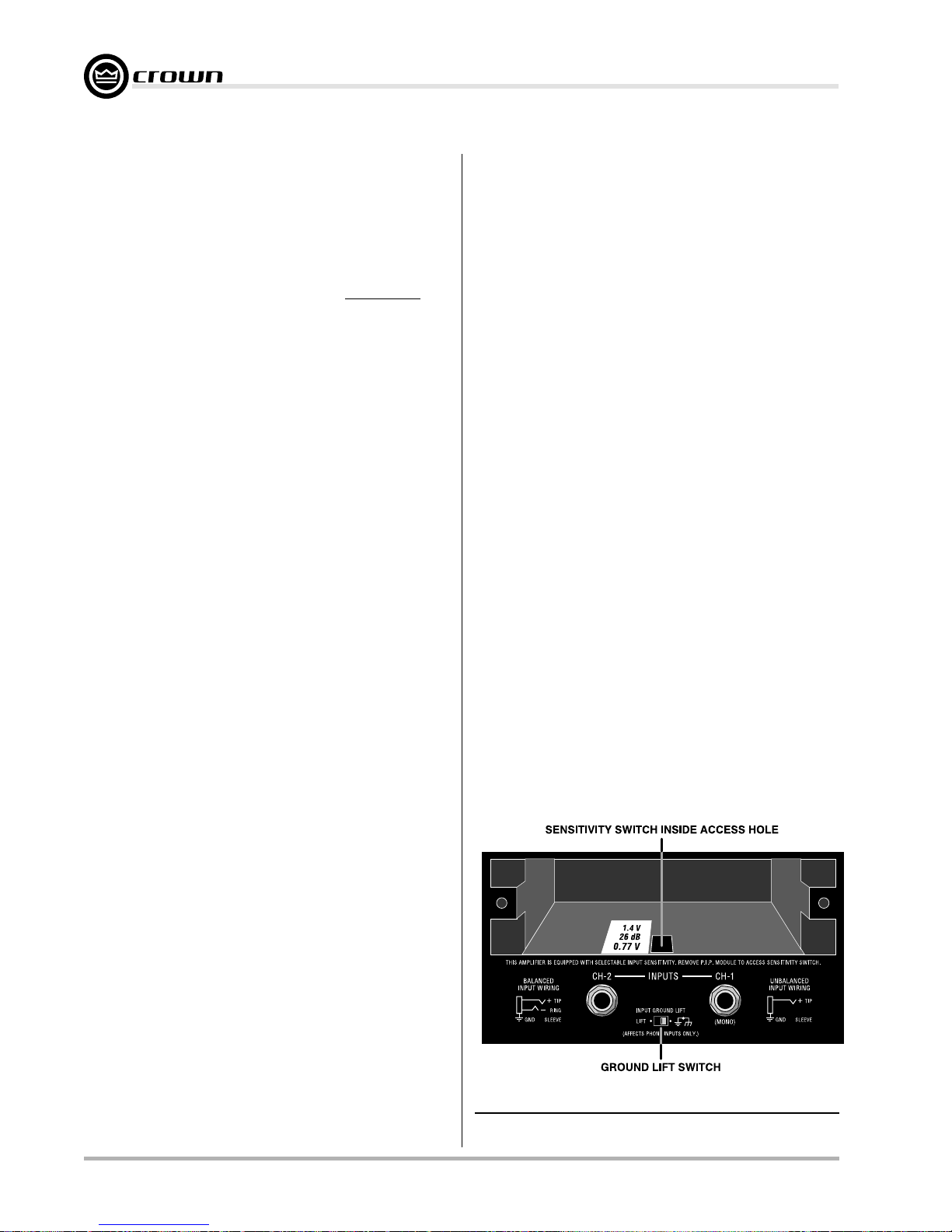
The input sensitivity switch is located inside the back
panel of the amplifier. It is factory-set to 0.775 volts for
standard 1-kHz power into 8 ohms. It can be switched
either to 1.4 volts for standard 1-kHz power output, or
to a fixed voltage gain of 26 dB. When set to 26 dB
gain, the input sensitivity is 2.2 volts for the Macro-Tech
600, 2.6 volts for the Macro-Tech 1200 and 3.1 volts for
the Macro-Tech 2400.
How to change the input sensitivity:
1. Turn off the amplifier and disconnect its power cord
from the AC mains power receptacle.
2. Remove the PIP module (two screws).
3. Locate the sensitivity switch access hole inside the
chassis opening as shown in Figure 4.3. It is
located just above the phone jack inputs.
4. Set the switch to the desired position noted on the
label for the access hole. The position toward the
front panel sets the sensitivity to 1.4 volts for
1. Turn down the level of your audio source. For
example, set your master mixer’s volume to –∞.
2. Turn down the level controls of the amplifier (if they
are not already down).
3. Turn on the Enable switch. The Enable indicator
beside the switch should glow. During the four
second mute delay which immediately follows, the
Signal/IOC indicators will flash unpredictably and
the ODEP LEDs will stay off. After the mute delay,
the ODEP indicators should come on with full
brilliance and the Signal/IOC indicators should
function normally (remain off if no signal is present;
flash if a signal is present). Remember, the Channel
2 Signal/IOC indicator will remain on if the amplifier
is in Parallel-Mono mode.
Page 22 Reference Manual
Fig. 4.3 Input Sensitivity and Ground Lift Switches
*Factory setting for international versions is 1.4 V.
Page 23

Macro-Tech 600/1200/2400 Power Amplifiers
standard 1-kHz power, the middle position provides
26 dB gain, and the back position sets the
sensitivity to 0.775 volts for standard 1-kHz power.
5. Replace the PIP module and reconnect the power
to the amplifier.
The Ground Lift switch is located on the back panel
and can provide isolation between the input signal
grounds and the AC (chassis) ground. It affects only
the phone jack inputs and has no affect on the PIP module input connectors. Sliding the switch to the left isolates or “lifts” the grounds by placing an impedance
between the sleeve of each input phone jack and the
AC power ground.
The noninverted and inverted signal lines for the PIP
module are connected in parallel with the corresponding lines of the phone jack inputs. The input signal
grounds are not paralleled. Specifically, XLR pins 2 and
3 are connected in parallel with the tip and ring of the
corresponding phone jack. However, pin 1 of the XLR
is not connected in parallel with the sleeve of the phone
jack. This makes it possible for a PIP module to handle
its own signal grounds independently.
The Macro-Tech 2400 has back panel Reset switches
that are used to reset the breakers that protect the highvoltage power supplies from overload. If a breaker trips,
the IOC indicator for the affected channel will turn on
(see Figure 4.2).
4.5 Filter Cleaning
Dust filters are provided on the air intakes to the cooling
system (see Figure 2.1). If these filters become
clogged, the unit will not cool as efficiently as it should
and may produce output levels that are lower than normal due to high heat sink temperature.
To clean, remove each of the filter elements by gently
pulling them away from the front panel. Clean with mild
dishwashing detergent and warm water. Replacement
filters may be ordered from the factory.
Dust filters are not 100% efficient—depending on the
local environment, the internal heat sinks of the amplifier will benefit from periodic cleaning by a qualified
technician. Internal cleaning information is available
from our Technical Support Group.
Reference Manual
Page 23
Page 24

Macro-Tech 600/1200/2400 Power Amplifiers
5 Technical Information
5.1 Overview
Your Macro-Tech amplifier incorporates several new
technological advancements including real-time computer simulation of output transistor stress, low-stress
output stages, an advanced heat sink embodiment and
the Programmable Input Processor (PIP) expansion
system.
Custom circuitry is incorporated to limit temperature
and current to safe levels, making it highly reliable and
tolerant of faults. Unlike many lesser amplifiers, it can
operate at its voltage and current limits without self-destructing.
Real-time computer simulation is used to create an analogue of the junction temperature of the output transistors (hereafter referred to as “output devices”). Current
is limited only when the device temperature becomes
excessive (and by the minimum amount required). This
patented approach is called Output Device Emulation
Protection (or ODEP). It maximizes the available output
power and protects against overheating—the major
cause of device failure.
The amplifier is protected from all common hazards that
plague high-power amplifiers including shorted, open
or mismatched loads; overloaded power supplies, excessive temperature, chain-destruction phenomena,
input overload and high-frequency blowups. The unit
protects loudspeakers from input and output DC, as
well as turn-on and turn-off transients.
The four-quadrant topology used in a Macro-Tech
grounded output stages is called the
This patented topology makes full use of the power supplies providing peak-to-peak voltages to the load that
are twice the voltage seen by the output devices (see
Figure 5.1).
As its name suggests, the Grounded Bridge topology
is referenced to ground. Composite devices are constructed to function as gigantic NPN and PNP devices
to handle currents which exceed the limits of available
devices. Each output stage has two composite NPN
devices and two composite PNP devices.
The devices connected to the load are referred to as
“high-side NPN and PNP” and the devices connected
to ground are referred to as “low-side NPN and PNP.”
Positive current is delivered to the load by increasing
conductance simultaneously in the high-side NPN and
low-side PNP stage, while synchronously decreasing
conductance of the high-side PNP and low-side NPN.
Grounded Bridge
The two channels may be used together to double the
voltage (Bridge-Mono) or the current (Parallel-Mono)
presented to the load. This feature gives you flexibility
to maximize the power available to the load.
A wide bandwidth, multiloop design is used for stateof-the-art compensation. This produces ideal behavior
and results in ultra-low distortion values.
Aluminum extrusions have been widely used for heat
sinks in power amplifiers due to their low cost and reasonable performance. However, measured on a wattsper-pound or watts-per-volume basis, the extrusion
technology doesn’t perform nearly as well as the heat
sink technology developed for Macro-Tech amplifiers.
Our heat sinks are fabricated from custom convoluted
fin stock that provides an extremely high ratio of area to
volume, or area to weight. All power devices are
mounted directly to massive heat spreaders that are
electrically at the Vcc potential. Electrifying the heat
spreaders improves thermal performance by eliminating the insulating interface underneath the power devices. The chassis itself is even used as part of the
thermal circuit to maximize utilization of the available
cooling resources.
5.2 Circuit Theory
Each channel is powered by its own power transformer
T100 or T200. Both channels share a common low-voltage transformer TF-1. The secondary output of T100 is
full-wave rectified by D109 and is filtered by a large
computer-grade capacitor. D104 through D107 provide
boosted voltage to power LVAs and predrivers. A ther-
’s
mal switch embedded in each transformer protects it
.
from overheating.
The low-voltage transformer TF-1 uses a separate winding on the fan motor. The TF-1 output is rectified by diodes D1, D2, D3 and D4 to generate an unregulated 24
volts. Monolithic regulators U1 and U2 provide a regulated ±15 volts.
5.2.1 Stereo Operation
For simplicity, the discussion of Stereo operation will
refer to one channel only. Mono operation will be discussed later.
Please refer to the block diagram in Figure 5.1 and the
schematics provided at the back of this manual.
The input signal at the phone jack passes directly into
the balanced gain stage (U104-C and U104-D). When
the PIP module is used, the input signal first passes
through the PIP’s circuitry and then to the balanced gain
stage.
Page 24 Reference Manual
Page 25
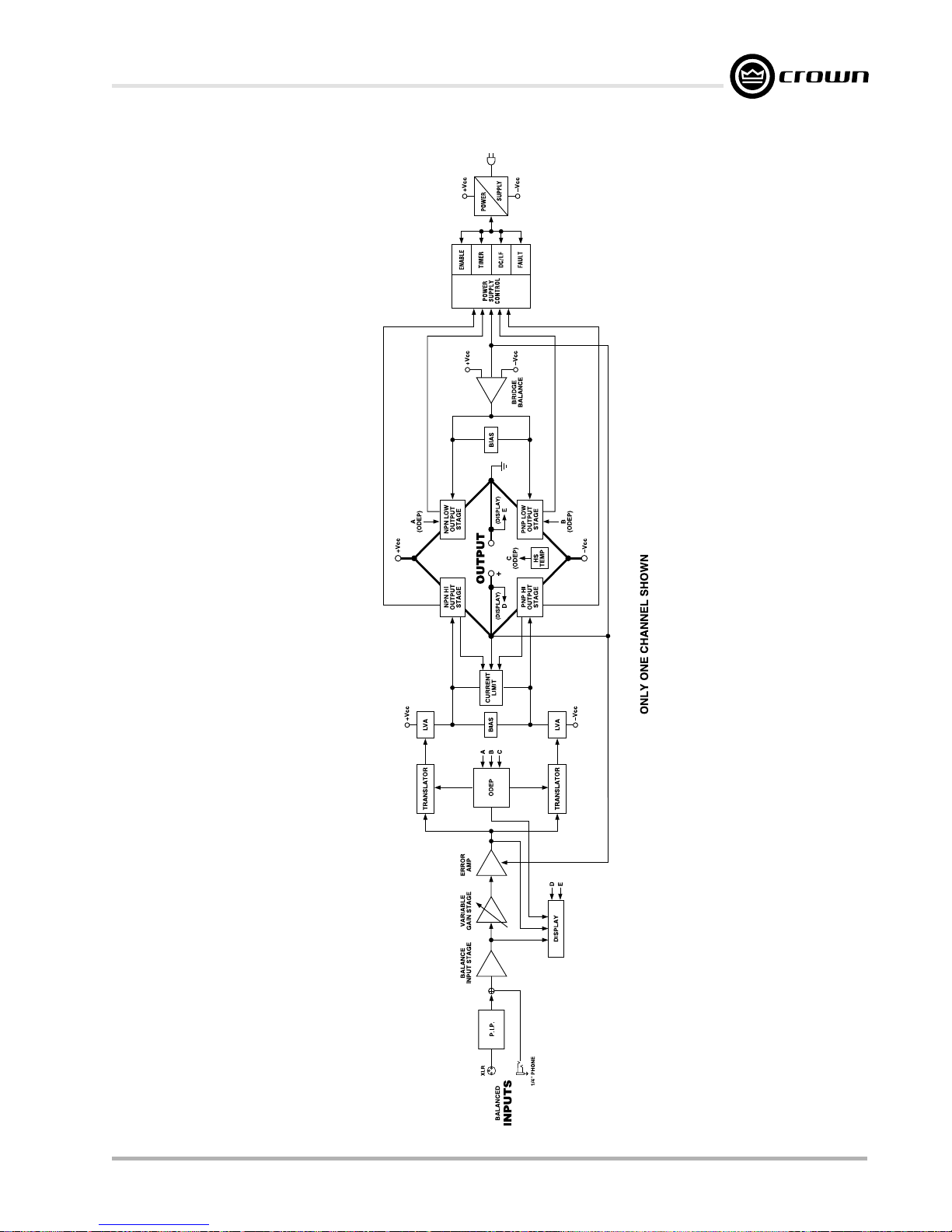
Macro-Tech 600/1200/2400 Power Amplifiers
Reference Manual
Fig. 5.1 Circuit Block Diagram
Page 25
Page 26

Macro-Tech 600/1200/2400 Power Amplifiers
The balanced gain stage (U104-C and U104-D) causes
balanced to single-ended conversion using a difference amplifier. From there, gain can be controlled with
a potentiometer. The error amp (U104-A) amplifies the
difference between the output signal and the input signal from the gain pot, and drives the voltage translator
stage.
From the error amp U104-A, the voltage translator stage
channels the signal to the Last Voltage Amplifiers (LVAs)
depending on the signal polarity. The +LVA (Q104 and
Q105) and the –LVA (Q110 and Q111), with their pushpull effect through the bias servo Q318, drive the fully
complementary output stage.
The bias servo Q318 is thermally coupled to the heat
sink, and sets the quiescent bias current in the output
stage to lower the distortion in the crossover region of
the output signal. Depending on the polarity of the output signal, D301, D302, D303 and D304 are used to
remove the charge on the unused portion of the output
stage.
With the voltage swing provided by the LVAs, the signal
then gains current amplification through the Darlington
emitter-follower output stage.
The bridge-balanced circuit (U104-B) receives a signal from the output of the amplifier, and differences it
with the signal at the Vcc supply. The bridge-balanced
circuit then develops a voltage to drive the bridge-balanced output stage. This results in the Vcc supply having exactly one half of the output voltage added to their
quiescent voltage. D309, D310, D311 and a trimmer
resistor set the quiescent current point for the bridgebalanced output stage.
The protection mechanisms that affect the signal path
are implemented to protect the amplifier under realworld conditions. These conditions are high instantaneous current, excessive temperature, and output
device operation outside safe conditions.
Q107 and Q108 sense current in the output stage and
act as a conventional current limiter. When current at
any one instant exceeds the design criteria, the limiters
remove the drive from the LVAs, thus limiting current in
the output stage to a safe level.
To further protect the output stages, the patented ODEP
circuitry is used. It produces an analog output proportional to the always-changing
safe operating area
of
the output transistor. This output controls the translator
stage previously mentioned, removing any further drive
that may exceed the
safe operating area
of the output
stage.
Thermal sensor S100 gives the ODEP circuits vital information on the operating temperature of the heat sink
on which the output devices are mounted.
Should the amplifier fail in such a way that would cause
DC across the output leads, the DC protection circuit
senses this on the negative feedback loop and shuts
down the power supply until the DC is removed.
5.2.2 Bridge-Mono Operation
By setting the back panel stereo/mono switch to BridgeMono, the user can convert the Macro-Tech into a
bridged, single-channel amplifier. With a signal applied
to the Channel 1 input jack and the load connected
across the red (+) back panel 5-way binding posts,
twice the voltage can be output.
The Channel 1 output feeds the Channel 2 error amp
U204-A. Because there is a net inversion, the channel 2 output is out of polarity with Channel 1. This produces twice as much voltage across the load. Each of
the channel’s protection mechanisms work independently if a fault occurs.
5.2.3 Parallel-Mono Operation
With the stereo/mono switch set to Parallel-Mono, the
output of Channel 2 is paralleled with the output of
Channel 1. A suitable jumper capable of handling high
current levels must be connected across the red (+)
5-way binding posts to gain the benefits of this mode of
operation.
The signal path for Channel 1 is the same as previously
discussed, except Channel 1 also drives the output
stage of Channel 2. The Channel 2 balanced input, error amp, translators and LVAs are disconnected and no
longer control the Channel 2 output stage. Disconnecting the front-end stages from the Channel 2 output
causes the Channel 2 IOC circuit to note that the input
waveform (which is not present) does not match the
output waveform (which is driven by the Channel 1 input signal). This activates the Channel 2 IOC indicator
any time the amplifier is switched to Parallel-Mono. The
Channel 2 output stage and protection mechanisms are
also coupled through S1 and function as one.
In Parallel-Mono mode, twice the current of one channel alone can be obtained. Because the Channel 2
ODEP circuit is coupled through S1, this gives added
protection if a fault occurs in the Channel 2 output
stage. The ODEP circuit of Channel 2 will limit the output of both output stages by removing the drive from
the Channel 1 translator stages.
Page 26 Reference Manual
Page 27

Macro-Tech 600/1200/2400 Power Amplifiers
6 Specifications
The following applies to units in Stereo mode with 8-ohm loads and
an input sensitivity of 26 dB gain unless otherwise specified.
Standard 1 kHz Power: refers to maximum average power in
watts at 1 kHz with 0.1% THD.
Full Bandwidth Power: refers to maximum average power in
watts from 20 Hz to 20 kHz with 0.1% THD.
120 VAC, 60 Hz Units: refers to amplifiers with dedicated transformers for 120 VAC, 60 Hz power mains.
International Units: refers to amplifiers with special multi-tap
transformers that are configurable for several AC mains voltages
and line frequencies (some are labeled 601, 1201 and 2401).
Performance
Frequency Response: ±0.1 dB from 20 Hz to 20 kHz at 1
watt (see Figure 6.7).
Phase Response: ±10 degrees from 10 Hz to 20 kHz at 1
watt (see Figure 6.10).
Signal-to-Noise Ratio: 20 Hz to 20 kHz: Better than
100 dB below full bandwidth power. A-weighted: Better
than 105 dB below full bandwidth power.
Total Harmonic Distortion (THD): Less than 0.05% at
full bandwidth power from 20 Hz to 1 kHz increasing linearly to 0.1% at 20 kHz.
Intermodulation Distortion (IMD): (60 Hz, 7 kHz) Less
than 0.05% from 163 milliwatts to full bandwidth power.
Damping Factor: Greater than 1,000 from 10 Hz to 400
Hz (see Figure 6.8).
Crosstalk: See Figures 6.11, 6.12 and 6.13.
Slew Rate: Greater than 13 volts per microsecond.
Voltage Gain: 20:1 ±3% or 26 dB ±0.25 dB at the maxi-
mum level setting (also see Section 4.4).
Macro-Tech
sensitivity; 30:1 ±12% or 30 dB ±0.5 dB at 1.4 volt sensitivity.
Macro-Tech
sensitivity; 36:1 ±12% or 31 dB ±0.5 dB at 1.4 volt sensitivity.
Macro-Tech
sensitivity; 46:1 ±12% or 33 dB ±0.5 dB at 1.4 volt sensitivity.
Power
Output Power:
for standard 1 kHz power from 120 VAC, 60 Hz North
American units. For more information or specs on international units, see the power matrices that follow.
Macro-Tech 600
600
: 54:1 ±12% or 35 dB ±0.5 dB at 0.775 volt
1200
: 64:1 ±12% or 36 dB ±0.5 dB at 0.775 volt
2400
: 83:1 ±12% or 38 dB ±0.5 dB at 0.775 volt
The following are guaranteed minimums
Stereo mode (both channels driven):
400 watts into 2 ohms.
325 watts into 4 ohms.
220 watts into 8 ohms.
Bridge-Mono mode:
750 watts into 4 ohms.
655 watts into 8 ohms.
450 watts into 16 ohms.
Parallel-Mono mode:
700 watts into 1 ohm.
665 watts into 2 ohms.
450 watts into 4 ohms.
Macro-Tech 1200
Stereo mode (both channels driven):
675 watts into 2 ohms.
480 watts into 4 ohms.
310 watts into 8 ohms.
Bridge-Mono mode:
1300 watts into 4 ohms.
970 watts into 8 ohms.
620 watts into 16 ohms.
Parallel-Mono mode:
1300 watts into 1 ohm.
965 watts into 2 ohms.
620 watts into 4 ohms.
Macro-Tech 2400
Stereo mode (both channels driven):
1050 watts into 2 ohms.
800 watts into 4 ohms.
520 watts into 8 ohms.
Bridge-Mono mode:
2070 watts into 4 ohms.
1585 watts into 8 ohms.
1035 watts into 16 ohms.
Parallel-Mono mode:
2080 watts into 1 ohm.
1605 watts into 2 ohms.
1035 watts into 4 ohms.
Load Impedance: Safe with all types of loads. Rated for 2 to
16 ohms in Stereo, 4 to 16 ohms in Bridge-Mono and 1 to 4
ohms in Parallel-Mono mode.
Required AC Mains: 50/60 Hz; 100, 120, 220, 230 and 240
VAC (±10%) units are available. All draw 100 watts or less at
idle. Current, voltage and frequency requirements are provided on the unit’s back panel (also see Section 7).
Amplifiers don’t create energy. The AC mains voltage and
current must be sufficient to deliver the power you expect.
Controls
Enable: A front panel push button used to turn the amplifier
on and off.
Level: A front panel rotary control for each channel with 31
detents used to control the output level.
Reference Manual
Page 27
Page 28

Macro-Tech 600/1200/2400 Power Amplifiers
Stereo/Mono: A three-position back panel switch used to
select Stereo, Bridge-Mono or Parallel-Mono mode.
Sensitivity: A three-position switch inside the PIP compartment used to select the input sensitivity for both channels:
0.775 volts or 1.4 volts for standard 1 kHz power, or a 26 dB
voltage gain.
Ground Lift: A two-position back panel switch for isolating
the phone jack input grounds from the AC ground.
Reset (Macro-Tech 2400 only): A back panel push button
for each channel used to reset the circuit breaker that protects each power supply.
Indicators
Enable: This amber front panel indicator shows the on/off
status of the low-voltage power supply.
Signal/IOC: Each channel has a green front panel indicator
that flashes to show amplifier output. If a channel’s output
waveform differs from its input by 0.05% or more, the indicator flashes
proof of distortion-free performance
the Channel 2 light stays on (see Section 4.2).
ODEP:
shows thermal-dynamic energy reserve. Normally, each
ODEP indicator is lit to show available reserve energy. In the
rare event that a channel has no reserve, its indicator will dim
in proportion to ODEP limiting. An ODEP
turn off under other conditions (see Section 4.2).
brightly to show distortion. This function provides
. In Parallel-Mono mode,
Each channel has an amber front panel indicator that
indicator may also
Input/Output
Input Connector: Two balanced 1/4-inch phone jacks on the
back panel and two balanced three-pin female XLR connectors on the factory-installed P.I.P.- FX (see Section 8 for information on optional PIP modules).
Input Impedance: Nominally 20 k ohms, balanced. Nominally 10 k ohms, unbalanced.
Input Sensitivity: Settings include 0.775 volts or 1.4 volts for
standard 1 kHz power, or a 26 dB voltage gain (see Section
4.4 for more information).
Output Connectors: Two sets of color-coded 5-way binding
posts (for banana plugs, spade lugs or bare wire).
Output Impedance: Less than 10 milliohms in series with
less than 2 microhenries (see Figure 6.9).
DC Output Offset: (Shorted input) ±10 millivolts.
Output Signal
Stereo: Unbalanced, two-channel.
Bridge-Mono: Balanced, single-channel. Channel 1 controls
are active; Channel 2 should not be used.
Parallel-Mono: Unbalanced, single-channel. Channel 1
controls are active; Channel 2 controls are bypassed.
Protection
Macro-Tech amplifiers are protected against shorted,
open or mismatched loads; overloaded power supplies;
excessive temperature, chain destruction phenomena,
input overload damage and high-frequency blowups.
They also protect loudspeakers from input/output DC and
turn-on/turn-off transients.
If unreasonable operating conditions occur, the patented
ODEP circuitry will proportionally limit the drive level to
protect the output transistor stages, particularly in the case
of elevated temperature. Transformer overheating will result in a temporary shutdown of the affected channel;
when it has cooled to a safe temperature, the transformer
will automatically reset itself. Controlled slew-rate voltage
amplifiers prevent RF burnouts. And input overload protection is provided by current-limiting resistance at the input. Refer to Section 4.3.
Turn On: Four-second delay with no dangerous transients. Contact Crown’s Technical Support Group to
change the turn-on delay time.
Construction
Steel chassis with durable black finish, aluminum front
panel with Lexan overlay, and specially designed flowthrough ventilation from front to side panels.
Cooling: Internal heat sinks with forced-air cooling for
rapid, uniform heat dissipation.
Dimensions: Standard 19-inch (48.3-cm) rack mount
width (EIA RS-310-B), 3.5-inch (8.9-cm) height, 16 inch
(40.6-cm) depth behind the mounting surface and 2.5inch (6.3-cm) protrusion in front of the mounting surface.
Approximate Weight: Center of gravity is 6 inches
(15.2 cm) behind front mounting surface.
120 V AC, 60 Hz Units:
Macro-Tech
44 pounds (19.9 kg) shipping weight.
Macro-Tech
47 pounds (21.3 kg) shipping weight.
Macro-Tech
65 pounds (29.5 kg) shipping weight.
International Units:
Macro-Tech
46 pounds (20.9 kg) shipping weight.
Macro-Tech
46 pounds, 13 ounces (21.3 kg) shipping weight.
Macro-Tech
57 pounds, 6 ounces (26.0 kg) shipping weight.
600
: 39 pounds, 9 ounces (17.9 kg) net;
1200
: 44 pounds, 1 ounce (20.0 kg) net;
2400
: 51 pounds, 12 ounces (23.5 kg) net;
600
: 41 pounds, 15 ounces (19.0 kg) net;
1200
: 42 pounds, 12 ounces (19.4 kg) net;
2400
: 48 pounds, 15 ounces (22.2 kg) net;
Page 28 Reference Manual
Page 29
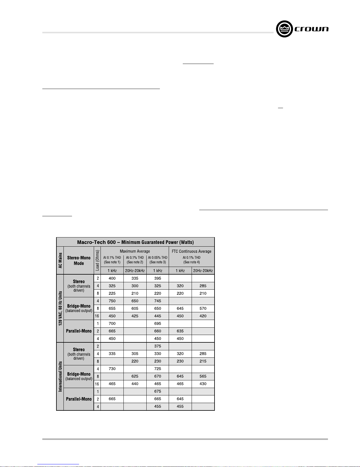
Macro-Tech 600/1200/2400 Power Amplifiers
Crown specifications are guaranteed for three years.
In an effort to provide you with as much information as possible about the high power-producing capabilities of your amplifier,
we have created the following power matrices.
Minimum Guaranteed Power Specifications
Crown’s minimum power specifications represent the absolute smallest amount of output power you can expect from your
amplifier when it is driven to full output under the given conditions. Some spaces in each matrix may be left blank because the
same guarantee is not provided for those conditions—however, your amplifier will perform well under all conditions listed in
each matrix.
When measuring power, 0.1% THD appears to be the industry standard for distortion. Two of the maximum average power
specifications shown in each minimum power matrix are measured at 0.1% THD so you can easily compare Crown specifications to those of other manufacturers. But this high level of distortion actually allows for some clipping which is undesirable.
Because of this, a maximum average power spec at 0.05% THD is included in each minimum power matrix which represents
non-clipped conditions. Although most manufacturers do not give you power specifications at 0.05% THD, we encourage
them to provide these specifications so you will have a more realistic representation of the way amplifiers should be used in the
real world—without a clipped output signal.
Many manufacturers publish power specs with a tolerance of ±1 dB or worse. This means their amplifier can deviate more than
20% in output! A 100-watt amplifier would meet their specification if it only produced 79.4 watts. Other manufacturers qualify
their specs by saying they are “typical,” “subject to manufacturing tolerances,” “single channel driven” or that they are specified
with “fuses bypassed.” Each of these statements effectively removes any performance guarantee. In fact, some manufacturers
use these tactics to generate large power numbers, and they don’t even print a disclaimer. We take a different approach at
Crown—our amplifiers are
specs are set below our “in-house” measurements, you can expect
power specs. We believe you should get what you pay for.
guaranteed
to meet or exceed their specifications for three years. Further, because our published
every
Crown amplifier to
exceed
its published minimum
Minimum Power Notes:
All minimum power specifications are based on
0.1% regulated AC mains and an ambient room
temperature of 70° F (21° C). International units
with multi-tap transformers are specified for the
worst-case transformer tap (normally 100 VAC,
50 Hz). The standard EIA power measurement
(RS-490) is not identified here because it is identical to the FTC Continuous Average Power specification.
1. A 1-kHz sine wave is presented to the amplifier and the output monitored for nonlinear distortion. The level is increased until the THD
reaches 0.1%. At this level the average power
per channel is reported.
2. A sine wave is presented to the amplifier over
the range from 20 Hz to 20 kHz and the output monitored for nonlinear distortion. The
level at each frequency is increased until the
THD reaches 0.1%. At this level the average
power per channel is reported.
3. A 1-kHz sine wave is presented to the amplifier and the output monitored for nonlinear distortion. The level is increased until the THD
reaches 0.05%. At this level the average
power per channel is reported.
4. Continuous power in the context of Federal
Trade Commission testing is understood to be
a minimum of five minutes of operation. Harmonic distortion is measured as the RMS sum
total and given as a percentage of the fundamental output voltage. This applies for all wattages greater than 0.25 watts.
Fig. 6.1 Macro-Tech 600 Minimum Power Matrix
Reference Manual
Page 29
Page 30
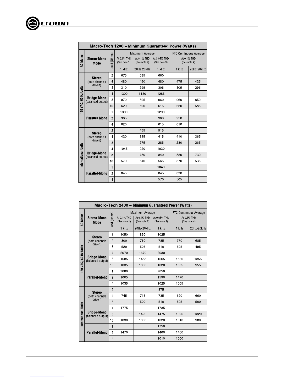
Macro-Tech 600/1200/2400 Power Amplifiers
Fig. 6.2 Macro-Tech 1200 Minimum Power Matrix
Fig. 6.3 Macro-Tech 2400 Minimum Power Matrix
Page 30 Reference Manual
Page 31
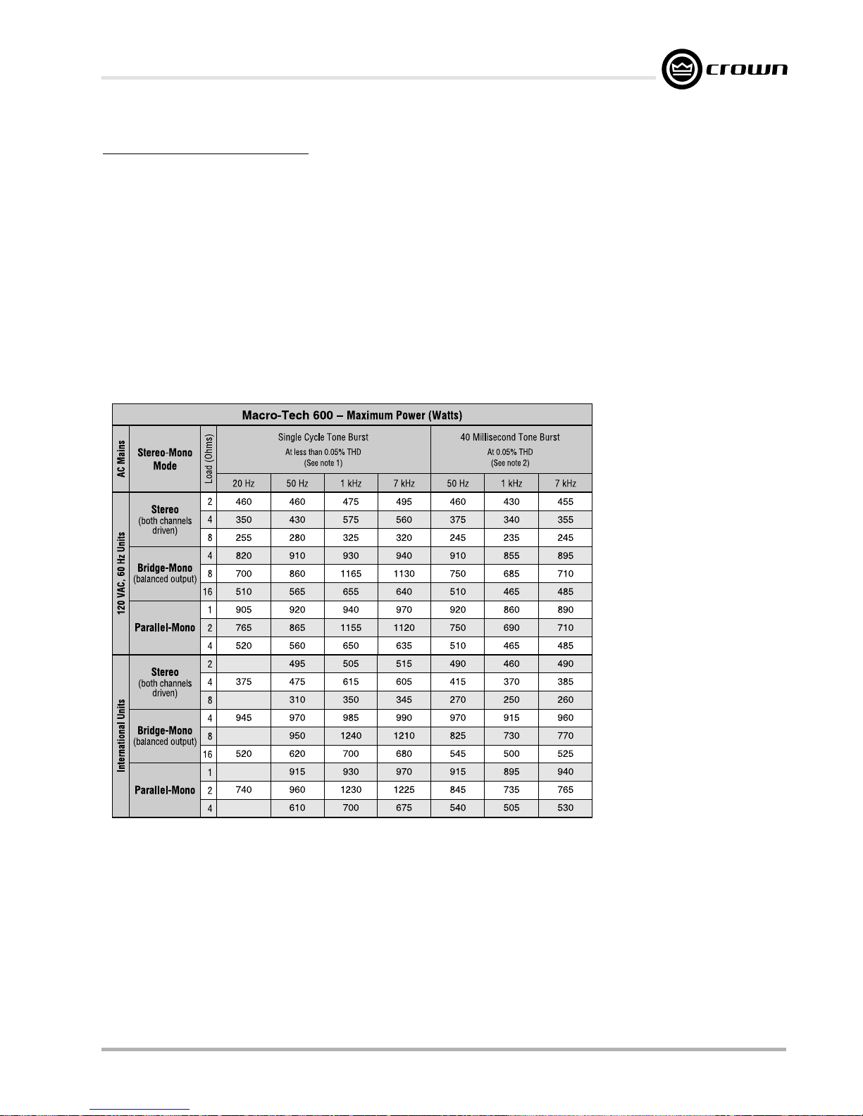
Macro-Tech 600/1200/2400 Power Amplifiers
Maximum Power Specifications
Crown’s maximum power specifications represent the largest amount of output power you can expect from your amplifier when
it is driven to full output under the given conditions. These specifications can be used to prevent loudspeaker and hearing
damage.
The maximum power matrices include specifications for single cycle and 40 millisecond burst sine waves. Burst signals act
like large transient peaks that are present in common source signals. Loudspeakers can respond to a single cycle burst, so the
single cycle burst specifications should be used to help you protect your loudspeakers. In contrast, a 40 millisecond burst
represents the typical response time of the human ear. Your ear will not respond to the entire dynamic change of a burst that
lasts less than 40 milliseconds.
The burst power specifications are provided at 0.05% THD which is a practical low-distortion condition. Operating the amplifier
at levels higher than 0.05% THD can result in output power levels that are higher than those listed in the maximum power
matrices.
Maximum Power Notes:
All maximum power specifications are
based on 0.1% regulated AC mains
and an ambient room temperature of
70° F (21° C). International units with
multi-tap transformers are specified for
the best-case transformer tap (normally 240 VAC, 60 Hz). Although it is
an unusual condition, your amplifier
can function well with AC mains voltages up to 10% over the specified line
voltage. With overvoltage conditions,
your amplifier may be capable of delivering instantaneous power levels up
to 20% greater than the specifications
in the matrix.
1. A single cycle sine wave is presented to the amplifier and monitored for nonlinear distortion. The
average power during the burst is
reported. Loudspeakers must be
able to withstand this level if they
are to be safely used with this amplifier.
2. A 40-millisecond sine wave burst
(10 percent duty cycle) is presented to the amplifier and monitored for nonlinear distortion. The
average power during the burst is
reported. This power level is a
measurement of the amplifier’s
maximum transient power that can
be perceived by the human ear.
Fig. 6.4 Macro-Tech 600 Maximum Power Matrix
Reference Manual
Page 31
Page 32
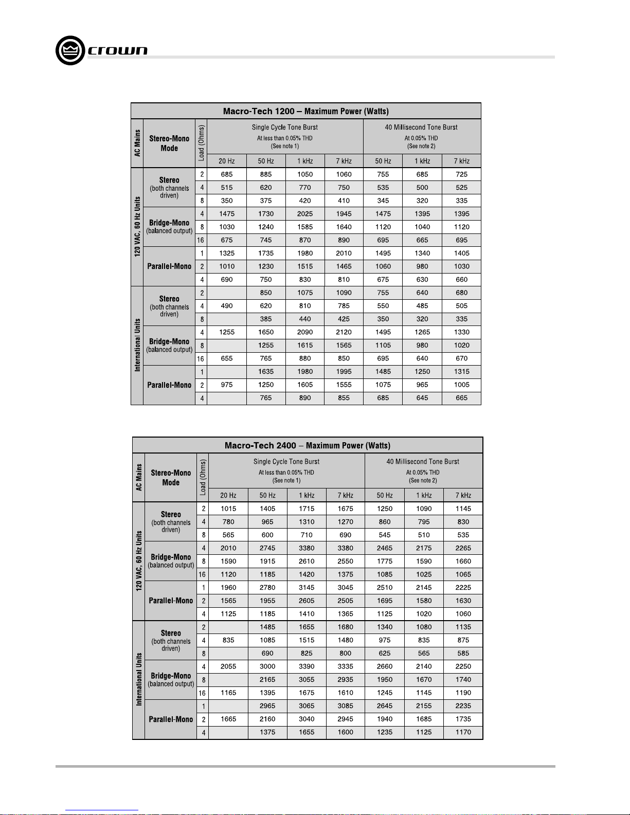
Macro-Tech 600/1200/2400 Power Amplifiers
Fig. 6.5 Macro-Tech 1200 Maximum Power Matrix
Fig. 6.6 Macro-Tech 2400 Maximum Power Matrix
Page 32 Reference Manual
Page 33
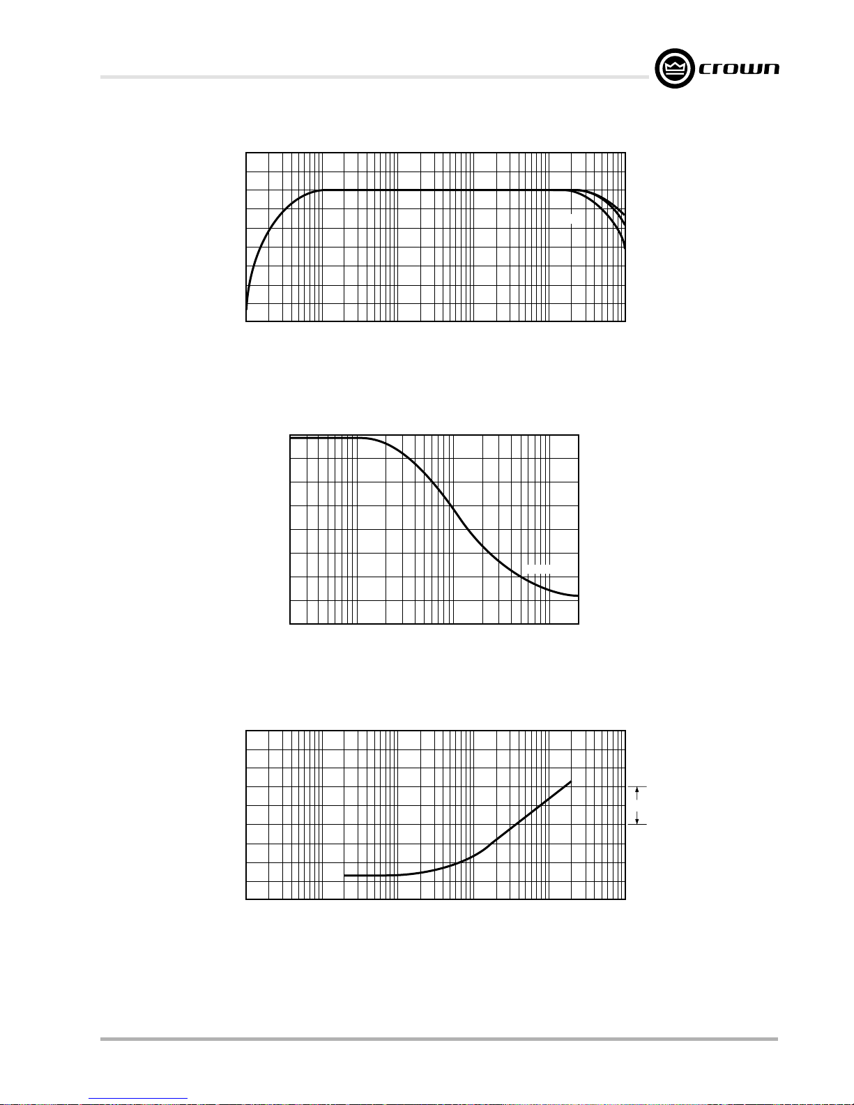
Macro-Tech 600/1200/2400 Power Amplifiers
(Hz)
+2
+1
0
–1
–2
dB
–3
–4
–5
–6
–7
10 100 1 K 10 K 100 K
Fig. 6.7 Typical Frequency Response
1400
1200
FREQUENCY (Hz)
1 watt
8 ohm
4 ohm
2 ohm
504.0
126.8
MILLIOHMS
31.8
1000
800
600
400
200
100
0
20
100 1 K 10 K
FREQUENCY (Hz)
8 ohm
20 K
Fig. 6.8 Typical Damping Factor
6 dB
8.0
2.0
Reference Manual
10 100 1 K 10 K 100 K
FREQUENCY
Fig. 6.9 Typical Output Impedance
Page 33
Page 34
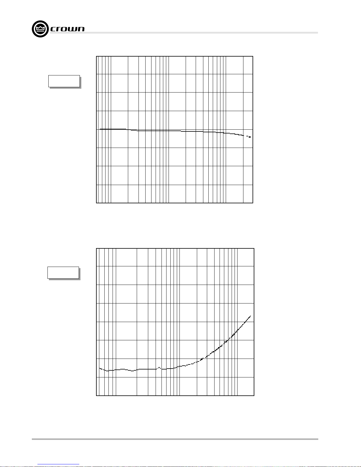
TEF
Measurement
Macro-Tech 600/1200/2400 Power Amplifiers
+45˚
0˚
–45˚
TEF
Measurement
®
100 1 K 10 K 20 K
TEF
FREQUENCY (Hz)
Fig. 6.10 Typical Phase Response
–51
–57
–63
dB
–69
–75
–81
100 1 K 10 K 20 K
Fig. 6.11 Typical Crosstalk for the Macro-Tech 600
Page 34 Reference Manual
®
TEF
FREQUENCY (Hz)
Page 35
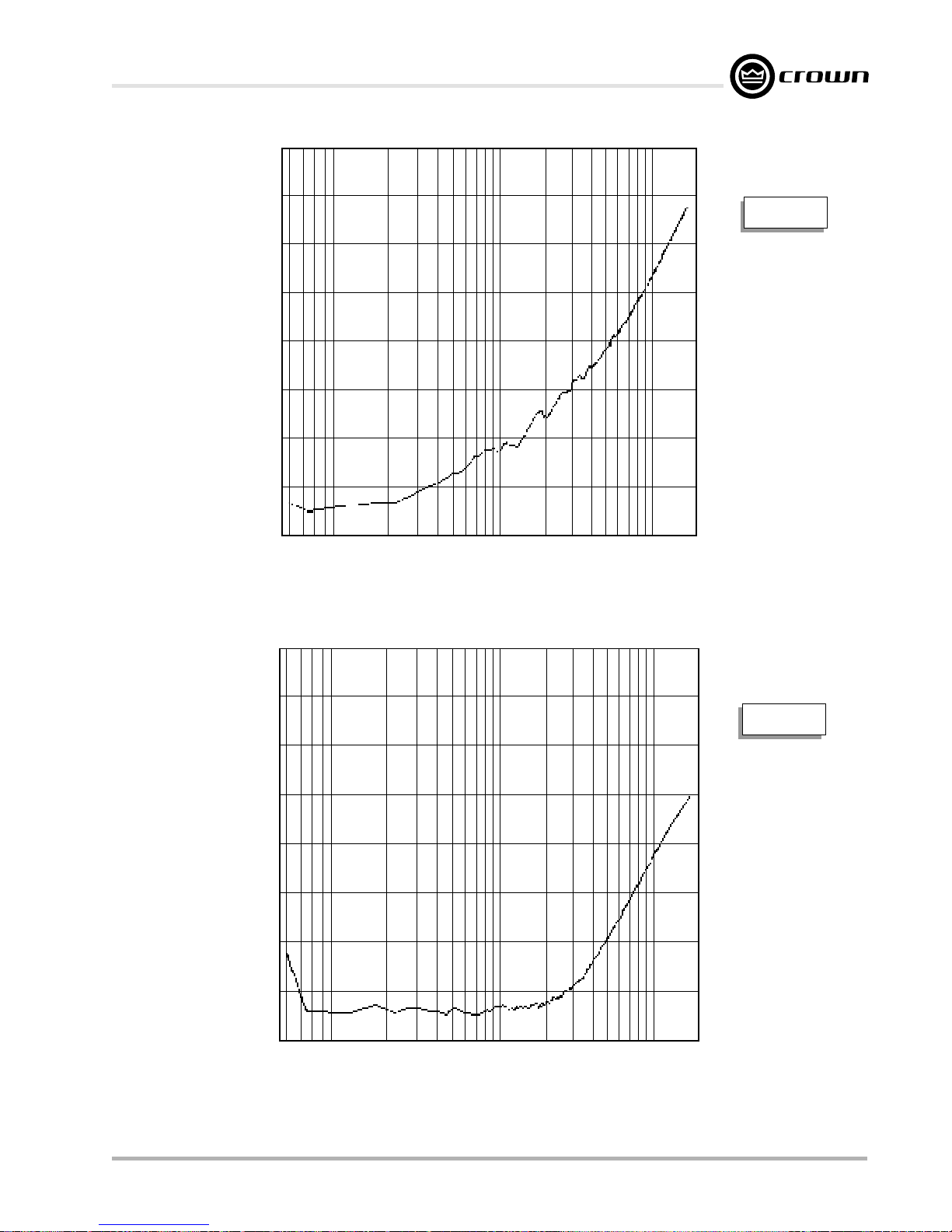
Macro-Tech 600/1200/2400 Power Amplifiers
–66
–72
–78
–84
dB
–90
–96
–102
®
100 1 K 10 K 20 K
TEF
FREQUENCY (Hz)
TEF
Measurement
Fig. 6.12 Typical Crosstalk for the Macro-Tech 1200
–60
–66
–72
–78
dB
–84
–90
–96
®
100 1 K 10 K 20 K
TEF
FREQUENCY (Hz)
TEF
Measurement
Fig. 6.13 Typical Crosstalk for the Macro-Tech 2400
Reference Manual
Page 35
Page 36
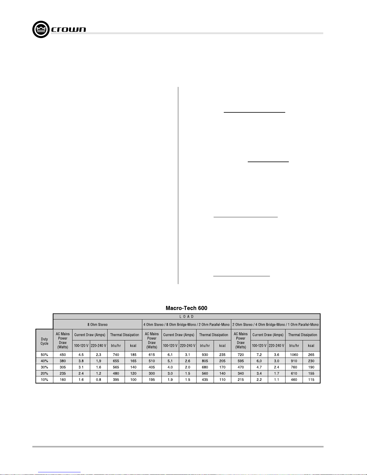
7 AC Power Draw and
g
)
()
y
()
Thermal Dissipation
This section provides detailed information about the
amount of power and current drawn from the AC mains
by the Macro-Tech
the amount of heat produced under various conditions.
The calculations presented here are intended to provide a realistic and reliable depiction of the amplifiers.
The following assumptions or approximations were
made:
• The amplifier’s available channels are loaded and full
power is being delivered.
• The amplifier efficiency at standard 1-kHz power is
estimated to be 65%.
• Quiescent power draw is 90 watts (an almost negligible amount for full-power calculations).
• Quiescent thermal dissipation equals 105 btu/hr at
90 watts.
• The estimated duty cycles take into account the typical crest factor for each type of source material.
• Duty cycle of pink noise is 50%.
• Duty cycle of highly compressed rock ‘n’ roll midrange is 40%.
• Duty cycle of rock ‘n’ roll is 30%.
• Duty cycle of background music is 20%.
• Duty cycle of continuous speech is 10%.
• Duty cycle of infrequent, short duration paging is 1%.
600, 1200
and
2400
amplifiers and
Macro-Tech 600/1200/2400 Power Amplifiers
Here are the equations used to calculate the data presented in Figures 7.1 through 7.3:
AC Mains Power
Draw (watts)
Total output power with all
channels driven (watts)
=
Amplifier Efficiency (.65)
Duty
x
Cycle
Quiescent Power
+
Draw (watts)
The quiescent power draw of 90 watts is a maximum
value and includes power drawn by the fan. The following equation converts power draw in watts to current
draw in amperes:
AC Mains Power
Current Draw
(amperes)
=
AC Mains
Volta
Draw (watts)
x
e
Factor (.83
Power
The power factor of 0.83 is needed to compensate for
the difference in phase between the AC mains voltage
and current. The following equation is used to calculate
thermal dissipation:
Thermal
Dissipation
(btu/hr)
Total output power with all
channels driven (watts)
=
Amplifier Efficiency (.65)
x
Duty
Cycle
.35
x
Quiescent Power
+
Draw (watts)
x
3.415
The constant 0.35 is inefficiency (1.00–0.65) and the
factor 3.415 converts watts to btu/hr. Thermal dissipation in btu is divided by the constant 3.968 to get kcal. If
you plan to measure output power under real-world
conditions, the following equation may also be helpful:
Thermal
Dissipation
(btu/hr)
Total measured output power
from all channels (watts)
=
Amplifier Efficienc
(.65)
.35
x
+
Quiescent Power
Draw (watts)
x
3.415
Fig. 7.1 Macro-Tech 600 Power Draw, Current Draw and
Page 36 Reference Manual
Thermal Dissipation at Various Duty Cycles
Page 37
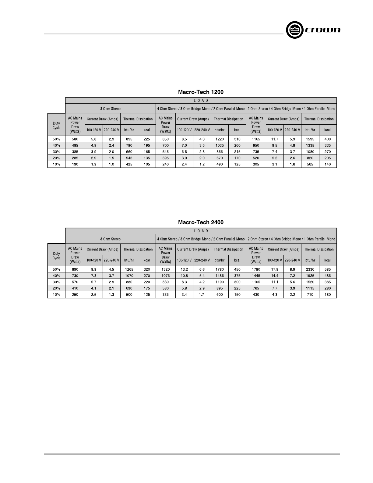
Macro-Tech 600/1200/2400 Power Amplifiers
Fig. 7.2 Macro-Tech 1200 Power Draw, Current Draw and
Thermal Dissipation at Various Duty Cycles
Fig. 7.3 Macro-Tech 2400 Power Draw, Current Draw and
Reference Manual
Thermal Dissipation at Various Duty Cycles
Page 37
Page 38
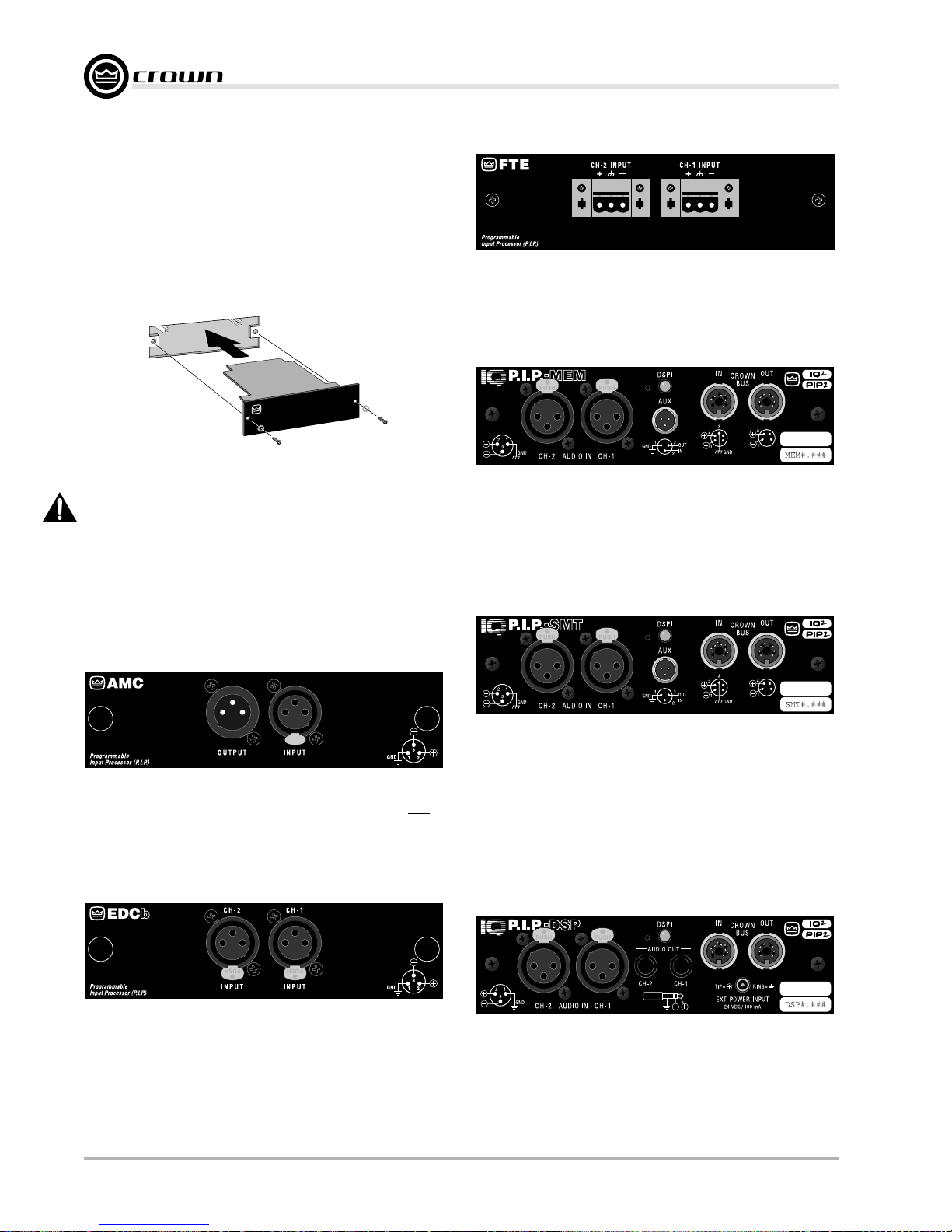
8 Accessories
8.1 PIP Modules
One advantage of Macro-Tech amplifiers is the ability
to customize them using PIP (Programmable Input Processor) and PIP2 modules. Macro-Tech amplifiers are
equipped with an edge card connector inside the back
panel PIP compartment. The modules install easily:
L
E
N
A
P
K
C
A
B
O
R
E
I
F
I
L
P
M
A
F
.
P
.
I
.
P
E
L
U
D
O
M
Macro-Tech 600/1200/2400 Power Amplifiers
P.I.P.®–FTE uses balanced 1:1 transformers to isolate the amplifier from the input signal. It also includes 12-dB/octave RFI filters,
18-dB/octave high-pass filters, and 6-dB/octave 3-kHz shelving
networks for “constant-directivity” horn equalization. Screw terminal plugs are provided for input.
Fig. 8.1 Installing a
PIP
Module
WARNING: Disconnect power to the amplifier when
installing or removing a PIP module.
PIPs carrying the PIP2 logo are configured to use one
or more of the PIP2 enhanced features. These features
are only available in a PIP2-compatible amplifier. Of
course, the exact features used will depend upon the
function of the PIP2 module. Here are some of the available PIP and PIP2 modules:
P.I.P.®–AMCb unites many features of the P.I.P.-XOV and P.I.P.–
CLP. It offers a variable 4th-order Linkwitz-Riley crossover and an
IOC-driven, variable threshold compressor. In addition, it provides “constant-directivity” horn equalization and filter-assisted
B6 vented box equalization. Biamping and triamping capabilities
are provided via three-pin XLR connectors.
IQ–P.I.P.®–MEM is PIP2-compatible and integrates the amplifier
into Crown’s patented IQ System. The IQ System provides computer control of 1 to 2000 amplifiers. For example, each amplifier
channel can be monitored and controlled from a personal computer attached to an IQ System. A memory backup feature enables the IQ–PIP–MEM to remember all configuration settings
when the power is turned off.
IQ–P.I.P.®–SMT is also PIP2-compatible and includes all the features of the IQ–P.I.P.®–MEM plus SmartAmp™ capability. Once
the unit has been configured by an IQ System, its SmartAmp
capabilities enable it to function autonomously. We call this distributed intelligence. The SmartAmp™ features include a smooth
output limiter for transparent loudspeaker protection, power supply gates for energy savings, ODEP conservation to protect output devices with precision input signal control, interrupt-driven
reporting that lets you define error conditions, and configurable
short circuit detection.
P.I.P.®–EDCb combines a sophisticated error-driven compressor and smooth limiter with a maximum level setting and a subsonic filter for each channel. The compressors have adjustable
attack and release times, and can be set to track each other. The
compressors activate when a signal would otherwise clip the
input, an IOC error occurs, or the output exceeds the selected
threshold. The subsonic filters have corner frequencies of 24,
28, 32 and 36 Hz.
Page 38 Reference Manual
IQ–P.I.P.®–DSP is PIP2-compatible and provides digital signal
processing capabilities to your amplifier, replacing the need for
outboard signal processing equipment such as equalizers,
crossover networks, signal delays and compressors. In addition,
the IQ–P.I.P.–DSP includes all the SmartAmp features of the IQ–
P.I.P.–SMT to give you access to standard IQ System amplifier
functions and autonomous operation.
Page 39
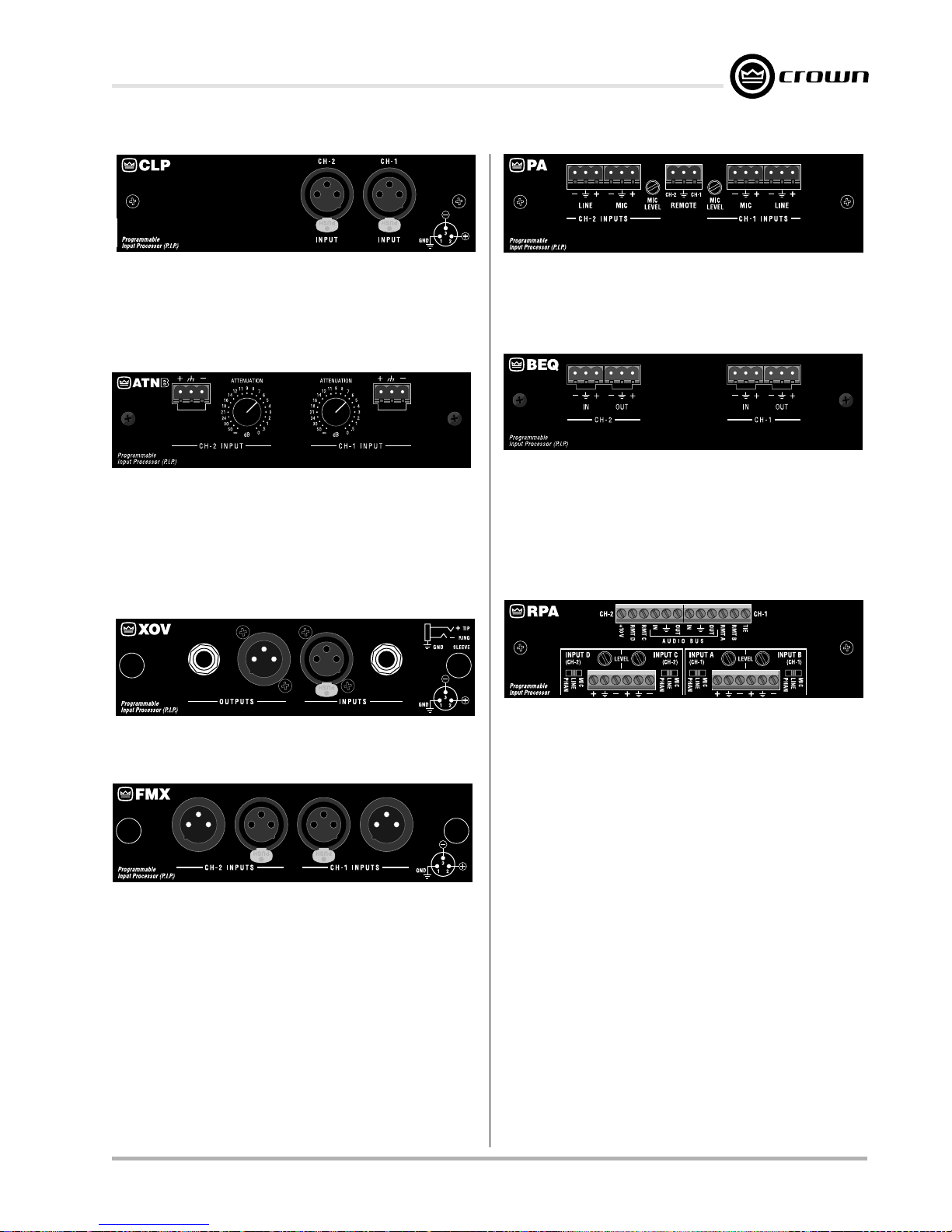
Macro-Tech 600/1200/2400 Power Amplifiers
perationtion.
P.I.P.®–CLP detects and prevents overload. Its compressor
is driven by the amplifier’s built-in IOC error detection circuitry.
Unlike typical signal-driven compressors, it only compresses
the signal to prevent overload. It can deliver up to 13 dB of
additional headroom without being noticeable.
P.I.P.®–ATNB uses balanced 1:1 transformers to isolate the
amplifier from the input signal. It also includes 12-dB/octave
RFI filters, variable 18-dB/octave high-pass filters, and 6-dB/
octave 3-kHz shelving networks for “constant-directivity” horn
equalization. The module also includes a calibrated 21-step
precision attenuator for each channel. Screw terminal plugs
are provided for input.
P.I.P.®–XOV is a versatile 18-dB/octave mono crossover/filter
with biamping and triamping capabilities
P.I.P.®–PA adds a switchable, balanced, low-impedance mic
input, a balanced line-level input and a compressor to each
channel. Remote switching circuitry provides quick and quiet
fades from mic to line and back.
P.I.P.®–BEQ is a two-channel module providing equalization
for BOSE® loudspeakers. For example, the P.I.P.–BEQ can be
used in place of a BOSE 102 controller. Screw terminal plugs
provide balanced connections. Each input channel has an
output from the PIP that can be independently configured for
output with no processing, loudspeaker equalization or loudspeaker equalization with bass-cut.
P.I.P.®–RPA adds the features of a 4x2 mixer to your amplifier.
Its four inputs accept mic- or line-level input. It offers priority
switching (“voice-over”) of each input and remote level control with the RPA–RMT. Other features include bus inputs and
outputs, adjustable input sensitivity, phantom power and RFI
suppression. Input isolation transformers are optional.
P.I.P.®–FMX facilitates “daisy-chaining” balanced amplifier inputs. Female to male three-pin XLR connectors are used to
passively bridge the inputs.
Reference Manual
For more information on these or other PIPs under development, contact your local dealer or Crown’s Technical Support Group.
Page 39
Page 40
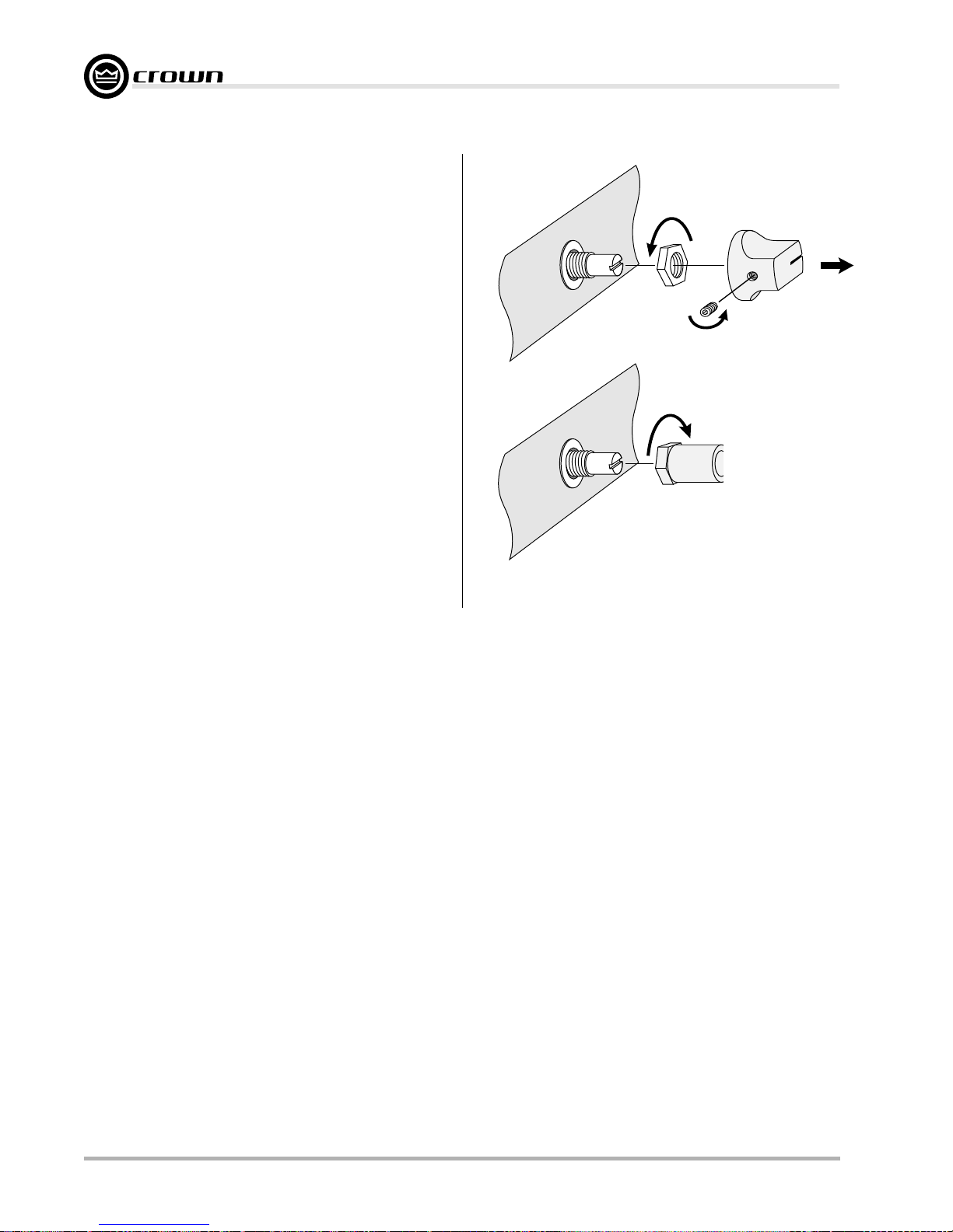
8.2 Cooling Fan Options
Every Macro-Tech amplifier has a built-in high-velocity
fan that provides optimum cooling. Two optional replacement fan blades are available for special cooling
requirements. Crown part C 6594-3 is a quieter, lowvelocity fan blade that in many cases can provide adequate cooling. Crown part C 6593-5 is a reverse
air-flow fan blade which changes the direction of the air
flow in and out of the amplifier (not recommended for
the Macro-Tech 2400). Important: The optional replacement fan blades should only be installed by a qualified
technician.
8.3 Level Control Shaft Lock
A security accessory, the shaft lock can be used to secure your amplifier’s level controls in situations where
the front panel controls are subject to tampering. One
is needed for each channel. They can be ordered
through the Crown Service/Parts Department. For more
information, contact the Crown Service Department.
Macro-Tech 600/1200/2400 Power Amplifiers
Fig. 8.2 Installing a Level Control Shaft Lock
Page 40 Reference Manual
Page 41
Macro-Tech 600/1200/2400 Power Amplifiers
9 Service
This unit has very sophisticated circuitry which should
only be serviced by a fully trained technician. This is
one reason why each unit bears the following label:
Your repaired unit will be returned via UPS ground.
Please contact us if other arrangements are
required.Factory Service Shipping Instructions:
CAUTION: To prevent electric shock, do not remove
covers. No user serviceable parts inside. Refer servicing to a qualified technician.
9.1 Worldwide Service
Service may be obtained from an authorized service
center. (Contact your local Crown/Amcron representative or our office for a list of authorized service centers.)
To obtain service, simply present the bill of sale as proof
of purchase along with the defective unit to an authorized service center. They will handle the necessary
paperwork and repair.
Remember to transport your unit in the original factory
pack.
9.2 North American Service
Service may be obtained in one of two ways: from an
authorized service center or from the factory. You may
choose either. It is important that you have your copy of
the bill of sale as your proof of purchase.
9.2.1 Service at a North American Service Center
This method usually saves the most time and effort.
Simply present your bill of sale along with the defective
unit to an authorized service center to obtain service.
They will handle the necessary paperwork and repair.
Remember to transport the unit in the original factory
pack. A list of authorized service centers in your area
can be obtained from our Technical Support Group.
9.2.2 Factory Service
To obtain factory service, fill out the service information page found in the back of this manual and send it
along with your proof of purchase and the defective
unit to the Crown factory.
For warranty service, we will pay for ground shipping
both ways in the United States. Contact Crown Factory
Service or Technical Support to obtain prepaid shipping labels prior to sending the unit. Or, if you prefer,
you may prepay the cost of shipping, and Crown will
reimburse you. Send copies of the shipping receipts to
Crown to receive reimbursement.
Always use the
original factory pack
to transport the unit.
1. When sending a Crown product to the factory for
service, be sure to fill out the service information
form that follows and enclose it inside your unit’s
shipping pack. Do not send the service information form separately.
2. To ensure the safe transportation of your unit to
the factory, ship it in an original factory packing
container. If you don’t have one, call or write
Crown’s Parts Department. With the exception of
polyurethane or wooden crates, any other packing material will not be sufficient to withstand the
stress of shipping. Do not use loose, small size
packing materials.
3. Do not ship the unit in any kind of cabinet (wood
or metal). Ignoring this warning may result in extensive damage to the unit and the cabinet. Accessories are not needed—do not send the
instruction manual, cables and other hardware.
If you have any questions, please call or write the Crown
Technical Support Group.
Crown International
Technical Support / Factory Service
1718 W. Mishawaka Rd., Elkhart, Indiana 46517
U.S.A.
T
elephone: 574-294-8200
800-342-6939 (North America,
Puerto Rico, and Virgin Islands only)
Facsimile: 574-294-8301 (Technical Support)
574-294-8124 (Factory Service)
Fax Back: 574-293-9200 (North America only)
800-294-4094 (North America only)
574-294-8100 (International)
Internet: http://www.crownaudio.com
Reference Manual
Page 41
Page 42

Crown Factory Service Information
Shipping Address: Crown Factory Service, 1718 W. Mishawaka Rd., Elkhart, IN 46517
Phone: 1-800-342-6939 or 1-574-294-8200 Fax: 1-574-294-8124
Owner’s Name: _________________________________________________________________________
Shipping Address: ______________________________________________________________________
Phone Number: ______________________________ Fax Number: _____________________________
Model: _________________________ Serial Number: ______________ Purchase Date: ____________
NATURE OF PROBLEM
(Be sure to describe the conditions that existed when the problem occurred and what attempts were made to correct it.)
______________________________________________________________________________
______________________________________________________________________________
______________________________________________________________________________
______________________________________________________________________________
______________________________________________________________________________
______________________________________________________________________________
______________________________________________________________________________
______________________________________________________________________________
______________________________________________________________________________
______________________________________________________________________________
______________________________________________________________________________
______________________________________________________________________________
Detach and send with unit.
______________________________________________________________________________
______________________________________________________________________________
______________________________________________________________________________
Other equipment in your system:__________________________________________________________
______________________________________________________________________________
______________________________________________________________________________
______________________________________________________________________________
______________________________________________________________________________
______________________________________________________________________________
______________________________________________________________________________
If warranty has expired, payment will be: Cash/Check VISA MasterCard C.O.D.
Card Number:___________________________ Exp. Date:_______ Signature:____________________________
ENCLOSE THIS PORTION WITH THE UNIT. DO NOT MAIL SEPARATELY.
 Loading...