

Crown
D-150

DUAL CHANNEL POWER AMPLIFIER

free standing

mount

UNIVERSAL
UNIVERSAL MOUNTING
17" wide, 5¼" high, 9" deep Ideal for rack mounting with optional FP Classic styling in the optional enclosure As a basic amplifier, tucked away, out of sight
UNIVERSAL POWER RANGE
im Hersteller Cleanest power for most hi-fi systems Michael Otto Cop-amp front end for linear bandwidth and gain Really quiet performance — drives electrostatic head phones without pads
UNIVERSAL LOAD MATCHING
Matches any load from 4 ohms to infinity Offers higher damping factor via Crown-pioneered AB+B direct-coupled output New volt-ampere limiting protection is automatic eliminates power supply fusing
UNIVERSAL PRICE
Priced within the range of the audio buff who takes his music seriously
$399 — FP front panel $30 — optional 5D cabinet $33
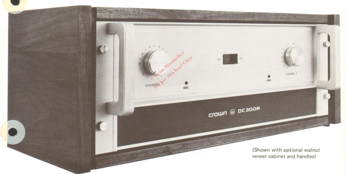
Performance equal to the famous DC-300
100% American made with industrial and computer arade components
round trip shipping
Each unit accompanied by its own hand-entered proof-of-performance.
COMPLETE SPECIFICATIONS:
| Power Output: |
Power output not less than 75 watts
R.M.S. per channel into 8 ohms (both channels operating) 20-20,000Hz at rated distortion. Typically 100 watts |
Input: |
Impedance - Nominal 25K ohm, screw-
driver adjust on rear. Input sensi- tivity 1.2V for full output. Standar ¼" phone-jack on rear. |
||||
| R.M.S. per channel into 8 ohms, 140 watts R.M.S. per channel into 4 ohms. | Turn-on: | Instantaneous, with no program delay, and minimum thump. | |||||
| Power Bandwidth: | Power bandwidth ±1dB, 5-20,000Hz at 75 watts R.M.S. per channel into 8 ohms. | Circuit: |
Unique wideband, stable design utilizing
a new linear IC (dual op-amp). Total equivalent of 40 transistors, 24 diodes, and four rectifier-diodes. |
||||
| IM Distortion: | IM - less than 0.05%, 0.01 watt to 75 watts, 60Hz and 7.000Hz mixed 4:1. | ||||||
| Harmonic - less than 0.05%, 0.01 watt to 75 watts, 20-20,000Hz. | Protection: | Amplifier is short- and mismatch- and open-circuit-proof. Unique V-I limiting | |||||
| Frequency Response: | +0.1dB 20-20,000Hz at 1 watt into 8 |
is instantaneous with no thumps, cut-
out, etc. |
|||||
| Phase Response: |
+
15°, 20-20,000Hz at 1 watt into
8 ohms. |
Power Supply: |
Two massive capacitors with energy-
storage exceeding 20 joules. Total of two regulated supplies for complete |
||||
| Hum and Noise: | 110dB below 75 watts R.M.S. output. | AC power-line. | |||||
| Damping Factor: | Greater than 200 from zero to 1000Hz into 8 ohms. | Dimensions: | 17" width, 5¼" high, 9" deep (from mounting surface). All-aluminum con- | ||||
| Verification: | Each unit accompanied by its individual hand-entered proof-of-performance report. | struction with massive chassis. Amplifier will panel-mount in a 16 3 / 4 " x 5" opening (with optional front panel). With adapters, standard 19" rack mount. | |||||
| Load Impedance: | 4 to 16 ohms (complete stability with any load); dual binding-post outputs. | Accessories: | FP Kit - for panel, cabinet and rack mounting - price $30. 5D Cabinet - | ||||
| Construction: | 100% American-made with industrial grade construction for years of con- |
custom oiled, walnut enclosure (re-
quires FP kit) - price $33. |
|||||
| tinuous use. | Weight: | 22 pounds (24 pounds rack mount). | |||||
TYPICAL CHARACTERISTICS ..

3 Year Warranty: All parts and labor, including round-trip shipping
Crown
INTERNATIONAL BOX 1000 ELKHART, INDIANA PHONE: (219) 523-491
MADE ONLY IN AMERICA
Skilled American craftsmen fabricate, assemble, and individually adjust each CROWN amplifier to provide you unequalled quality.
ICC IHE DIFFERENT DISTORTION INDICATOR
WHAT: IOC (Input-Output Comparator) acts in conjunction with existing amplifier circuitry to monitor musical waveforms. The system analyzes the amplifier's input and output waveforms noting the difference.
WHY:
: CROWN's IOC system brings you these benefits:
- 1.) Accuracy: Whenever rated distortion levels in the amplifier are approached, the user is notified under actual listening conditions. When IOC is off, the listener is assured that he is avoiding excessive distortion levels, and that the input signal is virtually identical to its output.
- 2.) Sensitivity: Short durations of distortion levels triggering IOC are held to allow you time to monitor them.
- 3.) Compatibility: IOC allows you, without elaborate test equipment, to determine the proper size amplifier for your listening needs whatever they may be.
WHO: CROWN DC-300A and D-150A amplifiers now incorporate a unique music distortion indication system called IOC.
- 4.) Retrofitability: Because of the extremely useful information that IOC provides and in keeping with CROWN's policy of avoiding continual model changes and planned obsolescence existing owners of DC-300A's and D-150A's may have their units updated for $70.00. Units must be returned to the factory as the cost includes laboratory check-out after IOC is installed.
- HOW: Inherent in the design of CROWN amplifiers is the presence of a correction signal anytime the feed-back loop indicates a difference between the input and output of the amplifier. The input IC acts as an input and output comparator on a continuing basis. When any kind of nonlinear behaviour appears, the IC generates a correction signal in order to match the output to the input again. The CROWN IOC network monitors this correction signal and lights the indicator LED when a correction signal indicating any kind of nonlinearity is present.
The advantage over the traditional clip indicator becomes apparent when the action of such a circuit is considered. Sensitive only to output voltage, the more common LED clip indicator can not respond to protection circuit activation (caused by either signal or load problems) or slew induced distortion (commonly called Transient Intermodulation Distortion or TIM), and may not even report amplifier clipping if it is brief.

The IOC , by contrast reports any and all forms of amplifier non-linear behaviour, including SID, protection circuit activation, and all amplifier clipping no matter how brief. The circuit sensitivity is extremely high, as the front panel display is activated before amplifier distortion specifications (.05% THD, IMD) are reached.
WHERE: IOC is available only from your CROWN dealer. See him today!

1718 W. MISHAWAKA ROAD, ELKHART, INDIANA 46514, (219) 294-5571, TWX 810-294-2160


The CROWN D-150A is a single or dual channel power amplifier designed for precision amplification of frequencies from 1Hz to 20KHz. The design of the D-150A provides extremely low harmonic and intermodulation distortion with very low noise. A switch on the rear of the unit allows stered or mono operation with no internal wiring changes. In the mono mode, the D-150A is capable of a 50 volt balanced line output. The unit operates on AC current from 120V to 240V. See complete specifications on reverse side.
The D-150A embodies the simplest and yet most accurate distortion display available in any audio product. The IOC-Input-Output Comparator-senses any form of amplifier non-linear behaviour and reports its existence through front panel LED's. Slew-induced distortion, protection circuit activation, and clipping distortion will all be detected by the IOC circuit at levels below the rated distortion of the amplifier. Thus, the amplifier becomes a valuable tool in the hands of the user to facilitate proper amplifier-speaker-environment matching, as well as a continuous monitor of the purity of the signal reproduction through the amplifier under actual operating conditions.
The D-150A has two direct coupled amplifier circuits employing a dual integrated op amp and silicon transistors in all amplifier stages. Input voltage amplifiers are powered by two regulated voltage supplies. The output stages utilize CROWN-patented circuitry, including the class AB + B configuration. No quiescent bias current is used in the output transistors for better efficiency and wide band response.
The D-150A contains output protection circuitry pioneered by CROWN. This circuitry protects the unit completely against shorted, mismatched, or open loads and eliminates completely the need for DC fuses and mode switches to protect the amplifier. With this unique protection system, the D-150A can safely drive any speaker load, resistive or reactive, with no fear of harming the amplifier. The speakers can be paralleled with no deterioration of sound quality since changing the load impedance only affects the maximum power available, not the ability of the amplifier to produce clean sound.
All components of the D-150A must meet the highest criteria for long term performance. All resistors in critical areas are 1% tolerance. Integrated circuits and transistors are individually tested before assembly. After assembly, each amplifier is thoroughly tested and must exceed our guaranteed specifications before it is shipped. A prooof of performance sheet accompanies each unit showing actual specifications attained.
The CROWN D-150A amplifier carries a full warranty for three years against failure. Parts, labor, and round trip shipping are provided at no charge should any defects occur.
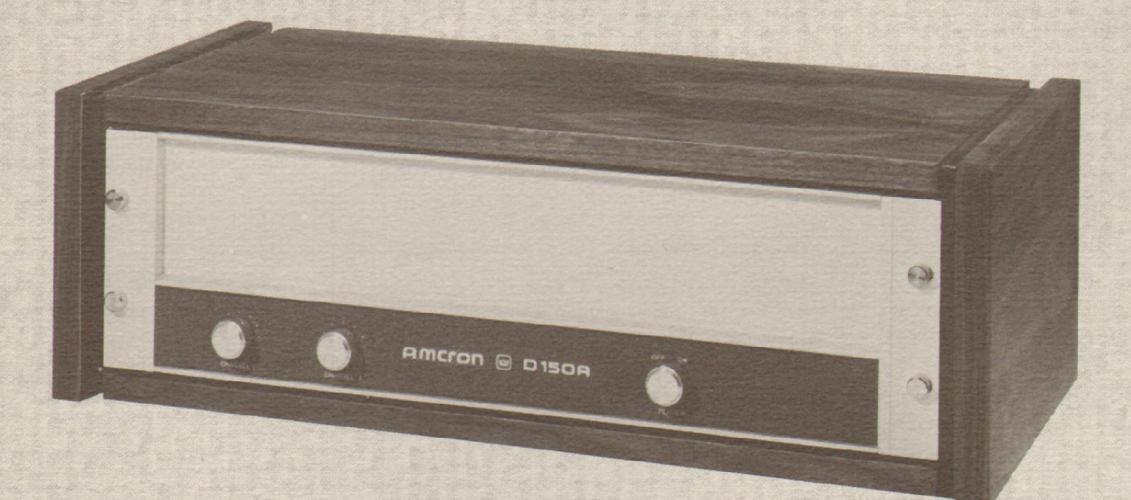
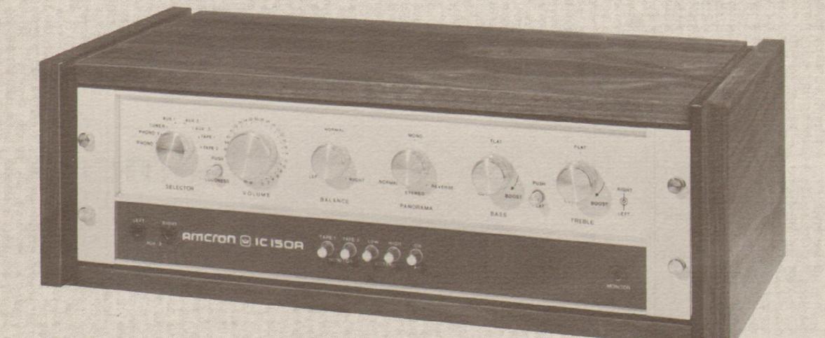
*The D-150A may be rack mounted, or as shown, an optional cabinet is available.
D-150A SPECIFICATIONS
STEREO
Output Power
80 watts per channel minimum BMS (both channels operating) into an 8 ohm load over a bandwidth of 1Hz-20KHz at a rated RMS sum total harmonic distortion of 0.05% of the fundamental output voltage
125 watts per channel minimum RMS (both channels operating) into a 4 ohm load over a bandwidth of 1Hz-20KHz at a rated RMS sum total harmonic distortion of 0.1% of the fundamental output voltage.
Frequency Response
±0.1 dB DC-20KHz at 1 watt into 8 ohms; +1 dB DC-100KHz at 1 watt into 8 ohms.
1KHz Power
90 watts RMS into 8 ohms, per channel, both channels operating, 0,1% total har-
Harmonic Distortion
Less than 0.001% from 20Hz-400Hz and increasing linearly to 0.05% at 20KHz at 80 watts RMS per channel into 8 ohms
LM Distortion (60Hz-7KHz 4:1)
Less than 0.05% from 0.01 watt to 0.25 watts and less than 0.01% from 0.25 watts to 80 watts into 8 ohms, per channel
Noise Transfer Intermodulation Distortion (NTIM)
Less than .005% at 80 w/ch peak equivalent level into 8 ohms. Test signal 10KHz white noise (crest factor 3.9); distortion products measured below 10KHz; NTIM testing is highly sensitive to audible products of high frequency distortion mechanisms
Slewing Rate
6 volts per microsecond (slewing rate is the maximum value of the first derivative of the output signal or the maximum slope of the
Damping Factor
Greater than 400, DC-400Hz into 8 ohms.
Output Impedance
Less than 15 milliohms in series with less
Load Impedance
Bated for 8 ohm and 4 ohm usage: safely drives any load including completely reactive loads
Voltage Gain
20.6 ±2% or 26.3 dB ±.2 dB at maximum gain.
Input Sensitivity 1.19 volts ± 2% for 80 watts into 8 ohms.
Output Signal
Unbalanced, dual channel.

MONAURAL
Output Power
160 watts minimum RMS into a 16 ohm load over a bandwidth of 1Hz-20KHz at a rated RMS sum total harmonic distortion of 0.05% of the fundamental output voltage.
250 watts minimum RMS into a 8 ohm load over a bandwidth of 1Hz-20KHz at a rated RMS sum total harmonic distortion of 0.1% of the fundamental output voltage.
Frequency Response
±0.15 dB DC-20KHz at 1 watt into 16 ohms: +1 dB DC-60KHz at 1 watt into 16 ohms 1KHz Power
180 watts RMS into 16 ohms 0.1% total
Harmonic Distortion
Less than 0.001% from 20-400Hz and increasing linearly to 0.05% at 20KH2 at 160 watts into 16 ohms.
LM Distortion
Less than 0.05% from 0.01 watter 0.25 watts and less than 0.01% from 0.25 watts to 160 watts into 16 ohms per channel.
Noise Fransfer Intermodulation Distortion (NTIM)
Less than 007% at 160 watts peak equivalent level into 16 ohms. Test signal 10KHz white noise (crest factor 3.9); distortion products measured below 10KHz: NTIM testing is highly sensitive to audible products of high frequency distortion mechanisms
Slewing Rate
12 volts per microsecond (slewing rate is the maximum value of the first derivative of the
Damping Factor
Greater than 400, DC-400Hz into 16 ohms.
Output Impedance
Less than 30 milliohms in series with less
Load Impedance
Rated for 16 ohm and 8 ohm usage; safely drives any load including completely reactive
Voltage Gain
41.2 ± 2% or 32.3 dB ± 0.2 dB at maximum gain. Input Sensitivity
1.19 volts+2% for 160 watts into 16 ohms.
Output Signal Balanced, single channel.
1718 West Mishawaka Road Elkhart, Indiana 46514 219-294-5571
GENERAL
Hum and Noise (20Hz-20KHz) 110 dB below rated output.
Phase Response +0, -15° DC-20KHz at 1 watt.
Input Impedance 25K ohms, ±30%
Amplifier Output Protection
Short, mismatch, and open circuit proof. Limiting is instantaneous with no flyback pulses, thumps, cutout, etc. No premature
Overall Protection
AC line fused. Thermal switch in AC line protects against over-heating caused by insufficient ventilation. Controlled slewing rate voltage amplifiers protect overall amplifier against RF burnouts. Input overload protection is furnished by internal resistance at inputs of amp.
DC Output Offset
(Shorted Input) 10 millivolts or less, internally adjustable to zero.
Instantaneous with minimum thumps and no program delay.
Circuit
Wideband multiple feedback loop design utilizing one linear IC (dual op-amp). Total equivalent of 47 transistors 24 signal diodes 3 zener diodes, and 6 rectifier diodes.
Power Supply
Massive computer grade filter capacitors store over 20 joules of energy. Two requlated supplies for complete isolation and
Power Requirements
Requires 50-400Hz AC on 120 volts or 240 volts ±10% operation. Draws 30 watts or less on idle, 250 watts on 160 watts total output.
Heat Sinking
The entire amplifier is used as a heat sink. 3/16 inch thick chassis acts as a heat sink
All aluminum construction for maximum
Two input level controls on front panel with power switch and pilot light. Stereo-mono
Input - 1/4 inch phone jacks Output - Color coded binding posts AC line - 3-wire (grounded) male connector
Dimensions and Weight
17 inches long 5-1/4 inches high 8-3/4 inches deep (for mounting surface of front panel), 19 inches long with standard rack mounting brackets installed; 25 pounds.

D-150A
The AMCRON D-150A is a single or dual channel power amplifier designed for precision amplification of frequencies from 1Hz to 20 kHz. The design of the D-150A provides extremely low harmonic and intermodulation distortion with very low noise. A switch on the rear of the unit allows stereo or mono operation with no internal wiring changes. In the mono mode, the D-150A is capable of a 50 volt balanced line output. The unit operates on AC current from 120V to 240V. See complete specifications on reverse side.
The D-150 A has two direct coupled amplifier circuits employing a dual integrated op amp and silicon transistors in all amplifier stages. Input voltage amplifiers are powered by two regulated voltage supplies. The output stages utilize AMCRON patented circuitry, including the class AB + B configuration. No quiescent bias current is used in the output transistors for better efficiency and wide band response.
The D-150A contains output protection circuitry pioneered by AMCRON. This circuitry protects the unit completely against shorted, mismatched or open loads and eliminates completely the need for DC fuses and mode switches to protect the amplifier. With this unique protection system, the D-150A can safely drive any speaker load, resistive or reactive with no fear of harming the amplifier. The speakers can be paralleled with no deterioration of sound quality since changing the load impedance only affects the maximum power available not the ability of the amplifier to produce clean sound.
All components of the D-150A must meet the highest criteria for long term performance. All resistors in critical areas are 1% tolerance. Integrated circuits and transistors are individually tested before assembly. After assembly, each amplifier is thoroughly tested and must exceed our guaranteed specifications before it is shipped. A proof of performance sheet accompanies each unit showing actual specifications attained.
*The D-150A may be rack mounted, or as shown, an optional cabinet is available.
D-150A Specifications
STEREO
Output Power
80 Watts per channel minimum RMS (both channels operating) into an 8 ohm load over a bandwidth of 1Hz-20kHz at a rated RMS sum total harmonic distortion of 0.05% of the fundamental output voltage.
Frequency Response
±0.1 dB DC-20KHz at 1 watt into 8 ohms; ± 1 dB DC-100 kHz at 1 watt into 8 ohms.
1kHz Power
90 watts RMS into 8 ohms, per channel, both channels operating, 0.1% total harmonic distortion.
Harmonic Distortion
Less than 0.001% from 20Hz - 400Hz, and increasing linearly to 0.05% at 20 kHz at 80 watts RMS per channel into 8 ohms.
I.M. Distortion (60Hz-7KHz 4:1)
Less than 0.05% from 0.01 watt to 0.25 watts and less than 0.01% from 0.25 watts to 80 watts into 8 ohms, per channel.
Slewing Rate
6 volts per microsecond (slewing rate is the maximum value of the first derivative of the output signal or the maximum slope of the output signal).
Damping Factor
Greater than 400, DC-400 Hz into 8 ohms.
Output Impedance
Less than 15 milliohms in series with less than 3 microhenries.
Load Impedance
Rated for 8 ohms usage; safely drives any load including completely reactive loads.
Voltage Gain 20.6 ± 2% or 26.3 ± .2 dB at maximum gain.
Input Sensitivity 1.19 volts ± 2% for 80 watts into 8 ohms.
Output Signal Unbalanced, dual channel.
MONAURAL
Output Power
160 watts minimum RMS into a 16 ohm load over a bandwidth of 1Hz-20kHz at a rated RMS sum total harmonic distortion of 0.05% of the fundamental output voltage.
Frequency Response
±0.15 dB DC-20KHz at 1 watt into 16 ohms; ±1 dB DC-60KHz at 1 watt into 16 ohms.
1kHz Powe
180 watts RMS into 16 ohms, 0.1% total harmonic distortion.
Harmonic Distortion
Less than 0.001% from 20-400Hz and increasing linearly to 0.05% at 20 kHz at 160 watts into 16 ohms.
I.M. Distortion
Less than 0.05% from 0.01 watts to 0.25 watts and less than 0.01% from 0.25 watts to 160 watts into 16 ohms, per channel.
Slewing Rate
12 volts per microsecond.
Damping Factor
Greater than 400, DC-400Hz into 16 ohms
Output Impedance
Less than 30 milliohms in series with less than 6 microhenries.
Load Impedance
Rated for 16 ohm usage; sately drives any load including completely reactive loads
Voltage Gain 41.2 ± 2% or 32.3 ± 0.2 dB at maximum gain.
Input Sensitivity 1.19 volter 2% for 160 watts into 16 ohms.
Output Signal Balanced, single channe
GENERAL
Hum and Noise (20Hz-20KHz) 110 dB below rated output
Phase Response +0, -15o DC-20KHz at 1 watt.
Input Impedance 25K ohms, ± 30%.
Amplifier Output Protection
Short, mismatch, and open circuit proof. Limiting is instantaneous with no flyback pulses, thumps, cutout, etc. No premature limiting on transients.
Overall Protection
AC line fused. Thermal switch in AC line protects against over-heating caused by insufficient ventilation. Controlled slewing rate voltage amplifiers protect overall amplifier against RF burnouts. Input overload protection is furnished by internal resistance at inputs of amp.
DC Output Offset
(Shorted Input) 10 millivolts or less, internally adjustable to zero.
Turn-on
Instantaneous with minimum thumps and no program delay.
Circuit
Wideband multiple feedback loop design utilizing one linear IC (dual op-amp). Total equivalent of 47 transistors, 24 signal diodes, 3 zener diodes, and 6 rectifier diodes.
Power Supply
Massive computer grade filter capacitors store over 20 joules of energy. Two regulated supplies for complete isolation and stability.
Power Requirements
Requires 50 - 400 Hz AC on 120 volts or 240 volts ± 10% operation. Draws 30 watts or less on idle, 250 watts on 160 watts total output.

The entire amplifier is used as a heat sink. 3/16 inch thick chassis acts as a heat sink along with auxiliary fins.
Chassis
All aluminum construction for maximum heat conduction and minimum weight.
Controls
Two input level controls on front panel with power switch and pilot light. Stereo-mono switch on rear of unit.
Connectors
Input - 1/4 inch phone jacks Output - Color coded binding posts AC line - 3-wire (grounded) male connector on 5 foot minimum cable.
Dimensions
17 inches long, 5-1/4 inches high, 8-3/4 inches deep (for mounting surface of front panel), 19 inches long with standard rack mounting brackets installed.
Weight (Net)
25 pounds.
Finish
Satinized aluminum front panel with charcoal gray suede textured lower panel.

1718 West Mishawaka Road Elkhart, Indiana 46514 U.S.A. 219-294-5571 TWX 810-294-2160

Ameron IC150A and D150A
Ameron IC150A and D150A Macinnes Laboratories Ltd., Macinnes House, Carlton Pk. Ind. Est. Saymundham Suffall 0738 2262

These separate amplifiers comprise the type IC150A pre-amplifier and the DC150A power amplifier. The latter is a twin channel power amplifier rated at 80W into 8 ohms requiring a However, the output noise at the worst 1.2V input signal for the rated output. The only front panel controls are the on/off switch and a potentiometer gain control for each channel, the rear of the amplifier having a mono/stereo switch which provides for mono operation when the amplifier is rated at 160W into la ohms
Leads are provided for connecting the single pole jack inputs of the power amplifier to the phono socket outputs of the IC150A preamplifier which has two sets of output internal protection circuits being correctly set sockets.
The pre-amplifier caters for two magnetic load. phono cartridge inputs, plus three auxiliary inputs and a tuner input in addition to which there are connections for two tane units. Any of these sources can be selected by a single rotary switch, in addition to which there are audio frequency band, as a result of the speed two tape monitoring push-buttons.
virtually non-existant, but that occurring when monitoring tape might be noticeable. All the high level inputs had a good sensitivity and varied over a wide range and was rather on the the maximum volume setting.
Two rear panel controls affect the sensitivity of the phono inputs which could be varied over the range 0.34mV to 3.8mV with from 35mV at maximum gain to 380mV at 57
minimum gair. The noise performance of the phono inputs was outstandingly good, and that of the high level inputs to a high standard. volume setting was on the high side.
No headphone monitoring is provided on the power amplifier, but the pre-amplifier has a 'monitor' jack socket which was suitable for driving high impedance headphones. The power output capability was fine for 8 ohm loudspeakers, but it will be noted from the adjacent table that the output capability of the two channels varied widely when working into A ohms However, this is probably due to the to limit the output current into half the rated
The power bandwidth and the harmonic distortion performance were excellent as was the intermodulation distortion at audio frequencies, but this rose abruptly above the at which the power amplifier can operate Crosstalk between the input sources was being intentionally limited.
High pass and low pass filters are inserted by push-buttons, and whilst the characteristics of the high pass filter were sensible for overload margin, but the input impedance domestic use, it was found that the low pass filter was subjectively far too severe in its low side at 26k ohms which only occurred at action, and could do with being arranged at a higher frequency.
Treble and bass tone controls are in the form of coaxial potentiometers, each potentiometer having identically sized knobs. an excellent overload margin which varied It was found that these were fiddly to use, and that the tracking was not very good such that
it was not easy to preserve the proper amplifier balance when using the tone controls.
The subjective effects of amplifier overload were unusually smooth, and in other respects there were no complaints about the performance. However, the amplifiers use the now barred flat pin plugs, and the mains lead was not labelled with the correct colour coding for fitting plugs.
General Data
| Hum modulation at rated output into 80 | |
|---|---|
| 50/100/150Hz | |
| Damping factor ref 80 at 1 kHz >400 | |
| DC offset at loudspeaker and headphones L/R | |
| Crosstalk at 1W output 100Hz/1kHz/ | |
| 10kHz | |
| Loudness control effect ref 1kHz 100Hz/10kHz . +2/+0dB | |
| Frequency response deviation from 20Hz to | |
| 20kHz aux/tane/tuner 0.5dB | |
| Power performance | |
| Power output into 8Ω both L/R 102W | |
| Power output into 8Ω single L/R 105/110W | |
| Power output into 4Ω both L/RW | |
| Power output into 4Ω single L/R | |
| Burst optput into 80 single L/R | |
| Borst output into 40 single L/RW | |
| Power output into half rated load 1 /P 20 $0/180W | |
| Power bandwidth 80 40W I /P | |
| Dower bandwidth 40 W1 /B | |
| rower bandwicth war w L/KKHz | |
| Distortion |
| otal harmonic distortion at 1W into 8Ω | |
|---|---|
| kHz/10kHz | |
| otal harmonic distortion at 1W into 4Ω | |
| kHz/10kHz | |
| M distortion at half rated power into 8Ω | |
| F2 1/10/100kHz>80/>80/30dB | |
| M distortion at half rated power into 8Ω | |
| F3 1/10/100kHz | |
| M distortion at 1W from auxiliary input DF3 | |
| /10/100kHz | |
| M distortion at 1W from phono input DF3 | |
| /10/100kHz | |
| oise performance | |
| oise ref to input - average L/R CCIR/22kHz | |
| ax/tuner/tape | 5/109.5dBV |
|---|---|
| oise ref to input - average L/R CCIR/22kHa | t |
| hono 11 | 6/119.5dBV |
| oise ref to input - average L/R CCIR/22kHa | t. |
| lic | dBV |
| utput noise power at zero volume (82) | |
| CIR/22kHz0 | .13/0.10µW |
| /orst case volume setting auxiliary input (8Ω) | |
| CIR/22kHz0 | .31/0.16µW |
| urst dynamic range aux input ref 80 worst | |
| annel CCIR | 89dB |
| nput | imp | eda | ince | OB. | aux/ | tune | r/ta | De | |
|---|---|---|---|---|---|---|---|---|---|
| put | impedance | on | pho | no |
|
|
|
|
. 5 | lk | 250 |
pr
pF |
ł |
|---|---|---|---|---|---|---|---|---|---|---|---|---|---|
| put | impedance | on | mic |
|
|
|
• • |
- | r. |
|
Input sensitivity and clipping point at 1kHz
aux/tuner/tape |
|---|
| Typical selling price including VAT |
| *See text |

Overall frequency response and effect of filter


IC-150A
The AMCRON IC-150A is an input control center designed for the professional user and the sophisticated audiophile.
A new phono circuit incorporates an exclusive complimentary parallel discrete input, driving an operational amplifier output. This combination results in extremely low distortion, wide dynamic range, and a noise level 85dB or more below a 10 millivolt input. Audibly, the results extend from clean, controlled bass reproduction to precisely accurate music transient response all the way to the top of the audio band.
The high level amplification section incorporates a new integrated circuit design which combines very low distortion with an unweighted hum and noise figure 95dB below the rated 2.5 volt output. Maximum output of 12 volts rms provides headroom to eliminate clipping distortion. Level attenuation is provided by a precision tracked step attenuator. A 31 position switch covers a range of 58dB (plus the "off" position) in 2dB steps, accurate to within ± 0.2dB. Tracking between channels is also accurate to within ± 0.2dB. The loudness compensation simulates the standard I.S.O. curves down to 60 phons. A switched 10dB output attenuator provides additional level control flexibility intended to minimize system noise when the preamp is used with power amplifiers without level controls.
Tone controls allow independent channel compensation for program or environmental problems at the frequency extremes. A cancel switch may be activated bypassing the tone controls to obtain a flat response for comparison.
The panorama and balance controls offer further facilities for compensating balance or image problems occuring in the program material or caused by the system surroundings. Continuously variable imaging from stereo, brough mono to reverse-stereo is provided by the panorama control.
Two tape inputs are provided with front panel monitor buttons, while one of the auxiliary inputs is provided with front panel phone jacks. A stereo phone jack monitor output is also provided at the front panel. The phono and main outputs are capable of driving loads from 600 ohms up.
Six AC outlets are available on the rear panel of the IC-150A, five switched and one unswitched. The switched outlets are powered through a 25 amp switch activated upon turn-on. Also at turn-on, the output is automatically muted for approximately 5 seconds to prevent the passing of system turn-on transients to the speakers.
Each new and serviced unit is accompanied by a proof of performance sheet showing actual specifications obtained in final factory checkout.
*The IC-150A may be rack mounted, or as shown, an optional cabinet is available.

IC-150A Specifications
Frequency Response
Hi-level: ±0.6dB 3Hz-100KHz with hiimpedance load, ±0.1dB 10Hz-20KHz with IHF load; Phono: ±0.5dB of RIAA.
Phase Response
Hi-level: typically +1° to -12° 20Hz-20KHz with IHF load; Phono: typically ±5° 20Hz-20KHz additional phase shift.
Hum and Noise
(20Hz-20KHz inputs shorted); Hi-level: 95dB below rated output (typically 105dB with IHF "A" weighted measurement). Phono: 85dB below 10mV input (typically 0.3uV input noise).
Distortion IM
Less than .002% at rated output with IHF load (typically under 0.001%).
Distortion THD
Less than .0005% @ 1KHz, max. .05% 20Hz-20KHz. at rated output with IHF load.
Inputs
Six hi-level inputs (1 tuner, 3 auxiliary, 2 tape), two equalized phonos.
Input Gain & Impedance
Hi-level: 20.8dB ±0.2dB, 100K ohms nominal (25K ohms volume max.); Phono: 30-50dB (adjustable) 47K ohms. Sensitivity 0.75mV @ 1 KHz for rated output at maximum gain.
Phono Input Overload
33-330m V at 1KHz, depending on gain (100mV when set to 60dB total preamp gain).
Outputs
12V maximum before overload, 2.5V rated 600 ohms output impedance. Switched 0-10dB pad affects both sets of outputs.
Phono Output & Impedance
(At tape out) 600 ohms with typical maximum output of 11V RMS at 1KHz into hi-impedance load.
Monitor Output
Stereo, 3 circuit ¼" phone output, ahead of 0dB to - 10dB pad; output impedance 2.2K ohms each channel.
Volume Control
Precision switched attenuator of 58dB (and off) dynamic range with calibrated tracking within±0.2dB.
Loudness Compensation
New wide-range design for excellent simulation of I.S.O. curves down to 60 phons; with exclusive dual R/C bass-boost coordinated with volume attenuator.
Panorama Control
Unique, continuously-variable control for infinite adjustment from stereo to mono to stereo reverse; replaces conventional stereomode switches and blend controls with an intuitive control of stereo spatial dimension.
Tone Controls
Continuously variable ±15dB at 30Hz and 15KHz, cancel switch bypasses independent bass and treble control settings to give instant true-flat response in both channels.
Muting
Uses reed relay – removes turn-on transients from IC-150A output, thus protecting speakers.
Filters
Rumble: -3dB at 24Hz with 6dB-per-octave cut-off (volume attenuator at -20), Scratch; -3dB at 5KHz with 12dB-per-octave cut-off.
AC Outlets
Five switched with 25A switch, one unswitched.
Power Requirements
About 2 watts at 120V, or 240V, 50-400Hz AC.
Semiconductor Complement
Five integrated circuits (equivalent to 89 bipolar transistors, 3 zeners, 12 diodes and 25 FETS) for a total of 96 bipolar transistors, 26 FETS, 4 zeners and 22 diodes.
Dimensions
19 inch standard rack mount. 5 1/4" H x 17" W; 8 1/8" behind panel.
Weight
10 lbs., with walnut cabinet 20 lbs
Finish
Satinized aluminum front panel with charcoal gray suede textured lower panel.


1718 West Mishawaka Road Elkhart, Indiana 46514 U.S.A. 219-294-5571 TWX 810-294-2160

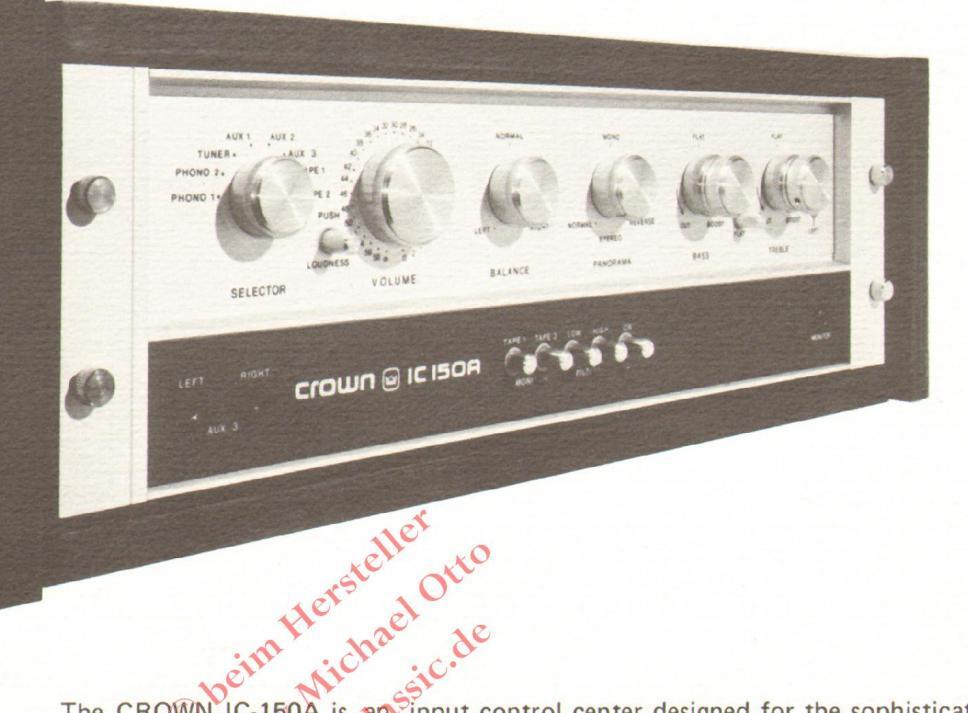
The CROWN IC-150A is an input control center designed for the sophisticated audiophile. It offers significant benefits to enhance virtually any music system.
EXTREMELY LOW PHONO DISTORTION
A new phono circuit incorporates an exclusive, complimentary parallel discrete input driving an operational amplifier output. The results are extremely low distortion, wide dynamic range and a noise level 85 db or more below a 10 millivolt input.
QUIET, UNDISTORTED HIGH LEVEL SECTION
The high level amplification section incorporates a new integrated circuit design which combines very low distortion with an unweighted hum and noise figure 95 db below the rated 2.5 volt output. Maximum output of 12 volts rms provides headroom to eliminate clipping distortion. Level attenuation is provided by a precision tracked step attenuator. A 31 position switch covers a range of 58 db (plus the "off" position) in 2 db steps, accurate to within ±0.2 db. The loudness compensation simulates the standard I.S.O. curves down to 60 phons. A switched 10 db output attenuator is provided for use with power amplifiers within level controls.
FULL CONTROL FLEXIBILITY
Tone controls allow independent channel compensation for program or environmental problems at the frequency extremes. A cancel switch may be activated by-passing the tone controls to obtain a flat response for comparison.
The panorama and balance controls offer further facilities for compensating balance or image problems occuring in the program material or caused by the acoustic environment. Continuously variable imaging from stereo through mono to reverse stereo is provided by the panorama control.
Two tape inputs are provided with front panel monitor buttons, while one of the auxiliary inputs is provided with front panel phone jacks. A stereo phone jack monitor output is also provided at the front panel. The phono and main outputs are capable of driving loads of 600 ohms and greater.
COMPLETE 3 YEAR WARRANTY
The IC-150A comes with a full warranty covering 3 years of parts, labor and round-trip shipping. Upon receipt of the warranty registration card from your dealer, CROWN will automatically send you the CROWN Care Card. This plastic, wallet-sized card is your warranty certificate. Embossed on it will be your name and current address, the model number of your new CROWN unit and the expiration date of the warranty on that product. When you need service for your unit from an authorized CROWN dealer, simply present your CROWN Care Card.
As well, each unit is accompanied by a proof of performance sheet showing actual specifications obtained in final factory checkout.
*The IC-150A may be rack mounted or, as shown, an optional cabinet is available.

IC-150A PREAMPLIFIER

Frequency Response
High level: ±0.6dB 3Hz-100KHz with high impedance load, ±0.1dB 10Hz-20KHz with IHE load: Phono: +0.5dB of BIAA.
Phase Response
High level: typically +1° to -12° 20Hz-20KHz with IHF load: Phono: typically ±5º 20Hz-20KHz additional phase shift
Hum and Noise
(20Hz-20KHz inputs shorted): Hi-level: 95dB below rated output (typically 105dB with IHF "A" weighted measurement). Phono: 85dB below 10mV input (typically 0.3uV input noise).
Distortion IM
Less than .002% at rated output with IHF load (typically under 0.001%).
Noise Transfer Intermodulation Distortion
High level: less than 0.012% at 2.5 volts peak equivalent output level. Phono: less than 0.007% at 2.5 volts peak equivalent output level. Test signal 10KHz-26KHz band limited white noise (crest factor 3.9); distortion products measured below 10KHz; NTIM testing is sensitive to audible products of high frequency distortion mechanisms such as
Distortion THD
Less than .0005% @ 1KHz, max. .05% 20Hz-20KHz at rated output with IHF load.
Six high level inputs (1 tuner, 3 auxiliary, 2 tape), two equalized phonos.
Input Gain & Impedance
Hi-level: 20.8dB +0.2dB 100K ohms nominal (25K ohms volume max.); Phono: 30-50dB (adjustable) 47K ohms. Sensitivity: 0.75mV @ 1KHz for rated output at maximum gain.

Phono Input Overload
33-330mV at TKHz, depending on gain (100mV when set at 60dB total preamp gain). Outputs N
12V maximum before overload, 2.5V rated, 600 ohms output impedance. Switched 0-10dB pad affects both sets of outputs Phono Output & Impedance
(At tape out) 600 ohms with typical maximum output of 11V RMS at 1KHz into high impedance load.
Monitor Output
Stereo, 3 circuit ¼" phone output, ahead of 0dB to - 10dB pad; output impedance 2.2K
Volume Control
Precision switched attenuator of 58dB (and off) dynamic range with calibrated tracking within ±0.2dB.
Loudness Compensation
New wide-range design for excellent simulation of I.S.O. curves down to 60 phons; with exclusive dual R/C bass-boost coordinated with volume attenuator.
Panorama Control
Unique continuously-variable control for infinite adjustment from stereo to mono to stereo reverse; replaces conventional stereomode switches and blend controls with an intuitive control of stereo spatial dimension.
Continuously variable ±15dB at 30Hz and 15KHz, cancel switch bypasses independent
Muting
Uses reed relay - removes turn-on transients from IC-150A output, thus protecting speakers.

Rumble: -3dB at 24Hz with 6dB-per-octave cut-off (volume attenuator at -20), Scratch: -3dB at 5KHz with 12dB-per-octave cut-off
AC Outlets
Total of six-five switched with 25A switch, one unswitched
Power Requirements
About 2 watts at 120V, or 240V, 50-400Hz
Semiconductor Complement
Five integrated circuits (equivalent to 89 bipolar transistors, 3 zeners, 12 diodes and 25 FETs) for a total of 96 bipolar transistors, 26 FETs, 4 zeners and 22 diodes.
Dimensions
19 inch standard rack mount. 5 1/4" H x 17" W: 8 1/8" behind panel.
Weight
10 lbs., with walnut cabinet 20 lbs.
Satinized aluminum front panel with charcoal gray suede textured lower panel.

1718 West Mishawaka Road Elkhart, Indiana 46514 219-294-5571 TWX 810-294-2160

IC-150A Vorverstärker
Das neue Systembauteil von AMCRON
Der IC-150A, das neue Systemteil von AMCRON, verkörpert eine zentrale Steuereinheit für den professionellen Einsatz ebenso wie für den kritischen Kenner und anspruchsvollen Musikfreund.
Für die Schallplattenwiedergabe haben wir mit diesem Gerät eine neue Schaltungskombination entwickelt, die darin besteht, daß über eine zusätzliche, parallel getrennte Eingangsstufe ein Operationsverstärker beschickt wird. Dank dieses Schaltsystems erreicht die IC-150A Vorstufe eine verschwindend geringe Verzerrung, ein besonders breites Frequenzband und einen Fremdspannungsabstand von 85dB oder besser bei einer Eingangsspannung unter 10mV. Für das Ohr bedeutet dies eine präzise und saubere Basiswiedergabe, authentische Klangqualität auch der vielschichtigsten musikalischen Passage bis hin zu den höchsten Frequenzen des Hörbereichs.
Auch für die Verstärkung der hochpegeligen Eingänge haben wir unsere integrierten Schaltkreise verbessert. Dies äußert sich auch hier in einem extrem niedrigen Verzerrungsfaktor: unbelastet liegt der Fremdspannungsabstand bei 95dB unter der Nenn-Ausgangsspannung von 2,5V. Die maximale Ausgangsleistung von 12V (RMS) bietet mühelos genügend Reserven zur Unterdrückung von Klirrfrequenzen.
Die Aussteuerung der Pegel erfolgt durch eine präzise abgestufte Dämpfung. Der Drehbereich, der sich auf 58dB erstreckt, ist in 32 Stufen aufgeteilt (zusätzlich einer Null-Steltung) und wird mittels eines Rasten-Drehknopfs in 2dB-Intervallen mit einer Genauigkeit von ± 0,2dB abgetastet. Pegelabweichungen zwischen den Kanälen bleiben in einer Toleranz von ± 0,2dB. Bis 60 Phon ist die physiologische Klangkorrektur exakt den I.S.O.-Normen angeglichen. Eine angeschlossene Dämpfung der Ausgänge (10dB) bietet weiteren Freiraum für die individuelle Steuerung der Pegel. Sie dient vor allem zur Unterdrückung von Nebengeräuschen für den Fall, in dem die AMCRON IC 150A Vorstufe mit Kraftverstärkern ohne Pegelsteuerung eingesetzt wird
Zur Kompensierung von qualitativ nicht einwandfreiem Tonmaterial oder auch zum Ausgleich räumlich bedingter akustischer Mängel können die Kanäle getrennt über eine Baß- und Diskantsteuerung abgestimmt werden. Durch einfachen Knopfdruck wird die frei- und nach individuellen Gesichtspunkten ausgesteuerte Diskant- und Baßabstimmung überbrückt, um in beiden Kanälen lineare Signalpegel herzustellen.

Über die Panorama- und Balance-Steuerelemente können Mängel am Klangbild – seien sie aufnahmetechnischen oder raumakustischen Ursprungs – ausgeglichen werden. Über die Panorama-Schaltung lassen sich die beiden Kanäle von normal Stereo über Mono bis zu vertauschten Seiten umkehren.
In den IC-150A können Signale von 2 Schallplattenspielern, 2 Tonbandmaschinen, 1 Tuner und 3 Zusatzelemente eingegeben werden. 2 Band-Eingänge lassen sich auf der Frontplatte über Monitor-Steuerknöpfe schalten. Einer der AUX-Eingänge ist mit einem Kopfhöreranschluß auf der Frontplatte ausgestattet. Ebenfalls auf der Frontplatte ist ein Monitoranschluß für Stereowiedergabe leicht zugänglich. Die Phono- und hochpegeligen Ausgänge können an Verbraucher mit einem Widerstand ab 600 Ohm angeschlossen werden.
Auf der Rückseite des IC-150A befinden sich 6 Netzbuchsen für den Betrieb weiterer Systembauteile – davon sind 5 an den IC-150A gekoppelt. Die gekoppelten Netzanschlüsse werden über einen 25 Ampère-Schalter versorgt, der beim Einschalten betätigt wird. Durch eine 5 sekündige Stummschaltung beim Einschaltvorgang werden die Lautsprechersysteme vor Überspannungen geschützt.
Sämtliche Bauelemente des IC-150A müssen unseren und Ihren hochgesteckten Leistungserwartungen für den Dauerbetrieb gerecht werden. In den, für die Vorverstärkung wesentlichen Schaltungen variieren die Kapazitäten unserer Widerstände um höchstens ein Prozent. Integrierte Schaltkreise und Transistoren werden vor der Fertigmontage einzeln geprüft. Vor dem Versand wird das Gerät einem sorgfältig ausgearbeiteten Testverfahren unterworfen. Dabei müssen die ermittelten Werte den von uns garantierten Werten entsprechen. Jedes unserer Geräte verläßt unser Haus mit einer Prüfurkunde, der unsere Kunden über die im Prüfungsverfahren ermittelten Meßdaten informiert.
Der IC-150A ist für den Einbau vorgesehen. Auf Wunsch ist ein Nußbaumgehäuse erhältlich.
IC-150A Technische Daten
O'Y
| Frequenzgang: |
hochpegelig: 3 Hz – 100 kHz ± 0,6 dB bei hohem Scheinwiderstand
10 Hz – 20 kHz ± 0,1 dB, IHF-Belastung phono: nach BIAA-Norm (50 Hz – 15 kHz) ± 0.5 dB |
|---|---|
| Phasenverhalten: |
hochpegelig: ± 1° bis -12° typisch bei 20 Hz - 20 kHz und IHF-Belastung
phono: 20 Hz - 20 kHz ± 5° zusätzliche Phasenverschiebung |
| Fremdspannungsabstand: |
20 Hz – 20 kHz, Eingänge kurzgeschlossen
hochpegelig: 95 dB unter Nenn-Ausgangsleistung (105 dB typisch bei A-Meßverfahren |
|
phono: 85 dB unter Eingangsspannung 10 mV (0,3 mikro V Rauschen am Eingang
typisch) |
|
| Klirrfaktor: |
gemessen bei Nennausgangsleistung 10 Hz – 400 Hz
kleiner als 0,002 % (kleiner als 0,001 % typisch) an IHF-Belastung |
| Intermodulation: |
(gemessen bei Nenn-Ausgangsspannung im IHF-Meßverfahren) kleiner als 0,002 %
(kleiner als 0,001 % typisch) |
| Harmonische Verzerrung: |
kleiner als 0,005 % bei 1 kHz, max. 0,05 % von 20 Hz bis 20 kHz bei Nenn-Ausgangs-
spannung an IHF-Belastung |
| Eingänge: |
6 hochpegelige Eingänge: 1 Tuner, 3 AUX (Reserve), 2 Tonband
2 entzerrte Phonoeingänge |
|
Eingangsverstärkung
und Impedanz: |
hochpegelig: 20,8 dB ± 0,2 dB, 100 kOhm nominal max. Lautstärke 25 kOhm
phono: 30-50 dB (regelbar), 47 kOhm Empfindlichkeit: 0,75 mV, 1 kHz für Nenn-Ausgangsspannung bei max. Ver- |
|
Maximale Eingangs-
spannung, Phono: |
nach Verstärkungsgrad unterschiedlich bei 1 kHz
33–330 mV (bei 60 dB Vorverstärkung 100 mV) |
| Ausgänge: |
Überlastungsfestigkeit unter Belastung an hohem Scheinwiderstand 12 V
Nennausgangsspannung 2,5 V bei 600 Ohm Ausgangsimpedanz die zugeschaltete 0–10 dB-Dämping wirkt auf sämtliche Eingänge |
| Phono-Ausgang und | bei typischer maximaler Ausgangsspannung von 11 V (RMS) und 1 kHz unter Belastung |
| Impedanz: et de |
an einem hohen Ausgangswiderstand beträgt die Ausgangsimpedanz 600 Ohm (Tape-
Taste auf "aus") |
| Monitor-Ausgang: |
vor der 0 dB- – 10 dB-Dämmung 3-smasiger Stereoausgang für Ø 6,5 mm Klinkenstecker
Ausgangsimpedanz pro Kanal 22 kOhm |
| Lautstärkerregler: | Präzisionsstufenschalter über einen Drehbereich von 58 dB (zuzüglich Null-Schaltung) in 2 dB Intervallen mit einer Genauigkeit von ± 0,2 dB |
| Physiologische | bis 60 Phon wird durch die neue "side-range" Technik eine weitgehende Annäherung an |
| Klangkorrektur: | den Verlauf der I.S.O. Kurve erreicht: eine zweifache R/C Tiefenanhebung ist mit der Lautstärkeregelung gekoppelt. |
| Raum-Klang-Regler | Einzigartiges Bedienungsinstrument zur stufenlosen Mischung der Kanäle von Stereo- |
| (Panorama): |
über Mono bis zum seiteneverkehrten Stereo. Durch unmittelbare Anpassung des Ste-
reoklangs an die räumlichen und akustischen Gegebenheiten können herkömmliche Ste- reo/Mono-Schaltungen entfallen. |
| Klangregler: |
30 Hz bis 15 kHz: ± 15 dB stufenlos regelbar. Überbrückungsschalter für spontane Her-
stellung linearer Signalpegel in beiden Kanälen. |
| Stummschaltung: | zum Schutze der Lautsprecher werden durch ein Reed-Relais Überspannungen beim Einschaltvorgang unterdrückt. |
| Filter: |
Rumpel: -3 dB bei 24 Hz (6 dB/Oktave), Lautstärkeregler auf 20
Rausch: -3 dB bei 5 kHz (12 dB/Oktave) |
| Netzanschlüsse: |
5 Wechselstromanschlüsse geschaltet (25 Ampère)
1 Wechselstromanschluß nicht geschaltet |
| Leistungsaufnahme: | an einer Wechselspannung (50-400 Hz) von 120 oder 240 V etwa 2 Watt |
| Halbleiterbestückung: |
5 integrierte Schaltkreise (entsprechen 89 doppelpoligen Transistoren, 3 Zenern, 12 Di-
oden, und 25 FETS). Das Gerät enthält 96 doppelpolige Transistoren, 26 FETS, 4 Zener und 22 Dioden. |
| Abmessungen: |
lichte Breite und Höhe für den Einbau 43 cm x 13,5 cm
Tiefe 21 cm |
| Gewicht: | 4,5 kg netto, mit Nußbaumgehäuse 9 kg |
| Finish: |
Frontplatte: halbmatt poliertes Aluminium
untere Blende: anthrazitgraue Kunststoffbeschichtung mit Wildlederstruktur |
| Vertretung für Deutschland |
Vertretung für Deutschland WESTEND SOUND GmbH Westendstraße 46 6000 Frankfurt 1
on the front panel that surround the knob; 0 dB, -10 dB, -20 dB, -30 dB, -40 dB and -50 dB. Since each vertical division on our spectrum analyzer corresponds to an amplitude difference of exactly 10 dB, you can see how extremely precise that master VOLUME control really is.
Using the IC-150A
Our overall comments concerning the performance of Crown's IC-150A will be performance of Crown's IC-150A will be sound along with an overall product analysis in Table II. Control action is smooth and positive, though we did run into a bit of frouble with the tone defeat switch on our sample, which seemed to exhibit an intermittency during its first few pushes. This problem cleared up by itself and may have been caused by a bit of dirt or dust that had gotten into the contacts during shipment and/or packing. While the front panel (and our description of it) seems devoid of any indicator lights, there is, in fact, a camoulaged red spot of light that seems to shine eight through the lower section of the panel when power is applied. In general, the IC-150A gives one a feeling of a total control sourd of controls, switches, and what have you. Such front panel simplicity and flexibility denotes a good sense of human engineering on the part of the designers of the IC-150A who are to be commended for improving upon their own earlier IC-150 which was a very fine beramplifigr-control unit to begin with. Br-E
| IA | BLE II |
|---|---|
| RADIO-ELECTRONICS | PRODUCT TEST REPORT |
| cturer: Crown International | Mode |
| OVERALL PRO | DUCT ANALYSIS |
| Retail price | $399.00 |
| gory | Medium |
|---|---|
| ormance ratio | Very Good |
| d appearance | Good |
| ality | Superb |
| al performance | Very good |
In our opinion, this excellent preamplifier-control unit from Crown should probably have been assigned a completely new model number, instead of the '4' which has been added on to the old IC-150 that has been, around for several years. The IC-150A is completely redesigned and, in many ways, runs rings around the older unit, which is no small accomplishment since the original IC-150 was a very fine preamp for its time. Hum-and-noise of the IC-150A is a good 5-dB lower than on the earlier unit, and distortion has been reduced by another order of magnitude, so that even our latest lab test equipment limits factual readings. We particularly liked the new step-calibrated master volume control with its 2-dB steps all the way down to -58 dB. The new loudness compensation circuitry is also an improvement, though we would have liked to see a few input level controls on the back panel so that it could be used more effectively. Welcome, too, are the high-current convenience outlets. Many preamps supply enough outlets for other equipment, but they usually cannot handle the power requirements of a basic amplifier that is likely to be used with a newerflifter of this binb nuality.
While it is difficult to discuss the "sound" of a preamplifier when it is being used with a basic power-amplifier (Who is to determine which of these components is ultimately responsible for what we end up hearing?), in our tests, using a Lux M-4000 to power a pair of Dahlquist DQ-10 speakers, sound was exceptionally transparent devoid of coloration and totally free of audible hum-and-noise. We are familiar with Crown's excellent amplifier, model DC-300A that is similar to their earlier DC-300 but with minor modifications incorporated to increase stability under unusual load conditions. The IC-150A, while representing a more major redesign effort, should make a perfect companion to that amplifier or to any other high-quality top-grade basic amplifier.
JRRENT PRICE: IC-150A $399.00
Redio-Electronics November 1976
REVIEWED IN KADIO-LIECTIONICS NOVEMBER 1976 Gernsback Publications, Inc. 1976 REPRINTED WITH THE PERMISSION OF THE PUBLISHER
Radio-Electronics Tests Crown IC-150A Preamplifier
Michael Otto
Archiv
ANYONE FAMILIAR WITH CROWN'S EARLIER model IC-150 will immediately realize that the new IC-150A is a totally redesigned unit, both in terms of front-panel arrangement and internal circuitry. The newer preamplifiercontrol unit, shown in Fig. I, is supplied with a vinyl-clad black wrap and can be operated free-standing. Additionally, it can be mounted in an optionally available wood cabinet, custom mounted in a cabinet panel of your choice, or rack-panel mounted by means of angle brackets and hardware supplied with each unit. When rackmounted, the unit is light enough so that no support shelf is required.
Major controls along the upper section of the panel include a SELECTOR switch (with two PHONO settings, a TUNER position and three AUX positions plus two TAPE positions), BALANCE control, dual-concentric BASS and TREBLE controls, a unique continuously variable PANORAMA control (that makes a smooth transition from stereo, to mono, to reverse
stereo) and a precision switch-type VOLUME control calibrated in 2-dB steps from 0 dB to -58 dB. A pushbutton located between the VOLUME and SELECTOR switches activates the loudness control circuitry, while a similar pushbutton between the BASS and TREBLE controls serves to bypass the tone control circuitry completely for absolutely flat
the lower, black section of the panel take care of two tape monitor circuits, low and high filters and the power on/off function. At the lower left are a pair of single-circuit phone jacks for front panel connection to the AUX 3 inputs, while at the extreme lower right is a stereo (two-circuit) phone jack for monitor output.
FIG
Hifiellas


than six convenience AC outlets are provided, five of which can handle a combined AC drain of 25 amperes. Input and output jacks are all mounted on a horizontal surface, but descriptive legends corresponding to these jacks are screened on the rear vertical surface for legibility. Near the pairs of PHONO inputs are screwdriver adjustment controls that permit you to vary the gain of the phono preamp section over a 20-dB range, with maximum sensitivity being 0.7 mV for rated output. In all of our subsequent tests, these controls were set to provide rated output (2.5 volts) from the main outputs with a phono input level of 2.5 mV. A slide-switch changes the gain by a fixed 10 dB.
Circuit description
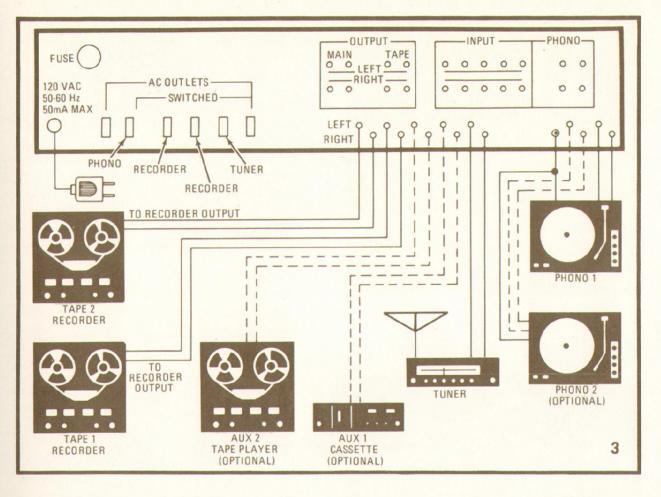
The number and type of equipment that can be connected to the IC-150A is extremely diverse. As illustrated in the connection diagram of Fig. 3, as many as four different tape decks could be used with the system, along with two turntables and a tuner. Only two decks could be monitored however if they are of the three-headed variety. Note.
MANUFACTURER'S PUBLISHED SPECIFICATIONS
Frequency Response: High Level: ±0.6 dB from 3 Hz to 100 kHz; Phono (RIAA): ±0.5 dB. Phase Response: High Level: +1° to -12°, 20 Hz to 20 kHz; Phono: ±5°, 20 Hz to 20 kHz. Hum and Noise: Phono: 85-dB below 10 mV input; High Level: 95dB below rated output. THD: Less than 0.0005% at rated output with 1-kHz input; 0.05% from 20 Hz to 20 kHz. IM Distortion: Less than 0.002%. Input Gain: Phono: adjustable from 30 to 50 dB; High Level: 20.8 dB ±0.2 dB. Phono Overload: 33 to 330 mV, depending upon gain setting of input. Output Level: 12-volts maximum before overload; 2.5 volts, rated. Tone Control Range: ±15 dB at 30 Hz (bass) and 15 kHz (treble). Filters: Rumble: -3 dB @ 24 Hz. 6 dB/octave; Scratch: -3 dB @ 5 kHz, 12 dB/octave. Power Requirements: 2 watts @ 120V or 240V, 50-400 Hz. Dimensions: 19-inches standard rack mount; 17 × 51/4 × 81/8-inches behind panel.
too, that since there are two pairs of main output jacks, signals could be fed to two separate stereo power amplifiers, if desired, or to a power amplifier and a headphone amplifier as shown in the connection diag-
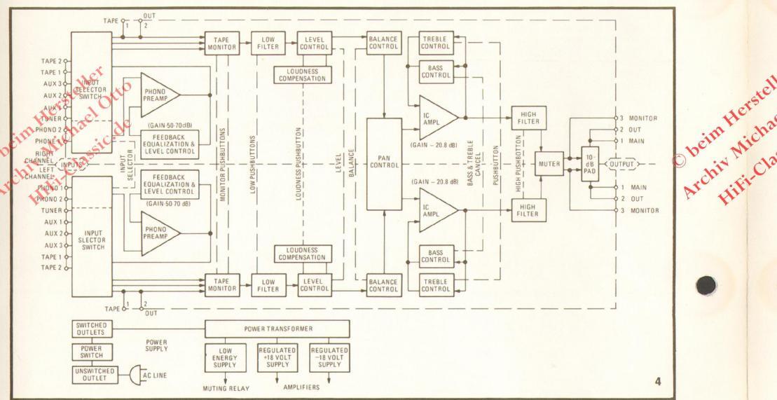
A signal-flow block diagram of the IC-150A is shown in Fig. 4. The electronics of the IC-150A are built around five integrated circuits that provide the equivalent of 89 transistors, 25 FET's, 3 Zener diodes and 12 diodes. In addition, 7 bipolar transistors, 1 FET, 1 Zener and ten diodes are used in discrete form. The output of the IC-150A is muted for several seconds after turn-on to protect speakers against "pops". The phonopreamplifier section employs a low-noise
complementary design, using an LM301AN operational amplifier IC. Tone control and voltage amplifiers are LF356H FET op-amp IC's: one per channel.
Two major circuit boards are used in the construction of the IC-150A: one containing the phono-preamp circuitry, the other for high-level amplification, tone control circuits and power-supply parts. The regulated power-supply delivers plus and minus 18 volts. The master VOLUME control is positioned directly following the high-level input circuits, followed by the BALANCE and PANO-RAMA controls that precede the tone control amplifier stages. The 10-dB output attenuator is in the form of a precision voltage-divider arrangement just preceding the actual output terminals. Muting relay contacts (that delay audio turn-on) follow all the active signalbandline elements of the circuit.
Laboratory measurements
A summary of our test measurements is shown in Table I and can be readily compared with manufacturer's claims. At mid-frequencies, the maximum output obtained before overload exactly equalled the 12.0-volts claimed. The harmonic distortion observed for rated output (2.5 volts) is undoubtedly produced by our signal source, which is known to contain around 0.002% THD. Thus, we cannot substantiate Crown's claim of 0.0005% for this specification. Obviously, at these distortion levels, the readings become a bit academic anyway since no noone is likely to hear this level of distortion under actual listening conditions. Note, however, that there is a tendency for THD to frequency end of the spectrum where we did measure 0.047% for rated output. The defendence of the spectrum where we did measure 0.047% for rated output.
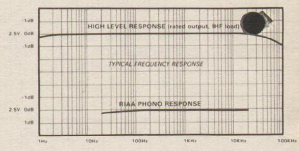
The phono equalization was accurate to within 0.4 dB of the RIAA curve, with maximum deviation occurring at the extreme low end of the audio spectrum. Our phono hum measurement of 72 dB is referred to an input sensitivity of 2.5 mV. Translated to a 10 mV input (as specified by Crown), the number becomes 84 dB, or within a hair's breath of the 85 dB claimed. Both Crown's claim and our measurements were made without any weighting network applied. Frequency response for the high-level inputs was within 1-dB from 4 Hz to 37 kHz, and hum-and-noise for these inputs was exactly 95-dB below rated output as claimed.
As stated earlier, all of our phono performance measurements were made with respect to a 2.5-mV input for an output of 2.5-volts (a total system gain of 60 dB), but we did check the range of the gain adjustments for phono and determined that overall gain could be varied from 70 dB to 50 dB so that the phono input-signals ranging from 0.79 mV to 8.0 mV could be adjusted to produce the rated output.
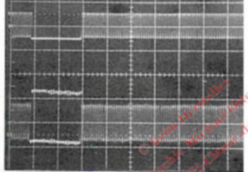
The range of the BASS and TREBLE controls are shown in the composite scope photo of Fig. 5, with a flat-response trace superimposed for reference. High and low filter response corresponds exactly to manufacturer's claims, with the rumble filter exhibiting a 6 dB-per-octave slope and the highcut filter attenuating frequencies above about 5 kHz at rate of 12 dB-per-octave.
Figure 6 serves to illustrate two important features of the IC-150A. First, of course, we see the loudness control compensation dB intervals. This loudness compensation differs somewhat from the so-called Fletcher-


Munson curves that have been traditionally used as a basis for loudness compensation at low listening-levels. These new curves are based upon more recent work by Robinson and Dadson (1956) which has been adopted by the International Standards Organization. Note, in particular, that no high-frequency emphasis is introduced at low levels, since very little of such emphasis was found to be needed for most listeners in the more recent investigations. In order to use this loudness control most effectively, it is necessary to calibrate your master VOLUME control on the IC-150A so that its maximum clockwise position corresponds to a listening level of around 100 dB SPL. Allowing for the many variables such as power amplifier gain, speaker efficiency and room size, this requires that all input program source levels be normalized in level to deliver that final sound pressure level. This is easily done with respect to phono program sources (thanks to the gain controls included for this circuit), but unless the amplifier used with the IC-150A has input level controls as well and unless your tuner and tape decks are equipped with output level controls, all the effort and precision built into this loudness compensation control may be for naught.
The second purpose served by the scope photo of Fig. 6 is to illustrate the precise calibration of the voLUME control of the IC-ISOA. We did not reduce this control by observing successive 10-dB reductions in output, but simply by reading the numbers
| TABLE I | Jers d | |
|---|---|---|
| RADIO-ELECTRONICS PRODU | CT TEST REPO | RTA hat |
| Manufacturer: Crown International | 10 | Model IC-150A |
| PREAMPLIFIER PERFORMANC | E MEASUREME | NTS |
| R-E | B.E | |
| OUTPUT VOLTAGE MEASUREMENTS | Measurement N | Evaluation |
| Rated output (volts) (per mfr.) | 2.5 | Excellent |
| 12.0 | Execution | |
| Harmonic distortion rated output 1 kHz (%) | 0.0025 | Superb |
| Harmonic distortion, rated output, 20 Hz (%) | 0.0035 | Superb |
| Harmonic distortion, rated output 20 kHz (%) | 0.047 | Excellent |
| IM distortion, rated output (%) | 0.0025 | Superb |
| IM distortion, 10-volt output (%) | 0.001 | Superb |
| Harmonic distortion, 10-volt output (1 kHz) | 0.0017 | Superb |
| PHONO PREAMPLIFIER MEASUREMENTS | ||
| Frequency response (RIAA ± dB) | 0.4 | Good |
| Maximum input before overload (mV) | 150 | Very good |
|
Hum/noise referred to full output (dB)
(at rated input sensitivity) |
72 | Excellent |
|
HIGH LEVEL INPUT MEASUREMENTS
Frequency response (Hz-kHz, ± dB) Hum/noise referred to full output (dB) Residual hum/noise (minimum volume) (dB) |
4-37, 1.0
95 95 |
Excellent
Excellent Very good |
| TONAL COMPENSATION MEASUREMENTS | ||
| Action of bass and treble controls | See Fig. 6 | Good |
| Action of low frequency filter(s) | See Fig. 7 | Very Good |
| Action of high frequency filter(s) | See Fig. 7 | Very good |
|
COMPONENT MATCHING MEASUREMENTS
Input sensitivity, abnon 1/phono 2 (mV) Input sensitivity, auxiliary input(s) (mV) Input sensitivity, tape input(s) (mV) Output level, tape output(s) (mV) |
2.5 / 2.5
230 230 230 |
See Text (Variable) |
| EVALUATION OF CONTROLS, | ||
|
CONSTRUCTION AND DESIGN
Adequacy of program source and monitor switching Adequacy of input facilities Arrangement of controls (panel layout) Action of controls and switches Design and construction Ease of servicing |
Very good
Excellent Very good Good Excellent Good |
|
| OVERALL PREAMPLIFIER PERFORMANCE RATING | Excellent |


 Loading...