

Page 1
Boiling Water Units
Features:
Automac lling.
Electronically controlled.
Economical to use.
Serviced without
removing the tap.
Boil dry protected
element.
Steam free operaon.
Available in white or stain-
less steel cover.
OPERATING & INSTALLATION INSTRUCTIONS
CELSIUS 100 BOILING WATER UNITS
MODELS: CRN2.5, CRN5, CRN7.5,CRN10, CRN15, CRN20, CRN25 CI & EI
Crown Celsius 100
PROUDLY MADE IN AUSTRALIA
Page 2
CROWN INDUSTRIES
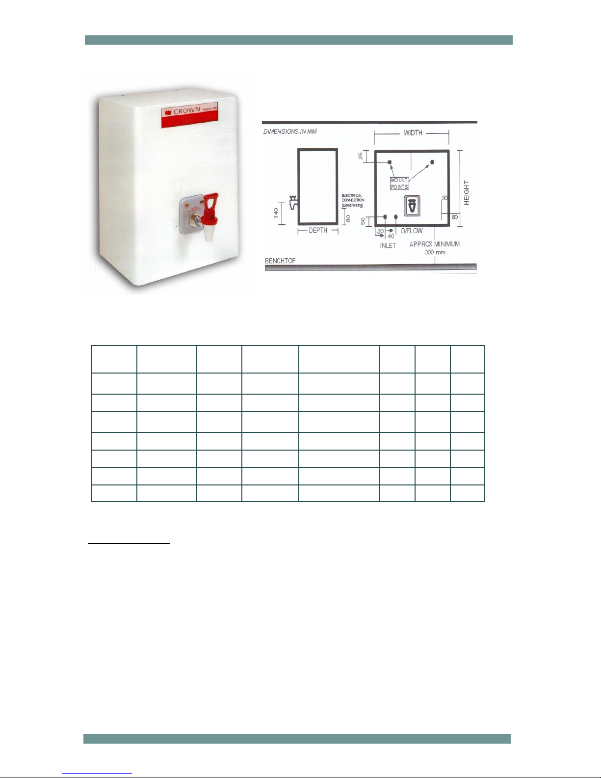
CELSIUS 100 BOILING WATER SYSTEM - SPECIFICATIONS
Optional Extras on:
To determine the right model for your requirements calculate the number of cups of boiling water
that would be required at any one time, then refer to the chart (above) for the corresponding model.
If you require a larger element specify this in the product order form. All models are supplied as
White powder coated finish unless Stainless Steel is specified.
WARRANTY 12 Months Parts and Labor against system failure.
M O D E L
NO
C A P A C I T Y
(LTS)
NO. CUPS
C U P / H R
RECOVERY
RATING KW & AMP HEIGHT WIDTH DEPTH
CRN 2.5 2.5 14 110 1.8, 10amp 365 320 220
CRN 5 5 25 110 1.8, 10amp 465 320 220
CRN 7.5 7.5 38 110 2.4, 10amp 480 350 250
CRN 10 10 50 110 2.4, 10amp 550 350 250
CRN 15 15 75 110 2.4, 10amp 640 400 300
CRN 20 20 100 110 2.4, 10amp 640 400 300
CRN 25 25 125 110 2.4, 10amp 735 400 300
Page 3

CROWN INDUSTRIES
PRODUCT GUARANTEE
These boiling water units are guaranteed for a period of one year from the date of purchase
against defects in materials and workmanship.
The guarantee will not apply to a product which has been subjected to misuse, bad water,
abuse, damage in transit, or improper voltage which would affect the reliability.
Filtration
We strongly recommend the fitting of a triple action inline filter to all boiling water units which
are being installed in hard water areas, especially W.A., S.A., N.T. and parts of Q.L.D. and
N.S.W. as some of these areas have a high concentrate of minerals and iron oxide in the water which are very harmful to the holding tanks etc.
Failure to fit adequate filters will void the warranty of the product.
Service
If this boiling water unit requires service of any kind just contact Crown Industries, direct on
Melbourne (03) 9739 6966 for your nearest supplier of service and spare parts.
(If the supply cord is damaged, it must be repaired by the manufacturer or its agent to avoid a
hazard)
Page 4

BOILING WATER UNIT INSTALLER INSTRUCTIONS CELSIUS 100 CRN CI & EI Series
POSITIONING THE UNIT
The unit should be mounted on a strong wall above a sink or draining board at a tap height most comfortable for people to use
Or approximately 40 cm above standard sink height, t tap supplied with teon tape and ghten in upright posion.
CONCEALED PLUMBING INSTALLATION
There is provision for water and electrical concealed installaon.
EXTERNAL PLUMBING
We recommend the plumber to use a tundish for the overow pipe and isolang valve for the water inlet.
FILTRATION
We strongly recommend the ng of a triple acon inline lter to all boiling water units which are being installed in hard
water areas, especially W.A., S.A., N.T., and parts of Q.L.D. and N.S.W. as some of these areas have a high concentrate
of minerals and iron oxide in the water which are very harmful to the holding tanks etc.
Failure to t adequate lters will void the warranty of the product.
ELECTRICAL CONNECTION
IMPORTANT: PLEASE CHECK THAT THE POWER POINT IS WIRED CORRECTLY WITH THE ACTIVE ON THE TOP LEFT HAND TERMINAL,
THE NEUTRAL ON THE TOP RIGHT HAND & EARTH ON THE BOTTOM TERMINAL. THE UNIT WILL NOT OPERATE CORRECTLY IF IT IS
INCORRECTLY WIRED.
This unit is supplied with a ex and plug, for xed wiring please use a registered electrician.
INITIAL OPERATING INSTRUCTIONS
Once the unit has been installed correctly, the following procedure, should take place.
1. Turn water on.
2. Turn power on.
3. Wait unl water reaches the minimum water level probe, usually a dribble will come out of the tap in the open posion.
4. Close the tap and while the unit is lling observe to see that there are no leaks of water; if so invesgate the reason why
and repair.
5. Once the maximum water level is reached the unit will stop lling, the element will heat the water unl it reaches 96°C,
and then the electronic controller will monitor the water at 96°C indenitely.
6. Test the operaon of the unit by leng some of the water out of the tap, which almost immediately turns the water valve
on leng water into the tank and raising the water level to the top probe.
7. Once the unit is working correctly, t the cover with the four xing screws and leave the instrucons with the owner.
ALTERNATIVE SHORTCUT FOR THE INSTALLER!
To reduce the set up me of the installaon a short cut be used to trick the microprocessor into thinking that the unit is full of
water even when it is virtually empty.
Firstly, turn on the water and power, wait unl the water dribbles out of the open tap, then close the tap and with a screwdriver
short the top probe out to the edge of the tank, the top probe being the probe with the black wire xed to it, immediately the water
valve will stop lling and the element will come on and heat the water, then the heat and ll cycle will start and nish when the
top probe is reached.
CROWN INDUSTRIES
Page 5

TROUBLE SHOOTING ACTION ONLY TO BE PERFORMED BY A QUALIFIED
PERSON
WE RECOMMEND THAT IF THE ABOVE SYMPTOMS AND
ACTIONS CAN NOT BE REPAIRED TO RING CROWN INDUSTRIES
FOR TECHNICAL ASSISTANCE ON MELBOURNE AUSTRALIA
61-3-97396966 OR CONTACT YOUR NEAREST
CROWN DISTRIBUTOR.
SYMPTON CAUSES ACTION
UNIT NOT HEATING BUT
POWER LIGHT ON.
VENT THERMOSTAT OPEN, DUE TO
OVER FLOWING OR OVER BOILING.
REPLACE VENT THERMOSTAT. IF
UNIT OVER BOILING, REPLACE
THERMISTOR. IF PROBLEM
PERSISTS REPLACE CIRCUIT BOARD.
UNIT NOT GIVING WATER
FROM THE TAP.
TAP BROKEN,
WATER NOT TURNED ON,
ELECTRIC INLET VALVE COIL BURNED
OUT, CIRCUIT BOARD FAULTY.
REPLACE TAP INSERT.
TURN WATER ON AND TEST UNIT.
REPLACE WATER INLET VALVE AND
TEST UNIT. REPLACE CIRCUIT
BOARD AND TEST UNIT.
UNIT NOT WORKING
PROPERLEY.
POWER POINT NOT WIRED UP
CORRECTLY
CHECK TERMINAL CONNECTIONS.
1. ACTIVE TOP LEFT TERMINAL
2. NEUTRAL TOP RIGHT TERMINAL
3. EARTH CENTRE TERMINAL
CROWN INDUSTRIES
Page 6

TO REPLACE THE CONCEALED ELEMENTS - 2.4kw HU036 & 1.5kw HU037
(Turn the power off and drain water first)
Disconnect the active and neutral wires at the terminal block which are connected to the
element.
Disconnect the solenoid valve silicone connecting hose at the solenoid.
Disconnect the vent silicone hose at the vent pipe on the tank.
Remove the silicone plug holding the thermistor in place, then remove the thermistor and
place away from the tank.
Disconnect the high and low water level probe wires on the top of the tank and push out
of the way.
Remove the three screws on the bottom side of the chassis which hold and locate the
tank, then lift the tank off the chassis onto a table or bench.
Remove the insulation from the top of the tank then remove the four nuts and washers
which hold the tank top in place, then remove the tank top and put it to one side.
Turn the tank upside down then mark with a texta the position of the clamp plate and element so everything lines up on the assembly procedure.
Undo the six clamp plate nuts evenly until they are all nearly undone then place one hand
inside the tank and hold the element while removing all the nuts and washers and clamp
plate then withdraw the element out through the top.
Installation of the new element is the reverse of the dismantling procedure only make sure
the element seal and the position of the element is situated correctly.
TO REPLACE THE CIRCUIT BOARD
Turn the power off then proceed to remove the three small fixing screws from the chassis
mount bracket on the back panel only.
Carefully remove the white multi plug at the top of the circuit board then remove the small
plug marked red for temperature sensor and the small plug marked black for water level
cables.
Carefully fit the plugs to the appropriate sockets on the new replacement circuit board and
proceed to screw the circuit board assembly onto the back panel.
Turn the power on at the power point then proceed to check the Boiling Water Unit for
correct operation ie; heating, filling and stand by.
CROWN INDUSTRIES
Page 7

TO REPLACE THE ELEMENT (SIDE ENTRY MODEL- CRNEI)
(Turn the power and water off first and unplug at the power point)
Open tap and drain water tank. Open drain cock (one turn only). Remove four screws
holding front cover and lift front cover off carefully.
Disconnect the active neutral and earth cables from the element and check continuity with
multi meter.
If boil dry thermostat is faulty replace it, and test unit.
If element is faulty slowly undo the six screws in opposite sequence and remove all the
screws. Then remove the element and gasket and inspect.
Make sure element flange is clean prior to inserting the new element, insert the new element
with the boil dry thermostat at the top and finger tighten the six screws and washers, then
tighten evenly all the six screws until the gasket is compressed and the screws are very tight.
Connect the cables back onto the element.
Testing Procedure,
Tighten drain cock, close tap, turn water on and turn power on, unit should start up and fill
with water until top probe is reached then unit will start heating, depending on size and litres
once the water has reached serving temperature the ready light will come on and stay on for
up to 10 minutes then when it settles down the unit will operate by power on for a few
seconds then off for 10 minutes etc.
TO REPLACE THE CIRCUIT BOARD
Turn the power off then proceed to remove the three small fixing screws from the chassis
mount bracket on the back panel only.
Carefully remove the white multi plug at the top of the circuit board then remove the small
plug marked red for temperature sensor and the small plug marked black for water level
cables.
Carefully fit the plugs to the appropriate sockets on the new replacement circuit board and
proceed to screw the circuit board assembly onto the back panel.
Turn the power on at the power point then proceed to check the Boiling Water Unit for correct
operation ie; heating, filling and stand by.
CROWN INDUSTRIES
Page 8

CROWN INDUSTRIES
FACTORY 47
70-72 CAVE HILL ROAD
LILYDALE VIC TORIA AUSTRALIA 3140
Phone: 61 3 9739 6966
Fax: 61 3 9769 6977
ELECTRICAL REPAIRS TO BE PERFORMED BY A QUALIFIED PERSON ONLY.
Wiring diagram for Celsius 100
 Loading...