

Page 1
XII Service and Maintenance
WARNING
• THE BOILER CONTAINS REFRACTORY CERAMIC FIBER, A POSSIBLE HUMAN
CARCINOGEN. USE A NIOSH APPROVED RESPIRATOR WHEN SERVICING
HIGH-TEMPERATURE INSULATION AND GASKET MATERIALS. WASH EXPOSED
SKIN GENTLY WITH SOAP AND WATER AFTER CONTACT. WASH EXPOSED
CLOTHING SEPERATE FROM NORMAL LAUNDRY.
• LABEL ALL WIRES PRIOR TO DISCONNECTION WHEN SERVICING CONTROLS.
WIRING ERRORS CAN CAUSE IMPROPER AND DANGEROUS OPERATION.
VERIFY PROPER OPERATION AFTER SERVICING.
• FAILURE TO MAINTAIN THE BOILER IN PROPER WORKING CONDITION MAY
LEAD TO FIRE, EXPLOSION, PERSONAL INJURY OR DEATH AND EXTENSIVE
PROPERTY DAMAGE.
• TURN OFF ALL GAS AND ELECTRIC POWER SUPPLIES TO THE BOILER BEFORE
SERVICING. CONTACT WITH OR RELEASE OF DANGEROUS FLAMMABLE
GAS, ELECTRICAL VOLTAGE, MOVING PARTS AND VERY HOT WATER UNDER
PRESSURE MAY CAUSE SERIOUS PERSONAL INJURY, PROPERTY DAMAGE OR
DEATH.
• LOCK ELECTRICAL BOXES AND GAS VALVES CLOSED TO PREVENT SOMEONE
FROM INADVERTENTLY RESTORING POWER OF GAS BEFORE THE HEATING
SYSTEM IS SAFE TO OPERATE.
• WATER LEAKS CAN CAUSE SEVERE CORROSION DAMAGE TO THE BOILER OR
OTHER SYSTEM COMPONENTS. REPAIR ANY LEAKS FOUND IMMEDIATELY.
The following routine maintenance should be performed on an annual basis:
1) Turn off electrical power and gas supply to the boiler
2) Inspect the ue passages for signs of blockage. If there is any carbon in the combustion chamber or the ue passages,
clean the heat exchanger before proceeding further. See the cleaning procedure below.
3) Remove all burners, noting the location of the pilot main burner. If burners show signs of deterioration, they should be
replaced (some discoloration around the burner ports is normal). Clean the burners by rst brushing the ports with a soft
bristle brush and then vacuuming out any debris through the venturi opening.
4) Remove any debris found in the combustion chamber, being careful not to disturb combustion chamber insulation.
5) Inspect the pilot assembly. Clean any deposits found on the electrode and grounding strap. The ideal gap between the
electrode and the ground strap is 1/8”. Inspect the porcelain for cracks or other deterioration. Replace pilot assembly if
deterioration is found.
6) Inspect the combustion chamber insulation for deterioration.
7) Inspect the ignition cable insulation for cracks or other deterioration. If deterioration is found, replace cable.
8) Reinstall burners, being careful to put the pilot main burner in its original location.
9) Inspect all boiler wiring for loose connections or deterioration.
10) Inspect the vent system:
• Make sure that the vent system is free of obstructions.
• Make sure that all vent system supports are intact.
• Inspect joints for signs of condensate or ue gas leakage.
• Inspect venting components for corrosion or other deterioration. Replace any defective vent components.
36
Page 2
11) Inspect the boiler and hydronic system for leaks.
12) Place the boiler back in operation using the procedure outlined in “Start-up”. Check the pilot line and any other gas pip
ing disturbed during the inspection process for leaks.
Heat Exchanger Cleaning Procedure
WARNING
SOOT DEPOSITS IN THE FLUE PASSAGES ARE A SIGN THAT THE BOILER MAY BE
OPERATING AT HIGH CARBON MONOXIDE (CO) LEVELS. AFTER CLEANING THE
BOILER OF SOOT DEPOSITS, CHECK THE CO LEVEL IN THE FLUE GAS TO INSURE
THAT THE BOILER IS OPERATING PROPERLY.
If it is necessary to check CO, use a combustion analyzer, or other instrument which is designed to measure
CO in flue gas. A CO “sniffer” designed for testing CO levels in ambient air cannot be used to check boiler combustion. Take a flue gas sample by inserting a sample probe through the draft diverter opening and into the flue
collector so that the sample is taken in the area directly over the heat exchanger. Do not take a sample until
the boiler has been firing for at least five minutes. A normal CO reading for an AWR series boiler is less than
50ppm (0.005%). A reading of more than 100ppm (0.01%) is indicative of a combustion problem.
Some causes of excessive CO include:
• Incorrectly sized main burner orifice for the altitude at which boiler is installed
• Crooked or out-of-round orifice holes (never attempt to drill orifice for this boiler in the field)
• Partially plugged flue passages
• Improper manifold pressure
• Foreign material in burner venturis or burner ports
• Leak in seal between flue collector and heat exchanger
• Inadequate supply of combustion air
1) Turn off electrical power and gas supply to the boiler.
2) Disconnect the damper and vent connector from the boiler.
3) Remove the top jacket panel. If possible, remove the rear and left side jacket panels
4) Remove the burners.
5) Disconnect the wiring at the blocked vent switch.
6) Remove the four #10 sheet metal screws holding the ue collector onto the block. Also remove the two #10 sheet metal
screws securing the ue collector to the rear jacket panel.
7) Remove the ue collector from the heat exchanger.
8) Carefully remove the ue collector gasket strips and set them aside.
9) Clean the ue passageways using a stiff bristle brush. Be certain that all foreign material is removed from the gaps
between the pins.
10) Clean the bottom surfaces of the heat exchanger.
11) Put a light in the combustion chamber and look through the ue passages from the top to verify that they have been
thoroughly cleaned.
12) Replace the ue collector gasket strips. If desired, RTV-732 silicone sealant with a 500F intermittent duty temperature
rating may be substituted for this rope gasket. The ue collector must be thoroughly sealed to the heat exchanger.
13) Reattach the ue collector.
14) Reattach all the jacket components.
15) Reinstall burners, being careful to put the pilot main burner in its original location.
16) Replace the blocked vent switch.
17) Reconnect the damper and vent system.
37
Page 3

XIII Troubleshooting
A. Before Troubleshooting
The following pages contain trouble shooting tables for use in diagnosing control problems. When using these tables the
following should be kept in mind:
1) This information is only meant to be used by a professional heating technician as an aid in diagnosing boiler problems.
2) Where applicable, follow all precautions outlined in the Section X (Start-up and Checkout).
3) In general, these tables assume that there are no loose or miswired electrical connections. Before using these tables inspect all electrical connections on the boiler to make sure that they are tight. Also, check the wiring on the boiler against
the wiring diagram in Figures 9.2 and 9.3. Ensure that incoming 120 VAC power polarity is correct and that the boiler is
properly grounded. Further, ensure that the control power supply is 24 VAC (minimum 18 VAC to maximum 30 VAC).
4) All controls on the boiler are tested at least once in the manufacturing process and a defective control or component is
generally the least likely cause. Before replacing a component, try to rule out all other possible causes.
5) When checking voltage across at wiring connectors (such as at the vent damper harness plug) be careful not to insert the
meter probes into the metal sockets. Doing so may damage the socket, resulting in a loose connection when the harness
is reconnected.
B. If Display is Blank
1) Check for 24 VAC on transformer secondary connections (screws to which blue and yellow leads are connected). If voltage across these screws is between 18 and 30 VAC, possible causes include:
• Loose connection at either plug or transformer end of transformer harness (blue/yellow harness).
• Defective transformer harness
• Defective boiler control
2) If voltage is less than 18VAC at transfer secondary, possible causes include:
• Service switch off
• Trip 120VAC breaker
• Miswired or loose connection in 120VAC boiler circuit.
• Loose connection inside J-box between transformer primary and 120VAC line.
• Defective transformer (possibly caused by short circuit in 24VAC wiring or additional loads connected to the trans-
former in the eld).
C. If Control Shows Err Code
Use Table 13.0 to help identify and correct the cause of the problem.
D. If Control Shows StA Code, but Other Problem Present
If no Err Code is observed (even after repeatedly pressing I to cycle through Operation Mode), use Table 13.1 to help iden-
tify and correct the cause of the problem.
38
Page 4
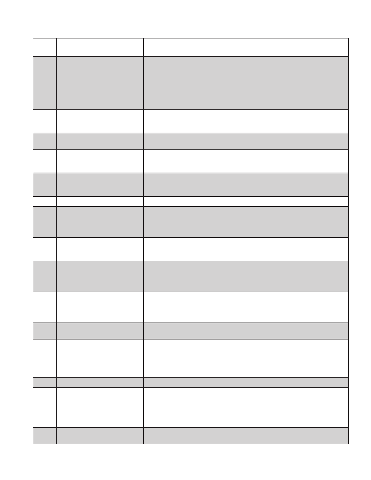
TABLE 13.0 - ERROR CODES
Error
Code Meaning Possible Cause
• Low gas pressure at gas valve inlet
• Partially plugged pilot tubing or pilot orice
• Loose connection in ignition cable or ground wiring
Low Flame Signal
4
Pilot Flame detected when no
6
ame should be present
Internal electronics failure
18
Flame sensed during 1.7s pre-
23
purge (before pilot valve opened)
Boiler water temperature sensor
32
failure
Duplicate Zone Error code reserved for future use
35
Damper failed to open after 60s
55
Grounded pilot electrode
57
AC Power Frequency Error
58
Line voltage error
59
(Supply voltage too high or low)
Thermostat input higher than
60
threshold
Line Voltage Unstable
61
Maximum recycles exceeded • See Error Code 4 above (boiler lost proof of pilot 6 times in a row)
63
Internal failure
64
EnviraCom communication lost
89
• Dirty pilot electrode/ground strap
• Pilot electrode porcelain cracked
• Damaged pilot hood/ assembly
• Defective control
• Defective gas valve
• High gas pressure
• Defective control
• Possible internal problem with boiler control. Cycle power to the boiler and
replace control if problem persists.
• Defective gas valve
• High gas pressure
• Defective control
• Loose sensor connection at control
• Defective Sensor
• Defective control
• Loose or defective damper harness
• Obstruction in path of damper blade
• Defective damper
• Defective control
• Condensate or foreign material is shorting pilot electrode to ground.
• Ignition cable insulation is damaged and touching ground.
• Pilot is damaged
• 120VAC power supply frequency is incorrect (Should be 60Hz)
• 120VAC power supply is dirty (consult electrician and/or Utility)
• Boiler water temperature sensor common (center wire) is damaged and
shorted to ground
• Power supply voltage is incorrect (should be 120VAC nominal)
• Defective or incorrect 24VAC transformer
• Loose 120VAC connection or 24VAC connection between transformer and
control
• External voltage is applied to thermostat connections (most common cause is
external transformer in old thermostat wiring.
• 120VAC power supply is dirty (consult electrician and/or Utility)
• Loose 120VAC connection or 24VAC connection between transformer and
control
• Large electrical loads elsewhere on the installation are switching on and off,
causing incoming voltage to swing excessively at boiler.
• Loose or defective damper harness
• Obstruction in path of damper blade
• Defective damper
• Improper pilot operation
• If problem persists, replace control
Communication lost between boiler control and certain Crown control options.
Consult Crown control option manual.
39
Page 5

TABLE 13.1 - FAULTS WITHOUT ERROR CODE PRESENT
Displayed
Codes Problem Possible Cause
StA 1
tt OFF
dh OFF
Burners and
Circulator Off
• Thermostat/s not calling for heat
• Loose connection in thermostat, zone valve end switch, or zone panel wiring.
• Thermostat, zone valve, or zone panel miswired
• Defective thermostat, zone valve, or zone panel
StA 1
tt On
tt On
dh On
StA 15
StA 6
StA 6
StA 6
STA 8
StA 10
StA 10
or StA 13
Burners Off
Circulator On
Boiler Warm
Heating
Circulator Off
DHW
Circulator Off
Burners Off
and Damper is
closed.
No spark at
pilot
Spark, but no
pilot ame
Pilot ame
present, but
spark does not
shut off
Pilot ame
present, spark
off, but Main
Burner does
not light at all
Main burner
lights, but
shuts off
immediately
No spark or
pilot
• Boiler off on high limit (normal operation)
• Boiler off on thermal purge (normal operation - See Table 11.6)
• Heating Circulator is being forced off on DHW priority (normal operation if Pt=ON -
see Table 11.7).
• See causes for “DHW Circulator off “ below
• Loose connection in circulator wiring
• Defective circulator
• Circulator is running, but system problem is preventing circulation
• Limit or LWCO connected to Option Plug #1 is open.
• No option is connected at Option Plug #1 and jumper plug (PN 9601830 ) is missing.
• Blocked vent switch (BVS) open due to problem with vent system, such as a blocked
chimney, or a combustion air supply problem. Correct and press reset button on BVS.
• Flame roll-out switch (FRS) open due to blocked heat exchanger. Correct problem and
replace FRS with exact replacement (see parts list)
• Loose connection in ignition cable or pilot ground
• Damaged electrode porcelain or ignition wire insulation (replace pilot)
• Pilot electrode or Ground strap damaged (replace pilot)
• If you cannot hear spark at all , replace control
• Low inlet gas pressure
• Plugged, kinked, or leaking pilot tubing
• Plugged pilot orice
• Gas line not purged of air
• Defective pilot assembly
• Defective gas valve (before replacing, conrm that there is 24VAC between PV and
MV/PV. If there is not, control harness is loose or the control itself is defective).
• Loose connection in harness between control and gas valve.
• Low inlet gas pressure
• Partially plugged, kinked, or leaking pilot tubing
• Partially plugged pilot orice
• Loose connection in ignition cable or pilot ground
• Damaged electrode porcelain or ignition wire insulation (replace pilot)
• Pilot electrode or Ground strap damaged (replace pilot)
• Defective Control
• Loose connection in harness between control and gas valve
• Defective gas valve (before replacing, conrm that there is 24VAC between MV and
MV/PV. If there is not either there is a loose connection in the control harness or the
control itself is defective).
• Low inlet gas pressure
• Partially plugged, kinked, or leaking pilot tubing
• Partially plugged pilot orice
• Pilot was either never established or proof of pilot was lost after it was lit. Cycle power
to the boiler and look for symptoms above.
40
 Loading...