

Page 1

Page 2
Page 3

products
®
Signature Series amplifi er is the
®
1
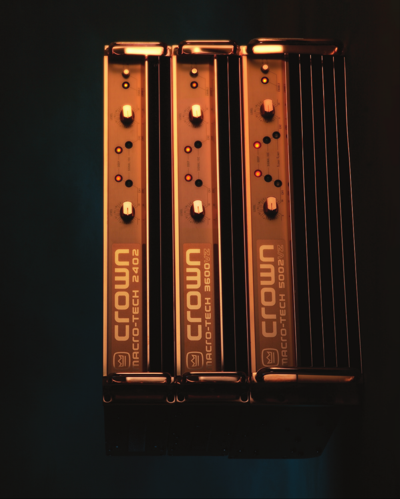
Macro-Tech Series
Celebrating the Crown
our Macro-Tech
culmination of a long heritage of Crown
and design ideas that began in the early 1970s.
Y
In these pages you can explore how the Macro-Tech Series
came to be, understand its advanced features, and enjoy
stories and sales literature from its colorful past.
Page 4
the most accurate reproduction of an audio signal you’ve ever
heard. And because we put the quality of sound above all else,
Crown amplifi ers are the most coveted in the business.
When it comes to manufacturing amps, our work is based on
one simple fact: there are no shortcuts to quality. And our Macro-
Techs have proven this time and time again in some of the most
demanding applications in the world.
For this special, limited Macro-Tech release, we wanted to bring
you more than just the typical operation manual. This brochure
goes much further, delving into the Macro-Tech’s development,
design philosophy, and advanced technical features. We’ve also
included some brochures from the past, a bio of Crown’s chief R&D
engineer Gerald Stanley, customer statistics, anecdotes and more.
, sparked
®
Macro-Tech Series of power amplifi ers.
®
Enjoy!
ometimes a product fi ts an application so well, it
is deemed a classic. The term is synonymous with
the Crown
S
Crown Macro-Tech Series
That product line, and its predecessor Micro-Tech
innovative technologies that provided lower distortion, less
thermal stress, higher output power, greater reliability, more
power density and superior audio quality.
No compromises, no gimmicks. Just brilliant engineering
backed by superior manufacturing, support and an
unsurpassed commitment to quality.
Like all Crown amps, the defi ning characteristic of the Macro-
Tech Series is sonic accuracy. A tight, rock-solid low end, with
smooth, detailed highs and a well-defi ned midrange. In short,
Since 1984, Crown has shipped
approximately 272,625 MT and MA
amplifi ers to date. That’s approximately
54 million watts into 4 ohms or 65
million watts into 2 ohms!
2
Page 5
3
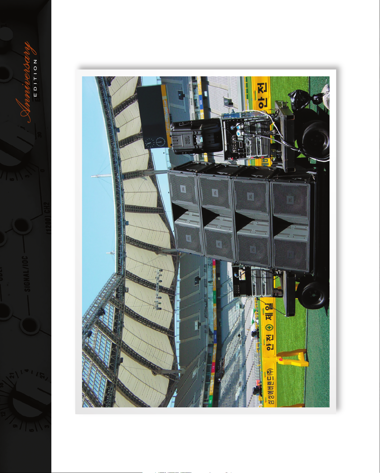
Crown Macro-Tech amplifi ers were used at the 64,640-seat Sangam Stadium in Seoul, South Korea, during the 2002 World Cup.
Page 6
TOUR
Neil Diamond tour
Pro Show, SPL Sound, XFL
Seoul Word Cup 2002
THEME PARK
Universal Studios
Everland (Korea)
Six Flags of America
Audio Analysts
Morgan Sound
Clair Brothers
Disturbed (band)
FIXED INSTALL
Club Capitale
Sydney 2000 Olympics
Crystal Cathedral
Art Garfunkel Tour
Maryland Sound
Gemini Sound
On Stage Audio
Offi cial All Star Cafe
Hard Rock Live
Experience Music Project
Spirit, Roxy
Enterprise Live
Deep night clubs
A Sampling of Crown Macro-Tech Users
STADIUM / ARENA
American Airlines Arena
American Airlines Center
Ralph Engelstad Arena
Key Arena
Xcel Energy Arena
Conseco Field House
Coors Field
Volkswagen Stadium
Hong Kong Stadium
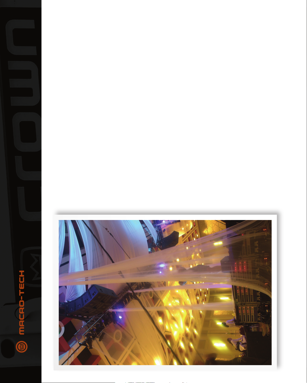
Racks of Crown Macro-Tech amplifi ers power this 2001 extravaganza staged in Salt Lake City’s Salt Palace for the Annual
Gala held by Utah Governor Mike Leavitt. Rocky Mountain Audio Visual chose Crown Macro-Tech along with JBL Vertec
speakers to provide concert-quality sound for the event. (Find out more at http://www.jblpro.com/pressroom/rmav_utah.htm.)
4
Page 7
5
Crown Macro-Tech amplifi ers power the premium sound system employing JBL PD Series speakers in the 400,000 sq. ft. Ralph Engelstad Arena in Grand Forks, North Dakota.
Page 8

How It All Began...
The brainstorming for this whole family began with
collaboration between engineers Gerald Stanley and Jim
Wordinger. In considering the drawbacks of current power
amplifi ers, they were looking for ways to:
• pack more power into a smaller rack space
• improve reliability by preventing overheating
• lower the cost per watt.
Gerald’s Grounded-Bridge design and Junction Temperature
Simulation were already in his toolkit. In 1975, JTS was
employed in the SA-2 and PSA-2 amplifi ers, while Grounded
Bridge was used in the M-600.
Gerald and Jim thought, “How about taking our two best
technologies and putting them in the same product?” The
Micro-Tech Series was born. The original name of this series
was to be HVA for High Value Amplifi er.
), protected
®
power supply, also called bi-level
®
, awed the audio industry with new
®
™ topology provided 4 times the power of
technologies that reduced distortion and thermal
he Macro-Tech product line, and its precursor
Micro-Tech
existing power transistors without sacrifi cing reliability.
stress — while increasing reliability, audio quality, power density
and power output.
Three patented technologies invented by Crown’s Gerald Stanley
led to those benefi ts:
The Macro-Tech Design Philosophy
T
• Grounded Bridge
• Junction Temperature Simulation (JTS), otherwise known
two best
taking our
How about
and putting
technologies
as Output Device Emulator Protection (ODEP
the power transistors from overheating and maximized their
potential power output by keeping them at the optimum
temperature.
them in the
same product?”
power-supply switching, was used in the MA-3600VZ and MA-
5000VZ Series. The supply changes its impedance to adapt to
the signal voltage and current. This technology permits large
amounts of power in a compact package while achieving ultra-
low distortion and without generating excess heat.
• Variable Impedance or VZ
6
Page 9
In those days, Crown was
recognized as a manufacturer
of home hi-fi products. But the
HVA Series was intended for
pro audio Touring and MI, not
for the living room. It was a new
direction for Crown.
Crown’s president at that time,
Max Scholfi eld, recognized that
Crown’s marketing needed to
be shaken up, so he hired Dr.
Clay Barclay to drive change
in Crown’s marketing and sales
divisions. Clay realized that
the MI and Touring industries
needed a product like this, and
he sold the idea to Crown and
to potential customers.
7
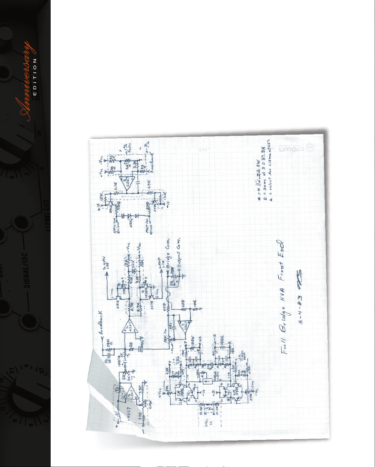
A 1983 schematic by Gerald Stanley of the Grounded Bridge circuit.
Page 10

An early sketch by Jim Wordinger
showing a proposed chassis layout
of a pre-Micro-Tech power amplifi er.
The MT-700 (never released) was the fi rst Micro-Tech amp. Then
came the MT-1000 which provided 1000 watts into 2 ohms. Next
was the MT-1200 which produced 1200 watts, thanks to bigger
power transformers.
The technology in Micro-Tech products helped Crown develop
amps for Magnetic Resonance Imaging (MRI). General Electric
asked Crown to make amplifi ers with more voltage and current
than what was available. We created bigger amps for GE, such as
the 7780, using JTS and Grounded Bridge.
Micro-Tech
Jim and Clay used to share ideas over lunch, where Jim told Clay
about the concept. Clay came up with the name “Micro-Tech”
because the goal was to put high technology into a micro-sized
amp. It was a new packaging paradigm as well as a new market.
In the early 1980s, Jim Wordinger went to Showco, one of the
major touring sound companies. At that time they were doing
sound for David Bowie using PSA power amps. According to
Jim, “We asked them what they would like to see in an amplifi er.”
“They said, ‘We’d like them smaller and lower-cost.’ I couldn’t
say anything about what we were working on, but their comment
certainly vindicated our design goals. Showco was one of
our fi rst customers; they used a lot of Micro-Techs. We had a
relationship with them. They would fi nd any problems fi rst and
then we’d fi x them.”
Eventually Clair Brothers bought Showco. Now they are using
over 2000 MA-3600VZs.
8
Page 11

Crown Macro-Tech 10,000.
9
two-thirds of the midrange drivers because
they weren’t used to seeing that kind
of power. Crown shipped in 24 drivers,
installed them, and wired them differently.
Problem solved. That’s the kind of support
Crown would do.”
...they weren’t
used to seeing
that kind of power.”
™ cards) and offered a better appearance.
“We supplied the fi rst Macro-Tech
prototypes to John McBride of MD
Systems, doing a tour for Garth Brooks.
At one gig, the FOH engineer noted that
he had to keep pushing the level up in
the midrange. The problem wasn’t with
the amps. Actually, MD had burned up
It was developed for John Royer and
Tom Allebrandi who did sound for the
Indianapolis 500. Three of these amps
were modifi ed to drive the race track’s
240V distributed-speaker system —
replacing two huge war-surplus amplifi ers
from a battleship.
Macro-Tech
Building on our experience with the MT series, Gerald and
Jim developed the Macro-Tech Series in 1987. It added Plug-
In-Processors (PIP
Jim Wordinger remembers, “In the early days we’d compare
MA amplifi ers side-by-side with competitive amps. Ours had
more punch and deeper bass, which I attributed to more output
voltage and current.”
The huge Macro-Tech 10,000 amplifi er was basically an MRI amp
modifi ed for audio use with a new audio interface and front panel.
Page 12

amp Crown ever made. Around 1992, Crown introduced the
MA-24x6 and MA-36x12 amps with a different power rating
in each channel for bi-amping woofers and horn drivers.
VZ technology (with bi-level power supply switching) was fi rst
prototyped in an MA-1200. It was feared that the switching
would affect the audio, but that did not happen. The fi rst
bi-level amps were MRI units custom-made for Picker
International, a medical imaging company.
Jim Stembel, Crown’s International Business Development
Manager, recalls: “At the trade show in which we introduced
the MA-3600VZ, it was the fi rst amp with that much power in
two rack spaces. One of our biggest competitors asked, ‘Why
put all that power in two rack units?’ We replied, ‘Because
we could.’ That power density was unheard of at the time. It
was quite a signifi cant landmark.”
“When we introduced the MA-5000, one of our major
customers asked, ‘Why does anybody need that much
power?’ Again it was an amplifi er ahead of its time — it
was so large compared to anything else on the market. At
the time, nobody appreciated the power of the MA-5000.
Of course, the MA-5000 has gone on to become a wildly
successful amp in touring sound — a standard. They really
were trend-setting amplifi ers.”
10 years ago in Pro Sound News, a poll reported that 9 out
10 of the major tours used Crown, mostly MA amps. We still
have die-hard customers who refuse to use anything else.
So, starting with Grounded Bridge, invented in 1971, and
JTS, invented in 1974, those two key pieces of technology
enabled the Micro-Tech and Macro-Tech family. After a long
lifetime, most of those products are still running. That’s what
we think they should do.
MA-5000s are used on
™, used the same main board as the
destroyers and aircraft carriers.”
In 1992, Crown engineer Andy Archias worked on
the MA-5000. Crown’s upper management was
delighted that the amp had such a positive impact
on the company, the music industry, and the audio
world. MA-5000s were even used on destroyers
and aircraft carriers (and still are today).
A major supporter of MA amps was Sam
Helms, manager of Sigmet, a premier pro audio
representative in New Jersey. Sam put Crown
amps through all sorts of torture tests. As he
says, “We put low-frequency square waves into
the amp and drove a subwoofer with that signal.
This was to show how the MA’s damping factor
controlled speaker-cone motion compared to the
competition. It was no contest.”
“Using a signal generator, we put 60 Hz in the
front end of the amp, ran the level controls up, got
high-power out of the amp and welded pieces
of metal with it! Or we’d take an AC cord, cut off
the end of it, put on a banana jack, plug it in the
back of the amplifi er, and run a drill off it. The
competition would shut off and the Crown amp
would just keep going. You could drill through a
4x4 with no problem at all.”
Crown’s elite studio amplifi er, the Macro-
Reference
MA-3600VZ, but with remote load sensing for
higher damping factor. It was the best-measuring
10
Page 13

11
Crown’s Vice President of Research and Development, Gerald Stanley.
In an era of
cookbook
designs and buggy
software, it would
seem that the most
basic lessons of
history have been
forgotten. Crown’s
recipe is simple:
design, build and
service each product
as if you were the
customer. This
approach not only
drives the product to
excellence, it drives
the people to be the
Gerald comments on Crown’s
success over the years:
he mastermind behind the Macro-Tech Series, and
all Crown solid-state electronics for over 40 years,
is our senior vice president of R&D Gerald Stanley.
best that they can be.”
Gerald recalls, “When I was a kid I used to go around to
neighbors to get old radios. I liked to get parts out of them, and
I liked to soup them up.” This early interest in electronics led to
an amazing career.
This brilliant engineer joined Crown part-time in 1964, fi rst
working as a tape-recorder tech, draftsperson and engineer,
About Gerald Stanley
T
when he designed the SA-20-20 and SA-60-60 — the fi rst
solid-state Crown amplifi ers. In 1965 he received a BSE from
Michigan State (Honors College) and MSE from the University
of Michigan in 1966 (State College Fellowship).
Gerald has this to say about the SA-60-60: “It was a dual 60W
8-ohm amplifi er. Only a few were made. They were unreliable,
using only high-speed fuses for protection. The SA-20-20 was
a 1-rack-space amp that soon became the SA-30-30. The SA-
20-20 used smaller versions of the SA-60-60 output devices.
The 60-60 was DC coupled throughout and the 20-20 was AC
coupled at the input. The DC-300 was not the fi rst DC audio
amp, but it was the fi rst that was reliable.”
Gerald went on to invent the technology behind all of Crown’s
power amp series. He holds a huge number of patents: 31 in
the U.S. alone, and many more in other countries.
Page 14

circuitry to simulate the instantaneous operating conditions of
those output transistors. Its name describes what it does: Output
Device Emulation Protection or ODEP. It not only simulates the
operation of the output transistors but it also compares their
operation to their known SOA. If more power is about to be asked
of the output devices than they are capable of delivering under
the present conditions, ODEP immediately limits the drive level
until it falls within the SOA. Limiting is proportional and kept to
an absolute minimum — only what is required to prevent output
transistor damage.
When ODEP limiting begins, the IOC circuitry will see that the
input waveform does not match the output waveform, and an error
(Input Output Comparator)
®
Macro-Tech Advanced Features
The Macro-Tech Series employs a number of innovative, patented
technologies. Let’s look at them in detail.
IOC
The IOC circuit compares the output signal of the amplifi er with
the input signal. If there is any difference other than gain, then it
is considered distortion and the IOC indicator fl ashes. This LED
lights whenever there is distortion of 0.05% or more. (Note that
amplifi er clipping is typically close to 3% THD.) An IOC condition
also is sensed by an IQ-PIP module installed in PIP-compatible
amplifi ers.
IOC is designed to report any form of distortion. IOC not only
signal is generated. If the compressors are on, they will see the
error signal and compress the input signal to correct the problem.
When this happens, there is no audible signal degradation.
Compression is subtle, and not noticeable unless the system is
driven to extremely high levels.
How does ODEP limiting increase the effi ciency of the output
transistors? It keeps them at the optimum temperature.
The transistors are neither overheated, nor overprotected.
Overprotecting results in transistors not being driven to their full
output level.
Gerald invented ODEP to solve two long-standing problems with
amplifi er designs:
checks the waveform for distortion, but also reports input
overload and even a protective action that mutes or shuts down
an amplifi er. With all of these features, IOC monitors the entire
amplifi er. When the IOC indicator is off, the amplifi er is defi nitely
operational and undistorted. IOC provides a real-time proof of
Output Device Emulation Protection (ODEP)
performance.
In short, ODEP enables the amplifi er to use the output transistors
more effi ciently while greatly increasing their reliability.
Finally, the status of ODEP is monitored in two ways. First, the front
panel ODEP indicators show whether the amplifi er is functioning
correctly or if ODEP is limiting the drive level. Second, ODEP data
is fed to the PIP connector at the back of the amplifi er so advanced
• Preventing amplifi er shutdown during demanding operation, and
• Increasing the effi ciency of the output transistors.
ODEP limits the signal when necessary to prevent overheating
and failure of the amplifi er output transistors. Crown engineers
established a rigorous program to measure the safe operating
area (SOA) — related to temperature — of each output transistor
before installing it in an amplifi er. Gerald also designed intelligent
One of Gerald Stanley’s many patents.
12
Page 15

13
Grounded Bridge theory
for electronics-savvy readers
The power-supply bridge rectifi er is not ground
referenced, and the transformer secondary is not center-
tapped. This allows the power supply to deliver +VCC
and -VCC from the same bridge rectifi er and fi lter as a
total difference in potential regardless of their voltages
with respect to ground.
Composite output devices are arranged to function as
gigantic NPN and PNP devices. Each output stage has
two composite NPN and two composite PNP devices.
The devices connected to the load are referred to as
“high-side NPN and PNP” and the devices connected
to ground are referred to as “low-side NPN and PNP.”
Positive current is delivered to the load by increasing
conductance simultaneously in the high-side NPN and
low-side PNP stage, while decreasing conductance of
the high-side PNP and low-side NPN in synchrony.
Imagine a graph of current versus voltage (I versus V) in
an output stage of a power amplifi er. This graph has four
quadrants: +V and +I, -V and +I, –V and –I, +V and –I.
Grounded Bridge is a four-quadrant amplifi er topology.
Resistive loads only use the fi rst and third quadrants (+V,
+I and -V, –I). Reactive loads also use the second and
fourth quadrants (–V, +I and +V, –I).
amplifi er designs, averaging
only 20%. Because of this,
Class A amplifi ers are large,
heavy and run very hot.
That is because the amp
runs constantly at full power.
On the other hand, Class A
Crown’s Grounded Bridge topology makes the amplifi er deliver
PIP modules like the IQ-PIP-USP3 can use it to make decisions and
control the amplifi er. With ODEP you get the maximum power with
the maximum protection — the show goes on!
peak-to-peak voltages to the load that are twice the voltage seen
Grounded Bridge
designs have the least amount
of distortion.
Class B operation is the
opposite of Class A. Both
output devices are never
allowed to be on at the same
time. The bias is set so that
current fl ow in a specifi c
output device is zero when
not stimulated with an input
signal. Each output device
is on for exactly one half of
a complete sinusoidal signal
cycle. Due to this operation,
Class B designs show high
effi ciency, but poor linearity
around the crossover region.
by the output devices and twice the voltage generated by the
power supplies. In other words, the amplifi er can produce louder
sound without stressing the output transistors. The results are
higher effi ciency, lower distortion and superior reliability.
Class AB+B
Crown invented the Class AB+B amplifi er design, which provides
both high effi ciency and low distortion. AB+B circuitry draws
less AC power and wastes less heat than Class A, and has less
distortion than Class B or Class AB. To explain how AB+B works,
fi rst we need to explore other amplifi er classes.
Audio power amplifi ers are classifi ed primarily by the design of
the output stage (the transistors and related circuitry that send
signals to the loudspeakers). Classifi cation is based on the
amount of time the output devices (power transistors) are made
to operate during each cycle of the signal. Amplifi er classes are
also defi ned in terms of output bias current (the amount of current
This is because it takes time
to turn one device off and the
other device on, causing extreme crossover distortion. All of
this restricts Class B designs to applications with low power
consumption, such as battery operated two-way radios and
other communications equipment.
fl owing in the output devices with no signal present).
In Class A operation, both output transistors conduct continuously
for the entire cycle of signal swing, so the bias current fl ows
in the output devices at all times. Both devices are always on.
Class A amplifi ers are single-ended designs with either PNP or
NPN output devices. Class A is the most ineffi cient of all power
Page 16

An amplifi er power supply must be large enough
to handle both the maximum voltage and
maximum current the amplifi er needs to drive
its rated power into a specifi ed load. In order
to meet this requirement, most conventional
supplies are heavy, large, and produce lots
of heat. In contrast, the VZ supply gets more
current AND voltage out of a smaller, lighter, and
more effi cient package by dynamically adapting
to both signal and load requirements in real-
time. This provides the best power match to the
Class AB operation allows both devices to be on at the same
time (as in Class A), but just barely. The output bias is set so
that current fl ows in a specifi c output device appreciably more
than a half cycle, but less than the entire cycle. That is, only a
little current is allowed to fl ow through both devices — unlike the
complete load current of Class A designs — but enough current
to keep each device operating so they respond instantly to
input voltage demands. Thus the inherent non-linearity of Class
B designs is eliminated, without the gross ineffi ciencies of the
Class A design. It is this combination of good effi ciency (around
50%) with excellent linearity that makes Class AB the most
widest range of loads.
The VZ power supply is divided into two
segments. When the output stage requires high
voltage, the segments are arranged in series to
deliver twice the voltage of a single segment.
When the output stage requires high current,
the segments are arranged in parallel to deliver
twice the current of a single segment.
Sensing circuitry “watches” the voltage of the
popular audio amplifi er design.
Class AB+B design involves two pairs of output devices. One
pair operates Class AB, while the other (slave) pair operates
Class B. Class AB+B designs are just as effi cient as Class AB,
but have even less distortion.
To summarize, AB+B circuitry draws less AC power and wastes
less heat than Class A, and has less distortion than Class B or
Class AB.
signal to determine when to switch VZ modes.
The power supply continuously adapts to the
output signal: high voltage or high current.
The switching circuitry is designed to prevent
audible switching distortion to yield the highest
possible dynamic transfer function.
Variable Impedance (VZ)
VZ is the name of Crown’s patented bi-level power supply
technology. It allows Crown to pack large amounts of power into a
compact package while achieving ultra-low distortion and without
generating excessive heat.
package...”
to pack large
It allows Crown
into a compact
amounts of power
A Circuit Diagram from the VZ Patent.
14
Page 17

15
Normally, the power supplies operate in the high-current (low-impedance)
mode for maximum thermal effi ciency. When the voltage demand spikes, the
supplies quickly shift into high-voltage (high-impedance) mode. Because
voltage and current requirements vary with the output level and frequency
content of the source signals, the power supplies are designed to be able to
continually switch between the two modes as needed with no degradation
to the audio signal. With VZ, you get not only maximum power, but also the
best power matching to your load.
ILoad/ILimit (MA-5000)
This LED indicates the maximum real-world load that you can put on your
amplifi er. The ILoad/ILimit feature is designed to help you get the maximum
power out of your amplifi er. In the real world, loudspeaker impedance varies
with frequency, and loudspeaker impedance ratings are only approximations.
Without ILoad/ILimit, you have to do some lengthy calculations to
approximate the maximum number of loudspeakers you can drive with
the amplifi er — and this does not allow for a 4-ohm loudspeaker whose
impedance drops below 2 ohms at 80 Hz.
This is why your amplifi er has ILoad/ILimit. The ILoad function turns a
channel’s ILoad/ILimit indicator green when it senses that current is fl owing to
the load. The ILimit function turns the indicator red when it reaches maximum
current output. This makes it possible to connect real loudspeakers and
conduct realistic tests to fi nd the maximum number of loudspeakers that
should be connected. To do a test like this, you can operate under worst-
case conditions and continue to connect additional loudspeakers in parallel
with each output until the ILoad/ILimit indicator turns red. The optimum load
is achieved before the ILoad/ILimit indicator turns red, so disconnecting the
last added loudspeaker gives you an optimized load.
Page 18

Reference articles on
Macro-Tech amplifi er
technology
Go to the Crown website’s
Amplifi er Technical Information
page at this address:
http://www.crownaudio.com/amp_
htm/ampinfo.htm.
Under the heading “Other Crown
Amplifi er Technologies” check out
these articles:
• IOC Distortion Detector
• Understanding Damping Factor
Protection).
• Grounded Bridge Topology
• ODEP (Output Device Emulator
Loudspeaker Offset Integration
Loudspeaker Offset Integration (LOI) protects speakers
from damaging asymmetrical waveforms, DC and ultrasonic
signals. LOI circuits use double integrating fi lters in the
amplifi er’s feedback circuitry to protect loudspeakers in
several different ways. First, they center asymmetrical audio
waveforms that cause off-center woofer cone movement. Off-
center cone movement increases loudspeaker heating and
distortion while reducing the loudspeaker’s power handling
ability. Second, LOI fi lters unwanted DC and subsonic
frequencies using a third-order Butterworth fi lter with a 35-
Hz corner frequency. Third, LOI fi lters unwanted ultrasonic
frequencies (RF) that can cause tweeter burnout using a
second-order Bessel fi lter with a 50-kHz corner frequency.
LOI does NOT protect loudspeakers from large transient
voltages or excessive power levels for prolonged periods of
at www.crownaudio.com.
time. For information on techniques to protect loudspeakers,
refer to the Crown Amplifi er Application Guide, available online
PIP™ Modules
PIP (Programmable Input Processor) modules provide features
that can be added to customize the amplifi er. PIP modules
plug into the connector inside the back panel of the amplifi er.
Features range from error-driven compressor/limiters to remote
control and monitoring via System Architect or IQwic™.
Your amplifi er is a PIP2 amplifi er, which means it can take
advantage of the many advanced features found in PIP2
modules, as well as all standard PIP modules. Visit the Crown
website at www.crownaudio.com, or contact Crown Customer
Service, for descriptions of available PIP and PIP2 modules.
In the 1990s, nearly 9 out of 10 major touring companies chose
Macro-Tech amplifi ers to power their sound systems.
16
Page 19

Amp room at SooYoung Ro Church in Pusan, South Korea.
VZ theory for electronics-savvy readers
VZ offers a simple way to apply Class-H operation to a
Grounded Bridge circuit. Class H changes the power
supply voltage from a lower level to a higher level
when larger output swings are required. Class H also
modulates the higher power-supply voltage by the input
signal. This allows the power supply to track the audio
input and provide just enough voltage for optimum
operation of the output devices.
The Grounded Bridge has a particularly simple supply
needed for Class H in that only one supply needs to be
rail switched, whereas a common half-bridge (totem-
pole) output stage needs two such switched supplies
per channel. The bi-level (VZ) supply is further elegant
17
in that the power supply is always fully utilized in both
high- and low-voltage confi gurations. No segments of
the power supply are wasted.
• 1971: Gerald Stanley invents Grounded Bridge topology.
Crown Amplif iers Time Line
and PSA-2 fi rst used JTS.
• 1974: Gerald invents Junction Temperature Simulation (JTS).
• 1975: M-600 was the fi rst amp to use Grounded Bridge. SA-2
• 1984: MT-1000 was the fi rst combination of Grounded Bridge
and JTS, and Crown’s fi rst amp intended for the MI and
Touring Sound markets.
• 1985: MT-1200 was a higher power version of MT-1000. MT-
600 also was released. MT-1200LX and MT-600LX had a fancy
extruded front panel and more displays.
10K application is to power 465 speakers at the Indianapolis
• 1986: MA-10K provides 10,000 watts of power. The fi rst MA-
500 Motor Speedway.
• 1987: MA-1200 and MA-600 (with PIP panels).
power supply switching. VZ technology was fi rst prototyped
in an MA-1200. The fi rst bi-level amps were MRI units custom-
made for Picker.
• 1991: MA-3600VZ featuring Variable Impedance (VZ) bi-level
MA-3600VZ and MA-5000VZ quickly become the touring
standards. MA-24x6 and MA-36x12 for bi-amping are
introduced.
• 1992: MA-5000VZ also features Variable Impedance.
• 1999: MA-602, 1202, 2402 and MA-5002VZ.
Page 20

An early sketch of a Micro-Tech schematic by Jim Wordinger.
A page from Audio Engineering Society Preprint 959 (N-1),
“What Watt in Amplifi er Testing” by Gerald Stanley and
Robert McLaughlin.
18
Page 21

19
Right: Prototype test data
from 1984 and 1986.
A mid-1960s shot of Gerald Stanley.
Harman Pro Group President Blake Augsburger (left) and
Crown President Mark Graham (right) display Gerald’s latest
patent plaques in a recent Crown assembly meeting.
Page 22

Versatile, Earth-Shaking Power
No other amplifi er can give you as much
versatility in delivering earth-shaking power as
Macro-Tech. Through the patented Grounded-
Bridge circuitry and Multi-Mode (A, AB + B)
circuitry, each Macro-Tech can drive high output
Crown’s commitment to excellence in design,
manufacturing and service, is what makes
Macro-Tech the choice for professional sound
reinforcement.
he Macro-Tech Series continues
to build on Crown’s legendary
reputation as the industry reference
levels into massive loads while achieving the
lowest distortion and greatest reliability.
The Grounded Bridge utilizes output transistors
in a very effi cient four-quadrant bridge which
is immune to dynamic crossover distortion.
With this bridge design, the transistors share
the same voltage, current and load so only one
power supply is required per channel. This
results in an effi cient use of both power supply
circuitry and chassis space. Rapid, uniform
heat dissipation is promoted by our transistor
mounting and heat diffuser designs. Smaller,
more compact chassis can be used which
provide a very high output power to size and
weight ratio.
Macro-Tech Sonic Purity
Macro-Technology — a combination of technological advances that enhance
the quality of live and recorded sound, and Crown’s commitment to product
excellence in reaching innovative levels of performance and reliability.
Shown on the next three pages is a reproduction
of the original Macro-Tech brochure.
T
for sonic purity, power and durability. Unmatched
in the marketplace, Macro-Tech provides
the excellence and reliability that industry
professionals stake their reputations on time after
time. And with good reason. Crown amplifi ers are
designed to take the heavy use of professional
sound reinforcement day in and day out without
failure — or coloring the sound. When it comes
to delivering the purest signal transfer possible,
nothing else beats a Macro-Tech.
Superior Engineering For Superior
Performance
Our amplifi ers are engineered with the
philosophy of producing the very best sound
possible under both normal and extreme
operation conditions. To achieve this, our
engineers examined all the factors in amplifi er
design and operation. The result is a number of
patented Crown circuit designs that allow the
Macro-Tech Series to achieve sonic purity and
reliability that Crown is known for around the
world. This design philosophy, combined with
20
Page 23

21
(Programmable Input
®
Processor) compatible. These circuit card modules
plug into a P.I.P. connector on the rear panel of the
P.I.P. Compatibility
All Macro-Techs are P.I.P
amplifi er. Crown’s P.I.P. modules enable you to tailor
each amplifi er to specifi c applications as well as plug
into future technology as it’s developed. Installation
of an IQ-P.I.P. permits each Macro-Tech to interface
with our innovative IQ System™ for complete amplifi er
monitoring and control. Some current P.I.P. modules
include a sophisticated programmable crossover
and equalizer, remotable mic/line priority mixers and
calibrated sensing modules.
Amplifi er Status At A Glance
The Macro-Tech Series front panel gives you vital
operating information with a minimum of effort. Two
dual-function IOC/Signal Presence indicators monitor
the transfer function of each channel. Green indicator
lights illuminate to show signal presence and fl ash
brightly if distortion equals or exceeds 0.05 percent.
An amber Enable indicator, powered by a small,
separate power supply, verifi es operation of the
amplifi er’s low signal circuits, DC protection and
onboard digital computer.
A pair of amber ODEP indicators show the reserve
energy status and indicate when unfavorable
operating conditions are sensed and limiting is
beginning to take place.
ODEP™ (Output Device Emulator Protection)
ODEP, Crown’s sophisticated protection circuitry, is a radical
departure from other amplifi er protection methods.
Crown developed ODEP to solve two long-standing problems in
amplifi er design: to prevent amplifi er shutdown during demanding
operation, and to increase the effi ciency of output circuitry. To do
this, Crown initiated a program which tests every output transistor
to determine its SOA (safe operating area). ODEP circuitry inside
the amplifi er then simulates the operation of the output transistors
and compares it to their SOA. In the unlikely event that more
power is required than the transistors are capable of delivering
under current conditions, ODEP immediately limits their drive
level until it falls within their SOA. This limiting is proportional and
is kept to an absolute minimum. This level of protection enables
Crown to increase output effi ciency while at the same time greatly
increasing amplifi er reliability. You get maximum power with
maximum protection.
Unlike other amplifi er protection schemes that shut down the
amplifi er, Crown’s ODEP makes certain the show goes on.
(Input Output Comparator)
®
IOC
The IOC is a sophisticated built-in distortion meter that
compares the wave-form of the input signal to the waveform of
the output signal. In the rare instance that it detects a variation
of 0.05 percent or more, it fl ashes the IOC indicator of the
offending channel.
The IOC indicators help you troubleshoot the source of distortion
by showing you where it’s not — your Crown amplifi er.
Page 24

Legendary
While many manufacturers have come and gone,
Crown has continued to prosper. For over 40 years,
the ownership of our company has remained
unchanged — a claim we alone can make. And
through these many years, our commitment to
the industry and customers has stayed true. Our
tradition for unequaled excellence has been
refl ected time and again in accolades from our
peers, including the recent ranking by Pro Sound
News as number one in touring sound. Further,
of the top ten touring groups at any given time, a
majority are using Crown equipment.
Our technical support staff is unequaled for
friendly, knowledgeable service and are within a
phone call’s reach. They’re well versed with all
aspects of Crown amplifi ers and offer a level of
support unsurpassed in the industry.
To ensure we achieve our standard for providing
the very best product possible, we manufacture
our own circuit boards, form our own sheet
metal, and machine and paint our own parts. It’s
a constant striving for excellence that refl ects
the high level of pride our employees hold. Our
assemblers are skilled craftsmen who have
worked for us for many years, and we say without
reservation or doubt that our engineers are the
best. It’s no wonder that our amplifi ers are, too.
22
Page 25

23
Top left to right: Macro Reference,
Micro-Tech, and Macro-Tech
brochures.
We hope you’ve enjoyed this
journey into the exciting past
of the Crown Micro-Tech and
Macro-Tech Series — amplifi ers
that are world renowned for their
technical innovations, reliability
and superb sound.
Right: Macro-Tech brochure and a
Crown newsletter article about the
Macro-Tech 5000VZ.
Page 26

01/08
140623-1
, Inc., 1718 W. Mishawaka Rd., Elkhart, Indiana 46517-9439 U.S.A. Telephone: 574-294-8000
®
©2008 by Crown Audio
TRADEMARKS NOTICE: Crown, Crown Audio, IQ, IOC, IQ System, Macro-Tech, ODEP, P.I.P., and VZ are registered trademarks; Grounded Bridge, PIP, and PIP2 are
trademarks of Crown International.
System Architect and JBL are used for information only and are the property of their respective companies.
Crown Audio, Inc. reserves the right to make changes in specifications, software, or products without prior notice. Crown Audio, Inc. also assumes no responsibility
for any error in type or print reproduction of the features or specifications in this literature. The information provided here was deemed accurate as of the publication
date. However, updates to this information may have occurred. For the latest in product information, please visit the Crown website at www.crownaudio.com.
Some models may be exported under the name Amcron.
Page 27

Page 28

 Loading...