

Page 1

1
Amplifi er Application Guide
© 2006 by Crown Audio® Inc., 1718 W. Mishawaka Rd., Elkhart, IN 46517-9439 U.S.A.
Trademark Notice: Amcron®, BCA®, and Crown®, Crown Audio, IOC®, IQ System®, ODEP® and
VZ® are registered trademarks and Grounded Bridge™, PIP™ and PIP2™ are trademarks of
Other trademarks are the property of their respective owners.
Telephone: 574-294-8000. Fax: 574-294-8329.
www.crownaudio.com
Crown Audio, Inc.
Amplifi er Application Guide
133472-1A
1/06
Page 2
2
The information furnished in this manual does not include all of the details of design, production, or
variations of the equipment. Nor does it cover every possible situation which may arise during installation, operation or maintenance. If you need special assistance beyond the scope of this manual, please
contact our Technical Support Group.
Crown Technical Support Group
1718 W. Mishawaka Rd., Elkhart, Indiana 46517 U.S.A.
DANGER: This amplifi er can produce lethal levels of output power! Be very
careful when making connections. Do not attempt to change the output
wiring unless AC power has been removed from the amplifi er for at least
WARNING: This unit is capable of producing very high sound pressure levels.
Continuous exposure to high sound pressure levels can cause permanent
hearing impairment or loss. Caution is advised and ear protection recommended when playing at high volumes.
Important Safety Instructions
1) Read these instructions.
2) Keep these instructions.
3) Heed all warnings.
4) Follow all instructions.
5) Do not use this apparatus near water.
6) Clean only with a dry cloth.
7) Do not block any ventilation openings. Install in accordance with the manufacturer’s instructions.
8) Do not install near any heat sources such as radiators,
heat registers, stoves, or other apparatus that produce
heat.
9) Do not defeat the safety purpose of the polarized or
grounding-type plug. A polarized plug has two blades
with one wider than the other. A grounding-type plug
has two blades and a third grounding prong. The wide
blade or the third prong is provided for your safety. If the
provided plug does not fi t into your outlet, consult an
electrician for replacement of the obsolete outlet.
10) Protect the power cord from being walked on or pinched,
particularly at plugs, convenience receptacles, and the
point where they exit from the apparatus.
11) Only use attachments/accessories specified by the
manufacturer.
12) Use only with a cart, stand, bracket, or table specifi ed
by the manufacturer, or sold with the apparatus. When a
cart is used, use caution when moving the cart/apparatus combination to avoid injury from tip-over.
13) Unplug this apparatus during lightning storms or
when unused for long periods of time.
14) Refer all servicing to qualifi ed service personnel. Servicing is required when the apparatus has been damaged
in any way, such as power-supply cord or plug is damaged, liquid has been spilled or objects have fallen into
the apparatus, the apparatus has been exposed to rain
or moisture, does not operate normally, or has been
dropped.
TO PREVENT ELECTRIC SHOCK DO
NOT REMOVE TOP OR BOTTOM COVERS.
NO USER SERVICEABLE PARTS
INSIDE. REFER SERVICING TO QUALIFIED
SERVICE PERSONNEL.
À PRÉVENIR LE CHOC ÉLECTRIQUE
N’ENLEVEZ PAS LES COUVERCLES. IL
N’Y A PAS DES PARTIES SERVICEABLE
À L’INTÉRIEUR. TOUS REPARATIONS
DOIT ETRE FAIRE PAR PERSONNEL
QUALIFIÉ SEULMENT.
The lightning bolt
triangle is used to alert
the user to the risk of
electric shock.
The exclamation point
triangle is used to alert
the user to important
operating or mainte-
Amplifi er Application Guide
Amplifi er Application Guide
Page 3

3
Table of Contents
Introduction .................................................................................................. 4
Chapter 1: Crown Amplifi ers In-Depth ....................................................... 5
1.1 Rack Cooling ..................................................................................... 5
1.1.1 Fan-Assisted Models ................................................................. 5
1.1.2 Convection-Only Models ........................................................... 6
1.2 System Wiring ................................................................................... 7
1.2.1 Input Wiring ............................................................................... 7
Input Connector Wiring ................................................................. 7
Balanced, Grounded Source ........................................................ 7
Balanced, Floating Source ........................................................... 7
Unbalanced, Grounded Source, Twin-Lead Shielded Cable ......... 8
Unbalanced, Floating Source, Twin-Lead Shielded Cable ............ 8
Unbalanced, Grounded Source, Single-Conductor
Coax or Twisted-Pair Cable ......................................................... 8
Unbalanced, Floating Source, Single-Conductor
Coax or Twisted-Pair Cable ......................................................... 8
1.2.2 Solving Input Problems ............................................................. 9
1.3 Output Wiring .................................................................................. 10
1.3.1 Output Connector Wiring ......................................................... 10
5-Way Binding Post ..................................................................... 10
Barrier Block ................................................................................ 11
®
Neutrik
1.3.2 Amplifi er Load Impedance ..................................................... 13
1.3.3 Determining Appropriate Speaker Wire Gauge ....................... 14
1.3.4 Loudspeaker Protection .......................................................... 15
1.3.5 Solving Output Problems ........................................................ 16
High-Frequency Oscillations ....................................................... 16
Sub-Sonic Currents ..................................................................... 16
1.3.6 Distributed Speaker Systems .................................................. 17
What is Constant Voltage? .......................................................... 17
Transformer Saturation ................................................................ 17
1.4 Multi-way Systems (with Expansion Modules) ................................ 18
1.4.1 Active vs. Passive Crossover Networks .................................. 18
1.5 Fault Monitoring .............................................................................. 20
1.6 Setting System Gain Structure ........................................................ 21
1.6.1 System Levels ......................................................................... 21
1.6.2 Amplifi er Level ......................................................................... 21
Chapter 2: Troubleshooting ......................................................................23
2.1 No Power ......................................................................................... 24
2.2 No Sound ........................................................................................ 25
2.3 Bad Sound ...................................................................................... 26
2.4 Amp Overheating ............................................................................ 26
Chapter 3: Glossary of Terms ...................................................................27
Appendix: Suggested Reading ...............................................................33
Speakon® ...................................................................... 11
Amplifi er Application Guide
Page 4

4
Introduction
This application guide provides useful information designed to help you best
use your new Crown® amplifi er. It is designed to complement your amplifi er’s
Operation Manual, which describes the specifi c features and specifi cations
of your amplifi er. Helpful guides and tips on subjects such as system wiring
and system gain structure, for example, should be helpful to you whether you
are a beginner or a seasoned professional. You can choose to read this guide
from cover to cover, or if you are already familiar with Crown amps, you can
jump to specifi c sections as needed. A glossary of terms and list of suggested
publications for further reading are also provided for your convenience.
Please be sure to read all instructions, warnings and cautions.
For your protection, please send in the warranty registration card today. And
save your bill of sale—it’s your offi cial proof of purchase.
Amplifi er Application Guide
Page 5
Chapter 1: Crown Amplifi ers In-Depth 5
Chapter 1
Crown Amplifi ers In-Depth
In This Chapter
• Rack Cooling
• System Wiring
• Amplifi er Load Impedance
• Multi-Way Systems
• Distributed Speaker Systems
• Setting System Gain Structure
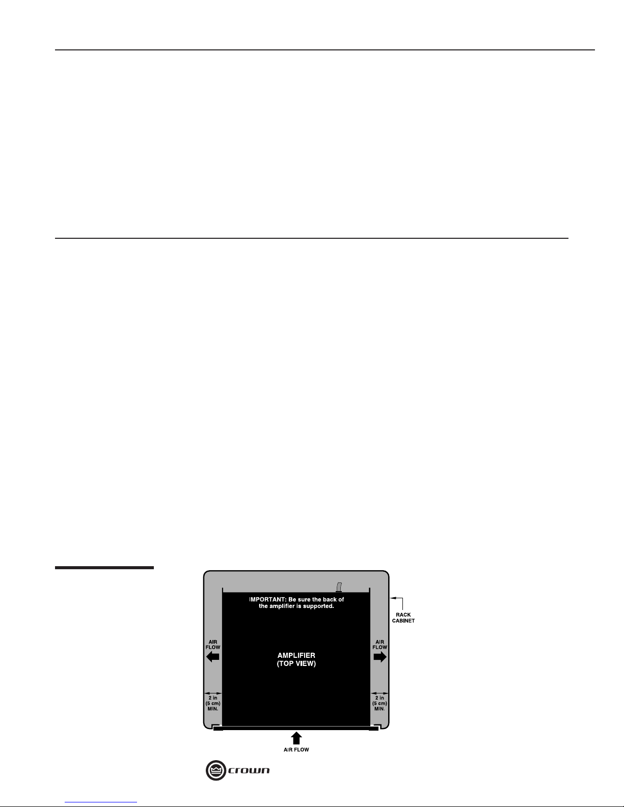
Figure 1.1
Top View of RackMounted Amplifi er with
Side Vents
his chapter provides information to help you get optimum performance
from your Crown amplifi er. It is a collection of techniques that can help
T
you avoid many of the common problems that plague sound systems. For
further study on many of these topics, refer to the recommended publications
listed in the Appendix.
1.1 Rack Cooling
When installing your Crown amp in a rack, you should take steps to make
sure that the temperature of the rack stays in a safe range. Crown amps with
fan-assisted cooling and convection-only cooling may require different tech-
niques for best performance.
When designing your rack
cooling system, you should
consider the requirements
for all mounted components.
1.1.1 Fan-Assisted
Models
If your Crown amplifi er uses
fan-assisted cooling, make
sure that the front vents and/
or fi lters are never blocked,
and that the exhaust fan
(vented out the back or
Amplifi er Application Guide
Page 6
6 Chapter 1: Crown Amplifi ers In-Depth
sides) is not blocked or covered by cables. Also, if your
Crown amp has foam fi lters, they can be cleaned with mild
dish detergent and water when needed.
The side walls of the rack should be at least 2 inches (5
cm) away from the chassis for amps with side venting as
shown in Figure 1.1.
Don’t use vented spacer panels between amps in a rack.
Because of the airfl ow technology we use in our amps,
it is best to stack multiple amplifi ers on top of each other
with no space between.
The amplifi er draws fresh air into the front of the amp
and exhausts it either out the sides and into the rack, or
out the back depending on the model. We want the hot
air that’s in the rack to vent out the sides or back—not
the front. If any of these amplifi ers are spaced apart with
vented panels, some of the preheated air will recycle to
the front of the rack and back into the amplifi er. The result
is loss of thermal headroom. If you choose to place the amplifi ers with space
between them, then use solid panels between them, not vented panels.
You should provide adequate airfl ow within the rack. Additional air fl ow may
be required when driving low impedance loads at consistently high output
levels or for higher power models. Refer to your Crown amplifi er’s Operation
Manual for detailed information on thermal dissipation.
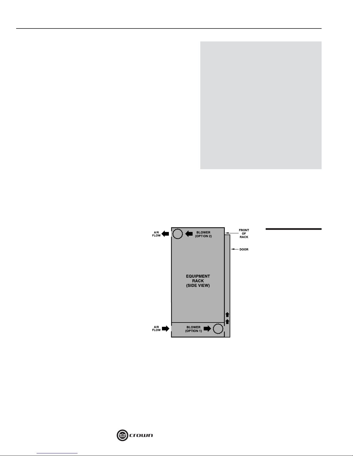
If your rack has a front door that could
block air fl ow to the amplifi er’s air
intakes, you must provide adequate air
fl ow by installing a grille in the door or
by pressurizing the air behind the door.
Wire grilles are recommended over
perforated panels because they tend
to cause less air restriction. A good
choice for pressurizing the air behind a
rack cabinet door is to mount a “squirrel
cage” blower inside the rack (Option 1
in Figure 1.2). At the bottom of the rack,
mount the blower so it blows outside air
into the space between the door and in
front of the amplifi ers, pressurizing the
“chimney” behind the door. This blower should not blow air into or take air out
of the space behind the amplifi ers. For racks without a door, you can evacuate the rack by mounting the blower at the top of the rack so that air inside the
cabinet is drawn out the back (Option 2 in Figure 1.2).
If the air supply is unusually dusty, you might want to pre-fi lter it using commercial furnace fi lters to prevent rapid loading of the unit’s own air fi lter.
Overheating
Because of the wide range of operating
conditions your amplifer might be subjected to in the fi eld, you should consider each installation independently to
ensure the best thermal performance.
If your amp starts to overheat, consider
the following possible causes:
1. Insuffi cient air movement.
2. Overdriving of the input stage
(severely into clip).
3. Very low-impedance loads.
4. High ambient temperatures.
Figure 1.2
Extra Cooling with a
Rack-Mounted Blower
1.1.2 Convection-Only Models
When racking convection-cooled amplifi ers, it is best to leave one rack-space
between amps because this type of amplifi er needs space to radiate the heat.
Amplifi er Application Guide
Page 7
Chapter 1: Crown Amplifi ers In-Depth 7
1.2 System Wiring
The information in this section covers making input and output wiring connections, as well as troubleshooting problems relating to system wiring.
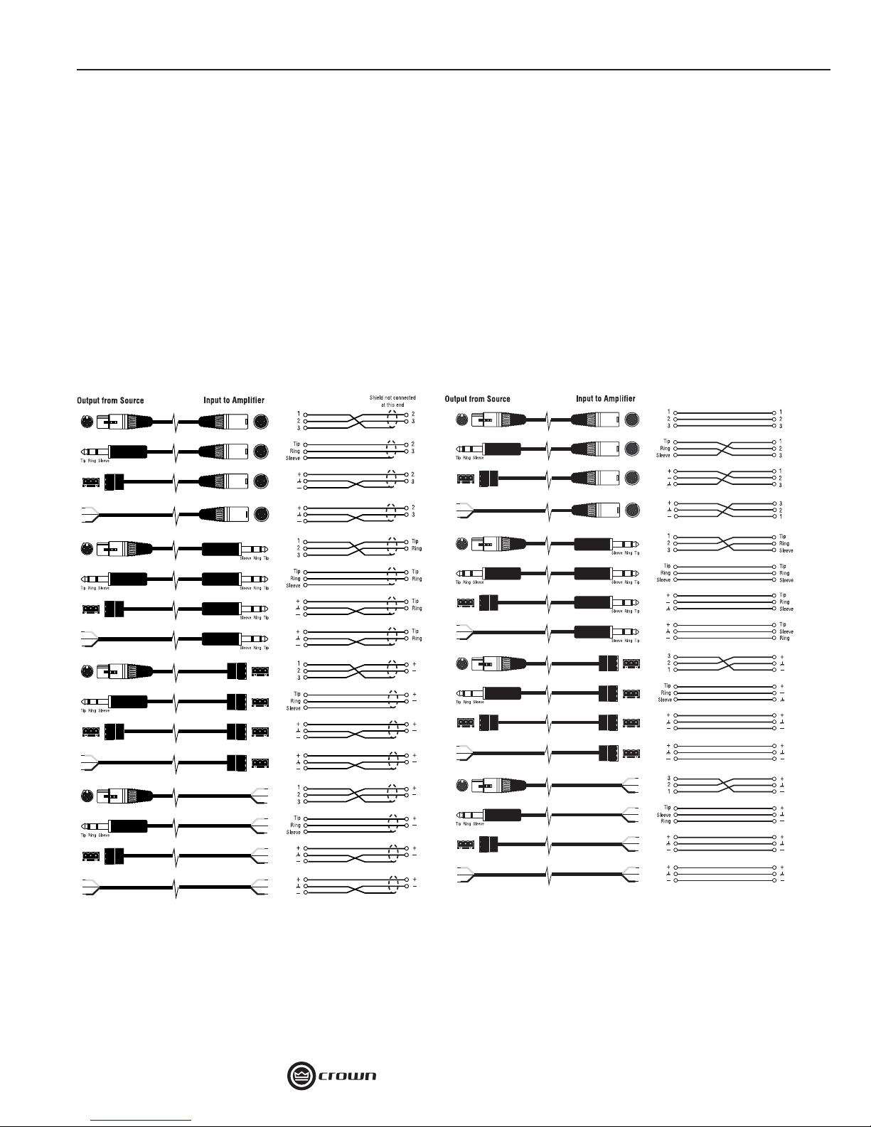
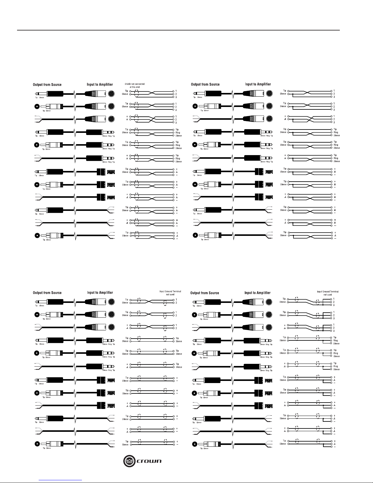
1.2.1 Input Wiring
Input Connector Wiring
Refer to the following diagrams for input cable wiring for commonly-used connector types.
Note: These diagrams follow the AES wiring convention of Pin 2 = hot for XLR
connectors.
Balanced, Grounded Source
For use with components equipped with three-wire
grounded AC line cord or other ground connection.
Balanced, Floating Source
For use with components equipped with two-wire
AC line cord or battery power.
Note: If two or more channels with the same
input ground reference are driven from the
same fl oating source, connect only one shield
to the source chassis
Amplifi er Application Guide
Page 8
8 Chapter 1: Crown Amplifi ers In-Depth
Unbalanced, Grounded Source,
Twin-Lead Shielded Cable
For use with components equipped with three-wire
grounded AC line cord or other ground connection.
Unbalanced, Floating Source,
Twin-Lead Shielded Cable
For use with components equipped with two-wire
AC line cord or battery power.
Unbalanced, Grounded Source, Single-
Conductor Coax or Twisted-Pair Cable
For use with components equipped with three-wire
grounded AC line cord or other ground connection.
Unbalanced, Floating Source, Single-
Conductor Coax or Twisted-Pair Cable
For use with components equipped with two-wire
AC line cord or battery power.
Amplifi er Application Guide
Page 9
Chapter 1: Crown Amplifi ers In-Depth 9
1.2.2 Solving Input
Input Wiring Tips
1. For all input connectivity, use
shielded wire only. Cables with a foil
wrap shield or a high-density braid
are superior. Cables with a stranded
spiral shield, although very fl exible,
will break down over time and cause
noise problems.
2. Try to avoid using unbalanced
lines with professional equipment. If
you have no choice, keep the cables
as short as possible (see “Balanced
vs. Unbalanced” on the next page).
3. To minimize hum and crosstalk,
avoid running low-level input cables,
high-level output wires and AC power
feeds in the same path. Try to run
differing signal-cable paths at 90°
Figure 1.3
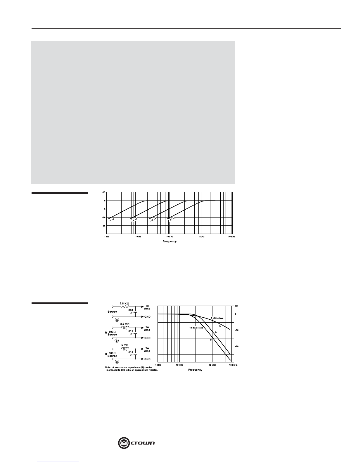
Subsonic Filter Capacitor Values
Figure 1.4
Unbalanced RFI Filters
to one another. If you must use a
common path for all cables, use
a star-quad cable for the low-level
signals.
4. Before changing input connectors or wiring, turn the amplifi er level
controls all the way down (counterclockwise).
5. Before changing output connections, turn the amplifi er level down
and the AC power off to minimize the
chance of short-circuiting the output.
local radio stations, tape recorder bias and digital signal processors (DSP). To prevent high
levels of input RF, install an appropriate low-pass fi lter in series with the input signal.
Some examples of unbalanced wiring for low-pass fi lters are shown in Figure 1.4.
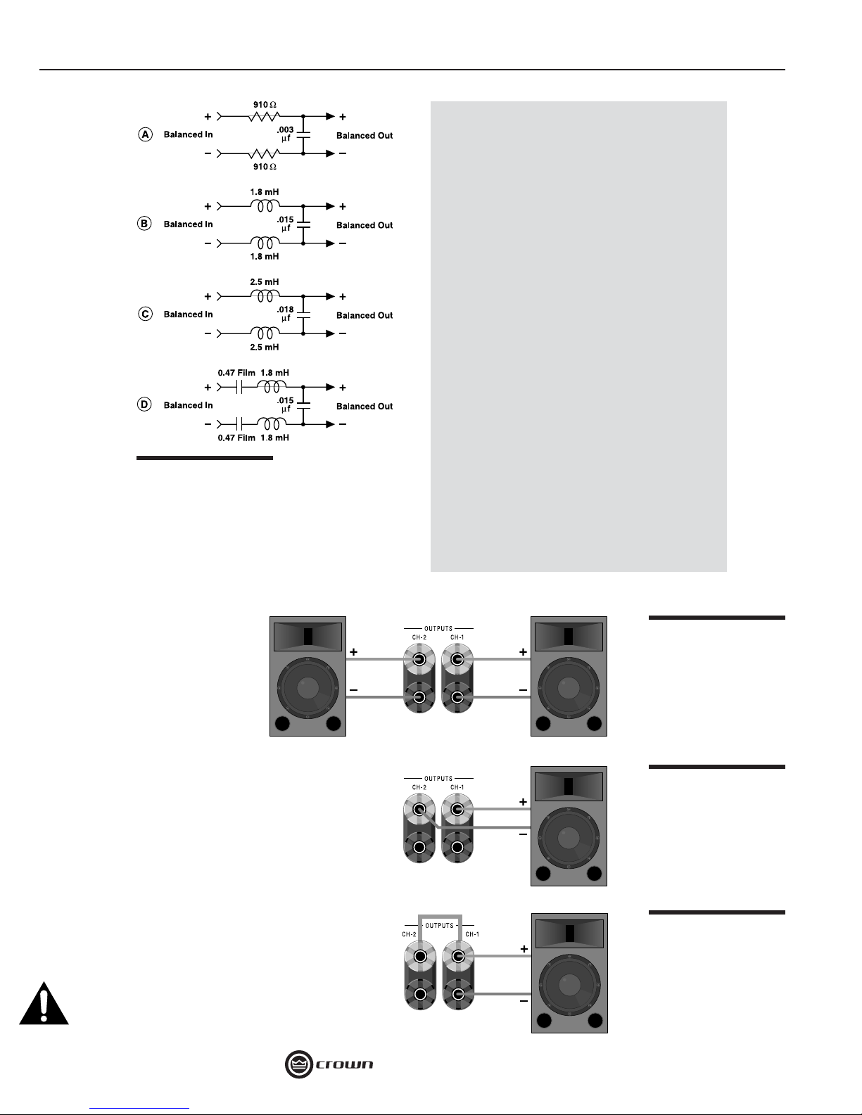
For balanced input wiring use one of the examples in Figure 1.5. Filters A, B and C correspond
to the unbalanced fi lters above. Filter D also incorporates the infrasonic fi lter described previously.
Hum and Buzz
(ungrounded, 2-prong) or grounded (3-prong). Finally, if the source in unbalanced, check the
type of wiring: twin-lead or single coax. Once you have determined the wiring scheme and
cable type, refer to the applicable wiring diagram in Section 1.2.1.
Problems
Infrasonic (Subaudible)
Frequencies
Sometimes large infrasonic (subaudible) frequencies are present in
the input signal. These can damage
loudspeakers by overloading or
overheating them. To attenuate such
frequencies, place a capacitor in
series with the input signal line. The
graph in Figure 1.3 shows some
capacitor values and how they affect
the frequency response. Use only
low-leakage paper, mylar or tantalum
capacitors.
Radio Frequencies (RF)
Another problem to avoid is the
presence of large levels of radio
frequencies or RF in the input signal.
Although high RF levels may not
pose a threat to the amplifi er, they
can burn out tweeters or other loads
that are sensitive to high frequencies. Extremely high RF levels can
also cause your amplifi er to prematurely activate its protection circuitry,
resulting in ineffi cient operation. RF
can be introduced into the signal
chain from many sources such as
If you have noticeable hum or buzz
in your system, you may want to
check your cable connections to
see if the unwanted noise is being
introduced via a ground loop. To
determine the proper wiring, fi rst
check whether the output from
your source is unbalanced or balanced (if you don’t know, refer to
the unit’s back panel or Operation
Manual). Next, determine if the
source’s power cable is fl oating
Amplifi er Application Guide
Page 10
10 Chapter 1: Crown Amplifi ers In-Depth
Balanced vs. Unbalanced
A balanced audio circuit will have both
positive (+) and negative (–) legs of
the circuit that are isolated from the
ground circuit. These balanced legs
exhibit identical impedance characteristics with respect to ground, and may
also carry the audio signal at the same
level, but with opposite polarities. This
results in a line that offers excellent
rejection of unwanted noise.
On the other hand, an unbalanced
circuit usually holds one leg at ground
potential, while the second leg is “hot.”
Unbalanced line is less expensive, but
is much more susceptible to noise, and
is not normally used in professional
applications. For the cleanest signal,
Figure 1.5
Balanced RFI Filters
with less hum and buzz, a balanced
line is always recommended. It is especially helpful if you have a long cable
run (over 10 feet (3 m)), since noise is
easily introduced into long, unbalanced
lines.
1.3 Output Wiring
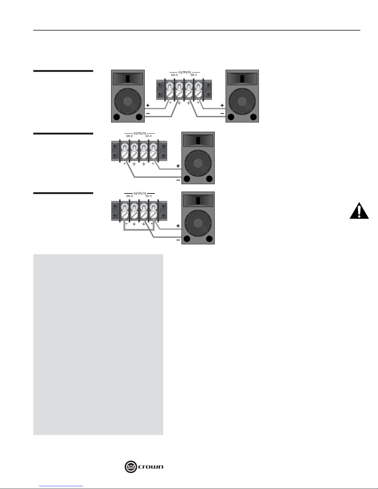
1.3.1 Output Connector Wiring
5-Way Binding Post
If the amplifi er is set for Stereo
(Dual), connect the positive (+)
and negative (–) leads of each
loudspeaker to the appropriate Channel 1 and Channel 2
output connectors as shown in
Figure 1.6.
If the amplifi er is set for Bridge-Mono (if equipped), connect a mono load across the red binding posts of each
channel as shown in Figure 1.7. Do NOT use the black
binding posts when the amp is set for Bridge Output.
Notice that the Channel 1 red binding post is positive
(+) and the Channel 2 red binding post is negative (–).
If amp is set for Parallel-Mono (if equipped), connect
a 14-gauge or larger jumper between the Channel 1
and Channel 2 Positive terminals, then connect a mono
load to the Channel 1 binding posts as shown in Figure
1.8. Do NOT use the Channel 2 binding posts when the
amp is set for Parallel Output. Caution: Never short or
parallel the output channels of an amplifi er to itself
or to any other amplifi er.
Figure 1.6
5-Way Binding Post
Wiring for Stereo
Figure 1.7
5-Way Binding Post
Wiring for Bridge-Mono
Figure 1.8
5-Way Binding Post
Wiring for ParallelMono
Amplifi er Application Guide
Page 11
Chapter 1: Crown Amplifi ers In-Depth 11
Barrier Block
If the amplifi er is set for Stereo (Dual), connect the positive (+) and negative (–) leads
of each loudspeaker to the appropriate Channel 1 and Channel 2 output connectors
Figure 1.9
Barrier Block Wiring for
Stereo
Figure 1.10
Barrier Block Wiring for
Bridge-Mono
Figure 1.11
Barrier Block Wiring for
Parallel-Mono
is set for Bridge Output.
If the amplifi er is set for Parallel-Mono (if
equipped), connect 14-guage or larger
jumper between the Channel 1 and Channel
2 Positive terminals, then connect a mono
load to the Channel 1 positive and negative
terminals as shown in Figure 1.11. Do NOT
use the Channel 2 terminals when the amp
is set for Parallel Output. Caution: Never
short or parallel the output channels of an
amplifi er to itself or to any other amplifi er.
as shown in Figure 1.9.
If the amplifi er is set for
Bridge-Mono (if equipped),
connect a mono load across
the positive terminals of each
channel as shown in Figure
1.10. Do NOT use the negative terminals when the amp
Output Wiring Tips
1. To prevent possible short circuits,
wrap or otherwise insulate exposed
loudspeaker cable or cable connectors.
2. Do not use connectors that might
accidentally tie conductors together
when making or breaking the connection (for example, a standard, 1/4-inch
stereo phone plug).
3. Never use connectors that could
be plugged into AC power sockets.
Accidental AC input will be an electrifying experience for your equipment.
But you will fi nd out real quick if your
speakers are any good at 60 Hz!
4. Avoid using connectors with low current-carrying capacity, such as XLRs.
5. Do not use connectors that have
any tendency to short.
Neutrik® Speakon
To assemble the Neutrik Speakon NL4FC connector, complete
the following steps:
1. Slide the bushing (E) and chuck (D) onto the end of the cable
as shown in Figure 1.12.
Note: Your NL4FC connector kit should contain both a black
and a white chuck. Use the white chuck for cable with a diameter of 0.25 to 0.5 inch (6.35 to 12.7 mm). Use the black chuck
for cable with a diameter of 0.375 to 0.625 inch (9.525 to
15.875 mm).
2. Strip approximately 3/4-inch (20-mm) of casing from the cable
end. Strip approximately 3/8-inch (8-mm) from the end of each
of the conductors down to bare wire (C).
3a. Insert each wire into the top of appropriate slot of the connec-
tor insert (B) as shown in Figure 1.13. Use a (1.5-mm) allen
wrench or fl at blade screwdriver to tighten the side connecting
screws.
®
Amplifi er Application Guide
Page 12

12 Chapter 1: Crown Amplifi ers In-Depth
3b. If the Mode switch is
in the “Stereo” position (for stereo confi guration), connect
the positive (+) and
negative (–) leads
of each wire to the
appropriate Channel 1 and Channel
2 connectors as
shown in Figure
1.14. You may use all 4 poles of the Channel 1 output
connector to feed both speakers, if you wish.
3c. If the Mode switch is in the “Bridge” position (for
mono confi guration), connect the load across the
positive (+) terminals of the connector as shown
in Figure 1.15. For Bridge-Mono Mode, non-inverting output, Ch1+ is the positive (+) and Ch2+ is the
negative (–).
3d. Never short or parallel the output channels of
an amplifi er to itself or any other amplifi er.
4. Slide the connector insert (B) into the connector
housing (A),
making
sure that
the large
notch on
the outer
edge of the
insert lines
up with the
large groove on the inside of the connector housing. The insert should slide
easily through the housing and out the
other side until it extends approximately
3/4-inch (19-mm) from the end of the
housing, as shown in Figure 1.16.
5. Slide the chuck (D) along the cable and
insert into the housing, making sure
that the large notch on the outer edge
of the chuck lines up
with the large groove
on the inside of the
connector housing.
The chuck should
slide easily into the insert/housing combination until only
approximately 3/8-inch (9.5-mm)
of the chuck end extends from
the back end of the connector
as shown in Figure 1.17.
Figure 1.12
Order of Assembly for
the Neutrik Speakon
NL4FC Connector
Figure 1.13
Wiring for the Neutrik
Speakon NL4FC
Connector
Figure 1.14
Stereo Output Wiring
Figure 1.15
Bridge-Mono Output
Wiring
Figure 1.16
Connector Assembly:
Insert into Connector
Housing
Figure 1.17
Connector Assembly:
Chuck into Connector
Housing
Amplifi er Application Guide
Page 13

Chapter 1: Crown Amplifi ers In-Depth 13
Figure 1.18
Connector Assembly:
Bushing onto Connector
Housing Assembly
Figure 1.19
Connecting the
Speakon plug to the
mating connector
Figure 1.20
Series Speaker
Impedances
Figure 1.21
Parallel Speaker
Impedances
6. Slide the bushing along the cable
and screw onto the end of the
connector combination as shown
in Figure 1.18. Note that the
bushing features a special locking construction which will prevent
disassembly of the NL4FC connector once this cap is tightened
into place. Before tightening, you
may want to test the connector in
a live system to make sure it has
been assembled properly.
To connect the Speakon plug into the mating connector on the speaker, line
up the notches between the insert and the mating connector, then insert the
plug and turn one quarter-turn clockwise as shown in Figure 1.19. The thumblock on the housing will snap into the locked position when the connector is
properly seated.
1.3.2 Amplifi er Load Impedance
A major consideration when matching amplifi ers with speakers is the resulting
impedance presented to the amplifi er when speakers are connected to the
output. The impedance of the load, in part, determines how much power the
amplifi er will produce. Also, too low of impedance can cause the amplifi er to
overheat.
Impedance is much like resistance, except impedance
changes with frequency. Impedance and resistance are both
measured in ohms. To understand the effect of impedance
in an electrical circuit, consider
the following analogy: a wire is
much like a water pipe. Electrical current is like the water
fl owing through the pipe. Impedance’s role is that of the valve.
The valve resists or impedes
(hence the terms) the fl ow of
water through the pipe. If the
valve is opened (less impedance), water fl ows freely. As
the valve is turned toward the
closed position (more impedance), the fl ow of water slows.
As the amplifi er drives lower
impedances, it produces more
current, thus more power.
Amplifi er Application Guide
Page 14

14 Chapter 1: Crown Amplifi ers In-Depth
Each speaker has an impedance
secnadepmIlellaraP
rating, typically 4 or 8 ohms. Connecting one 8-ohm speaker to an amplifi er
channel presents an 8-ohm impedance
to the channel.
If two or more speakers are wired to
the same channel, the net impedance
presented to the channel will be either
rekaepS1mhO4mhO8
srekaepS2mhO2mhO4
srekaepS3mhO3.1mhO7.2
srekaepS4mhO1mhO2
srekaepSmhO4srekaepSmhO8
more or less than one of the speakers alone, depending on whether they
were wired in series or in parallel (see Figures 1.20 and 1.21).
When speakers are wired in
series, the net impedance presented to the amp is the sum
of the individual impedances.
When wired in parallel, the net
impedance becomes less than
the impedance of one of the
speakers, as calculated with the
following formula:
Figure 1.22
Parallel Impedance
Chart
Figure 1.23
Wire Size Nomograph.
You can use the table in Figure
1.22 to fi nd the net impedance
for many common speaker
combinations.
Note: for best results, do
not wire speakers of differing impedances (one 4 ohm
and one 8 ohm for example)
together.
If two 8-ohm speakers are wired
in series, they form one 16-ohm
load for the amplifi er, since
impedances add when speakers are wired in series. If, on the
other hand, the same 8-ohm
speakers are wired in parallel, they form one 4-ohm load
for the amplifi er. The 4-ohm
load will cause the amplifi er to
produce much more power than
the 16-ohm load, and much
more waste heat as well.
Amplifi er Application Guide
Page 15

Chapter 1: Crown Amplifi ers In-Depth 15
1.3.3 Determining Appropriate Speaker Wire Gauge
You should choose loudspeaker cables with suffi cient gauge (thickness)
for the length being used. The resistance introduced by inadequate loudspeaker cables will reduce both the output power and the motion control of
the loudspeakers. The latter problem occurs because the damping factor
decreases as the cable resistance increases. This is very important because
the amplifi er’s excellent damping factor can easily be negated by insuffi cient
loudspeaker cables.
Use the nomograph in Figure 1.23 and the procedure that follows to fi nd the
recommended wire gauge (AWG or American Wire Gauge) for your system.
1. Note the load impedance of the loudspeakers connected to each channel
of the amplifi er. Mark this value on the “Load Impedance” (A) line of the
nomograph.
2. Select an acceptable damping factor and mark it on the “Damping Factor”
(B) line. Higher damping factors yield greater motion control over the
loudspeakers, and therefore lower distortion. A common damping factor for
commercial applications is between 50 and 100. Higher damping factors
may be desirable for live sound, but long cable lengths often limit the highest damping factor that can be achieved practically. In recording studios
and home hi-fi , a damping factor of 500 or more is very desirable.
3. Draw a line through the two points with a pencil, and continue until it intersects the “Source Resistance” (C) line.
4. On the “2-Cond. Cable” (D) line, mark the required length of the cable run.
5. Draw a pencil line from the mark on the “Source Resistance” line through
the mark on the “2-Cond. Cable” line, and on to intersect the “Copper Wire”
(E) line.
6. The required wire gauge for the selected wire length and damping factor is
the value on the “Copper Wire” line. Note: Wire size increases as the AWG
gets smaller.
7. If the size of the cable exceeds what you want to use, (1) fi nd a way to use
shorter cables, (2) settle for a lower damping factor, or (3) use more than
one cable for each line. Options 1 and 2 will require the substitution of new
values for cable length or damping factor in the nomograph. For option
3, estimate the effective wire gauge by subtracting 3 from the apparent
wire gauge every time the number of conductors of equal
gauge is doubled. So, if #10 wire is too large, two #13
PIPs for Speaker Protection
Depending on the application, you may
want to use a PIP™ module to protect
your loudspeakers (for PIP-compatible
amps only). When properly confi gured, all
PIP modules with signal-driven compression can provide loudspeaker protection.
For more information on available PIP
modules with signal-driven compression,
contact your Crown dealer or check the
current selection of PIP modules at www.
wires can be substituted, or four #16 wires can be used for
the same effect.
1.3.4 Loudspeaker Protection
Crown amplifi ers generate enormous power. If your loudspeakers don’t have built-in protection from excessive
power, it’s a good idea to protect them. Loudspeakers are
subject to thermal damage from sustained overpowering
and mechanical damage from large transient voltages.
Special fuses can be used to protect your loudspeakers in
both cases.
Amplifi er Application Guide
Page 16

16 Chapter 1: Crown Amplifi ers In-Depth
Two different types of fuses are
required for thermal protection
and voltage protection. Slow-blow
fuses are usually selected to
protect loudspeakers from thermal
damage because they are similar
to loudspeakers in the way they
respond to thermal conditions
over time. In contrast, high-speed
instrument fuses like the Littlefuse
361000 series are used to protect
loudspeakers from large transient
voltages. The nomograph in Figure
1.24 can be used to select the
properly rated fuse for either type
of loudspeaker protection.
There are basically two
approaches that can be taken
when installing fuses for loudspeaker protection. A common
approach is to put a single fuse
in series with the output of each
channel. This makes installation convenient because there is only one fuse protecting the loads on each
output. The main disadvantage of this approach becomes obvious if the fuse
blows because none of the loads will receive any power.
A better approach is to fuse each driver independently. This allows you to
apply the most appropriate protection for the type of driver being used. In
general, low-frequency drivers (woofers) are most susceptible to thermal
damage and high-frequency drivers (tweeters) are usually damaged by large
transient voltages. This means that your loudspeakers will tend to have better
protection when the woofers are protected by slow-blow fuses and high-frequency drivers are protected by high-speed instrument fuses.
Figure 1.24
Loudspeaker Fuse
Nomograph
1.3.5 Solving Output
Problems
High-Frequency Oscillations
Sometimes high-frequency oscillations occur which can cause your amplifi er
to prematurely activate its protection circuitry and result in ineffi cient operation. The effects of this problem are similar to the effects of the RF problem
described in Section 1.2.2. To prevent high-frequency oscillations:
1. Lace together the loudspeaker conductors for each channel; do not lace
together the conductors from different channels. This minimizes the
chance that cables will act like antennas and transmit or receive high frequencies that can cause oscillation.
2. Avoid using shielded loudspeaker cable.
3. Avoid long cable runs where the loudspeaker cables from different amplifi ers share a common cable tray or cable jacket.
Amplifi er Application Guide
Page 17

Chapter 1: Crown Amplifi ers In-Depth 17
Figure 1.25
Inductive Load (Transformer) Network
Figure 1.26
Typical Distributed
Speaker System
4. Never connect the amplifi er’s
input and output grounds together.
5. Never tie the outputs of multiple
amplifi ers together.
6. Keep loudspeaker cables well
separated from input cables.
7. Install a low-pass fi lter on each
input line (similar to the RF fi lters described in Section 1.2.2).
8. Install input wiring according to the instructions in your amplifi er’s Opera-
tion Manual.
Sub-Sonic Currents
Another problem to avoid is the
presence of large sub-sonic currents
when primarily inductive loads are
used. Examples of inductive loads
are 70-volt transformers and electrostatic loudspeakers.
Inductive loads can appear as a
short circuit at low frequencies. This
can cause the amplifi er to produce large low-frequency currents
and activate its protection circuitry.
Always take the precaution of installing a high-pass fi lter in series with
the amplifi er’s input when inductive
loads are used. A 3-pole, 18-dBper-octave fi lter with a –3 dB frequency of 50 Hz is recommended
(depending on the application, an
even higher –3 dB frequency may be
desirable).
Another way to prevent the amplifi er
from prematurely activating its protection systems and to protect inductive
loads from large low-frequency currents is to connect a 590 to 708 µF nonolarized capacitor and 4-ohm, 20-watt resistor in series with the amplifi er’s
output and the positive (+) lead of the transformer. The circuit shown in Figure
1.25 uses components that are available from most electronic supply stores.
1.3.6 Distributed Speaker Systems
Multiple-speaker systems for paging and background music systems are
common in such facilities as schools, restaurants, industrial facilities offi ces
and retail. In these systems, many speakers are distributed throughout the
facility, often across long distances, making them diffi cult and expensive to
implement with traditional, direct low-impedance amplifi ers. A less expensive
and more reliable method is the distributed speaker system.
A distributed speaker system consists of an amplifi er or amplifi er channel
driving one or more speakers with transformers connected to a pair of wires
called a “home run.” The transformers step the line voltage down to a lower
Amplifi er Application Guide
Page 18

18 Chapter 1: Crown Amplifi ers In-Depth
level to drive the speaker, and are connected across the
wires (see Figure 1.26). The combination of transformer
and speaker line presents a much higher impedance to the
amplifi er than would the speaker itself, making it possible to
add many speakers to a single home run.
In distributed speaker systems, as the ratio of voltage to
current become greater, less power is lost on the home run.
This makes it possible to use much smaller gauge wire for
home runs than would otherwise be possible.
What is Constant Voltage?
“Constant-voltage” amplifi ers do not, in fact, supply a constant output voltage. The audio is represented with varying
voltage just as with a low-impedance amplifi er. The term
“constant-voltage” was arrived at for two reasons. First, constant-voltage amplifi ers produce their maximum power when
the output voltage reaches the specifi ed value. For example,
an amplifi er rated at 200 watts, when set to 70V output, will
produce 200 watts when the output voltage reaches 70V.
Second, the output voltage of an amplifi er driving a constant-voltage (distributed) speaker run remains constant
across a wide range of impedances.
Using Low-Impedance
You can use amps without constant-voltage settings on distributed speaker systems if the power output is high enough.
For example, an amplifi er rated for 78
watts output into 8 ohms will directly drive
a 25-volt line. To calculate the necessary
power for driving a specifi c voltage line
use the following formula:
where P equals the necessary power
output,
V equals the voltage of the distributed
speaker system, and R equals the impedance of the amplifi er for the power specifi -
Transformer Saturation
It’s important to know that transformers can easily become “saturated” at low-frequencies. Transformer saturation
occurs when the magnetic fi eld created by the signal content becomes too much for the core of the transformer to
handle. This condition can be dangerous to the amplifi er, and can also cause distortion.
An effective way to prevent step-down transformer saturation is to fi lter the very low-frequency content from the
audio. Your amplifi er may provide high-pass fi lters for this purpose (see your Operation Manual). If not, see Sec-
tion 1.2.2 for fi lter suggestions.
1.4 Multi-way Systems
(with Expansion Modules)
This section shows how multi-way systems can be effectively designed using optional expansion modules that
feature active crossover networks. Example systems are shown for single and multiple amp two-way systems and
three-way systems.
The range of frequencies present in full-range music is wider than most any single speaker component can accurately reproduce. Because of this, most professional speaker systems employ two or more speaker components
to do the job. Crossover networks (or crossovers) are electrical circuits that divide an incoming signal into two
or more separate frequency bands. The separate bands are then routed to speakers designed to reproduce the
range of frequencies they are being fed.
1.4.1 Active vs. Passive Crossover Networks
There are two types of crossovers: active and passive. Passive crossover networks are located in the signal chain
between the amplifi er and speakers. The networks built into speaker cabinets are typically passive. The primary
advantage to passive crossovers is that they use fewer amplifi ed channels. The primary disadvantage is that they
work with amplifi ed or high-voltage signals because of being located after the amplifi er in the signal chain,
causing them to waste much of the power before it gets to the speakers. They also have lower dynamic
range.
Active crossovers are typically located before the amplifi er in the signal chain. They work with lower “line-level”
signals, meaning they waste much less power.
Amplifi er Application Guide
Page 19

Chapter 1: Crown Amplifi ers In-Depth 19
Figure 1.27
Typical Single-Amp,
Stereo, Two-Way
Hookup
Figure 1.28
Typical Two-Amp,
Bridge-Mono, Two-Way
Hookup
Amplifi er Application Guide
Page 20

20 Chapter 1: Crown Amplifi ers In-Depth
Figure 1.29
Typical Three-Amp,
Bridge-Mono,
Three-Way Hookup
When you use an active crossover to split the power drive to the loudspeaker
components, you gain a wide range of advantages, including:
1. Increased gain because the insertion loss of passive crossover networks is
eliminated.
2. Consistent power bandwidth: power bandwidth is changed in multi-way passive systems if transducers change impedance or vaporize (blow up).
3. Levels can be matched
more accurately to the
components.
4. Improved dynamic
range.
Active crossovers for
Crown amps are available
in both PIP and SST modules (see your Operation
Manual for details about
available options for your amplifi er).
Figures 1.27 through 1.29 illustrate typical systems using active crossover
modules.
Figure 1.30
Fault Status External
Circuit Design
Amplifi er Application Guide
Page 21

Chapter 1: Crown Amplifi ers In-Depth 21
Figure 1.31
RJ Jack Wiring and
Pin Assignments
1.5 Fault Monitoring
The Fault (RJ-11) jack, which looks
like a telephone plug, is located
on the back of your amplifi er (if
equipped). It gives you an easy way
to remotely monitor the amplifi er’s fault status. To set up a circuit that will
cause an LED to light whenever a fault status occurs, you can simply use the
suggested circuit shown in Figure 1.30.
When using this circuit, the LED will glow whenever the amplifi er is in one of
four states: a channel’s heatsink has reached its temperature limit, the transformer has reached its temperature limit, the amplifi er has just been turned
on and is in its turn-on-delay mode, or the amplifi er is turned off.
If you choose to design your own circuit to interface this signal to your system,
note that this RJ jack is polarity sensitive. Pin 2 must be grounded, and Pin
5 must be supplied with a positive voltage pull up (positive with respect to
ground). Refer to Figure 1.31 for RJ jack pin assignments. Note: the mating
connector for the RJ-11 jack contains 4 contact pins in a six-slot case, as
shown in Figure 1.31. The maximum signal that can be exposed to the fault
jack is 35 VDC and 10 mA. Best results are obtained with 10 mA LEDs.
Figure 1.32
Optimal System
Headrom.
Available
Headroom
Gain
Amplifier
Headroom
Potential
1.6 Setting
System Gain
Structure
To get the best performance
from your sound system, you
should carefully set up your
system’s gain structure. Gain
structure is a term that refers
Amplifier
to the way the various levels
are set at each stage of your
sound system. Good gain
Outboard
Processing
Mixer
Output
Mixer
Input
structure lets you get your
intended signal out with the
most available headroom, and
the least amount of noise.
This section provides a basic
procedure to use to set up you
system’s gain structure, designed to get you up and running as quickly as
possible. We could go into much more detail on this subject, but that would
be beyond the scope of this manual. If you have questions about system gain
structure, refer to the Appendix for a list of recommended publications for
further reading.
Amplifi er Application Guide
Page 22

22 Chapter 1: Crown Amplifi ers In-Depth
1.6.1 System Levels
When setting system gain, start at the front of the system and work your way toward the
amplifi er. A system with the lowest noise fl oor and maximum overall gain will have most
of its gain early in the signal chain.
Start out by setting your mixer’s individual channels to 0 dB. The individual channels will
vary somewhat from this in the course of setting the mix, but it is a good target position.
Also, if your mixer has a +4/–10 dB switch on the output, set it to the +4 dB position.
Next, if your mixer has input trim controls for the mic channels, set them for the highest
possible gain (but short of clipping) by having someone speak or sing into the mic while
monitoring the mixer’s metering.
Set up your mix for the balance of signals as you want them, keeping the input faders
somewhere around the 0 dB point. If necessary, turn down the trim on a channel if
you’re not able to keep the fader near the 0 dB point.
After the mix is set, adjust the master levels on the mixer to 0 dB. Any signal processing
equipment should generally be set to 0 dB as well, with some exceptions (refer to each
component’s documentation for details).
1.6.2 Amplifi er Level
Before you can know how to set your amps level controls, you need to understand how
they work. Amplifi er level controls are typically not “gain” controls. They do not control
the amount of gain the amplifi er produces. You may be tempted to immediately turn your
amps level control all the way up (after all, you do want all the Crown power you can get,
don’t you?). While that approach could work sometimes, usually it will yield more noise
and less overall system gain than would otherwise be possible.
Power amplifi ers are designed to produce a set amount of gain. The function of the level
control knob typically is to adjust the signal level coming into the amplifi er’s input stage.
Where to set the level controls on the amp depends on the system and how much gain
you have available prior to the amplifi er. With the level controls turned down the amplifi er can still reach full rated output power, it just takes more drive level from your mixer to
achieve it.
First, check to make sure your mixer or console is being operated at optimum signal-to
-noise, without clipping the output. Then—with your amplifi er’s input sensitivity set to
the 26 dB position (if equipped)—turn up your amp’s level controls until you achieve the
desired level (loudness). If you turn the level controls all the way up, and it’s still not loud
enough, turn the amplifi er level controls all the way down (counter-clockwise). Then,
change the sensitivity switch to the 1.4V position (if equipped). This will increase the
gain of the amplifi er. Now carefully turn the amplifi er level controls up (clockwise) to the
desired level (loudness). If its still not loud enough, and your amplifi er has a 0.775V sensitivity setting, turn the amplifi er level controls all the way down (counter-clockwise), then
change the sensitivity switch to the 0.775V position. Take care when you are adjusting
the level controls at this input sensitivity setting. Increasing the input sensitivity of the
amplifi er may cause the input stage of the amp to overload, so be prepared to back
down the output of the mixer by 1 or 2 dB if you notice the amplifi er’s warning indicators
beginning to fl ash.
Note: depending upon your model of Crown amplifi er, sensitivity settings are internal
and NOT user-selectable. Internal sensitivity settings may only be adjusted by qualifi ed
service personnel. Refer to your amplifi er’s Operation Manual for specifi cs about sensitivity settings on your amplifi er.
Amplifi er Application Guide
Page 23

Chapter 2: Troubleshooting 23
Chapter 2
Troubleshooting
In This Chapter
• Troubleshooting Flowcharts
Figure 2.1
Flowchart Key
his section provides fl owcharts to assist you in troubleshooting problems
T
with your amplifi er. In some situations the problem may not be with the
amplifi er, but rather may be caused by a system condition.
The fl owcharts do not cover every possible scenario you may encounter.
Figure 2.1 provides a key to help you interpret the fl owcharts.
Start and
Finish Points
Question
Comment
Action Step
Amplifi er Application Guide
Page 24

24 Chapter 2: Troubleshooting
2.1 No Power
No Powe r
Is amp plugged
in to the AC
source?
Yes
Is the Power
(Enable)
switch on?
Yes
Is the Power
(Enable)
indicator lit?
Figure 2.2
No Power
No
No
Plug amp in to the
AC source.
Turn the Power
(Enable) switch on.
No
Is AC source
supplying power
to outlet?
No
Restore AC power
to outlet.
Yes
Is a n
IQ System
controlling
amp?
No
Yes
Verify power to
amp is turned on
in IQ System.
Yes
Does amp have
a fuse or circuit
breaker?
Fuse
Is f u se
internal or
external?
Inte rnal Exte rnal
Internal Fuses
NOT
user-replaceable.
Circuit
Brea ker
Replace fuse
with new fuse
of identical
rating.
Reset circuit
breaker.
Did it trip
again?
Yes
Amp o.k. to
No
operate.
Refer amp to
service center.
Amplifi er Application Guide
Page 25

Chapter 2: Troubleshooting 25
Figure 2.3
No Sound
indicator on?
Are the le vel
No Sound
Is Powe r o r
Enable
Yes
Are signal
indicators
blinking?
Yes
controls
turned up?
Yes
2.2 No Sound
Check AC Power to
No
amp. See "No Power"
Check signal source
No
for adequate output.
Turn up level controls
No
until you hear output.
flowchart.
Does amp have
IQ PIP model
installed?
No
Are speakers'
protection
systems tripped,
or speakers
damaged?
Yes
Yes
Check settings on
IQ PIP module.
Repair or reset
speaker.
Are speakers
connected?
Yes
Is there a
short-circuit on
the speaker
line?
No
Connect Speakers
No
Yes
to Amp.
Remove the
short-circuit.
Fault or TLC
Is i ndi cat o r
on?
No
Refer amp to
service center .
Yes
No
Does amp have
Fault, TLC or
ODEP
indicators?
ODEP
Is i ndi cat o r
off?
No
Neither Fault,
TLC or ODEP
Yes
Amp overheated or in
other standby condition.
See "Amp Overheating"
flowchart and/or refer to
Operation Manual.
Amplifi er Application Guide
Page 26

26 Chapter 2: Troubleshooting
2.3 Bad Sound
Figure 2.4
Bad Sound
Possible Ca uses
Bad Sound
Is source signal
clean and
undistorted?
Yes
Check levels and/or
No
indicators at sour ce
level for clipping .
Are OD EP
indicators (if
equipped) dim or
off?
No
Are the IOC or
Clip indicators (if
equipped)
flashing or on?
Yes
Yes
Amp overheating.
See "Amp
Overheating"
flowchart.
Check amp
for clipping.
Is there a
Hum or Buzz
sound?
No
Yes
2.4 Amp
Overheating
See "Hum and
Buzz" in
Section 1.2.2.
Amp
Ove rhe ating
Are the filters
(if equipped)
clogged?
No
No
Are input and
output
connections o.k.?
Yes
Refer amp to
service center.
Yes
No
output connections.
Clean or replace
filters.
"Setting System
Gain Structure in
Secure input and
System Ga in
Structure. See
Section 1.6.
Amp not adequately
cooled. See "Amp
Overheating"
flowchart.
Figure 2.5
Amp Overheating
Is t h e a mp
getting enough
cool air?
Yes
Is t h e a mp
operating within
its rated
impedance?
No
Refer amp to
service center .
See "Rack Cooling" in
No
Yes
Section 1.1, and info
on amp cooling in
Operation Manual.
Lower impedances cause
amps to dissipate more
heat. See "Amplifier Load
Impedance" in Section 1.3.2.
Amplifi er Application Guide
Page 27

Chapter 3: Glossary of Terms 27
Chapter 3
Glossary of Terms
In This Chapter
• Glossary of Terms
his section provides a handy glossary of terms used in the discussion of profes-
T
sional audio amplifi ers. Some terms are unique to Crown amplifi ers. Most of the
terms provided do not directly relate to amplifi ers, but as amplifi ers are but one piece
of a larger audio system, are often used when discussing amp usage.
English
Amperage
A measure of electrical current fl ow, also called “amps” for
short. It literally equates to the number of electrons in a
conductor fl owing past a certain point in a given amount of
time. Ohms law defi nes current (I) as voltage (V) divided by
resistance (R) with the following expression: I=V/R.
Amplifi er (Amp)
A device that increases signal. Many types of amplifi ers are
used in audio systems. Amplifi ers typically increase voltage,
current, or both.
Amplifi er Class
Audio power amplifi ers are classifi ed primarily by the design
of the output stage. Classifi cation is based on the amount
of time the output devices are made to operate during each
cycle of swing. Amplifi ers are also defi ned in terms of output
bias current (the amount of current fl owing in the output
devices with no signal present). Common amplifi er classes
used in professional audio amplifi ers include AB, AB+B, D, G
and H.
Attenuation
A decrease in the level of a signal is referred to as attenuation. In some cases this is unintentional, as in the attenuation
caused by using wire for signal transmission. Attenuators
(circuits which attenuate a signal) may also be used to lower
the level of a signal in an audio system to prevent overload
and distortion.
Balanced Line
A cable with two conductors surrounded by a shield, in which
each conductor is at equal impedance to ground. With respect
to ground, the conductors are at equal potential but opposite
polarity; the signal fl ows through both conductors.
Band-Pass Filter
In a crossover, a fi lter that passes a band or range of frequencies but sharply attenuates or rejects frequencies outside the
band.
Barrier Block/Barrier Strip
A series of connections, usually screw terminals, arranged
in a line to permanently connect multiple audio lines to such
devices as recording equipment, mixers, or outboard gear.
Also called terminal strip.
®
BCA
BCA (Balanced Current Amplifi er) is Crown’s patented PWM
(Pulse-Width Modulation) amplifi er output stage topology.
Also referred to as “class-I,” Crown’s BCA “switching” technology provides for high output, exceptional reliability and nearly
twice the effi ciency of typical amplifi er designs. To learn more
about BCA, download and read the BCA white paper at www.
crownaudio.com.
Binding Post (5-Way, Banana)
A type of electrical terminal, a binding post is most commonly
found as the output connector on a power amplifi er, or as the
connectors on a speaker cabinet. A binding post can accept
banana plugs, spade lugs, bare wire and others. Generally,
binding posts are color coded, with the black connection
going to ground, and the red connecting to hot.
Bridge-Mono
An operating mode of an amplifi er that allows a single input
to feed two combined output channels in order to provide a
single output with twice the voltage of an individual channel in
Stereo or Dual mode.
Amplifi er Application Guide
Page 28

28 Chapter 3: Glossary of Terms
Bus
In audio terms, a Bus is a point in a circuit where many signals are brought together. For example: Most electronic items
have a Ground Bus where all of a device’s individual ground
paths are tied together. In mixers, we have Mix Busses, where
multiple channels’ signals are brought (or blended) together,
and Aux Busses, where feeds from channels are brought
together to be routed to an external processor or monitor
send, etc. In general, the more busses a mixer has, the more
fl exible the routing capabilities of that mixer will be.
Capacitor
An electronic component that stores an electric charge. It is
formed of two conductive plates separated by an insulator
called a dielectric. A capacitor passes AC but blocks DC.
Channel Separation
Relates to crosstalk, or bleed of audio signals from one channel to another. The amount of channel separation is inversely
related to the item’s crosstalk spec; i.e. a low crosstalk spec
indicates high channel separation.
Circuit Breaker
A resettable device intended to provide protection to electrical
circuits. It opens when current fl ows though it that exceeds its
current rating.
Clipping
A specifi c type of distortion. If a signal is passed through an
electronic device which cannot accommodate its maximum
voltage or current requirements, the waveform of the signal
is sometimes said to be clipped, because it looks on a scope
like its peaks have been clipped off by a pair of scissors. A
clipped waveform contains a great deal of harmonic distortion
and often sounds very rough and harsh. Clipping is what typically happens when an audio amplifi er output is overloaded
or its input over driven.
A Clip Indicator on an amplifi er indicates the presence of clipping distortion.
Compressor
A compressor is a device that reduces the dynamic range of
an audio signal. First a threshold is established. When the
audio signal is louder than this threshold, its gain is reduced.
Crossover Network (Crossover)
An electronic network that divides an incoming signal into two
or more frequency bands.
Crossover Slope
High- and low-pass fi lters used for speakers do not cut off frequencies like brick walls. The roll-off occurs over a number of
octaves. Common fi lter slopes for speakers are 1st- through
4th-order corresponding to 6 dB per octave to 24 dB per
octave. For example, a 1st-order, 6 dB per octave high-pass
fi lter at 100 Hz will pass 6 dB less energy at 50 Hz, and 12
dB less energy at 25 Hz. Within the common 1st through 4th
fi lters there is an endless variety of crossover types including
Butterworth, Linkwitz-Riley, Bessel, Chebychev and others.
Crosstalk
Signal bleeding or leaking from one channel of a multi-channel device to another.
Current
Literally, the rate of electron fl ow in an electrical circuit. Cur-
rent is measured in Amperes (or Amps), abbreviated I. Ohms
law defi nes current as voltage (V) divided by resistance (R)
with the following expression: I=V/R.
Damping Factor
Though technically more complex than this, damping factor
is usually thought of as an indicator of how tight an amplifi er
will sound when powering bass speakers. A speaker’s driving
motor is a coil of wire (called a voice coil) mounted within a
magnetic fi eld. As this coil of wire moves within the fi eld a
voltage will be induced in the voice coil. If resonant motions of
the speaker are not suffi ciently short-circuited by the amplifi er, the speaker output can have an over accentuated or
“boomy” bass sound.
From a technical measurement stand point, damping factor
is the ratio of the rated speaker impedance to the amplifi er’s
output impedance. Low output impedance is the consequence
of the amplifi er having substantial negative voltage feedback
taken from its output terminals. Properly designed negative
feed back not only corrects for output voltage errors induced
by the speaker but also produces other benefi ts, including low
distortion, low noise (hiss), and fl at frequency response.
DC Output Offset
The presence of DC (Direct Current) at the output of the
amplifi er. Any more than approximately 10 millivolts (positive
or negative) could be an indication of a problem within the
amplifi er.
Decibel
A decibel, a tenth of a bel, is used as an expression of the
ratio between signal levels.
One decibel is commonly taken as the smallest volume
change the human ear can reasonably detect. Doubling the
POWER of an amplifi er results in a 3 dB increase, which is
a “noticeable” volume increase. Doubling the VOLUME of a
sound is a 10 dB increase.
dBV is decibels relative to 1 volt. dBu is decibels relative to
0.775 volt. dBm is decibels relative to 1 milliwatt.
Distributed Speaker System (Constant Voltage System)
A type of speaker system where transformers typically are
used at the output of an amplifi er and at each speaker in
order to provide a constant voltage (most commonly 70V or
100V) that can be tapped by multiple speakers. These lines
can be run great distances with less loss and can have many
more speakers on them than typical high current speaker
lines. These types of systems are generally employed in
situations where an amplifi ed signal must be distributed over
vast areas without a need for very high sound level in any
one area. This type of P.A. system is typically used in schools,
churches, business offi ces, and other commercial facilities.
Dynamic Range
The dynamic range of a sound is the ratio of the strongest or
loudest part, to the weakest or softest part; it is measured in
dB. An orchestra may have a dynamic range of 90 dB, meaning the softest passages have 90 dB less energy than the
loudest ones.
EMI
EMI (Electro Magnetic Interference) refers to interference in
audio equipment produced by the equipment or cabling picking up stray electromagnetic fi elds. This interference usually
Amplifi er Application Guide
Page 29

Chapter 3: Glossary of Terms 29
manifests itself as some type of hum, static, or buzz. Such
electromagnetic fi elds are produced by fl uorescent lights,
power lines, computers, automobile ignition systems, television monitors, solid state lighting dimmers, AM and FM radio
transmitters, and TV transmitters. Methods for controlling
EMI include shielding of audio wiring and devices, grounding, elimination of ground loops, balancing of audio circuits,
twisting of wires in balanced transmission lines, and isolation
transformers among others. Completely eliminating EMI in
a system ranges from easy to nearly impossible depending
upon the equipment and the environment in question.
Equalization (EQ)
The adjustment of frequency response to alter tonal balance
or to attenuate unwanted frequencies.
Fader
Another name for variable attenuator, volume control, or
potentiometer. A fader works like a standard potentiometer,
only instead of rotating, it slides along a straight path. Faders
are commonly found on mixers.
Fault
A term used to describe any condition that could cause an
amplifi er or amplifi er channel to place itself in “standby” or
offl ine mode for protection.
An indicator on some Crown amplifi ers that blinks to show
that the amplifi er is in “Fault,” or a standby or offl ine condition.
Frequency
In audio, the number of cycles per second of a sound wave
of an audio signal, measured in hertz (Hz). A low frequency
(for example 100 Hz) has a low pitch; a high frequency (for
example 10,000 Hz) has a high pitch.
Frequency Range/Frequency Response
Frequency Range is the actual span of frequencies that a
device can reproduce, for example from 5 Hz to 22 kHz.
Frequency Response is the Frequency Range versus Amplitude. In other words, at 20 Hz, a certain input signal level may
produce 100 dB of output. At 1 kHz, that same input level may
produce 102 dB of output. At 10 kHz, 95 dB, and so on.
Fuse
A device intended to provide protection to electrical circuits.
It burns open when current fl ows though it that exceeds its
current rating.
Gain
How much an electronic circuit amplifi es a signal is called
its “gain.” In most specs or references gain is expressed as
a decibel value. Occasionally gain may be expressed as a
straight numeric ratio (a voltage gain of 4 or a power gain of
2).
Ground
In electricity, a large conducting body, such as the earth or an
electric circuit connected to the earth, used as a reference
zero of electrical potential.
A conducting object, such as a wire, that is connected to a
position of zero potential for the purpose of “grounding” an
electronic device.
A power ground or safety ground is a connection to the power
company’s earth ground through the power outlet. In the
power ground of an electronic component with a grounded
plug, the ground connection on the plug is wired to the
component’s chassis. This wire conducts electricity to power
ground if the chassis becomes electrically “hot,” preventing
electrical shock.
In audio, ground usually refers to either the electrical ground
mentioned above, or to an audio shield. An audio shield is
not always a ground and should never be used as a safety
ground. That they are often at ground potential is a function
of how they may be connected to other equipment. Many
audio devices have the ability to disconnect their signal paths
entirely from electrical ground as a way to prevent hum or
ground loop problems.
Verb - to “ground” something means connecting it electrically
to ground.
Ground Lift
Ground lift is a switch found on many pieces of audio equipment which disconnects audio signal ground from earth or
chassis ground.
Using ground lift switches is considered to be far safer than
the “3-to-2 prong AC adapter” solution.
Ground Loop
A loop or circuit formed from ground leads.
The loop formed when unbalanced components are connected together via two or more ground paths–typically the
connecting-cable shield and the power ground. Ground loops
cause hum and should be avoided.
Grounded Bridge™
Grounded Bridge is the name of an amplifi er output topology
developed by Crown in the 1980’s, and used in many Crown
amplifi er models. The patented Grounded Bridge design
consists of four quadrants and an ungrounded power supply.
While two of the output quadrants operate much like a conventional (AB+B push-pull) linear amplifi er, the other two work
in a push-pull confi guration to control ground reference for the
supply rails.
To learn more about Grounded Bridge, download and read
the Grounded Bridge white paper at www.crownaudio.com.
Headroom
The difference between the normal operating level of a
device, and the maximum level that device can pass without
distortion. In general the more headroom the better.
Hertz
The inverse of the time required for one complete cycle of
a wave. Thus, a 10 Hz sine wave takes 1/10 of a second to
complete a full cycle. In practice, it is the frequency or number
of wave cycles occurring per second. In the audio range this
equates to what we perceive as pitch. Abbreviated Hz.
High-Pass Filter
A fi lter that passes frequencies above a certain frequency
and attenuates frequencies below that same frequency. It can
also be called a low-cut fi lter.
Hum
An unwanted low-pitched tone (60 Hz and its harmonics)
heard in the speakers. The sound of interference generated
in audio circuits and cables by AC power wiring. Hum pickup
is caused by such things as faulty grounding, poor shielding,
and ground loops.
English
Amplifi er Application Guide
Page 30

30 Chapter 3: Glossary of Terms
I
Load/ILimit Indicator
An indicator of some Crown amplifi ers that shows current fl ow
to the loudspeakers (“current load”) and the maximum current available from the amplifi er (“current limit”). Typically, the
indicator will glow one color to indicate that current is fl owing
to the loads connected to the amplifi er output channel, and
change to another color to show that the amplifi er channel is
delivering its maximum output current.
Impedance
Impedance refers to the resistance of a circuit or device to AC
(alternating current). Most modern electronic audio devices
have extremely high input impedances so they can be driven
by very low power outputs. Impedance is measured in ohms.
The symbol Ω (omega) is often used to represent resistance.
Input
The connection going into an audio device. In a mixer or
mixing-console, a connector for a microphone, line-level
device, or other signal source.
Intermodulation Distortion (IMD)
Nonlinear distortion that occurs when different frequencies
pass through an amplifi er at the same time and interact to
create combinations of tones unrelated to the original sounds.
IMD specifi cations are usually expressed as a percentage of
the amplifi er’s output, and the lower the percentage the better.
®
IOC
The IOC (Input Output Comparator) circuit compares the
output signal of the amplifi er with the input signal. If there is
any difference other than gain, then it is considered distortion and the indicator comes on. The LED indicator will come
on whenever there is distortion of 0.05% or more. This is a
dynamic Proof of Performance of the amplifi ers functionality.
Anytime you experience distortion in your system you can
view the IOC indicators. If they are not lit then you know that
the amplifi er is not at fault. If the IOC indicators are on, then
the amplifi er is in distortion.
To learn more about IOC, download and read the IOC white
paper at www.crownaudio.com.
Limiter
A limiter is a dynamics processor very similar to a compressor. In fact, many compressors are capable of acting as limiters when set up properly. The primary difference is the ratio
used in reducing gain. In a limiter, this ratio is set up to be as
close to infi nity:1 as possible (no matter how much the input
signal changes, the output level should remain pretty much
constant). The idea is that a limiter establishes a maximum
gain setting, and prevents signals from getting any louder
than that setting.
Line Level
Generally defi ned in the audio industry as +4 dBu (1.23 volts)
for balanced “pro” gear, and .316 volts (–10 dBV) for unbalanced “semi-pro” gear. “ It is best to match the levels of the
gear you are using so that –10 dBV equipment isn’t directly
feeding +4 dBu equipment, and vice versa. If you use gear of
both levels, there are various level matching devices on the
market to properly interface the items.
Linear Power Supply
A power supply that converts AC mains power for use by the
amplifi er by means of a conventional transformer operating at
the same frequency as that of the AC mains supply (usually
50 to 60 Hz).
Loudspeaker
A transducer that converts electrical energy (the signal) into
acoustical energy (sound waves).
Loudspeaker Offset Integration
A feature on some Crown amplifi ers that helps reduce output
clipping and off-center woofer cone movement caused by the
presence of large infrasonic (subaudible) frequencies. The
circuit adds a third order high-pass Butterworth fi lter with a –3
dB frequency of 35 Hz.
Low-Pass Filter
A fi lter that passes frequencies below a certain frequency and
attenuates frequencies above that same frequency. It can
also be called a high-cut fi lter.
Mic Level
The level (or voltage) of signal generated by a microphone.
Typically around 2 millivolts.
Negative Feedback
If some of the output of an amplifi er is made to be out of
phase, and mixed back with the amp’s input signal, it will
partially cancel the input, reducing the gain of the amplifi er;
this is called negative feedback. But, because it contains and
therefore cancels any distortion introduced by the amplifi er,
negative feedback also has the effect of improving the linearity of the amplifi er. Negative feedback can also lower output
impedance, increasing damping factor, and can sometimes
be made to fl atten frequency response. The key to negative
feedback amplifi ers is careful design. Too much phase shift
and the amp will be unstable, and too much feedback will
cause Transient Intermodulation Distortion.
Noise
Unwanted sound, such as hiss from electronics or tape. An
audio signal with an irregular, non-periodic waveform.
Noise Floor
The noise fl oor of a device or system is the amount of noise
generated by the device itself with no signal present, it is
measured in decibels. All electronic devices will generate a
certain amount of noise, even a piece of wire! Minimizing the
noise fl oor leads to expanded dynamic range, and cleaner
recordings or sound production.
®
ODEP
ODEP (Output Device Emulator Protection) is an analog
computer simulation of the output device thermal impedance. In layman’s terms ODEP stores how much power the
amplifi er delivers to its load and its heatsink temperature. If
the protection circuit determines that the output stage is being
overstressed or cannot dissipate any further heat, then output
stage drive is limited.
To learn more about ODEP, download and read the ODEP
white paper at www.crownaudio.com.
Output
A connector in an audio device from which the signal comes
and then feeds successive devices.
Overload
The distortion that occurs when an applied signal exceeds a
system’s maximum input level.
Parallel-Mono
As implemented in Crown amplifi ers, an operating mode of
Amplifi er Application Guide
Page 31

Chapter 3: Glossary of Terms 31
the amplifi er that allows a single input to feed two combined
output channels in order to provide a single output with twice
the current of an individual channel in Stereo or Dual mode.
Peak
On a graph of a sound wave or signal, the highest point in the
waveform. The point of greatest voltage or sound pressure in
a cycle.
Phase Response
The measure of displacement of a time-varying waveform
between an amplifi er’s input and output. Expressed in
degrees.
Phone Plug
A cylindrical plug, usually 1/4-inch (6.35-mm) in diameter. An
unbalanced phone plug typically has a tip for the hot signal
and a sleeve for the shield or ground. A balanced phone
plug typically has a tip for the hot signal, a ring for the return
signal, and a sleeve for the shield or ground.
Phono Plug
A coaxial plug with a central pin for the hot signal and a ring
of pressure-fi t tabs for the shield or ground. Phono plugs are
used for unbalanced signals only. Also called an RCA plug or
pin jack.
PIP™
PIP stands for Programmable Input Processor. These are
optional modules that can be plugged into any PIP-compatible amplifi er. There are a variety of PIP modules with varying
functions. Since fi rst introducing PIP-compatible amplifi ers
and PIP modules, Crown has updated the PIP standard. This
affects which PIP-compatible amplifi ers can host certain PIP
modules. Following are descriptions of the two PIP standards.
Crown’s original PIP module was designed with a 22-pin edge
connector, which mated with a slide-in card rail on PIP-compatible amplifi ers.
PIP2™
The PIP2 standard, announced in 1998, upgraded the PIP
feature set and requires both 18- and 20-pin ribbon cables
which mate with a PIP2-compatible amplifi er using standard
ribbon connectors.
Polarity
In electronics, the relationship between two points that have
opposite electric potentials (one is positive, the other negative) irrespective of time. This is not the same as being 180
degrees out of phase (although the results can be similar).
Phase implies a relationship with time, polarity does not.
Potentiometer (Pot)
An electronic component that is used to provide variable
control over an electronic circuit. It is usually controlled by a
rotary knob which can be turned by hand; a volume control is
a good example of this.
Power
Literally, the rate at which energy is consumed. Power is
expressed in Watts, abbreviated W. In electrical circuits,
power is determined by the amount of resistance (R) times
the amount of current squared with the following expression:
2
P=I
R.
Power Amplifi er
In audio, an electronic device that amplifi es or increases the
power level fed into it to a level suffi cient to drive a loudspeaker.
Radio Frequency Interference (RFI)
Radio-frequency electromagnetic waves induced in audio
cables or equipment, causing various noises in the audio
signal.
®
Removable Terminal Block (Buchanan
, Phoenix)
A series of screw terminal connections arranged in a line on a
removable connector. Often found in three-terminal and fourterminal versions in audio applications. Often referred to by
their brand name, such as “Buchanan
®
” and “Phoenix.”
Resistance
The opposition of a circuit to a fl ow of direct current. Resistance is measured in ohms. The symbol Ω (omega) is often
used to represent resistance. Ohms law defi nes resistance as
voltage (V) divided by current (I) with the following expression:
R=V/I.
Resistor
An electronic component that opposes current fl ow.
Sensitivity
In audio terms, sensitivity is the minimum amount of input
signal required to drive a device to its rated output level.
Normally, this specifi cation is associated with amplifi ers and
microphones, but FM tuners, phono cartridges, and most
other types of gear have a sensitivity rating as well.
Shield
In electronic terms, a shield is a conductive enclosure,
protecting its contents from magnetic and electrostatic fi elds.
Since audio conductors and circuits tend to be extremely
sensitive to such fi elds, shields are very important. In cabling,
shields often consist of braided copper strands wrapped
around the signal conductors. The amount of coverage the
shield provides is directly related to the noise and hum performance of the cable. Some cables offer a shield consisting
of a thin wrap of metallic sheeting, which can offer complete
coverage of the encased signal conductors.
Signal-To-Noise Ratio (S/N)
The ratio in decibels between signal voltage and noise voltage. An audio component with a high S/N has little background noise accompanying the signal; a component with a
low S/N is noisy.
Sine Wave
A wave following the equation y = sin x, where x is degrees
and y is voltage or sound pressure level. The waveform of
a single frequency. The waveform of a pure tone without
harmonics.
Single-Ended
An unbalanced line (see Unbalanced).
Slew Rate
Slew rate is the ability of a piece of audio equipment to
reproduce fast changes in amplitude. Measured in volts per
microsecond, this spec is most commonly associated with
amplifi ers, but in fact applies to most types of gear. Since high
frequencies change in amplitude the fastest, this is where
slew rate is most critical. An amp with a higher slew rate will
sound “tighter” and more dynamic to our ears. Slew rates in
amplifi ers are often limited to useful levels to provide protection to the amplifi er from Radio-Frequency Interference (RFI).
English
Amplifi er Application Guide
Page 32

32 Chapter 3: Glossary of Terms
Sound Pressure Level (SPL)
The acoustic volume or perceived loudness of sound, measured in
decibels. SPL is a function of a signal’s amplitude.
Speakon®
A type (and brand) of multi-pin connector developed by Neutrik®
which is now commonly found on speakers and amplifi ers intended
to be used in high power mobile applications. They have become
popular because they offer a very high quality reliable connection,
can handle extremely high power, are very durable, and are relatively
low in cost compared to other similar connectors. Standard Speakon
connectors come in four or eight conductor versions (though other
confi gurations are available). The Speakon 8 has the same footprint
as the EP8 connector and the Speakon 4 has the same footprint as
XLR “D” type connectors.
Stereo (Dual)
An operating mode of an amplifi er that allows channels of the
amplifi er to function independently.
Switching Power Supply
A power supply that fi rst converts AC mains power to a much higher
frequency by means of a switching circuit before making the power
available for use within the amplifi er. The primary benefi ts of a switching power supply are decreased overall unit weight and decreased
electro-mechanical emissions.
THD (Total Harmonic Distortion)
The ratio of the power of the fundamental frequency at the output of
a device versus the total power of all the harmonics in the frequency
band at the output of the device. All electronic audio devices introduce some distortion to audio passed through them. The simplest
form of this distortion is the addition of harmonics to the output signal.
THD represents the sum of all the harmonics added by a device as a
percentage of the level of the signal being measured.
Thermal Dissipation
Energy not converted to the output of an amplifi er is instead dissipated by the amplifi er as heat.
®
THX
Refers to a series of specifi cations for surround sound systems. Professional THX is used in commercial movie theaters.
TLC
TLC (Thermal Limit Control) is a circuit developed by Crown which
provides amplifi er thermal protection. When a predetermined temperature threshold is reached, the TLC indicator begins to glow to show
that the temperature sensing circuitry is starting to engage the input
compressor. By compressing the input, the amplifi er will not generate as much heat and will have a chance to cool down. The degree
of compression is directly proportional to the amount of overheating
experienced by the amplifi er.
Transformer
A transformer is a device consisting of two or more coils of wire
wound on a common core of magnetically permeable material. The
number of turns in one coil divided by the number of turns in the
other is called the turns ratio. An alternating voltage appearing across
one coil will be inducted into the other coil multiplied by the turns
ratio.
Transformers are used in power supplies, distributed speaker systems, and are often used to provide electrical isolation in circuits to
prevent ground loops because they pass AC voltages and block DC
voltages.
Transient
A non-repeating waveform, usually of much higher level than the
surrounding sounds or average level. Good examples of transients
include the attack of many percussion instruments, the “pluck” or
attack part of a guitar note, consonants in human speech (i.e. “T”),
and so on. Due to their higher-than-average level and fl eeting nature,
transients are diffi cult to record and reproduce, eating up precious
headroom, and often resulting in overload distortion. Careful use
of compression can help tame transients and raise average level,
although over-compression will result in a dull, squashed, fl at sound
to the signal.
Trim
Found on most mixers, trim controls provide the initial level setting
for each channel’s input gain. In most cases, trim adjusts gain of the
microphone preamp, but it may also apply to line level signals.
Unbalanced
In electronics, a condition where the two legs of the circuit are not
equal or opposite with respect to ground, usually because one leg
is kept at ground potential. In other words: An audio signal requires
two wires or conductors to function. In an unbalanced situation, one
of those conductors is used to carry both signal and ground (shield).
Unbalanced circuits are much more susceptible to induced noise
problems than their balanced counterparts. Because of this, unbalanced lines should be kept as short as possible (under 10-15 inches
(25- to 38-cm)) to minimize potential noise problems.
Unity Gain
A device or setting which does not change signal level (does not
amplify or attenuate a signal) is said to be at “unity gain.” Many
processors are set up for unity gain; that is, they can be plugged into
a system without changing its overall levels. In practice, unity gain is
often a desired setting for maintaining gain staging, and for optimizing
operating levels and signal to noise ratios.
Voltage
The electrical potential between two relative points in a circuit.
Voltage is measured in volts (V). Ohms law defi nes voltage as the
product of current (I) and Resistance (R) with the following expression: V=I*R.
®
VZ
VZ (Variable Impedance) is the name of Crown’s patented articulated
power supply technology. VZ technology enables Crown to pack
tremendous power into few rack spaces.
The VZ supply is divided into two parts. When the voltage demands
are not high, it operates in a parallel mode to supply less voltage and
more current. The power transistors stay cooler because they are
not forced to needlessly dissipate heat. This is the normal operating
mode of the VZ power supply. When the voltage requirements are
high VZ switches to a series mode to produce higher voltage and less
current. The amplifi ed output signal never misses a beat and gets full
voltage only when it requires it. Sensing circuitry observes the voltage
of the signal to determine when to switch VZ modes. The switching
circuitry is designed to prevent audible switching distortion to yield
the highest dynamic transfer function.
To learn more about VZ, download and read the VZ white paper at
www.crownaudio.com.
Watt
Power equates to the rate of energy transfer, or the rate of doing
work. Power is measured in Watts, and the watt has become a
common term in audio to describe the power handling capabilities
and/or requirements of speakers, and the power delivery capabilities
of amplifi ers. Watts law defi nes power (P) as voltage (V) times current
(I) with the following expression: P=V*I.
XLR (Cannon or Three-Pin Connector)
A three-pin professional audio connector used for balanced mic and
line level signals. The AES standard for wiring of XLR connectors
dictates that Pin 1 be soldered to the cable shield, pin 2 be soldered
to the signal hot lead, and pin 3 be soldered to the signal return lead.
The name XLR was trademarked by Cannon (now owned by ITT).
XLR has since evolved into a generic industry term, and many manufacturers now make this style connector.
Y-Adapter
A single cable that divides into two cables in parallel to feed one
signal to two destinations.
Z
The abbreviation for impedance.
Amplifi er Application Guide
Page 33

Appendix: Suggested Reading 33
Appendix
Suggested Reading
his Appendix provides a a list of suggested publications for further reading
about professional audio.
T
English
Audio Systems Design and Installation
by Philip Giddings, Phillip Giddings
Paperback - 574 pages (1990)
Sams; ISBN: 0240802861
Audio Systems Technology, Level I
by James S. Brawley (Editor), Larry W. Garter, National Systems contractor, R. David Reed, National Sound Contractors
Association
Paperback - 295 pages (September 1, 1998)
PROMPT Publications; ISBN: 0790611627
Audio Systems Technology #2 - Handbook For Installers
And Engineers
by James S. Brawley (Editor), Ray Alden, National Systems
Contractors asso, Bob Bushnell, Matt Marth, NSCA
Paperback - 415 pages (October 1, 1998)
PROMPT Publications; ISBN: 0790611635
Audio Systems Technology Level III: Handbook For
Installers and Engineers
by Bob Bushnell, Melvin J. Wierenga, Melvin J. Wierenga
Paperback - 289 pages 1st edition (May 15, 2000)
Howard W Sams & Co; ISBN: 0790611783
Handbook for Sound Engineers: The New Audio Cyclopedia
by Glen M. Ballou (Editor). Hardcover - 1506 pages 2nd edition (January 1, 1991)
Focal Press; ISBN: 0240803310
JBL Audio Enginering for Sound Reinforcement
by John Eargle and Chris Foreman
Paperback - 452 pages 1st edition (May 2002)
Hal Leonard Publishing Corporation; ISBN 0-634-04355-2
Sound Check : The Basics of Sound and Sound Systems
by Tony Moscal
Paperback - 104 pages (July 1994)
Hal Leonard Publishing Corporation; ISBN: 079353559X
Sound Reinforcement Engineering
by Wolfgang Ahnert, Frank Steffen
Hardcover - 424 pages (March 2000)
Routledge; ISBN: 0415238706
Sound System Engineering
by Don Davis, Carolyn Davis (Contributor)
Hardcover - 665 pages 2nd edition (May 1997)
Sams; ISBN: 0240803051
Wire, Cable, and Fiber Optics for Video and Audio Engineers (McGraw-Hill’s Video-Audio Engineering Series)
by Stephen H. Lampen
Paperback - 350 pages 3rd edition (September 1997)
McGraw-Hill; ISBN: 0070381348
Amplifi er Application Guide
Page 34

34 Appendix: Suggested Reading
3
YEAR
The Crown Audio Division of Crown International, Inc., 1718 West Mishawaka Road, Elkhart,
Indiana 46517-4095 U.S.A. warrants to you, the ORIGINAL PURCHASER and ANY SUBSEQUENT OWNER of each NEW Crown product, for a period of three (3) years from the date of
purchase by the original purchaser (the “warranty period”) that the new Crown product is free of
defects in materials and workmanship. We further warrant the new Crown product regardless of
the reason for failure, except as excluded in this Warranty.
This Crown Warranty is in effect only for failure of a new Crown product which occurred within
the Warranty Period. It does not cover any product which has been damaged because of any
intentional misuse, accident, negligence, or loss which is covered under any of your insurance
contracts. This Crown Warranty also does not extend to the new Crown product if the serial
number has been defaced, altered, or removed.
We will remedy any defect, regardless of the reason for failure (except as excluded), by repair,
replacement, or refund. We may not elect refund unless you agree, or unless we are unable to
provide replacement, and repair is not practical or cannot be timely made. If a refund is elected,
then you must make the defective or malfunctioning product available to us free and clear of all
liens or other encumbrances. The refund will be equal to the actual purchase price, not including interest, insurance, closing costs, and other fi nance charges less a reasonable depreciation
on the product from the date of original purchase. Warranty work can only be performed at our
authorized service centers or at the factory. We will remedy the defect and ship the product from
the service center or our factory within a reasonable time after receipt of the defective product
at our authorized service center or our factory. All expenses in remedying the defect, including
surface shipping costs in the United States, will be borne by us. (You must bear the expense of
shipping the product between any foreign country and the port of entry in the United States and
all taxes, duties, and other customs fees for such foreign shipments.)
You must notify us of your need for warranty service not later than ninety (90) days after expiration of the warranty period. All components must be shipped in a factory pack, which, if needed,
may be obtained from us free of charge. Corrective action will be taken within a reasonable time
THREE YEAR
of the date of receipt of the defective product by us or our authorized service center. If the repairs
made by us or our authorized service center are not satisfactory, notify us or our authorized
service center immediately.
FULL WARRANTY
DISCLAIMER OF CONSEQUENTIAL & INCIDENTAL DAMAGES
YOU ARE NOT ENTITLED TO RECOVER FROM US ANY INCIDENTAL DAMAGES RESULTING FROM ANY DEFECT IN THE NEW CROWN PRODUCT. THIS INCLUDES ANY DAMAGE
TO ANOTHER PRODUCT OR PRODUCTS RESULTING FROM SUCH A DEFECT. SOME
STATES DO NOT ALLOW THE EXCLUSION OR LIMITATIONS OF INCIDENTAL OR CONSEQUENTIAL DAMAGES, SO THE ABOVE LIMITATION OR EXCLUSION MAY NOT APPLY
TO YOU.
No person has the authority to enlarge, amend, or modify this Crown Warranty. This Crown Warranty is not extended by the length of time which you are deprived of the use of the new Crown
product. Repairs and replacement parts provided under the terms of this Crown Warranty shall
carry only the unexpired portion of this Crown Warranty.
We reserve the right to change the design of any product from time to time without notice and
with no obligation to make corresponding changes in products previously manufactured.
THIS CROWN WARRANTY GIVES YOU SPECIFIC LEGAL RIGHTS, YOU MAY ALSO HAVE
OTHER RIGHTS WHICH VARY FROM STATE TO STATE. No action to enforce this Crown Warranty shall be commenced later than ninety (90) days after expiration of the warranty period.
THIS STATEMENT OF WARRANTY SUPERSEDES ANY OTHERS CONTAINED IN THIS
9/90
NORTH AMERICA
SUMMARY OF WARRANTY
ITEMS EXCLUDED FROM THIS CROWN WARRANTY
WHAT THE WARRANTOR WILL DO
HOW TO OBTAIN WARRANTY SERVICE
WARRANTY ALTERATIONS
DESIGN CHANGES
LEGAL REMEDIES OF PURCHASER
MANUAL FOR CROWN PRODUCTS.
Amplifi er Application Guide
Page 35

Appendix: Suggested Reading 35
WORLDWIDE
SUMMARY OF WARRANTY
The Crown Audio Division of Crown International, Inc., 1718 West Mishawaka Road, Elkhart,
Indiana 46517-4095 U.S.A. warrants to you, the ORIGINAL PURCHASER and ANY SUBSEQUENT OWNER of each NEW Crown1 product, for a period of three (3) years from the date of
purchase by the original purchaser (the “warranty period”) that the new Crown product is free of
defects in materials and workmanship, and we further warrant the new Crown product regardless
of the reason for failure, except as excluded in this Crown Warranty.
1 Note: If your unit bears the name “Amcron,” please substitute it for the name “Crown” in this
warranty.
ITEMS EXCLUDED FROM THIS CROWN WARRANTY
This Crown Warranty is in effect only for failure of a new Crown product which occurred within
the Warranty Period. It does not cover any product which has been damaged because of any
intentional misuse, accident, negligence, or loss which is covered under any of your insurance
contracts. This Crown Warranty also does not extend to the new Crown product if the serial
number has been defaced, altered, or removed.
WHAT THE WARRANTOR WILL DO
We will remedy any defect, regardless of the reason for failure (except as excluded), by repair,
replacement, or refund. We may not elect refund unless you agree, or unless we are unable to
provide replacement, and repair is not practical or cannot be timely made. If a refund is elected,
then you must make the defective or malfunctioning product available to us free and clear of all
liens or other encumbrances. The refund will be equal to the actual purchase price, not including interest, insurance, closing costs, and other fi nance charges less a reasonable depreciation
on the product from the date of original purchase. Warranty work can only be performed at our
authorized service centers. We will remedy the defect and ship the product from the service
center within a reasonable time after receipt of the defective product at our authorized service
center.
HOW TO OBTAIN WARRANTY SERVICE
You must notify us of your need for warranty service not later than ninety (90) days after expiration of the warranty period. All components must be shipped in a factory pack. Corrective action
will be taken within a reasonable time of the date of receipt of the defective product by our authorized service center. If the repairs made by our authorized service center are not satisfactory,
notify our authorized service center immediately.
DISCLAIMER OF CONSEQUENTIAL & INCIDENTAL DAMAGES
YOU ARE NOT ENTITLED TO RECOVER FROM US ANY INCIDENTAL DAMAGES RESULTING FROM ANY DEFECT IN THE NEW CROWN PRODUCT. THIS INCLUDES ANY DAMAGE
TO ANOTHER PRODUCT OR PRODUCTS RESULTING FROM SUCH A DEFECT.
WARRANTY ALTERATIONS
No person has the authority to enlarge, amend, or modify this Crown Warranty. This Crown Warranty is not extended by the length of time which you are deprived of the use of the new Crown
product. Repairs and replacement parts provided under the terms of this Crown Warranty shall
carry only the unexpired portion of this Crown Warranty.
DESIGN CHANGES
We reserve the right to change the design of any product from time to time without notice and
with no obligation to make corresponding changes in products previously manufactured.
LEGAL REMEDIES OF PURCHASER
No action to enforce this Crown Warranty shall be commenced later than ninety (90) days after
expiration of the warranty period.
THIS STATEMENT OF WARRANTY SUPERSEDES ANY OTHERS
CONTAINED IN THIS MANUAL FOR CROWN PRODUCTS.
3
YEAR
FULL WARRANTY
THREE YEAR
9/90
Amplifi er Application Guide
 Loading...