

Page 1
DCi Series – Network Display Models
Operation Manual
Thermal
Clip
–10
Signal
Ready
Fault
Signal
Thermal
Clip
–10
Signal
Ready
Fault
Signal
DCi 8|600ND
DCi 4|1250ND
Obtaining Other Language Versions: To obtain information in another language about the use of this product, please contact your local Crown Distributor. If you need
assistance locating your local distributor, please contact Crown at 574-294-8000.
This manual does not include all of the details of design, production, or variations of the equipment. Nor does it cover every possible situation which may arise during
installation, operation or maintenance.
The information provided in this manual was deemed accurate as of the publication date. However, updates to this information may have occurred. To obtain the latest
version of this manual, please visit the Crown website at www.crownaudio.com.
Trademark Notice: Com-Tech, BCA, Crown, Crown Audio, Amcron and Multi-Mode are registered trademarks of Crown International. DriveCore, DriveCore Install, IQwic,
PIP and PIP2 are trademarks of Crown International. Other trademarks are the property of their respective owners.
®
© 2014 by Harman International
, Inc. 1718 W. Mishawaka Rd., Elkhart, Indiana 46517-9439 U.S.A. Telephone: 574-294-8000
5038682 - 04/14
Page 2
DriveCore Install Network Display Series Power Amplifiers
Important Safety Instructions
1. Read these instructions.
2. Keep these instructions.
3. Heed all warnings.
4. Follow all instructions.
5. Do not use this apparatus near water.
6. Clean only with a dry cloth.
7. Do not block any ventilation openings. Install in accordance with the
manufacturer’s instructions.
8. Do not install near any heat sources such as radiators, heat registers,
stoves, or other apparatus that produce heat.
9. Do not defeat the safety purpose of the Grounding-type plug. A
polarized plug has two blades with one wider than the other and
should not be used with this product. A grounding-type plug has two
blades and a third grounding prong and is the proper plug for this
product. The wide blade or the third prong is provided for your safety.
If the provided plug does not fit into your outlet, consult an electrician
for replacement of the obsolete outlet.
10. Protect the power cord from being walked on or pinched, particularly
at plugs, convenience receptacles, and the point where they exit from
the apparatus.
11. Only use attachments/accessories specified by the manufacturer.
13. Unplug this apparatus during lightning storms or when unused for
long periods of time.
14. Refer all servicing to qualified service personnel. Servicing is required
when the apparatus has been damaged in any way, such as powersupply cord or plug is damaged, liquid has been spilled or objects
have fallen into the apparatus, the apparatus has been exposed to rain
or moisture, does not operate normally, or has been dropped.
15. Use the mains plug to disconnect the apparatus from the mains.
16. WARNING: TO REDUCE THE RISK OF FIRE OR ELECTRIC SHOCK, DO
NOT EXPOSE THIS APPARATUS TO RAIN OR MOISTURE.
17. DO NOT EXPOSE THIS EQUIPMENT TO DRIPPING OR SPLASHING
AND ENSURE THAT NO OBJECTS FILLED WITH LIQUIDS, SUCH AS
VASES, ARE PLACED ON THE EQUIPMENT.
18. THE MAINS PLUG OF THE POWER SUPPLY CORD SHALL REMAIN
READILY OPERABLE.
TO PREVENT ELECTRIC SHOCK DO NOT REMOVE TOP COVER. NO
USER SERVICEABLE PARTS INSIDE. REFER SERVICING TO QUALIFIED
SERVICE PERSONNEL.
TO COMPLETELY DISCONNECT THIS EQUIPMENT FROM THE
AC MAINS, DISCONNECT THE POWER SUPPLY CORD PLUG FROM THE
AC RECEPTACLE. THE MAINS PLUG OF THE POWER SUPPLY CORD
SHALL REMAIN READILY OPERABLE.
WATCH FOR THESE SYMBOLS:
The lightning bolt triangle is used to alert the user to the risk of electric
shock.
The exclamation point triangle is used to alert the user to important
operating or maintenance instructions.
IMPORTANT
DriveCore Install Series amplifiers require Class 2 output wiring.
MAGNETIC FIELD
CAUTION! Do not locate sensitive high-gain equipment such as
preamplifiers or tape decks directly above or below the unit. Because this
amplifier has a high power density, it has a strong magnetic field which can
induce hum into unshielded devices that are located nearby. The field is
strongest just above and below the unit.
If an equipment rack is used, we recommend locating the amplifier(s) in
the bottom of the rack and the preamplifier or other sensitive equipment at
the top.
FCC COMPLIANCE NOTICE
This device complies with part 15 of the FCC rules. Operation is subject
to the following two conditions: (1) This device may not cause harmful
interference, and (2) this device must accept any interference received,
including interference that may cause undesired operation.
CAUTION: Changes or modifications not expressly approved by the party
responsible for compliance could void the user’s authority to operate the
equipment.
NOTE: This equipment has been tested and found to comply with the
limits for a Class B digital device, pursuant to part 15 of the FCC Rules.
These limits are designed to provide reasonable protection against
harmful interference in a residential installation. This equipment gener
ates, uses, and can radiate radio frequency energy and, if not installed
and used in accordance with the instruction manual, may cause harmful
interference to radio communications. However, there is no guarantee that
interference will not occur in a particular installation. If this equipment
does cause harmful interference to radio or television reception, which
can be determined by turning the equipment off and on, the user is
encouraged to try to correct the interference by one or more of the following measures:
• Reorient or relocate the receiving antenna.
• Increase the separation between the equipment and receiver.
• Connect the equipment into an outlet on a circuit different from that to
which the receiver is connected.
• Consult the dealer or an experienced radio/TV technician for help.
-
page 2
Operation Manual
Page 3
DriveCore Install Network Display Series Power Amplifiers
DECLARATION OF CONFORMITY
Issued By: Harman International.
1718 W. Mishawaka Rd.
Elkhart, IN 46517 U.S.A.
European Representative’s Name and Address:
David J. Budge
10 Harvest Close
Yateley, GU46 6YS
United Kingdom
Equipment Type: Commercial Audio Power Amplifiers
Family Name: DCi ND
Model Names: DCi 8600N, DCi 4|1250N
EMC Standards:
EN 55103-1:2009 EMC Compatibility – Product Family Standard for Audio, Video, Audio-Visual and Entertainment
Lighting Control Apparatus for Professional Use, Part 1: Emissions
EN 55103-1:2009 Magnetic Field Emissions-Annex A @ 10 cm and 20 cm
EN 61000-3-2:2006 Limits for Harmonic Current Emissions (equipment input current less than or equal to 16A
EN 61000-3-3:2008 Limitation of Voltage Fluctuations and Flicker in Low-Voltage Supply systems Rated Current less
than or equal to 16A
EN 55022:2010 Limits and Methods of Measurement of Radio Disturbance Characteristics of ITE: Radiated &
Conducted, Class B Limits
EN 55103-2:2009 EMC Compatibility – Product Family Standard for Audio, Video, Audio-Visual and Entertainment
Lighting Control Apparatus for Professional Use, Part 2: Immunity
EN 61000-4-2:2008 Ed 2.0 EMC Compatibility – Product Family Standard for Audio, Video, Audio-Visual and
Entertainment Lighting Control Apparatus for Professional Use, Part 2: Immunity
EN 61000-4-3:2010 Ed 3.2 Radiated, Radio-Frequency, Electromagnetic Immunity (Environment E2, criteria A)
EN 61000-4-4:2007 Radiated, Radio-Frequency, EMC Immunity (Environment E2, Criteria A)
EN 61000-4-5:2006 Surge Immunity (Criteria B)
EN 61000-4-6:2006 Immunity to Conducted Disturbances Induced by Radio-Frequency Fields (Criteria A)
EN 61000-4-11:2004 Voltage Dips, Short Interruptions and Voltage Variation
Safety Standard:
IEC 60065:2001 Ed 7 +A1:2005 +A2:2010 Safety Requirements – Audio, Video, and Similar Electronic Apparatus
CAN/CSA 60065-03 +A1 +A2 Safety Requirements – Audio, Video, and Similar Electronic Apparatus
UL Std No 60065-03 (2012) Safety Requirements – Audio, Video, and Similar Electronic Apparatus
I certify that the product identified above conforms to the requirements of the EMC Council Directive 2004/108/EC and the
Low Voltage Directive 2006/95/EC.
Signed _____________________________
Jeff Denman
Sr. Director of Manufacturing
Due to line current harmonics, we recommend that you contact your supply authority before connection.
Operation Manual
Date of Issue: October 17, 2013
page 3
Page 4

Table of Contents
Important Safety Instructions ............................................................................................................... 2
Declaration of Conformity ................................................................................................................... 3
Table of Contents ............................................................................................................................. 4
Welcome ...................................................................................................................................... 5
Installation .................................................................................................................................... 6
Front & Back Panel Features ................................................................................................................ 7
Hardware Setup and Conguration ........................................................................................................ 8
Precautions .................................................................................................................................... 9
Software Setup ................................................................................................................................ 10
Netsetter ....................................................................................................................................... 11
DriveCore Install Network Display Series Power Amplifiers
Ofine/Online Operation ..................................................................................................................... 17
Software System Conguration ............................................................................................................. 19
General Purpose In/Out Control Port ....................................................................................................... 26
Aux Port/Sleep/Amp Status .................................................................................................................. 31
Advanced Operation .......................................................................................................................... 32
Signal Path ..................................................................................................................................... 41
Protection System ............................................................................................................................ 42
DCi Specications ............................................................................................................................ 43
Service ......................................................................................................................................... 45
Warranty ....................................................................................................................................... 47
Crown Audio Factory Service Information ................................................................................................. 48
Product Registration .......................................................................................................................... 49
page 4
Operation Manual
Page 5
DriveCore Install Network Display Series Power Amplifiers
Welcome
Fault
Signal
Thank you for purchasing a new Crown DriveCore Install Network™ Series installation amplifier, one in a complete line of high-performance amplifiers based on exclusive
DriveCore™ technology. DriveCore Install Network Series amplifiers are designed, engineered and manufactured to the industry’s highest quality standards, and provide
system integrators with the advanced features and flexibility required for challenging 21st century installed sound applications. Versatile, compact and highly energy-efficient,
DCiN Series amplifiers continue the unbroken Crown tradition of leadership in professional and commercial power amplifier technology.
Features
• Exclusive multi-patented DriveCore™ Technology – The patented DriveCore integrated circuit combines hundreds of
discrete circuits into one chip for better performance, lower power consumption and improved reliability.
• AVB Digital Audio Transport
• Configuration in HiQnet™ Audio Architect
• Programmable General Purpose Input/Output Control Port
• Digital Signal Processing
Input/Output EQ Filters
Crossover
Input/Output Delay
TM
LevelMAX
• Priority Input Router
• PFC Power Supply – The universal PFC Power Supply offers reduced current draw and provides industry leading efficiency.
• Monitoring and Control over TCP/IP
• Real time Continuous Loading Monitoring
• Power Saving Modes – Power consumption in sleep mode is approximately 1W.
• Adjustable Auto Standby
• Remote Power Off – Sleep mode is activated via AUX port.
• 70 V / 100 V Direct Drive – Each channel is individually selectable for Low-Z or High-Z operation.
• Advanced Protection Circuits – Amplifier and loads are protected against shorted outputs, DC,mismatched
loads, overheating, over- or under-voltage, and high frequency overload.
Limiters
• Complies with Green Edge by Harman – Environmentally friendly practices in design, manufacturing, and packaging complement energy-efficient operation.
How to Use This Manual
This manual provides you with the necessary basic information to safely and correctly set up and operate your amplifier. However, it does not cover every aspect of
installation, setup, or operation that might occur under every condition. For additional information, please consult Crown’s Amplifier Application Guide (available online at
www.crownaudio.com), Crown Technical Support, your system installer, or the retailer where this amplifier was purchased.
Operation Manual
page 5
Page 6
DriveCore Install Network Display Series Power Amplifiers
43.2 cm
3
8
Installation
Unpacking
Unpack your amplifier and inspect for any damage that may have occurred during transit. If damage is found, notify the shipping company immediately. Only you can
initiate a claim for shipping damage, though Crown will be happy to help as needed. If the product arrived showing signs of damage, save the shipping carton for the
shipper’s inspection.
We also recommend that you save all packing materials for use if you ever need to transport the unit. Never ship the unit without the factory carton and packing materials.
Additional Materials
FOR INSTALLATION, YOU WILL NEED (not supplied):
• Input wiring cables
• Output wiring cables
• Flathead screwdriver
• Phillips screwdriver
• Rack for mounting amplifier (or a stable surface for stacking)
• Category 6 cabling
WARNING: Before you start to set up your amplifier, read and observe the Important
Safety Instructions found at the beginning of this manual.
Install the Amplifier
CAUTION: Before you begin, make sure your amplifier is disconnected from the
power source and that all the level controls are set to minimum output.
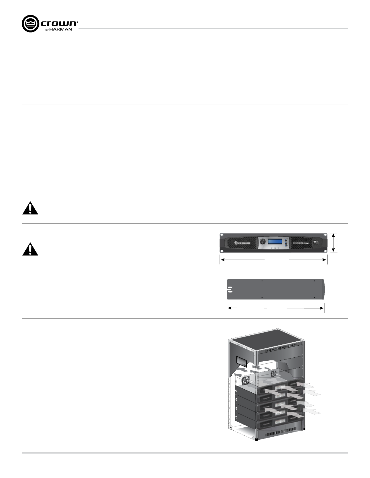
All DCi Network Display Series amplifiers are 3.5 in. (8.9 cm).high and 19 in. (48.3 cm)
wide and 17 in. (43.2cm) deep. (See Figure 1)
Mount the unit in a standard 19-inch (48.3 cm) equipment rack (EIA RS-310B). You can
also place a single amp on a solid, stable surface or stack multiple amps.
NOTE: Amplifiers should be supported at both the front and rear of the rack.
Figure 1
Ensure Proper Cooling
When using an equipment rack, mount units directly on top of each other. Close any open spaces in
the rack with blank panels. (Open spaces will reduce cooling efficiency.) DO NOT block front or rear
air vents.
The rack should be a minimum of two inches (5.1 cm) away from the amplifier, and the back of the
rack should be a minimum of four inches (10.2 cm) from the amplifier back panel.
Air flow is front to back as illustrated in Figure 2.
Fault
Signal
19 In.
48.3 cm
17 In.
3.5 In.
8.9 cm
page 6
Figure 2
Operation Manual
Page 7
DriveCore Install Network Display Series Power Amplifiers
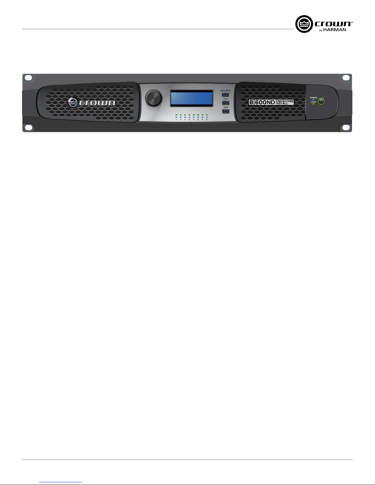
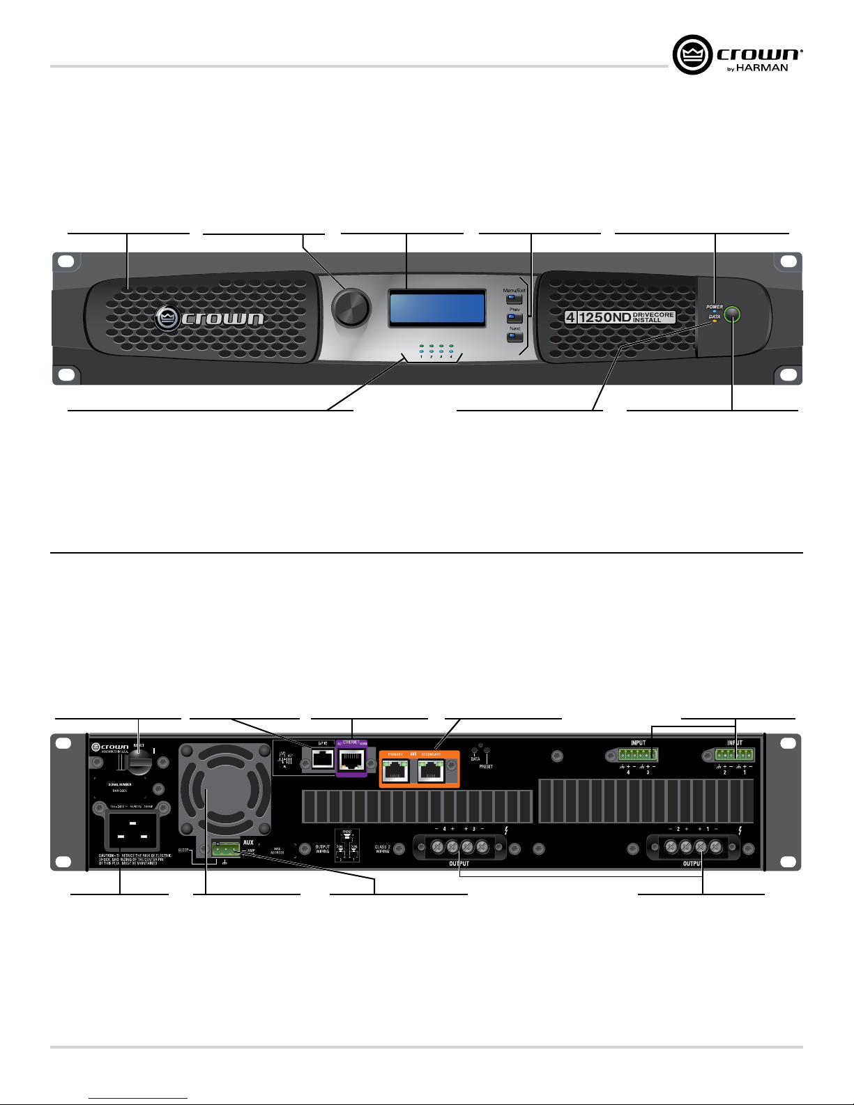
Front Panel Features
Cooling Vent Grille
Filtered venting for cooling
circulation. Do not block or
cover these vents.
Front Panel Control
Allows user to edit and select
amplifier controls in the LCD
Screen.
LCD Screen
Shows enabled presets and
DSP functions in addition
to level clip and thermal
information.
Fault
Signal
Next-Prev-Menu/Exit
Buttons
Allows access to menu items
from the front panel.
Power Indicator (blue)
Illuminates when the amplifier is ON and
acceptable AC line voltage is present.
Blinks when AC line voltage is outside ±10%
range.
Flashes for 4 seconds if Power button pressed
when amplifier is in sleep mode.
Indicators:
Signal Indicators (green): LEDs indicate signal presence
Ready Indicator (blue): When this indicator is activated, the amplifier is
ready to pass audio.
Fault Indicator (red): Flashes when the amplifier output channel has stopped operating
Note: Four channel model shown. Indications per channel pair are identical for 4 and 8 channel models.
Data Indicator (yellow)
Illuminates when data present on the data
network only. AVB connectivity
is not a part of this indicator.
Back Panel Features
AVB Digital Audio
Transport
Primary and Secondary AVB port
for fault tolerance with control
through a separate Ethernet port.
Power Breaker
Resettable breaker to prevent
the amplifier from excessive
current draw.
GPIO
GPIO General Purpose
Input/Output port for
additional control and
monitoring of the amplifier.
Ethernet
For monitoring and control of the
amplifier over Category 5e wiring
through the Audio Architect
software.
Power Button
Power Ring Indicator (Green) - Illuminates
when the amplifier is plugged into a wall
outlet with acceptable power. NOTE: Power
Button is disabled when AUX port Sleep
circuit is used.
Input Connectors
One 6-pin plug-in connector
per input pair. High impedance
balanced. (Refer to Page 8).
AC Power Inlet
Standard 20A IEC inlet
for detachable connector
Universal Power Supply
100 - 240V, 50/60Hz
Cooling Fan Outlet
Outlets for cooling air flow.
Do not block or cover these
outlets.
Operation Manual
Auxiliary Connector
3-pin plug-in type connector,
Enables SLEEP mode and
monitoring of AMP STATUS unless
the amplifier is in any of these
conditions: OFF, SLEEP, or FAULT.
(see Page 31)
Output Connectors
One four-pole touch-proof
terminal strip per channel pair.
Accepts up to 10 AWG wire or
terminal forks.
page 7
Page 8
DriveCore Install Network Display Series Power Amplifiers
Hardware Setup and Conguration
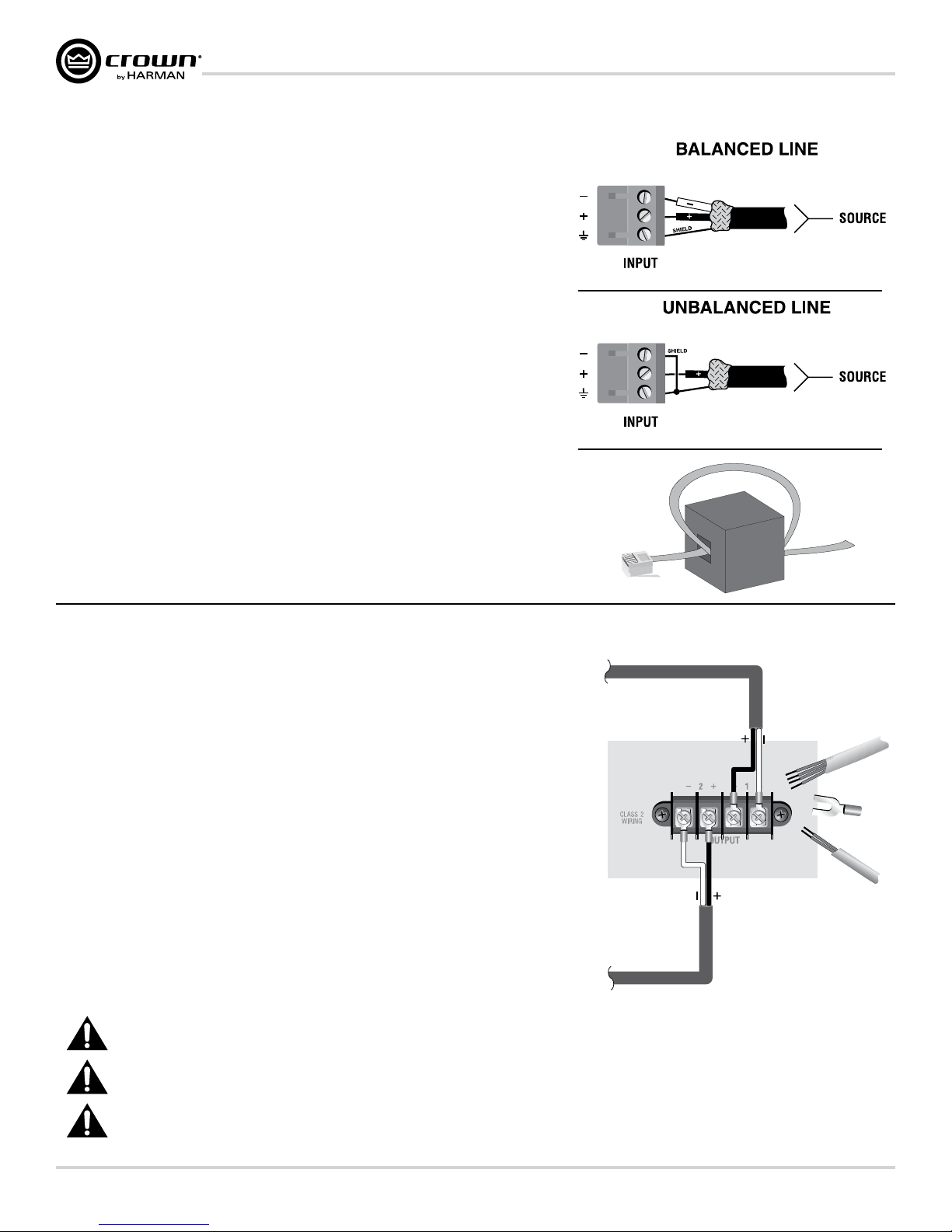
Wire Input Connectors
Crown recommends using pre-built or professionally wired balanced cables (two-conductor
plus shield). Balanced wiring provides better rejection of unwanted noise and hum; however,
unbalanced line may also be used. For more information, refer to the Crown Amplifier
Application Guide, available online at www.crownaudio.com.
Use 6-pin plug-in cable ends at the amp input connectors. A male connector is supplied for
each input of your model of amplifier. Additional connectors are available from Crown
(P/N 5024623).
Figure 3 shows connector pin assignments for balanced wiring and Figure 4 shows connector
pin assignments for unbalanced wiring. Note that for bridged operation, only the connectors for
odd-numbered channels (1,3,5,7) for each bridged pair need be wired.
AVB Connectors
For AVB audio connection, standard Category 6 cabling can be used.
When using the AVB Primary and Secondary input connections, pass the CAT 6 cable twice
through a Ferrite core located as close to the amplifier as possible. This is to ensure compliance
with emissions regulations. See Figure 5.
Figure 3
Figure 4
Figure 5
Wire Output Connectors
Crown has designed an output cover that does not need to be removed to connect the output
wiring.
Crown recommends using the included spade connectors and two- or four-conductor, heavy
gauge speaker wire. You may use terminal forks up to 10 AWG or bare wire for your output
connectors. See Figure 6.
For best results, Crown recommends Panduit part #PV10-10LF-L or equivalent terminal fork.
For bare wire, it is highly recommended that output wiring is tinned. To reduce strain on input
and output wiring, Crown recommends the use of horizontal lacer bars. For best results,
Crown recommends Middle Atlantic part# LBP-4R90 or equivalent horizontal lacer bar.
For low-impedance loads, select the appropriate size of wire based on the distance from
amplifier to speaker.
Distance Wire Size
Up to 25 ft. (7.6m) 16 AWG
26-40 ft. (7.9-12.2m) 14 AWG
41-60 ft. (12.5-18.3m) 12 AWG
> 60 ft (18.3m) 10 AWG
CAUTION: Never use shielded cable for output wiring.
Figure 6
CAUTION: Never connect the speaker return to the chassis of the amplifier, or damage to the amplifier may result.
NOTE: Custom wiring should only be performed by qualified personnel. Class 2 output wiring is required.
page 8
Operation Manual
Page 9

DriveCore Install Network Display Series Power Amplifiers
Connect to AC Mains
Connect your amplifier to the AC mains power source (power outlet) using the supplied AC power cord set. First, connect the IEC end of the cord set to the IEC connector on
the amplifier; then, plug the other end of the cord set to the AC mains.
WARNING: The third prong of this connector (ground) is an important safety feature. Do not attempt to disable this ground connection by
using an adapter or other methods.
Make certain the AC mains voltage and current ratings are sufficient to deliver full power to all amplifiers. If the AC line voltage varies out of an acceptable range, the
amplifier’s power supply turns off and the blue Power LED flashes. The amplifier will turn back on when the AC line voltage returns to safe operating levels.
DCi Network Display Series amplifiers utilize a universal power supply. The AC voltage requirements are 100VAC - 240VAC, 50/60Hz (+/-10%). If the voltage exceeds these
requirements, then the Power LED will flash and the amplifier will stop passing audio until the voltage is within the requirements.
Startup Procedure
When first turning on your amplifier:
1. Turn down the level of your audio source.
2. Turn down the input attenuators of the amplifier.
3. Turn on the “Power” switch. The Power indicator should light.
4. Turn up the level of your audio source to an optimum level. Ensure that at no point in the signal chain is the signal being clipped in any way.
5. Turn up the level controls on the amplifier to the desired loudness or power level.
IMPORTANT: Before making any wiring or installation changes, turn off the amplifier and disconnect the power cord.
For help with determining your system’s optimum gain structure (signal levels) please refer to the Crown Amplifier Application Guide, available online at www.crownaudio.com.
Precautions
Your amplifier is protected from internal and external faults, but you should still take the following precautions for optimum performance and safety:
1. Configure the amplifier for proper operation, including input and output wiring hookup. Improper wiring can result in serious operating difficulties. For
information on wiring and configuration, please consult Page 8 of this manual. For advanced setup techniques, consult Crown’s Amplifier Application Guide
available online at www.crownaudio.com.
2. Use care when making connections, selecting signal sources and controlling the output level. The load you save may be your own!
3. Do not short the ground lead of an output cable to the input signal ground. This may form a ground loop and cause oscillations.
4. Never connect the output to a power supply, battery or power main. Electrical shock may result.
5. Tampering with the circuitry or making unauthorized circuit changes may be hazardous and invalidate all agency listings.
6. Do not operate the amplifier clipping.
7. Do not overdrive the mixer, which will cause clipped signal to be sent to the amplifier. Such signals will be reproduced with extreme accuracy, and loudspeaker
damage may result.
8. Do not operate the amplifier with less than the rated load impedance. Due to the amplifier’s output protection, such a configuration may result in premature
clipping and speaker damage.
Remember: Crown is not liable for damage that results from overdriving other system components.
Operation Manual
page 9
Page 10
DriveCore Install Network Display Series Power Amplifiers
Software Setup
Connect Loudspeakers and Configure for Loudspeaker Load
Determine load impedances and power requirements
Before making any connections, carefully check and review the total impedance for loudspeaker systems to be connected to each amplifier output. If multiple loudspeakers
are connected to one output (in series, parallel or series-parallel) for Low-Z operation, be certain the total system impedance is within allowed specification for the output.
When multiple loudspeakers are connected to one output for Hi-Z operation, be certain total tapped power is below the rated power output for the channel. For additional
information, please consult Crown’s Amplifier Application Guide (available online at www.crownaudio.com).
Note: Illustrations and some text references are for channel pair 1 - 2 only. Connections and settings are identical for channels 3 – 4 on
four-channel models and for channels 5 – 6 and 7 – 8 on eight-channel models. Each channel may be configured independently on multichannel
models.
TM
Set Up and Configuration of the DriveCore™ Install Network amplifiers can be completed through HiQnet Audio Architect
network via the Ethernet connection on the back of the amplifier. Note: the AVB digital audio transport connectors cannot be used for control and monitoring of the amplifier.
To quickly configure your DriveCore™ Install Network amplifier, connect all of the amplifiers and configuration computer to the same network. For more information on
network configuration, please visit www.archimedia.harman.com. In the following example, we will only show amplifiers.
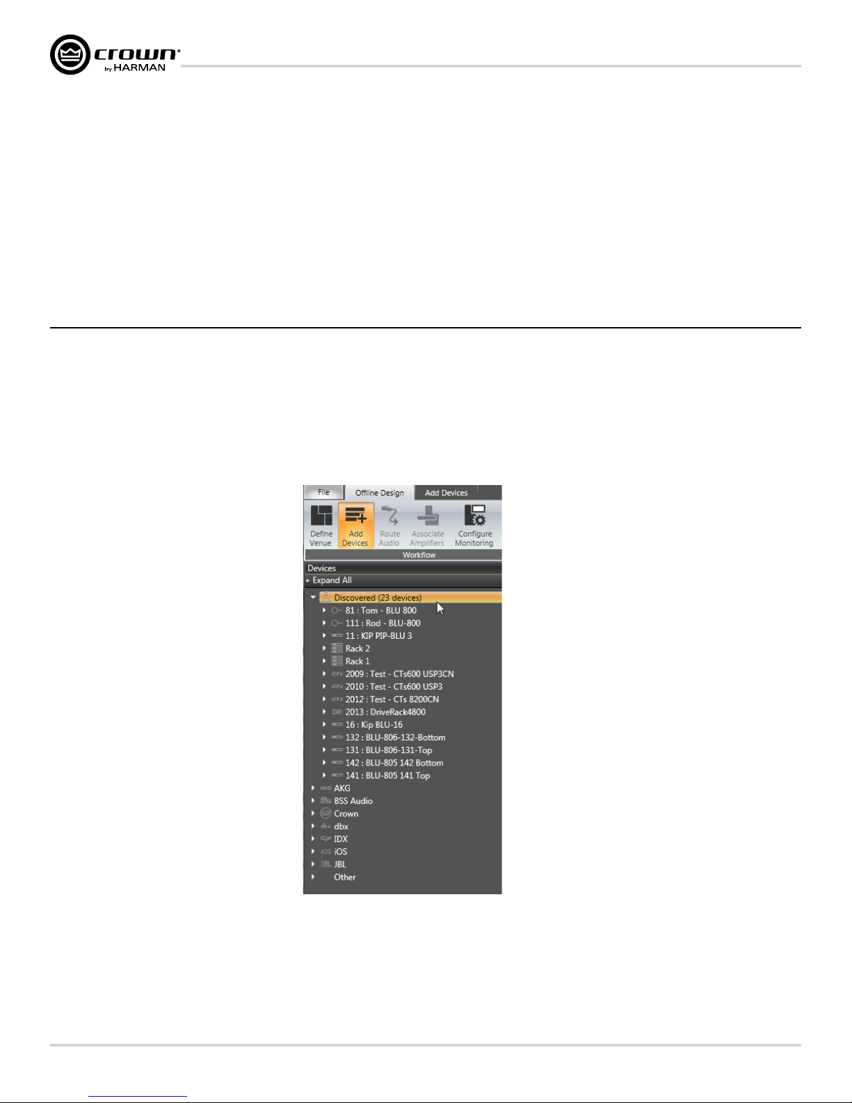
When Audio Architect™ is first loaded, the software will scan the network for HiQnet devices. All devices that are discovered on the network will be found under the ADD
DEVICE tab on the left hand tree menu. If the devices are not found, then the network may not be configured correctly. See Figure 7.
. The amplifier should be connected to a TCP\IP
Figure 7
page 10
Operation Manual
Page 11
DriveCore Install Network Display Series Power Amplifiers
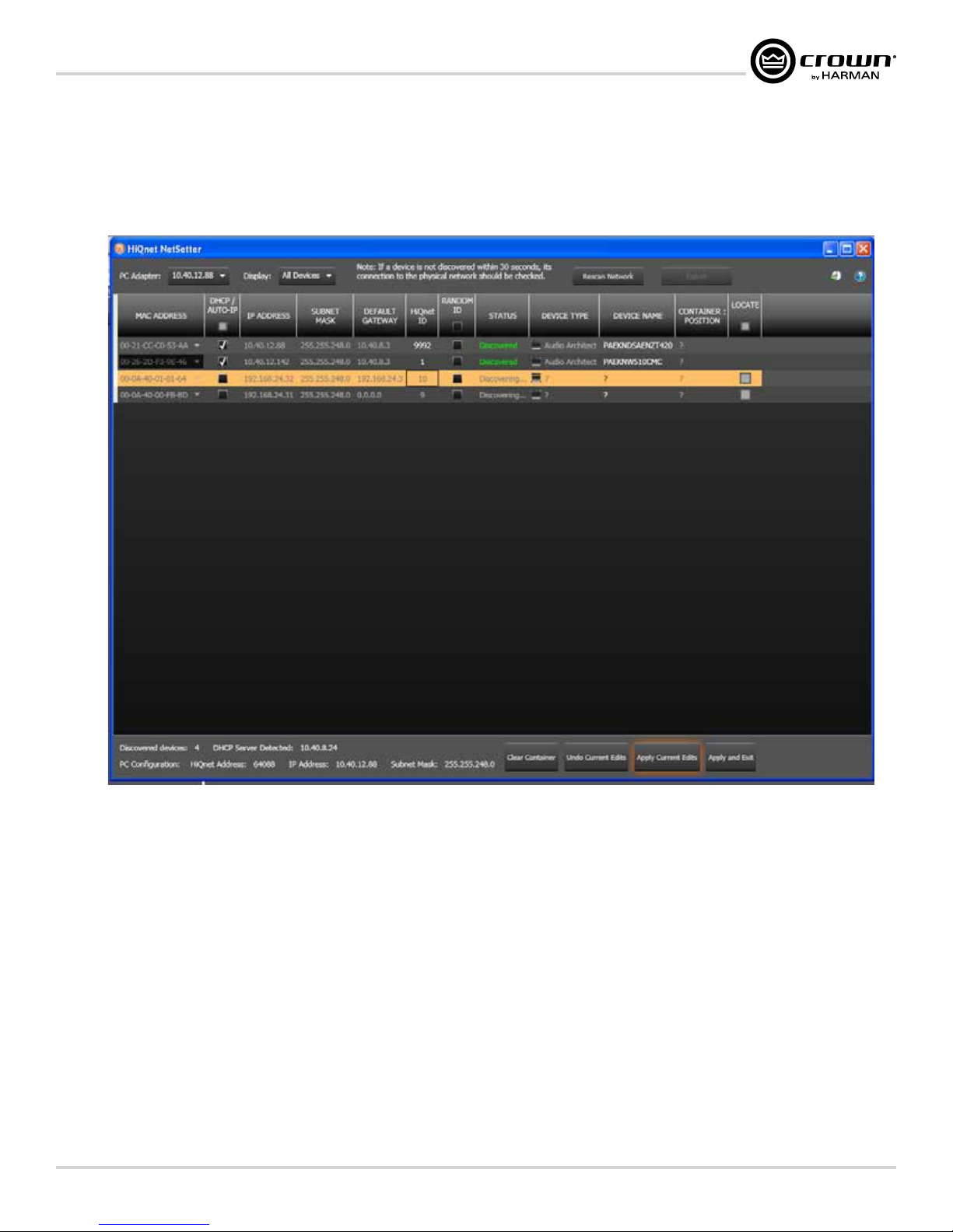
NetSetter
Introduction
The Harman HiQnet NetSetter is a software tool which enables you to discover HiQnet devices and reconfigure network settings in real-time for each device. Its function is to
configure a system of devices to interoperate correctly on the same network and resolve conflicts quickly and easily.
NetSetter Window
Figure 8
The top of the NetSetter page list overall operational functions that are available. They are as follows:
• PC Adapter – A drop list menu that selects the Network Interface Card (NIC)’s adapter that NetSetter will use to attempt to discover HiQnet devices. All available
NIC’s are listed by IP Address. Selecting a new NIC will force a rescan of the network to which the new NIC is connected.
• Display – This menu filters the device in the grid view by:
- All Devices – Default setting. All discovered devices are displayed.
- HiQnet ID conflicts - Only discovered devices with HiQnet address conflicts are displayed.
- IP address conflicts - Only discovered devices with IP address conflicts are displayed.
- All conflicts - Only discovered devices with either HiQnet address conflicts or IP address conflicts are displayed.
- Locked - Only devices in a Locked configuration.
- Discovering-Only devices in the process of being discovered.
- Discovered - Discovered devices with no conflicts.
- DHCP / Auto IP - All devices which have been discovered with DHCP / Auto-IP enabled and those which have been set to use DHCP / Auto-IP on
applying the edits.
• Rescan Network – Clicking this button re-scans the network to which the currently selected NIC is connected.
• Export – The export button brings up a “Save As” window allowing you to save the HiQnet Addresses and IP Configurations of all devices on the
network to a .CSV (Comma Separated Values) format. This allows you to archive the information and open it in a spreadsheet program such as
Microsoft Excel.
Operation Manual
page 11
Page 12
DriveCore Install Network Display Series Power Amplifiers
At the bottom of the NetSetter window is an informational section that list the amount of discovered devices and the IP address of the DHCP Server. There is also information
regarding the PC HiQnet Address, IP Address, and Subnet Mask. There are four buttons that perform the following functions:
• Clear Container - Resets the Container / Position Venue data of the selected device. The action occurs on either Apply Current Edits or Apply and Exit
so that changes may be undone with the Undo Current Edits button.
• Undo Current Edits - Resets any open edits in the grid to the values as currently on the network.
• Apply Current Edits - Confirms any open edits in the grid. Devices update accordingly until connection is reestablished with HiQnet NetSetter.
• Apply and Exit - Confirms and saves any open edits in the grid. The devices update accordingly until connection is reestablished with HiQnet.
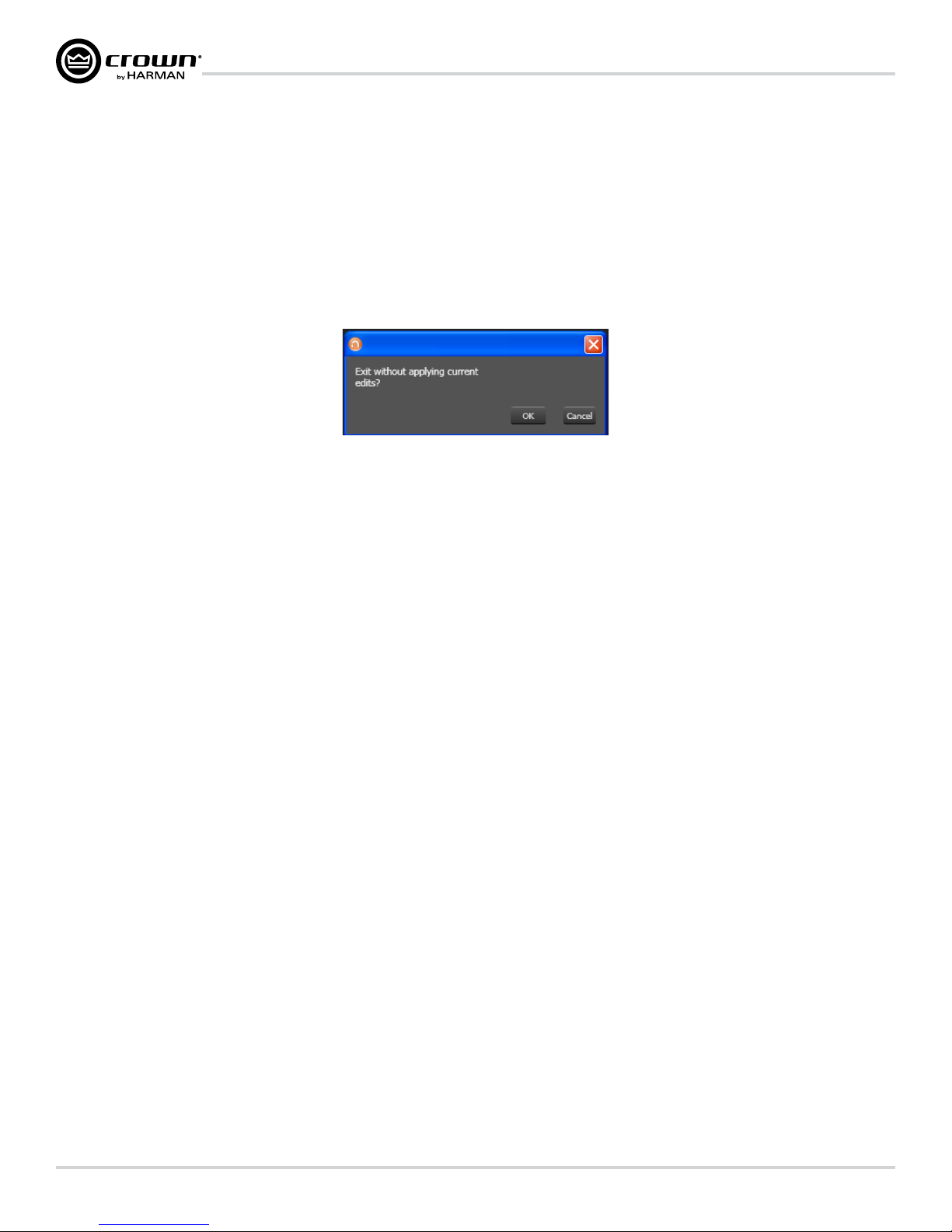
Exit HiQnet NetSetter - If you have made changes to NetSetter, and attempt to exit the program the following window will pop up.
Figure 9
Clicking "OK" will apply the edits you have made since opening NetSetter.
Clicking "Cancel" will return you to the program.
The NetSetter Grid
The grid is divided into 12 sections:
1. MAC Address 7. Random ID checkbox
2. DHCP / Auto-IP checkbox 8. Status
3. IP Address 9. Device Type
4. Subnet Mask 10. Device Name
5. Default Gateway 11. Container : Position
6. HiQnet ID 12. Locate
MAC Address
Displays the MAC Address(es) of the discovered device
If more than one MAC Address is discovered for a single device (HiQnet device MAC Address / AVB card MAC Address etc), the field is represented as a drop list. You may
select between the connected MAC Addresses. The data in this field cannot be edited.
• For a device connected to the same control network with two control MAC Addresses, the MAC Address field will be displayed in red.
DHCP / Auto-IP
If the discovered device is set to use DHCP / Auto-IP, the check box will be checked. If the discovered device is not using DHCP / Auto-IP, you may check the box so it will
do so on applying edits. The device row will then become selected. The device will attempt to have its IP settings configured by DHCP on applying the edits, if no DHCP
server is present the device will attempt to have IP settings configured by Auto-IP.
All devices in the current filter view may be set to DHCP / Auto-IP on by checking the check box in the column header. The individual check boxes for all devices will be
checked. If a single individual check boxes for all devices is subsequently unchecked the column header DHCP / Auto-IP checkbox will be automatically unchecked.
The devices in the current filter view may be set to DHCP / Auto-IP off by unchecking the check box in the column header.
DHCP server status will be among the information displayed at the bottom of the window. If a DHCP server is not detected, the information will read ‘DHCP server not
detected’. Checking a device’s DHCP / Auto-IP check box has no immediate effect on the column sort order.
Once edits have been made, it is critical to click the “Apply Current Edits” or “Apply and Exit” buttons.
page 12
Operation Manual
Page 13

DriveCore Install Network Display Series Power Amplifiers
IP Address
Displays the IP address of the discovered device
A valid IP address may be edited inline. If the edited value scopes the device out of the current Display filter, it will not be visible.
Devices discovered with a conflicting IP Address
A discovered device with an IP Address that conflicts with one that has already been discovered will be displayed in red. A
conflicting IP Address may be edited inline if you wish to change the device IP Address on applying current edits.
If DHCP / Auto-IP is enabled the IP address field may not be edited inline.
Once edits have been made, it is critical to click the “Apply Current Edits” or “Apply and Exit” buttons.
Subnet Mask
Displays the Subnet Mask of the discovered device
The Subnet Mask may be edited inline.
• The device row will be ordered accordingly with the current column sort immediately on successful editing of the field.
• The device row will remain selected.
If DHCP / Auto-IP is enabled the Subnet Mask field may not be edited inline.
Once edits have been made, it is critical to click the “Apply Current Edits” or “Apply and Exit” buttons.
Default Gateway
Displays the Default Gateway of discovered device
May be edited inline.
• The device row will be ordered accordingly with the current column sort immediately on successful editing of the field
• The device row will remain selected
If DHCP / Auto-IP is enabled the Default Gateway field may not be edited inline
If the device is being rediscovered then:
• When the device is not selected, the device Default Gateway address field is displayed but is grayed out, represented in light gray.
• When the device is selected and highlighted in orange the field is represented in dark gray.
Once edits have been made, it is critical to click the “Apply Current Edits” or “Apply and Exit” buttons.
HiQnet ID
Displays the HiQnet address of the discovered device
May be edited inline if you want to change the device HiQnet address.
If the edited value scopes the device out of the current Display filter, it will not be visible. No devices will be selected.
If devices discovered with a conflicting HiQnet Address then:
• The HiQnet ID field of a discovered device with a HiQnet Address which conflicts with a HiQnet
Address which has already been discovered will be displayed in pink.
• A conflicting HiQnet Address may be edited inline if you want to change the device HiQnet Address.
Operation Manual
page 13
Page 14

DriveCore Install Network Display Series Power Amplifiers
• When the device is selected and highlighted in orange the field is represented in red.
• The HiQnet address is not displayed, instead a dash is displayed as grayed out.
Devices not discoverable at the IP level
A device which is not discoverable at the IP level (invalid IP address etc) will not be able to report a HiQnet address. In this instance, the HiQnet ID field will display a ‘?’ to
indicate that the field may exist but that the software does not have enough discoverability of the device to determine the value.
A blank field or ‘-‘ implies the value is null. The HiQnet ID field may not be edited inline.
Once edits have been made, it is critical to click the “Apply Current Edits” or “Apply and Exit” buttons.
Random ID
The device will be given a random HiQnet address. If you want to set the HiQnet address of a device to a random ID, check the Random ID check box. If the check box is
unchecked before applying current edits, the prior HiQnet ID value will be restored.
All devices in the current filter view may be set to Random HiQnet ID by checking the check box in the column header. The individual check boxes for all devices will be
checked if a single individual check boxes for all devices is subsequently unchecked the column header Random ID checkbox will be automatically unchecked.
If all devices in the current filter view are set to Random ID on and the Random HiQnet ID column header check box is checked, all devices may be set to Random ID off by
unchecking the column header check box. The individual check boxes for all devices will be unchecked.
Devices not discoverable at the IP level
A device which is not discoverable at the IP level (invalid IP address etc) will not be able to report a HiQnet address. In this instance, the Random ID check box will be
unavailable.
Status
Displays the current discovery status of the device. The Status field may not be edited. Discovery status hierarchy is as follows:
• Discovered. If a device has a unique IP address and a unique HiQnet address, this condition will be shown unless the device is access controlled. When the
device is not selected, the ‘Discovered’ label is represented in green.
• IP conflict. If a device has an IP Address conflict, this error will be shown regardless of other status notifications. When the device is not selected, the ‘IP conflict’
label is represented in blue.
• HiQnet conflict. If a device has a unique IP address yet has a HiQnet address conflict, this error will be shown regardless of other status notifications. When the
device is not selected, the ‘HiQnet conflict’ label is represented in red.
• Locked. If a device has a unique IP address and a unique HiQnet address, this condition will be shown if the device is access controlled. When the device is not
selected, the ‘Locked’ label is represented in yellow.
• Discovering. This condition will be displayed if the device has had changes made to IP configuration or HiQnet address and HiQnet NetSetter is waiting
to reestablish connection. When a device being rediscovered is not selected, all fields within the device row are displayed but is grayed out,
represented in light gray.
Discovered - The ‘Discovered’ status is determined by the following conditions:
• The device is discoverable at the MAC Address level.
• The device has a valid and unique IP Address (manual or DHCP / Auto-IP).
• The device has a unique HiQnet address.
• The device is not Access Controlled.
IP conflict - The 'IP conflict’ status is determined by the following conditions:
• The device is discoverable at the MAC Address level.
• The device has an IP address which conflicts with another device which has already been discovered by NetSetter.
page 14
Operation Manual
Page 15

DriveCore Install Network Display Series Power Amplifiers
HiQnet conflict - The ‘HiQnet conflict’ status is determined by the following conditions:
• The device is discoverable at the MAC Address level.
• The device has a valid and unique IP Address (manual or DHCP / Auto-IP).
• The device has a HiQnet address which conflicts with another device which has already been discovered by NetSetter.
Locked - The ‘Discovered’ status is determined by the following conditions:
• The device is discoverable at the MAC Address level.
• The device has a valid and unique IP Address (manual or DHCP / Auto-IP).
• The device has a unique HiQnet address.
• The device is Access Controlled.
When the device has been discovered in the Locked state, an Admin password dialog prompt will be displayed. The Admin password must be entered before any field can be
edited.
• A successful login with the Admin password is required to enable fields for subsequential editing.
• This state may need to be reset on rediscovery after applying current edits, requiring the Admin password to be entered again.
Discovering - The ‘Discovering’ status is determined by the following conditions:
• The device had been previously discovered at least the MAC Address level.
• Edits had been made to one or more fields.
• The device is being rediscovered after applying current edits.
Since the sort order automatically updates when a field within the sorted column is updated, the rediscovered device will occupy the same row on rediscovery. Unless DHCP
/ Auto-IP or Random ID has been set prior to applying current edits, in which case the rediscovered device will occupy the appropriate row in the current column sort order.
Device Type
The device class name is displayed, as reported by the discovered device. To the left of each device class name is displayed the brand icon. The software application name is
displayed for discovered PCs running an instance of HiQnet software:
• System Architect
• Performance Manager
• London Architect
The Device Type field may not be edited inline.
Devices not discoverable at the IP or HiQnet level
A device which is not discoverable at the IP level (invalid IP address etc.) or HiQnet address level (HiQnet address conflict etc) will not be able to report its class name. In
this instance, the Device Type field will display a ‘?’ to indicate that the field may exist but that the software does not have enough discoverability of the device to determine
the value.
A blank field or ‘-‘ implies the value is null.
Operation Manual
page 15
Page 16

DriveCore Install Network Display Series Power Amplifiers
Device Name
The user-definable Device Name is displayed, as reported by the discovered device.
• May be edited inline if you want to change the Device Name.
• May not be edited for discovered PCs running an instance of HiQnet software.
Devices not discoverable at the IP or HiQnet level
A device which is not discoverable at the IP level (invalid IP address etc) or HiQnet address level (HiQnet address conflict etc) will not be able to report its Device Name.
In this instance, the Device Name field will display a ‘?’ to indicate that the field may exist, but that the software does not have enough discoverability of the device to
determine the value.
A blank field or ‘-‘ implies the value is null.
Once edits have been made, it is critical to click the “Apply Current Edits” or “Apply and Exit” buttons.
Container : Position
The Container and Position Venue Data is displayed (separated by a colon), as reported by the discovered device. The field is left blank for discovered PCs running an
instance of HiQnet software.
• System Architect
• Performance Manager
• London Architect
The Container / Position Venue Data may not be edited inline.
A selected device may have its Venue Data cleared (including all Building, Floor and Room Venue data) by pressing the Clear Container button. This action takes place on
applying current edits only and can be undone with the Undo Current Edits button.
Devices not discoverable at the IP or HiQnet level.
A device which is not discoverable at the IP level (invalid IP address etc) or HiQnet address level (HiQnet address conflict etc) will not be able to report its Device Name. In
this instance, the Device Name field will display a ‘?’ to indicate that the field may exist but that the software does not have enough discoverability of the device to determine
the value.
A blank field or ‘-‘ implies the value is null.
Locate
Clicking in the Locate column for a device will put the corresponding device on the network into a Locate state, and the Locate icon will be displayed.
• Clicking an active Locate icon will disable the Locate state for the device.
• Disabling the Locate state from the device will clear the icon.
• Devices may be put into Locate state independently from selection so that more than one device can be located at any one time.
page 16
Operation Manual
Page 17

DriveCore Install Network Display Series Power Amplifiers
Offline/Online Operation
Audio Architect has two define modes of operation: Online and Offline. Offline operation allows the system to be configured without real time changes to the system. In this
mode, changes have to be sent to the edited device. In Online mode, changes to amplifiers are made real time.
When Audio Architect first opens, the Offline Design Tab is the ribbon presented, and the Device Toolbox appears on the left and an empty Properties window is at the
bottom. The Add Devices box is highlighted. When going Online, it may be necessary to Match Devices and/or Synchronize Venue.
Figure 10
Match Devices allows users to associate amplifiers within their venue design to amplifiers on the network. In the Match Devices tab, the following options are available:
Figure 11
• Refresh Networking: Clicking this button will temporarily take Audio Architect offline, then restart the network.
• Match
- Auto-Venue: Automatically enables matching between all the devices in the Audio Architect venue.
- Detach: Removes the device's virtual connection from Audio Architect.
• Editing
- Undo: Erases the last change done, reverting to the previous state.
- Redo: Re-establishes the previous state.
• Show – The checked items are displayed along side the appropriate devices in the venue; Device Names, Rack/Array Names, HiQnet Addresses, and IP
Addresses. In Synchronize Venue, each device will be shown with either a Receive icon or a Send icon.
• Receive – Device settings will be downloaded to the Audio Architect.
• Send – Device setting will be sent from Audio Architect to the device.
When going Online, the following options are possible:
1. If one or more devices in the Venue are not matched AND corresponding devices are available on the network, going online lands in Match Devices mode.
2. If all the devices in the Venue are matched, going online lands in Synchronize Venue mode. In Synchronize Venue mode, the user is given the option to either
Send data from Audio Architect to the device or Receive data from the device to Audio Architect.
3. If no devices require to be synced, going online lands in Run Venue mode.
Operation Manual
page 17
Page 18

DriveCore Install Network Display Series Power Amplifiers
Each amplifier can be dragged into the room window. Each device will have a IP address listed on the left of the amplifier and a Name ID on the right on the amplifier. The
Name ID can be edited in the properties menu at the bottom of the page. The number to the left of Name ID is the HiQnet Device Address. The green circle only indicates that
the amplifier has been discovered on the network. The small box located below the rack allows quick access to amplifier factory panels. These panels include the following
items. Note: When a device is added to the window, it is automatically removed from the "Discovered".
• Factory Master Panels
• Monitor Panels
• Meter Panels
• Level and Mute Panels
Figure 12
Double clicking an amplifier will access the amplifier factor control panel. At this point, Audio Architect is in OFFLINE MODE. In OFFLINE MODE, amplifier changes are
not made in real time and will need to be sent to the amplifiers. Amplifier changes can also be sent in real time in ONLINE MODE. To go to ONLINE MODE, click on the GO
ONLINE tab in the Workflow bar menu. RECEIVE and SEND buttons will appear for each device, rack, and room in the design. This gives the user the option to just update a
single device, all devices in a rack or an entire venue. Click SEND to load the settings made in Audio Architect to the amplifier. Click RECEIVE to read the settings off of the
amplifier to be reflected in Audio Architect.
Figure 13
page 18
Operation Manual
Page 19

DriveCore Install Network Display Series Power Amplifiers
Software System Conguration
Amplifier Mode Settings
Figure 14 (above) shows the DriveCore Install 2 channel configuration page. The 4 and 8 channel amplifier configuration pages have the same feature set.
The DriveCore Install Network amplifier includes Digital Signal Processing (DSP), multiple input/output routing options and a comprehensive diagnostics feature set.
All of these features can be adjusted in from the configuration page.
The DCi Network Display Series amplifiers are very capable and flexible amplifiers. In the Amplifier Mode Setting window, the following items can be adjusted:
• Hi-Z/Low-Z on an individual channel basis
• 70Vrms or 100Vrms operation
• Any analog input can be sent to any amplifier output
• Mono Bridge Output - Output pairs can be bridged for mono operation
Hi-Z/Low-Z
The DriveCore Install Network amplifiers are capable of High-Z and Low-Z outputs. Each individual channel is capable of Hi-Z or Low-Z operation. To select Hi-Z or Low-Z
operation, double click on the mode button, the Amplifier Mode Setting Window will open (see Figure 15). Note: Choosing 70Vrms or 100Vrms is an amplifier global
setting, and affects all output channels selected for High-Z operation.
Global
Channel
Specific
Figure 15
Operation Manual
page 19
Page 20

DriveCore Install Network Display Series Power Amplifiers
Software System Conguration
Cascading Inputs
Cascading the analog inputs, or "Y-ing channels" gives more flexibility to the installation of this amplifier (See Figure 16). One input can be used to drive some or all of the
amplifier outputs. NOTE: By cascading the inputs, the corresponding input DSP functions for individual channels will be removed and only the output DSP functions will be
available (See Figure 17).
Figure 16 Use the "Y 1+2" etc. check boxes to cascade channel inputs.
Figure 17 With the "Y 1+2" box checked, both output Ch.1 and Ch.2 are fed by input Ch.1 and input processing is organized accordingly.
page 20
Operation Manual
Page 21

DriveCore Install Network Display Series Power Amplifiers
Software System Conguration
Bridge Mono Operation
The DCi Network Display Series amplifier outputs can be bridged to increase the power and voltage available at the output of the amplifier. The amplifier can be bridged in
the Amplifier Mode window. By selecting the bridging option, only the first input channel will need to be wired. (See Figure 18). Low-Z and High-Z options are still available.
NOTE: If the amplifier output is in bridge mono and the High-Z option is selected, the amplifier will produce 140Vrms or 200Vrms.
Figure 18 Check the Bridge Mono 1+2 box to bridge the output of the amplifiers.
Figure 19 By selecting Mono Bridge output, only one channel in the channel pair DSP will be available.
Operation Manual
page 21
Page 22

DriveCore Install Network Display Series Power Amplifiers
Software System Conguration
Low-Z (8, 4 or 2 Ohm) Output Operation
Typical input and output wiring, along with Audio Architect
software settings are shown in Figures 20 and 21.
INPUTS: Connect the input with wiring in place for each
channel. If the same signal is to drive both outputs of a
channel pair (“mono”), the input signal can be sent to
adjacent amplifier channels.
OUTPUTS: Maintain proper polarity (+/–) on output
connectors. Connect the Channel 1 speaker’s positive (+)
lead to amplifier Channel 1 positive terminal;
repeat for negative (–). Repeat Channel 2 wiring as for
Channel 1, and for any subsequent channel pairs on
multichannel models. Refer to Page 8
for output connector terminal assignments.
Figure 21 Amplifier is preconfigured for Low-Z, Dual Output.
Figure 20 System Wiring Dual Mode
Always route the input and output wires in separate bundles.
page 22
Operation Manual
Page 23

DriveCore Install Network Display Series Power Amplifiers
Software System Conguration
Bridge Mode (16, 8, or 4 Ohm) Output Operation
Typical input and output wiring, along with software settings are
shown in Figures 22 and 23.
INPUT WIRING: If using analog inputs, it is only necessary to wire
the odd number inputs.
OUTPUTS: Connect the speaker across the positive terminals of
each channel pair. Do not use the negative terminals of
the channel pair when the pair is being operated in Bridge-Mono
mode.
Figure 22 System Wiring Bridge Mode
Figure 23 The bridge mono checkbox must be checked for proper operation
Always route the input and output wires in separate bundles.
Operation Manual
page 23
Page 24

DriveCore Install Network Display Series Power Amplifiers
Software System Conguration
Dual Mode Hi-Z (70V/100V) Mode
Typical input and output wiring, along with software
settings are shown in Figures 24 and 25.
A 35Hz high pass filter is selected automatically
when the amplifier channel is in Hi-Z or Bridged Hi-Z
mode. Remember, DCi amplifiers allow each channel
Hi-Z or Low-Z mode of operation to be selected
independently, while 70V/100V selection is global.
Figure 24 System Wiring for 70V/100V Operation
Figure 25 Radio buttons control Low-Z/High-Z on a per channel basis. 70Vrms and 100Vrms radio buttons
control High-Z point for the entire amplifier.
Note: 70/100V is global, while Low-Z/Hi-Z is per output channel
Always route the input and output wires in separate bundles.
page 24
Operation Manual
Page 25

DriveCore Install Network Display Series Power Amplifiers
Software System Conguration
Bridge Mode Hi-Z (140V/200V)
Typical input and output wiring, along with software settings
are shown in Figures 26 and 27.
INPUTS: Connect the input to the odd-numbered channels
(1,3,5,7) only. Even-numbered inputs are disabled when the
Bridge Mono mode is active.
OUTPUTS: Connect the speaker across the positive terminals
of each channel pair. Do not use the negative terminals of the
channel pair when the pair is being operated in Bridge-Mono
mode.
Figure 26 System Wiring for 140V/200V Operation
Figure 27 Operation mode for 140Vrms or 200Vrms.
Always route the input and output wires in separate bundles.
Operation Manual
page 25
Page 26

DriveCore Install Network Display Series Power Amplifiers
General Purpose In/Out Control Port
DriveCore Install Network amplifiers come with a 2-in, 2-out General Purpose In/Out (GPIO) control port in the form of a 6 position RJ-11 connector. The Control Port has
multiple functions and uses which include preset selection, and gain control among others.
Hardware Specification
Inputs are analog capable of either binary or analog control of a State Variable (SV) within the amplifier. Outputs are binary only that represent an SV of the amplifier.
Additionally, outputs can be controlled independently (on/off, polarity) via the software.
PIN 1: Output 1. 0VDC to +3.3VDC output. Output impedance = 1KΩ pullup to +3.3V.
PIN 2: Output 2. 0VDC to +3.3VDC output. Output impedance = 1KΩ pullup to +3.3V.
PIN 3: Input 1. 0VDC to +3.3VDC input. Logic = TTL thresholds. Analog = full scale 0-3.3V. Input impedance > 20KΩ.
PIN 4: +3.3VDC output. ILIMIT = 30mA. Output impedance = 100Ω to +3.3V.
PIN 5: Input 2. 0VDC to +3.3VDC input. Logic = TTL thresholds. Analog = full scale 0-3.3V. Input impedance > 20KΩ.
PIN 6: GND.
Configuration of the Control Port Inputs
2 inputs: Can be variable (connect to pot) binary (connect to switch) or multilevel connect to rotary switch and voltage steps.
• Audio Architect is used to assign up to 40 SV's to each input.
• An input mode is selected.
SET - Sets the assigned SV(s)to a specific value.
VARY - Continuously varies the assigned SV(s) by a specified value, typically a volume pot application.
PRESET - Recalls the max preset in one state (high) and the min preset in the other state (low).
BUMP - Similiar to vary but implemented with a button instead of a pot. A high level will bump the assigned SV(s) by a specific value.
AUTOBUMP - Similiar to bump, but will continue to bump the assigned SV(s) value as long as the input state is changed.
Right click on a DCIN in the venue. Select “Configure Control Ports”. A new tab labeled “(amplifier name) – Control Ports” will open.
Software Parameters
High Limit – Available only on input, and only for parameters in “Analog Input” mode. This field determines the value that the selected assigned parameter will assume
when the control port input is at the maximum end of its range.
Input – Selects between control port inputs, labeled 1 and 2.
Low Limit – Available only on input, and only for parameters in “Analog Input” mode. This field determines the value that the selected assigned parameter will assume
when the control port input is at the minimum end of its range.
Mode – For the control port input, the Mode field determines how the assigned parameters will be controlled. For the control port output, the Mode field determines the
conditions under which the output status will change.
Off Value – Available only on input, and only for parameters in “Direct Action” mode. Determines what the value of the selected assigned parameter will be when the
control port input is logic “Low”.
On Value – Available only on input, and only for parameters in “Direct Action” mode. Determines what the value of the selected assigned parameter will be when the control
port input is logic “High".
Output – Selects between control port outputs, labeled 1 and 2.
Output Polarity – Enables selection between “Normal” and “Inverted".
Parameter Assignment – List of parameters that are currently assigned to a given control port input.
page 26
Operation Manual
Page 27

DriveCore Install Network Display Series Power Amplifiers
General Purpose In/Out Control Port
Figure 28 Control Port Configuration Page.
In the Venue Explorer, select and expand the device for a list of objects. Expand an object for a list of state variables (SV’s) within the object. A state variable can be added to
the control port input assignment by clicking and dragging with the mouse into the “Parameter Assignment” tab for either input 1 or 2.
Figure 29 Assigning the “Current Preset” parameter to Control Port Input 1.
Once an SV has been added, its type will determine which MODE options become available. If a binary SV has been assigned, only the “Direct Action” mode is selectable,
and the “ON VALUE” and “OFF VALUE” parameters can be toggled as desired. However, if a non-binary SV is added, the “Analog Input” Mode becomes available. In this
mode, the ON and OFF VALUE fields are unused, and the “HIGH LIMIT” and “LOW LIMIT” fields appear and become accessible. The LIMIT fields allow control of an SV over
a specified range.
Operation Manual
page 27
Page 28

DriveCore Install Network Display Series Power Amplifiers
General Purpose In/Out Control Port
Additional state variables can be added to a given control port input by selecting the SV and dragging on top of a previously assigned row of the desired input.
However, once an SV has been assigned and the MODE has been set, any subsequent SV that is added must function in the same MODE. Up to 40 SV’s can be assigned to a
given input.
Figure 30 Configuring Input 1 to control Processing Output Faders for Channels 1 – 2, and Input 2 To control Processing Output Mutes for Channels 1 – 2.
An assigned state variable can be removed by highlighting and selecting “Remove Assignment” in the upper left hand corner.
page 28
Operation Manual
Page 29

DriveCore Install Network Display Series Power Amplifiers
General Purpose In/Out Control Port
Configuration of the Control Port Outputs
2 outputs: Binary only.
• There is a polarity control on each output so that it may function as active-high or active-low.
• Output Mode 1 - Manual: Controlled directly by the output enable button.
• Output Mode 2 - Report Errors: Active when any enabled error is reported. The indicator will stay on for up to 60 seconds after the error is cleared. Errors include:
Load Supervision
AC Line Voltage is out of range
Hardware Protection(faults)
Over temperature (any channel or power supply)
Amp output clipping
Processing output clipping (off by default)
Analog Input clipping (off by default)
• Output Mode 3 - Report online status: Active when HiQnet connection is lost. The length of time to wait for a time out is user adjustable, default=60sec.
The Control Port output configuration options can be found directly below those for the input. No parameters can be assigned to the outputs. Instead, there are three modes
available: Manual, Report Errors, and Report Online Status. Manual mode enables direct control over the selected output. In “Report Errors” mode, the output status will
change if any errors are reported to the network, such as clip errors, temperature errors, line voltage errors, etc. Finally, in “Report Online Status” mode, the output status will
change if no network communication is detected for at least 60 seconds. The control port output does not turn off right away when reporting errors or online status. There
are several reasons for this. The online status does not change quickly, it can take up to 60sec to drop offline or to recover. In these modes, the output is intended to be used
with devices such as a backup amp switcher or an electro-mechanical system. We want to prevent this output from toggling on/off quickly. It may take the output up to 90
seconds to recover (i.e. switch states) from an error or loss of connection.
Operation Manual
page 29
Page 30

DriveCore Install Network Display Series Power Amplifiers
General Purpose In/Out Control Port
Figure 31 Control Port Output Configuration.
NOTE: that in all modes, the polarity of the binary output can be toggled under the OUTPUT POLARITY tab, where “Normal” or “Inverted” can be selected.
page 30
Operation Manual
Page 31

DriveCore Install Network Display Series Power Amplifiers
Aux Port/Sleep/Amp Status
AUX Port
The AUX port can be used for basic monitoring of the amplifier and for remote standby. The port is a 3 pin block connector with pin-2 used as ground.
Sleep
The amplifier can be put to sleep by connecting pins 1 and 2 on the AUX port. When applying this connection, the amplifier will shut down and remain in sleep until the
connection between pins 1 and 2 is open. While the amplifier is in sleep, the front panel power button is disabled. When the connection between pins 1 and 2 is open,
the amplifier will revert to its last configuration and begin to output audio within 20 seconds. Communication via the network will take as long as the network
interface card boots. If the front power button is pressed while the amp is in sleep mode, the blue power indicator will blink twice.
Amp Status
AMP STATUS can be used for basic monitoring of the amplifier. Monitoring of the amplifier can determine if the amplifier is operating within optimal parameters or if the
amplifier has been shut off or is in fault. Between pins 2 and 3, there will be either a +5VDC potential or a 2Hz square wave (heart beat). This option can be found in the AMP
INFO button on the main amplifier page.
Operation Manual
page 31
Page 32

DriveCore Install Network Display Series Power Amplifiers
Advanced Operation
Introduction
Your DCi Network Display Series amplifier has a wide variety of onboard Digital Signal Processing (DSP). HiQnet Audio Architect software lets you adjust the DSP settings,
such as filter slope, compression ratio, EQ frequency bands, and so on.
A preset is a group of DSP settings that configure the amp for a specific application. For example, you might use one preset that optimizes the amp’s
DSP for a JBL tri-amplified speaker setting. You might use another preset that sets up the DSP for a stereo pair of loudspeakers of your choice. You can
choose any of 20 presets.
Amplifier Presets and Speaker Tunings
Preset 1 is the factory default preset and cannot be overwritten. It sets up the amplifier for pass-thru operation with no DSP features enabled. The DCi Network Display
Series amplifier works with two types of presets:
User Presets – Using Audio Architect, you can create your own custom DSP presets, label them and send them to the DCi Network Display Series amplifier. The
amp stores those presets in firmware.
Downloadable Presets – Available for download from a variety of manufacturers, these presets are configured for optimal performance and can be sent to the
amplifier via Audio Architect.
User Presets
User presets are DSP presets that are configured manually. The following three steps outlines setting up User Presets:
1. Adjust the DSP settings as desired in the Audio Architect software.
2. Save this group of settings as preset, you will be prompted to name it.
3. Download the preset to the DCi Network Display Series amplifier. See the software Help file for details. As soon as you save the setting as a preset, it is sent to
the amplifier.
page 32
Operation Manual
Page 33

DriveCore Install Network Display Series Power Amplifiers
Advanced Operation
Speaker Tunings
Crown and JBL engineers have designed DriveCore Install DSP settings that are optimized for various JBL loudspeakers. Speaker tunings can be downloaded at the
following website: www.jblpro.com. An improved speaker tuning approach has been developed for the DriveCore Install Network Series. The system is software library
based rather than device preset based. The new approach offers significant benefits:
• Unlimited number of tunings organized into an unlimited number of libraries.
• Simple and fast drop-down tuning recall/store/delete within device GUI.
• Channel/band specific tunings – no more managing tunings across channels or amp chassis. Also yields logical one-to-one correlation of amp output
to transducer/band.
• Faster tuning load/store times – much easier to compare and run A/B tests on multiple tunings without audio dropouts.
• Library based – allows logical groupings and archiving of similar tunings (e.g. Screen Array Series or VTX Series, etc.).
• Tunings can be held within but are de-coupled from device presets. Eliminates concern of accidentally deleting or changing other device parameters –
speaker tunings only contain the parameters required for speaker tunings! Now presets can be used for complete device configurations – as intended.
• Simpler and faster third-party and user tunings and libraries development – more people will be willing to develop custom or 3rd party tunings.
• Single panel access to all required tuning parameters – easier/faster to create/modify tunings.
Speaker Tuning Panel
A new “speaker tuning” icon is implemented on the main device panel for each channel of DCi amplifiers. Double-clicking the speaker tuning icon will open the basic
Speaker Tuning Panel (STP). See Figure 32.
Figure 32 Basic Speaker Tuning Panel.
Basic STP functions are:
Recall
Loads the selected tuning from the working library (drop-down list) into the respective channel.
Store
Stores the STP settings from the respective channel into the working library with specified user name. The stored tuning is then available in the drop-down list for any
other channel or amp.
Delete
Deletes the selected tuning from the working library.
Speaker Manufacturer
This parameter displays a text description of the respective speaker manufacturer (i.e.JBL, Custom, etc.). The data for this parameter is stored within the tuning and also
within the device settings.
Speaker Model
This parameter displays a text description of the respective speaker model (i.e.3722, Three-Way, etc.). The data for this parameter is stored within the tuning and also
within the device settings.
Band
This parameter displays a text description of the respective tuning band (i.e. LF, MF, HF). The data for this parameter is stored within the tuning and also within
the device settings.
Tool Tips
The Mfr, Model and Band text fields are displayed in the tool tip box when the mouse is hovered over the respective channel Speaker Tuning Icon.
Operation Manual
page 33
Page 34

DriveCore Install Network Display Series Power Amplifiers
Advanced Operation
Advanced STP functions are available to create/modify speaker tunings. Holding CTRL-ALT-SHFT while double-clicking the speaker tuning icon opens the advanced panel.
See Figure 33.
Figure 33 Advanced Speaker Tuning Panel
The advanced panel includes every parameter implemented in a speaker tuning:
1. All parameters from basic panel (Recall, Store, Load, Delete, Mfr Name, Model, Band)
2. Crossover Filters (HP lower band-edge, LP upper band-edge, 18 types up to 48dB/oct)
3. EQ Filters (8 second order filter sections, 11 types, full parametric control)
4. LevelMax Limiter Suite (Peak, RMS, Thermal Limiters, Auto/Manual modes)
5. Delay (Fine adjustable from 0S to 0.1S, Coarse adjustable from 0S to 2S)
6. Band Gain (adjustable from -100dB to +20dB in 0.5dB steps)
7. Polarity/Invert
Speaker Tuning Libraries
The new system uses software based Speaker Tuning Libraries. Audio Architect manages these libraries within the device DLL. A library can contain any number of tunings.
Audio Architect can manage any number of libraries. The library system implemented includes:
Working Library
The working library is opened and active when opening any Speaker Tuning Panel. The working library is automatically updated with the latest stored tunings/settings when
exiting the open STP. Audio Architect is installed pre-configured for DCi amplifiers with a working library previously loaded with JBL Screen Array tunings from the JBL
Master Screen Array Library. Note: Multiple STP's can be opened but only the last parameters on the last panel closed are saved to the working library.
page 34
Operation Manual
Page 35

DriveCore Install Network Display Series Power Amplifiers
Advanced Operation
JBL Master Screen Array Library
This library is included with Audio Architect at install. The tunings in this library were developed and validated against previous same tunings for Crown DSI amplifiers. It is
read-only to prevent over-write. At any time, a user can load this library to access reference JBL tunings for these devices.
User Libraries
At any time, the user may save the current working library to a custom user library file.
Loading a Library
Click on the File/Open > Speaker Tuning dialog on the device main panel to open and load an existing library file into the working library. This action replaces the current
working library. Any changes not saved to the existing working library will be lost.
Saving a Library
Click on the File/Save > Speaker Tuning dialog on device main panel to save the current working library to any filename. Note: JBL files are write-protected/read-only and
cannot be over-written.
Library File Locations
The file location and naming conventions for all speaker tuning libraries is:
• Windows 7 path C:\ProgramData\Harman Professional\Audio Architect\
• Windows XP path c:\Documents and Settings\All Users\Application Data\Harman Professional\Audio Architect\
Library Filename Conventions
The general file names are:
• Working Library: Crown Library.DCi Series.SpeakerTuning
• JBL Screen Array Library: JBL Master Screen Array Library.DCi Series.SpeakerTuning
• User Libraries: Any_user_file_name.DCi Series.SpeakerTuning
Operation Manual
page 35
Page 36

DriveCore Install Network Display Series Power Amplifiers
Advanced Operation
Software-Controllable Onboard DSP
Crown DriveCore Install Network amplifier have Digital Signal Processing built into the amplifier.
When you use an DriveCore Install Network amp, the loud speaker processors, crossovers, limiters and delays are in the onboard DSP – so discrete rack mount devices are
not needed. This drastically cuts setup time, commissioning, rack space and costs. The DriveCore Install Network DSP can be monitored and controlled with a computer
running Audio Architect software, and connected to the amplifier Network Connector by a Category 5 Network cable.
Some applications for this DSP are:
• Configure signal flow
• Optimize system gain structure
• Configure speaker configurations (set the drive levels, frequency bands, delays and limiting for your particular speakers)
• Configure EQ, filtering, and much more.
See the Audio Architect Help files for more detailed information.
Figure 34 Main DCi Interface
On the left of this screen is the Input and Output Signal Level Monitor (explained later on this page). On the right side are rows of DSP selection buttons for each channel.
When you double click on a button, a control panel opens for that button’s function.
Also on the right are buttons that open control panels for these functions:
• Amplifier mode
• Signal generator (pink noise and sine wave)
• Amplifier information
• Recall and store presets
• Preset manager
• Apply to others (apply this amplifier’s DSP settings to other devices)
We’ll explain each of these functions on the next several pages.
page 36
Operation Manual
Page 37

DriveCore Install Network Display Series Power Amplifiers
Advanced Operation
Input Level, Faders, Mute, Link, I/O Level Meters, and Indicators
Figure 35
This panel is on the left side of the DriveCore Install Network main control panel shown above. Channels 1, and 2 Level Controls set the input signal level of each channel.
Each channel can be muted, and both faders can be linked with the Link button.
Input Signal Level Meter (green)
The measurement range is from 0dBFS to –40dBFS with 0.5dB resolution. Each audio channel has the following monitors:
• Switched Audio Input: This meter shows only the switched (selected) audio input after the Input Audio Router.
• Clip Indicator
• Peak + RMS levels
Output Signal Level Meter (blue)
The measurement range is from 0 dB to –40 dB with 0.5 dB resolution. The monitors are scaled so that 0 dB is referenced to the full rated output voltage of the amplifier. The
wider left meter is rms and the right meter is peak for each channel. An output clip indicator is provided.
Indicators
• Temp: Lights if the temperature of the amplifier is too high and the amplifier is near shutdown.
Green: Thermal headroom used up is less than 59%.
Yellow: Thermal headroom used up is 60-80%.
Red: Thermal headroom used up is more than 81%.
• Limit: Lights when the amplifier signal is being limited.
• Load: Lights when the load impedance is out of range.
• Ready: Lights when the amplifier is on and ready to supply power.
• Fault: Lights when the amplifier is in a fault mode service may be required.
Operation Manual
page 37
Page 38

DriveCore Install Network Display Series Power Amplifiers
Advanced Operation
Input Delay and Driver/Output Delay
Input delay includes up to 2 seconds of delay. Output delay is typically used for driver alignment. Up to 0.1 seconds of output delay is provided. See Figure 36.
Figure 36
Input/Output Equalization
These screens let you adjust channel equalization for up to 8 frequencies. You can select filter type, frequency, gain, and bandwidth in octaves or Q as set by the user
preferences in Audio Architect. Changes to the equalizer’s frequency response can be done by typing in parameters or by click-dragging the response curve. See Figure 37.
Figure 37
page 38
Operation Manual
Page 39

DriveCore Install Network Display Series Power Amplifiers
Advanced Operation
Crossover Filters
The Crossover section lets you use infinite impulse response (IIR) Crossover filter.
Each audio channel has three separate places where filters can be placed in the
system: input EQ, Crossover, and Output EQ. Up to 16 EQ filters per
channel are available, plus crossover filters. Each filter has up to +/-24dB of gain.
The following filters are available:
• Lowpass & Highpass:
– Bessel 12dB/oct, 18dB/oct, 24dB/oct, 30dB/oct, 36dB/oct, 42dB/oct, 48dB/oct
– Butterworth 12dB/oct, 18dB/oct, 24dB/oct, 30dB/oct, 36dB/oct, 42dB/oct, 48dB/oct
– Linkwitz-Riley 24dB/oct, 36dB/oct, 48dB/oct
• Lowshelf: Low-frequency shelving EQ
• Highshelf: High-frequency shelving EQ
• Lowpass EQ: Variable bandwidth, can be expressed as Q (0.100 to 35) or Octaves (0.041 to 6.672)
• Highpass EQ: Variable Q from 0.1 to 25
• Parametric EQ: Variable Q from 0.1 to 35
Figure 38 Crossover window
Operation Manual
page 39
Page 40

DriveCore Install Network Display Series Power Amplifiers
Advanced Operation
LevelMax™ Suite
This is a suite consisting of a peak voltage limiter, RMS power limiter, clip limiter and transducer thermal limiter. First you will set the mode to automatic or advanced:
See Figure 39.
• Automatic mode: The software determines the best settings based on the signal characteristics. You can modify only the RMS threshold, Speaker Thermal
threshold and time constant. Everything else is set automatically.
• Advanced mode: You can modify the RMS threshold, Speaker Thermal threshold, time constant, Peak threshold and Peak/RMS release. Peak Voltage Limiter This
limits the peak voltage output of the amplifier.
• On: Enables or disables this function. You’ll set the parameters below:
• Threshold: Sets the level, in absolute voltage, which the limiter will allow from the amplifier. The range is from 1 Vpk to 255 Vpk.
• Attack Time: Sets the attack time of the limiter. The attack time is defined as the time it takes the limiter to attenuate the output signal by 20 dB. The range is from
.1 millisecond to 100 milliseconds. The Instant setting attack time is instant (0 millisecond).
• Release Time: Sets the release time of the compressor. The release time is defined as the time it takes the limiter to increase the output signal by 20 dB. The range
is the same range as attack time above.
Figure 39 LevelMAX™ Main Page
Transducer Thermal Limiter
This limits the long-term output power of the amplifier to what the loudspeaker load can handle without overheating and going into thermal compression. You can set the
voltage level at which the thermal limiter engages, the thermal response time and thermal voltage. Your loudspeaker manufacturer might be able to provide this information.
Meters show the amplifier output level in dBFS; and peak, RMS, and total gain reduction.
page 40
Operation Manual
Page 41

DriveCore Install Network Display Series Power Amplifiers
FPGA
bluLink engine
AVB
NODE
Analog
Input
+6dB Gain
34dB or
28dB
overall
Analog Input 1
Analog Input 2
Analog
To
Digital
Converter
AVB Input
AVB Output
Cross
Point
Signal
Matrix
Ch 1
Priority
Input Router
Input
Delay
2-sec
Input
EQ
1-8
Xover
+
BP-gain
Output
EQ
1-8
Driver
Delay
0.1-sec
Limiters
Auto-
Standby
Σ
Ch 2
Priority
Input Router
Σ
trim
mute
+
polarity
trim
mute
+
polarity
Input
Y
Amp
Load
Monitor
Amp Output
clip
detect
clip
detect
/ 8-ch
Processing Output
Hi/LoZ
70/100V
fader
mute
+
polarity
Back
panel
attn
Input
Delay
2-sec
Input
EQ
1-8
Xover
+
BP-gain
Output
EQ
1-8
Driver
Delay
0.1-sec
Limiters
Amp
Load
Monitor
Amp OutputProcessing Output
fader
mute
+
polarity
Back
panel
attn
Auto-
Standby
trim
mute
+
polarity
clip
detect
trim
mute
+
polarity
clip
detect
Analog Inputs
Amplifier Outputs
High Priority
Input
Med Priority
Input
Low Priority
Input
High Priority
Input
Med Priority
Input
Low Priority
Input
Thermal
comp
RMS
Voltage
Speaker
Thermal
Peak
Voltage
Vcc
Limiter
Clip
comp
Vout
limiter
LevelMAX Limiter
Signal
Generator
Mode()
Freq()
4-eq filters
Input Router
DCi-ND Signal Path
fader
mute
+
polarity
clip
fader
mute
+
polarity
clip
Enable
Master
fader
mute
fader
mute
Crossover Bypass
Crossover Bypass
Pilot
Tone
Detect
Pilot
Tone
Detect
Invert
Bridge
clip
clip
clip
clip
Signal Path
Operation Manual
Figure 40 Signal Path
page 41
Page 42

DriveCore Install Network Display Series Power Amplifiers
Protection System
Thermal Indicator
If the amplifier becomes too hot for safe operation, the channel that is generating too much heat will be shut down until the temperature drops below the thermal limit.
The front-panel thermal indicator will illuminate at 80 degrees Celsius, indicating the onset of compression affecting the audio signal. The amplifier will continue to run
in this state until either the temperature is reduced to a safe operating range, or if the temperature continues to rise, the channel will shut off to protect itself above 98
degrees Celsius.
Fault
The amplifier will enter a Fault state if the amplifier senses an unsafe condition. This protection is for both internal and external faults. In addition, be sure that the load
connected to the amplifier is within 2 - 16 Ohm limit (4 - 16 Ohm Bridge Mono). If wiring is verified as correct and the fault condition persists, see Page 45 for
servicing information.
Auto Insertion High-Pass Filters
A 35 Hz high-pass filter is inserted automatically when a channel is selected for operation.
AC Under/Over Voltage Protection
If the AC line voltage drops below 10% or rises above 10% of the nominal operating voltage of the amplifier, the amplifier’s power supply turns off and the blue Power LED
flashes. The amplifier will turn back on when the AC line voltage returns to safe operating levels.
Power Breaker
The amplifier utilizes a breaker to protect from excessive AC current draw.
Fan-cooled Chassis
DCi Series amplifiers are cooled by quiet, variable speed fans. Maximum fan noise level of a DCi amplifier is 47 dBa @ 1M. The fans will pull air from the front to the rear of
the amplifier.
The following fault conditions cause the fan to turn on full speed:
• High Frequency fault
• DC fault
• Short circuit fault
• Thermal fault
• Rail fault
After a fault, the fan will remain at full speed for at least 60sec.
Universal Switching Power Supply
The DCi Series incorporates a new switching power supply designed for extremely high efficiency and high output power. The supply includes Power Factor Correction
(PFC), a Series Resonant Converter (SRC) and accepts AC supply voltages from 100 V~ to 240 V~. Microprocessor controlled diagnostic and control capabilities both
optimize performance, and enhance long-term reliability.
page 42
Operation Manual
Page 43

DriveCore Install Network Display Series Power Amplifiers
Minimum Guaranteed Power (20 Hz - 20 kHz)
Minimum Guaranteed Power (20 Hz - 20 kHz)
DCi Specications
Dual-Mode - All Channels Driven
DCi Model Channels 2 Ohms 4 Ohms 8 Ohms 16 Ohms 70Vrms 100Vrms
8|600ND 8 300 600 600 300 600 600
4|1250ND 4 1250 1250 1250 625 1250 1250
Bridge Mono Mode - All Channels Driven
DCi Model 4 Ohm 8 Ohms 16 Ohms 140Vrms 200Vrms
8|600ND 600 1200 1200 1200 1200
4|1250ND 2500 2500 2500 2500 2500
Voltage Gain (at maximum level setting)
DCi Model 4/8 Ohm 70Vrms 100Vrms
8|600ND 34 dB 34 dB 34 dB
4|1250ND 34 dB 34 dB 34 dB
Input Sensitivity
DCi Model 4/8 Ohm 70Vrms 100Vrms
8|600ND 1.4V 1.4V 2.0V
4|1250ND 2.0V 1.4V 2.0V
Dimensions
DCi Model Width Height Depth
8|600ND 19 in (48.3 cm) 3.5 in. (8.9 cm) 17 in. (43.2 cm)
4|1250ND 19 in (48.3 cm) 3.5 in. (8.9 cm) 17 in. (43.2 cm)
Operation Manual
page 43
Page 44

DriveCore Install Network Display Series Power Amplifiers
DCi Specications
Performance Specifications
8|600ND 4|1250ND
Frequency Response (8 Ohms, 20 Hz - 20kHz) ±0.25 dB
AVB Signal to Noise Ration (ref. rated Power,
8Ohm, 20 Hz - 20kHz
Signal to Noise Ration (ref. rated Power, 8Ohm,
20 Hz - 20kHz
Total Harmonic Distortion (at full rated power,
20Hz - 20kHz)
Intermodulation Distortion (60Hz and 7kHz at
4:1, from -30dB to full rated power)
Damping Factor (20 Hz to 100 Hz) >1000 >1500
Crosstalk (below rated power, 20 Hz to 1 kHz) >70 dB
DC Output Offset (with inputs shorted) ±10mV
Input Impedance (nominal balanced,
unbalanced)
Required AC Mains (±10%) 100V - 240V~ 50/60Hz
Cooling Continuously variable speed forced air, front-to-back airflow
Load Impedance Stereo/Dual Mode 2 - 16 Ohms; 70Vrms and 100Vrms
Load Impedance Bridge Mono 4 - 16 Ohms; 140Vrms and 200Vrms
>108 dB
>104 dB
0.35%
≤0.35%
10 kOhms, 5 kOhms
Maximum Fan Noise (re dB SPL @ 1M) 47 47
Weight 30 lbs (13.60kg) 30 lbs (13.60kg)
IEC Power Connector 20A IEC 20A IEC
page 44
Operation Manual
Page 45

DriveCore Install Network Display Series Power Amplifiers
Service
Crown amplifiers are quality units that rarely require ser vicing. Before returning your unit for service, please con tact Crown
Technical Support to verify the need for servicing.
This unit has very sophisticated circuitry which should only be serviced by a fully trained technician. This is one reason why each
unit bears the following label:
CAUTION: To prevent electric shock, do not remove covers. No user serviceable parts inside. Refer servicing
to a qualified technician.
Complete the Crown Audio Factory Service Information form, in the back of this manual, when returning a Crown product to the
factory or authorized service center. The form must be included with your product inside the box or in a packing slip envelope
securely attached to the outside of the shipping carton. Do not send this form separately.
International and Canada Service
Service may be obtained from an authorized service cen ter. (Contact your local Crown/Amcron representative or our office for a
list of authorized service centers.) To obtain service, simply present the bill of sale as proof of purchase along with the defective
unit to an authorized service center. They will handle the necessary paperwork and repair. Remember to transport your unit in the
original factory pack
US Service
Service may be obtained in one of two ways: from an authorized service center or from the factory. You may choose either. It is
important that you have your copy of the bill of sale as your proof of purchase.
Service at a US Service Center
This method usually saves the most time and effort. Sim ply present your bill of sale along with the defective unit to an authorized
service center to obtain service. They will handle the necessary paperwork and repair. Remem ber to transport the unit in the
original factory pack. A list of authorized service centers in your area can be obtained from Crown Factory Service, or online from
http://www.crownaudio.com/support/servcent.htm.
Factory Service
Crown accepts no responsibility for non-serviceable product that is sent to us for factory repair. Contact Crown Customer Service
to verify the product is still serviceable prior to returning for factory service.
For more information, please contact us directly.
A Service Return Authorization (SRA) is required for product being sent to the factory for repair. An SRA can be completed
online at http://www.crownaudio.com/rma.html. If you do not have access to the web, please call Crown’s Customer Service at
574.294.8200 or 800.342.6939 extension 4907 in North America, Puerto Rico and the Virgin Islands only.
For warranty service, we will pay for ground shipping both ways in the United States. Contact Crown Customer Service to obtain
prepaid shipping labels prior to sending the unit. Or, if you prefer, you may prepay the cost of shipping, and Crown will reimburse
you. Send copies of the shipping receipts to Crown to receive reimbursement.
Your repaired unit will be returned via UPS ground. Please contact us if other arrangements are required.
Factory Service Shipping Instructions:
1. Service Return Authorization (SRA) is required for product being sent to the factory for service. Please complete the SRA
by going to www.crownaudio.com/support/factserv.htm. If you do not have access to our website, call 1.800.342.6939,
extension 4907 and we’ll create the SRA for you.
2. See packing instructions that follow.
3. Ship product to:
CROWN AUDIO FACTORY SERVICE
1718 W MISHAWKA RD.
ELKHART, IN 46517
Operation Manual
page 45
Page 46

Service
DriveCore Install Network Display Series Power Amplifiers
4. Use a bold black marker and write the SRA number on three sides of the box.
5. Record the SRA number for future reference. The SRA number can be used to check the repair status.
Packing Instructions
Important: These instructions must be followed. If they are not followed, Crown Audio, Inc. assumes no responsibility for
damaged goods and/or accessories that are sent with your unit.
1. Fill out and include the Crown Audio Factory Service Information sheet in the back of this manual.
2. Do not ship any accessories (manuals, cords, hardware, etc.) with your unit. These items are not needed to service your
product. We will not be responsible for these items.
3. When shipping your Crown product, it is important that it has adequate protection. We recommend you use the original pack
material when returning the product for repair. If you do not have the original box, please call Crown at 800-342-6939 or
574-294-8210 and order new pack material. (Do not ship your unit in a wood or metal cabinet.)
4. If you provide your own shipping pack, the minimum recommended requirements for materials are as follows:
a. 275 P.S.I. burst test, Double-Wall carton that allows for 2-inch solid Styrofoam on all six sides of unit or 3 inches of
plastic bubble wrap on all six sides of unit.
b. Securely seal the package with an adequate carton sealing tape.
c. DO NOT USE LIGHT BOXES OR “PEANUTS”. DAMAGE CAUSED BY POOR PACKAGING WILL NOT BE
COVERED UNDER WARRANTY.
Enclose the completed Crown Audio Factory Service Information form (or securely attach it to the outside of carton)
and re-seal the shipping pack with a sturdy carton sealing tape.
Payment of Non-Warranty Repairs
Payment on out-of-warranty repairs must be received within 30 days of the repair date. Units unclaimed after 30 days become the
property of Crown Audio Inc.
If you have any questions, please contact Crown Factory Service.
Crown Factory Service
1718 W. Mishawaka Rd.,
Elkhart, Indiana 46517 U.S.A.
Telephone:
574-294-8200
800-342-6939 (North America, Puerto Rico, and Virgin Islands only)
Facsimile:
574-294-8301 (Technical Support)
574-294-8124 (Factory Service)
Web site:
http://www.crownaudio.com
page 46
Operation Manual
Page 47

DriveCore Install Network Display Series Power Amplifiers
Warranty
SUMMARY OF WARRANTY
Crown International, 1718 West Mishawaka Road, Elkhart, Indiana 46517-4095 U.S.A. warrants to you, the ORIGINAL
PURCHASER and ANY SUBSEQUENT OWNER of each NEW Crown product, for a period of three (3) years from the date of
purchase by the original purchaser (the “warranty period”) that the new Crown product is free of defects in materials and
workmanship. We further warrant the new Crown product regardless of the reason for failure, except as excluded in this Warranty.
*Warranty is only valid within the United States of America. For information on Warranty outside of the U.S.A., please contact
your local distributor.
ITEMS EXCLUDED FROM THIS CROWN WARRANTY
This Crown Warranty is in effect only for failure of a new Crown product which occurred within the Warranty Period. It does not
cover any product which has been damaged because of any intentional misuse, accident, negligence, or loss which is covered
under any of your insurance contracts. This Crown Warranty also does not extend to the new Crown product if the serial number
has been defaced, altered, or removed.
WHAT THE WARRANTOR WILL DO
We will remedy any defect, regardless of the reason for failure (except as excluded), by repair, replacement, or refund. We may
not elect refund unless you agree, or unless we are unable to provide replacement, and repair is not practical or cannot be timely
made. If a refund is elected, then you must make the defective or malfunctioning product available to us free and clear of all liens
or other encumbrances. The refund will be equal to the actual purchase price, not including interest, insurance, closing costs, and
other finance charges less a reasonable depreciation on the product from the date of original purchase. Warranty work can only
be performed at our authorized service centers or at the factory. Warranty work for some products can only be performed at our
factory. We will remedy the defect and ship the product from the service center or our factory within a reasonable time after receipt
of the defective product at our authorized service center or our factory. All expenses in remedying the defect, including surface
shipping costs in the United States, will be borne by us. (You must bear the expense of shipping the product between any foreign
country and the port of entry in the United States including the return shipment, and all taxes, duties, and other customs fees for
such foreign shipments.)
HOW TO OBTAIN WARRANTY SERVICE
You must notify us of your need for warranty service within the warranty period. All components must be shipped in a factory
pack, which, if needed, may be obtained from us free of charge. Corrective action will be taken within a reasonable time of the
date of receipt of the defective product by us or our authorized service center. If the repairs made by us or our authorized service
center are not satisfactory, notify us or our authorized service center immediately.
DISCLAIMER OF CONSEQUENTIAL AND INCIDENTAL DAMAGES
YOU ARE NOT ENTITLED TO RECOVER FROM US ANY INCIDENTAL DAMAGES RESULTING FROM ANY DEFECT IN THE NEW
CROWN PRODUCT. THIS INCLUDES ANY DAMAGE TO ANOTHER PRODUCT OR PRODUCTS RESULTING FROM SUCH A
DEFECT. SOME STATES DO NOT ALLOW THE EXCLUSION OR LIMITATIONS OF INCIDENTAL OR CONSEQUENTIAL DAMAGES,
SO THE ABOVE LIMITATION OR EXCLUSION MAY NOT APPLY TO YOU.
WARRANTY ALTERATIONS
No person has the authority to enlarge, amend, or modify this Crown Warranty. This Crown Warranty is not extended by the
length of time which you are deprived of the use of the new Crown product. Repairs and replacement parts provided under the
terms of this Crown Warranty shall carry only the unexpired portion of this Crown Warranty.
DESIGN CHANGES
We reserve the right to change the design of any product from time to time without notice and with no obligation to make
corresponding changes in products previously manufactured.
LEGAL REMEDIES OF PURCHASER
THIS CROWN WARRANTY GIVES YOU SPECIFIC LEGAL RIGHTS, YOU MAY ALSO HAVE OTHER RIGHTS WHICH VARY FROM
STATE TO STATE. No action to enforce this Crown Warranty shall be commenced after expiration of the warranty period.
THIS STATEMENT OF WARRANTY SUPERSEDES ANY OTHERS CONTAINED IN THIS MANUAL FOR CROWN PRODUCTS.
03/13
Operation Manual
page 47
Page 48

DriveCore Install Network Display Series Power Amplifiers
Crown Audio Factory Service Information
Shipping Address: Crown Audio Factory Service, 1718 W. Mishawaka Rd., Elkhart, IN 46517
PLEASE PRINT CLEARLY
SRA #: ______________________ (If sending product to Crown factory service.)
Model: ______________________ Serial Number: _________________________ Purchase Date: ____________________
PRODUCT RETURN INFORMATION
Individual or Business Name: ___________________________________________________________________________________________________
Phone #: ____________________________ Fax #:__________________________________ E-Mail:________________________________________
Street Address (please, no P.O. Boxes): ____________________________________________________________________________________________
City: ___________________________ State/Prov:_______________ Postal Code: ________________ Country:________________________________
Nature of problem: __________________________________________________________________________________________________________
________________________________________________________________________________________________________________________
________________________________________________________________________________________________________________________
________________________________________________________________________________________________________________________
________________________________________________________________________________________________________________________
Other equipment in your system: ________________________________________________________________________________________________
If warranty is expired, please provide method of payment. Proof of purchase may be required to validate warranty.
PAYMENT OPTIONS
I have open account payment terms. Purchase order required. PO#: _____________________________ COD
Credit Card (Information below is required; however if you do not want to provide this information at this time, we will contact you when your unit is repaired for the
information.)
Credit card information:
Type of credit card:
Type of credit card account:
Card # _______________________________________ Exp. date: ________________ *Card ID #: _______
* Card ID # is located on the back of the card following the credit card #, in the signature area. On American Express, it may be located on the front of the card. This number is required to
process the charge to your account. If you do not want to provide it at this time, we will call you to obtain this number when the repair of your unit is complete.
Name on credit card: _____________________________________
Billing address of credit card: ______________________________
______________________________
______________________________
MasterCard Visa American Express Discover
Personal/Consumer Business/Corporate
page 48
Operation Manual
Page 49

DriveCore Install Network Display Series Power Amplifiers
PRODUCT REGISTRATION
Warranty is only valid within the country in which the product is purchased.
When this form is used to register your product, it may be mailed or faxed.
Crown Audio, Inc. Fax: 574-294-8329
1718 W Mishawaka Rd
Elkhart IN 46517
Please note that some information is required. Incomplete registrations will not be processed. * Indicates required information.
OWNER’S INFORMATION – PLEASE PRINT
* First name: ____________________________ Middle initial:______ * Last name:____________________________________________________
Company: ___________________________________________________________________________________________________________
* Mailing address: _______________________________________________________________________________________________________
* City: _____________________________________ * State:_______ * Zip Code:____________________________________________________
* Country: ____________________________ E-mail address:____________________________________________________________________
* Phone # (include area code): _____________________________________ Fax #:____________________________________________________
Crown Audio, Inc.
1718 W. Mishawaka Rd.
Elkhart, IN 46517-9439
Phone: 574-294-8000
Fax: 574-294-8329
www.crownaudio.com
CUT ON THIS LINE
* MODEL * SERIAL # * PURCHASE DATE
e.g. IT8000, CDi1000, PCC16 e.g. 800000000 mo/day/yr
____________________________________ _____________________________ ____ / ____ / ____
____________________________________ _____________________________ ____ / ____ / ____
____________________________________ _____________________________ ____ / ____ / ____
____________________________________ _____________________________ ____ / ____ / ____
Product purchased from: *(Business/Individual) _______________________________________ Country:____________________________________
Comments: ___________________________________________________________________________________________________________
____________________________________________________________________________________________________________________
____________________________________________________________________________________________________________________
PRODUCT INFORMATION
Operation Manual
page 49
Page 50

Page 51

Page 52

 Loading...