

Page 1
CR1206A
Tablet Jukebox
www.crosleyradio.com
Instruction Manual
Page 2

IMPORTANT SAFETY INSTRUCTION
PLEASE READ CAREFULLY ALL THE FOLLOWING IMPORTANT SAFEGUARDS
THAT ARE APPLICABLE TO YOUR EQUIPMENT
1. Read Instructions - All the safety and operating instructions should be read before the product is operated.
2. Retain instructions - The safety and operating instructions should be retained for future reference.
3. Heed Warnings - All warnings on the product and in the operating Instructions should be adhered to.
4. Follow Instructions - All operating and use instructions should be followed.
5. Cleaning - Unplug this product from the wall outlet before cleaning. Do not use liquid cleaners or aerosol cleaners.Use
a damp cloth for cleaning.
6. Attachments - Do not use attachments not recommended by the product manufacturer as they may cause hazards.
7. Water and Moisture - Do not use this product near water - for example, near a bath tub, wash bowl, kitchen sink, or
laundry tub; in a wet basement; or near a swimming pool; and the like.
8. A product and cart combination should be moved with care. Quick stops, excessive force, and uneven
surfaces may cause the product and cart combination to overturn.
9. Ventilation - Slots and openings in the cabinet are provided for ventilation and to ensure reliable
operation of the product and to protect it from overheating, and these openings must not be blocked
or covered, The openings should never be blocked by placing the product on a bed, sofa, rug, or
other similar surface. This product should not be placed in a built - in installation such as a bookcase
or rack unless proper ventilation is provided or the manufacturer's instructions have been adhered to.
10. Power Sources - This product should be operated only from the type of power source indicated on the marking label,
if you are not sure of the type of power supply to your home. Consult your product dealer or local power company.For
products intended to operate from battery power, or other sources, refer to the operating instructions.
11. Grounding or Polarization - This product may be equipped with a polarized alternating-current line plug (a plug having
one blade wider than the other). This plug will fit into the power outlet only one way. This is a safety feature. If you
are unable to insert the plug fully into the outlet try reversing the plug, If the plug should still fail to fit, contact your
electrician to replace your obsolete outlet. Do not defeat the safety purpose of the polarized plug.
12. Power - Cord Protection - Power - supply cords should be routed so that they are not likely to
be walked on or pinched by items placed upon or against them, paying particular attention to
cords at plugs, convenience receptacles, and the point where they exit from the product.
13. Lightning - For added protection for this product during a lightning storm, or when it is left
unattended and unused for long periods of time, unplug it from the wall outlet and disconnect
the antenna or cable system. This will prevent damage to the product due to lightning and power - line surges.
14. Power Lines - An outside antenna system should not be located in the vicinity of overhead power lines or other electric
light or power circuits, or where it can fall into such power lines or circuits. When installing an outside antenna system,
extreme care should be taken to keep from touching such power lines or circuits as contact with them might be fatal.
15. Overloading - Do not overload wall outlets, extension cords, or integral convenience receptacles as this can result
in a risk of fire or electric shock.
16. Object and Liquid Entry - Never push objects of any kind into this product through openings as they may touch
dangerous voltage points or short - out parts that could result in a fire or electric shock. Never spill liquid of any kind
on the product.
17. Servicing - Do not attempt to service this product yourself as opening or removing covers may expose you to dangerous
voltage or other hazards. Refer all servicing to qualified service personnel.
18. Damage Requiring Service - Unplug this product from the wall outlet and refer servicing to qualified service personnel
under the following conditions;
a. When the power-supply cord or plug is damaged.
b. If liquid has been spilled, or objects have fallen into the product.
c. If the product has been exposed to rain or water.
d. If the product does not operate normally by following the operating instructions. Adjust only those controls that
are covered by the operating instructions as an improper adjustment of other controls may result in damage and
will often require extensive work by a qualified technician to restore the product to its normal operation.
e. If the product has been dropped or damaged in any way.
f. When the product exhibits a distinct change in performance - this indicates a need for service.
19. Replacement Parts - When replacement parts are required, be sure the service technician has used replacement
parts specified by the manufacturer or have the same characteristics as the original part. Unauthorized substitutions
may result in fire, electric shock, or other hazards.
20. Safety Check - Upon completion of any service or repairs to this product, ask the service technician to perform safety
checks to determine that the product is in proper operating condition.
21. Wall or ceiling Mounting - The product should be mounted to a wall or ceiling only as recommended by the manufacturer.
22. Heat - The product should be situated away from heat sources such as radiators. Heat registers, stoves, or other
products (including amplifiers) that produce heat.
WARNING: Changes or modifications to this unit not expressly approved by the party responsible for compliance could
void the user's authority to operate the equipment.
NOTE: This equipment has been tested and found to comply with the limits for a Class B digital device, pursuant to Part
15 of the FCC Rules. These limits are designed to provide reasonable protection against harmful interference in a residential
installation. This equipment generates, uses, and can radiate radio frequency energy and, if not installed and used in
accordance with the instructions, may cause harmful interference to radio communications. However, there is no guarantee
that interference will not occur in a particular installation. If this equipment does cause harmful interference to radio or
television reception, which can be determined by turning the equipment off and on , the user is encouraged to try to correct
the interference by one or more of the following measures:
- Reorient or relocate the receiving antenna.
- Increase the separation between the equipment and receiver.
- Connect the equipment into an circuit different from that to which the receiver is connected.
-
Consult the dealer or an experienced radio TV technician for help.
AC
Polarized Plug
1
Page 3
Specification
Frequency Range : AM 522 - 1700 KHz
: FM 87.5 - 108.5 MHz
Antennas :
EXTERNAL 300 Ohm ANTENNA FOR FM
: BUILT-IN FERRITE BAR FOR AM
Power Source :
DC12V 1200mA Switching Adaptor
Speaker Size : 6 1/2” Dynamic type x 2
Speaker Ohm : 4 Ohm
Speaker Watt : 40W
Speaker Size : 2 1/2” Tweeter type x2
Speaker Ohm : 8 Ohm
Speaker Watt : 10W
Power Output : 13W x 2
*DESIGN AND SPECIFICATIONS SUBJECT TO CHANGE WITHOUT NOTICE.
WARNING:
TO PREVENT FIRE OR SHOCK HAZARD, DO NOT EXPOSE THIS
APPLIANCE TO RAIN OR MOISTURE. DO NOT REMOVE COVER.
PILOT LAMPS SOLDERED IN PLACE. NO USER SERVICEABLE
PARTS INSIDE. REFER SERVICING TO QUALIFIED SERVICE
PERSONNEL.
"Ventilation not to be impeded."
"Do not expose to moisture or liquids. Do not place objects filled with
liquids, such as vases, on the apparatus. "
CAUTION: TO REDUCE
THE RISK OF ELECTRIC
SHOCK, DO NOT REMOVE
COVER (OR BACK). NO
USER - SERVICEABLE
PARTS INSIDE. REFER
SERVICING TO QUALIFIED
SERVICE PERSONNEL.
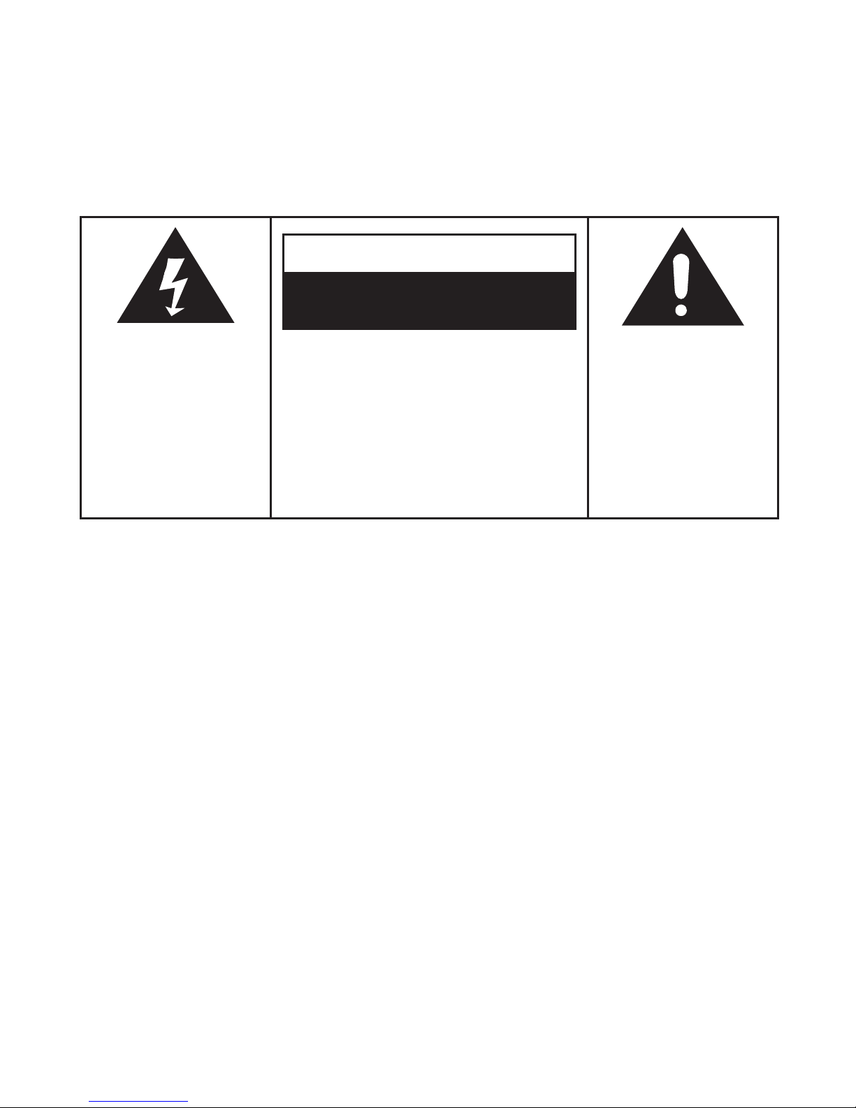
The lighting flash with
arrowhead symbol, within
an equilateral triangle, is
intended to alert user to
the presence of uninsulated
"dangerous voltage" within
the product's enclosure
that may be of sufficient
magnitude to constitute
risk of electric shock
to persons.
The exclamation point
within an equilateral
triangle is intended to
alert user to the
presence of important
operating and
maintenance (servicing)
instruction in the
literature accompanying
the appliance.
RISK OF ELECTRIC SHOCK
DO NOT OPEN
CAUTION
2
Page 4

Crosley Memory Master
This Manual
AC Adaptor
RCA to RCA Cable
Remote Controls
Lighting Remote Control
FM Antenna
BT Dock
Instructions in this manual describe the control
functions of the CR1206A.
Included in the package:
Control Locators
Unit Controls................................ 4
Remote Controls.......................... 5
Lighting remote control................ 6
Getting Started
Unpacking............................ ....... 7
Power Source.............................. 7
Antenna...................................... 7
Battery Back Up........................... 7
Basic Operation............................ 8
Setting The Clock......................... 8
Setting The Timer......................... 8
Sleep............................................ 9
Volume Control............................. 9
Mute............................................. 9
EQ................................................ 9
Radio Operation.......................... 10
CD Operation
CD Player
..................................... 11
Programming Tracks......
.............. 11
Erasing The Program................... 11
Using The Auxiliary Function
BT Dock....................................... 12
General
Optional External Speakers......
... 13
LED Lighting................................. 13
Auxiliary Inputs............................. 13
Troubleshooting Guide................. 13
Warranty....................................... 14
Thank you for purchasing the the Crosley Full Size
Tablet Jukebox (CR1206A). Before operating this
unit,please read this manual thoroughly and retain
it for future reference.
About This Manual
Welcome Table of Contents
3
Page 5
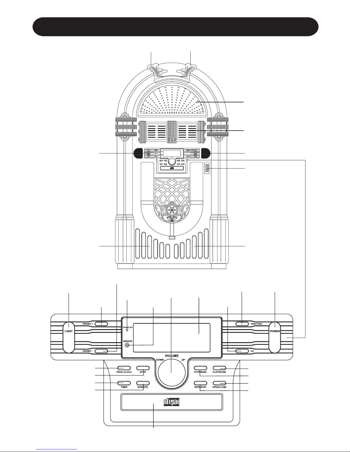
Control Locators
DOCK
VOLUME DOWN VOLUME UP
SPEAKER
TWEETER
LIGHT
PRESET +
PRESET –
STAND BY
INDICATOR
SENSOR
EQ
FUNCTION
PLAY/PAUSE
STOP/BAND
CD OPEN/CLOSE
REPEAT/ST
CD DOOR
DOWN / F.R.
TIMER
PROGRAM
VOLUME
UP/DOWN
KNOB
LCD
DISPLAY
POWER
UP/ F.F.
SPEAKER
TWEETER
WORD LED LIGHT
TUNNEL LED LIGHT
4
Page 6

BATTERY BACKUP
STAGE LIGHTING SWITCH
(RUN/STOP)
300ohm ANT.
EQ MUTE
OPEN/
CLOSE
PROG
MEM
012
3
4
5
678
TIMER
9
ID3
MONO
STEREO
REPEAT
CLOCK
RANDOM
BAND
PRESET
VOL
SLEEP
FUNC
POWER / STAND BY
EQ
PRESET +
PRESET -
PLAY / PAUSE
SKIP BACKWARD -
RANDOM
ID3
STOP / BAND
MONO/STEREO
TIMER
PROGRAM
SKIP FORWARD / +
VOLUME -
FUNCTION
VOLUME +
SLEEP
MUTE
CD OPEN / CLOSE
REPEAT
0-9
EXTERNAL
ANTENNA
EXTERNAL
SPEAKER JACK
SPEAKER
INT./EXT./MIX.
SWITCH
AUX IN JACK
DC IN JACK
Control Locators
5
Page 7

Control Locators
Run/Pause
BLUE (B)
DARK BLUE
BROWN
PINK
Increase BLUE
Decrease BLUE DIY (adjustment of colour by the user)
SMOOTH: 3-colour slow colour change -adjustable
FADE: 7-colour slow colour change -adjustable
STROBE: Colour fade out & fade in -adjustable
7-colour fast colour change
WHITE (W)
LED LIGHTING CONTROL FUNCTION
To control the LED lighting use the Infra-red Remote Control handset, which has 28 buttons, the function
of each button is as in the table below:
Brightness+ (8 in all)
RED (R)
ORANGE
DARK YELLOW
YELLOW
Increase RED
Decrease RED
Brightness- (8 in all)
GREEN (G)
LIGHT GREEN
BLUE
LIGHT BLUE
Increase GREEN
Decrease GREEN
(2) LIGHTING REMOTE CONTROL
DIY (adjustment of colour by the user)
3- colour slow colour change
7- colour fade change - adjustable
colour fade in & out - adjustable
7- colour fast colour change
Play/Pause
blue
dark blue
brown
Pink
Increase blue
Decrease blue
white
R G B W
FLASH
STROBE
FADE
SMOOTH
DIY
Brightness+(8 in all)
red
orange
dark yellow
yellow
Increase red
Decrease red
Brightness-(8 in all)
green
light green
Static cyan
light blue
Increase green
Decrease green
6
Page 8

1 Remove packing materials from unit.
Note: Save all packing materials
2 Remote control is located in the outside of the
Styrofoam packaging
3 Remove plastic bag covering radio and remote
control.
4 Untie antenna wire on back of radio.
5 Remove Styrofoam shipping material from
turntable.
6 Remove black tie-wrap from under the TONE
ARM .
7 Remove white protective needle cover by gently
pulling towards the front of the unit.
SET UP
1 Untie the wire on the AC power cord .
2 Press the MAIN POWER button on the back of
the unit to switch the main power on.
3 Press the POWER /
button on the front of
the unit to switch the unit to Standby mode.
4 Untie the FM antenna and allow it to hang down
in a straight line for optimum FM reception. If you
have trouble tuning in an FM station, move the
external FM antenna for best reception. Do not
connect FM antenna to outside antenna.
ANTENNA
Basic Operation
UNPACKING
POWER SOURCE
BATTERY BACK UP
Connect the AC power cord to the wall socket. This
system switches to Standby mode automatically and
LCD would shown as below
To switch the unit on, press POWER /
LCD
backlight will be turned on. STANDBY LED is turned
off and displayed as below.
The battery backup system to maintain your clock
and alarm settings during a power outage. In the
event of a power outage, the battery backup will
save your time and alarm settings until power is
restored. To utilize the battery backup, you must
install two AAA batteries. The battery backup will
not operate unless batteries are installed. To install
batteries, follow the instructions below.
1 Remove the Battery Compartment cover from
the back of the unit.
2 Install two new AAA batteries in the correct
position as shown inside the battery cover.
3 Reinstall the Battery Compartment cover.
NOTE:
Do not use different batteries
Do not mix old and new batteries
Antenna: for FM reception, the unit is provided
with a FM WIRE ANTENNA , move the wire until
the reception is clear and with no interferences.
For AM reception, the unit is provided with a
directional build-in ferrite antenna. Rotate the set
to find the position in which the best reception is
obtained. Do not connect the EXTERNAL FM
ANTENNA to any outside antenna.
7
Page 9

The unit can be used as an alarm clock, whereby
the selected source (CD, TUNER, USB, SD CARD
OR PHONO) to start playback at a preset time.
Make sure the clock is set before using the timer.
1 In the standby mode, press and hold TIMER
/
on the remote over 1 second, icon " " and
message” TURN ON” start flashing. Press TIMER
/
again on the remote to begin the “SYSTEM
POWER ON” timer setting.
2 Press FF /
or FB / repeatedly to set hours.
3 Press TIMER /
on the remote to enter minutes
setting mode.
4 Press FF /
or FB / repeatedly to set minutes.
5 Press TIMER /
on the remote again to begin
“SYSTEM POWER OFF” timer setting. Icon "
"
and message “TURN OFF” start flashing. Press
TIMER /
on the remote again to begin timer
setting.
6 Press FF /
or FB / repeatedly to set hours.
7 Press TIMER /
on the remote to enter minutes
setting mode.
8 Press FF /
or FB / repeatedly to set minutes.
9 Press TIMER /
on the remote again to begin
setting the source from wake up. Default at
TUNER mode. Message TUNER start flashing.
10 Press FUNCTION /
to select wake up source.
The unit will be waked up from last tuned station
if TUNER mode is selected.
11 Press TIMER / on the remote again to
complete timer on/off setting. Icon "
" will keep
display on LCD if timer is set.
Note: The wake up sound level will be increased
gently to preset volume level.
12 Press TIMER /
on the remote control to turn
on/off the timer. The icon "
" will be on/off
respectively.
AUX1AUX2
AUX1AUX2
BASIC OPERATION
Basic Operation
SETTING THE TIMER
SETTING THE CLOCK
After connecting the system to power supply, set
the clock first.
1 Press POWER /
to switch the unit to Standby
mode
- The display shows the time
- “0:00” flashes by default if you have not set the
clock
2 In the Standby mode, press and hold
PROGRAM /
over 1 second.
- The hours digit starts flashing.
3 Press the FF /
o FB / repeatedly to set
the hours.
4 Press PROGRAM /
again to confirm.
The minutes digit starts flashing
5 Hold down FF /
o FB / repeatedly to set
the minutes.
6 Press PROGRAM /
again to confirm.
The minutes digit stop flashing, the clock begins
to run.
7 Press PROGRAM /
to select between 12
and 24 hours, shown as below
Function select
1 Press FUNCTION /
to select among:
2 When the set is on, press POWER /
to
switch the unit off. LCD backlight will be turned
off and shown message“GOOD BYE” for 2
seconds, then the STANDBY LED is turned on.
Note: In the standby mode, the tone, sound
settings, tuner presets and the volume level (up
to a maximum volume level of 30) will be stored
in the unit’s memory.
8
Page 10

MUTE
SLEEP
Basic Operation
VOLUME CONTROL
EQ
You can set a certain period of time after which the
set will switch to standby.
On the remote control, press SLEEP /
repeatedly
to select the desired time period options (in minutes):
- Display shows in sequence: SLEEP 90, 80, 70,
60, 50, 40, 30, 20, 10
- Display shows the selected option briefly and
returns to its previous status.
To deactivate the sleep timer, press SLEEP /
again to “00 “ or Press POWER / to switch the
unit into standby mode.
Press EQ / on the remote control to select
desired EQ mode.
5 modes preset EQ:
Press VOLUME UP / / VOLUME DOWN /
on the remote control to adjust the volume.
You can temporarily switch off the sound without
switching off the unit.
1 Press MUTE /
on the remote control to switch
off the sound, playback continues without sound.
2 To switch on the sound , you can:
- press MUTE /
again;
- adjust the volume controls;
- change source
9
Page 11

RADIO OPERATION
Basic Operation
AM/FM Tuning
1 Press the FUNCTION /
to set the unit to
TUNER mode.
2 Press STOP/BAND /
repeatedly to select
your desired waveband. FM or AM
3 Auto Tuning – Press and hold FF /
or FB /
until frequency begins to scroll the radio
automatically tunes to a station with sufficient
reception. If a station in received in stereo, (ST)
is shown. Repeat step 3 if necessary until you
find the desired station.
4 Manual Tuning – Press FF /
or FB / briefly
and repeatedly until found a station.
Programming radio stations
You can store up to a total of 40 radio stations (FM
and AM) in the memory, manually or automatically
(Autostore)
1 Tune to your desired station
2 Press PROGRAM /
to activate programming,
icon “ MEMORY” and P01 will start flashing.
3 Press PRESET + /
or PRESET – / to
allocate a number from 1 to 20 stations.
4 Press PROGRAM /
to confirm, display shows
the preset number waveband and the frequency
of the preset station.
5 Repeat steps 1-4 to store other stations to listen
to a preset station. Press PRESET + /
or
PRESET – /
once or more until the desired
preset station in displayed.
To listen to a preset station
Press PRESET + /
or PRESET – / once or
more until the desired preset station in displayed.
Automatic programming radio stations Automatic
programming will station preset 1, from this preset
number upwards, former programmed tuner stations
will be erased.
1 Press and hold PROGRAM /
button until Auto
appears
- Icon “ memory” will start flashing
- Available stations are programmed
- After all stations are stored, the last preset station
will then be played
10
Page 12

CD Operation
PROGRAMMING TRACKS
CD PLAYER
Playing a CD
1 Press the FUNCTION /
to set the unit to CD
mode.
2 Press CD OPEN / CLOSE /
to open the CD
compartment
3 Insert a disc with the printed side facing up.
Press CD OPEN / CLOSE /
. again to close
the compartment, READ is displayed as the CD
player scans the contents of a disc.
4 Track no. 1 will be playback automatically after
finish the reading CD disc contents.
5 Press FF /
or FB / once or repeatedly
until the desired track number appears in display.
6 Press STOP/BAND /
to stop playback.
CD-MP3 disc playback
1 Insert CD-MP3 format disc. Press CD OPEN /
CLOSE /
again to close the compartment.
READ is displayed as the CD player scans the
contents of a disc.
2 Track no. 1 of root folder (Folder 1) will be playback
automatically after finish reading CD-MP3 disc
contents.
3 Press FF /
or FB / once or repeatedly
until the desired track number appears in display.
4 Press PRESET + /
or PRESET – / to select
desired album.
5 Press STOP/BAND /
to stop playback.
You may store up to 20 tracks in the desired
sequence.
1 In the stop position, press PROGRAM /
to
start programming. Icon “MEMORY” and P0-01
start flashing.
2 Press FF /
or FB / once or repeatedly until
the desired track number appears in the display.
For MP3:
press PRESET + /
or PRESET – / to select
the desired album.
3 Press PROGRAM /
to confirm, display shown
stored track no. and next store position.
4 Repeat step 2-3 to select and store all desired
tracks. FULL is displayed if you attempt to program
more than 20 tracks
5. Press PLAY/PAUSE /
to play the program.
You can erase the contents of the memory by:
- once if in stop position, twice during playback;
- Press POWER /
- Select another sound source
- Open the CD door
ERASING THE PROGRAM
11
Page 13

LED INDICATOR RESET BUTTON
USING THE AUXILIARY FUNCTION
BT Dock
The function select
1 Press
POWER /
button to no the unit.
2 Press the function switch to the AUX1 mode.
3 The Bluetooth receiver of the LED indicator will
be on. that is standBy.
Using Bluetooth
Bluetooth enables a wireless connection between
a device (such as a smart phone) and the Jukebox,
enabling the user to play and control tracks direct
from their Bluetooth enabled device.
Firstly, the user must ensure that they have a
compatible Bluetooth enabled device (with media
playing capabilities) such as an Android
® Smartphone
or Apple iPhone
® with Bluetooth capability. Secondly,
the user must ensure that they have loaded
compatible audio files on to the device in order to
play through the Jukebox. Once these have both
been confirmed, the user can connect their device
to the Jukebox.
The Bluetooth receiver is packed separately to the
main Jukebox housing. To set up the Bluetooth
receiver and connect to your Bluetooth enabled
device follow these steps:
1 Locate the Bluetooth receiver and remove from
packaging.
2 Place the receiver into the Bluetooth receiver
dock which is located on the front panel of the
Jukebox.
(please refer to the diagram on page 4).
3. Press the RESET button in order to power ON.
The LED indicator will illuminate to indicate that
it has successfully turned on.
4 The LED indicator will flash indicating that it is
searching for a nearby Bluetooth enabled device
to connect too.
5 On your Bluetooth enabled device, search for
nearby devices. When your device finds BT-
DOCK connect to this device. There should be
no requirement for a PIN.
6 When the Jukebox has connected to your
Bluetooth enabled device successfully, your
device will indicate that they are connected and
the indicator light on the Bluetooth
Dock in the Jukebox will stop flashing and
continuously illuminate.
12
Page 14

Auxiliary Inputs
There is no power
1 Make sure radio is plugged in correctly.
2 Look at the STAND BY INDICATOR and check
to see if it is red.
3 If the red light is on, press the POWER /
to
turn the unit on.
There is no sound
1 Make sure the mute function is turned off.
2 Check that the volume is turned up by pressing
VOLUME UP /
on the remote.
Note: Volume range on some units start at level
15 and ends at level 40.
3. Make sure INT./EXT. switch on back of radio is
switched to INT. (Unless you are using external
speakers, in which case it should be on EXT. )
4 Check to make sure power is turned on.
CD does not play
1 Check to make sure CD is inserted correctly
(label side facing up).
2 Check to see that surface of CD is clean.
3 Make sure function switch is set to CD mode.
Remote not working
1 Replace battery.
2 Be sure to point the remote towards remote
sensor when operating.
3 Remove obstacles in the path of the remote and
radio so the remote signal has a straight path
to the radio.
General
TROUBLESHOOTING
1 With your new radio, you have the option of
adding external speakers.
2 The speaker jacks for external speakers are
located on the back of the radio. Along with the
speaker jacks is a switch labeled Int./Ext.
When using external speakers, this switch must
be switched to the EXT. position. Doing this turns
off the internal speakers in the radio and redirects
the power to the external speakers.
3 If you decide not to use the external speakers,
be sure the switch is switch to INT.
OPTIONAL EXTERNAL SPEAKERS
LED LIGHTING
The 7-colour changing LED lights in the front tubes
are controlled by the LIGHTING SWITCH
(RELEASE/HOLD) on the rear of the unit.
Using the Aux Input allows you to hook up additional
external audio components and listen to them through
your unit. Any component with an audio output such
as a Tuner, can be connected by using the correct
cables . This unit uses standard RCA cables. Simply
plug the red and white connectors on one end of
the cable to the red and white RCA In jacks on the
back of your unit. The other end of the cable will
plug into the Audio Output jack on the external
component. For more information on hooking up the
external component, see the owner's manual for
that component.
13
Page 15

Crosley Radio, Inc. warrants the product to be free from defects in material and
workmanship under normal use for a period of one year from the original date of
purchase. This warranty is not transferable. If the product is determined to be defective
during the warranty period, the unit will be repaired or replaced at Crosley Radio’s sole
discretion. This warranty covers manufacturing defects and normal consumer use and
does NOT cover damage or failure as a result of abuse, accident, alterations, misuse,
neglect, abnormal wear and tear, inadequate maintenance, commercial or unreasonable
use, damage caused by power surges, mishandling, accident, acts of God or attempted
repair by an unauthorized service agent. Also not covered are cosmetic damages,
cords and antennas.
Should this product fail to function in a satisfactory manner, it is best to first contact
our technical support team for assistance to ensure it is being operated properly.
Tech Support and Product Questions
CALL TOLL FREE: 1.888.CROSLEY
(1.888.276.7539)
If it is indeed determined that the unit is no longer operational, please contact the
retailer from which it was purchased. In many cases, your retailer will be able to provide
a replacement unit at no charge within the scope of their return policy. If the retail return
period has expired, please contact Crosley Radio directly to participate in the one year
protection program.
Crosley 1 Year Warranty Program
CALL TOLL FREE: 1.800.926.7801
You will need to contact our offices M-F 8am-5pm EST to obtain an RA (Return
Authorization) Number. You will be instructed to send the unit (at your cost) to our
offices in its original packaging (or reasonable substitute to prevent damage.) You will
need to clearly mark your RA number on the outside packaging and include the original
sales receipt (or a copy) indicating date of purchase, amount paid, and place of
purchase. You will also need to include your full name, shipping address and daytime
contact number. You will be instructed to include a check or money order for any
applicable return shipping and handling fees. A Crosley advisor will confirm the fees
associated with your product's shipping size/weight. Returned products will not be
shipped to PO Boxes. Crosley Radio will not be responsible for delays or unprocessed
claims resulting from a purchaser's failure to provide any or all of the necessary
information.
There are no express warranties except as listed above.
The purchaser's bill of sale is the only proof of warranty entitlement.
This warranty gives the purchaser specified legal rights in addition to any rights which may vary
from state to state.
In accordance with the "Moss-Magnuson Warranty Act" of July 10, 1975, this is termed a "limited
warranty" which in no way compromises Crosley Radio's high standards of quality and workmanship.
LIMITED MANUFACTURERS WARRANTY
14
Page 16

910-122021-0010-200
 Loading...