

Crosley CLCE900FW2, CLCG900FW2, CLCG900FW3, GLEH1642FS2, GLGH1642FS1 Installation Guide
...Page 1
Installation Instructions
Full Size Laundry Center Gas & Electric
instrucciones para la instalaci6n
Centro de lavanderia a gas y electrica
!
\
www.frigidaire.com P/N134889400A (0804)
Page 2

CONTENTS
SUBJECT PAGE
Pre-lnstallation Requirements ....................................................................................................................................... 3
Electrical Requirements ................................................................................................................................................ 3
Water Supply Requirements ............................................................................................................................................ 3
Drain Requirements ...................................................................................................................................................... 3
Exhaust System Requirements ................................................................................................................................... 4-5
Gas Supply Requirements .............................................................................................................................................. 5
Location .................................................................................................................................................................... 5
Rough-In Dimensions ................................................................................................................................................. 6
Mobile Home Installation ............................................................................................................................................. 7
Unpacking .................................................................................................................................................................. 7
Electrical Installation .................................................................................................................................................... 8
Grounding Requirements .............................................................................................................................................. 8
3 & 4-Wire Connections ........................................................................................................................................... 8-9
Installation ............................................................................................................................................................. 9-10
ReplacementParts ..................................................................................................................................................... 10
Espahol ............................................................................................................................................................... 11-20
Laundry Center Safety
Before beginning installation, carefully read these instructions. Thiswill simplify the installation
and ensure the laundry center is installed correctly and safely. Leave these instructions near the
laundry center after installation for future reference.
NOTE: The electrical service to the laundry center must conform with local codes and ordinances and the latest edition of the
National Electrical Code, ANSI/NFPA 70, or in Canada, the Canadian Electrical Code, CSA C22. 1
NOTE: The gas serviceto the laundry center must conform with local codes and ordinances and the latest edition of the National
Fuel GasCode ANSI Z223. 1/NFPA54, or in Canada, the Canadian Natural Gasand Propane Installation Code, CSAB149.1.
NOTE: The laundry center isdesigned under ANSI Z21.5.1 or ANSI/UL 2158- CAN/CSA C22.2 No. 112 (latest edition) for HOME
USEonly. This laundry center is not recommended for commercial applications such as restaurants or beauty salons, etc.
Your safety and the safety of others is very important.
We have provided many important safety messagesin the Use& Care Guide, Operating Instructions, Installation Instructions and
on your appliance. Always read and obey all safety messages.
]-his isthe safety alert symbol. This symbol alerts you to hazards that can kill or hurt you or others. All safety messages
will be preceded by the safety alert symbol and the word "DANGER" or "WARNING". These words mean:
You will be killed or seriously injured if you don't follow instructions.
You can be killed or seriously injured ff you don't foflow instructions.
All safety messages will identify the hazard, tell you how to reduce the chance of injury, and tell you what can happen if the
instructions are not followed.
Foryour safety the information in this manual must be followed to minimize the risk of fire or explosion or to prevent
property damage, personal injury or lossof life.
- Do not store or use gasoline or other flammable vapors and liquid in the vicinity of this or any other appliance.
- WHAT TO DO IF YOU SMELL GAS
• Do not try to light any appliance.
• Do not touch any electrical switch; do not use any phone in your building.
• Clear the room, building or area of all occupants.
Immediately call your gas supplier from a neighbor's phone.
• Follow the gas supplier's instructions.
• if you cannot reach your gas supplier, call the fire department.
Installationand service must be preformed by a qualified installer, service agency or the gas supplier.
Page 3
PRE-INSTALLATION REQUIREMENTS
Tools and Materials Required for Installation:
1. Phillips head screwdriver
2. Channel-lock adjustable pliers
3. Carpenter's level
4. Flat or straight blade screwdriver
5. Duct tape
6. Rigid or flexible metal 4 inch (10.16 cm) duct
7.Vent hood
8. Pipe thread sealer (Gas)
9.1/4 inch socket w/ratchet
10.3/8 inch socket w/ratchet
11.3/8 inch open end wrench
12.7/16 inch open end wrench
13.9/16 inch open end wrench
ELECTRICAL REQUIREMENTS
ELECTRICLaundry Center
CIRCUIT- Individual 30 amp. branch circuit fused with 30
amp. time delay fuses or circuit breakers.
Use separately fused circuits for washers and dryers, and DO
NOToperate a washer and a dryer on the same circuit.
POWER SUPPLY - 3 wire or 4-wire, 240 volt, single phase, 60
Hz, Alternating Current.
POWER SUPPLYCORD KIT- 3 wire -the laundry center MUST
employ a 3-conductor power supply cord NEMA 10-30 type SRDT
rated at 240 volt AC minimum, 30 amp., with 3 open end spade
lug connectors with upturned ends or closed loop connectors
and marked for use with clothes dryers. See ELECTRICAL
CONNECTIONSFORA 3-WIRE SYSTEM.
4 wire - The laundry center MUSTemploy a4-conductor power
supply cord NEMA 14-30 type SRDTor ST (as required) rated at
240 volt AC minimum, 30 amp., with 4 open end spade lug
connectors with upturned ends or closed loop connectors and
marked for use with clothes dryers. See ELECTRICAL
CONNECTIONSFORA 4-WIRE SYSTEM.
(Canada-4-wire power supply cord is installed on laundry center.)
WARNING- Risk of Shock. Appliance grounded to neutral
conductor through a link. Grounding through the neutral link is
prohibited for (1) New branch circuit installations (2) mobile
homes; (3) recreational vehicles; and (4) areaswhere local codes
do not permit grounding through the neutral, (1) disconnect the
link from the neutral, (2) use grounding terminal or lead to
ground appliance in accordance with localcodes and (3) connect
neutral terminal or lead to branch circuit neutral in usual manner
(if the appliance is to be connected by means of a cord kit, use
4-conductor cord for this purpose). USECOPPERCONDUCTOR
ONLY.
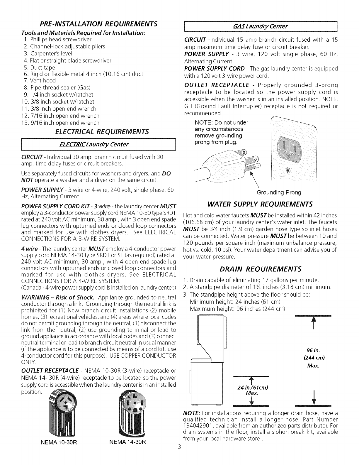
OUTLET RECEPTACLE- NEMA 10-30R (3-wire) receptacle or
NEMA 14- 30R (4-wire) receptacle to be located so the power
supply cord isaccessiblewhen the laundry center isin an installed
position.
i
CIRCUIT-Individual 15 amp branch circuit fused with a 15
amp maximum time delay fuse or circuit breaker.
POWER SUPPLY - 3 wire, 120 volt single phase, 60 Hz,
Alternating Current.
POWER SUPPLY CORD - The gas laundry center is equipped
with a 120 volt 3-wire power cord.
OUTLET RECEPTACLE - Properly grounded 3-prong
receptacle to be located so the power supply cord is
accessible when the washer is in an installed position. NOTE:
GFI (Ground Fault Interrupter) receptacle is not required or
recommended.
NOTE: Do not under
any circumstances
remove grounding
i
prong from plug.
GASLaundry Center
\
Grounding Prong
WATER SUPPLY REQUIREMENTS
Hot and cold water faucets MUSTbe installed within 42 inches
(106.68 cm) of your laundry center's water inlet. The faucets
MUST be 3/4 inch (1.9 cm) garden hose type so inlet hoses
can be connected. Water pressure MUSTbe between 10 and
120 pounds per square inch (maximum unbalance pressure,
hot vs. cold, 10 psi). Your water department can advise you of
your water pressure.
DRAIN REQUIREMENTS
1. Drain capable of eliminating 17 gallons per minute.
2. A standpipe diameter of 11/4inches (3.18 cm) minimum.
3. The standpipe height above the floor should be:
Minimum heic ht: 24 inches (61 cm)
Maximum heicht: 96 inches (244 cm)
96 in.
(244 cm)
Max.
t
24 in.(61cm)
]
NEMA 10-30R
NEMA 14-30R
NOTE: For installations requiring a longer drain hose, have a
qualified technician install a longer hose, Part Number
134042901, available from an authorized parts distributor. For
drain systems in the floor, install a siphon break kit, available
from your local hardware store.
Page 4
EXHAUSTSYSTEMREQUIREMENTS
Useonly4 inch(10.16cm)diameter(minimum)
flexible metal duct and approved vent hood which has a
swing-out damper(s) that opens when the dryer is in
operation. When the dryer stops, the damper(s)
automatically doses to prevent drafts and the entrance
of insects and rodents. To avoid restricting the outlet,
maintain a minimum of 12 inches (38.5 cm) clearance
between the vent hood and the ground or any other
obstruction.
Thefollowing are specific requirements for proper
and safe operation of your laundry center. Failureto follow these
instructions can create excessive drying times and fire hazards.
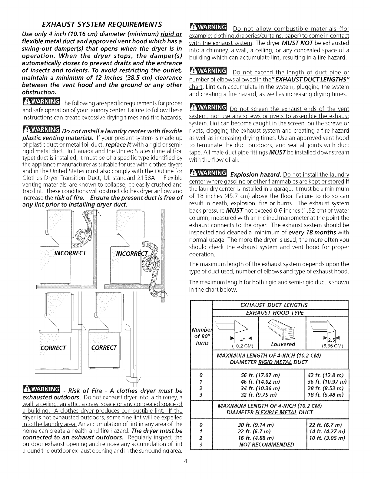
Do not install a laundry center with flexible
plastic venting materials. Ifyour present system is made up
of plastic duct or metal foil duct, replace itwith a rigid or semi-
rigid metal duct. InCanada and the United States if metal (foil
type) duct is installed, it must be of a specific type identified by
the appliance manufacturer assuitable for usewith clothes dryers
and in the United States must also comply with the Outline for
Clothes Dryer Transition Duct, UL standard 2158A. Flexible
venting materials are known to collapse, be easily crushed and
trap lint. These conditions will obstruct clothes dryer airflow and
increase the risk of fire. Ensure the present duct is free of
any lint prior to installing dryer duct.
Do not allow combustible materials (for
example: clothing,draperies/curtains paper) to come in contact
with the exhaust system. The dryer MUST NOT be exhausted
into a chimney, a wall, a ceiling, or any concealed space of a
building which can accumulate lint, resulting in a fire hazard.
Do not exceed the length of duct pipe or
number of elbows allowed in the" EXHAUST DUCT LENGTHS"
chart. Lint can accumulate in the system, plugging the system
and creating a fire hazard, aswell as increasing drying times.
Do not screen the exhaust ends of the vent
system, nor use any screws or rivets to assemble the exhaust
system. Lint can become caught in the screen, on the screws or
rivets, clogging the exhaust system and creating a fire hazard
aswell as increasing drying times. Use an approved vent hood
to terminate the duct outdoors, and seal all joints with duct
tape. All male duct pipe fittings MUST be installed downstream
with the flow of air.
Explosion hazard. Do not install the laundry
center where gasoline or other flammables are kept or stored.If
the laundry center isinstalled in a garage, it must be a minimum
of 18 inches (45.7 cm) above the floor. Failure to do so can
result in death, explosion, fire or burns. The exhaust system
back pressure MUSTnot exceed 0.6 inches (1.52 cm) of water
column, measured with an inclined manometer at the point the
exhaust connects to the dryer. The exhaust system should be
inspected and cleaned a minimum of every 18 months with
normal usage. The more the dryer is used, the more often you
should check the exhaust system and vent hood for proper
operation.
The maximum length of the exhaust system depends upon the
type of duct used, number of elbows and type of exhaust hood.
- Risk of Fire - A clothes dryer must be
exhausted outdoors. Do not exhaust dryer into a chimney, a
wall, a ceiling, an attic, a crawl space or any concealed space of
a building A clothes dryer produces combustible lint. If the
dryer is not exhausted outdoors some fine lint will be expelled
into the laundry area. An accumulation of lint in any area of the
home can create a health and fire hazard. The dryer must be
connected to an exhaust outdoors. Regularly inspect the
outdoor exhaust opening and remove any accumulation of lint
around the outdoor exhaust opening and in the surrounding area.
The maximum length for both rigid and semi-rigid duct isshown
in the chart below.
EXHAUST DUCT LENGTHS
EXHAUST HOOD TYPE
Number
of 90 °
Turns
0
1
2
3
0
1
2
3
(10.2 CM)
MAXIMUM LENGTH OF 4-INCH (10.2 CM)
DIAMETER RIGID METAL DUCT
56 ft. (17.07 m)
46 ft. (14.02 m)
34 ft. (10.36 m)
32ft. (9.75m)
MAXIMUM LENGTH OF 4-INCH (10.2 CM)
DIAMETER FLEXIBLE METAL DUCT
30 ft. (9.f4 m)
22 ft. (6.7 m)
16 ft. (4.88 m)
NOT RECOMMENDED
Louvered
(6.35 CM)
42 ft. (12.8 m)
36 ft. (10.97 m)
28 ft. (8.53 m)
18 ft. (5.48 m)
22 ft. (6.7 m)
14 ft. (4.27 m)
10 ft. (3.05 m)
Page 5

The laundry center may be exhausted four (4) ways with rear
flush installation:
1. Straight back
2. Down (8 inch [20.32 cm] length of 4 inch [10.16 cm] rigid
duct and 1 elbow down)
3. Left (8 inch [20.32 cm] length of 4 inch [10.16 cm] rigid
duct, 1 elbow down and 1 elbow left)
4. Right (8 inch [20.32 cm] length of 4 inch [10.16 cm] rigid
duct, 1 elbow down and 1 elbow right)
Although vertical orientation of the exhaust systemisacceptable,
certain extenuating circumstances could affect the performance
of the dryer:
• Only the rigid metal duct
work should be used.
• Venting vertical through
a roof may expose the
exhaust system to down
drafts causing an
increase in vent
restriction.
• Running the exhaust
systemthrough an
uninsulated area may
cause condensation and
faster accumulation of
lint.
• Compression orcrimping
of the exhaust system
will cause an increase in
vent restriction.
To exhaust up, add an 11 inch (27.94 cm) length of standard 4
inch (10.16 cm) diameter duct and a 90° elbow. The unit will
be positioned about 41/2inches (11.43 cm) away from the wall
(flush to wall exhausting may be done by going below the dryer
then sideways).
An exhaust hood positioned to line up with the dryer exhaust
can be installed directly through the outside wall. Toexhaust to
the side or down, add an 8 inch (20.32 cm) length of standard 4
inch (10.16 cm) diameter duct and a 90° elbow.
GAS SUPPLY REQUIREMENTS
1.Installation MUST conform with local codes, or in the absence
of local codes, with the National FuelGasCode, ANSI Z223.1
(latest edition) or in Canada, the current AN/CGA B149.
2.The gas supply line should be of 1/2 inch (1.27 cm) pipe.
3.If codes allow, flexible metal tubing may be used to connect
your dryer to the gas supply line. The tubing MUST be
constructed of stainless steel or plastic-coated brass.
4.The gas supply line MUSThave an individual shutoff valve.
5.A 1/8 inch (0.32 cm) N. RT. plugged tapping, accessible for
test gage connection, MUST be installed immediately
upstream of the gas supply connection to the dryer.
6.The dryer and its individual shutoff valve MUST be
disconnected from the gas supply piping system during any
pressure testing of the gas supply piping system at test
pressures equal to or less than 1/2 psig (3.45 kPa).
7.Thedryer MUST be isolated from the gassupply piping system
by closing its individual manual shutoff valve during any
pressuretesting of the gassupply piping system at test pressures
equal to or lessthan 1/2 psig (3.45 kPa).
LOCATION OF YOUR LAUNDRY CENTER
DO NOT INSTALL YOUR LAUNDRY CENTER:
1. In an area exposed to dripping water or outside weather conditions.
2. In an area where it will come in contact with curtains or drapes.
3. On carpet. Floor MUSTbe solid with a maximum slope of 1 inch (2.54 cm).
4. On a pedestal. Excessivevibration can occur.
INSTALLATION IN RECESSOR CLOSET
1. A laundry center installed in a bedroom, bathroom, recessor closet, MUSTbe exhausted outdoors.
2. No other fuel burning appliance shall be installed in the same closet as the Gas laundry center.
3. Your laundry center needs the space around it for proper ventilation.
DO NOT INSTALL YOUR LAUNDRY CENTERIN A CLOSET WITH A SOLID DOOR.
4. A minimum of 120 square inches (774.2 square cm) of opening, equally divided at the top and bottom of the door, is
required. Air openings are required to be unobstructed when a door is installed. A Iouvered door with equivalent air openings
for the full length of the door is acceptable.
5. The following illustrations show minimum clearance dimensions
installation, oIN.
(oCM)_
--60 SQ. IN.
(387.1 SQ. CM)
and air openings for proper operation in a recess or closet
0 IN. 1IN. ', ', ',', 0 IN.
cM) (zs4cWi,, cM)
#. .
Closet Door
-- 60 SQ. IN.
(387.1 SQ. CM)
5
Page 6

ROUGH-IN DIMENSIONS
_J
f
16 1AIN,
(41,27 CM)
75_ IN.
(191.14 CM.)
(134.62 CM.)
_r
l&
53 IN. --/r:-
31% I^
(8o.65 c_
]2Y21N,J._ _ 9S/81N,
(3] ,75 CM} I (23,_
VENT--/1-"_
3 :Y4IN, __._d
(9,52CM)
DRAIN OUTLET -
(REAR) --/
27 IN,
(68,58CM)
5 1AIN, _' T
_--(] 3,33 CM)
40Y2IN.
(102.87 CM.)
GASSUPPLY
PIPE(REAR)
/
42_ IN.
(107.32 CM.)
36 IN.
(91.44 CM.)
29% IN.
(75.57CM.)
J
(7.62_M.)
1 7/8 IN,
(4,76 CM)
31/8 IN.
(7.94 CM.)
3 IN.
Page 7

MOBILE HOME INSTALLATION
1. Dryer MUST be exhausted outside (outdoors,
not beneath the mobile home) using metal
ducting that will not support combustion. Metal
ducting must be 4 inches (10.16 cm)in
diameter with no obstructions. Rigid metal duct
is preferred.
2. If dryer is exhausted through the floor and area
beneath the mobile home is enclosed, the
exhaust system MUST terminate outside the
enclosure with the termination securelyfastened
to the mobile home structure.
X
iilil
i I,q,!,!,!,!,,! i,,_@iw! _ , ,
3. Refer to page 3 for other important venting
requirements.
4. When installing a gas dryer into a mobile home,
a provision must be made for outside make up
air. This provision is to be not lessthan twice
the area of thedryer exhaust outlet.
5. Installation MUST conform to current
Manufactured Home Construction & Safety
Standard (which is a Federal Regulation Title
24 CFR-Part 32-80) or when such standard is
not applicable, with American National Standard
for Mobile Homes. In Canada, the CSA Z240 is
applicable.
The laundry center is designed
under ANSI Z 21.5.1 for
HOME USE only.
UNPACKING
1. Using the four shipping carton corner posts (two on each side), carefully
lay the laundry center on its left side and remove the foam shipping
base.
_ Excessive weight. Use two or more people to
-- move Laundry Center.
CARTON CORNER POSTS
FOAM
SHIPPING
PAD
,
Return laundrycenter to an upright position.
3.
Removethe following from
the back side of the
washer:
4 bolts,
4 yellow plastic spacers,
3 metal "P" clamps.
,
Remove the service panel
from the front of the
washer.
,
Remove the 4 nuts and 6
large washers that attach
the 2 yellow shipping
braces to the drum and
the base. Lift up on the
drum and remove the
braces (a yellow ribbon
surrounds the items to be
removed).
,
Remove the large
styrofoam block located
under the drum. Lift up on
®
®
the drum, tilt the base of
the foam block inwards
toward the rear of the
washer until free, then pull
it out.
,
Remove and discard the
yellow ribbon and label
from the front of the
washer.
,
Replace the service panel
and screws.
9.
Carefully move the laundry
center to within 4 feet
(1.22m) of the final location
to begin the installation.
NOTE: If the laundry
f_
center is to be _ o
transported at a later
date, the shipping
support hardware must
be reinstalled toprevent
shipping damage.
Page 8
ELECTRICAL INSTALLATION
ALL ELECTRICLaundry Centers
The following are spedfic requirements
for proper and safe electrical installation of your laundry
center. Failure to follow these instructions can create an
electrical shock and/or a fire hazard.
_This appliance MUST be properly grounded.
Electrical shock can result if the laundry center isnot properly
grounded. Follow the instructions in this manual for proper
grounding.
Do not use an extension cord with this
laundry center. Some extension cords are not designed to
withstand the amounts of electrical current this laundry center
utilizes and can melt, creating electrical shock and/or fire
hazard. Locate the laundry center within reach of the receptacle
for the length power cord to be purchased, allowing some slack
in the cord. Refer to the pre-installation requirements in this
manual for the proper power cord to be purchased.
_ A U.L. approved strain relief must be
installed onto power cord. If the strain relief is not attached,
the cord can be pulled out of the laundry center and can be
cut by any movement of the cord, resulting in electrical shock.
Do nott use an aluminum wired receptacle
with a copper Wired power cord and plug (or vice versa). A
chemical reaction occurs between copper and aluminum and
can cause electrical shorts. The proper wiring and
receptacle is a copper wired power cord with a copper
wired receptacle OR aluminum wired power cord with
an aluminum wired receptade.
NOTE: Laundry centers operating on a 208 volt power supply
will have longer drying times than laundry centers operating on
a 240 volt power supply.
GROUNDING REQ UIREMENTS
Non-Canadian ELECTRICLaundry Center ]
Improper connection of the equipment
grounding conductor can result in a risk of electrical shock.
Check with a licensed electrician if you are in doubt as to
whether the appliance is properly grounded.
For a grounded cord-connected laundry center:
1. The laundry center MUST be grounded. In the event of
malfunction or breakdown, grounding will reduce the risk of
electrical shock by a path of least resistance for electrical
current.
2. If your laundry center isequipped with a power supply cord
having an equipment-grounding conductor and a grounding
plug, the plug MUSTbe plugged into an appropriate, copper
wired receptacle that is properly installed and grounded in
accordance with all local codes and ordinances. If in doubt,
call a licensed electrician.
For a permanently connected laundry center:
The laundry center MUSTbe connected to a grounded metal,
permanent wiring system;or anequipment grounding con-ductor
MUSTbe run with the circuit conductors and connected to the
equipment-grounding terminal or lead on the appliance.
[
The laundry center is equipped with a three-prong (grounding)
plug for your protection against shock hazard and should be
plugged directly into a properly grounded three-prong receptacle.
Do not cut or remove thegrounding prong from the plug.
_lmproper connection of the equipment
grounding conductor can result in a risk of electrical shock.
Check with a licensed electrician if you are in doubt as to
whether the appliance is properly grounded.
For a grounded cord connected laundry center:
1. The laundry center MUST be grounded. In the event of
malfunction or breakdown, grounding will reduce the risk of
electrical shock by providing a path of least resistance for
the electrical current.
2. Since your laundry center is equipped with a power supply
cord having an equipment-grounding conductor and a
grounding plug, the plug MUST be plugged into an
appropriate outlet that isproperly installed and grounded
in accordance with all codes and ordinances. If in doubt,
call a licensed electrician.
[
NON-CANAD/AN ELECTR/CLaundry Center
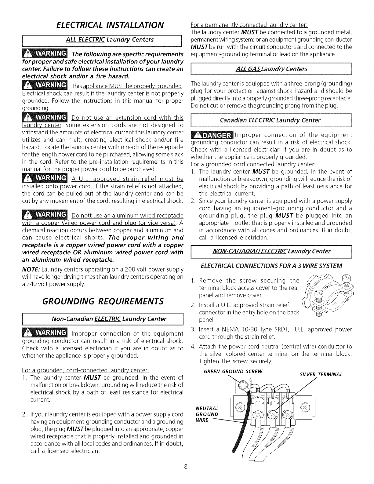
ELECTRICAL CONNECTIONS FOR A 3 WIRESYSTEM
,
Remove the screw securing the
terminal block access cover to the rear
panel and remove cover.
,
Install a U.L. approved strain relief
connector in the entry hole on the back
panel.
,
Insert a NEMA 10-30 Type SRDT, U.L. approved power
cord through the strain relief.
,
Attach the power cord neutral (central wire) conductor to
the silver colored center terminal on the terminal block.
Tighten the screw securely.
GREEN GROUND SCREW
NEUTRAL
GROUND
WIRE
ALL 6AS Laundry Centers
Canadian ELECTRIC Laundry Center }
SILVER TERMINAL
}
J
Page 9

5. Attach the remaining two power cord outer conductors to
the outer brass colored terminals on the terminal block.
Tighten both screw securely.
6. Tighten the screws securing the cord restraint against the
power cord.
7. Reinstall the terminal access cover.
[ NON-CANAD/ANELECTR/CLaundryCenter ]
ELECTRICALCONNECTIONS FORA 4-WIRE SYSTEM
1. Remove the screw securing the
terminal block accesscover to the rear
panel and remove cover.
2. Install a U.L. approved strain relief
connector in the entry hole on the
back panel.
INSTALLATION
Leve/ing the Laundry Center
Excessive noise and vibration can be prevented by properly
leveling the washer.
1. With the laundry center in it's final position, place a level
ontop of the laundry center. Adjust the leveling legs so the
laundry center is level front-to-rear and side-to-side, and
stable corner-to-corner.
3. Remove the ground wire from the green ground screw
located above the termial block.
GREEN GROUND GREEN
SCREW CONDUCTOR
GROUND
WIRE
RED /
POWER CORD
SILVER TERMINAL
TERMINAL BLOCK
WHITE
STRAIN '
RELIEF
4. Insert a NEMA 14-30 Type STor SRDT,U.L. approved power
cord through the strain relief.
5. Attach the green power cord ground wire to the cabinet
with the green ground screw.
6. Attach the white (neutral) wire from the power cord and the
ground wire from the appliance harness to the silver-colored
center terminal on the terminal block. Tighten the screw
securely.
7. Attach the red and black wires from the power cord to the
outer brass-colored terminals on the terminal block. Tighten
both screws securely.
8. Tighten the screws securing the cord restraint firmly against
the power cord.
9. Reinstall the terminal block access cover.
Pressdown on alternate corners and sides and feel for the
slightest movement. Adjust the appropriate leg so the
washer is SOLID on the floor on ALL four legs. Keep the
leveling leg extension at a minimum for best performance of
the laundry center.
Washer Connections
.
Run some water from the hot and cold faucets to flush the
water lines and remove particles that might clog up the water
valve screens.
Check inlet hosesto ensure the rubber washers are installed
.
in each end.
3.
Carefully connect the inlet hoses to the water valve (on the
left sideof the washer cabinet), tighten by hand, then tighten
another 2/3 turn with pliers.
DO NOT CROSS THREAD OR
__.=_w__ OVERTIGHTEN THESE CONNECTIONS.
4. Determine which water faucet is the HOTwater faucet and
carefully connect the bottom inlet hose to the HOT water
faucet, tighten by hand, then tighten another 2/3 turn with
pliers. Carefully connect the top inlet hose to the COLD
water faucet, tighten by hand, then tighten another 2/3 turn
with pliers.
w . a . DO NOT CROSS THREAD OR
__,,7_,_,,__ OVERTIGHTEN THESE CONNECTIONS.
Turn the water on and check for leaks at both connections.
GAS CONNECTION (Gas laundry centers only)
.
Remove the shipping cap from gas pipe at the rear of the
dryer.
NOTE: DO NOT connect the laundry center to L.P.gas
service without converting the gas valve. An L.R conversion
kit must be installed by a qualified gas technician.
.
Connect a 1/2 inch (1.27 cm) I.D. semi-rigid or approved
pipe from the gas supply line to the 3/8 inch (0.96 cm) pipe
located on the back of the dryer. Use a 1/2 inch (1.27 cm) to
3/8 inch (0.96 cm) reducer for the connection. Apply an
approved thread sealerthat isresistant to the corrosive action
of liquefied gases on all pipe connections.
Page 10

3. Opentheshutoffvalveinthegassupplyline.
4. Testallconnectionsbybrushingonasoapywatersolution.
NEVER TEST FOR GAS LEAKS WITH AN OPEN FLAME.
Drain Hose installation
1. Form a " U " shape on the end of the drain hose with the
hose pointed toward the drain. Place the formed end in a
laundry tub or a standpipe and secure with a cable tie
provided inthe enclosure package. An air gap must be around
the drain hose. WATER WILL SIPHON FROM THE
WASHER IF THE ABOVE INSTRUCTIONS ARE NOT
FOLLOWED.
3. Turn on the power at a circuit breaker/fuse box.
_ Before operating the dryer, make sure the
dryer area isclear and free from combustible materials, gasoline,
and other flammable vapors. Also see that nothing (such as
boxes, clothing, etc.) obstructs the flow of combustion and
ventilation air.
4. Reinstall the dryer front access panel.
5. Run the washer and dryer though a cycle. Check for proper
operation.
NOTE: On gas dryers, before the burner will light, it is
necessary for the gas line to be bled of air. If the burner
does not light within 45 seconds the first time the dryer is
turned on, the safety switch will shut the burner off. If
this happens, turn the timer to "OFF" and wait 5 minutes
before making another attempt to light.
6. If your laundry center does not operate, please review the
"Avoid Service Checklist" located in your Owner's Guide
before calling for service.
7. Place these instructions in a location near the laundry
center for future reference.
Exhaust Installation
1. Remove the two (2) screws securing the dryer front access
panel to the dryer cabinet. Lift the panel until the tabs can
be disengaged from the cabinet. Remove the panel and set
aside.
Access
Panel
Screws
NOTE: A wiring diagram islocated behind the dryer front access
panel.
REPLA CEMENT PARTS
If replacement parts are needed for your laundrycenter, contact
the source where you purchased your laundry center.
_ Destroy the carton, plastic bags, and metal
band after the laundry center is unpacked. Children might use
them for play. Cartons covered with rugs, bedspreads, or plastic
sheets can become airtight chambers causing suffocation. Place
all materials in a garbage container or make materials inaccessible
to children.
_Label all wires prior to disconnection when
servicing controls. Wiring errors can cause improper and
dangerous operation. Verify proper operation after servicing.
_l__The instructions in this manual and all other
literature included with this laundry center are not meant to
cover every possiblecondition and situation that may occur.Good
safe practice and caution MUST be applied when installing,
operating and maintaining any appliance.
Connect the exhaust duct to outside duct work. Use duct
tape to seal all joints.
2. Plug the power cord into a grounded outlet.
NOTE: Check to ensure the power is off at a circuit breaker
fuse box before plugging the power cord into anoutlet.
Maximum benefits and enjoyment are achieved when all
the Safety and Operating instructions are understood and
practiced as a routine with your laundry tasks.
10
Page 11
/ndice
MA TERIA PA GINA
Requerimientos de instalaciOn preliminares ....................................................................................................................... 11
Requerimientos el_ctricos ................................................................................................................................................ 11
Requerimientos del suministro de agua ........................................................................................................................... 12
Requerimientos de desag0e............................................................................................................................................ 12
Requerimientos del sistema de escape......................................................................................................................... 13-14
Requerimientos del suministro de gas.............................................................................................................................. 14
Ubicaci0n .................................................................................................................................................................... 14
Dimensiones para la instalaciOn ....................................................................................................................................... 15
InstalaciOn en casas mOviles............................................................................................................................................. 16
Desembalaje .................................................................................................................................................................. 16
Instalaci6n el_ctrica ........................................................................................................................................................ 17
Requerimientos para la puesta a tierra ............................................................................................................................... 17
d:onexi6nes el_ctricas - trifilares y tetrafilares .................................................................................................................... 18
Instalaci6n .............................................................................................................................................................. 19-20
Repuestos ................................................................................................................................................................. 20
Seguridad del Centro de lavanderia
Antes de comenzar la instalaciOn,leacuidadosamente estas instrucciones. Estosimplificar_i la instalaciOnyasegurare1quela secadora
seinstale correctamente y demanera segura. Despu_s de completar la instalaci6n, coloque estasinstrucciones cerca de la secadora
para referencia futura.
NOTA: Laalimentaci6n el_ctrica para la secadora deber_i cumplir con los c6digos y reglamentos localesy con la 01timaedici6n del
d:6digo El_ctrico Nacional, ANSI/NFPA70 o en Canada d:SAd:22.1 d:6digo El_ctrico d:anadiense, Parte 1.
NOTA: La alimentaci6n de gas para la secadora deber_icumplir con los c6digos y reglamentos localesy con la 01tima edici6n del
d:6digo Nacional para GasesCombustibles, ANSI Z223.1 oen Canada CAN/d:GA B149.12.
NOTA: La secadora est,1clasificada para USODOMESTId:Osolamente, de acuerdo con la norma ANSIZ21.5.1 o ANSI/UL 2158 -
d:AN/d:SA d:22.2 No. 112 (las 01timasedici6nes). Estasecadora no se recomienda para uso commercial tal como en restaurantes,
salones de belleza, etc.
Su seguridad y la seguridad de terceros son muy importantes.
Hemos proporcionado muchos mensajes importantes para la seguridad en las Instrucciones de Operaci0n del Manual de Uso y
Mantenimiento, las Instrucciones de Instalaci6n yen el mismo aparato. Siempre leay obedezca todos los mensajes para seguridad.
_Este simbolo significa alerta. Estesimbolo Io alerta acerca de peligros que pueden matar o lesionar, tanto a usted como a otras
personas. Todos los mensajes de seguridad set,in precedidos pot el simbolo de alerta para su seguridad y la palabra "PELIGRO o
ADVERTENCIA " (DANGER" o WARNING). Estaspalabras significan:
PELIGRO (DANGER) Usted morir_ o resultar_ seriamente lesionado si no sigue /as instrucdones siguientes.
ADVERTENCIA (WARNING) Usted puede morir o resultar seriamente /esionado si no sigue /as
instrucdones siguientes.
Todos los mensajes de seguridad identificar&n el peligro, le dir&n a usted como reducir /a posibilidad de/esion y
tambi_n qu_ puede suceder si no se siguen /as instrucciones.
Parasuseguridad, siga lasinstrucciones contenidas en este manual afin de reducir a un minimo los riesgos de
incendio o explosi6n o para evitar dahos materiales, lesiones personales o la muerte.
No almacene ni utilice gasolina u otros vapores yliquidos inflamables en la proximidad de _ste o de cualquier otto
artefacto el_ctrico.
QUEDEBEHA CERSI PERCIBEOLOR A GAS
• Notrate de encender ning0n artefacto el_ctrico.
• Notoque ning0n interruptor el_ctrico; no usening0n tel_fono en su edificio.
• Haga salir a todos los ocupantes de la habitaci6n, del edificio y del lugar.
• Llame a su proveedor de gas desde eltel_fono de un vecino. Siga lasinstrucciones del proveedor de gas.
• Si no Iogra comunicarse con su proveedor de gas, Ilame al departamento de bomberos.
La instalaci6n y el servicio de mantenimiento debe derealizarlos un instalador calificado, laagencia de servicios o el proveedor de
gas.
11
Page 12

REQ UERIMIENTOS DE INSTA LA CION
PREMMINARES
Herramientas y materiales necesarios para la instalacion:
1. Destornillador Phillips
2. Alicates universales
3. Nivel de carpintero
4. Destornillador para tornillo decabeza plana o recta
5. Cinta para ductos
6. Ducto met_qlicorigido o flexible de4"(10,2 cm)
7. Caperuza de salida
8. Sellador de tuberias (gas)
9. LLavede tube de 1/4 de pulgada (0,60 cm).
10.LLave de tube de 3/8 de pulgada (0,96 cm).
11.Llave de boca de 3/8 de pulgada (0,96 cm).
12.Llave de boca de 7/16 de pulgada (1,10 cm).
13.Llave de boca de 9/16 de pulgada (1,40 cm).
REQUERIMIENTOS ELL'CTRICOS
i Centre de/avanderiaELECTRICAS ]
CIRCUITO: circuito independiente individual de 30 A con fusibles
de acciOn retardada o disyuntores.
Usecircuitos con fusiblesseparados para las lavadorasy secadoras
y NO haga funcionar una lavadora y una secadora en el mismo
circuito.
SUMINISTRO ELE-CTRICO:trifilar o tetrafilar, 240 V, 1 fase, 60
Hz, corriente alterna.
CABLEDEALIMENTACION ELECTRICA: Trifilar: la lavadoras y
secadora DEBE emplear un cable de alimentaci0n el_ctrica de 3
conductores tipo NEMA 10-30, SRDTcalificado para CA minima
de 240 voltios, 30 A., con 3 conectores de terminal horquilla con
extremes doblados hacia arriba o de bucle cerrado y calificados
para use en secadoras de ropa. VeaCONEXIONESELECTRICAS
PARAUN SISTEMATRIFILAR.
Tetrafilar: la secadora DEBE emplear un cable de alimentaci0n
el_ctrica de 4 conductores tipo NEMA 14-30, SRDTo ST(segOn
se especifique) calificado para CA minima de 240 voltios, 30
amp., con 4 conectores de terminal horquilla con extremes
doblados hacia arriba o de bucle cerrado y calificados para use
en secadoras de ropa. Vea CONEXIONES ELECTRICASPARA
UN SISTEMA TETRAFILAR.
(Canada1- cable de alimentaciOn el_ctrica de 4 cables instalado
en la lavadoras y secadora.)
ADVERTENCIA: riesge de cheque el_ctrice Electrodom_stico
puesto a tierra a trav_s de un enlace al conductor neutro. La
puesta a tierra a trav_s del neutro est,1 prohibida para (1)
instalacionesde circuitos de bifurcaciOnnuevos(2) casasrodantes;
(3) vehiculos recreativos; y (4) _ireas cuyas leyes locales no
permiten la puesta a tierra a trav_s del neutro; (1) desconecte el
enlace al neutro; (2) use un terminal o cable de puesta a tierra
para realizar la conexiOn segOnlasleyes locales; y (3) conecte el
terminal o cable del neutro al neutro del circuito de bifurcaciOn
come se hace normalmente (si el electrodom_stico se va a
conectar a trav_s de un kit de cordon el_ctrico, use un cable
tetrafilar). SOLO USE CABLESDECOBRE.
RECEPTACULODEL TOMACORRIENTE: Recept_qculoNEMA 10-
30R (trifilar) o recept_qculoNEMA 14-30R (tetrafilar) que debe
estar ubicado en un lugar al que el cablede alimentaciOnel_ctrica
pueda acceder cuando la secadora est_ instalada.
NEMA 10-30R
NEMA 14=30R
I Centre de/avanderia a GAS j
CIRCUITO - Circuito individual derivado de 15 amp, con fusibles
de 15 amp. de retardo m_iximo o disyuntor.
ALIMENTACION EL_-CTRICA - Corriente alterna, monof_isica,
60 Hz, 120 voltios, trifilar.
CORDON ELE-CTRICO - Lasecadora est,1 equipada con un cordon
electrico trifilar para 120 voltios.
NOTA: No saque
per ningun motive
la espiga de puesta
a tierra de! enchufe.
\
Espiga de puesta
a tierra
REQUERIMENTOS DE SUMINISTRO DE AGUA
LasIlavesdel agua caliente yfria DEBERANser instaladas a no
m_qsde 42 pulgadas (106,68 cm) de la entrada de agua de su
centre de lavanderia. La boca DEBE serde 3/4 pulgada (1,9
cm) de di_imetro para que lasmangueras de jardin puedan ser
conectadas. La presiOnde agua DEBESER entre 10y 1201bs./
pulg? (la maxima diferencia entre la presiOn no equilibrada
del agua caliente y fria es 101bs./pulg.2) La compahi_ de agua
potable puede informarle sobre le presiOn del agua.
REQUERIMINTOS DE DESA GOE
1. Capacidad para desaguar 17 galones per minute.
2. Di_metro de la toma de agua: 1-1/4 pulgadas (3,16) come
minimo.
3. Altura de la toma de agua sobre el piso:
Altura minima: 33 pulgadas (83,82 cm)
Altura maxima: 96 pulgadas (244 cm)
t
96 "Max.
(244 cm)
33fMin.
(83.82cm)
NOTA : Paralasinstalaciones que requieran un tube de mas
largo, pida a un t_cnico capacitado que instale un tube mas
largo, P/N 131461201, disponsible en los disribuidores
autorizados de piezas de repuesto. Paralossistemas dedrenaje
en el piso, instale un uego para detener la acciOn de sifOn,
disponsible de una ferreteria local.
12
Page 13

REQUERIMIENTOS DEL SISTEMA DE ESCAPE
Utilice solamente ductos met_ilicos rigidos o flexibles de 4"
(10,2 cm) de di_imetro (minimo) y una caperuza de salida de use
aprobado, con registrosque giren haciaafueraque seabren cuando
la secadora seencuentra en funcionamiento. Cuando lasecadora
se detiene, los registros se cierran automciticamente para evitar
lascorrientes deaire ylaentrada de insectosyroedores. Paraevitar
obstruir la salida, mantenga una altura libre minima de 12"(30,5
cm) entre la caperuza de salida y el piso o entre cualquier otra
obstrucci6n.
Los siguientes requerimientos son
especificos para el fundonamiento correcto y seguro de su
secadora. El incumplimiento de estas instrucciones puede
causarprolongacion excesiva del tiempo de secado yriesgos
de incendio.
No instale laSecadora con materiales de ventilaci6n pl_isticos
flexibles. EnCanada1ylos EstadosUnidos sielconducto esdemetal
(tipo hoja de aluminio), _ste debe set de un tipo especifico
identificado per el fabricante, recomendado para el use con
Secadoras; yen los Estados Unidos debe adem_iscumplir con la
norma UL2158A. Losmaterialesde ventilaci6n flexibles sepueden
colapsaroapachurrar f_icilmenteyatrapar pelusa.Estascondiciones
obstruir_inlacirculaci6n deairede laSecadorade ropayaumentar_in
el riesgo de incendio.
Sisusistemadeescapeactual tiene ductos de pl_isticoo de I_iminas
met_ilicas delgadas, reempl_icelo con un ducto met_ilico rigido o
flexible. Aseg(lrese de que los ductos existentes no tengan
pelusas antes de instalar el ducto de lasecadora.
No permita que los materiales combustibles (per ejemplo: la
ropa cortinas/cortinajes, papel) tengan contacto con losductos.
Elescape de la secadora NO DEBE dirigirse hacia el interior de
unachimenea, haciauna pared, haciaelcielo rasoo haciacualquier
otto espacio reducido del edificio, donde puede ocurrir
acumulaci6n de pelusasy constituir un peligro de incendio.
ExcederlaIongitud del conducto rigido o losn0meros de codes
permitidosen Iosdiagramas "LARGOMAXIMO" puededisminuir
la capacidad de exhaustaci6n del sistema. Obstruir el conducto
puede provocar peligro de incendio, asicomo aumentar eltiempo
de secado.
No obstruya los extremes del tube de ventilation ni utilice
tornillos remachesuotros medios de fijaci0n que puedan obstruir
elconductoyatrapar pelusa. Laspelusaspodrian quedar atrapadas
en losfiltros, en lostornillos o en losremaches, Iocualobstruiria el
sistema de escape y crearia un riesgo de incendio, asi come
tambi_n prolongaria el tiempo de secado. Useuna caperuza de
salida adecuada para el extreme del ducto que salga al exterior
de laviviendayselletodas lasjuntascon cintaadhesivaparaductos.
Todoslosaccesoriosdetuberia machos,DEBENserinstaladosaguas
abajo del flujo de aire.
Riesgo de explosion. No instale la
secadoradonde seguarda gasolina u otrosmateriales infiamables.
Silasecadora seinstala en un garage, elladebe estar per Iomenos
18 pulgadas (45,7 cm) per encima del suelo. Elincumplimiento
puede resultar en lamuerte, explosi6n, incendio, o quemaduras.
1. LaconstrapresiOn del sistema de escapeNO DEBE exceder
0,6 pulgadas (1,52 cm) de columna de agua, medida con
un man6metro inclinado en la conexi6n del ducto de escape
a la secadora.
2. El sistema de escape debe set inspeccionado y limpiado
cada 2 ahos come minimo, bajo condiciones de use
normal. Mientras m_s se use la secadora, con mayor
frecuencia deben inspeccionarse el sistema de escape y la
caperuza de salida para verificar su buen funcionamiento.
Ellargo m_ximo sistema de escape depende del tipo de ducto
que se usa, del n0mero de codes y del tipo de caperuza de
salida. En la tabla se muestra el largo maximo tanto para
ductos flexibles come rigidos.
i!°i¸
/
Riesgo deincendio- Lasecadoradebeserventilada alexterior
de lavivienda. Noventile lasecadoraa unachimenea, pared,techo,
_itico,pasajesentre pisoso cualquier espaciooculto delavivienda.
Lassecadorasde ropa producenpelusacombustible. Sino seventila
la secadora al exterior, algunas pelusas finas se acumular_in en el
_ireade lavanderia. La acumulaci6n de pelusa en cualquier _irea
de lavivienda puede constituir un peligro sanitario y un riesgo de
incendio. La secadora debe estar conectada a un sistema de
escape que termine en el exterior de la vivienda. Inspeccione
laabertura deescapeal exterior con frecuencia y elimine cualquier
acumulaci0n de pelusa en tal abertura yen el _ireaque la rodea.1
LARGO MAXIMO
TIPODE CAPERUZADE5ALIDA
Numero
de Codes
a 90 °
(10.2CM) Apersianada (6.35 CM)
LARGOMAXIMO del Conducto Met&rice
Rigido de 4" (10,2cm) de Di&metro
0
1
2
3
0 30 ft. (9.14 m) 22 ft. (6.7 m)
1 22 ft. (6.7 m) 14 ft. (4.27 m)
2 16 ft. (4.88 m) 10 ft. (3.05 m)
3 NO RECOMENDADO
56 ft. (17.07 m) 42 ft. (12.8 m)
46 ft. (14.02 m) 36 ft. (10.97 m)
34 ft. (10.36 m) 28 ft. (8.53 m)
32 ft. (9.75 m) 18 ft. (5.48 m)
LARGO MAXIMO del Cenducto Met&rice
Flexible de 4" (10,2 cm) de Di&metro
Page 14

Se puede colocar el ducto de escape de cuatro (4) maneras
distintas cuando elartefacto est_instalado con elfondo paralele
con la pared.
1. Derecho hacia atr_s.
2. Hacia abajo - ducto rigido, 8 pulgadas (20.32 cm) de Iongitud
y 4 pulgadas (10,16 cm) de all,metro & 1 ducto acodado
hacia abajo.
3. Hacia la izquierda - ducto rigido, 8 pilgadas (20,32 cm) de
Iongitud y 4 pulgadas (10,16 cm) de all,metro, 1 ducto
acodado hacia abajo y un ducto acodado hacia la derecha.
4. Hacia la derecha - ducto rigido, 8 pulgadas (20,32 cm) de
Iongitud y 4 pulgadas (10,16 cm) de all,metro, 1 ducto
acodado hacia abajo y un ducto acodado hacia la derecha.
Aungue un sistemavertical seaaceptable, algunas circunstancias
atenuantes pueden afectar el funcionamiento de la secadora:
• Se debe utilizar solamente conductos
metalicos rigidos.
Una salida del sistema vertical en el
techo, puede exponerle a un corriente
de aire descendente y disminuir asi su
capacidad de exhaustaciOn.
Elaislante que debe atravesar elsistema
puede causar condensaci6n ydisminuir
asilacapacidad de exhaustaci6n del
sistema.
Lacapacidad de exhaustaci6n de un sistema de exhaustaci6n
comprimido oondulado puede disminuirse.
Para colocar el ducto de escape hacia arriba, ahada un ducto
de 11 pulgadas (27,94 cm) de Iongitud y de 4 pulgadas (10,16
cm) de all,metro y un ducto acodado de 90°. El artefacto
debe estar a aproximadamente 4 1/2 pulgadas (11,43 cm) de
la pared (Se puede colocar el ducto de escape paralelo con la
pared pot colocarlo debajo de la secadora y dirigirlo hacia un
lado). Una caperuza de escape colocada en forma tal que se
alinie con el escape de la secadora,
UBICA CION DE SU
NO INSTALESU LA VANDER["
1. En un lugar donde puede haber goteos de agua o quede expuesta alas inclemencias del tiempo.
2. En un _ireadonde pueda entrar en contacto con cortinas, cortinajes ocualquier otra cosa que obstruya el flujo de combusti6n y
ventilaci6n de aire.
3. Sobre alfombras. Elpiso DEBEserfirme con un desnivel m_iximo de 1 pulgada (2,54 cm).
INSTALACIONDENTRO DE UN NICHO OARMARIO
1. Silasecadora esinstalada en un dormitorio, cuarto de baho, nicho oarmario, eltubo del escapeDEBEset instalado haciael exterior.
2. No se debe instalar ningOn otto artefacto que queme combustible en el mismo armario en que est_iinstalada la secadora a Gas.
3. Lasecadora necesita espacio a sualrededor para una ventilaciOn adecuada.
NO INSTALELA SECADORA EN UN ARMARIO CONPUERTAMA CIZA.
4. Serequiere como minimo una abertura de 120 pulgadas cuadradas
(774,2 cm2), dividida
equitativamente para la(0c[_)d
parte superior e inferior de _t
lapuerta. Cuando seinstala _]!
una puerta, es necesario II
proveer aberturas para el II
aire. Una puerta II
apersianada con aberturas II
para elaireen todo el largo II
de la puerta esaceptable. II
5. Lassiguientes II
ilustraciones muestran las II
dimensi6nes minimas de II
espacio libre que debe II
existir para el buen II
funcionamiento de la II
secadora cuando seinstala I I
en un nichooen unarmario.
0IN
0IN.
_(ocM)
.....
puede set instalada directamente a trav_s de la pared exterior.
Para colocar el ducto de escape hacia arriba, ahada un ducto 11
pulgadas (27,94 cm) de Iongitud y 4 pulgadas (10,16 cm) de
all,metro y un ducto acodado de 90°. El artefacto debe estar a
aproximadamente 4 1/2 pulgadas (11,43 cm) de la pared (se
puede colocar el ducto de escape paralelo con la pared
coloc_ndolo debajo de la secadora y dirigido hacia un lado). Para
permitir el escapelateral oinferior, agregue un ducto de 8 pulgadas
(20,32 cm) de largo y 4 pulgadas (10,16 cm) de all,metro est_ndar
y un codo de 90°.
REQUERIMIENTO5 DEL SUMINISTRO DE GAS
1. Lainstalaci6n DEBEhacersecumplir con losc6digos localesoen
ausencia de los mismos, de acuerdo con los estandares del
National Fuel Gas Code (C6digo Nacional para Gases
Combustibles), ANSI Z223.1 (la 01tima editi6n). Para Canad_i,
el Estandar CAN/CGA B149 que est_ en vigor.
2. La tuberia de alimentaci6n de gas debe set de 1/2 pulgada
(1,27 cm) de di_imetro.
3. Siest_ipermitido pot los c6digos locales, se puede usar tuberia
de metal para conectar susecadora a la linea de suministro de
gas. Latuberia DEBEsetfabricada de acero inoxidable o cobre
recubierto de pl_istico.
4. Latuberia de alimentaci6n de gasDEBEtener una Ilavede cierre
individual.
5. Una toma de 1/8 de pulgada (0,32 cm) N.RT. accesible para
conexi6n del man6metro de prueba, DEBE set instalada
inmediatamente aguas arriba de la conexi6n de la tuberia de
alimentaci6n de gasa la secadora.
6. Lasecadora DEBEset desconectada del sistema de tuberias de
alimentaci6n de gas durante cualquier ensayo de presi6n del
sistema detuberias de alimentaci6n de gas realizado apresiones
de prueba de m_isde 1/2 Ibs/pulg} (3,45 kPa).
7. La secadora DEBE aislarse del sistema de tuberias de
alimentaci6n de gas durante cualquier ensayo de presi6n del
sistema de tuberias dealimentaci6n de gasrealizado en ensayos
de presi6n iguales o inferiores a 1/2 Ibs/pulg. 2(3,45 kPa).
LAVANDERiA
1IN. ', I_, 0 IN.
(2.54 C_(O CM)
14
60 Pulg2
(387.1 SQ. CM)
60 Puig2
(387.1 SQ. CM)
Page 15

DIMENSIONS PARA LA INSTALACION
16 1/4IN,
(41,27 CM)
25 1AIN,
(64,13 CM)
F
<
47"
2 1/2IN,
(6.35 CM)
53 iN. T
(134.62 CM.)
111.76 CM
' 1 ' II
_k
31_ I/_
(80.65 CM.)
44 iN.
I
12 T/2IN,m}_ _l 9 3/8 IN,
(31,75 CM)" --------_1 (23,_C_).
VENT-_,,1-'_ ,
_N
-_" "-_:NTRADAS
(9,52 CM)
SAI_IDA AL DRENA.IE
(68,58CM)
DE
3 :Y4IN, ____
27 IN, 11
LINEA DE ALIMENTA-
rY-T/ON DE GAS (ATRAS)
5 1AIN,
(13,33 CM)
421/4IN.
(107.32 CM.)
40Y2IN.
(102.87 CM.)
T s
36 iN.
(91.44 CM.)
17Y2iN.
(44.45 CM.)
!
I-
29_ IN.
(75.57 CM.)
1 7/8 IN,
(4,76 CM)
__ 3-1/81N.
(7.94 CM.)
3IN.
U
(7.62_M.)
Page 16

INSTALA CION EN CASAS MO VILES
1. Eltubo de escape de lasecadoraDEBEseF
instalado haciael exterior (Elescapedebe
colocarse en la parte exterior y no debajo
de la casa m6vil.) Debe usarse ducto de
metal que no seacombustible. Elducto de
metal debe tener cuatro pulgadas (10,16
cm)de di_imetro yno tener obstrucciones.
Espreferible usar ducto de metal que sea
rfgido.
,
Siel tubo de escapede la secadora corre a
trav_s del piso y el _ireadebajo de la casa
m6vil escerrada, el ducto de escapeDEBE
terminar fuera del recinto, con elextremo
final asegurado encontra de laestructura
de la casa m6vil.
DESEMBALAJE
Utilizando las cuatro esquineras deembarque de la caja de carton (dos a cada
lado), coloque cuidadosamente la secadorasobre el costado izquierdo y saque la
basede espuma de embarque.
Peso excesivo. Senecesitan dos o m_s personas
para mover la Lavadora.
protectora de
3. AI instalar una secadoradegasen unacasa
m6vil, hayque instalaruna provisi6ndeaire
fresco suplementario. La provisi6n tiene
que ser m_is grande que dos veces el
espacio del escape de la secadora.
4. Vea lasp_iginas2 y 3 para otros requfsitos
importantes de ventilaci6n.
,
La instalaci6n DEBE cumplir con las
est_indaresaplicablesde laManufactured
Home Construction & Safety Standard -
Est_indaresdeSeguridadyConstrucci6n de
CasasPrefabricadas (Tftulo 24 CFR-Parte
32-80 del Reglamento Federal)o cuando
dichos est_indares no sean aplicables, se
deben complir con los est_indares de la
American National Standard for Mobile
Homes (Est_indares Nacionales
Americanas para Viviendas M6viles). En
Canada1se aplica el Est_indarCSA Z240.
Estasecadora ha sido
disehadaPARA USODOMESTICOsolamente,
de acuerdo con la norma ANSI Z 21.5.1.
2,
Vuelva a colocar el centro de lavanderia en la posici6n vertical
3.
Saque Io siguiente de la parte posterior de la lavadora:
4 pernos,
4 separadores amarillos de pl_istico,
3 abrazaderas met_ilicas en forma de "P".
4. Saque el panel de servicio de la
parte delantera de la lavadora.
5. Saque las4 tuercas y las6 arandelas
grandes que sujetan los 2 pernos
de expedici6n amarillos al tambor
y al base. Lavante el tambor y
saque lospernos (una cinta amarilla
se encuentre alrededor de las
piezas que deben estar sacadas).
Sedebe de retirar estospernos para
soltar el cabel de alimentaci6n del
aro de expedici6n.
6. Saqueel bloquegrandedeespuma
®
que se encuentra debajo del
tambor. Levante el tambor, incline
la basedel bloque de espuma hacia
la parte posterior de la lavadora
®
SEPARA D ORES /_ j/
ABRAZADORES EN
FORMA DE "P"
hasta que se salga, y j_ilelo.
7. Saque y deseche la cinta amarillo y
la etiqueta de la partre delantera
de la lavadora.
,
Vuelva a colocar el panel de servico
y los tornillos.
,
Con cuidado, mueva el centro de
lavanderia a cuatro pies (1,22 m)
de su ubicaci6n definitiva para la
instalaci6n final.
NOTA: Encasode que la lavadora tiene
que estar transportada en el futuro, es
necesario que vuelva a instalar la
quincalla de la fijaci6n de expedici6n
para empedir dahos a la lavadora
durante la expedici6n.
J
16
Page 17

INSTALA CION ELL'CTRICA
TODAS/os centro /avandoria ELECTR/CA5
Centro de/avanderia ELECTRICAScanadienses
i
Los siguientes requerimientos son
especificos para el funcionamien to correcto y seguro de su
secadora. El incumplimien to de estas instrucciones puede
causar prolongacibn excesiva de! tiempo de secado y riesgos
de incendio.
Esteartefacto DEBEser puesto atierra de manera correcta. Si
la lavanderia no est,1debidamente puesta a tierra se puede
producir un choque el_ctrico. Siga las instrucciones indicadas en
este manual para la puesta a tierra en forma correcta.
_.No use un cordon de extension con esta lavanderia. Algunos
cordones deextension no pueden soportar lacantidad de corriente
el_ctrica que utiliza estasecadora y pueden fundirse, creando un
peligro de choque el_ctrico y/o incendio. Ubique la lavanderia
de manera que el cordon el_ctrico llegue hasta el tomacorriente
que se va a usar, dejando un poco de holgura para el cordon.
Consulte losrequerimientos deinstalaci6n preliminares indicados
en este manual parael cordon el_ctrico que debe seradquirido.
Sedebe instalar un anclaje aprobado por el U.L.para elcordon
el_ctrico. Sinose utiliza un andaje parasujetar el cordon el_ctrico,
_ste puede salirse de la lavanderia y cortarse con cualquier
movimiento, resultando en un choque el_ctrico.
_. No utilice un tomacorriente con cables de aluminio con un
cordon y un enchufe de cobre (o viceversa). Se produce una
reacci6n quimica entre el cobre y el aluminio que puede causar
cortacircuitos. El cableado y tomacorriente apropiado es un
cordbn el_ctrico equipado con conductores de cobre con un
tomacorriente con conductores de cobre.
NOTA: Las lavanderia que operan con un suministro deenergia
de 208 voltios usar_inm_istiempo de secado que aquellas que
operan con un suministro de energia de 240 voltios.
_La conexi6n indebida del conductor de puesta a tierra
delequipo puede ocasionar un riesgodechoque el@ctrico.Consulte
con un electricista profesional sitiene alguna duda respecto a la
puesta atierra correcta delartefacto.
Parauna lavanderia puesta a tierra con cord6n el@ctrico:
1. La lavanderia DEBE ser puesta a tierra.En caso de
malfuncionamiento o falla, lapuesta atierra reducir_iel riesgo
de choque el@ctrico proporcionando un trayecto de menor
resistencia a la corriente el_ctrica.
2. Sisu lavanderiaest,1equipada conun cord6n el@ctricoqueposee
un conductor de puesta a tierra del equipo y un enchufe de
puesta a tierra, dicho enchufe DEBE ser conectado a un
tomacorriente adecuado, debidamente instalado y puesto a
tierra de acuerdo con todos losc6digos y reglamentos locales.
Sitiene alguna duda consulte a un electricista profesional.
TODOS/os centros/avanderia a GAS
Estalavenderia est,1equipada con un enchufe detres espigas (de
puesta atierra) para protecci6n en contra de choques el@ctricosy
debe ser conectada directamenta en un recept_iculo para tres
espigas el cual debe estar puesto a tierra. No corte ni elimine la
espiga de puesta a tierra de este enchufe.
REQUERIMIENTOS PARA LA PUESTA A TIERRA
Centro de/avanderia ELECTRICASNo canadienses I
La conexi6n indebida del conductor de puesta a
tierra del equipo puede ocasionar un riesgo de choque el@ctrico.
Consulte con un electricista profesional si tiene alguna duda
respecto a lapuesta a tierra correcta del artefacto.
Parauna secadora puesta a tierra con cord6n el@ctrico:
1. La lavanderia DEBE ser puesta a tierra. En caso de
malfuncionamiento o falla, lapuesta atierra reducir_iel riesgo
de choque el@ctrico proporcionando un trayecto de menor
resistencia a la corriente el_ctrica.
2. Si su lavanderia est,1equipada con un cord6n el@ctricoque
poseeunconductor depuesta atierra delequipo yun enchufe
de puesta a tierra, dicho enchufe DEBE ser conectado a un
tomacorriente adecuado, debidamente instalado y puesto a
tierra de acuerdo con todos losc6digos yreglamentos locales.
Sitiene alguna duda consulte aun electricista profesional.
Para una lavanderia conectada permanentemente:
1. Lalavanderia DEBE ser conectada aun sistema de cableado
met_ilico permanente, puesto a tierra; o se debe instalar un
conductor depuesta atierrade equipoju ntocon losconductores
del circuito yconectarse alborne de puesta atierra del equipo
o al cable del artefacto.
i
17
Page 18

Centre de/avanderia ELECTRICASNo canadienses
] i Centre de lavanderia EZECTR/CASNo canadienses l
CONEXIONES ELECTRICASPARA UN SISTEMA TRIFILAR
1. SaqueIostornillos que sujetan lacubierta de
accesodeltablero dehomes y elsoporte de
montaje del anclaje del cord6n, situado en
la esquina superior de la parte trasera de
secadora.
2. Instale un anclaje de cable aprobado pot el U.L.,
en el orificio deentrada del cord6n el_ctrico en el soporte de
montaje. Luego apriete la tuerca con losdedos solamente.
3. Inserteun cord6n el_ctrico de30 amp, NEMA 10-30 Tipo SRDT,
aprobado pot el U.L., a trav_s del anclaje de cable.
4. Conecteelconductor neutro delcord6n el_ctrico(cablecentral)
al borne central plateado del tablero de homes. Apriete
firmemente eltomillo.
TORNILLO VERDE
DE PUESTA A
TIERRA
CABLE DE
PUESTA A
TIERRA
NEUTRO
BORNE PLATEADO
CONEXIONES ELECTRICASPARA UNSISTEMA TETRAFILAR
,
Saquelostornillos que sujetan la cubierta de
accesodeltablero de homes yel soporte de
montaje del anclaje de cable situado en la
esquina superior en la parte trasera de la
secadora.
,
Instale un anclaje de cable aprobado pot el
U.L., en el orificio de entrada del cord6n
el@ctricoen el soporte de montaje. Luego
apriete la tuerca con losdeclossolamente.
3. Desconecte elcable de puesta atierra neutral del tomilloverde
de puesta a tierra situado en la parte superior del tablero de
homes.
TORNILLO CONDUCTOR
VERDE VERDE DE
DE PUESTA CORDON
A TIERRA ELECTRICO
BORNE PLATEADO
TABLERO DE
BORNES
5. Conecte los dos conductores extemos restantes del cord6n
el@ctricoaloshomesbronceadosextemos deltablero dehomes.
Apriete firmemente los tomillos.
6. Apriete firmemente los tomillos del anclaje decable contra el
cord6n el@ctrico.
7. Coloque nuevamente la cubierta del tablero de homes.
CABLE DE
PUESTA A NEGRO
TIERRA
NEUTRAL
ROJO
BLANCO
SOPORTEDE
MONTAGE DEL
ANCLAgE DE
CABLE
CORDON
ELECTRICO
,
Inserte un cord6n el@ctricotetrafilar de30 amp, NEMA 10-30
Tipo STo SRDT,aprobado pot el U.L., a trav@sdel anclaje de
cable.
,
Conecte el cableverde de puesta a tierra del cord6n el@ctrico
al gabinete mediante el tomillo verde de puesta a tierra.
,
Conecte el conductor blanco (neutro) del cord6n el@ctricoyel
cable de puesta a tierra del mazo de cables de la secadora al
borne plateado central del tablero de homes.
,
Conecte losconductores rojo ynegro del cord6n el@ctricoa los
homes bronceados extemos del tablero de homes.
,
Apriete firmemente los tomillos del anclaje de cable contra el
cord6n el@ctrico.
,
Coloque nuevamente la cubierta del tablero de homes.
18
Page 19

INSTALACION
La nivelaci6n del ruido y de la vibraci6n excesivos de la
lavadora puede set prevenida correctamente nivelando la
lavadora.
1. Para la instalaci6n derecha libre y con la lavadora en ella
est,1la posici6n final, pone un nivel encima de la lavadora.
Ajuste las piernas de nivelaci6n asi que la lavadora es, y
esquina-a-esquina estable de adelante hacia atr_isy de
lado a lado liana. Presione abajo en esquinas y lados
alternos y si@ntasepara el movimiento m_isleve. Ajuste la
pierna apropiada asi que la arandela es SOLIDA en el piso
en lascuatro piernas. Guarde la extensi6n de nivelaci6n de
la pierna en un minimo para el mejor funcionamiento de la
lavadora.
,
Con cuidado, mueve el centro de lavanderia hasta suubicaci6n
definitiva para instalaci6nfinal. Losrodillos en laparte posterior
de la base de la lavadora permiten el movimiento f_icil en
instalaciones del armario o del alcove. Empuje suavemente
detr_isenelgabinetedelalavadora. NOTA:Suavmente
empujar el gabinete del secador puede levantar el frente de la
lavadora sobre el 1/8"q uecontratar_i laspiernas posteriores al
piso.
7. CONEXION DELGAS (Secadorasa gassolamente)
a. Saque la tapa de embarque de la tuberia de gas de la
secadora situada en la parte trasera.
NOTA: NO conecte la lavanderia al suministro de propano,
sinprimero instalareljuego de conversi6n a propano. Eljuego
de conversi6n a propano debe set instalado pot un t@cnicode
gas calificado.
b. Conecte una tuberia semirigida de 1/2" (1,27 cm) D.I. o
una tuberia aprobada, desde la linea de suministro de gasa la
tuberia de 3/8" (0,96 cm) ubicada en la parte trasera de la
secadora. Utilice un reductor de 1/2" (1,27 cm) a 3/8" (0,96
cm) para la conexi6n. Aplique un sellador de roscas de uso
aprobado, resistente a la corrosi6n de los gases licuados, en
todas lasuniones de la tuberia.
NOTA: La extensi6n de la pierna no estar encima
(1) pulgada para prevenir la vibraci6n excesiva.
2. Deje cotter un poco de agua de las Ilaves de agua caliente
y fria para pilgar las Itneas y eliminar las particulas que pued
en obstriur las rejillas de las v_lvulas de agua.
3. Examine los tubos de entrada de agua para asegurarse de
que las arandelas de caucho est@n instaladas en cada
extremo.
4. Conecte con cuidado los tubos de entrada a la v_lvula de
agua (en el lado izquierdo de la lavadora), apriete a mano y
luego apriete 2/3 de vuelta con unos alicates.
NO ESTROPEELAS ROSCAS NI APRIETE
ESTAS CONEXIONES EXCESIVAMENTE.
5. Determine cu_l de las Ilavesde agua eslade agua CALIENTE
y conecte con cuidado el tubo inferior de entrada a la Ilave
de agua CALIENTE, apriete a mano y luego apriete 2/3 de
vuelta con unosalicates. Conecte con cuidado eltubo superior
de entrada a la Ilave de agua FRIA, apriete a mano y luege
apriete 2/3 vuelta con unos alicates.
c. Abra lawilvula de cierre en latuberia de suministro de gas.
d. Pruebe todas lasconexiones aplicando con una escobilla
una soluci6n jabonosa.
NUNCA UTILICEUNA LLAMA ABIERTAPARADETECTARFUGAS
DEGAS.
8. Forme una "U" en elextremo deltubo dedrenage co el tubo
sehalando hacia el drenaje. Coloque el extremo formado del
tubo de drenaje en lavadero or una tuberia vertical yfijelo con
su sujetacables incluido en el paquete.
\
NO ESTROPEE LAS ROSCAS NI APRIETE
ESTAS CONEXIONES EXCESIVAMENTE.
Abra la Ilave del agua y compuebe que no haya fugas en
ningu de lasdos conexiones.
19
Page 20

g. Saque losdos (2) tornillos que sujen el panel de acceso
delantero de la secadora al gabinete de la secadora. Lev-
ante el panel hasta que laslengOetas sedesenganchen del
gabinet saque el panel y col6quelo a un lado.
Tornillos del
panle
de acceso
10.Conecte el ducto de escape al sistema de escape exterior.
Utilice cinta para obturar todas las uniones.
11.Conecte elcord6n el@ctricoaun tomacorriente puestoa tierra.
NOTA: AsegOresede que la corriente est_ desconectada en
el disyuntor/caja de fusibles, antes de conectar el cord6n
el_ctrico en el tomacorriente.
12.Conecte la corriente en el disyuntor/caja de fusibles.
Antes deponer en funcionamiento /a
secadora, asegOresedeque no hayamateriales combustibles,
gasolina y otros vapores inflamables cerca de la secadora.
Adem4s asegOresede que no haya nada (tal como cajas,
ropas, etc.) que obstruya el flujo del aire de combustion y
ventilation.
13. Vuelva a instalar el panel de accesodelantero de la seadora
14. Hagafuncionar lasecadora durante unciclo completo para
comprobar subuenfuncionamiento.
15.Si su lavanderia no funciona, consulte la secci6n "Lista de
Control de Averias" que se encuentra en su Manual del
Usuario, antes de llamar para obtener servicio.
16.Conserve estas instrucciones cerca de la secadora para
referencia futura.
NOTA: Dentro de la consola de la secadora o debajo del
panel superior se encuentra un diagrama delcableado.
PIEZAS DE RECAMBIO
Sinecesitaobtener piezasderecambio parasu secadora, p6ngase
en contacto con eldistribuidor donde compr6 su secadora.
Cuando se reparan los controles, marque todos
loscablescon etiquetas antesde desconectarlos. Cualquier error
de cableado pueclecausaruna operaci6n inadecuada ypeligrosa.
AsegOresede que la secadora funcione adecuadamente despu@s
de repararla.
Destruya la caja de cart6n, los bolsas de
pl_isticoy la honda met_ilica despu@sde haber desempacado el
centro de lavanderia. Losnihos pueclen ponerse ajugar con ellos.
Loscajas de cart6n cubiertas con alfombras, colchas o peclazos
de pl_isticopueden convertirse en c_imarassinaire ycausarasfixia.
Elimine todos los materiales poni@ndolos en la basura o fuera
del alcance de los nihos.
Lasinstrucciones incluidas eneste manual
yenel resto de ladocumentaci6n queseentrega con la lavanderia
no pueden cubrir todas lassituaciones o condiciones posibles que
puedan presentarse. Pot Io tanto, se DEBEN seguir pr_icticas
seguras y tenet cuidado cuando se instala cualquier artefacto
dom@stico.
Se obtiene elmaximo de beneficios y resultados cuando
todas las instrucciones de seguridad yde funcionamiento
son comprendidas y puestasenpr_ctica deforma rutinaria
coda vez que se lava la ropa.
NOTA: En las secadoras a gas, antes de encender el
quemador esnecesario purgar el aire de latuberia del gas. Si
el quemador no enciende dentrode45 segundos, cuando
la secadora se enciende pot primera vez, el interruptor de
seguridad apagar_i el quemador. Si #sto sucecle, gire el
contador de tiempo a la posici6n "OFF" (apagado) y espere
5 minutos antes de intentar encender la secadora
nuevamente.
20
 Loading...