

Page 1
IP56 55” Outdoor Display
Page 2

Contents
Safety Precautions .................................................................................... 3
Important Safety Information ................................................................. 3
Getting Started .......................................................................................... 4
Installation ................................................................................................. 5
Operating Instructions ............................................................................ 11
Navigating the On Screen (OSD) Menu ................................................... 13
Specifi cations ............................................................................................. 18
Input Mode .................................................................................................. 19
Troubleshooting ........................................................................................ 20
Dimensions........................................................................................ 21
2
Page 3
Safety Precautions
Do not install the display near fl ammable objects such as gasoline or other
volatile liquids.
Do not install the display near any heat sources such as radiators or other heating devices.
Do not damage the power cord or plug.
Do not disassemble the screen to avoid electric shock.
The product can normally be operated at an altitude under 2000m. Abnormalities
may occur when installing the device at an altitude above 2000m.
The display should be installed in a well-ventilated place, do not install it in a
confi ned space.
Unplug the power cord before cleaning the device.
If you smell smoke or hear strange noises, immediately unplug the monitor and
contact the vendor.
Do not discard this product with general household waste. Be sure to comply with
the local waste regulations for disposal.
Suitable for mounting on concrete and non-combustible surface only.
When a stationary or fi xed image is displayed on the screen for a long time, the
image may be permanently imprinted on the screen. This phenomenon is known
as image burn-in and is not covered by the manufacturer’s warranty.
In order to avoid burn-in, avoid prolonged display of static or fi xed images on the
screen
CAUTION
WARNING
IMAGE BURN-IN WARNING
Important Safety Information
• Do not place heavy objects on the power cord. A damaged power cord might cause electric shock
or fi re.
• Do not bend, twist, or damage the power cord.
• The power cord must comply with the local safety regulations.
• Do not damage or modify the prongs/pins and the ground contact on the power cord plug.
• Do not place the LCD on an unleveled surface or an unstable vehicle. The LCD could fall over and
cause substantial damage.
• Do not cover the vents and/or the heat sink.
• Do not install the LCD beside radiators or other heat sources. The installation site should have
suffi cient ventilation so the heat generated by the LCD can be dissipated.
• Handle the LCD with care. Save the packaging materials for transport later.
Unplug the LCD immediately and contact vendor as soon as possible when any of the following
situations occur:
• Damaged power cord or power plug.
• If liquid or foreign object has entered the LCD.
• If the LCD has been dropped or the casing has become damaged.
• If any structural damage such as cracks or unnatural vibration is found.
• If the LCD cannot be operated following the steps outlined in this manual.
• If the LCD emits smoke or other odors, or generates strange noises.
Operating Suggestions:
• Avoid displaying a stationary image for a long period of time in order to prevent image sticking.
3
Page 4

Getting Started
Contents
Confi rm that the accessories below are shipped along with the display. If any item is missing, please
contact your dealer.
• 55” IP56 Display
• Remote Control
• (2) Batteries (1.5V / AAA)
• RS-232 cable
• DVI cable
• Ethernet crossover cable
• (6) 4-40 x 3/8” Flat Head Screws
Installing and Replacing Remote Control Batteries
1. Open the battery compartment cover.
2. Insert 2 new AAA batteries
3. Close the battery compartment cover.
Warning:
• Incorrect usage of batteries may cause leakage or explosion.
• Pay attention to the polarity when installing the batteries.
• Do not mix different types of batteries or new and used batteries. Doing so may shorten the battery
life or cause leakage.
• Remove or replace the batteries when they are empty in order to prevent acid leaking in the
battery compartment
• Do not touch the leaked substance from the batteries in case of a battery leakage. Doing so may
hurt human skin.
Note: If the remote control is not going to be used for a long time, we recommend removing the batteries
from the remote control.
4
Page 5
Installation
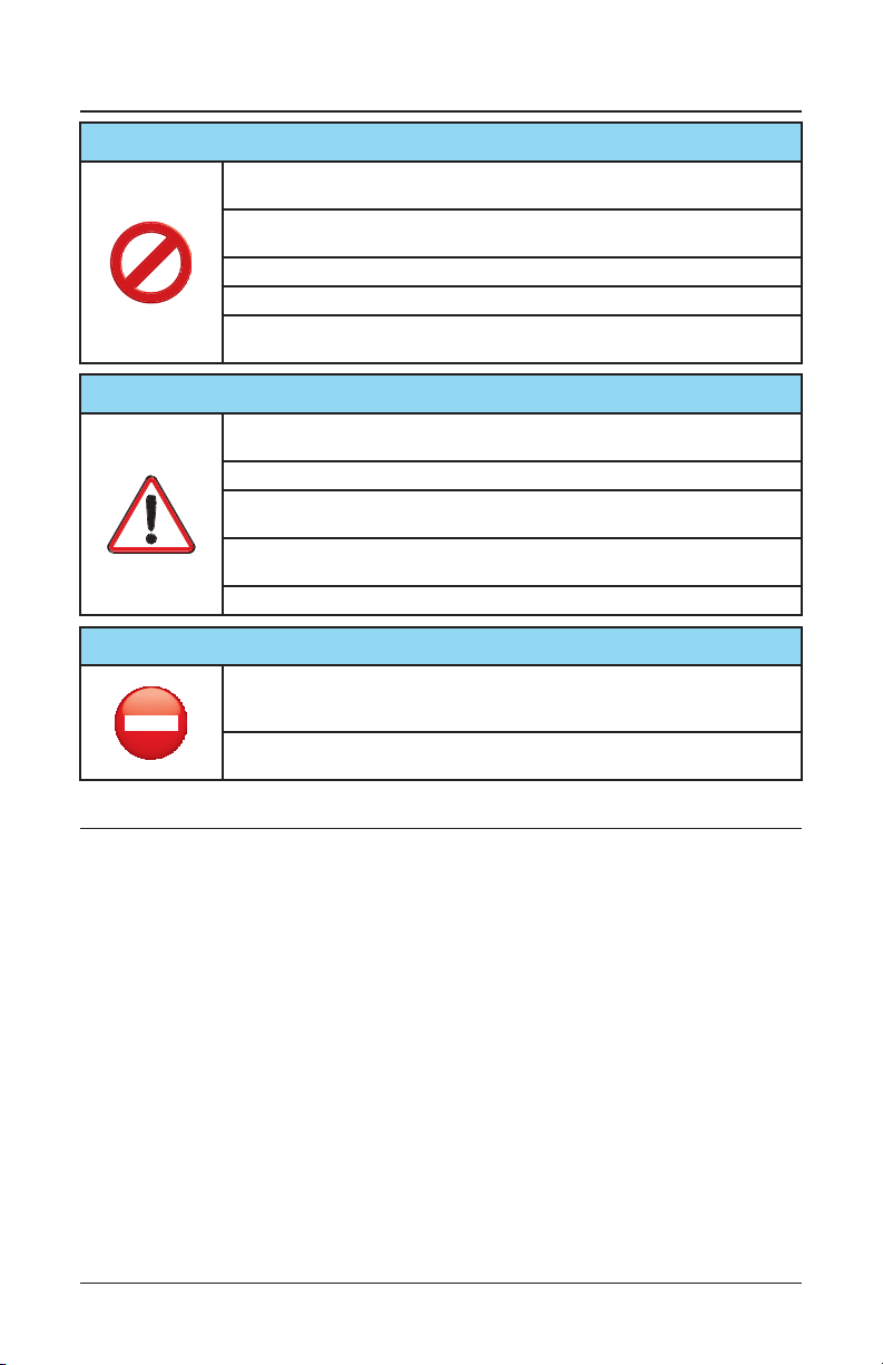
Remove back cord grip cover.
1
Cord Grip Cover
Refer to the remaining sections of the instruction manual to properly setup your display. Once
2
the display is completely setup and ready to use, peel off the release liner on the Butyl Tape
shown below (McMaster part #76385A32) and re-attach the Cord Grip Cover using (10) 4-40
Flat Head Screws.
ON
OFF
Note: Once the release liner is removed
and the Cord Grip Cover is re-attached
the display will be sealed. Make sure
all cables needed are pluged into the
display and the power switch is turned
to the “ON” position before reattaching
the Cord Grip Cover.
Remove release liner
5
Page 6
Installation
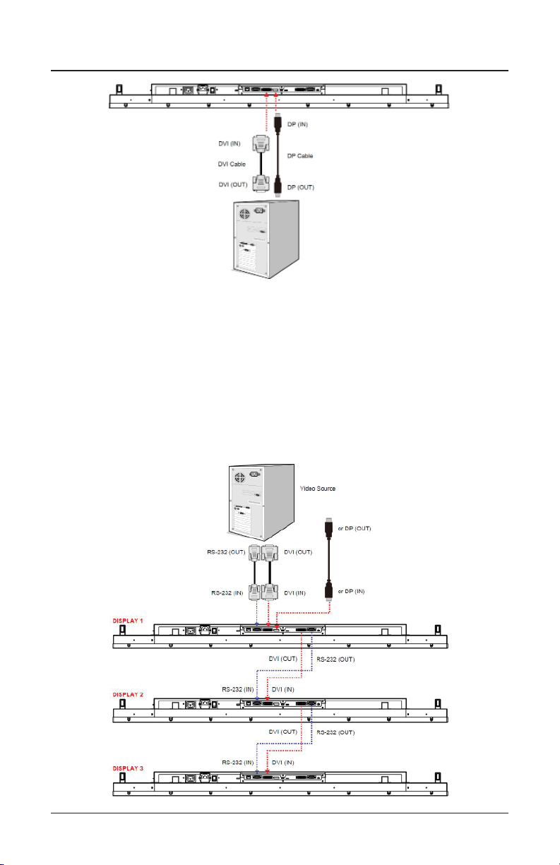
Connecting Multiple Displays for Video Wall Applications
To daisy chain multiple displays for a video wall application, connect a video source to the 1st display
into the chain with the supplied DVI cable (or DP cable) and RS-232 cable. Connect the DVI-OUT of
the 1st display to the DVI-IN of the 2nd display. Using the RS-232 cable provided, connect the RS-232
OUT of the 1st display to the RS-232 IN of the 2nd display. Repeat the connection for the remaining
displays. Use the OSD Menu or Display Manager software to confi gure the size of the video wall and
the position of each display.
Note:
• The maximum number of displays in a Video Wall is 36.
• The DynaScan “Display Manager” application is required to be installed on the PC in order to use
the External Control feature
• The Daisy Chain Setting (video wall function) only supports a resolution of 1920p x 1080p.
6
Page 7
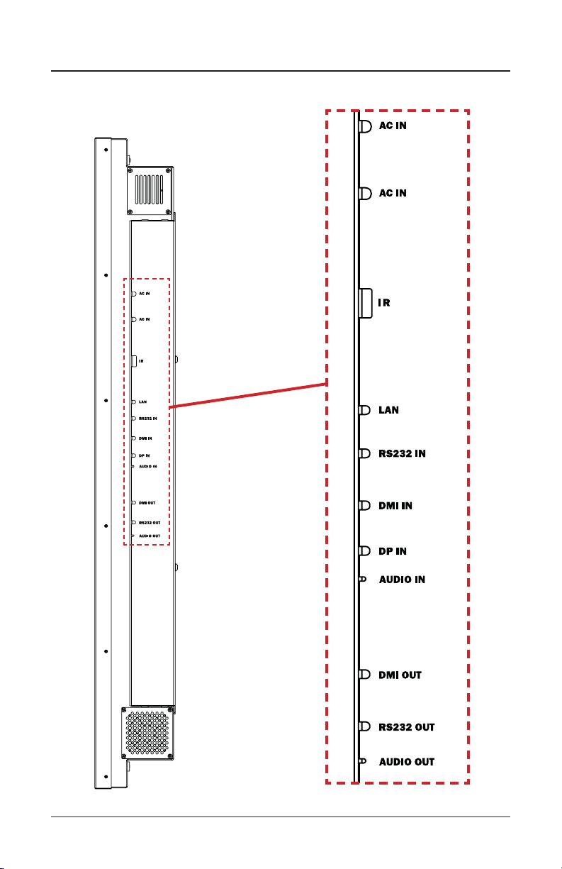
Installation
Connector Positions
7
Page 8

Installation
Input / Output Terminals
1. RJ-45 (IN): RJ45 network input connection for remote control from PC.
2. RS-232 (IN): RS232C network input connection for remote control from PC.
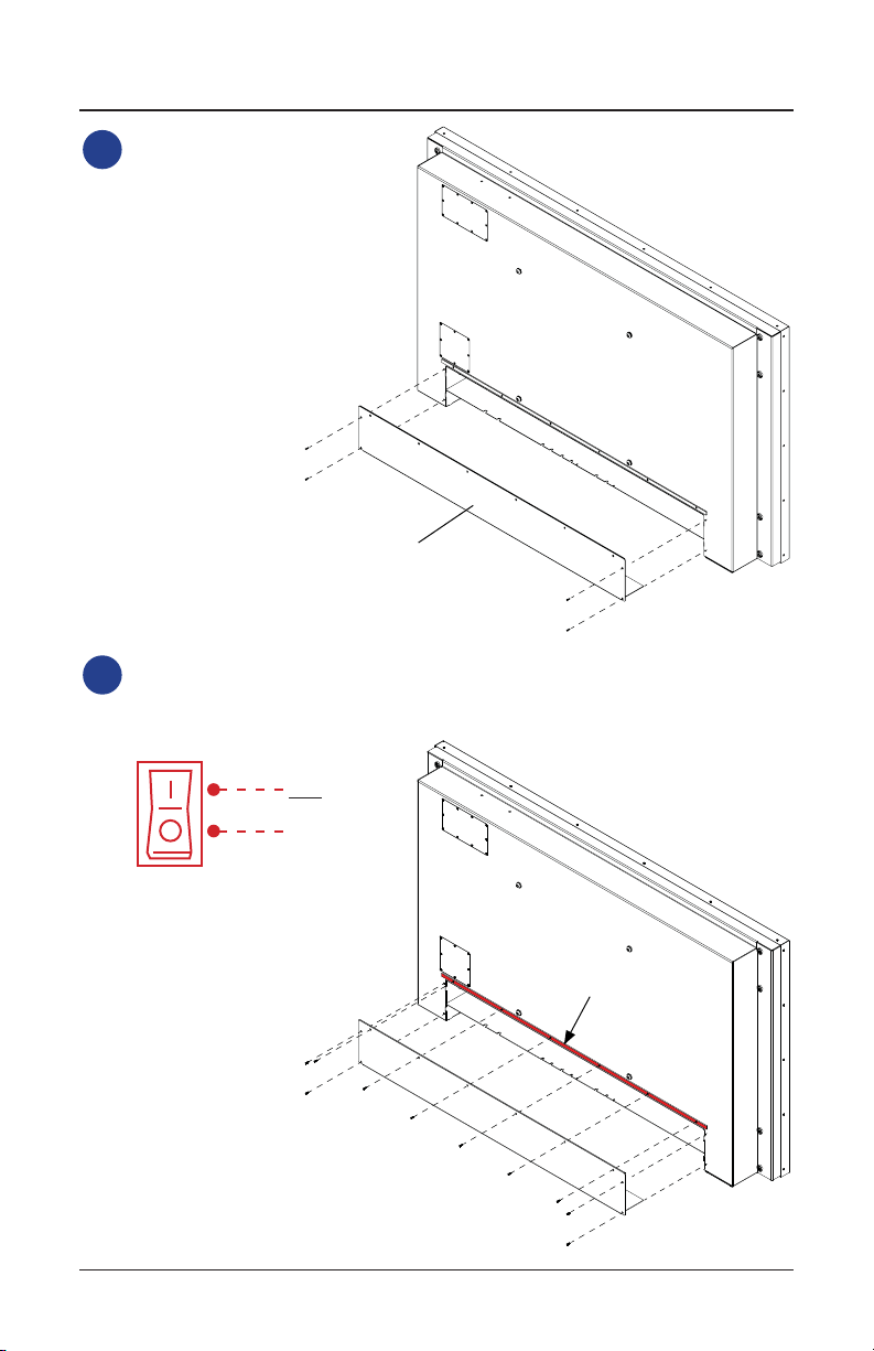
3. DVI (IN): Connect the DVI-D output of a PC, or the HDMI output of an AV device via a DVI-HDMI
cable.
4. DP (IN): Connect the DP output of a PC, or the DP output of an AV device via a DP cable.
5. Audio (IN): Connect the audio input from an external AV device.
6. Extension Connector: Extension Connector for optional IR Extension sensor kit (ESK201).
7. DVI (OUT): Output the signal from DVI IN.
8. RS-232 (OUT): RS232 control function for daisy chain application.
9. Audio (OUT): Connect the audio signal output from Audio IN jack to an external AV device.
10. Power Switch: Press to switch the main power on/off.
11. AC (IN): Connect the supplied power cord to the wall outlet.
12. AC (OUT): AC outlet 110~220V up to 100 Watt.
8
Page 9

Installation
The LCD must be properly installed using a wall mount. Incorrect installation may cause injury or
damage the equipment. Product warranty does not cover the damage caused by imporoper installation.
Mounting
• Hanging the Professional LCD from the ceiling or mounting it on the wall is the responsibility of
the user. Not all ceilings or walls provide enough strength to support the LCD. The LCD may drop
and cause serious injury if it is hanging from the ceiling with insuffi cient support or is mounted on
a slanted wall. Product warranty does not cover improper installation, modifi cation, or damage
caused by natural disasters. It is recommended to have a certifi ed professional to evaluate the
installation site and perform the mounting operation.
• Do not cover the vent and/or the heat sink in order to ensure proper heat dissipation.
• Refer to the installation guide provided by the manufacturer for proper mounting.
When mounting on a wall or hanging from a ceiling
• A wall mount is not included in the accessory. Please purchase a VESA Standard wall mount to
secure the LCD.
• Verify that the mounting location can support the weight of the LCD before installation.
• Do not install the wall mount while the power is turned on as it may cause serious injury due to a
electrical shock.
VESA (mm)
400 x 400 M8
Screw
Specifi cation
Screw Length Number
Greater than 10mm
Smaller than 16mm
400 mm
(4)M8 Screws
4
400 mm
tsuahxEekatnI
MOUNT DISPLAY IN LANDSCAPE ORIENTATION ONLY
Warning:
• The IP56 Display is ONLY intended to be mounted in a landscape orientation. DO NOT MOUNT
DISPLAY IN PORTRAIT ORIENTATION.
• Make sure intake and exaust ports are facing downward and are clear of any obstruction.
9
Page 10

Installation
4 in
Allow a minimum of 4” clearance beneath the display to allow for proper ventilation.
When hanging from a ceiling
• Ensure that the ceiling is strong enough to support the LCD and it accessories. Earthquake,
unexpected vibration and other external forces should be taken into consideration when evaluating
the ceiling strength.
• The LCD should be secured to the building’s structural frame such as a beam rather than light
steel frame or interior decoration.
• Do not use wood screws or dry wall anchors for installation.
Maintenance
• Inspect the fasteners regularly for signs of loosening or deformation. Please perform appropriate
corrective measures when a problem is identifi ed. Neglecting the problem may worsen the
situation.
• Increase the inspection frequency on areas where previous maintenance had occurred to ensure
the problems do not occur again.
10
Page 11

Operating Instructions
Using the Remote Control
noitpircseDmetI
1
2
3
4
5
6
UP
DOWN
MOVE THE CURSOR UP OR CHANGE THE SETTING OF
SELECTED ITEM
MOVE THE CURSOR DOWN OR CHANGE THE SETTING OF
SELECTED ITEM
FFO / NO REWOPREWOP
FFO / NO DSOUNEM
.NOITCELES TNERRUC EHT TIXETFEL
.METI DETHGILHGIH EHT TCELESTHGIR
11
Page 12

Operating Instructions
Using the Rear Panel Controls
Remove Cover Plate
to access rear panel
controls
1
2
3
4
5
6
UP
DOWN
MOVE THE CURSOR UP OR CHANGE THE SETTING OF
MOVE THE CURSOR DOWN OR CHANGE THE SETTING OF
noitpircseDmetI
FFO / NO REWOPREWOP
FFO / NO DSOUNEM
SELECTED ITEM
.NOITCELES TNERRUC EHT TIXETFEL
.METI DETHGILHGIH EHT TCELESTHGIR
SELECTED ITEM
12
Page 13

Navigating the On Screen Display (OSD) Menu
Press the MENU button on either the rear panel control or remote control to show the OSD. Use the
navigation arrows to select and adjust the menu items.
noitpircseDtluafeD2 metI1 metI
Set the Main input to display. (DP(Display Port)
or DVI)
Set the Failover input to display. (DP(Display
Port) or DVI)
Input
Source
Main DP
Failover DVI
Picture
noitpircseDtluafeD2 metI1 metI
Color
Temperature
R 100
G 100
B 100
Contrast 50 Adjust the contrast level. Range 0 – 100.
Gamma Native Adjusts the Gamma value.
D65
Select the color temperature. (User, D93,
D65 and D55).
Adjust the red light level. Range 0 – 100.
Note: The feature is only supported on User
mode.
Adjust the green light level. Range 0 – 100.
Note: The feature is only supported on User
mode.
Adjust the blue light level. Range 0 – 100.
Note: The feature is only supported on User
mode.
13
Page 14

Navigating the On Screen Display (OSD) Menu
Time
Current Time HH:MM
Power Control
Timer
Off Turn on / off automatic power schedule
Note: The internal clock will continue to
function when the power is turned off.
noitpircseDtluafeD2 metI1 metI
Set the clock.
emit no-nrut teSMM:HHemiT nO rewoP
emit ffo-nrut teSMM:HHemiT ffO rewoP
Video Wall
noitpircseDtluafeD2 metI1 metI
Number of Rows 1
Number of
Columns
Row Position 1 Vertical position in a video wall.
Column Position 1 Horizontal position in a video wall.
Bezel
Compensation
1
On
Set number of rows in a video wall.
Note: The maximum number of rows in a daisy
chain is 15
Set number of columns in a video wall.
Note: The maximum number of columns in a
daisy chain is 15
Choose to turn the frame compensation
function on or off. When turned on, the
display will adjust the image to compensate
the width of display bezels in order to
accurately display the image.
14
Page 15

Navigating the On Screen Display (OSD) Menu
To turn On / Off the auto brightness
Note: If the AUTO BRIGHTNESS is off, the
screen brightness will remain at HIGH
LEVEL brightness value. If the AUTO
BRIGHTNESS is on (Auto), the display
Auto Brightness Off
Backlight
High Level 100 Adjust the highest brightness leve. Range 0-100
Low Level 20 Adjust the lowest brightness level. Range 0-100
High Level Time HH:MM Set high level time.
Local Dimming Medium
brightness adjusts according to the ambient
light. When ambient light is bright, the
screen will adjust to the HIGH LEVEL
brightness value set; when ambient light is
dark, the screen will adjust to the LOW
LEVEL brightness value set. When the
Timer mode is set, the display will
automatically switch the brightness
according to the time set.
Adjust the contras. High is the highest contrast.
Off is the lowest contrast.
noitpircseDtluafeD2 metI1 metI
adjustment.
.emit level wol teSMM:HHemiT leveL woL
Network
noitpircseDtluafeD2 metI1 metI
Choose to enable or disable the DHCP
DHCP On
IP 192.168.0.100 Assign IP address.
Mask 255.255.255.0 Assign Subnet mask.
Gateway 192.168.0.1 Assign Default gateway
function. If enabled, the display will assign
the IP address, Subnet mask and Default
gateway automatically. If disabled, the
following values will be entered manually.
15
Page 16

Navigating the On Screen Display (OSD) Menu
Change the Menu orientation. The Menu
can be displayed in either LANDSCAPE or
PORTRAIT mode.
Turn on / off image burn-in protection.
Set image burn-in protection interval.
Choose to use the remote control function
RS232 or Network.
Enable/disable the remote control for Menu.
Note: When disabled, the remote control
function can be enabled again from the
control panel on the display or through the
DynaScan “Display Manager” application.
When in Power Off Mode, RS-232 controls
do not function. Only [Main Power Switch]
on the display or [Power Button] on the
remote control can wake up the display.
Selects the black level to adjust the screen
gray scale. “Limited” for video source uses
16 to 235 levels for R/G/B, such as HDMI.
“RGB Full” for video source uses all levels
from 0 to 255 levels.
Restore all settings to default.
Note: It does not modify CURRENT TIME,
POWER ON TIME and POWER OFF TIME.
Advance
Display Mode Landscape
Screen Saver Off
Remote Control RS232
IR Control On
Power Off Mode Standby
Black Level Limited
Reset to Default
Setting
Off
noitpircseDtluafeD2 metI1 metI
16
Page 17

Navigating the On Screen Display (OSD) Menu
Resolution 1920x1080 Input resolution.
Model DS552LT4 The display’s model.
It will enter into protection mode when the
display internal temperature is over heat.
Mode 0 = Brightness 50%.
Mode 1 = Brightness 25%.
Mode 2 = Brightness 03%.
When the temperature is decreased to exit
the protection, the brightness will restore to
100% and Over Heat Protection is disabled.
When any of the cooling fans on the display
rear side is failure and stops running, the
Fan Alarm will appear and blink, and reduce
the brightness to 25%. Be sure to contact
the service engineer for repair.
Information
1
Over Heat
Protection
Fan Alarm Not displayed
Not displayed
noitpircseDtluafeD2 metI1 metI
.rebmun laires s’yalpsid ehTrebmuN laireS
noitpircseDtluafeD2 metI1 metI
Information
2
Some functions may not be available for all models.
* Adjusted value: Each R/G/B value for this product has been individually adjusted during production to
a preset color temperature of 6500K.
.noisrev W/H ehTerawdraH
.noisrev W/F ehTerawmriF
17
Page 18

Specifi cations
Panel
Power
Mechanical Specs
User Interface hsilgnEegaugnaL DSO
Environment
Fuse 5A
Contrast Ratio
Power On Mode Typ. 205W / Max. 290 W
Monitor Dimensions
(LxHxD)
rutarepmeT noitarepO
4TL255SDledoM
sehcni 46.65eziS lenaP DCL
0801 x 0291noituloseR evitaN
).pyT( ²m/dc 0053ssenthgirB
3,000:1 (Static)
10,000,000:1 (Dynamic)
).pyT( sm9emiT esnopseR
°871/°871elgnA gniweiV
).pyT( srh 000,001emiT efiL
H2 ,%5.1 RAecafruS lenaP
lanretnIylppuS rewoP
001egatloV detaR ~240V, 50 / 60Hz
W1 <edoM ybdnatS
W001 <tuO CA
dnuora lla )mm7.12( ni68.htdiW lezeB
kcalBroloC tenibaC
49.3in x 28.6in x 5.9in
sbl 59thgieW rotinoM
004 x 004 gnitnuoM ASEV
C05 - C04-e
C06 - C04-erutarepmeT egarotS
gnisnednoC-noN %08ytidimuH
• Design and specifi cations are subject to change without notice
• The resolution of DVI-D out is 1920 x 1080 (1080p) only.
18
Page 19

Input Mode
Active Resolution
H Pixels V Lines
640 480 60 Hz 25.175 MHz 4:3
720 480
800 600 60 Hz 40 MHz 4:3
1024 768 60 Hz 65 MHz 4:3
1280 720
1280 768 60 Hz 79.5 MHz 5:3
1360 768 60 Hz 85.5 MHz 16:9
1920 1080
Refresh Rate Pixel Rate Aspect Ratio
50 Hz 27 MHz 4:3
59.94 Hz 27 MHz 4:3
50 Hz
60 Hz
50 Hz
60 Hz
74.25 MHz 16:9
148.5 MHz 16:9
19
Page 20

Troubleshooting
noituloS dednemmoceReussI
• Check whether the DVI in cable is completely plugged in.
• Check whether the main switch is in the ON position, and the
No image is displayed
Nothing happens when
switching the main switch on.
Image is unstable. • Check whether the DVI in cable is completely plugged in.
The remote control does not
work.
Auto on/off does not work or
does not function properly.
Cannot control the display
remotely via RS-232
If you are still having trouble with your IP56 Display, contact your dealer directly for more assistance.
power cord is completely plugged in.
• Check whether the image source’s resolution is set to 1920 x
1080 (1080p).
• Check whether the DVI cable is damaged or bent excessively.
• Unplug the power cord from the socket and plug it in again after
a few seconds to reset the Signage. Note: Unplugging the power
cord will not change the settings.
• Check whether there are batteries in the remote control.
• Check the batteries for freshness, polarity, etc.
• Check whether the remote is in the operation range.
• Bright light may interfere with the remote control. Please avoid
using the remote control near special fl uorescent lights or neon
lights.
• Check whether the TIMER setting in the menu is set to “OFF”.
• Check whether the “Power On Time” and “Power Off Time”
settings are set correctly.
• Check whether the RS-232 cable is connected properly.
20
Page 21

Dimensions
21
 Loading...