

Page 1
OPERATING INSTRUCTIONS
The LG-417 is activated by strategically located pressure pad. With a normal shooting grip,
your middle finger will naturally hit the pressure pad whether shooting right or left-handed.
A master ON/OFF switch is located on the left side of Lasergrip and is activated and deactivated
by pressing master switch firmly for less than two seconds. Turning the master switch OFF will
NOT increase battery life.
PLEASE READ ENTIRE OWNER’S MANUAL PRIOR TO INSTALLING AND USING YOUR NEW LASERGRIPS.
Crimson Trace
800-442-2406 or 503-783-5333
Fax: 503-783-5334
Customer Service E-Mail: customer@crimsontrace.com
www.crimsontrace.com
27-4178 RE V 010 01/11
www.crimsontrace.com
Fax: (503) 783-5334
Tel: (800) 442-2406
Wilsonville, OR 97070 USA
9780 SW Freeman Dr.
LG -41 7 fo r
GL O CK 17, 17 L , 1 9, 2 2 , 2 3, 3 1, 32 , 34, 3 5, 37, & 38
I N S TA L L A TI ON H A ND B O O K
THANK YOU FOR SELEC TING THE FINEST LASER
SI GH TI NG SY ST EM: CR IM SON T RA CE LA SE RGR IP S
AN D LA SE RGU AR D. WH EN I T CO ME S TO S PEE D,
ACCUR ACY AND SEC URIT Y, CRIMSON TR ACE IS THE
TOP CHOI CE OF LAW ENFOR CEME NT, MILITA RIES AND
LEGAL LY ARMED CITIZENS AROUND THE WORLD .
Page 2
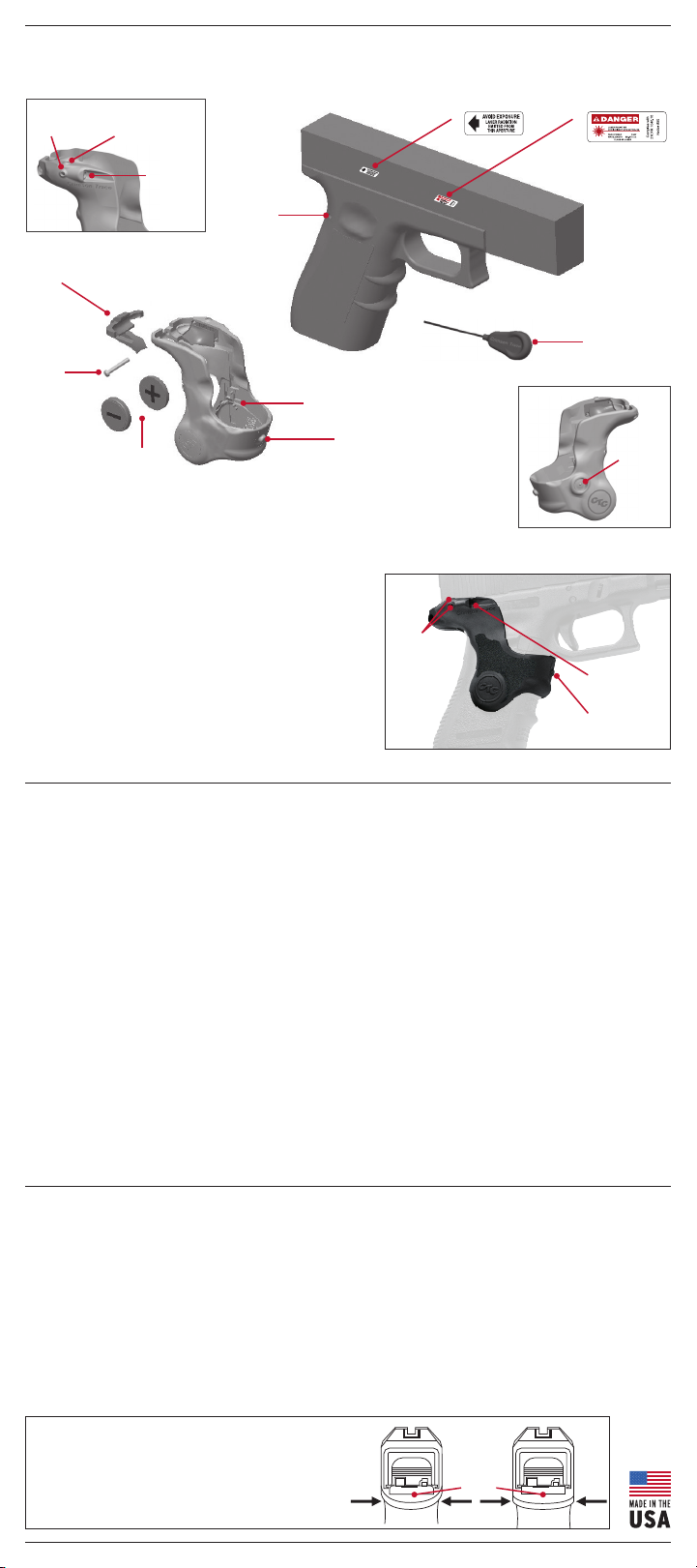
GLO CK 1 7, 1 7L, 1 9, 22 , 2 3 , 3 1, 32, 3 4 , 35, 37, & 38 [L G - 41 7]
Windage
Adjustment
Clamp
Stock Grip
Screw
Elevation
Adjustment
Batteries
Laser
Apertu re
Trigger
Housing Pin
Master ON/OFF Button
(on left side of Lasergrips)
BATTERIES
Two (2) CR2032 or DL2032 Lithium Cells.
PRODUCT SPECIFICATIONS
BEAM INTENSITY: 5mW peak, 633 nm, Class 3R laser
DOT SIZE: Approximately 0.5 inches diameter at 50 feet
BATTERIES: Two #2032 lithium batteries;
ACTIVATION: Front-located integrated momentary
WARRANTY: Three-year full warranty
This product complies with 21 CFR 1040.10
over four hours of illumination
pressure pad and master ON/OFF switch
Activation Pad
Windage and
Adjustment
Elevation
A.
B.
Armorer’s Tool
Laser
Aperture
Activation
Pad
Master
ON/OFF
Switch
INSTALLATION INSTRUCTIONS
1. Make sure firearm is unloaded. Remove magazine and double check that the chamber is empty.
(See “Four Basic Rules Of Firearm Safety” in Owner’s Manual).
2. Place one battery straight down into battery well on each Side, with the flat, (+) side visible.
3. Slide CTC Lasergrips® over the bottom of the firearm and push up until the Lasergrips pops into place.
4. Slide the clamp into the back of the Lasergrips. Insert screw (from right to left) and use armorer’s
tool to tighten down.
5. Lasergrips are default set at the factory to be in the “ON” position. Test the master on/off switch
(located on the left side of the Lasergrip) by pressing firmly for less than two seconds, and then
pressing the activation pad. The lasershould not activate. To turn back on, firmly press master on/off
switch less than two seconds.
6. Confirm that laser and iron sights are in alignment. Laser dot should rest on top of front site post
with correct iron sight picture. Lasergrips are sighted-in at the factory to 50 feet, but can be
fine-tuned to any point of impact by adjusting for windage and elevation. (See Laser Sight Owner’s
Handbook for complete sighting information.)
LASER SAFETY LABELING
IMPORTANT: LASER PRODUCTS MUST ONLY BE OPERATED WITH THE SAFETY LABEL APPLIED TO THE FIREARM.
Labels could not be affixed to the product but are supplied and must be installed as indicated below:
A. Attach the “Aperture” warning label with the arrow pointing to the laser aperture.
B. Attach the “Danger” warning label to the outside of the firearm.
Use caution when activating the laser to avoid direct eye exposure, which can result in permanent
eye damage. Follow all precautions as outlined by the firearms manufacturer. Keep this and all firearm
related products locked and secured from children or other unauthorized users.
NOTE: A SMALL NUMBER OF GLOCKS HAVE A SLIGHTLY
DIFFERENT FRAME CONFIGURATION DUE TO MANUFACTURING
TOLERANCES (SEE IMAGES) THE VAST MAJORITY OF THE
FRAMES WILL UTILIZE THE SMALL CLAMP (IMAGE 1).
If your Glock frame looks like image #1 use the SMALL (S) clamp.
If your Glock frame looks like image #2 use the LARGE (L) clamp.
Beaverta il
Image 1 Image 2
 Loading...