

Page 1
SPECIFICATION & DESIGN MANUAL
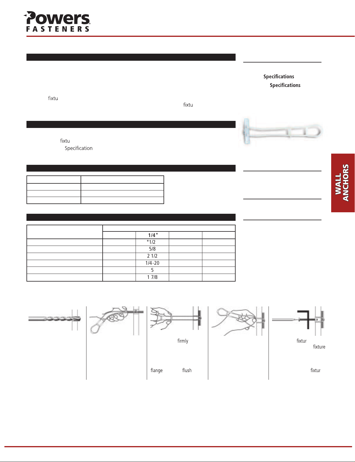
Strap-Toggle
TM
Strap-Toggle
TM
Hollow Wall Anchor
PRODUCT DESCRIPTION
The Strap-Toggle is a heavy duty hollow wall anchor designed for use in base materials such
as plaster, wallboard, concrete block or hollow tile. The Strap-Toggle is a pre-assembled
anchor consisting of a carbon steel wing and a locking cap/ratchet leg assembly molded
from engineered plastic. It is available in 3/16", 1/4", 3/8" and 1/2" sizes. When compared
to traditional toggles, this unique anchor can be installed in a smaller hole and does not
require a
wall thickness of up to 2 1/2" while using a shorter bolt. The bolt and
and removed as often as necessary.
re or sc
rew to set it. The anchor can be easily adjusted to accommodate a
re may be installed
FEATURES AND BENEFITS
• Adjustable to accommodate various wall thickness up to 2 1/2"
• Allows for
• Federal GSA
for a captive toggle (superseded)
re and bolt/screw removal and re-anchoring
– Meets the descriptive requirements of FF-B-588D, Type V
MATERIAL SPECIFICATIONS
Anchor Component Component Material
Wing
Plating ASTM B633, SC1, Type III, (Fe/Zn 5)
Anchor Body Engineered Plastic
AISI 1010
SECTION CONTENTS Page No.
General Information ................. 283
Material
Installation
Performance Data...................... 284
Ordering Information................ 284
............. 283
........ 283
Strap-Toggle
ANCHOR MATERIALS
Engineered Plastic
Carbon Steel (Wing)
ANCHOR SIZE RANGE (TYP.)
3/16" to 1/2" diameter
INSTALLATION SPECIFICATIONS
Anchor Diameter,
Dimension
ANSI Drill Bit Size,
Thread Size (UNC) 3/16-24 1/4-20 3/8-16 1/2-13
Max.Tightening Torque,
Minimum Clearance (in.) 1 7/8 1 7/8 1 7/8 1 7/8
*9/16" diameter bit may be required for very dense materials.
**13/16" diameter bit may be required for very dense materials.
d
(in.) *1/2 *1/2 **3/4 **3/4
bit
T
, (ft-lbs) 5 5 5 5
max
3/16" 1/4" 3/8" 1/2"
d
118/58/5).ni( eziS paC
Installation Guidelines
Drill the proper size hole
into the cavity of the
hollow base material.
Position the wing parallel
to the plastic legs and slide
the anchor through the
drilled hole into the hollow
cavity.
Pull the wing against
the inside wall of the
hollow material using the
ring, then slide the plastic
cap forward until the
is seated
against the work surface.
Place your thumb between
the plastic straps and snap
the straps off.
SUITABLE BASE MATERIALS
Wallboard
Hollow Concrete Masonry
2/1 22/1 22/1 22/1 2).ni( egnaR pirG
Position the e. Insert
the bolt through the
and tighten. The minimum
bolt length should be at
least 1/2" longer than the
combined wall and
e.
Page 2
Strap-Toggle
TM
SPECIFICATION&DESIGN MANUAL
PERFORMANCE DATA
Ultimate Load Capacities for Strap-Toggle in Wallboard
Anchor
Diameter
d
in.
(mm)
3/16 120 240 130 285 195 380 205 440
(4.8) (0.5) (1.1) (0.6) (1.3) (0.9) (1.7) (0.9) (2.0)
1/4 130 270 145 295 210 420 215 470
(6.4) (0.6) (1.2) (0.7) (1.3) (0.9) (1.9) (1.0) (2.1)
3/8 135 275 150 300 220 420 230 475
(9.5) (0.6) (1.2) (0.7) (1.4) (1.0) (1.9) (1.0) (2.1)
1/2 140 290 150 355 220 430 230 485
(12.7) (0.6) (1.3) (0.7) (1.6) (1.0) (1.9) (1.0) (2.2)
1. The values listed above are ultimate load capacities which should be reduced by a minimum safety factor of 4.0 or greater to determine the allowable working load.
3/8" Wallboard 1/2" Wallboard 5/8" Wallboard 3/4" Wallboard
Tension Shear Tension Shear Tension Shear Tension Shear
lbs. lbs. lbs. lbs. lbs. lbs. lbs. lbs.
(kN) (kN) (kN) (kN) (kN) (kN) (kN) (kN)
1
Allowable Load Capacities for Strap-Toggle in Wallboard
Anchor
Diameter
d
in.
(mm)
3/16
(4.8) (0.1) (0.3) (0.2) (0.3) (0.2) (0.4) (0.2) (0.5)
1/4 35 70 35 75 55 105 55 120
(6.4) (0.2) (0.3) (0.2) (0.3) (0.2) (0.5) (0.2) (0.5)
3/8 35 70 40 75 55 105 60 120
(9.5) (0.2) (0.3) (0.2) (0.3) (0.2) (0.5) (0.3) (0.5)
1/2 35 75 40 90 55 110 60 120
(12.7) (0.2) (0.3) (0.2) (0.4) (0.2) (0.5) (0.3) (0.5)
1. Allowable load capacities listed are calculated using an applied safety factor of 4.0.
3/8" Wallboard 1/2" Wallboard 5/8" Wallboard 3/4" Wallboard
Tension Shear Tension Shear Tension Shear Tension Shear
lbs. lbs. lbs. lbs. lbs. lbs. lbs. lbs.
(kN) (kN) (kN) (kN) (kN) (kN) (kN) (kN)
30 60 35 70 50 95 50 110
Ultimate and Allowable Load Capacities for Strap-Toggle in Hollow Concrete Masonry
Anchor
Diameter
d
in.
(mm)
Drill
Bit
Diameter
d
bit
in.
(mm)
Tension Shear Tension Shear
lbs. lbs. lbs. lbs.
(kN) (kN) (kN) (kN)
1
f´
≥
1,500 psi (10.4 MPa)
m
1,2
daoL elbawollA daoL etamitlU
3/16 1/2
(4.8) (12.7) )7.0()0.1()3.3()9.4(
1/4 1/2
(6.4) (12.7) )3.1()2.1()4.6()1.6(
3/8 3/4
(9.5) (19.1) )1.2()3.1()5.01()5.6(
1/2 3/4
(12.7) (19.1) )7.2()6.1()4.31()7.7(
1. Tabulated load values are for anchors installed in minimum 6-inch wide, Grade N, Type II, medium and normal-weight concrete masonry units. Mortar must be minimum Type N.
2. Allowable loads are based on average ultimate values using a safety factor of 5.0.
051512047080,1
582072024,1553,1
564582033,2534,1
595543089,2027,1
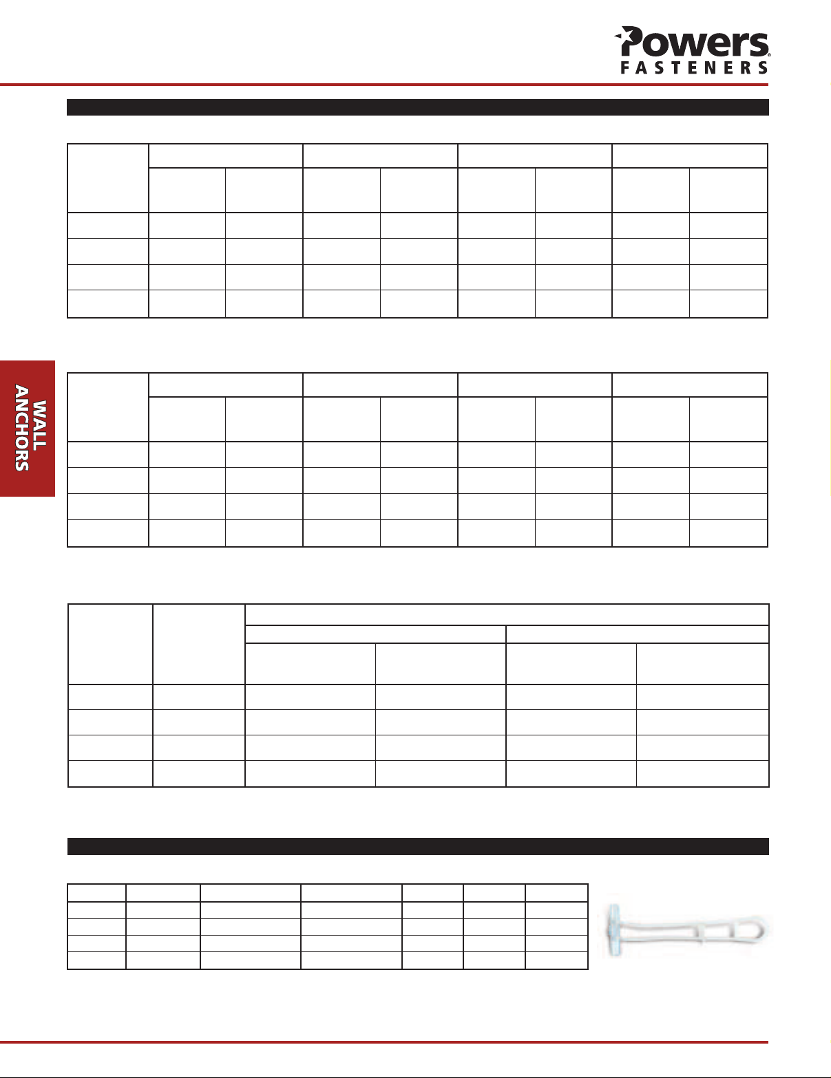
ORDERING INFORMATION
Strap-Toggle (Not packaged with screws)
Cat. No. Anchor Size Drill Diameter Wall Thickness Std. Box Std.Carton Wt./100
4052 3/16" x 4" 1/2" 3/8"- 2 1/2" 50 300 3 1/2
4054 1/4" x 4" 1/2" 3/8"- 2 1/2" 50 300 3 1/2
4056 3/8" x 4" 3/4" 3/8"- 2 1/2" 25 150 5
4058 1/2" x 4" 3/4" 3/8"- 2 1/2" 25 150 5
 Loading...