

Page 1

Crestron SRD-ANT-4-PAK
Antenna System
Installation Guide
Page 2

This document was prepared and written by the Technical Documentation department at:
Crestron Electronics, Inc.
15 Volvo Drive
Rockleigh, NJ 07647
1-888-CRESTRON
• Read and Retain Instructions – Read all Instructions before
Important Safety Instructions
operating equipment and save for future reference.
• Outdoor Antenna Grounding – The antenna and coaxial cable
connecting to the unit should be properly grounded to provide
protection against voltage surges and built-up static charges. Article
810 of the National Electrical Code (NEC), ANSI/NFPA 70, provides
information with regard to proper grounding of the mast and
supporting structure, grounding of the lead-in wire to an antenna
discharge unit, size of grounding conductors, location of antennadischarge unit, connection to grounding electrodes, and requirements
for the grounding electrode.
• Power Lines – An outside antenna system should not be located in
the vicinity of overhead power lines or electric light or power circuits,
or where they can fall into such power lines or circuits. When
installing an outside antenna system, extreme care should be taken to
keep from touching such power lines or circuits, as contact with them
might be fatal.
All brand names, product names and trademarks are the property of their respective owners.
©2008 Crestron Electronics, Inc.
Page 3

Crestron SRD-ANT-4-PAK Antenna System
Contents
Antenna System: SRD-ANT-4-PAK 1
Introduction................................................................................................................................1
Block Diagram.............................................................................................................2
Specifications...............................................................................................................2
Included Items .............................................................................................................3
Industry Compliance....................................................................................................4
Installation .................................................................................................................................5
Installation Notes.........................................................................................................5
Wall Mounting.............................................................................................................5
Pole Mounting .............................................................................................................6
Hookup ........................................................................................................................6
Aiming the Antenna.....................................................................................................7
Problem Solving.........................................................................................................................8
Troubleshooting...........................................................................................................8
Further Inquiries ..........................................................................................................8
Future Updates.............................................................................................................9
Appendix: Azimuth and Elevation Pointing Guide..................................................................10
Return and Warranty Policies ..................................................................................................13
Merchandise Returns / Repair Service.......................................................................13
CRESTRON Limited Warranty.................................................................................13
Installation Guide – DOC. 6723A Contents • i
Page 4

Page 5

Crestron SRD-ANT-4-PAK Antenna System
Antenna System:
SRD-ANT-4-PAK
Introduction
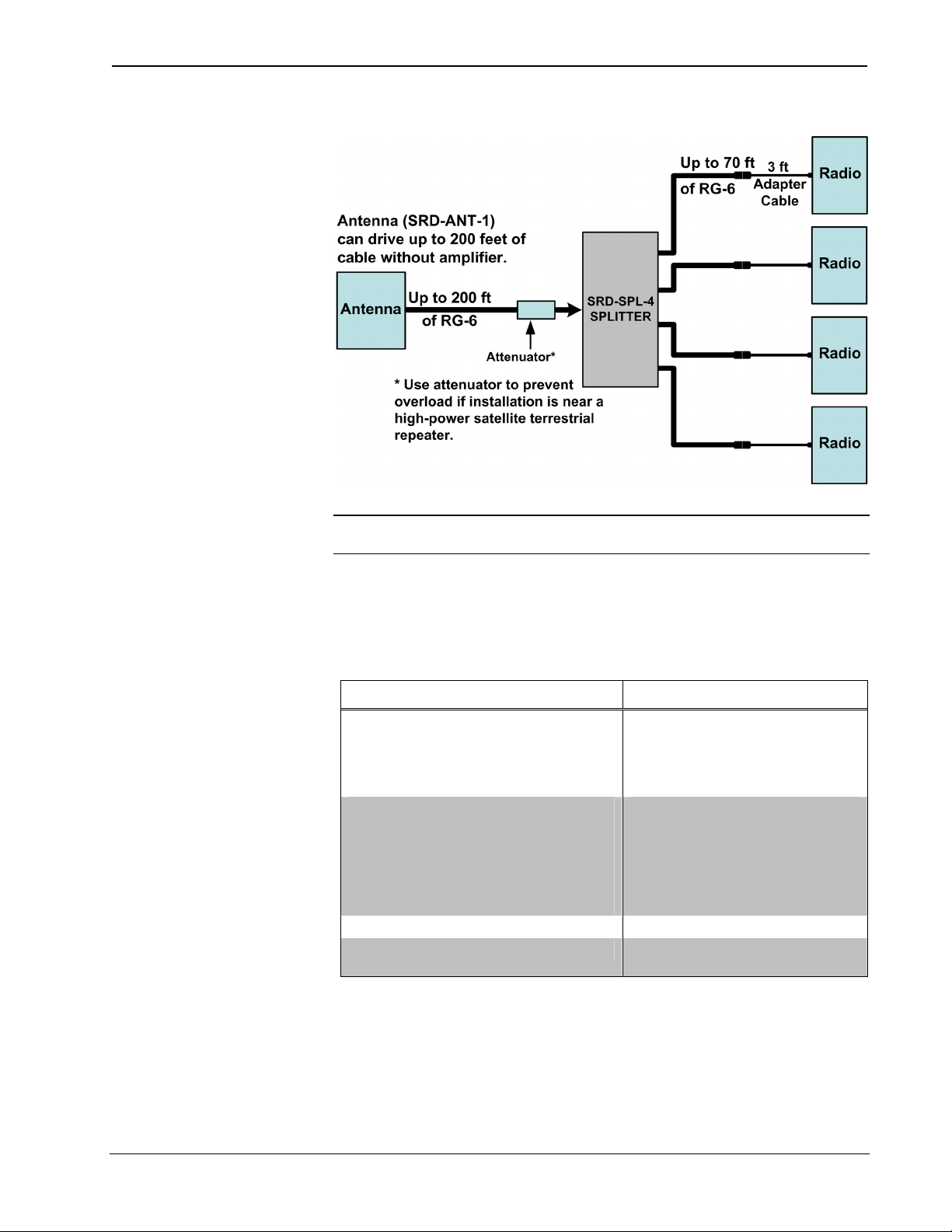
The SRD-ANT-4-PAK is a high quality outdoor antenna system designed for use
with up to four Crestron® XM or SIRIUS® satellite radio tuners. The inclusion of an
SRD-SPL-4 Four-Way Amplified Splitter enables distribution of the antenna signal
to four separate tuners while allowing the antenna to be positioned up to 200 feet
(cable length) from the tuners using standard RG-6 cable (not included).
The antenna features a considerably narrower beam width compared to standard
consumer antennas, achieving superior gain and multi-path rejection. Additional
front end filtering provides excellent rejection to nearby out-of-band RF signals from
sources such as Wi-Fi, cellular telephones, and cordless telephones.
A wall mount bracket with elevation and azimuth adjustments is provided for
installation of the antenna to any horizontal or vertical flat surface. The additional
U-bolt and saddle enable mounting to a pole (not included) up to two inches in
diameter. Connections between the antenna and splitter are achieved using industry
standard RG-6 cable and F-type connectors (not supplied).
Four 3-foot F-to-SMB adapter cables are included for connecting each tuner to the
splitter outputs. If needed, standard RG-6 cable with male F-connectors (not
supplied) may be used to extend the output cable lengths up to 70 feet from each
individual splitter output to the tuners. Adding an SRD-AMP-1 line amplifier (sold
separately) at the input of the splitter will enable longer output cable lengths of up to
200 feet each.
NOTE: Unused splitter outputs do not have to be terminated for proper operation.
A 20 dB power passing attenuator is also included for use in preventing overload of
the splitter input in any installation that is located near a high power satellite radio
terrestrial repeater.
Installation Guide – DOC. 6723A Antenna System: SRD-ANT-4-PAK • 1
Page 6
Antenna System Crestron SRD-ANT-4-PAK
Block Diagram
NOTE: In this typical layout example, the sum total of all the cable segments
between the antenna output and the most distant radio should not exceed 275 feet.
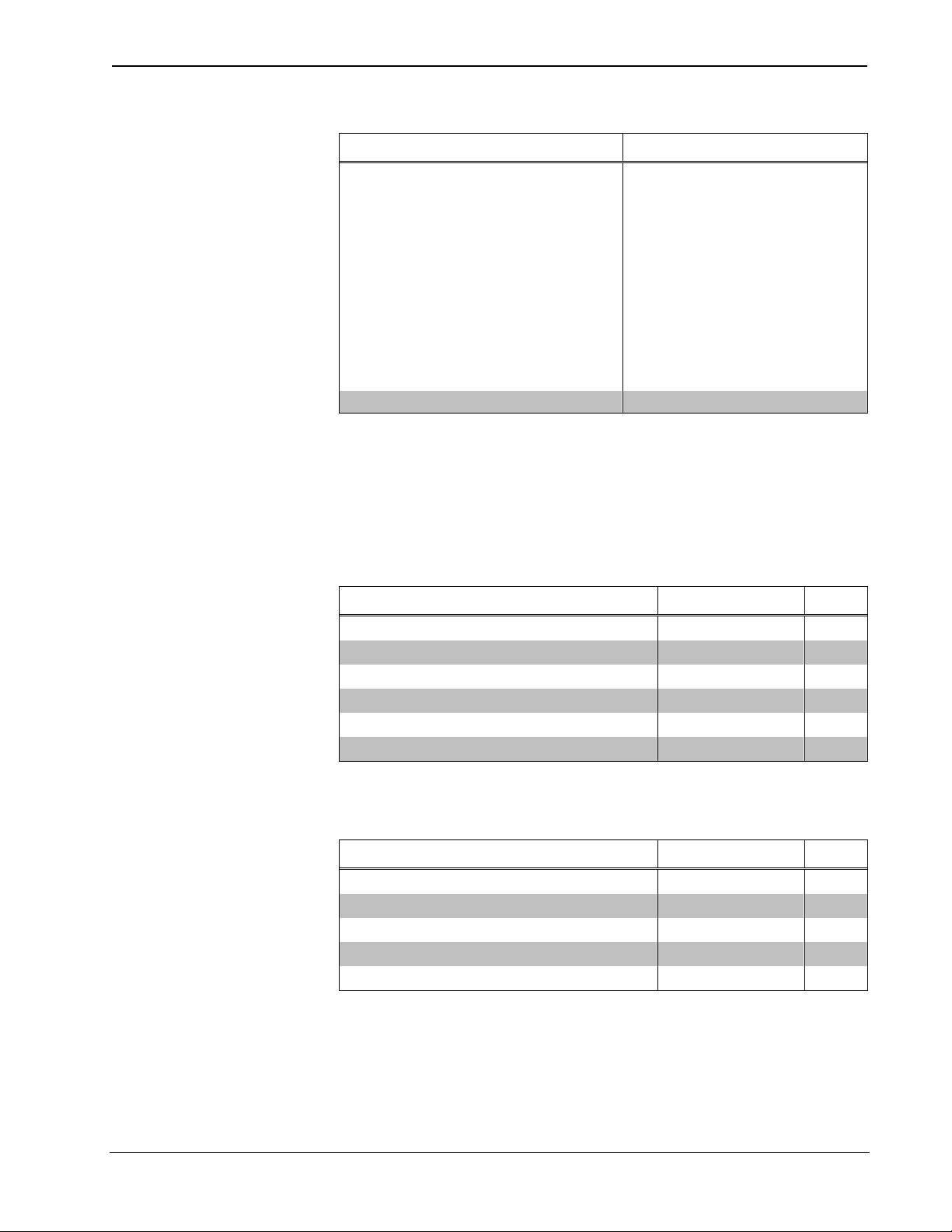
Specifications
Following are specifications for the SRD-ANT-4-PAK.
SRD-ANT-4-PAK Specifications
SPECIFICATION DETAILS
Antenna
Gain
Polarization
Output connector
Wind resistance
Splitter
Gain at 2.335 GHz
Max noise figure
Max input signal
Current consumption
DC power passing
DC voltage drop (output to input)
Environmental Temperature -40° to 150°F (-40° to 66°C)
Humidity
(Continued on following page)
12dBi (Typical)
Left hand circular
F-female
Up to 100 MPH
8 dB min
3 dB
-10 dBm1
40 – 100 milliamps
all ports (diode protected)
0.5 VDC typical
0% to 98% RH
(non-condensing)
2 • Antenna System: SRD-ANT-4-PAK Installation Guide – DOC. 6723A
Page 7
Crestron SRD-ANT-4-PAK Antenna System
SRD-ANT-4-PAK Specifications (Continued)
SPECIFICATION DETAILS
Overall Dimensions
Antenna
Height
Width
Depth
Wall Mount3
Height
Width
Length
Splitter
Height
Width
Length
Weight 2.6 lbs (1.2 Kg)
1. Specification is achieved with supplied 20 dB attenuator.
2. Depth is measured from the interface connector to the high point of the convex antenna cover.
3. Wall mount dimensions include the antenna mounting bracket.
7.75 in (19.69 cm)
7.75 in (19.69 cm)
1.19 in (3.03 cm)2
5.38 in (13.67 cm)
3.38 in (8.59 cm)
11.63 in (29.54 cm)
0.88 in (2.24 cm)
3.75 in (9.53 cm)
2.83 in (7.19 cm)
Included Items
The items included in the SRD-ANT-4-PAK are listed in the following table and
illustrated on the following page.
SRD-ANT-4-PAK Included Items
DESCRIPTION PART NUMBER QTY
Satellite Radio Antenna SRD-ANT-1 1
Wall Mount Bracket 2021597 1
Pole Mount Saddle 2021596 1
Mounting Screws and Hardware Package 4506257 1
Weather Boot 2021595 1
Four-way Amplified Splitter SRD-SPL-4 1
The items included with the SRD-SPL-4 are listed in the following table and are also
illustrated on the following page.
SRD-SPL-4 Kit Included Items
DESCRIPTION PART NUMBER QTY
4-Way Splitter w/Mounting Screws 2021578 1
F-female to SMB-plug, 3 ft cables 2021515 4
F-male to F-male Coupler 2021526 4
20 dB Power Passing Attenuator 2021580 1
SMB-jack to F-male Adapter 2021579 1
Installation Guide – DOC. 6723A Antenna System: SRD-ANT-4-PAK • 3
Page 8

Antenna System Crestron SRD-ANT-4-PAK
SRD-ANT-4-PAK and SRD-SPL-4 Included Items
Industry Compliance
As of the date of manufacture, the SRD-ANT-4-PAK has been tested and found to
comply with specifications for CE marking and standards per EMC and
Radiocommunications Compliance Labelling.
4 • Antenna System: SRD-ANT-4-PAK Installation Guide – DOC. 6723A
Page 9
Crestron SRD-ANT-4-PAK Antenna System
Installation
Installation Notes
• Mount the antenna outdoors with the supplied wall mount or pole mount
accessories. Installation indoors or behind windows is not recommended.
Windowpanes can have tinted coatings that can attenuate the signal. The
attenuation of these coatings can vary greatly as a function of temperature.
• Use the radio’s signal strength display as a guide to adjust the antenna for
peak satellite signal reception.
• This antenna kit is designed to drive up to 200 feet of RG-6 cable with no
signal loss. For longer cable runs, use in-line amplifier(s) SRD-AMP-1
(purchased separately) to boost the signal.
• Although this antenna can receive signals from terrestrial repeaters, it is
recommended to always use the satellite signals for primary reception at
fixed sites. The satellite signals are much more stable and are not affected
by many uncontrolled variables that can impact reception signal quality
greatly over time.
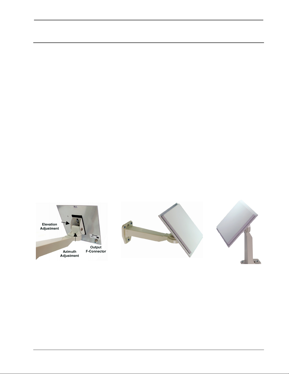
Elevation and
Azimuth Adjustments
Wall Mounting
Attach the wall mount assembly to a flat surface. Use the supplied screws to secure
the mount in the position desired (use of the included anchors requires 5/16” holes).
Horizontal Mount
Vertical Mount
Installation Guide – DOC. 6723A Antenna System: SRD-ANT-4-PAK • 5
Page 10

Antenna System Crestron SRD-ANT-4-PAK
Pole Mounting
Attach the antenna to any pole (not larger than two inches in diameter) using the
U-bolt and saddle with supplied attaching hardware as shown in the following
figures.
U-Bolt
NOTE: For operation in close proximity to high power satellite radio terrestrial
repeaters, please use the supplied 20 dB attenuator on the input of the splitter to
avoid amplifier overload. Otherwise this attenuator is not required.
Saddle
Wall Mount
Bracket
Mounting Hardware 2” DirecTV Pole
1 ¾” Dish Network Pole
Hookup
After the antenna is mounted, refer to the diagram on page 2, connect cables, attach
the splitter, adjust the antenna position, and finalize the installation as follows:
1. Attach the RG-6 cable from the antenna to the splitter port labeled IN.
2. Attach an RG-6 cable from one of the OUT ports and route the cable to the
radio. (If the radio is located by the splitter, you can use the included
F-male splice).
NOTE: For best results in all configurations, use quad-shielded RG-6 cable
whenever possible.
3. Using the supplied 3-foot F-Female to SMB adapter cable, connect the
RG-6 coaxial cable from the antenna to the radio’s antenna input.
4. Adjust the azimuth and elevation pointing of the antenna for best reception
using the antenna signal strength menu in the radio. The antenna has a beam
width of ± 25º, which is narrower than standard consumer-quality home-kit
antennas, but provides higher gain and rejection to multi-path interference.
The “Appendix”, which starts on page 10, lists exact magnetic azimuth
bearings and elevation pointing angles for many major cities throughout the
US and Canada.
5. Tighten all hardware and seal the outdoor connectors using the included
weather boot or other means to prevent moisture ingress.
6 • Antenna System: SRD-ANT-4-PAK Installation Guide – DOC. 6723A
Page 11

Crestron SRD-ANT-4-PAK Antenna System
Aiming the Antenna
Refer to the documentation supplied with the tuner/radio for information on
observing signal strength. Adjust the antenna as required to maximize the signal.
XM Reception
XM has two satellites located in fixed orbital positions in the southern sky (at 115°
W longitude and 85º W longitude). These satellites each carry all of the XM
channels, so it is only required to have an un-obscured line-of-sight to one of these
orbital locations.
Initially set up the antenna with its orientation approximately due south, at an up
elevation angle of approximately 45º. Use this as the starting spot and peak the signal
reception for maximum on one of the XM satellites using the antenna alignment
menu in the radio. The “Appendix” lists exact magnetic azimuth bearings and
elevation pointing angles for many major cities throughout the US and Canada.
SIRIUS Reception
SIRIUS has three satellites in elliptical orbits that are constantly moving over the
earth in a “figure 8”. These orbits are arranged so that two satellites are always in
view at any point in time at relatively high elevation angles (from + 45° to almost
90°) in the sky. Your antenna should be aimed at the “cross-over point” of the
“figure 8”, or about 96.5° West Longitude and 46° North Latitude.
The table and figure below provide relative azimuth pointing guidelines for the
United States and Canada. Your antenna should be aimed for the “X” in the figure.
The “Appendix” lists exact magnetic azimuth bearings and elevation pointing angles
for many major cities throughout the US and Canada. Since the satellites’ positions
are constantly changing, signal strength will vary somewhat at different times of the
day.
SIRIUS Antenna Aiming Guidelines
AREA* ANTENNA AIMING DIRECTION NORTH AMERICA
AREA 1 Aim the antenna EAST, NORTHEAST, or SOUTHEAST
AREA 2 Aim the antenna NORTH or NORTHEAST
AREA 3 Aim the antenna NORTH or NORTHWEST
AREA 4 Aim the antenna WEST or NORTHWEST
AREA 5 Aim the antenna STRAIGHT UP at the sky
* Refer to the following illustration for approximate area definitions.
SIRIUS Antenna Aiming Areas, North America
Installation Guide – DOC. 6723A Antenna System: SRD-ANT-4-PAK • 7
Page 12

Antenna System Crestron SRD-ANT-4-PAK
Problem Solving
Troubleshooting
The table after this paragraph provides corrective action for possible trouble
situations. If further assistance is required, please contact a Crestron customer
service representative.
SRD-ANT-4-PAK Installation Troubleshooting
TROUBLE POSSIBLE
No signal reception. Radio
display shows:
“Antenna Disconnected”, or
“Acquiring Signal”
“Check Antenna” or “No
Signal”
Limited reception or
channels available for XM
and/or SIRIUS tuners.
CAUSES
Short circuits
or
discontinuities
Antenna is
connected
properly but
signal is too
weak for
reception.
Problem with
tuner card.
CORRECTIVE ACTION
With radio on and all antenna
cables connected at the radio,
check for 4 - 7 VDC at antenna
end of cable.
With radio on and all antenna
cables connected at the radio,
check for AC voltage at
antenna end of cable; should
be < 1 VAC. If AC voltage is
found, check for ground loops.
Ensure proper cable type and
length(s) per the illustration on
page 2.
Ensure amplifiers are oriented
properly with the output
(marked with an arrow labeled
Radio) oriented towards the
radio.
Refer to the instructions
supplied with the antenna to
ensure the antenna is pointed
accurately.
Ensure that the tuner card is
registered/activated.
Further Inquiries
If you cannot locate specific information or have questions after reviewing this
guide, please take advantage of Crestron's award winning customer service team by
calling Crestron at 1-888-CRESTRON [1-888-273-7876].
You can also log onto the online help section of the Crestron website
(www.crestron.com/onlinehelp
users will need to establish a user account to fully benefit from all available features.
8 • Antenna System: SRD-ANT-4-PAK Installation Guide – DOC. 6723A
) to ask questions about Crestron products. First-time
Page 13

Crestron SRD-ANT-4-PAK Antenna System
Future Updates
As Crestron improves functions, adds new features and extends the capabilities of
the SRD-ANT-4-PAK, additional information may be made available as manual
updates. These updates are solely electronic and serve as intermediary supplements
prior to the release of a complete technical documentation revision.
Check the Crestron website periodically for manual update availability and its
relevance. Updates are identified as an “Addendum” in the Download column.
Installation Guide – DOC. 6723A Antenna System: SRD-ANT-4-PAK • 9
Page 14

Antenna System Crestron SRD-ANT-4-PAK
Appendix: Azimuth and Elevation Pointing Guide
The following chart shows the optimum azimuth bearing and elevation pointing
angles for locations throughout the US (below) and Canada (starting on page 12).
The azimuth has been magnetically corrected.
NOTE: Although in many locations it may be possible to receive signals from
terrestrial repeaters, it is not recommended to use these signals at fixed locations.
Repeater signal strength can vary greatly from day to day as a function of many
uncontrolled variables.
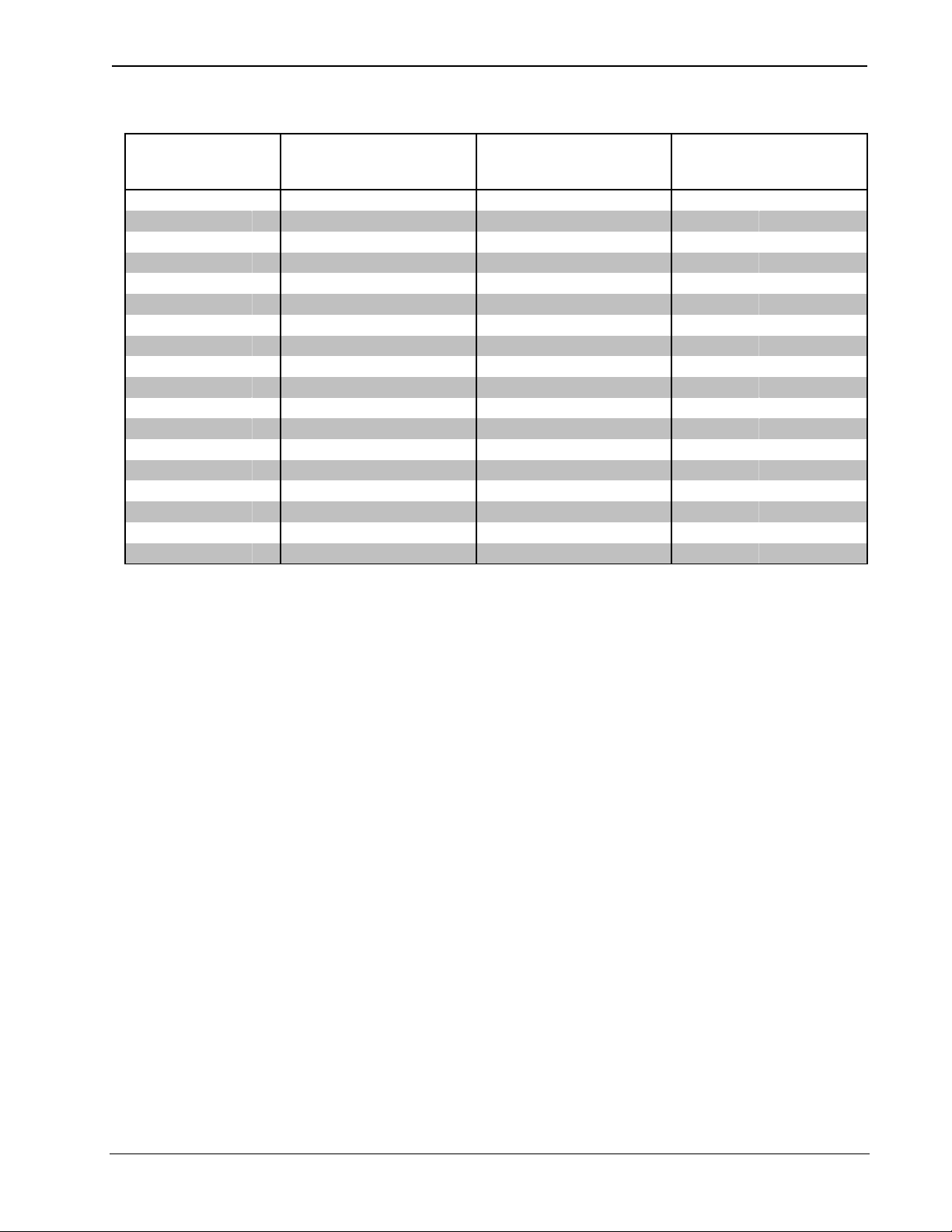
SIRIUS and XM Satellite Azimuth and Elevation Angle Settings - US
SIRIUS XM SAT 1 (WEST 85°) XM SAT 2 (WEST 115 °)
CITY ST AZIMUTH° ELEVATION° AZIMUTH° ELEVATION° AZIMUTH° ELEVATION°
Birmingham AL 324.1 71.5 179.1 49.1 223.5 39.8
Dothan AL 325.5 68.4 182.1 51.8 227.5 40.9
Little Rock AR 337.9 75.9 166.6 47.0 212.1 41.6
Phoenix AZ 40.7 66.7 128.0 40.5 173.0 49.1
Fillmore CA 50.8 60.7 119.2 35.5 160.0 47.9
Los Angeles CA 49.0 61.1 119.8 36.3 161.2 48.4
San Diego CA 45.7 61.4 120.6 38.0 163.4 50.0
San Francisco CA 58.5 58.3 116.4 30.6 153.8 43.5
Denver CO 43.8 77.6 142.4 37.9 184.4 40.8
Washington DC 300.0 65.7 202.5 42.1 239.2 29.4
Ft Myers FL 326.3 61.8 190.9 57.2 237.1 42.0
Jacksonville FL 320.9 64.9 191.3 52.7 234.8 39.2
Key West FL 328.5 59.9 191.3 59.6 238.9 43.4
Miami FL 325.2 59.9 195.4 57.9 240.5 41.4
Tampa FL 325.7 63.5 189.3 55.6 235.1 41.5
Atlanta GA 318.6 69.9 185.0 48.8 228.0 38.1
Savannah GA 317.3 65.8 192.8 50.6 234.9 37.4
Pocatello ID 355.3 70.9 131.0 31.6 169.6 38.1
Chicago IL 298.0 78.6 179.4 39.2 218.5 32.6
Dodge City KS 16.3 79.2 151.1 41.6 194.9 41.7
Kansas City KS 341.5 81.6 162.9 41.5 205.2 38.3
Louisville KY 309.3 74.5 182.7 43.5 223.4 35.0
New Orleans LA 337.0 69.8 170.1 52.9 219.5 45.0
Boston MA 293.3 60.0 214.5 36.9 247.9 23.2
Germantown MD 299.7 66.1 202.0 41.8 238.7 29.4
Caribou ME 287.4 56.8 220.2 31.3 252.0 19.0
Portland ME 291.3 59.3 216.1 35.3 248.9 21.8
Meridian MN 300.8 85.8 166.9 36.1 205.8 32.8
Minneapolis MN 285.8 86.0 167.7 35.1 206.0 31.8
(Continued on following page)
10 • Antenna System: SRD-ANT-4-PAK Installation Guide – DOC. 6723A
Page 15

Crestron SRD-ANT-4-PAK Antenna System
SIRIUS and XM Satellite Azimuth and Elevation Angle Settings - US (Continued)
US SIRIUS XM SAT 1 (WEST 85°) XM SAT 2 (WEST 115 °)
CITY ST AZIMUTH ELEVATION AZIMUTH° ELEVATION° AZIMUTH ELEVATION°
St Louis MO 319.7 78.7 172.6 42.8 214.4 36.9
Billings MT 76.2 75.9 137.9 30.4 175.6 34.5
Kalispell MT 80.8 68.9 129.1 25.8 164.8 32.0
Winston-Salem NC 308.2 67.7 195.2 45.8 234.6 33.6
Minot ND 106.5 83.7 151.7 30.0 188.7 30.6
North Platte NE 33.8 82.4 150.8 37.8 192.0 38.2
Omaha NE 349.9 84.4 160.7 38.9 201.7 36.6
Cherry Hill NJ 297.6 63.9 206.7 40.5 242.3 27.4
Albuquerque NM 33.1 72.6 137.5 41.8 183.0 46.4
Shiprock NM 41.9 72.0 134.8 39.3 178.3 44.9
Elco NV 61.0 66.7 125.7 31.9 164.4 40.5
Las Vegas NV 49.9 65.4 124.9 36.3 166.5 46.0
Reno NV 60.2 61.7 120.0 30.8 157.8 41.8
Brooklyn NY 295.9 62.8 208.9 39.5 243.7 26.2
Albany NY 292.2 63.1 209.5 37.3 243.8 24.6
Buffalo NY 290.5 69.1 199.1 37.8 235.1 27.3
New York NY 295.9 63.0 208.8 39.4 243.7 26.2
Cleveland OH 294.6 71.8 192.6 39.7 230.1 30.0
Tulsa OK 352.6 78.4 158.8 44.6 203.8 41.9
Burns OR 67.9 63.4 121.9 27.9 158.4 37.3
Eugene OR 69.0 58.9 117.1 25.3 152.1 36.2
Pendleton OR 72.4 63.9 122.6 26.2 158.3 34.8
Philadelphia PA 297.5 64.1 206.4 40.6 242.0 27.5
Newport RI 294.7 60.1 214.0 37.9 247.7 24.0
Columbia SC 313.4 67.1 193.1 48.3 234.0 35.8
Pierre SD 59.5 85.1 152.7 34.4 191.8 34.6
Nashville TN 317.6 73.8 179.8 45.9 222.2 37.4
Dallas TX 356.4 74.5 155.6 48.1 204.1 45.7
Houston TX 352.0 70.9 157.3 52.0 209.1 48.1
Lubbock TX 15.8 74.1 145.6 45.5 193.3 46.8
San Antonio TX 1.1 70.5 150.0 51.2 202.8 50.0
Salt Lake City UT 58.4 70.9 131.3 33.9 171.1 40.5
Milford UT 52.6 68.7 128.8 35.6 169.9 43.4
Norfolk VA 304.1 64.1 204.1 44.3 241.2 30.5
Burlington VT 288.9 62.7 210.8 35.1 244.5 22.9
Seattle WA 75.0 59.8 118.3 22.8 152.5 32.3
Green Bay WI 283.3 79.9 179.3 36.2 217.1 30.3
Milwaukee WI 291.9 79.3 179.1 37.9 217.6 31.6
Charleston WV 303.8 70.4 192.2 43.3 231.2 32.6
Casper WY 61.3 77.9 141.0 34.1 180.7 37.5
Installation Guide – DOC. 6723A Antenna System: SRD-ANT-4-PAK • 11
Page 16
Antenna System Crestron SRD-ANT-4-PAK
SIRIUS and XM Satellite Azimuth and Elevation Angle Settings - Canada
CANADA SIRIUS XM SAT 1 (WEST 85°) XM SAT 2 (WEST 115 °)
CITY PR AZIMUTH° ELEVATION° AZIMUTH° ELEVATION° AZIMUTH° ELEVATION°
Vancouver BC 78.4 58.7 115.9 22.9 151.3 33.0
Prince Rupert BC 81.4 49.7 108.0 15.9 140.6 26.5
Calgary AB 89.7 68.6 128.6 25.5 165.3 31.5
Edmonton AB 129.7 68.3 162.3 23.5 198.2 28.8
Saskatoon SK 109.0 76.0 141.4 27.0 178.6 29.9
Toronto ON 287.9 69.8 198.6 39.3 236.5 28.4
Ottawa ON 282.6 65.6 204.0 36.9 240.1 25.1
Montreal QB 286.3 63.2 210.9 36.4 246.1 23.8
St Johns QB 286.8 62.8 211.5 36.6 246.6 23.7
Halifax NS 290.7 51.7 227.8 34.3 259.4 18.1
Saint John's NF 288.2 39.4 240.4 27.1 268.6 9.7
Brandon MT 131.5 83.9 154.3 31.1 193.0 31.1
Sault Sainte Marie ON 274.9 75.7 188.3 36.5 226.7 28.7
Thunder Bay ON 255.0 80.9 177.8 34.3 216.3 29.1
Whitehorse YT 84.2 42.8 102.7 9.8 133.9 19.2
Winnipeg MA 165.3 85.4 159.3 31.7 197.9 30.4
Yellowknife NT 110.9 61.7 127.2 15.3 160.3 19.3
Vancouver BC 78.4 58.7 115.9 22.9 151.3 33.0
12 • Antenna System: SRD-ANT-4-PAK Installation Guide – DOC. 6723A
Page 17

Crestron SRD-ANT-4-PAK Antenna System
Return and Warranty Policies
Merchandise Returns / Repair Service
1. No merchandise may be returned for credit, exchange or service without prior authorization
from CRESTRON. To obtain warranty service for CRESTRON products, contact an
authorized CRESTRON dealer. Only authorized CRESTRON dealers may contact the factory
and request an RMA (Return Merchandise Authorization) number. Enclose a note specifying
the nature of the problem, name and phone number of contact person, RMA number and
return address.
2. Products may be returned for credit, exchange or service with a CRESTRON Return
Merchandise Authorization (RMA) number. Authorized returns must be shipped freight
prepaid to CRESTRON, 6 Volvo Drive, Rockleigh, N.J. or its authorized subsidiaries, with
RMA number clearly marked on the outside of all cartons. Shipments arriving freight collect
or without an RMA number shall be subject to refusal. CRESTRON reserves the right in its
sole and absolute discretion to charge a 15% restocking fee plus shipping costs on any
products returned with an RMA.
3. Return freight charges following repair of items under warranty shall be paid by CRESTRON,
shipping by standard ground carrier. In the event repairs are found to be non-warranty, return
freight costs shall be paid by the purchaser.
CRESTRON Limited Warranty
CRESTRON ELECTRONICS, Inc. warrants its products to be free from manufacturing defects in materials
and workmanship under normal use for a period of three (3) years from the date of purchase from
CRESTRON, with the following exceptions: disk drives and any other moving or rotating mechanical
parts, pan/tilt heads and power supplies are covered for a period of one (1) year; touchscreen display and
overlay components are covered for 90 days; batteries and incandescent lamps are not covered.
This warranty extends to products purchased directly from CRESTRON or an authorized CRESTRON
dealer. Purchasers should inquire of the dealer regarding the nature and extent of the dealer's warranty, if
any.
CRESTRON shall not be liable to honor the terms of this warranty if the product has been used in any
application other than that for which it was intended or if it has been subjected to misuse, accidental
damage, modification or improper installation procedures. Furthermore, this warranty does not cover any
product that has had the serial number altered, defaced or removed.
This warranty shall be the sole and exclusive remedy to the original purchaser. In no event shall
CRESTRON be liable for incidental or consequential damages of any kind (property or economic damages
inclusive) arising from the sale or use of this equipment. CRESTRON is not liable for any claim made by a
third party or made by the purchaser for a third party.
CRESTRON shall, at its option, repair or replace any product found defective, without charge for parts or
labor. Repaired or replaced equipment and parts supplied under this warranty shall be covered only by the
unexpired portion of the warranty.
Except as expressly set forth in this warranty, CRESTRON makes no other warranties, expressed or
implied, nor authorizes any other party to offer any warranty, including any implied warranties of
merchantability or fitness for a particular purpose. Any implied warranties that may be imposed by law are
limited to the terms of this limited warranty. This warranty statement supersedes all previous warranties.
Trademark Information
All brand names, product names and trademarks are the sole property of their respective owners. Windows is a registered trademark
of Microsoft Corporation. Windows95/98/Me/XP/Vista and WindowsNT/2000 are trademarks of Microsoft Corporation.
Installation Guide – DOC. 6723A Antenna System: SRD-ANT-4-PAK • 13
Page 18

Antenna System Crestron SRD-ANT-4-PAK
This page is intentionally left blank.
14 • Antenna System: SRD-ANT-4-PAK Installation Guide – DOC. 6723A
Page 19

Crestron SRD-ANT-4-PAK Antenna System
This page is intentionally left blank.
Installation Guide – DOC. 6723A Antenna System: SRD-ANT-4-PAK • 15
Page 20

Crestron Electronics, Inc. Installation Guide – DOC. 6723A
15 Volvo Drive Rockleigh, NJ 07647 (2021911)
Tel: 888.CRESTRON 08.08
Fax: 201.767.7576 Specifications subject to
www.crestron.com change without notice.
 Loading...