

Page 1
CEN-NVS100
(4) Drywall Screws,
(Not Supplied)
Rack Mount Screws
(Not Supplied)
P = (For factory use only)
C = Common
I = Digital Input
O = Digital Output
+ = RS-485, T+/R+
– = RS-485, T-/R-
12V DIO 485
P C I O +
–
(4) Screws, M3 x 5mm
Phillips Flat Head
(Supplied)
Mounting Bracket
Network Video Streamer
ediug tratskciuq
1
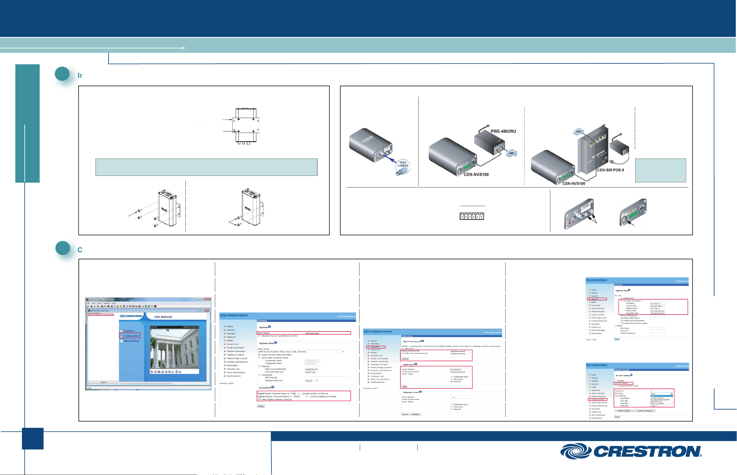
Installing the CEN-NVS100
MOUNTING
A. Attach the Supplied Mounting Bracket.
B. Mount the CEN-NVS100 to a Wall or to a Rack.
NOTE: The CEN-NVS100 must be installed in a temperature-controlled environment ranging from
32° to 104° F (0° to 40° C).
Wall Mounting: Rack Mounting:
Mount the left or right side
of the bracket to the front or
rear rail of a rack (mounting of
right side of bracket is shown).
CONNECTIONS
(Front) Video Connection
If necessary, use the supplied
BNC-to-RCA adapter to connect
to the camera.
(Rear, Optional) 6-pin Terminal Block Connection
Using the supplied terminal block mating connector,
connect the 6-pin terminal block to external devices
such as an alarm, sensor, and PTZ camera.
(Rear) Power over Ethernet (PoE) Connection
Connection to Crestron® PoE Injector
(Part No. PWE-4803RU)
Connection to Crestron PoE Switch
(Part No. CEN-SW-POE-5 Shown)
For Future or Factory Use Only
(For Future Use)
Connection to
Third-Party PoE
Power Source.
For installation
information, refer to
the third-party device
documentation.
NOTE: By default,
the CEN-NVS100
uses DHCP.
(For Factory Use Only)
2
Configuring the CEN-NVS100
A. Access the Configuration Web Pages.
1. In the Device Discovery Tool of Crestron Toolbox™,
select Crestron CEN-NVS100. The home page of the
CEN-NVS100 opens.
CEN-NVS100 Home Page (Default)
2. Select Configuration. The “System” configuration page
opens (refer to Step B).
B. (Optional) Configure System Settings.
1. On the “System” configuration page, modify the default host
name, CEN-NVS100, using a name that is meaningful for
your environment.
2. Configure DI (Digital Input) and DO (Digital Output) settings.
3. Click Save.
“System” Configuration Page
C. Configure Security Settings.
1. Click Security. The “Security” configuration page opens.
2. In the Root Password pane, assign an administrator password
and then click Save at the bottom of the pane. A log-in
window appears.
3. Enter root as the user name, and then enter the password you
entered in step 2.
4. In the Add User pane, create a user account whose user type
is set to Viewer, and then click Add.
“Security” Configuration Page
D. Configure Network Settings.
1. Click Network. The “Network”
configuration page opens.
2. Configure a static IP
address and related
network information.
3. Click Save.
E. (Optional) Configure Camera Control Settings.
1. Click Camera Control.
The “Camera Control”
configuration page opens.
2. Click PTZ Camera,
and then configure
the camera settings
as required.
3. Click Save.
“Network” Configuration Page
“Camera Control” Configuration Page
CEN-NVS100
1
QUICKSTART DOC. 6746A (2022586) 03.09
www.crestron.com
©2009 Specifications subject to
change without notice.
888.273.7876 201.767.3400
All brand names, product names and trademarks
are the property of their respective owners.
Page 2
CEN-NVS100
Network Video Streamer
ediug tratskciuq
3
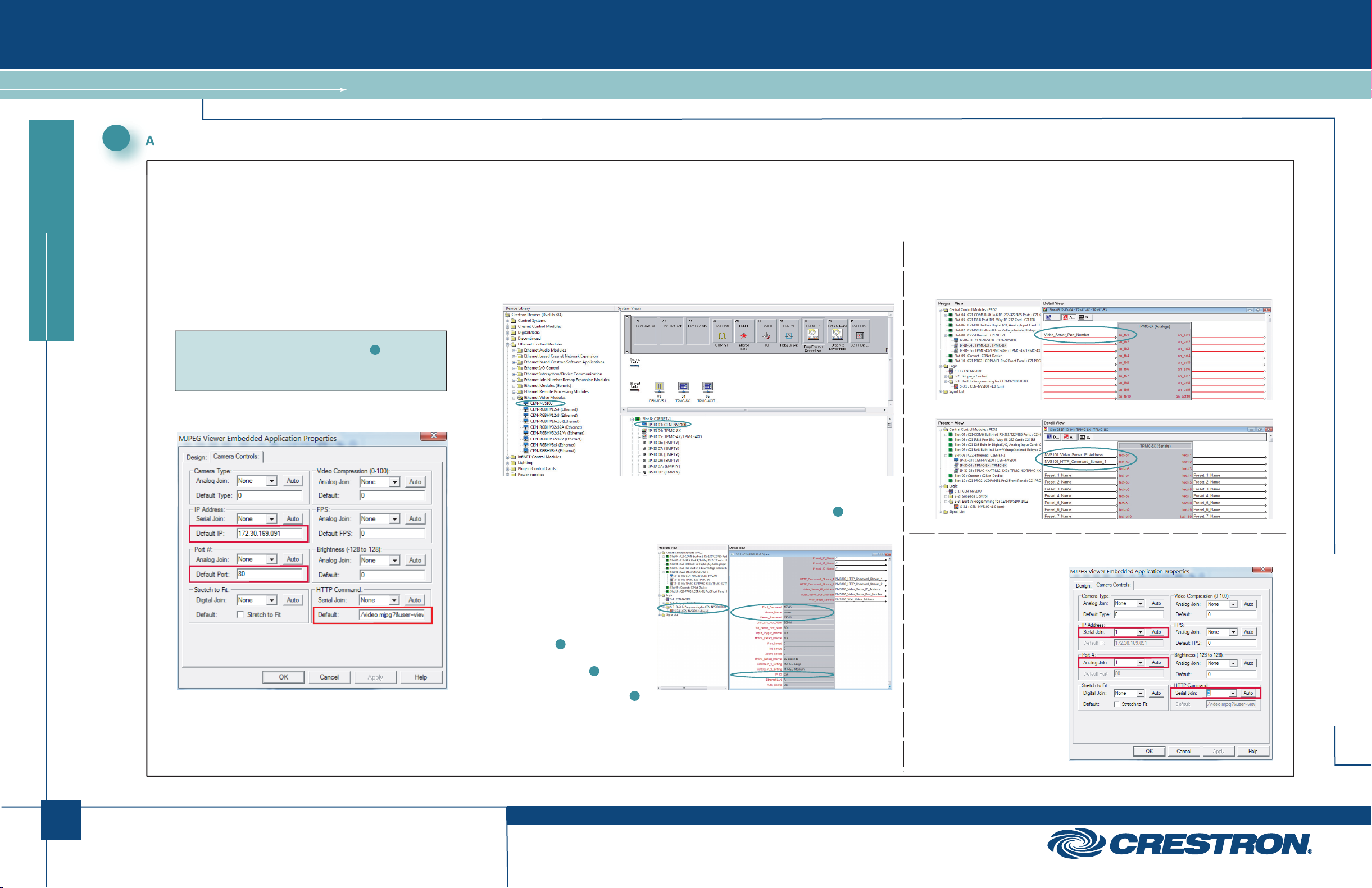
Adding the CEN-NVS100 to Your Crestron System
To add the CEN-NVS100 to your Crestron system, perform the steps in Option 1 or Option 2:
● Option 1 uses VisionTools® Pro-e (VT Pro-e) programming and provides streaming video capabilities only.
● Option 2 uses both SIMPL Windows and VT Pro-e programming and provides the following capabilities: streaming video, touchpanel control of PTZ cameras, control system response for digital I/O, motion detection, and video detection.
Option 1: VT Pro-e Programming Only
A. For the desired touchpanel in the ProjectView tab, open the Embedded
Applications folder and then double-click MJPEG Viewer to open the
“MJPEG Viewer Embedded Application Properties” window.
B. Click the Camera Controls tab.
C. Enter the IP address, port number, and HTTP command into the
appropriate fields, and then click OK.
NOTE: For the HTTP command, enter the viewer name and viewer password
assigned when creating a Viewer user account in section , step C4 of
this guide. For example, if the viewer name is MyViewer and the password is
viewmycamera, enter the following:
/video.mjpg?user=MyViewer&pw=viewmycamera
D. Save the project.
“MJPEG Viewer Embedded Application Properties” Window
2
Option 2: SIMPL Windows and VT Pro-e Programming
SIMPL Windows Programming:
A. From the Ethernet Control Modules | Ethernet Video Modules folder of the Device Library,
drag the CEN-NVS100 into the System Views.
Device Library and Sample System Views
B. Double-click the CEN-NVS100 in the system tree to open the “Device Settings” window,
and then set the IP address of the CEN-NVS100 (use the IP address set in section , step D2).
If desired, also change the IP ID of the CEN-NVS100.
C. In the Logic folder of
Program View, select the
Built In Programming for
CEN-NVS100 subfolder.
D. In the Detail View, enter data
into the following text boxes:
● Root_Password (use the
root password entered
in section , step C2)
● Viewer_Name (use the name
entered in section , step C4)
● Viewer_Password (use the
password entered in section ,
step C4)
● IP_ID (use the IP ID assigned
to the CEN-NVS100)
2
2
CEN-NVS100 Module Parameters
2
2
E. Connect the CEN-NVS100 module outputs (Video_Server_Port_Number,
HTTP_Command_Stream_1, Video_Server_IP_Address, and all others required
for your application) to the touchpanel definition.
Sample TPMC-8X Port Number Analog Join
Sample TPMC-8X IP Address and HTTP Command Serial Joins
VT Pro-e Programming:
“MJPEG Viewer Embedded Application Properties” Window
A. For the desired touchpanel in
the ProjectView tab, open the
Embedded Applications folder
and then double-click
MJPEG Viewer to open the
“MJPEG Viewer Embedded
Application Properties” window.
B. Click the Camera Controls tab.
C. In the IP Address, Port #,
and HTTP Command panes,
set the join numbers using
the same numbers assigned
in step E (above) of the
“SIMPL Windows Programming”
section, and then click OK.
D. Save the project.
CEN-NVS100
2
QUICKSTART DOC. 6746A (2022586) 03.09
www.crestron.com
©2009 Specifications subject to
change without notice.
888.273.7876 201.767.3400
All brand names, product names and trademarks
are the property of their respective owners.
 Loading...