


 Loading...
Crestron C2N-TFM
FM Radio Tuner
Operations Guide

This document was prepared and written by the Technical Documentation department at:
Crestron Electronics, Inc.
15 Volvo Drive
Rockleigh, NJ 07647
1-888-CRESTRON
All brand names, product names, and trademarks are the property of their respective owners. ©2004 Crestron Electronics, Inc.
Crestron C2N-TFM |
FM Radio Tuner |
Contents
FM Radio Tuner: C2N-TFM |
1 |
Introduction ............................................................................................................................... |
1 |
Features and Functions................................................................................................ |
1 |
Specifications .............................................................................................................. |
2 |
Physical Description.................................................................................................... |
3 |
Industry Compliance ................................................................................................... |
7 |
Setup .......................................................................................................................................... |
8 |
Network Wiring........................................................................................................... |
8 |
Identity Code ............................................................................................................... |
9 |
Hardware Hookup ..................................................................................................... |
12 |
FM Tuner Example Program ................................................................................................... |
12 |
Preparation ................................................................................................................ |
13 |
Running the FM Tuner Example Program ................................................................ |
13 |
Programming Software............................................................................................................ |
15 |
Earliest Version Software Requirements for the PC ................................................. |
16 |
Programming with Crestron SystemBuilder.............................................................. |
16 |
Programming with SIMPL Windows........................................................................ |
16 |
Uploading and Upgrading ....................................................................................................... |
33 |
Communication Settings ........................................................................................... |
34 |
Uploading a SIMPL Windows Program ................................................................... |
36 |
Firmware Upgrade – FM Tuner ................................................................................ |
37 |
Firmware Upgrade – AMWX Tuner ......................................................................... |
38 |
Problem Solving ...................................................................................................................... |
40 |
Troubleshooting ........................................................................................................ |
40 |
Further Inquiries........................................................................................................ |
40 |
Future Updates .......................................................................................................... |
40 |
Appendix: RDS/RBDS Function Support ............................................................................... |
41 |
Return and Warranty Policies.................................................................................................. |
43 |
Merchandise Returns / Repair Service ...................................................................... |
43 |
CRESTRON Limited Warranty ................................................................................ |
43 |
Operations Guide - DOC. 6233A |
Contents • i |

Crestron C2N-TFM |
FM Radio Tuner |
FM Radio Tuner: C2N-TFM
Introduction
Features and Functions
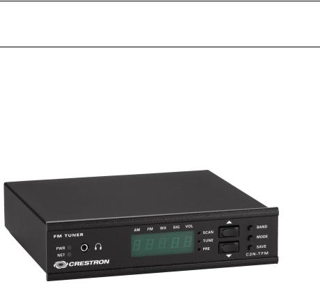
The Crestron® C2N-TFM is a Crestron-controlled FM Radio tuner (FM Tuner) designed to work stand-alone or with the companion AM/Weather band tuner, the C2N-TAMWX (AM/WX Tuner). The FM Tuner adds high-quality FM radio programming to your whole-house audio distribution system.
The FM Tuner is designed to work in a Crestron control system (Cresnet® system). You can use any Crestron multi-mode touchpanel to search through the stations and control tuner functions. The built-in RDS/RBDS feature permits display of digital data, such as program type, clock time, traffic announcements, etc., that may be transmitted along with regular FM programming. (Refer to “RDS/RBDS Feature” on page 2.) User-programmable presets let you quickly select your favorite station. Audio output from the FM Tuner can be routed to a local amplifier or to a surround sound decoder such as the C2N-DAP8 or C2N-DAP8RC. Output can also be routed to a CNX-BIPAD8 for distribution to other rooms via CAT5 cabling. (Refer also to the configuration diagram on page 12.)
Functional Summary
•Headphone connector for local monitoring of audio output
•Up to twenty presets for fast program selection
•RDS/RBDS feature for display of program types, traffic announcements, GMT-based clock time and more
•Two RCA connectors for line-level FM stereo output
•RJ-45 connector provides link (up to 500 feet) to C2N-TAMWX AM/Weather band tuner
•Integrated configuration lets local FM Tuner buttons control AM/WX Tuner
Operations Guide - DOC. 6233A |
FM Radio Tuner: C2N-TFM • 1 |
FM Radio Tuner |
Crestron C2N-TFM |
RDS/RBDS Feature
The Radio Data System (RDS), a European standard, and Radio Broadcast Data System (RBDS), a North American standard, permit broadcasters to use a sub-carrier frequency to transmit inaudible digital data along with their regular FM programming to receivers equipped to process the data.
The FM Tuner circuitry is compatible with the RDS/RBDS standards; the example program discussed later in this guide provides some typical applications of this feature, such as the display of program type name, UTC (universal time clock) data, program name and category, and traffic information. A typical benefit of this feature is the ability to search for stations based on program type.
Refer to “Appendix: RDS/RBDS Function Support” on page 41 for more information.
Mute and Mono Functions
The FM Tuner incorporates automatic as well as manual selection of mute and mono mode functions.
•The tuner can be put into mono/stereo mode or mute mode via the touchpanel.
•The tuner cannot be put into mono/stereo mode or mute mode via the tuner controls.
•After tuning to a station, the tuner will automatically switch to mono mode if the signal level is low and mono mode is off.
•The tuner automatically mutes the output during rapid scan functions.
•After tuning to a station, the radio will automatically mute if the signal level is too low and the radio-forced mono mode is off.
•The auto mute/mute feature can be disabled via the touchpanel.
Specifications
The following table summarizes the specifications for the C2N-TFM tuner.
Specifications of the C2N-TFM
|
SPECIFICATION |
DETAILS |
|
|
Power Requirements |
|
|
|
FM Tuner only |
8.0 Watts (0.3 Amp @ 24 VDC) |
|
|
FM Tuner plus AM/WX Tuner |
16.0 Watts (0.66 Amp @ 24 VDC) |
|
|
Default Net ID |
56 |
|
|
Control System Update Files 1, 2, 3 |
|
|
|
2-Series Control System |
Version 3.038.CUZ or later |
|
|
CNMSX-AV/PRO |
Version 5.12.63X.UPZ or later |
|
|
CNRACKX/-DP |
Version 5.12.63W.UPZ or later |
|
|
CEN/CN-TVAV |
Version 5.12.63V.UPZ or later |
|
|
C2N-TFM Firmware |
C2N-TFM.1.12.upg or later |
|
|
Audio Output |
|
|
|
AUDIO OUT L, R |
Two RCA connectors for line level stereo audio |
|
|
Frequency Range |
87.5 MHz to 108 MHz |
|
|
Sensitivity (Usable sensitivity mono/stereo) |
11 dBf / 60 dBf |
|
|
Maximum Signal |
100 dBf |
|
|
(continued on next page) |
|
|
|
|
|
|
2 • FM Radio Tuner: C2N-TFM |
Operations Guide - DOC. 6233A |
|
|
Crestron C2N-TFM |
|
FM Radio Tuner |
||
|
Specifications of the C2N-TFM (continued) |
|
||
|
|
|
|
|
|
SPECIFICATION |
|
DETAILS |
|
|
S/N Ratio @ 65 dBf, mono/stereo |
72 dB / 67 dB |
||
|
IF Rejection |
100 dB |
|
|
|
AM Rejection |
55 dB |
|
|
|
Stereo Separation |
40 dB |
|
|
|
Audio output level @ 1 kHzRMS |
1VRMS |
|
|
|
Output impedance |
<100 ohms single-ended |
|
|
|
Recommended load impedance |
>1K Ohm |
|
|
|
Ports/Connectors |
|
|
|
|
AM RADIO |
RJ-45 for link (up to 500 feet) to AM/Weather band tuner |
|
|
|
FM ANT |
F-Type coaxial connector for FM antenna input |
|
|
|
NET |
One 4-pin mini-terminal block connector for Cresnet® |
|
|
|
|
interface (24, Y, Z, G) |
|
|
|
Environmental temperature |
41° to 122°F (5° to 50°C) |
||
|
Humidity |
10% to 90% RH (non-condensing) |
|
|
|
Dimensions |
Height: |
1.80 in (4.57 cm) |
|
|
|
Width: |
7.07 in (17.96 cm) |
|
|
|
Depth: |
6.88 in (17.48 cm) |
|
|
Weight |
1.86 lb (0.837 kg) |
|
|
1The latest versions can be obtained from the Downloads | Software Updates section of the Crestron website (www.crestron.com). Refer to NOTE below.
2Crestron 2-Series control systems include the AV2 and PRO2. Consult the latest Crestron Product Catalog for a complete list of 2-Series control systems.
3Filenames for CNX and ST-CP update files have a UPZ extension. Files on the website may be .zip or self-extracting .exe files containing the .cuz or .upz file. All can be obtained from the Downloads section of the Crestron website. To avoid program problems, make sure you are using the update file with the correct suffix letter (e.g., S, V, W, X)
NOTE: Crestron software and any files on the website are for Authorized Crestron dealers and Crestron Authorized Independent Programmers (CAIP) only. New users may be required to register to obtain access to certain areas of the site (including the FTP site).
Physical Description
The C2N-TFM is housed in a black enclosure with labeling on the front and rear panels. The front of the unit includes ten LEDs that indicate the unit’s status, and all local controls. All connections, except for headphones, are made on the back of the unit. Four rubber feet on the bottom of the unit provide stability and prevent slippage. Refer to the figures below and on the following page.
C2N-TFM Physical Views
Operations Guide - DOC. 6233A |
FM Radio Tuner: C2N-TFM • 3 |

FM Radio Tuner |
Crestron C2N-TFM |
C2N-TFM Overall Dimensions
6.32 in
(16.05 cm)
6.88 in
(17.48 cm)
7.07 in
(17.96 cm)
FM TUNER |
AM FM WX SIG VOL |
|
|
|
SCAN |
BAND |
|
|
|
||
PWR |
TUNE |
MODE |
|
NET |
|||
PRE |
|
||
|
SAVE |
||
CRESTRON |
|
||
|
C2N-TFM |
||
|
|
NET |
|
AM RADIO |
AUDIO OUT |
FM |
|
24 Y Z |
G |
SETUP |
|
|
G |
|
|
|
|||
|
|
|
|
||
|
|
|
L |
R |
ANT |
CRESTRON E L E C T R O N I C S I N C . , R O C K L E I G H , N J 0 7 6 4 7 |
|
USA |
|||
6.94 in
(17.63 cm)
1.70 in
(4.32 cm)1.80 in
(4.57 cm)
4 • FM Radio Tuner: C2N-TFM |
Operations Guide - DOC. 6233A |
Crestron C2N-TFM |
FM Radio Tuner |
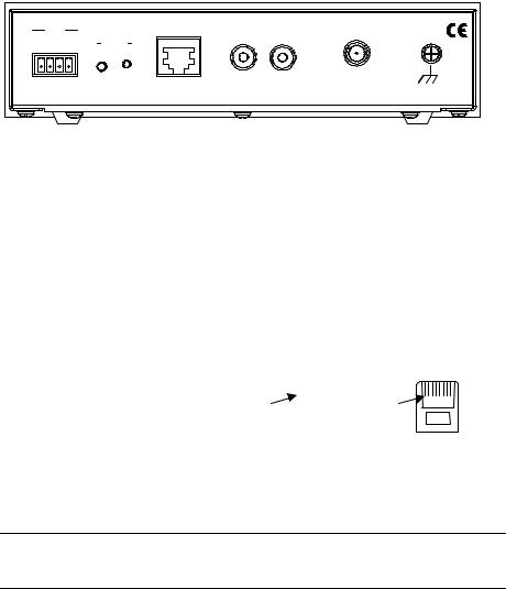
C2N-TFM Ports
All connections to the C2N-TFM, except headphones, are made through the ports on the rear panel. Refer to the illustrations and descriptions, which follow.
C2N-TFM Ports
NET |
|
AM RADIO |
AUDIO OUT |
FM |
|
24 Y Z |
G |
SETUP |
|
|
G |
|
|
|
|||
|
|
|
|
||
|
|
|
L |
R |
ANT |
CRESTRON E L E C T R O N I C S I N C . , R O C K L E I G H , N J 0 7 6 4 7 |
|
USA |
|||
NET
This 4-pin mini-terminal block connector is used to connect the C2N-TFM module to the Cresnet system. Data and power for the C2N-TFM are provided via the connection. Refer to “Network Wiring” on page 8.
AM RADIO (RJ-45)
The RJ-45 AM RADIO port provides CAT5 interface (up to 500 feet) to the companion Crestron C2N-TAMWX AM/Weather Tuner. Wiring for the connector is shown in the following diagrams.
|
PIN # |
|
SIGNAL |
|
|
|
|
|
8-PIN, RJ-45 PINOUT |
||||||||
|
|
|
|
|
|
|
|
|
|
|
|
|
|
|
|
|
|
1 |
|
|
+24V |
|
|
|
|
|
|
|
|
|
|
|
|
||
|
|
|
|
|
|
|
|
|
|
|
|
|
|
||||
|
2 |
|
|
+24V |
|
Pin 1 |
|
|
|
|
|
|
|
|
|
|
Pin 1 |
|
|
|
|
|
|
|
|
|
|
|
|
|
|
||||
3 |
|
|
COM+ |
|
|
|
|
|
|
|
|
|
|
|
|
||
|
|
|
|
|
|
|
|
|
|
|
|
|
|
||||
|
4 |
|
|
Audio+ |
|
|
|
|
|
|
|
|
|
|
|
|
|
5 |
|
|
Audio- |
RECEPTACLE, REAR VIEW |
CONNECTOR |
||||||||||||
|
6 |
|
|
COM- |
|
(TAB POSITION DOWN) |
(TAB FACING AWAY) |
||||||||||
7 |
|
|
Ground |
|
|
|
|
|
|
|
|
|
|
|
|
||
|
8 |
|
|
Ground |
|
|
|
|
|
|
|
|
|
|
|
|
|
NOTE: This connector is to be used only to provide interface to Crestron products specifically designed to work with this unit. It cannot be used for connections to Cresnet or Crestron audio distribution devices.
AUDIO OUT L, R
These two RCA connectors provide line level stereo output for local amplifiers.
FM ANT
This Type F coaxial connector is for an FM antenna cable (not supplied).
G (Chassis Ground)
Use this chassis screw to ground the unit to the amplifier and audio source common grounds.
Operations Guide - DOC. 6233A |
FM Radio Tuner: C2N-TFM • 5 |
FM Radio Tuner |
Crestron C2N-TFM |
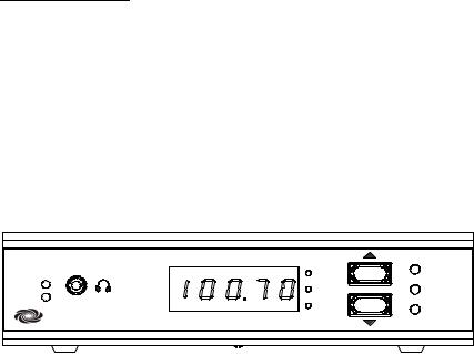
 (Headphone)
The only connection on the front panel of the FM Tuner is the mini-phone jack, which permits the use of headphones to monitor the audio signal (mono only). The volume mode, selected by the MODE switch, allows adjustment of the volume to the headphones only. Note that plugging in headphones does not interrupt the unit’s other audio output.
Front Panel Controls and Indicators
Ten LED indicators, a five-digit display, and three pushbutton switches are located on the front panel of the C2N-TFM. Refer to the illustration and descriptions that follow.
C2N-TFM Front Panel Controls and Indicators
FM TUNER |
AM FM WX SIG VOL |
|
|
|
|
||
|
SCAN |
BAND |
|
|
|
||
PWR |
TUNE |
MODE |
|
NET |
|||
PRE |
|
||
|
SAVE |
||
CRESTRON |
|
||
|
C2N-TFM |
||
|
|
PWR (Power)
This green LED illuminates when power is supplied to the C2N-TFM.
NET
This yellow LED illuminates when communication between the control system and the C2N-TFM is established (the unit is polled on the network). Illumination indicates that the program currently loaded has a network device defined at the same ID as the C2N-TFM. The LED flashes or remains on when communication with the processor occurs.
BAND Switch
Use the BAND switch to select between the AM, FM and WX (weather) bands. The corresponding red LEDs (AM, FM, WX) illuminate as each band is selected, and the five-digit display shows the appropriate values. If the AM/WX Tuner is not included in your configuration, the AM and WX modes cannot be selected.
MODE Switch, KJ (Up/Down) Buttons, and Display
Use the MODE switch to select between the signal, volume, preset, tune, and scan modes. The corresponding red LEDs (SIG, VOL, PRE, TUNE, and SCAN) illuminate as each mode is selected. In each mode, the five-digit display shows the appropriate values.
In the signal mode, the display shows a letter (d = distance mode; L = local mode) and the corresponding relative signal strength (01 through 99). The FM Tuner defaults to distance mode; when the FM signal level is too high, the program automatically switches to local mode and the signal is attenuated by 10 dB.
In the volume mode, the up/down buttons select ten volume levels (0 through 9) for the signal (mono) supplied to the headphone jack.
6 • FM Radio Tuner: C2N-TFM |
Operations Guide - DOC. 6233A |
Crestron C2N-TFM |
FM Radio Tuner |
In the preset mode, the up/down buttons let you sequence through the preset numbers (1-20) to select a station or to save a new station in a preset location.
In the tune mode, the up/down buttons let you sequence through the band frequencies in 100 kHz increments (50 kHz increments when Europe mode is enabled).
In the scan mode, the up/down buttons initiate the scan and direction of the search for the next station with a signal strong enough for good reception. Pressing either button will halt the scan.
SAVE Button
Use the SAVE button to save a station frequency in a preset location. To save a preset, select the desired station, use the MODE switch to select the preset mode, use the up/down buttons to select the preset location, and then press SAVE. The display will briefly show “SAVE” as the preset is saved.
SETUP LED and Pushbutton
The C2N-TFM is Touch Settable ID (TSID) ready. The SETUP pushbutton and its associated LED are located on the rear panel and are used for setup of the unit’s network ID during the initial configuration of a Cresnet system or when the device is being added/replaced. Refer to “Method B (Touch Settable IDs)” on page 10 for detailed information.
Industry Compliance
As of the date of manufacture, the C2N-TFM has been tested and found to comply with specifications for CE marking and standards per EMC and Radiocommunications Compliance Labelling.
NOTE: This device complies with part 15 of the FCC rules. Operation is subject to the following two conditions: (1) these devices may not cause harmful interference, and (2) these devices must accept any interference received, including interference that may cause undesired operation.
Operations Guide - DOC. 6233A |
FM Radio Tuner: C2N-TFM • 7 |
FM Radio Tuner |
Crestron C2N-TFM |
Setup
Network Wiring
CAUTION: Use only Crestron power supplies for Crestron equipment. Failure to do so could cause equipment damage or void the Crestron warranty.
CAUTION: Provide sufficient power to the system. Insufficient power can lead to unpredictable results or damage to the equipment. Please use the Crestron Power Calculator to help calculate how much power is needed for the system. http://www.crestron.com/dealer-tech_resources/power_calculator.asp
NOTE: When installing network wiring, refer to the latest revision of the wiring diagram(s) appropriate for your specific system configuration, available from the Downloads | Product Manuals | Wiring Diagrams section of the Crestron website (www.crestron.com).
When calculating the wire gauge for a particular Cresnet run, the length of the run and the power factor of each network unit to be connected must be taken into consideration. If Cresnet units are to be daisy-chained on the run, the power factor of each unit to be daisy-chained must be added together to determine the power factor of the entire chain. If the unit is a home-run from a Crestron system power supply network port, the power factor of that unit is the power factor of the entire run. The length of the run in feet and the power factor of the run should be used in the resistance equation below to calculate the value on the right side of the equation.
Resistance Equation
R < 40,000 L x PF
Where: R |
= |
Resistance (refer to table below). |
L |
= |
Length of run (or chain) in feet. |
PF = Power factor of entire run (or chain).
The required wire gauge should be chosen such that the resistance value is less than the value calculated in the resistance equation. Refer to the following table.
Wire Gauge Values
RESISTANCE |
WIRE GAUGE |
|
|
4 |
16 |
6 |
18 |
10 |
20 |
15 |
22 |
13 |
Doubled CAT5 |
8.7 |
Tripled CAT5 |
NOTE: All Cresnet wiring must consist of two twisted pairs. One twisted pair is the +24V conductor and the GND conductor, and the other twisted pair is the Y conductor and the Z conductor.
NOTE: When daisy-chaining Cresnet units, strip the ends of the wires carefully to avoid nicking the conductors. Twist together the ends of the wires that share a pin on the network connector, and tin the twisted connection. Apply solder only to the ends of the twisted wires. Avoid tinning too far up the wires or the end becomes brittle. Insert the tinned connection into the Cresnet connector and tighten the retaining screw. Repeat the procedure for the other three conductors.
8 • FM Radio Tuner: C2N-TFM |
Operations Guide - DOC. 6233A |

Crestron C2N-TFM |
FM Radio Tuner |
Refer to the note on page 33 for a definition of Viewport.
Identity Code
Every equipment and user interface within the network requires a unique identity code (Net ID). These codes are two-digit hexadecimal numbers from 03 to FE. The Net ID of each unit must match an ID code specified in the SIMPL Windows program. Refer to “Setting the Net ID in Device Settings” on page 18 for details of the SIMPL Windows procedure.
The Net ID of the C2N-TFM has been factory set to 56. The Net IDs of multiple C2N-TFMs in the same system must be unique. Net IDs are changed from a personal computer (PC) via the Crestron Viewport.
NOTE: For detailed information on establishing communication between the PC and control system, refer to “Communication Settings” on page 34. If communication cannot be established, refer to the “Troubleshooting Communications” section in the respective Operations Guide for the control system.
There are two different methods—Method A or Method B—for setting the C2NTFM Net IDs:
Method A (Cresnet address-settable ID), described below, applies to C2N-TFMs in a Cresnet system with a CNX control system or with a 2-Series control system upgrade file (CUZ) version prior to 3.008, but can be used with later versions of firmware and requires that a single unit be the only network device connected to the control system.
Method B (Touch Settable IDs), which begins on the next page, applies to C2NTFMs in a Cresnet system with 2-Series control system upgrade file (CUZ) version 3.029 or later. These upgrades enable Touch Settable ID (TSID) functionality, which makes it possible for the control system to recognize a network device via its serial number, which is stored in the device’s memory. This method does not require that any devices be disconnected from the network; Net IDs may be set with the entire Cresnet system intact. This method requires the use of the Crestron Viewport version 3.35 or later.
Use the appropriate method to set the C2N-TFM Net ID.
Method A (Cresnet address-settable ID)
1.Ensure that the C2N-TFM is the only device connected to the control system.
2.Open the Crestron Viewport.
3.From the Viewport menu, select Functions | Set Network ID. The software checks the baud rate and then opens the "Set Network ID" window.
4.In the "Set Network ID" window, select the C2N-TFM from the
Current Network Devices text window.
5.Select the new Net ID for the C2N-TFM from the Choose the new network ID for the selected device (Hex): text box.
6.Click Set ID to initiate the change. This will display the "ID command has been sent" window.
7.In the "Command Complete" window, click OK.
8.In the Current Network Devices text window, verify the new Net ID code.
Operations Guide - DOC. 6233A |
FM Radio Tuner: C2N-TFM • 9 |
FM Radio Tuner |
Crestron C2N-TFM |
9.In the "Set Network ID" window, click Close.
NOTE: The new Net ID code may also be verified by selecting Diagnostic |
Report Network Devices in the Viewport (alternately, select F4).
10. Repeat this procedure for each C2N-TFM to be added to the system.
Method B (Touch Settable IDs)
Before using this method, you should have a list of all current network devices and their Net IDs, to avoid assigning duplicate IDs.
Set Net ID by TSID
These procedures are for TSID-enabled network devices during the initial configuration of a Cresnet system or when such devices are being added/replaced.
1.Ensure that all C2N-TFMs are connected to the control system.
2.Open the Crestron Viewport version 3.35 or later.
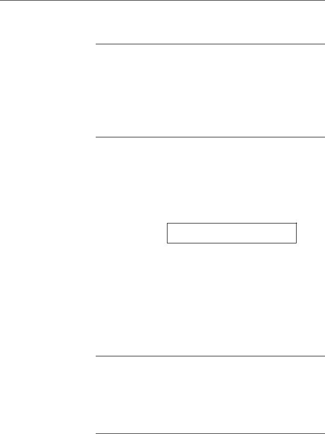
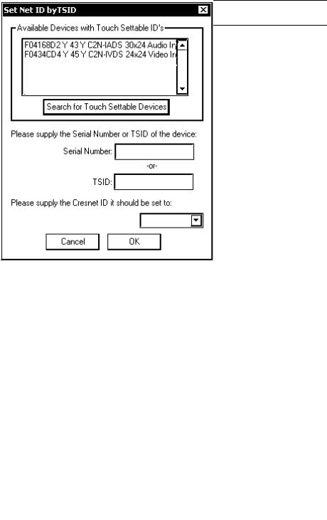
3.From the Viewport menu, select Functions | Assign Cresnet ID by Serial Number. The “Set Net ID by TSID” window appears. The window is first displayed with the data fields empty. (Refer to the following figure.)
“Set Net ID by TSID” Window
4.Click on the Search for Touch Settable Devices button. The system searches the network and lists all TSID-enabled devices found. The list is similar to the report produced by pressing F4 (Report Network Devices); the first eight digits of each line constitute the TSID number (hexadecimal form of the serial number).
10 • FM Radio Tuner: C2N-TFM |
Operations Guide - DOC. 6233A |
Crestron C2N-TFM |
FM Radio Tuner |
5.As you enter either the serial number or TSID number of the device that requires a change, the corresponding TSID or serial number automatically appears in its appropriate field, and the list scrolls to and highlights the device listing. The listing should show the device’s current Cresnet ID.
6.Enter the Cresnet ID that the device should be set to and click OK. The number you enter should appear on the list.
CAUTION: This function does not prevent you from setting duplicate IDs. Be sure to check current assignments before entering the desired Cresnet ID number.
Serial Number to TSID Conversion
This utility is useful in a case where there are multiple devices of the same type on a network, you need to locate a particular one, you know the TSID but not the serial number, and your site installation list is based on device serial numbers. In this (or the reverse) situation, do the following:
1.Open the Crestron Viewport.
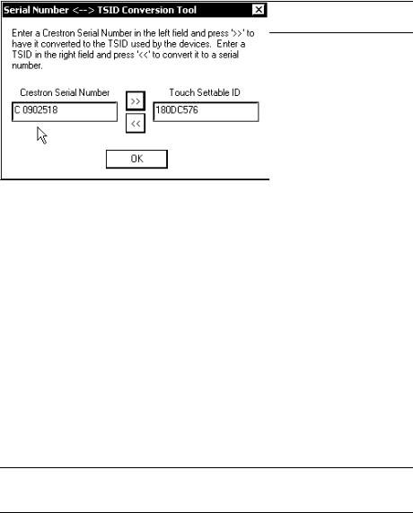
2.From the Viewport menu, select Functions | Serial Number ÅÆ TSID Conversion Tool. The “Serial Number ÅÆTSID Conversion Tool” window is displayed. (Refer to the following figure.)
“Serial Number to TSID Conversion Tool” Window
3.Enter the serial number or TSID number as instructed; press the appropriate button to obtain the corresponding number.
NOTE: Enter serial numbers, including spaces, exactly as they appear on the unit label. Alpha characters in serial numbers or TSID numbers may be entered in upper or lower case.
Operations Guide - DOC. 6233A |
FM Radio Tuner: C2N-TFM • 11 |
Loading...