

Crestron ZUMNET-JBOX-16A-LV, ZUMNET-JBOX-DALI, ZUMLINK-JBOX-16A-LV, ZUMLINK-JBOX-20A-SW, ZUMLINK-JBOX-20A-PLUG User guide
Page 1
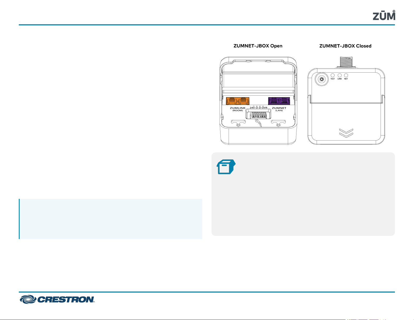
ZUMNET-JBOX Series
Zūm® Wired J-Box Load Controller with Net and Link Communication
The Crestron® ZUMNET-JBOX-16A-LV and ZUMNET-JBOX-DALI load
controllers:
l
Provide a sophisticated, wired lighting control solution for Zūm®
commercial lighting systems.
l
Facilitate communication between rooms via the
CBL-CAT5E-ZUMNET-P cables (sold separately) for daisy-chained
network expansion.
l
Connect to Zūm Link devices for in-room communication.
l
Mount directly to a 4in. square junction box.
The ZUMNET-JBOX-16A-LV and ZUMNET-JBOX-DALI load controllers
are functionally similar. For simplicity within this guide, the term
"ZUMNET-JBOX" is used except where otherwise noted.
For more information about the Zūm Net and Zūm Link load controllers
for wired applications, refer to the following product pages:
l
ZUMNET-JBOX-16A-LV: 0-10V Dimmer, 16A, 100-277V
l
ZUMNET-JBOX-DALI: DALI® Load Controller, 100-277V
l
ZUMLINK-JBOX-16A-LV: 0-10V Dimmer, 16A, 100-277V
l
ZUMLINK-JBOX-20A-SW: High Inrush Switch, 20A, 100-277V
l
ZUMLINK-JBOX-20A-PLUG: Plug Load Switch, 20A, 100-240V
NOTE: ZUMLINK-JBOX devices allow for in-room lighting control
through compatible keypads and sensors. Two RJ-45 ports on the
device and the CBL-CAT5E-ZUMNET-P cables (sold separately)
allow for connection to a Zūm Net device and for in-room device
daisy-chaining.
In the Box
1
5 Yellow Wire Nut, 22-10 AWG (2049245)
1 Locknut (2047626)
1 Tie Wrap (2005429)
ZUMNET-JBOX-16A-LV or ZUMNET-JBOX-DALI, Zūm®
NET Wired J-Box Load Controller
Additional Items
1
Page 2
ZUMNET-JBOX Series
Zūm® Wired J-Box Load Controller with Net and Link Communication
NOTES:
l
Installation
WARNINGS:
l
To avoid fire, shock, or death, turn off the power at the circuit
breaker or fuse and test that the power is off before wiring!
l
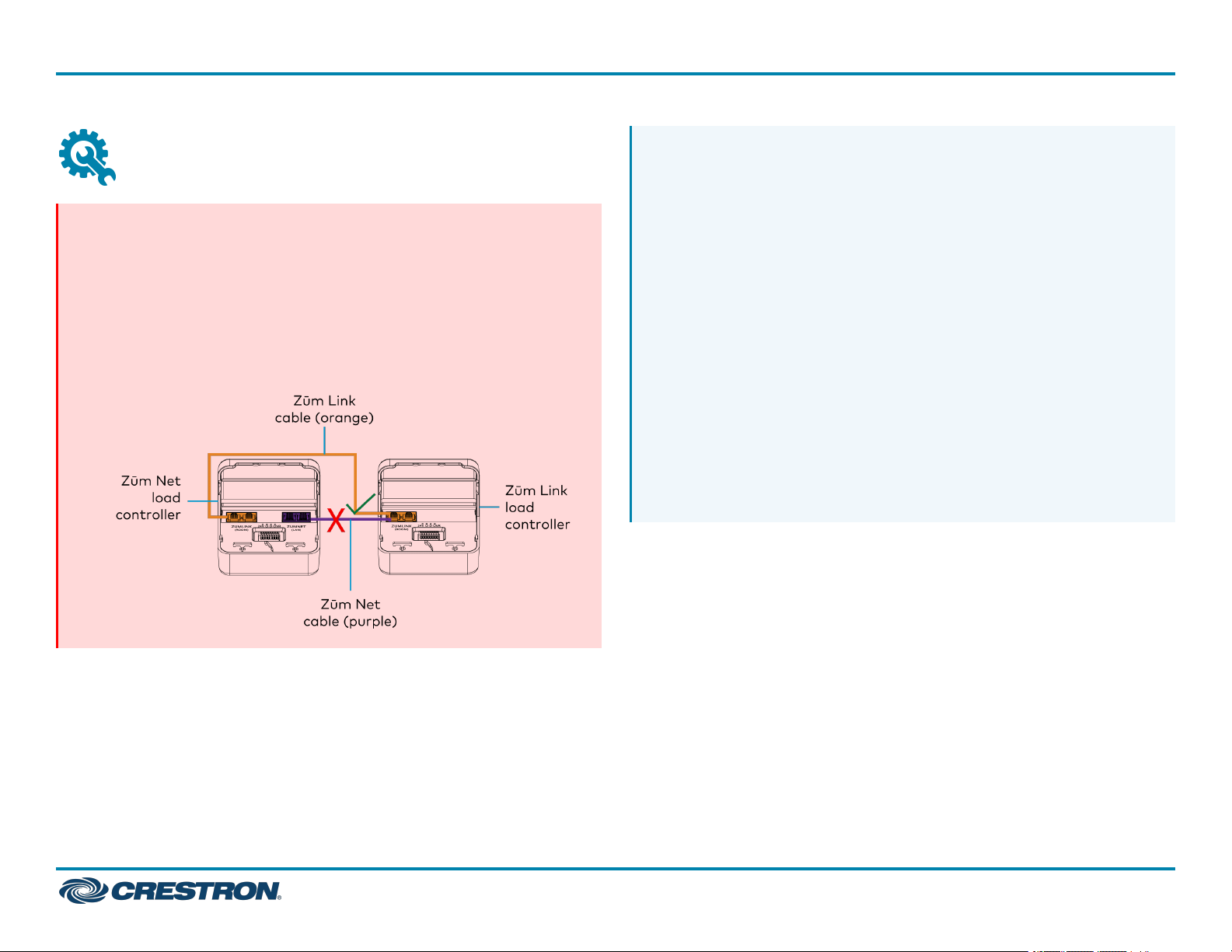
Do NOT connect standard Ethernet ports on network-based
devices to the orange Zūm Link ports on any Zūm Link or Zūm
Net device. Also, do NOT connect the purple Zūm Net ports on
the Zūm Net device to the orange Zūm Link ports on any Zūm
Link device. These connections may damage network devices.
Install and use this product in accordance with appropriate
electrical codes and regulations.
l
A licensed electrician should install this product.
l
The product should project 4.40in. (112mm) from the junction
box when installed.
l
For use where temperatures are between 32° to 104°F (0° to
40°C)
l
For Chicago plenum compliant installations:
o
Ensure that the junction boxes and other electrical
components are rated for Chicago plenum.
o
Separate the high-voltage lines from the low-voltage cables.
o
Install two junction boxes: one junction box for the highvoltage lines and one junction box for the low-voltage cables
and load controller. A 6 in. square, 3.5 in. deep box with
conduit knockouts is recommended for the low-voltage cables
and load controller.
QuickStart
2
Page 3
ZUMNET-JBOX Series
Zūm® Wired J-Box Load Controller with Net and Link Communication
QuickStart
To install a load controller:
1. Turn the power off at the circuit breaker.
2. Mount the load controller to the junction box using the included
locknut.
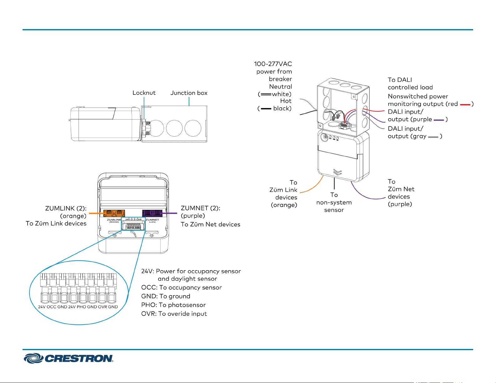
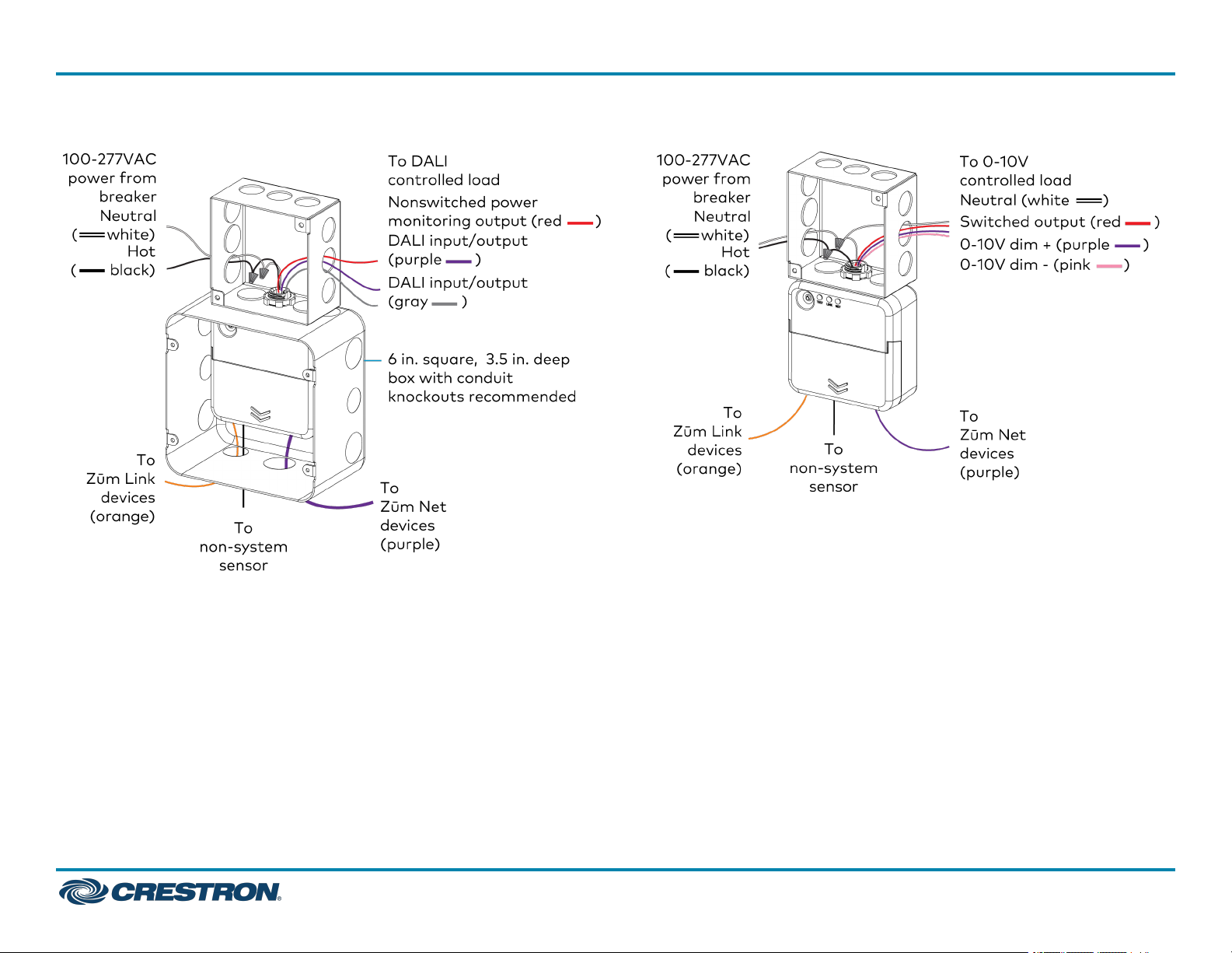
3. Wire the load controller as shown in the following diagrams.
Zūm Net Load Controller Wiring to Other Zūm Net and Zūm Link Devices
ZUMNET-JBOX-DALI Wiring
3
Page 4
ZUMNET-JBOX Series
Zūm® Wired J-Box Load Controller with Net and Link Communication
ZUMNET-JBOX-DALI Wiring to Meet Chicago Electric Code ZUMNET-JBOX-16A-LV Wiring
QuickStart
4
Page 5
ZUMNET-JBOX Series
Zūm® Wired J-Box Load Controller with Net and Link Communication
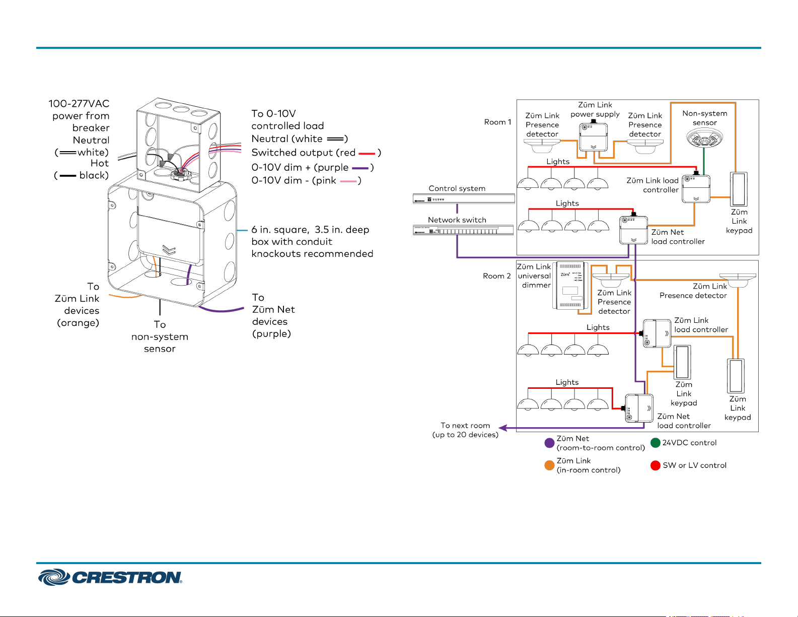
ZUMNET-JBOX-16A-LV Wiring to Meet Chicago Electric Code Zūm Wired System Diagram
QuickStart
5
Page 6
ZUMNET-JBOX Series
Zūm® Wired J-Box Load Controller with Net and Link Communication
NOTES:
l
Daisy-chain up to 20 Zūm Net devices (up to 328ft (100m)
between Zūm Net devices) with purple CBL-CAT5E-ZUMNET-P
RJ-45 cables (sold separately).
l
Do not exceed three network switches between a ZUM-HUB4
and a Zūm Net device.
l
System sensors communicate digitally via Zūm Link. Non-system
sensors communicate via an analog connection on a Zūm Wired
load controller.
Test the Loads
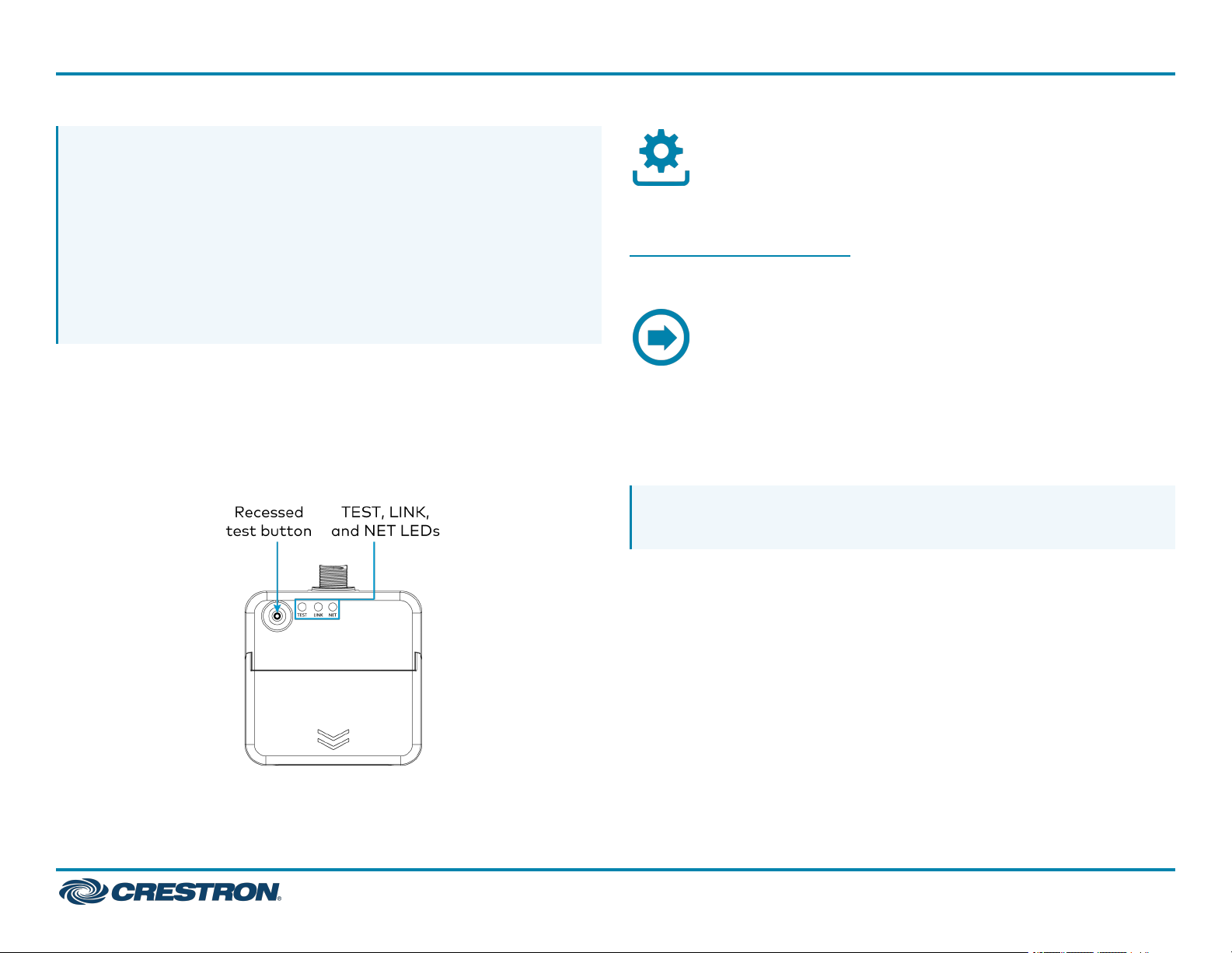
To verify system wiring, test the loads. Tap the TEST button to turn the
connected loads on and off. Press and hold the TEST button to cycle the
connected dimmers.
Zūm Net Load Controllers
Before using a Zūm Wired device, ensure it is updated with the latest
firmware. Check for the latest firmware at
www.crestron.com/firmware. Load the firmware onto the device using
Crestron Toolbox™ software, the ZUM-HUB4 web interface, or the Zūm
app (refer to Update Firmware for a Zūm Space).
A Zūm Wired space consists of at least one Zūm Net or Zūm Link load
controller connected to lights, sensors or another Zūm Wired device.
Once the devices are installed and connected together in a space, they
communicate with each other. Without any programming, the devices
behave as described below.
Firmware Upgrade
Operation
QuickStart
NOTE: To add an Zūm Wired device to an existing space, simply
connect the device and it will become part of the space logic.
6
Page 7
ZUMNET-JBOX Series
Zūm® Wired J-Box Load Controller with Net and Link Communication
QuickStart
Presence Detectors
Non-system (such as the GLA-IR-QUATTRO-HD-COM1-24 or
GLS-ODT-C-NS) and system sensors (such as the
ZUMLINK-IR-QUATTRO-DLS) will trigger and control the connected
load controller. Non-system sensors connect to the load controller via
the I/O ports, while system sensors connect to the load controller via a
CBL-CAT5E-ZUMNET-P cable.
For presence detectors with a relay (such as the
ZUMLINK-IR-QUATTRO-DLS-RLY), the default function is set to None.
Use the Zūm app to change the functionality to follow occupancy logic
or button presses.
Presence Detector Functionality When Connected to Load Controllers
Load Controller
ZUMNET-JBOX-16A-LV and
ZUMLINK-JBOX-16A-LV
ZUMLINK-JBOX-20A-SW On Recalls Scene 16
ZUMLINK-JBOX-20A-PLUG On Off after grace
Occupancy
Detected
Recalls Scene 1
(all on)
Vacancy Detected
Recalls Scene 16
(all off)
(all off)
period delay
Keypads
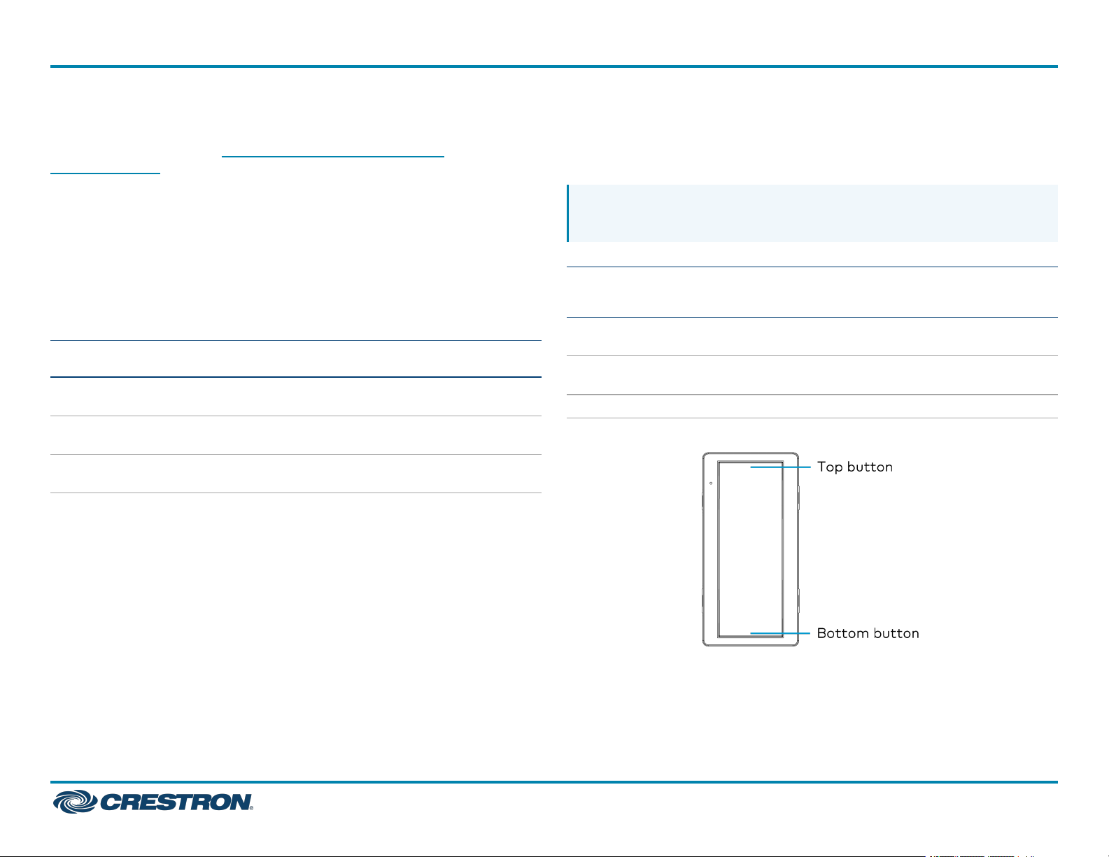
The ZUMLINK-KP-R controls most of the connected load controllers in a
space.
NOTE: The ZUMLINK-KP-R will not control a
ZUMLINK-JBOX-20A-PLUG.
ZUMLINK-KP Functionality When Connected to Load Controllers
Load Controller
ZUMNET-JBOX-16A-LV and
ZUMLINK-JBOX-16A-LV
ZUMLINK-JBOX-20A-SW Recalls
ZUMLINK-JBOX-20A-PLUG N/A N/A N/A N/A
Top
Button
Tap
Recalls
Scene 1
On
Top
Button
Hold
Raise all
loads
N/A Recalls
Bottom
Button
Tap
Recalls
Off
Off
Bottom
Button
Hold
Lower
all loads
N/A
7
Page 8
ZUMNET-JBOX Series
Zūm® Wired J-Box Load Controller with Net and Link Communication
QuickStart
The ZUMLINK-KP-R can be used with any ZUMLINK-BTN button tree for
up to 8 programmable buttons. Use the Zūm app to change a button's
default functionality. Each of the buttons can be programmed with the
following functions:
l
None
l
Off: Assigned loads controllers turn off.
l
On: Assigned loads turn on
l
Raise: Assigned load controllers raise.
l
Lower: Assigned load controllers lower.
l
Recall Scene 1 - Scene 16: Assigned load controllers recall the behavior
set for the specified scene.
Load Controllers
In a room with multiple load controllers, one load controller is the
primary controller and the others are secondary. Observe the LINK LED
to identify the primary load controller. The LINKLED on the primary load
controller consistently flashes for 0.5 seconds on and 0.5 seconds off.
Additional LED behavior is described in the following tables.
LED Status for Room Primary Load Controllers
LED LED Color Description
LINK Off The load controller is not polling
any secondary load controllers.
LINK
TEST Off
TEST Green The local load is on.
NET
(ZUMNET-JBOX
only)
NET
(ZUMNET-JBOX
only)
NET
(ZUMNET-JBOX
only)
Green
(flashes 0.5
seconds on and 0.5
seconds off)
Off The ZUMNET-JBOX is not
Green The ZUMNET-JBOX is
Red The ZUMNET-JBOX lost
The load controller is the room
primary load controller.
The local load is off.
connected to a control system
or ZUM-HUB4.
connected to a control system
or ZUM-HUB4.
connection to a control system
or ZUM-HUB4.
8
Page 9
ZUMNET-JBOX Series
Zūm® Wired J-Box Load Controller with Net and Link Communication
QuickStart
LED Status for Secondary Load Controllers (ZUMLINK-JBOX only)
LED LED Color Description
LINK Off The load controller is not being polled by the room
primary load controller.
LINK Green
(solid)
TEST Off
TEST Green The local load is on.
The load controller is actively being polled by the
room primary load controller.
The local load is off.
Perform a Factory Reset on a Load Controller
On the load controller, press and hold the TEST button for 10 seconds.
Release the button when all LEDs turn red. Wait a few seconds for the
factory reset to finish.
NOTES:
l
Performing a factory reset on the primary Zūm Wired load
controller restores the space to default functionality and resets
the load controller as a secondary device that no longer controls
the space. Refer to Assign a Load Controller as Primary or
Secondary.
l
Performing a factory reset on any other Zūm Wired load
controller or device in the space only restores the default settings
for that device.
Assign a Load Controller as Primary or Secondary
Change a load controller from the primary controller to secondary or a
secondary controller to primary.
NOTES:
l
Only one load controller can be assigned as the primary load
controller in a Zūm space.
l
Zūm Net load controllers are preconfigured as a primary devices.
In applications with more than one Zūm Net load controller in the
same Zūm space, keep one Zūm Net load controller as the
primary controller and follow the procedure to set the others as
secondary controllers.
To assign aload controller as the primary or secondary controller:
1. Tap the TEST button three times, then press and hold for five to
seven seconds.
2. Release the button when the LINK LED flashes red. The load
controller reboots.
After three to five minutes, the LINK LED flashes 0.5 seconds on and
0.5 seconds off consistently.
3. Connect to the Zūm app and confirm the load controller assignment.
Reboot a Load Controller
To reboot a load controller:
1. Tap the TEST button four times, then press and hold for five seconds.
2. Release the button when all LEDs flash red.
9
Page 10
ZUMNET-JBOX Series
Zūm® Wired J-Box Load Controller with Net and Link Communication
QuickStart
Remove a Missing Device from a Zūm Wired Room
To remove a missing device from a Zūm Wired room:
1. Identify the primary load controller.
The LINKLED on the primary load controller consistently flashes for
0.5 seconds on and 0.5 seconds off.
2. Perform a factory reset on the load controller.
Refer to Perform a Factory Reset on a Load Controller.
3. Reassign the load controller as the primary controller.
Refer to Assign a Load Controller as Primary or Secondary.
NOTE: Performing a factory reset on a primary load controller
erases all previous room logic to the default settings.
Zūm Wired Setup
Once all of the devices are installed in the space and using the latest
firmware, use the Zūm app to modify default room behavior. Expedite
commissioning by copying a room configuration and sending it to a room
with identical devices. Save a room configuration template and share it
via email, or other methods available on the device. A template can be
deployed to any identical room via the Zūm app or the ZUM-HUB4.
NOTE: The ZUMLINK-KP Bluetooth® connection is required to
configure a Zūm wired space with the Zūm app.
Connect to the Zūm App
Download the Zūm app from the Google Play™ online store or the
Apple® App Store® online store.
To use the Zūm app:
1. Enable Bluetooth wireless connection on your device to communicate
with the Zūm space.
2. Launch the Zūm app and grant the permissions the app requests. The
Zūm app displays a list of available spaces.
3. If new firmware is detected, update the firmware. Refer to Update
Firmware for a Zūm Space.
4. Select the desired space.
5. When prompted, enter the PIN. The Zūm app main screen opens.
NOTES:
l
For Primary load controllers running firmware 3.6.18 and higher,
the default PIN is 246800. For firmware lower than 3.6.18, the
default PIN is 2468.
l
To change the PIN, navigate to the Room Settings. When
changing the PIN, the previous PIN is required.
10
Page 11
ZUMNET-JBOX Series
Zūm® Wired J-Box Load Controller with Net and Link Communication
QuickStart
l
The first failed log-in attempt locks the user out of the Zūm
space. With subsequent failed attempts, the lockout duration
increases up to 60 minutes.
l
The lockout duration resets when the correct PIN is entered, the
Primary load controller reboots, or when the PIN is changed from
the ZUM-HUB4 Web-Interface.
Update Firmware with the Zūm App
Follow the required work flow to update device firmware for a Zūm
space. Each Zūm space must be updated separately.
l
Load the Latest Firmware to the App
l
Update Firmware for a Zūm Space
Load the Latest Firmware to the App
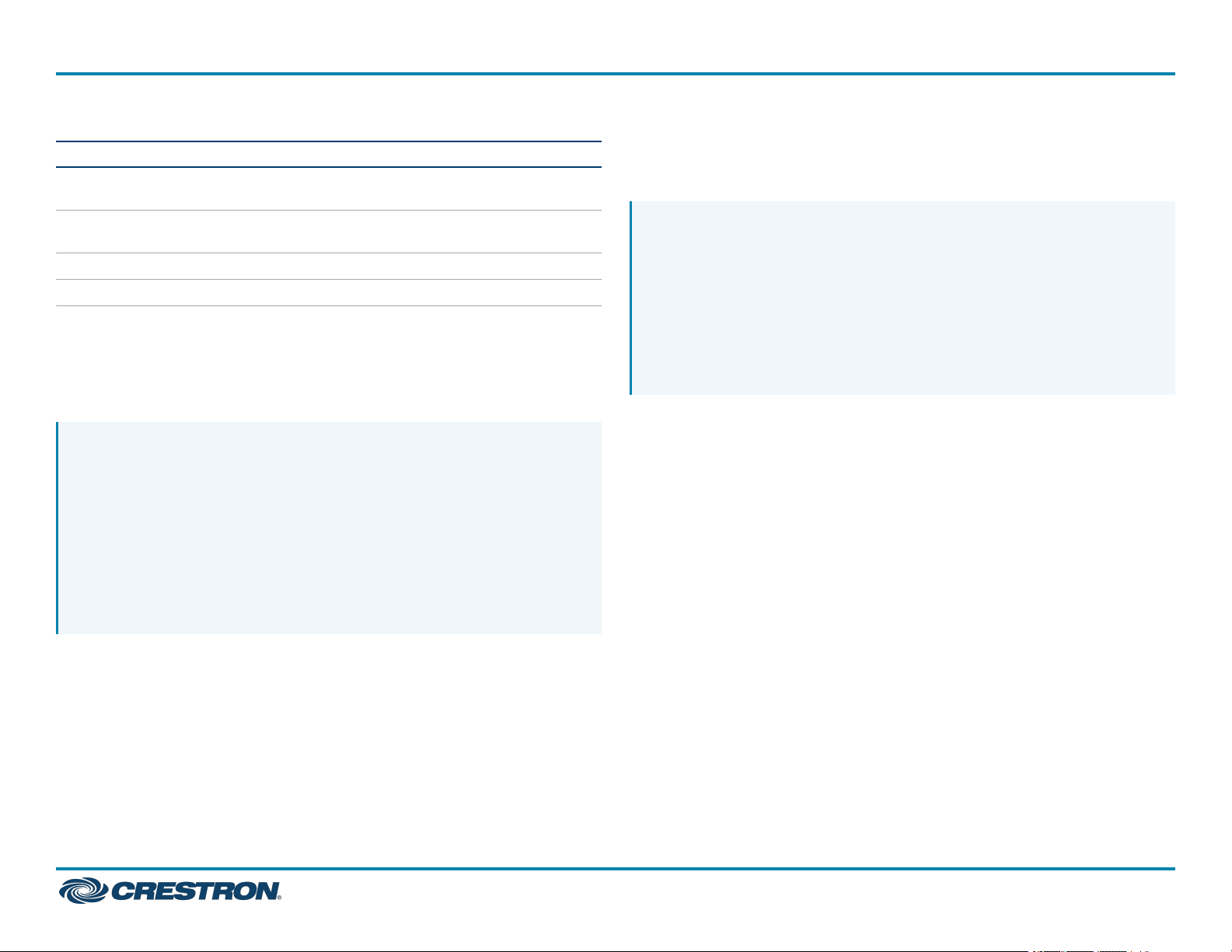
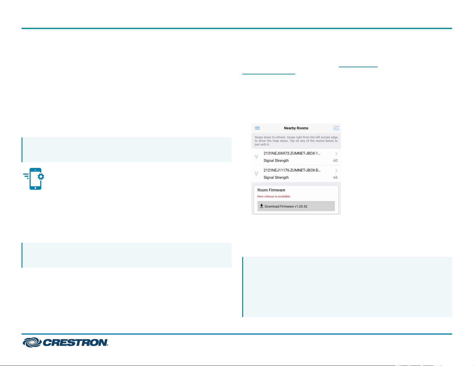
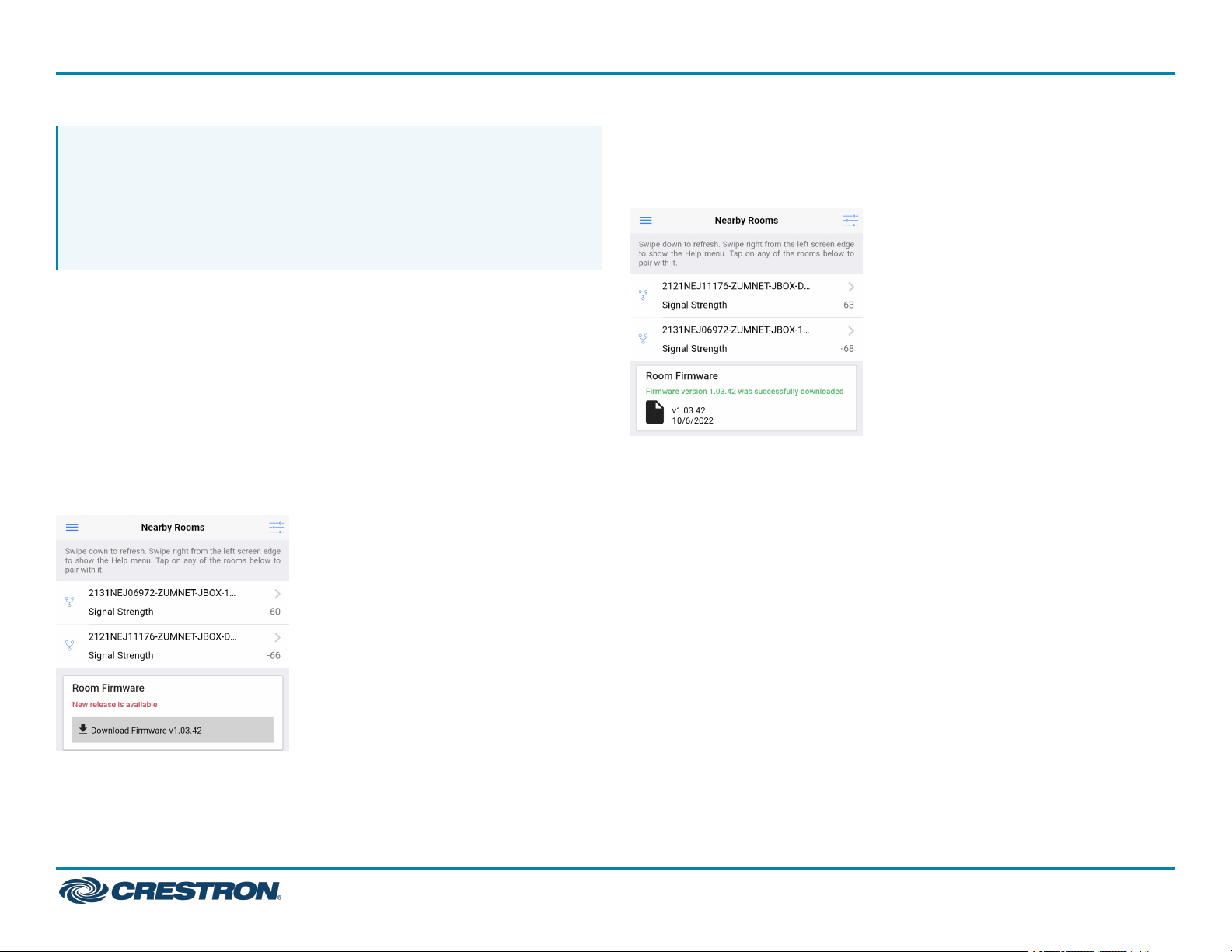
If new firmware is detected when connecting to the Zūm app, the Room
Firmware window appears on the Nearby Rooms screen.
Tap Download Firmware to load the firmware to the app. The Room
Firmware window message changes when the firmware is successfully
downloaded. The Zūm app is now ready to connect to the Zūm space
and start updating outdated devices.
11
Page 12
ZUMNET-JBOX Series
Zūm® Wired J-Box Load Controller with Net and Link Communication
QuickStart
Update Firmware for a Zūm Space
WARNING: Interrupting the firmware update can cause the update
to fail. To avoid interrupting the firmware update, follow these best
practices:
l
Place the mobile device in Do Not Disturb Mode.
l
Do not minimize or place the Zūm app in the background.
l
Do not lock the mobile device.
To update device firmware in a Zūm space.
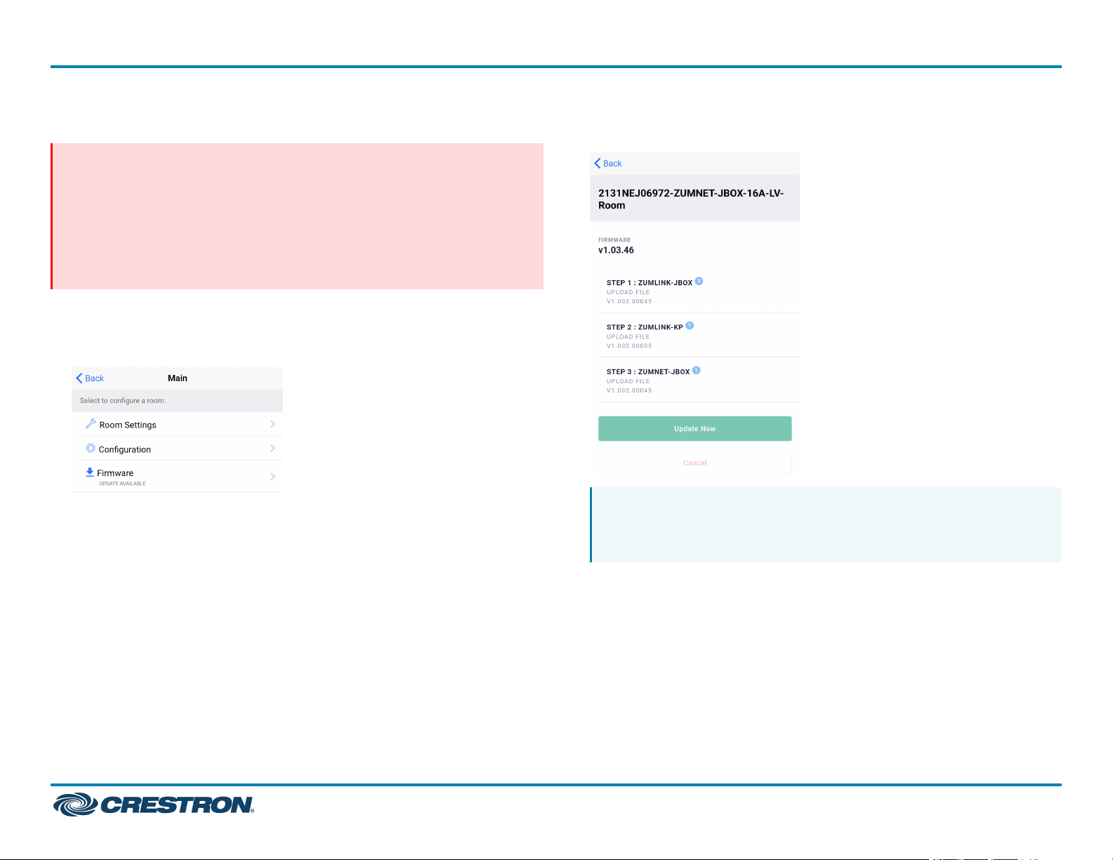
1. Choose the desired Zūm space to access the Main screen and tap
Firmware.
2. Tap Update Now to initiate the firmware update for STEP 1. Devices
are grouped based on the device type.
NOTE: The number next to the device type indicates the number
of devices of that type that need to be updated in that Zūm
space.
12
Page 13
ZUMNET-JBOX Series
Zūm® Wired J-Box Load Controller with Net and Link Communication
QuickStart
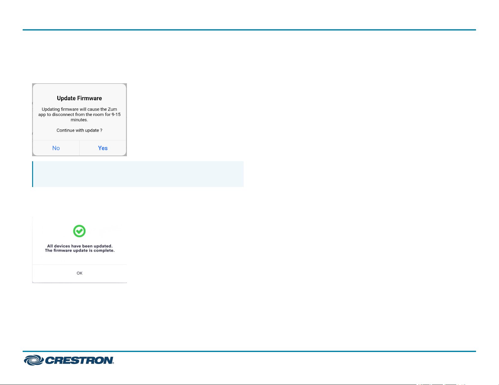
3. When the Update Firmware confirmation displays, select Yes to
continue or No to cancel and return to Firmware. The confirmation
also estimates the amount of time it will take to update the room
based on the number of devices.
NOTE: The Zūm space is inaccessible via Bluetooth until the
firmware update process is complete.
4. When all of the devices are updated in a Zūm space, a notification
displays stating the update is complete. Click OK, and repeat the
process for every Zūm space listed in Nearby Rooms.
5. If a device fails to update, a notification opens stating that some of
the devices were not updated. Click OK.
The notification closes and displays the Nearby Rooms screen. To
restart the firmware update, select the room and repeat the
procedure from step 1 until all of the devices have been successfully
updated.
13
Page 14
ZUMNET-JBOX Series
Zūm® Wired J-Box Load Controller with Net and Link Communication
Zūm App Main Screen
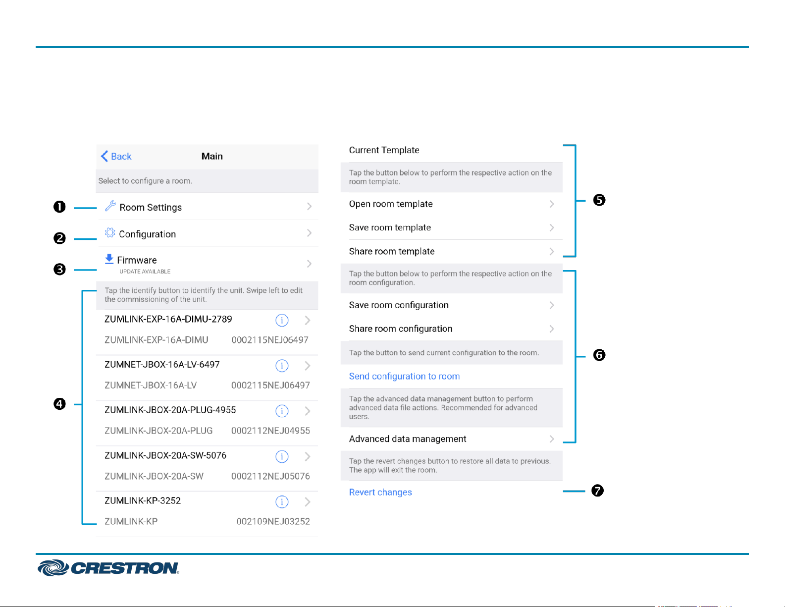
From the Nearby Rooms screen, tap the desired room to open the Main
screen. The following sections describe the actions available for each
area of the Main screen.
QuickStart
14
Page 15
ZUMNET-JBOX Series
Zūm® Wired J-Box Load Controller with Net and Link Communication
o
NOTE: The numbers below correspond with the numbers in the Main
screen diagram.
1. Room Settings: Edit the Room Name, PIN, Floor ID, Zone ID, and
Network information.
2. Configuration: Edit the room logic to view the current state of the
room.
l
Occupancy Sensors: View details for the connected sensor(s)
or edit the sensor name.
l
Photo Sensors: View details for the connected sensor(s) or edit
the sensor name.
l
Load Controllers: Identify and view details for the connected
load controller(s).
o
ZUMLINK-JBOX-16A-LV and ZUMNET-JBOX-16A-LV load
controllers:
n
View Current Scene, Daylighting status, and Output
Level.
n
Override: The state of the load when Override is recalled.
Click the toggle to turn the load on or off during
Override.
n
Assign the occupancy mode (Occupancy menu), vacancy
mode (Vacancy menu), vicinity mode (Vicinity menu), and
daylight harvesting (Photo menu) to specific load
controllers.
n
View Dimming Values
n
Edit the Dimming Curve Configuration or Dimmer
Scenes Configuration.
ZUMLINK-JBOX-20A-PLUG load controller:
n
Override: The state of the load when Override is recalled.
Click the toggle to turn the load on or off during
Override.
n
Assign the occupancy mode (Occupancy menu), vacancy
mode (Vacancy menu), vicinity mode (Vicinity menu), and
daylight harvesting (Photo menu) to specific load
controllers.
o
ZUMLINK-JBOX-20A-SW load controller:
n
Closed: Click the toggle to turn the load on or off.
n
Override: The state of the load when Override is recalled.
Click the toggle to turn the load on or off during
Override.
n
Assign the occupancy mode (Occupancy menu), vacancy
mode (Vacancy menu), vicinity mode (Vicinity menu), and
daylight harvesting (Photo menu) to specific load
controllers.
n
Scenes: Allow keypad access to the scene by selecting or
deselecting the checkbox. Determine the state of the
load when the scene is recalled by clicking the toggle on
or off.
QuickStart
15
Page 16
ZUMNET-JBOX Series
Zūm® Wired J-Box Load Controller with Net and Link Communication
QuickStart
o
ZUMLINK-EXP-16A-DIMU load controller:
n
View Current Scene, Daylighting status, and Output
Level.
n
Override: The state of the load when Override is recalled.
Click the toggle to turn the load on or off during
Override.
n
Assign the occupancy mode (Occupancy menu), vacancy
mode (Vacancy menu), vicinity mode (Vicinity menu), and
daylight harvesting (Photo menu) to specific load
controllers.
n
View Dimming Values.
n
Edit the Dimmer Scenes Configuration.
l
Scenes: View and edit room scenes: Scene 1 - Scene 16. When
editing the scene, tap the Identify icon to identify the load
controller. The load controller emits a sound and flashes the
Link LED. The connected loads also flash.
l
Keypads: Identify and view details for the connected keypad(s).
Edit the keypad name and assign the button layout.
o
Adjust the Double Tap Speed: Set the amount of time
between two button presses to qualify as a double tap.
o
Specify the Button Layout and click on a button to
configure button actions.
Button action options:
n
None
n
Off: Assigned load controllers turn off.
n
On: Assigned loads turn on.
n
Raise: Assigned load controllers raise.
n
Toggle: Switches load controllers between ON and
OFF states
n
Lower: Assigned load controllers lower.
n
Recall Scene 1 - Scene 16: Assigned load controllers
recall the behavior set for the specified scene.
n
Export to Hub: Name and send information to
ZUM-HUB4 for macro actions.
l
Load Shedding: Set the maximum levels for load shedding.
l
Load/Sensor Groups: Create groups within the room.
l
DALI Controllers: Address drivers, create DALI groups, assign
drivers, and identify drivers.
l
Current Scene: Displays the current room scene.
l
Occupancy Status: Displays occupied or vacant. If any area of
the room is occupied, then the status is Occupied. When all
areas of the room are vacant, the status is Vacant.
3. Firmware: To update firmware, refer to Update Firmware with the
Zūm App.
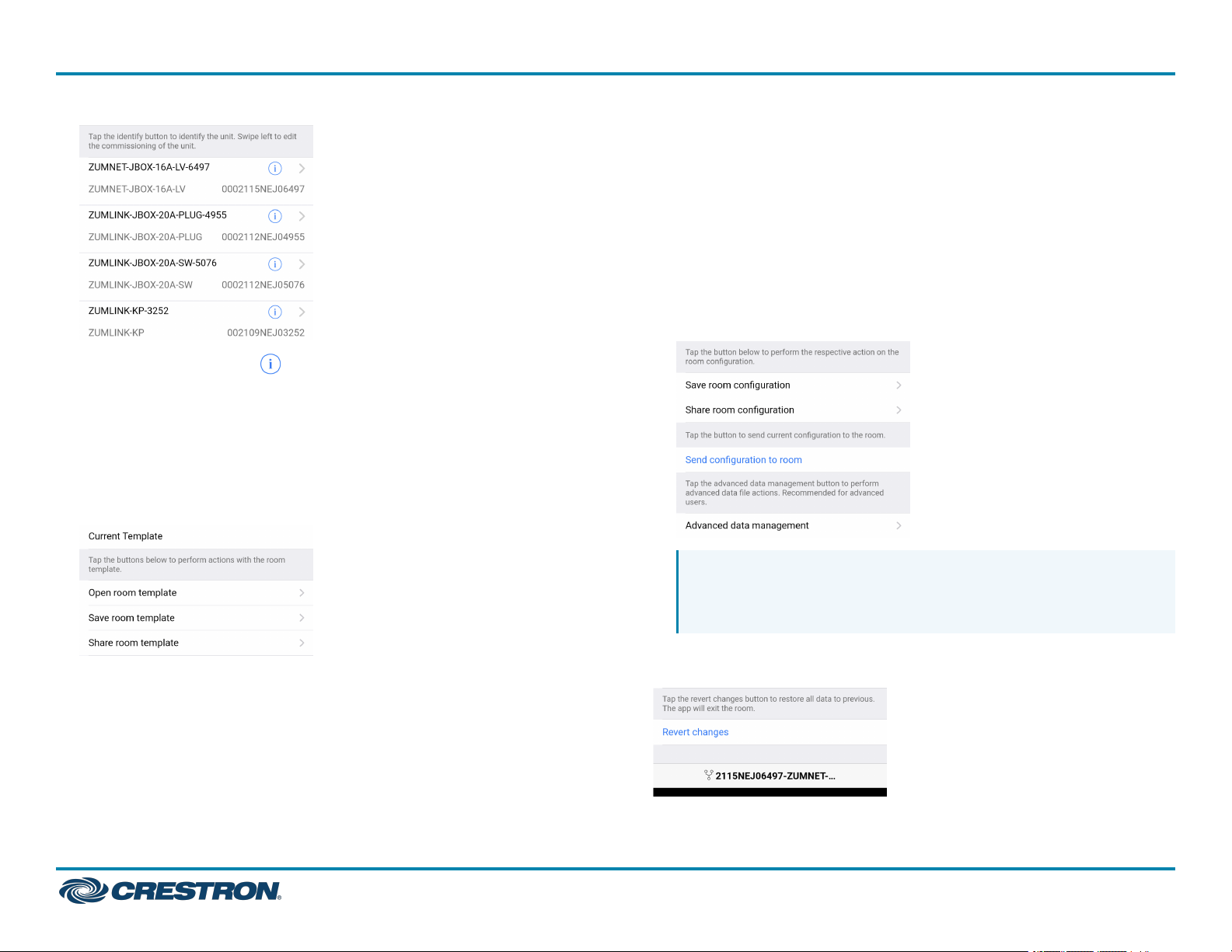
4. Discovered Room Devices: Identify a device and edit the
commissioning settings
16
Page 17
ZUMNET-JBOX Series
Zūm® Wired J-Box Load Controller with Net and Link Communication
6. Configuration Data:
l
Save room configuration: Save the room configuration data in the
space.
l
Share room configuration: Share the room configuration data in
the space.
l
Send configuration to room: Send room logic changes made in the
app to the room.
l
Advanced data management: Review the Map, Logic, and
Settings of the data currently loaded. Load, save or share new
Map, Logic, or Settings data.
l
Tap the Identify icon to identify a device. A load controller
emits a sound and the Link LED flashes. The connected loads also
flash. A keypad flashes its LED.
l
Tap the device to edit or review the device details: Edit Name.
Review the Model, Serial Number, Status, and edit the device
settings.
5. Current Template Settings: Choose Open room template, Save room
template, or Share room template.
QuickStart
NOTE: Changes made in the app are not sent to the room
until they are deployed using the Send configuration to room
button.
7. Revert changes: Restore all non-deployed changes made since
launching the app.
17
Page 18
ZUMNET-JBOX Series
Zūm® Wired J-Box Load Controller with Net and Link Communication
QuickStart
Calibrate Daylighting Settings for a Load Controller
The photocell component of a Zūm Net load controller, Zūm Link load
controller, or Zūm Link universal dimmer load controller detects the
amount of ambient light in the room. When a space is calibrated for
Daylighting and Scene 1 is called, the photocell will detect the ambient
light levels and dim the lights accordingly.
Calibrating Daylighting requires four main steps:
1. Assign the photocell component of a load controller to the load
controller.
2. Send the new configuration to the space.
3. Adjust the light level in the space.
4. Calibrate Daylighting.
To calibrate the daylight settings:
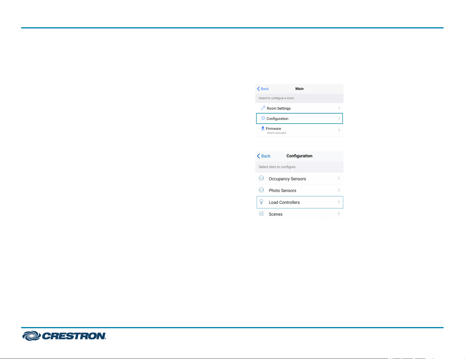
1. Assign the photocell component to the load controller that will
participate in Daylighting.
a. From the Main screen, click Configuration.
b. Click Load Controllers.
c. Click the desired load controller.
18
Page 19
ZUMNET-JBOX Series
Zūm® Wired J-Box Load Controller with Net and Link Communication
QuickStart
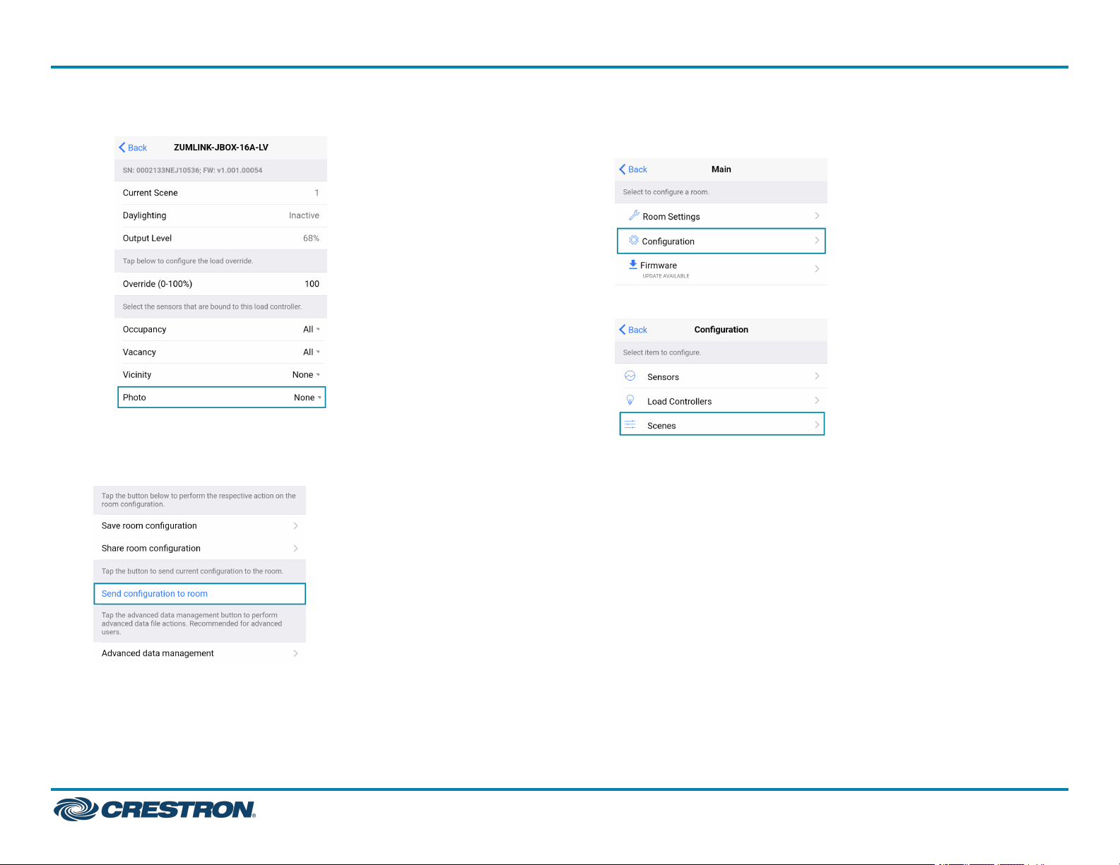
d. For Photo, select a photocell from the drop-down menu.
2. Send the configuration to the room.
a. Navigate back to the Main screen.
b. Click Send configuration to room.
3. Recall Scene 1 and adjust load levels.
a. From the Main screen, click Configuration.
b. Click Scenes.
A confirmation window opens stating that the app will disconnect
from the room. Click OKto continue or Cancel to close without
sending the configuration. The Retrieving Data Map screen
displays.
19
Page 20
ZUMNET-JBOX Series
Zūm® Wired J-Box Load Controller with Net and Link Communication
QuickStart
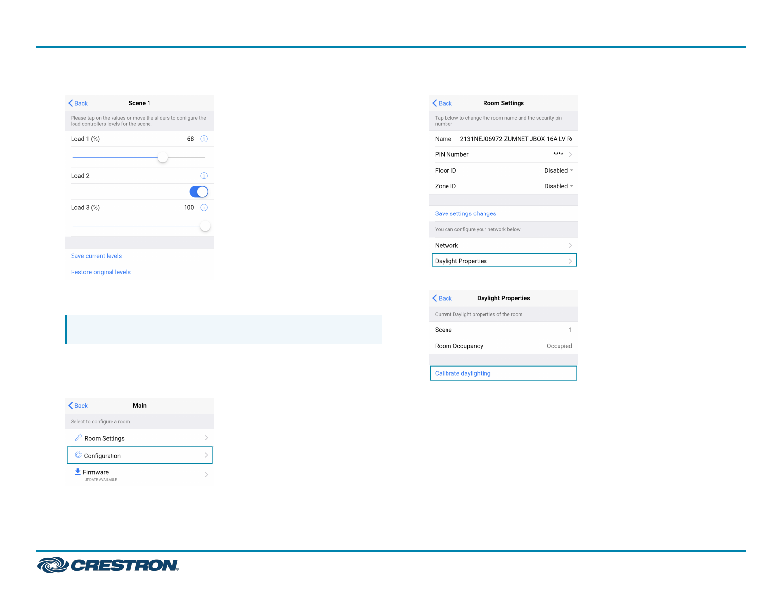
c. Select Scene 1. Daylighting is only available for Scene 1.
d. Adjust the loads in the space to the appropriate level based on the
amount of natural light.
NOTE: DO NOT click Save current levels.
4. Calibrate Daylighting.
a. Navigate back to the Main screen.
b. Click Room Settings.
c. Click Daylight Properties.
d. Click Calibrate Daylighting.
During Daylight calibration, the lights in the space will turn full on,
turn off, and then back on with the Daylighting settings.
Whenever Scene 1 is recalled, the Daylighting settings are
initiated.
20
Page 21
ZUMNET-JBOX Series
Zūm® Wired J-Box Load Controller with Net and Link Communication
QuickStart
DALICommissioning
Follow the required work flow for DALI commissioning of a DALI load
controller:
1. Confirm Operating mode (Operating Mode)
2. Address drivers (Addressing)
3. Create DALI groups (Add a Group)
NOTE: For DALI Groups mode only. Broadcast mode does not use
Groups. Refer to Operating Mode for more information.
4. Assign drivers (Assign Drivers to a Group)
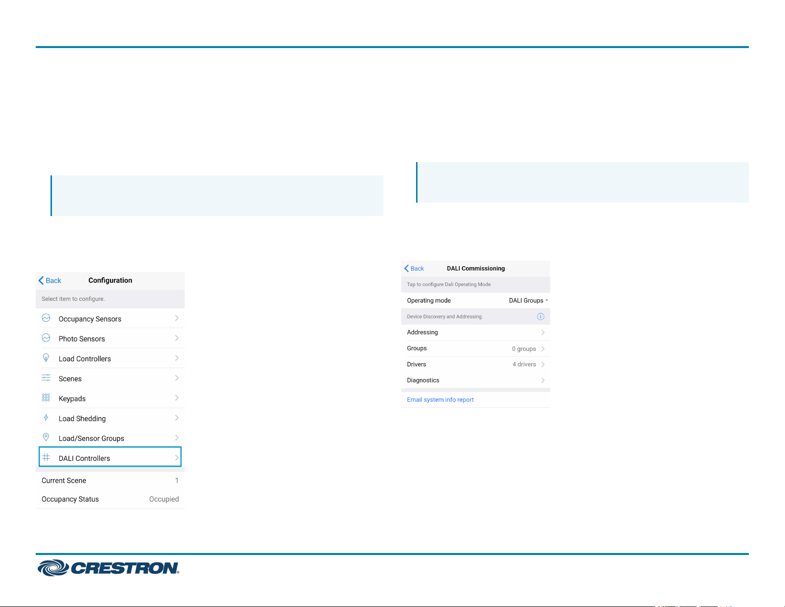
To begin the commissioning process, tap DALI Controllers in
Configuration.
Tap the desired DALI controller to open the DALI Commissioning screen.
The app may not respond until the system fully loads. The DALI
Commissioning screen offers the following options:
l
Addressing: Address all drivers and discover new drivers.
l
Groups: Assign drivers to DALI groups and review DALI group
assignments.
NOTE: For DALI Groups mode only. Broadcast mode does not use
Groups. Refer to Operating Mode for more information.
l
Drivers: Edit drivers and review their status.
l
Diagnostics: Start a diagnostics test and review results.
l
Email system info report: Send an system report to an email address.
Operating Mode
DALICommissioning operates in two modes: Broadcast or DALI Groups.
In Broadcast mode, every device connected to the DALI load controller
can be controlled in unison. In Groups mode, individual drivers can be
placed in groups for granular control over the devices.
To confirm the room's operating mode:
21
Page 22
ZUMNET-JBOX Series
Zūm® Wired J-Box Load Controller with Net and Link Communication
QuickStart
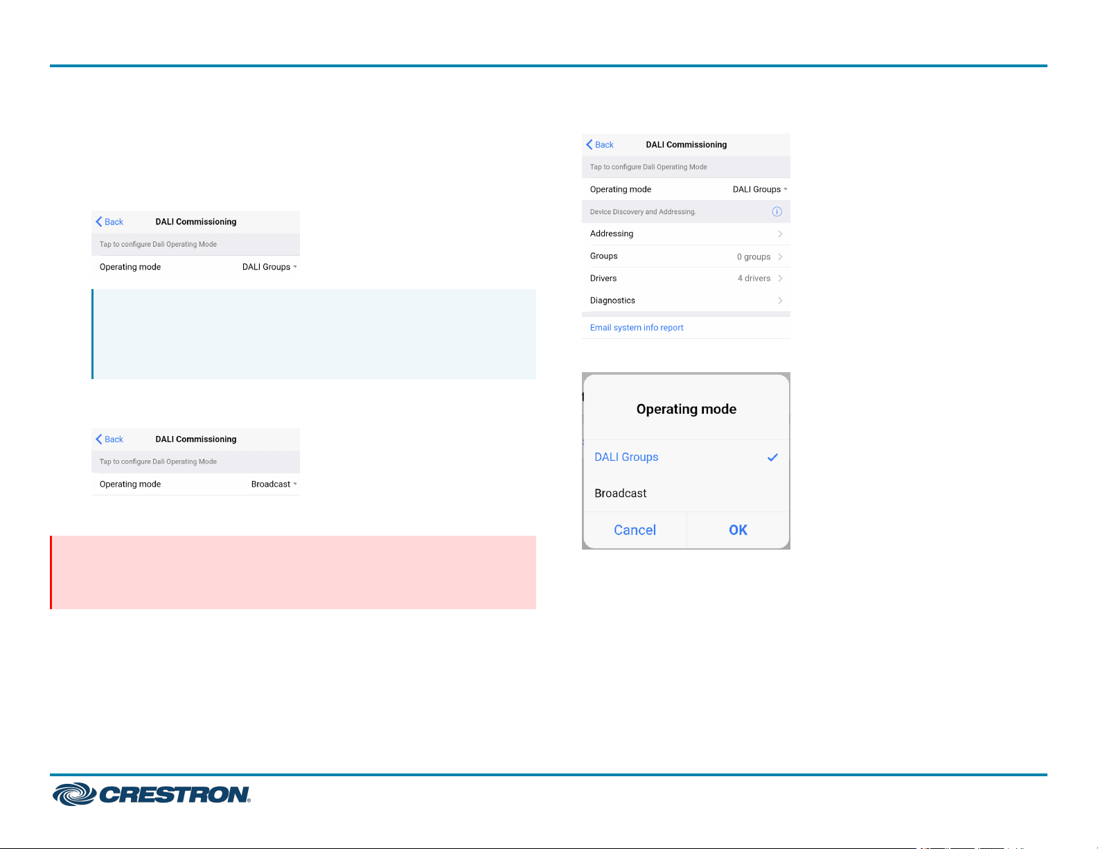
1. Navigate to Configuration>DALI Controllers>DALICommissioning
2. Review the DALI Commissioning screen.
l
If the Operating mode states DALI Groups or no operating mode
is identified, then the DALI load controller is operating in DALI
Groups mode.
NOTE:If Operating mode is not present on the
DALICommissioning screen, make sure to update to the
latest firmware. Refer to .Update Firmware with the Zūm
App.
l
If the Operating mode states Broadcast, then the DALI load
controller is operating in Broadcast mode.
To change the Operating mode:
1. Tap the current Operating mode to open the Operating mode menu.
2. Select either DALI Groups or Broadcast.
NOTE: Changing the Operating mode affects keypad programming
assignments. Review the assignments after implementing the
change.
3. Tap OK to continue and a warning dialog opens.
22
Page 23
ZUMNET-JBOX Series
Zūm® Wired J-Box Load Controller with Net and Link Communication
QuickStart
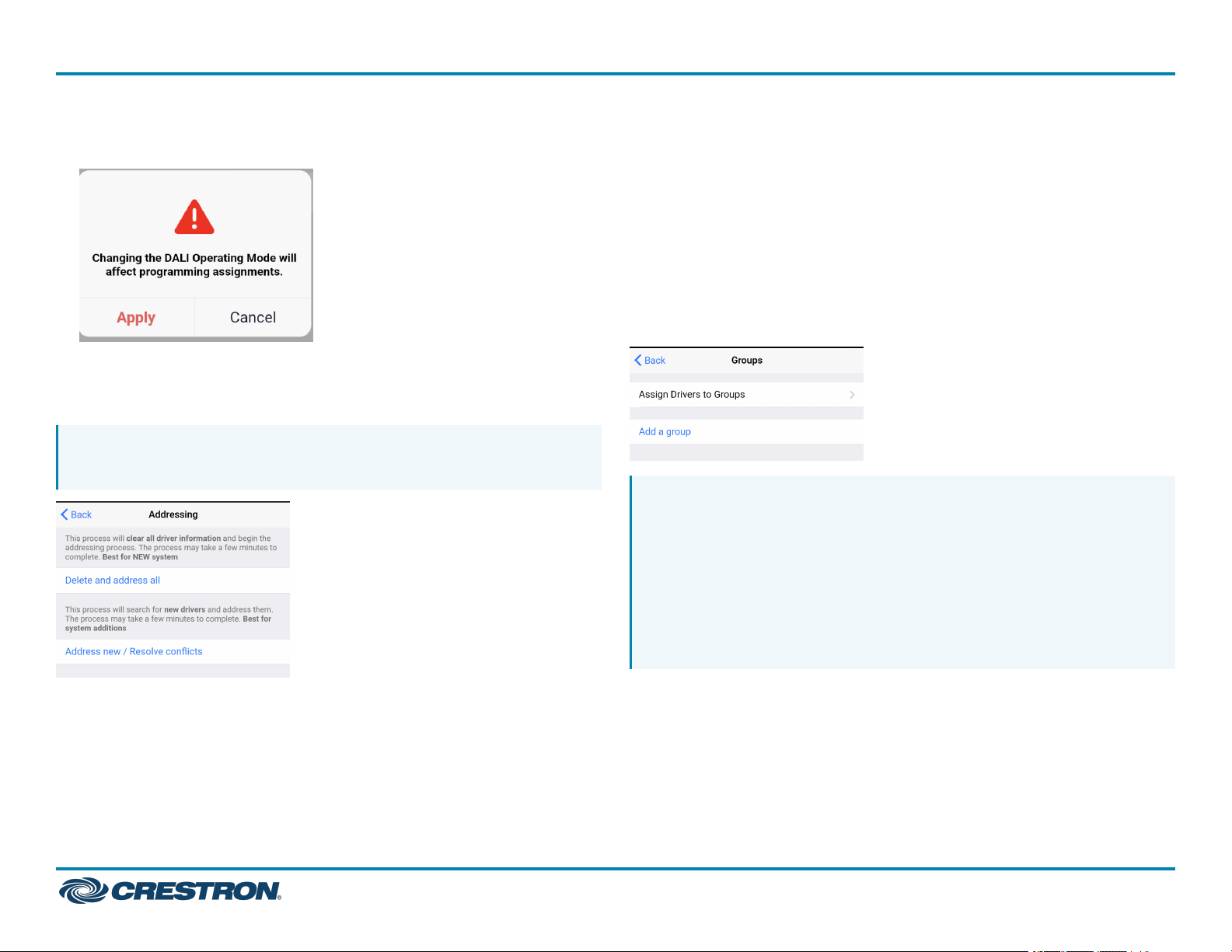
4. Tap Apply to change the Operating mode or Cancel to close without
making a change.
Addressing
Use Addressing to discover new drivers for a new or established system.
NOTE: Addressing is required in DALI Groups Operating mode but is
optional in Broadcast Operating mode.
Established Systems
Tap Address New / Resolve Conflicts to discover new drivers and add
them to a system. Each driver must have a unique address. If there are
duplicate addresses, resolve the conflict. When the confirmation window
opens, tap OK to continue or Cancel to close without addressing the
system.
Groups
Use Groups to assign drivers to a DALI group and review DALI group
assignments.
NOTES:
l
For DALI Groups mode only. Broadcast mode does not use
Groups. Refer to Operating Mode for more information.
l
DALI groups also appear as load controllers in
Configuration>Load Controllers. The DALI groups are inactive
until a DALI group has been created in Groups. DALI groups are
not the same as load controller groups or occupancy sensor
groups.
New Systems
Tap Delete and Address All to delete any driver information and begin
the addressing process. When the confirmation window opens, tap OK
to continue or Cancel to exit without readdressing the system.
23
Page 24
ZUMNET-JBOX Series
Zūm® Wired J-Box Load Controller with Net and Link Communication
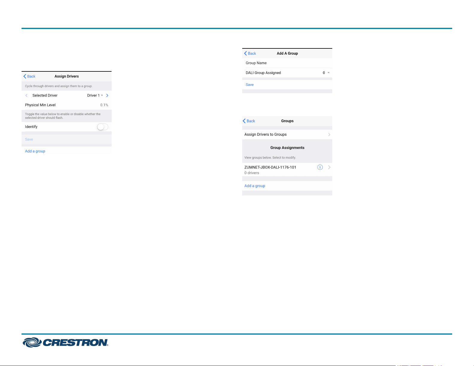
Assign Drivers to a Group
Tap Assign Drivers to assign a driver to a DALI group.
The previous screen appears with the new DALI group listed under
Group Assignments.
l
Selected Driver: Choose a driver to assign. Tap < or > to cycle through
the drivers. The Physical Min Level is stated.
The Physical Min Level is the actual level (%) the driver is capable of
lowering to. Only Drivers with the same Physical Min Level should be
added to the same DALI group.
l
Identify: Tap the toggle to enable or disable whether the selected
driver should flash.
l
DALI groups: Tap the check box next to the desired DALI group. Tap
Save to save the changes or tap Back to return to the previous screen
without saving.
l
Add a group: Opens the same screen as Add a Group.
QuickStart
Add a Group
Tap Save to save the DALI group.
24
Page 25
ZUMNET-JBOX Series
Zūm® Wired J-Box Load Controller with Net and Link Communication
l
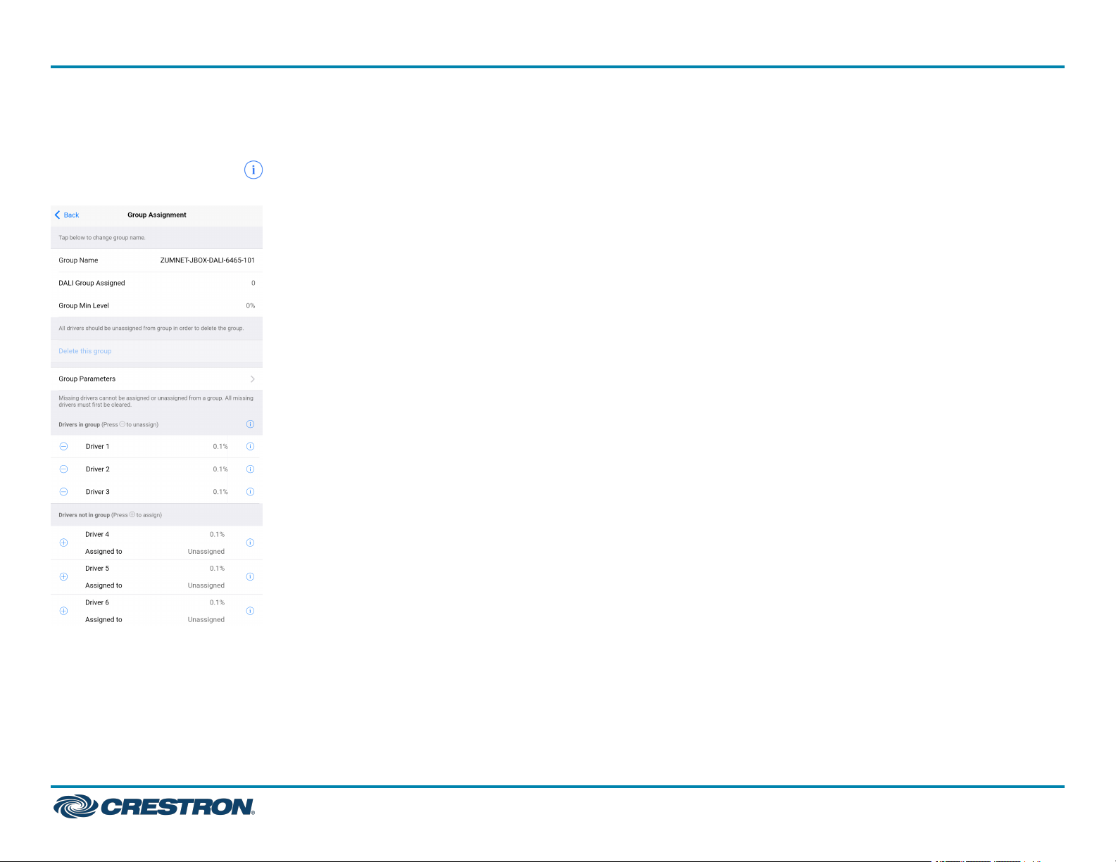
Group Assignments
Created DALI groups are listed under Group Assignments. To flash
drivers, tap the Identify icon next to Drivers in group to flash all
drivers in the group or next to a driver to identify a single driver.
Group Min Level: Displays the value set in View Dimming Properties >
Min Level (0-45%).
l
Delete this Group: Tap to delete the DALI group.
Delete this Group is only enabled after all drivers are removed from
the group.
QuickStart
l
Group Name: Tap to edit the DALI group name.
After editing the Group Name, save the new name by tapping the go
or enter button on your phone’s keyboard or tapping outside of the
Group Name field.
l
DALI Group Assigned: Displays the group number of the DALI group.
25
Page 26
ZUMNET-JBOX Series
Zūm® Wired J-Box Load Controller with Net and Link Communication
QuickStart
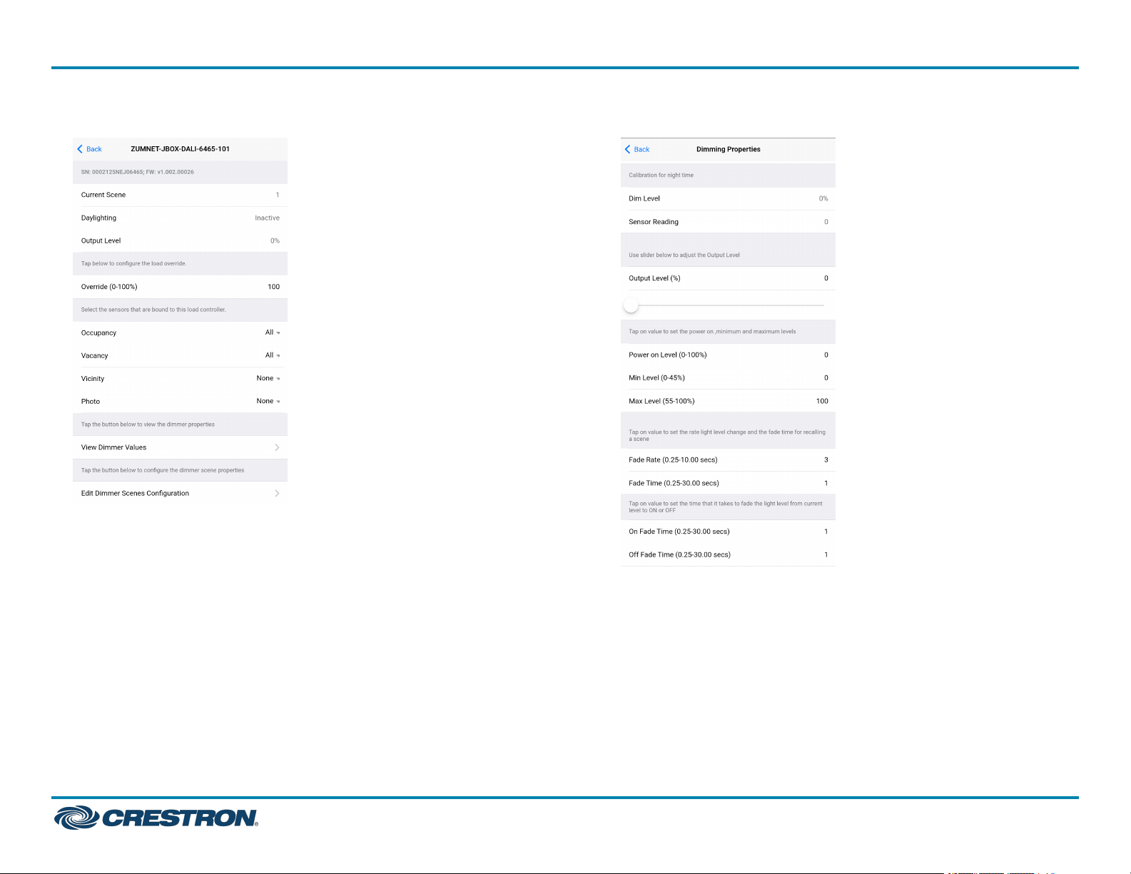
l
Group Parameters: Tap to access the Group Parameters.
o
Current scene
o
Daylighting
o
Output Level
o
Override
o
Occupancy
o
Vacancy
o
Vicinity
o
Photo
o
View Dimmer Values
n
Dim Level: Review the dimming level set for day and night
calibration.
n
Sensor Reading: Review the sensor reading intensity for day
and night calibration.
n
Output Level: Use the slider to adjust the Output level.
n
Power on Level (0-100%): Set the light level when powering
On.
26
Page 27
ZUMNET-JBOX Series
Zūm® Wired J-Box Load Controller with Net and Link Communication
n
Min Level (0-45%): Set the minimum light level threshold a
driver cannot pass.
n
Max Level (55-100%): Set the maximum light level threshold a
driver cannot pass.
n
Fade Rate (0.25-10.00 secs): Set the amount of time it takes
to raise the light level from 0% to 100% or dim the level from
100% to 0% when pressing the raise or lower buttons on a
keypad.
n
Fade Time (0.25-30.00 secs): Set the amount of time to fade
from the current light level to a recalled scene or discrete level.
n
On Fade Time (0.25-30.00 secs): Set the amount of time to
fade from the current light level to the On scene.
n
Off Fade Time (0.25-30.00 secs): Set the amount of time to
fade from the current light level to the Off scene.
o
Edit Dimmer Scene Configurations. Tap on the value or move the
sliders to configure levels for each scene. To exclude scenes from
participating in the group, uncheck the box next to the scene.
l
Drivers in group and Drivers not in group: Tap + to add a driver to the
DALI group or tap - to remove a driver from the DALI group.
l
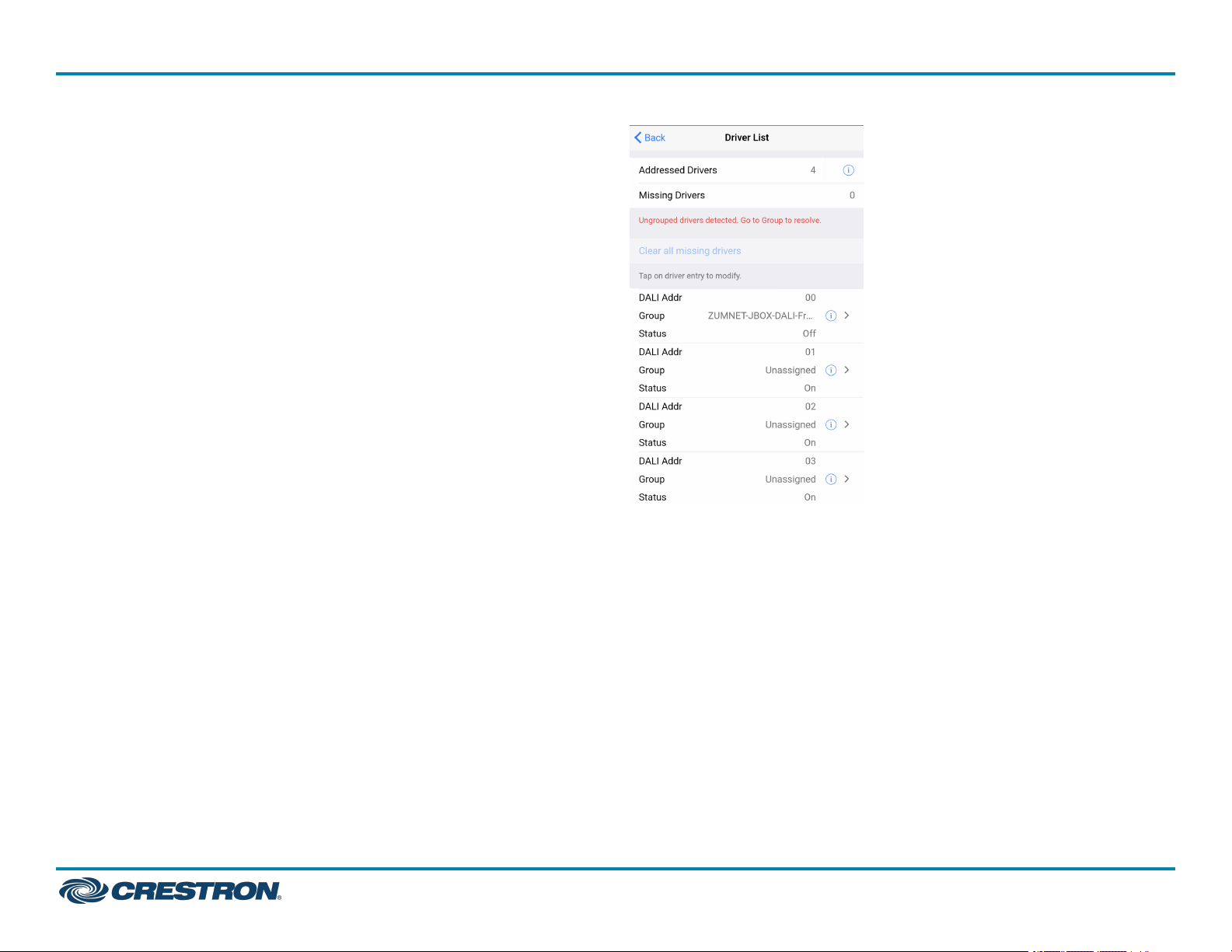
Addressed Drivers: States the number of drivers addressed.
Drivers
Use the Drivers screen to review the Drivers List.
l
Missing Drivers: States the number of drivers missing. Missing drivers
are drivers that were previously addressed but currently can not be
found.
The Status is displayed as Missing in red to indicate which driver
needs to be checked.
l
If drivers have been addressed but not assigned to a DALI group, the
message "Unassigned drivers detected. Go to Groups to resolve."
appears. Drivers must be assigned to a DALI group before they can
be controlled.
l
If missing drivers are detected, Clear all missing drivers is active. Tap
Clear all missing drivers to delete the addressed information. Return
to Addressing and tap Address New / Resolve Conflicts.
QuickStart
27
Page 28
ZUMNET-JBOX Series
Zūm® Wired J-Box Load Controller with Net and Link Communication
l
Drivers listed: Each listed driver states the DALI Address number
(00-63), the Group name or Unassigned, and the Status (On, Off, or
Missing).
Tap the Identify icon . The drivers flash, identifying the driver.
Tap on the driver to access the Driver Setting.
o
Review Driver details such as DALIAddress, Long Address,
Physical Min Level, Driver Type, and Status.
o
Change the DALI Address. Chose a number 00-63 and tap Save to
save the new address. Only available addresses can be selected.
Addresses already assigned to another driver are grayed out and
cannot be selected.
o
Review the name of the group the driver is assigned to and the
Min Level Set.
o
Tap Grouping to access Assign Drivers. The same screen as Assign
Drivers to a Group opens.
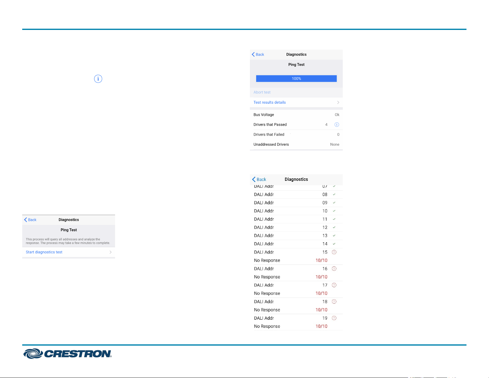
Diagnostics
Tap Test result details to view the driver address and how many times
out of 10 the driver did not respond to a ping.
QuickStart
Use the Diagnostics screen to test the DALI loop for the selected DALI
controller.
Tap Start diagnostics test to begin a Ping Test. The test pings each
driver ten times to trigger a response and report the following data:
l
Status of bus voltage
l
Number of drivers that passed
l
Number of drivers that failed
l
Presence of unassigned drivers
28
Page 29
ZUMNET-JBOX Series
Zūm® Wired J-Box Load Controller with Net and Link Communication
QuickStart
Additional Information
Original Instructions
The U.S. English version of this document is the original instructions.
All other languages are a translation of the original instructions.
Regulatory Model: M201933001, M201933003
This product may be purchased from select authorized Crestron dealers and distributors.
To find a dealer or distributor, please contact the Crestron sales representative for your
area. A list of sales representatives is available online at www.crestron.com/How-To-
Buy/Find-a-Representative or by calling 855-263-8754.
Crestron product development software is licensed to Crestron dealers and Crestron
Service Providers (CSPs) under a limited nonexclusive, nontransferable Software
Development Tools License Agreement. Crestron product operating system software is
licensed to Crestron dealers, CSPs, and end-users under a separate End-User License
Agreement. Both of these Agreements can be found on the Crestron website at
www.crestron.com/legal/software_license_agreement.
The product warranty can be found at www.crestron.com/warranty.
The specific patents that cover Crestron products are listed online at
www.crestron.com/legal/patents.
Certain Crestron products contain open source software. For specific information, please
visit www.crestron.com/opensource.
Crestron, the Crestron logo, Crestron Toolbox, and Zūm are either trademarks or
registered trademarks of Crestron Electronics, Inc. in the United States and/or other
countries. App Store and Apple are either trademarks or registered trademarks of Apple,
Inc. in the United States and/or other countries. Bluetooth is either a trademark or
registered trademark of Bluetooth SIG, Inc. in the United States and/or other countries.
IOS is either a trademark or registered trademark of Cisco Systems, Inc. in the United
States and/or other countries. Google Play is either a trademark or registered trademark
of Google Inc. in the United States and/or other countries. Wi-Fi is either a trademark or
registered trademark of Wi-Fi Alliance in the United States and/or other countries.DALI is
either a trademark or registered trademark of IEEE Industry Standards and Technology
Organization, Inc. in the United States and/or other countries. Other trademarks,
registered trademarks, and trade names may be used in this document to refer to either
the entities claiming the marks and names or their products. Crestron disclaims any
proprietary interest in the marks and names of others. Crestron is not responsible for
errors in typography or photography.
©2023 Crestron Electronics, Inc.
06/29/23
Doc ID 8856J
29
 Loading...